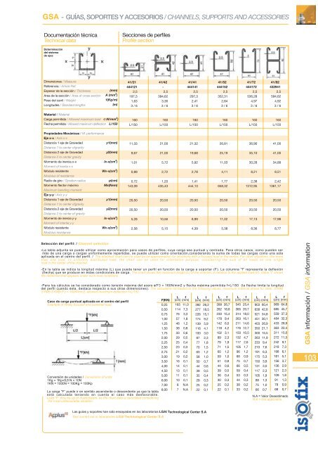
GSA - GUÍAS, SOPORTES Y ACCESORIOS / CHANNELS, SUPPORTS AND ACCESSORIESDocumentación técnicaTechnical dataSecciones de perfilesProfile sectionDeterminacióndel sistemade ejesDimensiones / MeasureReferencia / Article Ref.Espesor de la sección / ThicknessArea de la sección / Area of cross sectionPeso del carril / WeightLongitudes / Standard lengths30/133330251,272,80,576235/133330271,278,20,618250/133330281,296,20,76240/203330251,5115,30,9682Material / MaterialCarga permitida / Allowed maximum loadFlecha permitida / Allowed maximum deflection160L/150160L/150160L/150160L/150Propiedades Mecánicas / M. performanceEje x-x / Axis x-xDistancia 1 eje de GravedadDistance 1 to center ofgravityDistancia 2 eje de GravedadDistance 2 to center gravityMomento de inercia x-xMoment of inertia x-xMódulo resistenteModulus of resistanceRadio de giro / Gyration radiusMomento flector máximoMaximum bending momentEje y-y / Axis y-yDistancia 1 eje de GravedadDistance 1 to center ofgravityDistancia 2 eje de GravedadDistance 2 to center of gravityMomento de inercia y-yMoment of intertia y-yMódulo resistenteModulus resistance6,506,500,190,290,5146,4415,0015,001,030,697,006,000,210,290,5147,0117,5017,501,520,878,014,990,250,310,5149,6425,0025,003,681,4711,328,680,650,580,7592,0520,0020,003,191,60GSA información / GSA information102Selección del perfil: / Channel selection-La tabla adjunta se puede utilizar como aproximación para casos de perfiles, cuya carga sea puntual y centrada. Para otros casos, como pueden sermás de una carga o cargas uniformemente repartidas, se puede utilizar como orientación,considerando la suma de todas las cargas como una solaaplicada en el centro del perfil. / The attached chart can be used as an approximation for situations with a focused load in the center. For other situations, like morethan one load, or uniformly distributed load, the chart can be used for orientation purpose, considering the sum of all loads as one singleload in the center of the channel.-En la tabla se indica la longitud máxima (L) que puede tener un perfil en función de la carga a soportar (F). La columna "f" representa la deflexión(flecha) que se produce en estas condiciones de carga. / The chart shows the maximum length (L) of the channel, in relation to the applied load (F). Value “f” showsthe deflection that appears under such load conditions.-Para los cálculos se ha considerado como tensión máxima del acero s'F3 = 160N/mm2 y f echa máxima permitida f=L/150 (la flecha limita la longituddel perfil cuando ésta, destaca respecto a sus otras dimensiones). / The calculation ist based on the following values: maximum material stress for steel, SYMBSYMB SYMB•'F3 = 160N/mm2, allowed maximum deflection f=L/150.Caso de carga puntual aplicada en el centro del perfilExample of timely focused and centered loadConversión de unidades / Conversion of units1Kg = 1Kp=9,8 N = 10N1KN = 1000N = 100Kg = 100KpLa carga “F” puede ir en sentido ascendente o descendente ya que la tablaestá calculada teniendo en cuenta el caso más desfavorable.Load “F” may be up or downstream, as the chart data is caluclated consideringthe most unfavourable situation.F(KN)0,100,150,200,250,300,400,500,751,001,251,501,752,002,252,502,753,003,504,00L(cm)11392807162463725191512119877655f(mm)7,56,15,34,73,72,11,30,60,30,20,10,10,10,10,1N.AN.AN.AN.AL(cm)11896837463473825191513119887655f(mm)7,96,45,55,03,62,01,30,60,30,20,10,10,10,10,1N.AN.AN.AN.AL(cm)1291069179665040262016131110987765f(mm)8,67,06,15,03,52,01,30,60,30,20,10,10,10,10,1N.AN.AN.AN.AL(cm)209171148132121927449372925211816151312119f(mm)40,933,328,925,823,520,418,214,98,65,53,82,82,11,71,41,11,00,70,5N.A = Valor DesestimadoN.A = Not applicableLas guías y soportes han sido ensayadas en los laboratorios LGAI Technological Center S.ATest carried out in laboratories LGAI Technological Center S.A
GSA - GUÍAS, SOPORTES Y ACCESORIOS / CHANNELS, SUPPORTS AND ACCESSORIESDocumentación técnicaTechnical dataSecciones de perfilesProfile sectionDeterminacióndel sistemade ejesDimensiones / MeasureReferencia / Article Ref.Espesor de la sección / ThicknessArea de la sección / Area of cross sectionPeso del carril / WeightLongitudes / Standard lengths41/214441212,5197,31,633 / 641/42-2,5394,623,363 / 641/414441412,5297,32,413 / 641/524441522,5352,312,843 / 641/724441722,5536,284,973 / 641/824329412,5594,624,923 / 6Material / MaterialCarga permitida / Allowed maximum loadFlecha permitida / Allowed maximum deflection160L/150160L/150160L/150160L/150160L/150160L/150Propiedades Mecánicas / M. performanceEje x-x / Axis x-xDistancia 1 eje de GravedadDistance 1 to center ofgravityDistancia 2 eje de GravedadDistance 2 to center gravityMomento de inercia x-xMoment of inertia x-xMódulo resistenteModulus of resistanceRadio de giro / Gyration radiusMomento flector máximoMaximum bending momentEje y-y / Axis y-yDistancia 1 eje de GravedadDistance 1 to center ofgravityDistancia 2 eje de GravedadDistance 2 to center of gravityMomento de inercia y-yMoment of intertia y-yMódulo resistenteModulus resistance11,339,671,010,890,72143,0920,5020,505,282,5821,0021,005,722,721,20435,4320,5020,5010,565,1521,3219,685,922,781,41444,1320,5020,508,994,3926,8125,1911,034,111,77658,3220,5020,5011,025,3836,9035,1030,288,212,381312,9520,5020,5017,138,3641,0041,0034,888,512,421361,1720,5020,5017,988,77Selección del perfil: / Channel selection-La tabla adjunta se puede utilizar como aproximación para casos de perfiles, cuya carga sea puntual y centrada. Para otros casos, como pueden sermás de una carga o cargas uniformemente repartidas, se puede utilizar como orientación,considerando la suma de todas las cargas como una solaaplicada en el centro del perfil. / The attached chart can be used as an approximation for situations with a focused load in the center. For other situations, like morethan one load, or uniformly distributed load, the chart can be used for orientation purpose, considering the sum of all loads as one singleload in the center of the channel.-En la tabla se indica la longitud máxima (L) que puede tener un perfil en función de la carga a soportar (F). La columna "f" representa la deflexión(flecha) que se produce en estas condiciones de carga. The chart shows the maximum length (L) of the channel, in relation to the applied load (F). Value “f” showsthe deflection that appears under such load conditions.-Para los cálculos se ha considerado como tensión máxima del acero s'F3 = 160N/mm2 y flecha máxima permitida f=L/150 (la flecha limita la longituddel perfil cuando ésta, destaca respecto a sus otras dimensiones). The calculation ist based on the following values: maximum material stress for steel, SYMBSYMB SYMB•'F3 = 160N/mm2, allowed maximum deflection f=L/150.Caso de carga puntual aplicada en el centro del perfilExample of timely focused and centered loadConversión de unidades / Conversion of units1Kg = 1Kp=9,8 N = 10N1KN = 1000N = 100Kg = 100KpLa carga “F” puede ir en sentido ascendente o descendente ya que la tablaestá calculada teniendo en cuenta el caso más desfavorable.Load “F” may be up or downstream, as the chart data is caluclated consideringthe most unfavourable situation.F(KN)0,250,500,751,001,251,501,752,002,252,502,753,003,504,004,505,006,007,008,00L f(cm) (mm)165 11,0114 7,376 3,357 1,846 1,238 0,833 0,629 0,525 0,423 0,321 0,219 0,216 0,114 0,113 0,111 0,110 0,18 N.A7 N.AL f(cm) (mm)392 26,2277 18,5226 15,1174 9,2139 5,9116 4,1100 3,087 2,377 1,870 1,563 1,258 1,050 0,744 0,639 0,535 0,429 0,325 0,222 0,1L f(cm) (mm)399 26,7282 18,8230 15,4178 9,4142 6,0118 4,2102 3,189 2,379 1,971 1,565 1,259 1,051 0,844 0,639 0,536 0,430 0,325 0,222 0,1L f(cm) (mm)545 25,4385 20,7314 18,0263 16,1211 14,6176 12,7150 10,5132 4,7117 2,6105 1,796 1,288 0,975 0,766 0,559 0,453 0,344 0,338 0,233 0,2L f(cm) (mm)903 60,4638 42,6521 34,8451 30,1403 26,9350 21,1300 15,5263 11,9233 9,4210 7,6191 6,3175 5,3150 3,9131 3,0117 2,3105 1,988 1,375 1,066 0,7L f(cm) (mm)969 64,8685 45,7559 37,3484 32,3433 28,9363 20,4311 15,0272 11,5242 9,1218 7,3198 6,1181 5,1156 3,7136 2,9121 2,3109 1,891 1,378 0,968 0,7N.A = Valor DesestimadoN.A = Not applicableGSA información / GSA information103Las guías y soportes han sido ensayadas en los laboratorios LGAI Technological Center S.ATest carried out in laboratories LGAI Technological Center S.A
- Page 2 and 3:
Isostrut DobleDouble IsostrutGuía
- Page 4 and 5:
INDICE DE PRODUCTOS / PRODUCT INDEX
- Page 6 and 7:
INFO - INFORMACIÓN TÉCNICA / TECH
- Page 8 and 9:
INFO - INFORMACIÓN TÉCNICA / TECH
- Page 10 and 11:
INFO - INFORMACIÓN TÉCNICA / TECH
- Page 12 and 13:
114 pág. 12 126 pág. 12 149 pág.
- Page 14 and 15:
AMP - ABRAZADERAS METÁLICAS PESADA
- Page 16 and 17:
AMP - ABRAZADERAS METÁLICAS PESADA
- Page 18 and 19:
AMP - ABRAZADERAS METÁLICAS PESADA
- Page 20 and 21:
AMP - ABRAZADERAS METÁLICAS PESADA
- Page 22 and 23:
AMP - ABRAZADERAS METÁLICAS PESADA
- Page 24 and 25:
AMP - ABRAZADERAS METÁLICAS PESADA
- Page 26 and 27:
AMP - ABRAZADERAS METÁLICAS PESADA
- Page 28 and 29:
1AMP - ABRAZADERAS METÁLICAS PESAD
- Page 30 and 31:
1AMP - ABRAZADERAS METÁLICAS PESAD
- Page 32 and 33:
153 pág. 32 137 pág. 33 130 pág.
- Page 34 and 35:
153Abrazadera Isofónica UniclipIno
- Page 36 and 37:
130Abrazadera ReforzadaInox M8/10St
- Page 38 and 39:
176Ventajas / AdvantagesAbrazadera
- Page 40 and 41:
€ud/pc1,3601,5301,7902,3003,570
- Page 42 and 43:
600Escuadra de Montaje InoxStainles
- Page 44 and 45:
€ud/pc0,3100,580Medida / Measure
- Page 46 and 47:
€ud/pc1,3602,4602,4603,570Taco/Pl
- Page 48 and 49:
140 pág. 48 610 pág. 48 141 pág.
- Page 50 and 51:
AML - ABRAZADERAS METÁLICAS LIGERA
- Page 52 and 53:
AML - ABRAZADERAS METÁLICAS LIGERA
- Page 54 and 55: AML - ABRAZADERAS METÁLICAS LIGERA
- Page 56 and 57: AML - ABRAZADERAS METÁLICAS LIGERA
- Page 58 and 59: AML - ABRAZADERAS METÁLICAS LIGERA
- Page 60 and 61: AML - ABRAZADERAS METÁLICAS LIGERA
- Page 62 and 63: AML - ABRAZADERAS METÁLICAS LIGERA
- Page 64 and 65: AML - ABRAZADERAS METÁLICAS LIGERA
- Page 66 and 67: 225 pág. 66 226 pág. 66 212 pág.
- Page 68 and 69: APL - ABRAZADERAS DE PLÁSTICO / PL
- Page 70 and 71: APL - ABRAZADERAS DE PLÁSTICO / PL
- Page 72 and 73: APL - ABRAZADERAS DE PLÁSTICO / PL
- Page 74 and 75: APL - ABRAZADERAS DE PLÁSTICO / PL
- Page 76 and 77: APL - ABRAZADERAS DE PLÁSTICO / PL
- Page 78 and 79: APL - ABRAZADERAS DE PLÁSTICO / PL
- Page 80: APL - ABRAZADERAS DE PLÁSTICO / PL
- Page 83 and 84: GUÍAS, SOPORTES Y ACCESORIOSCHANNE
- Page 85 and 86: GSA - GUÍAS, SOPORTES Y ACCESORIOS
- Page 87 and 88: GSA - GUÍAS, SOPORTES Y ACCESORIOS
- Page 89 and 90: GSA - GUÍAS, SOPORTES Y ACCESORIOS
- Page 91 and 92: GSA - GUÍAS, SOPORTES Y ACCESORIOS
- Page 93 and 94: GSA - GUÍAS, SOPORTES Y ACCESORIOS
- Page 95 and 96: GSA - GUÍAS, SOPORTES Y ACCESORIOS
- Page 97 and 98: GSA - GUÍAS, SOPORTES Y ACCESORIOS
- Page 99 and 100: GSA - GUÍAS, SOPORTES Y ACCESORIOS
- Page 101 and 102: GSA - GUÍAS, SOPORTES Y ACCESORIOS
- Page 103: GSA - GUÍAS, SOPORTES Y ACCESORIOS
- Page 108 and 109: 319 pág. 108 315 pág. 108 316 pá
- Page 110 and 111: CP - CINTA PERFORADA / PERFORATED B
- Page 112 and 113: CP - CINTA PERFORADA / PERFORATED B
- Page 114 and 115: 332 pág. 114 331 pág. 114 609 pá
- Page 116 and 117: TTA - TACOS, ANCLAJES, TORNILLOS Y
- Page 118 and 119: TTA - TACOS, ANCLAJES, TORNILLOS Y
- Page 120 and 121: TTA - TACOS, ANCLAJES, TORNILLOS Y
- Page 122 and 123: TTA - TACOS, ANCLAJES, TORNILLOS Y
- Page 124 and 125: TTA - TACOS, ANCLAJES, TORNILLOS Y
- Page 126 and 127: TTA - TACOS, ANCLAJES, TORNILLOS Y
- Page 128 and 129: TTA - TACOS, ANCLAJES, TORNILLOS Y
- Page 130 and 131: 337 pág. 130 338 pág. 130 701 pá
- Page 132 and 133: FE - FIJACIONES ELÉCTRICAS / ELECT
- Page 134 and 135: FE - FIJACIONES ELÉCTRICAS / ELECT
- Page 136 and 137: 403 pág. 136 403 pág. 136 401 pá
- Page 138 and 139: FCS - FIJACIONES CALEFACCIÓN, SANI
- Page 140 and 141: FCS - FIJACIONES CALEFACCIÓN, SANI
- Page 142: FCS - FIJACIONES CALEFACCIÓN, SANI
- Page 145 and 146: UTILLAJE Y HERRAMIENTASTOOLS AND IM
- Page 147 and 148: UH - UTILLAJES Y HERRAMIENTAS / TOO
- Page 149 and 150: EAM
- Page 151 and 152: EAM - EMBOLSADO AUTOSERVICIO MAYORI
- Page 153 and 154: ESTRUCTURAS SOLARESSOLAR SUPPORT SY
- Page 155 and 156:
M754ES - ESTRUCTURAS SOLARES / SOLA
- Page 157 and 158:
ES - ESTRUCTURAS SOLARES / SOLAR SU
- Page 159 and 160:
ES - ESTRUCTURAS SOLARES / SOLAR SU
- Page 161 and 162:
ES - ESTRUCTURAS SOLARES / SOLAR SU
- Page 163 and 164:
ES - ESTRUCTURAS SOLARES / SOLAR SU
- Page 165 and 166:
ES - ESTRUCTURAS SOLARES / SOLAR SU
- Page 167 and 168:
ES - ESTRUCTURAS SOLARES / SOLAR SU
- Page 169 and 170:
ES - ESTRUCTURAS SOLARES / SOLAR SU