MO-180 (2 MB) Manual de instrucciones. 2008 - Promax
MO-180 (2 MB) Manual de instrucciones. 2008 - Promax
MO-180 (2 MB) Manual de instrucciones. 2008 - Promax

You also want an ePaper? Increase the reach of your titles
YUMPU automatically turns print PDFs into web optimized ePapers that Google loves.
- 0 MI1505 -<br />
<strong>MO</strong>-<strong>180</strong><br />
<strong>MO</strong>DULADOR SFN/MFN DVB-T/H<br />
SFN/MFN DVB-T/H <strong>MO</strong>DULATOR
NOTAS SOBRE SEGURIDAD<br />
Antes <strong>de</strong> manipular el equipo leer el manual <strong>de</strong> <strong>instrucciones</strong> y muy<br />
especialmente el apartado PRESCRIPCIONES DE SEGURIDAD.<br />
El símbolo sobre el equipo significa "CONSULTAR EL MANUAL DE<br />
INSTRUCCIONES". En este manual pue<strong>de</strong> aparecer también como símbolo <strong>de</strong><br />
advertencia o precaución.<br />
Recuadros <strong>de</strong> ADVERTENCIAS Y PRECAUCIONES pue<strong>de</strong>n aparecer a lo largo <strong>de</strong><br />
este manual para evitar riesgos <strong>de</strong> acci<strong>de</strong>ntes a personas o daños al equipo u<br />
otras propieda<strong>de</strong>s.<br />
SAFETY NOTES<br />
Read the user’s manual before using the equipment, mainly " SAFETY RULES "<br />
paragraph.<br />
The symbol on the equipment means "SEE USER’S MANUAL". In this<br />
manual may also appear as a Caution or Warning symbol.<br />
Warning and Caution statements may appear in this manual to avoid injury<br />
hazard or damage to this product or other property.
SUMARIO<br />
CONTENTS<br />
� <strong>Manual</strong> español ............................................................................<br />
� English manual.............................................................................<br />
English
MANUAL DE INSTRUCCIONES. <strong>MO</strong>-<strong>180</strong><br />
ÍNDICE<br />
1 GENERALIDADES .................................................................................................... 1<br />
1.1 Descripción general .......................................................................................... 1<br />
1.2 Descripción funcional........................................................................................ 2<br />
1.3 Especificaciones ............................................................................................... 5<br />
2 PRESCRIPCIONES DE SEGURIDAD ...................................................................... 9<br />
2.1 Prescripciones generales <strong>de</strong> seguridad............................................................ 9<br />
2.2 Ejemplos Descriptivos <strong>de</strong> las Categorías <strong>de</strong> Sobretensión ............................ 11<br />
3 INSTALACIÓN ......................................................................................................... 13<br />
3.1 Alimentación ................................................................................................... 13<br />
3.1.1 Funcionamiento mediante conexión a la red eléctrica. .............................. 13<br />
3.2 Instalación y Puesta en Marcha...................................................................... 13<br />
4 INSTRUCCIONES DE UTILIZACIÓN...................................................................... 15<br />
4.1 Descripción <strong>de</strong>l Panel Frontal......................................................................... 15<br />
4.2 Descripción <strong>de</strong>l Panel Posterior...................................................................... 16<br />
4.3 Funciones <strong>de</strong>l menú ....................................................................................... 17<br />
4.4 Funciones <strong>de</strong>l <strong>MO</strong>DULADOR ......................................................................... 20<br />
4.5 Funciones <strong>de</strong> Red (NETWORK)..................................................................... 24<br />
4.6 Funciones SYNC ............................................................................................ 26<br />
4.7 Funciones <strong>de</strong> filtrado (Filtering) ...................................................................... 27<br />
4.8 Funciones RF ................................................................................................. 28<br />
4.9 Funciones <strong>de</strong> Nivel (Level) ............................................................................. 29<br />
4.9.1 Funciones predistorsión no lineal, modo NLPD. ........................................ 30<br />
4.9.2 Funciones <strong>de</strong> reducción <strong>de</strong>l Factor Cresta ................................................ 36<br />
4.10 Funciones <strong>de</strong> TEST ........................................................................................ 36<br />
4.11 Funciones <strong>de</strong> CONFIGURACIÓN................................................................... 37<br />
4.12 Funciones STATUS ........................................................................................ 39<br />
4.13 Control remoto vía Ethernet............................................................................ 42<br />
4.13.1 Asignar una dirección IP ( IP adress )........................................................ 42<br />
4.13.2 Activar un acceso serie virtual ................................................................... 44<br />
4.13.3 Comandos <strong>de</strong> control Serie........................................................................ 47<br />
4.14 Velocida<strong>de</strong>s binarias útiles <strong>de</strong>l estándar DVB-T/H. ........................................ 49<br />
4.15 Información <strong>de</strong>l error....................................................................................... 51<br />
4.15.1 Mensajes <strong>de</strong> error en el nivel superior <strong>de</strong>l menú ....................................... 58<br />
5 MANTENIMIENTO................................................................................................... 59<br />
5.1 Sustitución <strong>de</strong>l fusible ..................................................................................... 59<br />
5.2 Recomendaciones <strong>de</strong> Limpieza...................................................................... 59<br />
APÉNDICE A: Tablas <strong>de</strong> canales.<br />
APÉNDICE B: Lista <strong>de</strong> Comandos.
MANUAL DE INSTRUCCIONES. <strong>MO</strong>-170
MANUAL DE INSTRUCCIONES. <strong>MO</strong>-<strong>180</strong><br />
1 GENERALIDADES<br />
1.1 Descripción general<br />
SFN/MFN DVB-T/H <strong>MO</strong>DULATOR<br />
<strong>MO</strong>-<strong>180</strong><br />
El <strong>MO</strong>-<strong>180</strong> es un modulador SFN/MFN DVB-T totalmente compatible con el<br />
estándar ETSI EN 300 744 v1.5.1 (Incluido el anexo F referido a DVB-H), ETSI TS 101<br />
191 v1.4.1 (sincronización SFN) y ETSI EN 300 468 v 1.8.1 ( formato DVB-ASI). La<br />
entrada <strong>de</strong>l modulador es una trama <strong>de</strong> transporte MPEG-2 (TS) en formato DVB-SPI<br />
ó DVB-ASI y con referencia GPS <strong>de</strong> 10 MHz y 1 pps. Las entradas son usadas en<br />
combinación con el Megaframe Initialization Packet (MIP) incluido en el transporte <strong>de</strong><br />
tramas para llevar a cabo el sincronismo <strong>de</strong> SFN. Las salidas <strong>de</strong>l equipo correspon<strong>de</strong>n<br />
a señales DVB-T moduladas en COFDM y convertidas a frecuencias FI y RF.<br />
El <strong>MO</strong>-<strong>180</strong> soporta los modos 2k, 4k y 8k, así como la transmisión jerárquica,<br />
y pue<strong>de</strong> ser utilizado en re<strong>de</strong>s multifrecuencia (MFN) y re<strong>de</strong>s <strong>de</strong> una sola frecuencia<br />
(SFN). Tanto la codificación digital como el proceso <strong>de</strong> modulación han sido<br />
implementados mediante dispositivos lógicos programables basados en la propia<br />
tecnología <strong>de</strong> PROMAX. Esto le confiere un diseño muy flexible, para adaptarse a<br />
cualquier aplicación en particular y ofrecer una amplia gama <strong>de</strong> funciones a bajo coste.<br />
Entre sus principales prestaciones <strong>de</strong>stacan:<br />
• Totalmente compatible con el estándar DVB-T/H.<br />
• Conmutación automática sin cortes entre entradas DVB-ASI.<br />
• Operación en modo 2k, 4k y 8k.<br />
• Soporta modos Jerárquicos.<br />
• Funcionamiento en modo Master (maestro) y Slave (esclavo) con SFN y MFN.<br />
• Filtrado hasta 16 TS PIDs.<br />
• Anchos <strong>de</strong> banda <strong>de</strong> canal <strong>de</strong> 5,6, 7 y 8 MHz (Seleccionable por el usuario).<br />
• Respuesta rápida en frecuencia (resolución <strong>de</strong> 1 Hz).<br />
• Reducción <strong>de</strong>l factor cresta (pico) y predistorsión no lineal.<br />
• MER elevado ( >38 dB RF típica, > 43dB IF típica).<br />
1 Tra<strong>de</strong> Mark of the DVB Digital Vi<strong>de</strong>o Broadcasting Project (4660).<br />
04/<strong>2008</strong> Página 1<br />
1
1.2 Descripción funcional<br />
MANUAL DE INSTRUCCIONES. <strong>MO</strong>-<strong>180</strong><br />
El <strong>MO</strong>-<strong>180</strong> es un modulador SFN/MFN DVB-T profesional para montaje en rack<br />
<strong>de</strong> 19 pulgadas. El equipo dispone <strong>de</strong> tres entradas TS MPEG-2 seleccionables (dos<br />
entradas serie ASI y una entrada paralelo SPI). Cualquiera <strong>de</strong> estas entradas pue<strong>de</strong><br />
ser utilizada para modular la señal COFDM tanto en modo jerárquico (una entrada TS)<br />
como no jerárquico (dos entradas TS). El equipo permite generar internamente una<br />
señal TS adicional para generar señales DVB-T incluso en ausencia <strong>de</strong> una entrada<br />
TS válida.<br />
El modulador dispone <strong>de</strong> dos entradas, una <strong>de</strong> un pulso por segundo (1pps) y<br />
otra entrada GPS a 10 MHz. Estas son usadas combinándose con los Megaframe<br />
Initialization Packets(MIP) incluidos en el transporte <strong>de</strong> tramas para asegurar la<br />
sincronización interna en una red SFN. La entrada <strong>de</strong> 10 MHz pue<strong>de</strong> ser usada en<br />
re<strong>de</strong>s multifrecuencia para fijar la frecuencia <strong>de</strong> las salidas IF y RF a una referencia<br />
común. También po<strong>de</strong>mos realizar un lazo en la salida <strong>de</strong> 10 MHz. La impedancia <strong>de</strong><br />
entrada para 1pps y 10 MHz pue<strong>de</strong> ser seleccionada entre 50Ω o alta impedancia.<br />
En re<strong>de</strong>s MFN el modulador se pue<strong>de</strong> usar en modo master o slave. En el<br />
modo esclavo (MFN slave), la velocidad binaria <strong>de</strong> la trama <strong>de</strong> transporte (TS) <strong>de</strong><br />
entrada al modulador COFDM <strong>de</strong>be estar especificada en la norma ETSI EN 300 744<br />
para cada configuración <strong>de</strong> parámetros <strong>de</strong> transmisión DVB-T/H. De esta forma, el<br />
modulador podrá sincronizar automáticamente su reloj interno a la velocidad binaria<br />
<strong>de</strong>l TS <strong>de</strong> entrada. El modo esclavo permite utilizar una entrada <strong>de</strong> TS a velocidad<br />
binaria constante en modo no jerárquico. Cuando utilice jerarquía, el usuario <strong>de</strong>berá<br />
escoger la trama <strong>de</strong> transporte TS (HP ó LP) <strong>de</strong> la entrada que va a ser “mapeada”, y<br />
en consecuencia, sincronizada por el modulador. La otra trama <strong>de</strong> transporte, se<br />
generará internamente como un secuencia binaria pseudoaleatoria (PRBS).<br />
La velocidad binaria <strong>de</strong> entrada en modo esclavo <strong>de</strong>be pertenecer a un margen<br />
<strong>de</strong> valores <strong>de</strong>l 0.1l respecto a los especificados por el estándar DVB-T/H (Ver<br />
apartado “4.14 Velocida<strong>de</strong>s binarias útiles <strong>de</strong>l estándar DVB-T”) y aproximadamente<br />
constante. Este modo <strong>de</strong> operación es especialmente útil cuando se remodula una<br />
señal DVB-T sin transmitir, utilizando los mismos parámetros sin la necesidad <strong>de</strong><br />
<strong>de</strong>multiplexar y volver a multiplexar el flujo <strong>de</strong> transporte (como sería el caso <strong>de</strong>l modo<br />
maestro).<br />
El margen <strong>de</strong> enganche para el <strong>MO</strong>-<strong>180</strong> respecto a la velocidad <strong>de</strong>l TS es<br />
mayor a la <strong>de</strong> un <strong>de</strong>modulador COFDM. Esto es <strong>de</strong>bido a que el modulador sincroniza<br />
perfectamente en modo esclavo, aunque el receptor DVB-T/H no sea capaz <strong>de</strong><br />
adquirir el sincronismo.<br />
En el modo maestro (MFN master), el <strong>MO</strong>-<strong>180</strong> pue<strong>de</strong> sincronizarse con<br />
cualquier referencia <strong>de</strong>l reloj interno 10 MHz TCXO o <strong>de</strong>l reloj externo <strong>de</strong> 10 MHz<br />
GPS. El <strong>MO</strong>-<strong>180</strong> es capaz <strong>de</strong> trabajar con cualquier velocidad binaria <strong>de</strong> entrada<br />
mientras esta velocidad sea el resultado <strong>de</strong> todos los paquetes nulos eliminados<br />
presentes en la trama y sea estrictamente menor que la velocidad binaria útil<br />
especificada en el estándar DVB-T/H para la configuración DVB-T utilizada (Ver<br />
apartado ‘4.14’). Es el propio modulador el que se encarga <strong>de</strong> adaptar la velocidad<br />
binaria <strong>de</strong> entrada a la requerida por el modo DVB-T/H en uso (bit rate adaptation).<br />
Página 2 04/<strong>2008</strong>
MANUAL DE INSTRUCCIONES. <strong>MO</strong>-<strong>180</strong><br />
Para ello se aña<strong>de</strong>n paquetes <strong>de</strong> relleno (packet stuffing) a la trama <strong>de</strong><br />
transporte MPEG-2. Con el fin <strong>de</strong> preservar la integridad <strong>de</strong> la trama MPEG-2, los<br />
valores <strong>de</strong> los relojes <strong>de</strong> programa recibidos en la trama son automáticamente reestampados<br />
a su paso por el modulador (PCR restamping). En los modos con<br />
jerarquía, el <strong>MO</strong>-<strong>180</strong> en modo maestro presenta la ventaja sobre el modo esclavo <strong>de</strong><br />
po<strong>de</strong>r utilizar cualquiera <strong>de</strong> las tres entradas TS como entrada <strong>de</strong> tramas <strong>de</strong> alta<br />
prioridad (HP) o baja prioridad (LP) o ambas simultáneamente.<br />
Siempre que sea posible, en modo master, MFN, se aconseja usar una<br />
velocidad <strong>de</strong> entrada sustancialmente más pequeña que el valor nominal dado en la<br />
especificación DVB-T/H. No obstante si la velocidad binaria <strong>de</strong> entrada estuviera muy<br />
cerca <strong>de</strong>l valor requerido, ocasionalmente podría ocasionar <strong>de</strong>sbordamiento <strong>de</strong>l buffer<br />
<strong>de</strong> la trama <strong>de</strong> transporte implementada en el modulador.<br />
En el modo SFN, el modulador pue<strong>de</strong> ser sincronizado con cualquier referencia<br />
externa <strong>de</strong> 10 MHz GPS , o referenciado al TCXO 10 MHz interno, o a la entrada HP<br />
TS. Una pérdida <strong>de</strong> sincronismo cuando se usa la entrada externa <strong>de</strong> 10 MHz pue<strong>de</strong><br />
ocasionar la sincronización mediante la entrada TS rate. Este funcionamiento<br />
disminuye el número <strong>de</strong> interrupciones hacia la salida <strong>de</strong> señal IF/RF COFDM.<br />
Periódicamente o aleatoriamente paquetes MIP son monitorizados constantemente en<br />
le entrada HP TS para realizar un ajuste dinámico <strong>de</strong>l retraso <strong>de</strong>l modulador, en SFN,<br />
y con sincronismos precisos. Si fuera necesario se pue<strong>de</strong> incluir puntualmente un<br />
offset/retraso <strong>de</strong> 100 ns.<br />
En transmisiones no jerárquicas el modulador pue<strong>de</strong> ser configurado para<br />
conmutar, automáticamente, entre la entrada ASI y la entrada TS seleccionada cuando<br />
se <strong>de</strong>tecta una perdida <strong>de</strong> sincronismo en la entrada. Adicionalmente cuando se<br />
trabaje con SFN las salidas IF/RF <strong>de</strong>l modulador podrán ser inhibidas cuando se<br />
<strong>de</strong>tecten errores en el proceso.<br />
El modulador pue<strong>de</strong> ser configurado para generar cualquier modo <strong>de</strong><br />
transmisión incluido en las especificaciones DVB-T/H. En los modos jerárquicos, las<br />
tramas <strong>de</strong> transporte HP y LP pue<strong>de</strong>n ser codificadas convolucionalmente a diferente<br />
velocidad binaria.<br />
El ancho <strong>de</strong> banda es seleccionado por el usuario entre 6, 7 ó 8 MHz según<br />
requiera la aplicación. El <strong>MO</strong>-<strong>180</strong> ofrece varios modos <strong>de</strong> prueba (supresión <strong>de</strong><br />
portadoras, salida <strong>de</strong> un único tono, generación <strong>de</strong> patrones TS, inyección <strong>de</strong> CBER y<br />
VBER).<br />
La mayoría <strong>de</strong> los parámetros <strong>de</strong> configuración pue<strong>de</strong>n ser obtenidos <strong>de</strong>s<strong>de</strong> los<br />
paquetes MIP incluidos en la cabecera <strong>de</strong> la trama <strong>de</strong> transporte. Este proceso pue<strong>de</strong><br />
realizarse en los dos modos <strong>de</strong> trabajo MFN y SFN. Activando la transmisión <strong>de</strong> ID en<br />
el modulador, con los MIP po<strong>de</strong>mos extraer la configuración <strong>de</strong> los parámetros que<br />
son dirigidos a un transmisor particular y que pue<strong>de</strong>n ser diferentes al resto <strong>de</strong> la red.<br />
La ID y la frecuencia central <strong>de</strong>l trabajo pue<strong>de</strong> ser actualizada en la tabla <strong>de</strong><br />
información <strong>de</strong> red correspondiente (NIT).<br />
04/<strong>2008</strong> Página 3
MANUAL DE INSTRUCCIONES. <strong>MO</strong>-<strong>180</strong><br />
Cuando operamos en MFN, el modulador <strong>MO</strong>-<strong>180</strong> es capaz <strong>de</strong> filtrar hacia la<br />
salida 16 tramas <strong>de</strong> programa elemental, Program Elementary Stream (PES),<br />
i<strong>de</strong>ntificadas por su PIDs. El MPEG-2 no pue<strong>de</strong> ser remultiplexado <strong>de</strong>bido a que las<br />
tablas TS no son actualizables, y solo los PES’s son eliminados para ayudar a reducir<br />
la tasa <strong>de</strong> datos. Esta característica es aplicada internamente, por ejemplo para<br />
realizar trans-modulaciones (con una velocidad binaria alta) <strong>de</strong> DVB-S o DVB-C a<br />
DVB-T/H.<br />
Algunas <strong>de</strong> las opciones específicas para DVB-H son inherentes para las<br />
portadoras <strong>de</strong> 2k y 4k y señalan el uso <strong>de</strong>l Time slicing y/o MPE-FEC en cualquiera <strong>de</strong><br />
las tramas transportadas mediante los bits TPS transmitidos en la señal COFDM.<br />
Aunque en DVB-T es opcional, en DVB-H la celda ID es un parámetro obligado que<br />
necesita ser <strong>de</strong>finido por cualquier señal DVB-H.<br />
El modulador es flexible en frecuencia. El usuario pue<strong>de</strong> seleccionar una<br />
frecuencia <strong>de</strong> salida entre 45 y 875 MHz por pasos <strong>de</strong> 1 Hz. Durante el funcionamiento<br />
normal, la frecuencia <strong>de</strong> salida FI es ajustada internamente por el modulador,<br />
pudiendo variar entre 31 y 36 MHz <strong>de</strong>pendiendo <strong>de</strong> la frecuencia RF seleccionada. La<br />
salida RF pue<strong>de</strong> ser <strong>de</strong>sconectada, en tal caso la frecuencia FI se fija a 36 MHz. La<br />
polaridad <strong>de</strong>l espectro FI/RF (invertido o no invertido) pue<strong>de</strong> ser seleccionado por el<br />
usuario. El espectro <strong>de</strong> la señal COFDM es formado espectralmente mediante un<br />
aumento <strong>de</strong> la ventana <strong>de</strong> cósenos para po<strong>de</strong>r reducir la mayoría <strong>de</strong> componentes<br />
espurios que están fuera <strong>de</strong> banda. Hay una compensación entre el tamaño <strong>de</strong> la<br />
ventana y la reducción en las interferencias <strong>de</strong> canales adyacentes. La elección <strong>de</strong>l<br />
tamaño <strong>de</strong> la ventana ha sido optimizada para cada una <strong>de</strong> las combinaciones <strong>de</strong> FFT<br />
y la intervalo <strong>de</strong> la longitud <strong>de</strong> guarda.<br />
El <strong>MO</strong>-<strong>180</strong> ha sido diseñado para trabajar con re<strong>de</strong>s Multifrecuencia (MFN) y<br />
re<strong>de</strong>s <strong>de</strong> una sola frecuencia (SFN).El MER medido a FI, típicamente estará por<br />
encima <strong>de</strong> 43 sin importar el ancho <strong>de</strong> banda <strong>de</strong>l canal. El MER típico que po<strong>de</strong>mos<br />
medir para RF usando un receptor <strong>de</strong> DVB-T/H <strong>de</strong> alta gama, estará por encima <strong>de</strong><br />
38dB.<br />
La supervisión y control <strong>de</strong>l <strong>MO</strong>-<strong>180</strong> se realiza a través <strong>de</strong> la pantalla LCD<br />
situada en el panel frontal. El modulador se configura fácilmente mediante un conjunto<br />
<strong>de</strong> menús <strong>de</strong> navegación muy intuitiva. Un par <strong>de</strong> indicadores luminosos situados en el<br />
panel frontal señalan la existencia <strong>de</strong> errores en el modulador o si el equipo está<br />
correctamente alimentado.<br />
Página 4 04/<strong>2008</strong>
MANUAL DE INSTRUCCIONES. <strong>MO</strong>-<strong>180</strong><br />
1.3 Especificaciones<br />
ENTRADAS<br />
Trama <strong>de</strong> transporte<br />
MPEG-2 Dos entradas DVB-ASI, 75 Ω BNC hembra.<br />
Una entrada DVB-SPI, LVDS DB-25.<br />
Paquetes TS <strong>de</strong> 188 ó 204 bytes <strong>de</strong> longitud<br />
(<strong>de</strong>tección automática).<br />
Soporta modo burst y paquetes continuos.<br />
Entradas GPS<br />
Entrada 10MHz Alta impedancia / 50 �BNC Hembra.<br />
Min. 50 mV, máx. +3.3 V.<br />
1pps input Alta impedancia / 50 � BNC Hembra.<br />
Flanco activo seleccionable (Alta o baja).<br />
Min. 2 V, máx. 5 V.<br />
Sincronización<br />
Maestro MFN 10 MHz TCXO interna o 10 MHz GPS referencia<br />
externa.<br />
Velocidad binaria TS estrictamente por <strong>de</strong>bajo <strong>de</strong><br />
la norma DVB-T/H.<br />
Adaptación automática velocidad (Packet-stuffing<br />
y PCR-stamping).<br />
Esclavo MFN Velocidad binaria TS constante según norma<br />
DVB-T/H ±0,1‰ (sin stuffing)<br />
SFN Referencia externa a 10 MHz o entrada TS data<br />
rate.<br />
Conmutación automática y con mínima afectación<br />
al usuario, <strong>de</strong> las entradas ASI ante la pérdida <strong>de</strong><br />
sincronismo.<br />
SALIDA FI<br />
Tipo Conector 50 Ω BNC hembra.<br />
Margen <strong>de</strong> frecuencia Ajustable entre 31 - 36 MHz por pasos <strong>de</strong> 1 Hz.<br />
Fija a 36 MHz con salida RF mute activada.<br />
Polaridad <strong>de</strong>l espectro Seleccionable mediante controles <strong>de</strong>l panel frontal.<br />
Nivel <strong>de</strong> potencia (media) 0 dBm (107 dBµV con 50 �) fija.<br />
Rizado <strong>de</strong> amplitud<br />
en la banda < 0,2 dB<br />
Rizado retardo <strong>de</strong> grupo<br />
en banda < 10 ns<br />
Estabilidad en frecuencia mejor que 2 ppm<br />
Característica espectral<br />
fuera <strong>de</strong> banda 1<br />
@ ± 3,805 MHz 0 dBc.<br />
1 Las frecuencias son relativas a la frecuencia central para un canal <strong>de</strong> 8 MHz. Los niveles <strong>de</strong> pico medidos utilizando<br />
un ancho <strong>de</strong> banda <strong>de</strong> 10 kHz se refieren a las portadoras situadas en cualquier banda <strong>de</strong>l espectro. Los valores<br />
indicados son para el peor caso y correspon<strong>de</strong>n a intervalos <strong>de</strong> guarda <strong>de</strong> 1/32.<br />
04/<strong>2008</strong> Página 5
MANUAL DE INSTRUCCIONES. <strong>MO</strong>-<strong>180</strong><br />
@ ± 4,25 MHz -46 dBc (2k),-56 dBc, -56 dBc (8k).<br />
@ ± 5,25 MHz -56 dBc<br />
IQ Desbalanceado <strong>de</strong> aplitud < 0.02%<br />
IQ Error <strong>de</strong> quadratura < 0.02°<br />
Supresión <strong>de</strong> portadora<br />
central < 55 dBc.<br />
Armónicos y espurios ≤ -60 dBc.<br />
MER > 43 dB.<br />
Mute en presencia <strong>de</strong> errores Sólo para SFN.<br />
SALIDA RF<br />
Tipo Conector 50 Ω Tipo-N hembra.<br />
Margen <strong>de</strong> frecuencia Ajustable entre 45 y 875 MHz por pasos <strong>de</strong> 1 Hz.<br />
Polaridad espectro Seleccionable mediante los controles <strong>de</strong>l panel<br />
frontal<br />
Nivel <strong>de</strong> potencia (media) Aproximadamente -27 dBm sin atenuación.<br />
Atenuación variable <strong>de</strong> 0 a 60dB en pasos <strong>de</strong><br />
1 dB.<br />
Nivel <strong>de</strong> armónicos y espurios 38 dB (Típica).<br />
Fase <strong>de</strong>l ruido Mejor que -94 dBc/Hz @ 1 kHz.<br />
Mute en presencia <strong>de</strong> ruido Sólo para SFN<br />
PARÁMETROS DVB-T/H<br />
Tamaño IFFT 2k,4k, 8k<br />
Intervalos <strong>de</strong> guarda 1/4, 1/8, 1/16, 1/32<br />
Tasa <strong>de</strong> código(HP&LP) 1/2, 2/3, 3/4, 5/6, 7/8<br />
Symbol interleaver Native and in-<strong>de</strong>pht (solo m2k y 4k DVB-H)<br />
Constelaciones QPSK, 16QAM, 64QAM<br />
Modos jerárquicos 16QAM y 64QAM constelaciones con proporciones<br />
<strong>de</strong> constelación α= 1, 2 ó 4.<br />
Topología <strong>de</strong> red MFN y SFN.<br />
Señalización <strong>de</strong> TPS Cell ID, DVB-H’s time-slicing y MPE-FEC.<br />
Ancho <strong>de</strong> banda 5,6, 7 y 8 MHz<br />
Parámetros <strong>de</strong> extracción Paquetes MIP o programación local.<br />
PROCESADO DE RETRASOS<br />
MFN El retraso estático se pue<strong>de</strong> ajustar entre 0 y<br />
1 segundo con una resolución dada por el periodo<br />
<strong>de</strong>l reloj básico <strong>de</strong>l DVB-T/H<br />
SFN Retraso dinámico, automáticamente calculado<br />
<strong>de</strong>s<strong>de</strong> la referencia 10 MHz GPS, la señal <strong>de</strong> 1<br />
pps y los paquetes MIP incluidos en el resultado<br />
<strong>de</strong> la multiplexación. La resolución es <strong>de</strong> 100 ns.<br />
Se pue<strong>de</strong> añadir un offset <strong>de</strong> retraso, positivo o<br />
negativo, y este retraso nunca <strong>de</strong>be ser superior a<br />
1 sg o inferior a la latencia inherente <strong>de</strong>l<br />
modulador.<br />
Página 6 04/<strong>2008</strong>
MANUAL DE INSTRUCCIONES. <strong>MO</strong>-<strong>180</strong><br />
La precisión <strong>de</strong> sincronización es mejor que ±200<br />
ms.<br />
Rough estimado <strong>de</strong> los retrasos <strong>de</strong> red SFN<br />
adaptando las salidas al las entradas TS <strong>de</strong>l<br />
modulador.<br />
<strong>MO</strong>DOS DE TEST<br />
Suprimir portadoras Suprime un número <strong>de</strong> portadoras (<strong>de</strong>s<strong>de</strong> un<br />
índice inicial a un índice final) <strong>de</strong>l conjunto<br />
COFDM.<br />
Portadoras piloto Genera únicamente las portadoras piloto<br />
(continuas y TPS).<br />
Portadora única Genera una única portadora en la frecuencia<br />
central cuyo nivel equivale a la potencia media <strong>de</strong><br />
salida COFDM o bien se fija en el máximo<br />
disponible. Permite la calibración <strong>de</strong>l nivel <strong>de</strong><br />
señal.<br />
Paquetes test <strong>de</strong>l TS Genera internamente TS <strong>de</strong> test mediante<br />
secuencias PRBS <strong>de</strong> longitud 15 ó 23 bits<br />
integrados en paquetes NULL según norma ETSI<br />
TR 101 290.<br />
Secuencias PRBS Mapeado <strong>de</strong> una secuencia PRBS en los puntos<br />
<strong>de</strong> constelación según norma. ETSI TR 101 290<br />
Inyección <strong>de</strong> bits erróneos Inyecta bits erróneos en la entrada <strong>de</strong>l mapeador<br />
<strong>de</strong> la constelación seleccionada (produce un<br />
CBER 0 <strong>de</strong>spués <strong>de</strong>l <strong>de</strong>scodificador <strong>de</strong> Viterbi)<br />
o en la entrada <strong>de</strong>l codificador <strong>de</strong> convolución<br />
(produce un VBER 0 <strong>de</strong>spués <strong>de</strong>l<br />
<strong>de</strong>scodificador <strong>de</strong> Viterbi)<br />
REDUCTOR FACTOR CRESTA<br />
Rango <strong>de</strong>l factor CRESTA 8 a 11 dB en pasos <strong>de</strong> 0.1 dB.<br />
PREDISTORSIONADOR NO LINEAL<br />
Corrección <strong>de</strong>l ancho<br />
<strong>de</strong> banda >3× DVB-T/H, muestreo con tasa compleja 2<br />
Número <strong>de</strong> puntos corregidos <strong>de</strong> 2 a 16 usando interpolación lineal.<br />
Tabla AM-AM <strong>de</strong> —12 dB a +12 dB para las abcisas, <strong>de</strong> —6 dB a<br />
+6 dB para las or<strong>de</strong>nadas.<br />
Tabla AM-PM <strong>de</strong> —12 dB a +12 dB para las abcisas, en pasos <strong>de</strong><br />
0.1 dB<br />
De -30˚ a +30˚ en pasos <strong>de</strong> 0.1˚ para las<br />
or<strong>de</strong>nadas.<br />
INTERFAZ ETHERNET<br />
Conector RJ-45 con Led indicador <strong>de</strong> actividad.<br />
Estandar 10BASE-T o 100BASE-TX (auto <strong>de</strong>tectado).<br />
2 En este caso, para un canal <strong>de</strong> 8MHz la corrección <strong>de</strong>l ancho <strong>de</strong> banda es mayor que 3x64/7=27.4MHz.<br />
04/<strong>2008</strong> Página 7
ALIMENTACIÓN<br />
Tensión 90 — 250 VAC.<br />
Frecuencia 50 - 60 Hz.<br />
Consumo 20 W.<br />
MANUAL DE INSTRUCCIONES. <strong>MO</strong>-<strong>180</strong><br />
CONDICIONES A<strong>MB</strong>IENTALES DE FUNCIONAMIENTO<br />
Uso en interiores<br />
Altitud Hasta 2000 mts.<br />
Margen <strong>de</strong> temperaturas De 0° a 40°C.<br />
Humedad relativa máx. 80% (hasta 31° C), <strong>de</strong>creciendo linealmente hasta<br />
el 50% a 40° C.<br />
CARACTERÍSTICAS MECÁNICAS<br />
Dimensiones 482,6 (An.) x 44,4 (Al.) x 381 (Pr.) mm.<br />
Peso 6,5 kg.<br />
Página 8 04/<strong>2008</strong>
MANUAL DE INSTRUCCIONES. <strong>MO</strong>-<strong>180</strong><br />
2 PRESCRIPCIONES DE SEGURIDAD<br />
2.1 Prescripciones generales <strong>de</strong> seguridad<br />
* La seguridad pue<strong>de</strong> verse comprometida si no se aplican las <strong>instrucciones</strong><br />
dadas en este <strong>Manual</strong>.<br />
* Utilizar el equipo solamente en sistemas con el negativo <strong>de</strong> medida conectado<br />
al potencial <strong>de</strong> tierra.<br />
* Este es un equipo <strong>de</strong> clase I, por razones <strong>de</strong> seguridad <strong>de</strong>be conectarse a líneas<br />
<strong>de</strong> suministro con la correspondiente toma <strong>de</strong> tierra.<br />
* Este equipo pue<strong>de</strong> ser utilizado en instalaciones con Categoría <strong>de</strong> Sobretensión II<br />
y ambientes con Grado <strong>de</strong> Polución 1.<br />
* Al emplear cualquiera <strong>de</strong> los siguientes accesorios <strong>de</strong>be hacerse sólo con los tipos<br />
especificados a fin <strong>de</strong> preservar la seguridad:<br />
Cable <strong>de</strong> red CA005<br />
* Tener siempre en cuenta los márgenes especificados tanto para la alimentación<br />
como para la medida.<br />
* Recuer<strong>de</strong> que las tensiones superiores a 70 V DC o 33 V AC rms son<br />
potencialmente peligrosas.<br />
* Observar en todo momento las condiciones ambientales máximas especificadas<br />
para el aparato.<br />
* Operador solo está autorizado a intervenir en:<br />
Cambio <strong>de</strong> fusibles que <strong>de</strong>berán ser <strong>de</strong>l tipo y valor indicados.<br />
En el apartado Mantenimiento se dan <strong>instrucciones</strong> específicas para estas<br />
intervenciones.<br />
Cualquier otro cambio en el equipo <strong>de</strong>berá ser efectuado exclusivamente por<br />
personal especializado.<br />
* El negativo <strong>de</strong> señal se halla al potencial <strong>de</strong> tierra.<br />
* No obstruir el sistema <strong>de</strong> ventilación <strong>de</strong>l equipo.<br />
* Utilizar para las entradas / salidas <strong>de</strong> señal, especialmente al manejar niveles altos,<br />
cables apropiados <strong>de</strong> bajo nivel <strong>de</strong> radiación.<br />
* Seguir estrictamente las recomendaciones <strong>de</strong> limpieza que se <strong>de</strong>scriben en el<br />
apartado Mantenimiento.<br />
04/<strong>2008</strong> Página 9
* Símbolos relacionados con la seguridad<br />
CORRIENTE CONTINUA<br />
CORRIENTE ALTERNA<br />
ALTERNA Y CONTINUA<br />
TERMINAL DE TIERRA<br />
TERMINAL DE PROTECCIÓN<br />
TERMINAL A CARCASA<br />
EQUIPOTENCIALIDAD<br />
MARCHA<br />
PARO<br />
DOBLE AISLAMIENTO<br />
(Protección CLASE II)<br />
PRECAUCIÓN<br />
(Riesgo <strong>de</strong> choque eléctrico)<br />
PRECAUCIÓN VER MANUAL<br />
FUSIBLE<br />
MANUAL DE INSTRUCCIONES. <strong>MO</strong>-<strong>180</strong><br />
Página 10 04/<strong>2008</strong>
MANUAL DE INSTRUCCIONES. <strong>MO</strong>-<strong>180</strong><br />
2.2 Ejemplos Descriptivos <strong>de</strong> las Categorías <strong>de</strong> Sobretensión<br />
Cat I Instalaciones <strong>de</strong> baja tensión separadas <strong>de</strong> la red.<br />
Cat II Instalaciones domésticas móviles.<br />
Cat III Instalaciones domésticas fijas.<br />
Cat IV Instalaciones industriales.<br />
04/<strong>2008</strong> Página 11
MANUAL DE INSTRUCCIONES. <strong>MO</strong>-<strong>180</strong><br />
Página 12 04/<strong>2008</strong>
MANUAL DE INSTRUCCIONES. <strong>MO</strong>-<strong>180</strong><br />
3 INSTALACIÓN<br />
3.1 Alimentación<br />
El <strong>MO</strong>-<strong>180</strong> es un equipo alimentado a través <strong>de</strong> la red eléctrica para su<br />
funcionamiento.<br />
3.1.1 Funcionamiento mediante conexión a la red eléctrica.<br />
Conectar el equipo a la red eléctrica a través <strong>de</strong>l conector <strong>de</strong> tensión AC [15]<br />
situado en el panel posterior <strong>de</strong>l <strong>MO</strong>-<strong>180</strong>.<br />
Verificar que la tensión eléctrica suministrada por la red es conforme a las<br />
especificaciones <strong>de</strong>l equipo.<br />
3.2 Instalación y Puesta en Marcha<br />
El modulador <strong>MO</strong>-<strong>180</strong> está diseñado para su utilización como equipo <strong>de</strong><br />
montaje en Rack <strong>de</strong> 19” (chasis 1U).<br />
Conmutar a la posición I (Encendido) el interruptor principal [13] situado en el<br />
panel posterior. Tras una puesta en marcha con éxito, el equipo emite cuatro tonos<br />
acústicos que indican que está preparado para iniciar la operación. Cuando el equipo<br />
está conectado a la red, el indicador luminoso LINE [3] permanece encendido.<br />
Diríjase a las secciones 4.1 y 4.2 para ver las <strong>de</strong>scripciones <strong>de</strong> panel frontal y<br />
trasero.<br />
04/<strong>2008</strong> Página 13
MANUAL DE INSTRUCCIONES. <strong>MO</strong>-<strong>180</strong><br />
Página 14 04/<strong>2008</strong>
MANUAL DE INSTRUCCIONES. <strong>MO</strong>-<strong>180</strong><br />
4 INSTRUCCIONES DE UTILIZACIÓN<br />
ADVERTENCIA:<br />
Las funciones que se <strong>de</strong>scriben a continuación podrían ser modificadas en función <strong>de</strong><br />
actualizaciones <strong>de</strong>l software <strong>de</strong>l equipo, realizadas con posterioridad a su fabricación y<br />
a la publicación <strong>de</strong> este manual.<br />
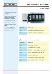
4.1 Descripción <strong>de</strong>l Panel Frontal<br />
1 2 3 4 5<br />
Figura 1.- Panel frontal.<br />
[1] Pantalla LCD.<br />
Con 2x40 caracteres <strong>de</strong> lectura fácil gracias a la retroiluminación a LEDs.<br />
[2] ERROR<br />
LED ROJO realiza dos funciones. Durante cada segundo <strong>de</strong> funcionamiento, las<br />
primeras décimas <strong>de</strong> segundo indica si el sistema está enganchado (OFF) o<br />
<strong>de</strong>senganchado (ON).<br />
Las restantes nueve décimas <strong>de</strong> segundo, el indicador luminoso en color rojo<br />
muestra si se han <strong>de</strong>tectado errores durante más <strong>de</strong> 5 segundos (ON) (<strong>de</strong>s<strong>de</strong> la<br />
última vez que el contador <strong>de</strong> errores fue reinicializado).<br />
[3] LINE<br />
LED VERDE indicador que señala cuando la alimentación está ON.<br />
[4] MENU<br />
La tecla <strong>de</strong> MENU permite al usuario entrar y salir <strong>de</strong> las funciones <strong>de</strong>l menú, así<br />
como modificar los parámetros funcionales <strong>de</strong>l equipo (parámetros <strong>de</strong> modulación,<br />
nivel y frecuencia <strong>de</strong> salida, y otras funciones <strong>de</strong> configuración).<br />
04/<strong>2008</strong> Página 15
[5] Selector rotativo y pulsador.<br />
MANUAL DE INSTRUCCIONES. <strong>MO</strong>-<strong>180</strong><br />
Posee múltiples funciones: Desplazamiento por los diferentes menús y submenús<br />
que aparecen en el monitor y validación <strong>de</strong> las distintas opciones.<br />
Cuando se pulsa el selector rotativo, y estamos modificando alguna función <strong>de</strong>l<br />
equipo, la opción que en ese momento visualice la pantalla LCD será<br />
seleccionada. Girando el selector rotativo en sentido horario (CW) o antihorario<br />
(CCW) permite navegar a través <strong>de</strong> las opciones disponibles en cada menú <strong>de</strong><br />
funciones <strong>de</strong>l <strong>MO</strong>-<strong>180</strong>.<br />
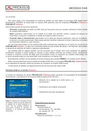
4.2 Descripción <strong>de</strong>l Panel Posterior<br />
El panel posterior muestra, <strong>de</strong> <strong>de</strong>recha a izquierda, el conector para la tensión<br />
AC <strong>de</strong> red, la rejilla <strong>de</strong>l ventilador, un conector RJ-45 para control remoto vía Ethernet,<br />
una entrada DVB-SPI TS paralela, una salida <strong>de</strong> lazo a 10 MHz GPS , una entrada <strong>de</strong><br />
10 MHz GPS, una entrada <strong>de</strong> GPS a 1 pps, dos entradas DVB-ASI TS y una salida <strong>de</strong><br />
señal FI (valor nominal 36 MHz) y la salida principal <strong>de</strong> RF, con el nivel y la frecuencia<br />
establecida por el usuario.<br />
6 7 8 9 13 14<br />
15 16<br />
Figura 2.- Vista panel posterior.<br />
[6] Salida RF, 50 Ω, conector Tipo-N hembra.<br />
[7] Salida FI, 50 Ω, BNC hembra.<br />
[8] Entrada ASI1, 75 Ω, BNC hembra.<br />
Entrada número 1 DVB-ASI.<br />
[9] Entrada ASI2, 75 Ω, BNC hembra.<br />
Entrada número 2 DVB-ASI.<br />
[10] Entrada 1PPS GPS,50 Ω alta impedancia. BNC hembra.<br />
[11] Entrada 10 MHz GPS, 50 Ω o alta impedancia. BNC hembra.<br />
[12] Salida 10 MHz GPS, BNC hembra.<br />
[13] Entrada TS paralela, DB-25.<br />
Página 16 04/<strong>2008</strong>
MANUAL DE INSTRUCCIONES. <strong>MO</strong>-<strong>180</strong><br />
[14] Entrada RJ-45 para conexiones Ethernet.<br />
[15] Conector Tensión AC.<br />
Permite la alimentación <strong>de</strong>l equipo a través <strong>de</strong> la red eléctrica.<br />
[16] Interruptor principal.<br />
Conecta o <strong>de</strong>sconecta la alimentación principal <strong>de</strong>l equipo.<br />
NOTA:<br />
El valor real <strong>de</strong> la frecuencia FI pue<strong>de</strong> variar entre 31 y 36 MHz, <strong>de</strong> acuerdo<br />
con el valor <strong>de</strong> la frecuencia RF. Cuando se precisa <strong>de</strong> una valor fijo <strong>de</strong><br />
36 MHz, el modulador <strong>de</strong>be configurarse para inhibir la salida RF, en el<br />
menú RF.<br />
4.3 Funciones <strong>de</strong>l menú.<br />
Tras la puesta en marcha, en la pantalla <strong>de</strong>l panel frontal <strong>de</strong>l equipo aparece<br />
información relativa a los principales parámetros <strong>de</strong> funcionamiento, tal como se<br />
muestra en el siguiente ejemplo:<br />
FREQ: 650000000 Hz ATT: 10 dB<br />
FFT:8K CONST:64QAM BW:8 MHz GUARD:1/4<br />
FREQ: 650000000 Hz ATT: 10 dB<br />
TEST: NONE TS: Master (204)<br />
Aquí la frecuencia RF es <strong>de</strong> 650 MHz, el atenuador RF por pasos <strong>de</strong> 1 dB ha<br />
sido ajustado a incrementos <strong>de</strong> 10 dB, la señal DVB-T contiene 8K portadoras, ocupa<br />
8 MHz y utiliza una constelación 64 QAM con intervalo <strong>de</strong> guarda <strong>de</strong> 1/4. No ha sido<br />
seleccionado ningún modo <strong>de</strong> test (NONE) y el modo <strong>de</strong> operación establecido es el<br />
modo maestro. Se han <strong>de</strong>tectado paquetes <strong>de</strong> longitud 204 bytes en la entrada TS<br />
seleccionada por el usuario.<br />
Después <strong>de</strong> unos segundos, la pantalla cambia su contenido para mostrar el<br />
tiempo <strong>de</strong> funcionamiento y la información relativa al cómputo <strong>de</strong> errores como se<br />
muestra a continuación:<br />
<strong>MO</strong>-<strong>180</strong> PROMAX ELECTRONICA, S.A.<br />
Working: 01:13:55 ERR: 0<br />
El texto <strong>de</strong> la línea superior (nombre <strong>de</strong> la compañía por ejemplo) pue<strong>de</strong> ser<br />
modificada vía puerto <strong>de</strong> control remoto según las necesida<strong>de</strong>s <strong>de</strong> cada usuario,<br />
permitiendo fácilmente una i<strong>de</strong>ntificación o aviso <strong>de</strong>l equipo.<br />
Cada 5 segundos en el display se muestra alternamente la información anterior<br />
y la siguiente.<br />
TS SPI: 19.423 Mbps<br />
Working: 01:14:12 ERR: 0<br />
04/<strong>2008</strong> Página 17
MANUAL DE INSTRUCCIONES. <strong>MO</strong>-<strong>180</strong><br />
Esta representa una estimación <strong>de</strong> la velocidad binaria <strong>de</strong> una trama <strong>de</strong><br />
transporte seleccionada <strong>de</strong> la red. Es <strong>de</strong>cir, que si trabajamos en modo esclavo o SFN<br />
esta es directamente la velocidad binaria total que llega al modulador <strong>de</strong> la entrada TS.<br />
Cuando trabajamos en modo master, MFN, esta es la velocidad binaria <strong>de</strong> una TS<br />
proce<strong>de</strong>nte <strong>de</strong> eliminar todos los paquetes no válidos. En el caso <strong>de</strong> que la entrada<br />
solo tenga paquetes erróneos, la velocidad binaria estimada será <strong>de</strong> 0 Mbps. La<br />
velocidad estimada se expresa en Mbps con tres <strong>de</strong>cimales, con una resolución <strong>de</strong><br />
1Kbps por ejemplo.<br />
Pulsando la tecla MENU, permite acce<strong>de</strong>r al nivel principal <strong>de</strong>l menú. Pulsar<br />
MENU <strong>de</strong> nuevo para acce<strong>de</strong>r a la pantalla principal <strong>de</strong> estado. Este nivel principal <strong>de</strong>l<br />
menú utiliza la primera línea <strong>de</strong> texto para proporcionar algunos avisos a cerca <strong>de</strong> las<br />
operaciones asignadas a cada control, y la segunda línea <strong>de</strong> la pantalla sobre las<br />
opciones y funciones seleccionables.<br />
19.<br />
MENU: back PUSH: select TURN: next/prev.<br />
<strong>MO</strong>DULATOR<br />
Al girar el selector rotativo CW o CCW, cambia el título <strong>de</strong>l submenú.<br />
El menú 3 está organizado jerárquicamente como muestra la tabla <strong>de</strong> la página<br />
Página 18 04/<strong>2008</strong>
MANUAL DE INSTRUCCIONES. <strong>MO</strong>-<strong>180</strong><br />
TS SPI: 19.432Mbps<br />
Working: 01:14:12 ERR: 0<br />
CONFIGURATION STATUS<br />
TEST<br />
RF LEVEL<br />
SYNC FILTERING<br />
NETWORK<br />
<strong>MO</strong>DULATOR<br />
Error List:<br />
Access to error list<br />
Save to Memory:<br />
0 – 10<br />
Mo<strong>de</strong>:<br />
NO NE , CBE R, VB ER,<br />
Blank Carriers, Pilots only,<br />
PRBS/TR-290<br />
Attenuation:<br />
0 to 60 dB in 1-dB steps<br />
Frequency (1-Hz res.):<br />
45,000, 000 to 875, 000,000<br />
Mo<strong>de</strong>: OFF, ON<br />
10MHz reference:<br />
Int, Ext, Auto1, Auto2<br />
Mo<strong>de</strong>: MFN, SFN<br />
HP/LP TS Input:<br />
ASI1, ASI2, SPI, PRBS<br />
PID 01: 1 − 8191<br />
Clear Errors:<br />
NO , YE S<br />
Load from Memory:<br />
0 – 10<br />
Fine Adjust :<br />
–31 t o +32<br />
Channel:<br />
Number from Channel Plan<br />
10MHz Zin: High, 50 ohm<br />
Modulator Config.:<br />
Local, MIP<br />
BW (MHz): 8, 7, 6, 5<br />
Start Carrier:<br />
Valid carrier in<strong>de</strong>x<br />
PID 02: 1 − 8191<br />
SW/FW/OPT:<br />
Current Equipment Config.<br />
Channel Plan:<br />
CCIR, STD L, OIRT, UHF<br />
NLPD Mo<strong>de</strong>:<br />
OFF, ON<br />
Disable:<br />
NO, YES<br />
1pps edge: Rise, Fall<br />
Local dly offset:<br />
Value in microseconds<br />
Hierarchy:<br />
OFF, Alpha = 1, 2, 4<br />
Stop Carrier:<br />
Valid carrier in<strong>de</strong>x<br />
1pps Zin: High, 50 ohm<br />
MIP Loss :<br />
None, HP, LP, HP&LP<br />
IF Mo<strong>de</strong>:<br />
COFDM, Tone MAX or RMS<br />
CFR Mo<strong>de</strong>:<br />
OFF, ON<br />
. .<br />
.<br />
Transmitter ID:<br />
1 − 65535<br />
HP/LP co<strong>de</strong> rate:<br />
1/ 2, 2/3, 3/4, 5/6, 7/8<br />
PID 15: 1 − 8191<br />
.<br />
.<br />
.<br />
CBER value :<br />
MIP Error:<br />
None, HP, LP, HP&LP<br />
IP Address:<br />
Valid number<br />
CFR V alue:<br />
8 to 11 dB in 0. 1-dB steps<br />
Network ID:<br />
0 − 65535<br />
Constellation:<br />
QPSK, 16QAM, 64QAM<br />
PID 16: 1 − 8191<br />
VBER value:<br />
1pps Error:<br />
OFF, ON<br />
IP Mask:<br />
Valid number<br />
Update Net ID:<br />
OFF, ON<br />
Guard Interval:<br />
1/ 4,, 1/8, 1/16, 1/32<br />
04/<strong>2008</strong> Página 19<br />
Tx Frequency Offset:<br />
Value in Hz<br />
Gateway IP:<br />
Valid value<br />
Centre Frequency:<br />
Frequency in 10 Hz steps<br />
FFT Mo<strong>de</strong>: 2k, 8k, 4k<br />
Tx Radia ted Powe r:<br />
Value in dBm<br />
Update Centre Freq.:<br />
OFF, ON<br />
Spectral Inversion:<br />
ON, OFF<br />
PRBS bits: 23, 15<br />
HP/LP Net Delay:<br />
Value in microseconds<br />
TS sync mo<strong>de</strong>:<br />
Master, Slave<br />
Tx Tim e Offset:<br />
Value in ms<br />
Slave mo<strong>de</strong> TS lock:<br />
HP, LP<br />
Maximum Delay:<br />
Value in microseconds<br />
Cell ID: 0 − 65535<br />
NIT Netw ork ID:<br />
Valid NIT ID<br />
Mo<strong>de</strong>: DVB-T, DV B-H<br />
HP TS ID:<br />
Valid TS ID<br />
COLOUR KEY<br />
DVB-H only<br />
MFN only<br />
SFN only<br />
MPE-FEC:<br />
OFF, HP, LP, HP&LP<br />
Time Slicing:<br />
OFF, HP, LP, HP&LP<br />
Symbol Interl.:<br />
Native, In-<strong>de</strong>pth
4.4 Funciones <strong>de</strong>l <strong>MO</strong>DULADOR<br />
MANUAL DE INSTRUCCIONES. <strong>MO</strong>-<strong>180</strong><br />
En este nivel <strong>de</strong>l menú, los parámetros <strong>de</strong>l modulador pue<strong>de</strong>n ser modificados<br />
y ajustados según los requisitos <strong>de</strong>l usuario. Al modificar cualquier parámetro <strong>de</strong><br />
modulación, los cambios se activan sólo cuando se confirman pulsando el selector<br />
rotativo. Por el contrario, pulsando la tecla <strong>de</strong> MENU, se cancela el cambio <strong>de</strong> la<br />
opción. A continuación se comenta cada función (Pulsar tecla menú para entrar:<br />
“<strong>MO</strong>DULATOR”):<br />
TS HP Input<br />
Permite seleccionar la entrada utilizada para suministrar el Transport Stream<br />
(TS) <strong>de</strong> alta prioridad al modulador COFDM. Las opciones son:<br />
ASI1: Utiliza el TS suministrado por el conector <strong>de</strong> entrada ASI1 (panel<br />
posterior).<br />
ASI2: Utiliza el TS suministrado por el conector <strong>de</strong> entrada ASI2 (panel<br />
posterior).<br />
SPI: Utiliza el TS paralelo suministrado por el conector SPI (panel posterior).<br />
PRBS: Test TS interno con una velocidad binaria a<strong>de</strong>cuada. Consiste en una<br />
secuencia <strong>de</strong> paquetes PRBS NULL compuestos <strong>de</strong> 15 o 23 bits según<br />
indica pulsando la tecla menú “ Modulator: PRBS bits”<br />
TS LP Input<br />
Permite seleccionar la entrada utilizada para suministrar el Transport Stream<br />
(TS) <strong>de</strong> baja prioridad al modulador COFDM. Las opciones son:<br />
BW<br />
ASI1: Utiliza el TS suministrado por el conector <strong>de</strong> entrada ASI1 (panel<br />
posterior).<br />
ASI2: Utiliza el TS suministrado por el conector <strong>de</strong> entrada ASI2 (panel<br />
posterior).<br />
SPI: Utiliza el TS paralelo suministrado por el conector SPI (panel posterior).<br />
PRBS: Test TS interno con una velocidad binaria a<strong>de</strong>cuada. Consiste en una<br />
secuencia <strong>de</strong> paquetes PRBS NULL compuestos <strong>de</strong> 15 o 23 bits según<br />
indica pulsando la tecla menú “ Modulator: PRBS bits”<br />
Esta opción habilita la selección <strong>de</strong>l ancho <strong>de</strong> banda. La señal COFDM pue<strong>de</strong><br />
ser generada con un ancho <strong>de</strong> banda <strong>de</strong> 6 MHz, 7 MHz ó 8 MHz. En DVB-H<br />
(“ <strong>MO</strong>DULATO:Mo<strong>de</strong>” seleccionado para DVB-H) po<strong>de</strong>mos escoger otra opción más<br />
<strong>de</strong> 5 MHz.<br />
Página 20 04/<strong>2008</strong>
MANUAL DE INSTRUCCIONES. <strong>MO</strong>-<strong>180</strong><br />
Hierarchy<br />
8 MHz: Selecciona el ancho <strong>de</strong> banda <strong>de</strong> 8 MHz.<br />
7 MHz: Selecciona el ancho <strong>de</strong> banda <strong>de</strong> 7 MHz.<br />
6 MHz: Para un ancho <strong>de</strong> banda <strong>de</strong> 6 MHz.<br />
5 MHz: Para un ancho <strong>de</strong> banda <strong>de</strong> 5 MHz (Sólo para DVB-H).<br />
Utilizando esta función el modulador COFDM conmuta entre modo jerárquico,<br />
con diferentes ratios <strong>de</strong> constelación alfa, y el modo <strong>de</strong> funcionamiento no jerárquico.<br />
Las opciones disponibles son:<br />
OFF: Funcionamiento no jerárquico.<br />
a=1: Constelación jerárquica con alfa = 1.<br />
a=2: Constelación jerárquica con alfa = 2.<br />
a=4: Constelación jerárquica con alfa = 4.<br />
HP Co<strong>de</strong> Rate<br />
Utilizando esta función, el usuario pue<strong>de</strong> modificar la tasa <strong>de</strong> código <strong>de</strong><br />
modulación para los flujos <strong>de</strong> datos (TS) <strong>de</strong> alta prioridad (HP). Las opciones<br />
disponibles son las siguientes:<br />
1/2<br />
2/3<br />
3/4<br />
5/6<br />
7/8<br />
LP Co<strong>de</strong> Rate<br />
Utilizando esta función, el usuario pue<strong>de</strong> modificar la tasa <strong>de</strong> código <strong>de</strong><br />
modulación para los flujos <strong>de</strong> datos (TS) <strong>de</strong> baja prioridad (LP). Las opciones<br />
disponibles son las siguientes:<br />
1/2<br />
2/3<br />
3/4<br />
5/6<br />
7/8<br />
04/<strong>2008</strong> Página 21
Constellation<br />
MANUAL DE INSTRUCCIONES. <strong>MO</strong>-<strong>180</strong><br />
Aquí el menú permite seleccionar una <strong>de</strong> las constelaciones <strong>de</strong> modulación<br />
disponibles. Las opciones son:<br />
QPSK<br />
16QAM<br />
64QAM<br />
Guard Interval<br />
Esta función se utiliza para seleccionar el intervalo <strong>de</strong> guarda requerido <strong>de</strong> la<br />
señal COFDM. Los valores disponibles son:<br />
1/4<br />
1/8<br />
1/16<br />
1/32<br />
FFT Mo<strong>de</strong><br />
Selección <strong>de</strong>l valor FFT requerido (número <strong>de</strong> portadoras en el conjunto<br />
COFDM). El modulador tiene las siguientes opciones:<br />
2K 2048 portadoras, 1705 activas.<br />
8K 8192 portadoras, 6817 activas.<br />
4K 4096 portadoras, 3409 activas. Sólo para DVB-H( El menú<br />
“<strong>MO</strong>DULATOR:Mo<strong>de</strong>” ,<strong>de</strong>be estar seleccionado DVB-H).<br />
Spectral Inversión<br />
Esta función permite realizar la inversión <strong>de</strong>l espectro generado tanto para la FI<br />
como en RF. Dado que el espectro FI está invertido en comparación con la salida RF,<br />
el concepto <strong>de</strong> inversión se refiere a la salida RF. Las opciones posibles son:<br />
OFF: Las portadoras con los índices menores ocupan las frecuencias más<br />
bajas <strong>de</strong>l canal RF.<br />
ON: Las portadoras con los índices mayores ocupan las frecuencias más<br />
bajas <strong>de</strong>l canal RF.<br />
Página 22 04/<strong>2008</strong>
MANUAL DE INSTRUCCIONES. <strong>MO</strong>-<strong>180</strong><br />
PRBS bits<br />
Selección <strong>de</strong> la longitud en bits <strong>de</strong> la secuencia pseudoaleatoria que genera<br />
internamente:<br />
23: Secuencia PRBS <strong>de</strong> longitud 2²³-1 como se documenta en el TR 101<br />
290.<br />
15: Secuencia PRBS <strong>de</strong> longitud 2¹ 5-1 como se documenta en el TR 101<br />
290.<br />
TS sync mo<strong>de</strong><br />
En modo MFN, selecciona el modo <strong>de</strong> operación <strong>de</strong>l modulador respecto a la<br />
entrada TS( ver sección 1.2 para más <strong>de</strong>talle).<br />
Master: La velocidad binaria <strong>de</strong> la entrada <strong>de</strong>be ser más pequeña que la<br />
velocidad utilizada para los parámetros <strong>de</strong> DVB-T en uso.<br />
Slave: La velocidad binaria <strong>de</strong> entrada <strong>de</strong>be ser igual a la velocidad binaria en<br />
uso.<br />
Slave mo<strong>de</strong> TS lock<br />
En modo esclavo, selecciona la entrada TS respecto a la que el modulador<br />
sincroniza su reloj interno. Las opciones posibles son:<br />
Cell ID<br />
HP: El modulador está sincronizado con el TS HP.<br />
LP: El modulador está sincronizado con el TS LP (sólo modos jerárquicos).<br />
Asignando un número <strong>de</strong> 0 a 65535 conseguimos i<strong>de</strong>ntificar la celda <strong>de</strong>s<strong>de</strong><br />
don<strong>de</strong> proviene la señal DVB-T/H. Esto es fundamental en DVB-H pero opcional en<br />
DVB-T.<br />
Mo<strong>de</strong><br />
Las propieda<strong>de</strong>s <strong>de</strong> DVB-H sólo se pue<strong>de</strong>n usar y están activadas mediante el<br />
menú System, cuando el indicador <strong>de</strong> longitud TPS está seleccionado a 33 bits. No<br />
obstante el DVB-T es usado como un marcador por el indicador <strong>de</strong> longitud TPS<br />
siendo 31 bits. En DVB-H los dos bits extras indican el uso <strong>de</strong>l Time slicing y MPE-<br />
FEC. Las opciones son:<br />
DVB-T (31 TPS bits) Modo DVB-T con longitud <strong>de</strong> indicador TPS <strong>de</strong> 31 bits.<br />
DVB-H (33 TPS bits) Modo DVB-H con longitud <strong>de</strong> indicador TPS <strong>de</strong> 33.<br />
04/<strong>2008</strong> Página 23
MPE-FEC<br />
MANUAL DE INSTRUCCIONES. <strong>MO</strong>-<strong>180</strong><br />
En DVB-H, esta opción configura el Multi-Protocol Encapsulation / Forward<br />
Error Correction (MPE-FEC) que es usado en la codificación <strong>de</strong> canal <strong>de</strong> DVB-T: Las<br />
opciones disponibles son:<br />
OFF MPE-FEC no usado.<br />
HP HP TS usa MPE-FEC.<br />
LP LP TS usa MPE-FEC<br />
HP&LP HP TS y LP TS usan MPE-FEC.<br />
Time Slicing<br />
En DVB-H indica las tramas <strong>de</strong> transporte tanto en HP o LP usan el time<br />
slicing.<br />
OFF Time slicing no usado.<br />
HP Por lo menos una TS básica sin HP TS usa time slicing.<br />
LP Por lo menos una TS básica sin LP TS usa time slicing.<br />
HP&LP Por lo menos una trama básica sin HP y LP TS’s usa time slicing.<br />
Symbol Interl.<br />
En DVB-H, este selecciona el propio symbol interleaver entre 2k y 4k y el<br />
DVB-H-only in-<strong>de</strong>pth symbol interleaver. Para 8k, el iterleaver nativo es obligatorio.<br />
Native: Obligatorio en DVB-T y DVB-H con 8k<br />
In-<strong>de</strong>pth: Introduce un nuevo símbolo en modo DVB-H 2k y 4K.<br />
4.5 Funciones <strong>de</strong> Red (NETWORK)<br />
La selección <strong>de</strong> este ítem permite el acceso a las funciones relacionadas con la<br />
configuración <strong>de</strong>l modulador para funcionar en una red MFN o SFN. Permítannos<br />
repasar cada opción.<br />
Mo<strong>de</strong><br />
Escoja si el modulador va a ser usado en una red <strong>de</strong> una sola frecuencia (SFN)<br />
o en una red <strong>de</strong> múltiple frecuencias (MFN). En una red SFN el modulador sincroniza<br />
su reloj interno con una referencia externa a 10 MHz o con la entrada HP transport<br />
stream en el caso <strong>de</strong> que la referencia externa falle. La sincronización apropiada<br />
requiere un Megaframe Initialization Packet (MIP) en la TS entrante ( o en ambas<br />
tramas <strong>de</strong> transporte en el caso <strong>de</strong> transmisiones jerárquicas) y una referencia <strong>de</strong> un<br />
pulso por segundo 1pps. En un MFN, el modulador es sincronizado con las TS<br />
escogidas <strong>de</strong> entrada o con a referencia <strong>de</strong> 10 MHz interna o externa (Modo Master).<br />
Página 24 04/<strong>2008</strong>
MANUAL DE INSTRUCCIONES. <strong>MO</strong>-<strong>180</strong><br />
MFN Red multifrecuencia con sincronización master o esclava.<br />
SFN Red <strong>de</strong> una sola frecuencia con sincronización externa.<br />
Modulator Config<br />
Algunos parámetros <strong>de</strong>l modulador (Constelación, símbolo interleaver, modos<br />
<strong>de</strong> jerarquía con parámetros alpha, tasa convolucionales HP & LP, intervalos <strong>de</strong><br />
guarda, números <strong>de</strong> portadoras, time slicing, MPE-FEC, Cell ID y ancho <strong>de</strong> banda <strong>de</strong>l<br />
canal), se pue<strong>de</strong>n configurar usando valores se transportan en los paquetes MIP. Esto<br />
es aplicable tanto a MFN o SFN.<br />
Local: Configura el modulador usando los valores incorporados por el usuario.<br />
MIP: Configura el modulador usando los paquetes MIP<br />
Local dly offset<br />
En MFN, este es el offset <strong>de</strong> retraso no-negativo añadido a la latencia<br />
intrínseca Tel. modulador. El rango validaba <strong>de</strong>s<strong>de</strong> unos pocos ms ( el número exacto<br />
<strong>de</strong>pen<strong>de</strong> <strong>de</strong>l ancho <strong>de</strong> banda <strong>de</strong>l canal, el número <strong>de</strong> portadoras, el intervalo <strong>de</strong><br />
guarda y el symbol interleaver <strong>de</strong>pth ) y pue<strong>de</strong> llegar a 1sg. En modo SFN, este offset<br />
local pue<strong>de</strong> ser positivo o negativo y lo añadimos la retraso dinámico calculado<br />
automáticamente por el modulador usando los MIP,la señal <strong>de</strong>1 pps y la referencia <strong>de</strong><br />
clock <strong>de</strong> 10 MHz. El rango válido para este offse en SFN es tanto como el retraso total<br />
( Calculado como el retraso dinámico más el retraso local mas el retraso <strong>de</strong><br />
transmisión icluido en los MIP), pue<strong>de</strong> ser <strong>de</strong>s<strong>de</strong> unos poco ms a 1sg. El retraso<br />
mínimo <strong>de</strong>pen<strong>de</strong> <strong>de</strong> los mismos parámetros que en MFN. Cuando el retraso total es<br />
menor que el mínimo o mayor que el máximo (aunque este sea recortado a 1sg), el<br />
modulador mostrará un error. El retraso local pue<strong>de</strong> ser fijado con una resolución <strong>de</strong><br />
100 ns.<br />
Transmitter ID<br />
Este número i<strong>de</strong>ntifica a un transmisor único <strong>de</strong>ntro <strong>de</strong> una red SFN o MFN.<br />
Esta ID pue<strong>de</strong> ser usada en combinación <strong>de</strong> los paquetes MIP para direccionar a un<br />
transmisor específico para po<strong>de</strong>r configurar algunos parámetros ( tales como un timpo<br />
<strong>de</strong> offset <strong>de</strong> retraso, offset en la frecuencia RF, potencia <strong>de</strong> radiación, datos privados<br />
<strong>de</strong>finidos por el usuario, cell ID, ancho <strong>de</strong> banda, otros que 6,7 y 8 MHz), sin importar<br />
cual pue<strong>de</strong> ser la configuración para el resto <strong>de</strong> la red. Una ID igual a 0 hace<br />
referencia a todos los transmisores y <strong>de</strong> esta forma no po<strong>de</strong>mos i<strong>de</strong>ntificar al<br />
transmisor.<br />
04/<strong>2008</strong> Página 25
Network ID<br />
MANUAL DE INSTRUCCIONES. <strong>MO</strong>-<strong>180</strong><br />
Este número es el único código <strong>de</strong> i<strong>de</strong>ntificación para re<strong>de</strong>s DTT. La asignación<br />
<strong>de</strong> estos códigos pue<strong>de</strong> encontrarse en el documento ETSI ETR 162. Cuando<br />
“NETWORK: Update NET ID” está activado, la ID <strong>de</strong> la red en la tabla NIT actual (es<br />
<strong>de</strong>cir, que el NIT es parte <strong>de</strong> las TS que contiene la red ) se sustituye con la ID <strong>de</strong> red<br />
especificada aquí. El CRC <strong>de</strong> la tabla NIT es actualizada y por consiguiente su número<br />
<strong>de</strong> versión es incrementado en 1.<br />
Update Net. ID<br />
Las dos opciones disponibles son ON y OFF. Cuando está seleccionado ON, el<br />
campo network_id que se encuentra en la NIT <strong>de</strong> la actual red (NIT con table_id=0x40)<br />
es remplazado con la ID <strong>de</strong> red especificada pulsando la tecla menú<br />
”NETWORK:Network ID”<br />
Centre Frequency<br />
Esta representa la frecuencia central que sustituye el valor salvado actualmente<br />
en el NIT cuando “NETWORK:Update Centre Freq.” esta en ON. Esta frecuencia está<br />
expresada en unida<strong>de</strong>s <strong>de</strong> 10Hz.<br />
Update Centre Freq<br />
Cuando esta entrada está activada (ON), los 32-bits <strong>de</strong>la frecuencia central y<br />
los campos <strong>de</strong> frecuencia encontrados <strong>de</strong>ntro <strong>de</strong> los NIT <strong>de</strong>scriptor<br />
terrestrial_<strong>de</strong>livery_system_<strong>de</strong>scriptor y cell_frequency_linl_<strong>de</strong>scriptor,<br />
respectivamente, <strong>de</strong> la actual red ( NIT con tabla ID=0x40) son reemplazados por el<br />
valor especificado pulsando la tecla menú “ NETWORK:Centre Frequency”. El campo<br />
entrante <strong>de</strong> 32-bit CRC y la versión NIT son actualizadas conjuntamente. Observe que<br />
para el <strong>de</strong>scriptor cell_frequency_link_<strong>de</strong>scriptor (que contienen una lista completa <strong>de</strong><br />
Cell Ids y frecuencias en uso en estas celdas para el multiplex <strong>de</strong> los TS <strong>de</strong>scrito)<br />
emparejaremos la frecuencia central con la cell ID que está siendo difundida usando<br />
los bits TPS. Esa Cell ID pue<strong>de</strong> ser sucesivamente cualquiera <strong>de</strong> las extraídas <strong>de</strong> los<br />
paquetes MIP o alternativamente una <strong>de</strong>finida entrando en el menú “<strong>MO</strong>DULATOR :<br />
Cell ID”<br />
4.6 Funciones SYNC<br />
Este conjunto <strong>de</strong> funciones controlan todas las características <strong>de</strong> sincronismo<br />
<strong>de</strong>l <strong>MO</strong>-<strong>180</strong>. A continuación se <strong>de</strong>tallan las opciones disponibles <strong>de</strong>l menú.<br />
100 MHz Reference<br />
Esta se aplica tanto operaciones MFN como SFN. En modo MFN esclavo el<br />
reloj <strong>de</strong>l modulador está siempre <strong>de</strong>rivado hacia la entrada TS rate. Se <strong>de</strong>finen varios<br />
modos <strong>de</strong> sincronismo.<br />
Página 26 04/<strong>2008</strong>
MANUAL DE INSTRUCCIONES. <strong>MO</strong>-<strong>180</strong><br />
Ext SFN y master MFN. El modulador engancha su circuitería a la entrada<br />
<strong>de</strong> 10 MHz. Este pue<strong>de</strong> ser por ejemplo el reloj obtenido <strong>de</strong> la señal<br />
GPS proporcionada por un receptor GPS profesional externo.<br />
Int Sólo para MFN. Usa el TCXO <strong>de</strong> 10 MHz interno para la sincronización.<br />
Auto 1 Solo para MFN. El interruptor automático cambia <strong>de</strong> la referencia<br />
externa <strong>de</strong> 10 MHz (tipo 1 por <strong>de</strong>fecto) a la interna TCXO cuando la<br />
referencia externa se ha perdido. Una vez que la referencia externa <strong>de</strong><br />
10 MHz perdida ha sido enganchada, se cambia hacia el clock interno<br />
<strong>de</strong> 10 MHz, el indicador <strong>de</strong> la pérdida <strong>de</strong> sincronismo <strong>de</strong> 10 MHz<br />
permanecerá encendido hasta se seleccione <strong>de</strong> nuevo Auto 1.<br />
Auto 2 SFN y MFN master. El conmutador automático, tipo 2, tiene un<br />
funcionamiento similar al tipo 1. La única diferencia es que cuando se<br />
pier<strong>de</strong> el sincronismo, el interruptor cambia a un reloj <strong>de</strong>rivado <strong>de</strong> los<br />
datos <strong>de</strong> la TS, el cual se encuentra en las tramas entrantes HP como<br />
MFN esclavo.<br />
100 MHz Zin<br />
La impedancia vista <strong>de</strong>s<strong>de</strong> el conector BNC <strong>de</strong> 10 MHz pue<strong>de</strong> ser 50 Ω o alta<br />
impedancia (varios MΩ)<br />
1pps edge<br />
Cuando trabajamos en SFN está activa la señal <strong>de</strong> un pulso por segundo.<br />
Generalmente se usa el flanco <strong>de</strong> subida.<br />
1pps Zin<br />
Cuando trabajamos en modo SFN, la impedancia vista <strong>de</strong>s<strong>de</strong> el conector BNC<br />
<strong>de</strong> 1pps pue<strong>de</strong> ser 50 Ω o High Z.<br />
4.7 Funciones <strong>de</strong> filtrado (Filtering)<br />
La i<strong>de</strong>ntificación <strong>de</strong> los paquetes filtrados pue<strong>de</strong> ser usada en una red MFN<br />
para reducir la velocidad binaria <strong>de</strong> una TS entrante para ajustar esta a la velocidad<br />
binaria con la cual el modulador es capaz <strong>de</strong> trabajar en un menú particular <strong>de</strong><br />
DVB-T/H.<br />
Cada programa <strong>de</strong> trama elemental (PES, Program elementary Stream) que<br />
pertenecen a una TS multiplex y contienen vi<strong>de</strong>o, audio o datos son i<strong>de</strong>ntificado por un<br />
único PID. El <strong>MO</strong>-<strong>180</strong> permite al usuario eliminar hasta 16 PES’s <strong>de</strong> la TS. Observe<br />
que una TS <strong>de</strong> MPEG-2 no está realmente multiplexada porque en las tablas <strong>de</strong><br />
información <strong>de</strong>l sistema no están actualizadas. Sólo los PES’s ayudan a reducir la<br />
velocidad binaria. Esta característica se encuentra incluida en nuestra aplicación. Por<br />
ejemplo, cuando realizamos una Trans-modulación con alta velocidad binaria, señal<br />
DVB-S o DVB-C a señal DVB-T/H<br />
04/<strong>2008</strong> Página 27
Mo<strong>de</strong><br />
PID 01-16<br />
MANUAL DE INSTRUCCIONES. <strong>MO</strong>-<strong>180</strong><br />
Seleccione ON para activar el filtrado PID o OFF para <strong>de</strong>sactivarlo.<br />
En la entrada <strong>de</strong> TS hasta 16 PIDs pue<strong>de</strong>n ser <strong>de</strong>scartados. Observe que la<br />
búsqueda <strong>de</strong> PID es aplicada a las dos entradas HP y LP. El rango <strong>de</strong> <strong>de</strong>cimales<br />
válido es <strong>de</strong> 1 a 8191. El PID=0 está reservado para el programa <strong>de</strong> asociación <strong>de</strong><br />
tabla (PAT) y no pue<strong>de</strong> ser eliminado.<br />
4.8 Funciones RF<br />
La selección <strong>de</strong> este ítem permite acce<strong>de</strong>r a las funciones relativas a la salida<br />
RF. A continuación se repasan las opciones disponibles:<br />
Frecuencia<br />
Esta función permite la selección <strong>de</strong> la frecuencia RF. Los cambios realizados<br />
mediante el selector rotativo se aplican directamente a la salida, permitiendo una<br />
sintonización precisa <strong>de</strong> la frecuencia <strong>de</strong> salida <strong>de</strong>seada.<br />
Al acce<strong>de</strong>r a la función, la pantalla muestra la frecuencia actual y la variación<br />
que se introduce al modificarla cuando se gira el selector rotativo. Los pasos <strong>de</strong><br />
frecuencia son increméntales al girar el selector rotativo en sentido horario y<br />
<strong>de</strong>crementales al girarlo en sentido antihorario.<br />
MENU: back PUSH: select TURN: next/prev.<br />
RF Frequency: 650000000 Hz <br />
En este caso, la frecuencia <strong>de</strong> salida actual es <strong>de</strong> 650 MHz y girando un paso<br />
en sentido horario (cada paso se señala mediante un tono acústico) cambiará el valor<br />
a 660 MHz.<br />
En esta situación, cada vez que se pulse el selector rotativo, el paso <strong>de</strong><br />
variación <strong>de</strong> frecuencia se modificará <strong>de</strong> 1 MHz, 100 kHz, 10 kHz, 1 kHz, 100 Hz,<br />
10 Hz, 1 Hz y otra vez 10 MHz, <strong>de</strong> forma cíclica permitiendo la selección <strong>de</strong>l valor<br />
<strong>de</strong>seado.<br />
Channel<br />
Para abandonar esta función, se <strong>de</strong>be pulsar la tecla MENU.<br />
Una sintonización rápida <strong>de</strong> la frecuencia <strong>de</strong> salida pue<strong>de</strong> realizarse utilizando<br />
el conjunto <strong>de</strong> listas <strong>de</strong> canales incluidas en el <strong>MO</strong>-<strong>180</strong>. Esto permite la selección<br />
directa <strong>de</strong> las frecuencias estándar utilizadas en la mayoría <strong>de</strong> países.<br />
Página 28 04/<strong>2008</strong>
MANUAL DE INSTRUCCIONES. <strong>MO</strong>-<strong>180</strong><br />
Al acce<strong>de</strong>r a esta función, se visualiza secuencialmente la lista <strong>de</strong> todos los<br />
canales disponibles. Girando el selector rotativo se pue<strong>de</strong> seleccionar el que se <strong>de</strong>see.<br />
Pulsar el selector para abandonar la función.<br />
La lista <strong>de</strong> canales se seleccionan a partir <strong>de</strong>l conjunto <strong>de</strong> listas <strong>de</strong> canales ya<br />
incluidas en el equipo. Las listas <strong>de</strong> canales disponibles se visualizan y seleccionan<br />
<strong>de</strong>s<strong>de</strong> el menú CONFIGURACIÓN, como se verá más a<strong>de</strong>lante.<br />
También en este caso, los cambios <strong>de</strong> frecuencia se aplican inmediatamente a<br />
la etapa RF, permitiendo un ajuste interactivo <strong>de</strong> la frecuencia.<br />
Disable<br />
Esta lista <strong>de</strong> planes <strong>de</strong> canales pue<strong>de</strong> ser consultada en el apéndice A.<br />
Esta opción permite <strong>de</strong>shabilitar la salida <strong>de</strong> RF. Esto se consigue<br />
introduciendo una fuerte atenuación (aproximadamente 80 dB) en la señal RF.<br />
Simultáneamente, la frecuencia FI se sintoniza al valor nominal <strong>de</strong> 36 MHz. Los<br />
valores seleccionables son:<br />
NO Habilita la salida RF.<br />
YES Deshabilita la salida RF.<br />
4.9 Funciones <strong>de</strong> Nivel (Level)<br />
Esta opción <strong>de</strong>l menú principal incluye las funciones relativas al ajuste <strong>de</strong>l nivel<br />
<strong>de</strong> RF. El <strong>MO</strong>-<strong>180</strong> cuenta con un atenuador programable integrado <strong>de</strong> 60 dB en pasos<br />
<strong>de</strong> 1 dB. Simultáneamente el nivel <strong>de</strong> RF nominal pue<strong>de</strong> ser ajustado con <strong>de</strong>talle<br />
mediante el control <strong>de</strong> ganancia <strong>de</strong>l amplificador RF, aplicando los incrementos <strong>de</strong> 1<br />
dB <strong>de</strong> la atenuación a partir <strong>de</strong>l valor <strong>de</strong> referencia.<br />
También po<strong>de</strong>mos encontrar incluidos en esta sección los controles <strong>de</strong>,<br />
Reducción <strong>de</strong>l factor Cresta y la etapa <strong>de</strong>l predistorsionador no lineal.<br />
La estructura <strong>de</strong> ganancia RF pue<strong>de</strong> ser controlada mediante las siguientes<br />
funciones.<br />
Attenuatión<br />
Esta función permite seleccionar el nivel <strong>de</strong> salida RF aplicando pasos <strong>de</strong><br />
atenuación <strong>de</strong> 1 dB, <strong>de</strong>s<strong>de</strong> 0 dB hasta 60 dB. Girando el selector rotativo en sentido<br />
horario se incrementa la atenuación, reduciendo el nivel <strong>de</strong> salida. Girando en sentido<br />
antihorario produce el efecto contrario.<br />
Los cambios son aplicados <strong>de</strong> forma inmediata a la salida RF para facilitar un<br />
ajuste sencillo y preciso. Pulsar el selector rotativo o la tecla MENU para abandonar<br />
esta función.<br />
04/<strong>2008</strong> Página 29
Fine Adjust<br />
MANUAL DE INSTRUCCIONES. <strong>MO</strong>-<strong>180</strong><br />
Seleccionar esta función para programar el nivel <strong>de</strong> referencia <strong>de</strong> la salida RF.<br />
Para una correcta referencia, ajustar la atenuación <strong>de</strong> salida a 0 dB, antes <strong>de</strong> modificar<br />
este ajuste.<br />
Los cambios también se aplican en tiempo real. Girar el selector rotativo en<br />
sentido horario para incrementar el nivel <strong>de</strong> salida. Girar en sentido antihorario para<br />
disminuir el nivel.<br />
Los caracteres visualizados son números enteros. El margen oscila entre un<br />
valor máximo <strong>de</strong> atenuación <strong>de</strong> —31 hasta un valor mínimo <strong>de</strong> atenuación <strong>de</strong> +31 (es<br />
<strong>de</strong>cir, <strong>de</strong>s<strong>de</strong> 0 hasta 63 pasos <strong>de</strong> atenuación).<br />
Para salir <strong>de</strong> esta función, pulsar la tecla <strong>de</strong> MENU o el selector rotativo.<br />
4.9.1 Funciones predistorsión no lineal, modo NLPD.<br />
El bloque <strong>de</strong> pre-distorsión no lineal (NPLD) está activo cuando esta<br />
entradas fijada a ON.<br />
El bloque NPLD usa un sistema <strong>de</strong> 2 a 16 puntos para aproximar linealmente la<br />
compleja curva <strong>de</strong> ganancia. Esta es usada para contrarrestar las características<br />
AM/AM y AM/PM <strong>de</strong>l amplificador <strong>de</strong> potencia <strong>de</strong> la RF. La curva AM/AM <strong>de</strong>fine la<br />
amplitud <strong>de</strong> distorsión que el amplificador introduce en función <strong>de</strong> la potencia <strong>de</strong><br />
entrada. La curva AM/PM <strong>de</strong>fine la distorsión <strong>de</strong> fase que el amplificador causa en<br />
función <strong>de</strong> la potencia <strong>de</strong> entrada.<br />
La corrección <strong>de</strong> ganancia es compleja. Para un punto n-th pue<strong>de</strong> ser<br />
expresada <strong>de</strong> la siguiente forma.<br />
g = ℜ g ) + jℑ(<br />
g ) = g exp( jθ<br />
)<br />
n<br />
( n<br />
n n<br />
n<br />
Con n = 0...15. La amplitud <strong>de</strong> g n es |g n| y su fase en radianes θ n.<br />
La figura 3 muestra un ejemplo <strong>de</strong> cómo obtener estas ganancias lineales<br />
complejas. En el eje <strong>de</strong> las abcisas tenemos la potencia a la entrada <strong>de</strong>l amplificador<br />
<strong>de</strong> potencia <strong>de</strong> RF expresada en dB relativos a la potencia <strong>de</strong> la señal COFDM en<br />
RMS (o alternativamente, el test <strong>de</strong> tono, que tienen exactamente la misma potencia<br />
media pero es más fácil <strong>de</strong> medir.). En el eje <strong>de</strong> las or<strong>de</strong>nadas encontramos la<br />
potencia medida en la salida <strong>de</strong>l amplificador y está también referida a la potencia<br />
RMS asumiendo una ganancia normalizada (0 dB).<br />
Página 30 04/<strong>2008</strong>
MANUAL DE INSTRUCCIONES. <strong>MO</strong>-<strong>180</strong><br />
Figura 3 : Curva AM-AM <strong>de</strong>l amplificador que queremos linealizar (Azul); Amplificador<br />
i<strong>de</strong>al con una ganancia linealizada a 0dB (Ver<strong>de</strong>); Nivel <strong>de</strong>l bloque NLPD que linealiza el<br />
amplificador a la salida para entradas <strong>de</strong> hasta 12dB (Rojo) .<br />
En el caso <strong>de</strong> un amplificador lineal, la curva AM-AM sería línea recta con una<br />
pendiente <strong>de</strong> 45˚ (línea ver<strong>de</strong>). Sin embargo en la práctica tenemos una curva AM-AM<br />
característica como la que se muestra en azul. Por ejemplo una potencia <strong>de</strong> entrada<br />
relativa <strong>de</strong> Pn=10.4 dB es atenuada 1.4 dB ( 9.011 dB, un poco más que el punto <strong>de</strong><br />
compresión <strong>de</strong>l amplificador 1-dB). Para linealizar el amplificador para este nivel <strong>de</strong><br />
entrada particular, tenemos que incrementar la amplitud <strong>de</strong> la entrada <strong>de</strong> muestra por<br />
2.2 dB por esto la potencia <strong>de</strong> salida se convierte a 10.4dB. De esta manera la<br />
corrección <strong>de</strong> ganancia <strong>de</strong> la amplitud (línea roja) es:<br />
Gn n<br />
n<br />
= 20log10 g = + 2.<br />
2 dB @ P = 10.<br />
4 dB<br />
Observe que hay una potencia <strong>de</strong> entrada ( P=12dB aproximadamente en este<br />
ejemplo) un poco por encima, la cual no pue<strong>de</strong> ser linealizada por el amplificador<br />
porque requeriría una corrección <strong>de</strong> ganancia infinita.<br />
La fase compleja θ n <strong>de</strong> la corrección <strong>de</strong> ganancia pue<strong>de</strong> ser obtenida<br />
simplemente multiplicando por —1 la fase en la curva AM-PM que correspon<strong>de</strong> a una<br />
entrada <strong>de</strong> potencia <strong>de</strong> Pn+ Gn dB.<br />
El bloque NLPD permite <strong>de</strong>finir entre 2 y 16 puntos con potencias <strong>de</strong> entrada<br />
relativas y rangos <strong>de</strong> —12 a +12 dB con una resolución <strong>de</strong> 0.1 dB. Según lo<br />
mencionado arriba, estos niveles están referidos al nivel RMS <strong>de</strong> la señal COFDM.<br />
04/<strong>2008</strong> Página 31
MANUAL DE INSTRUCCIONES. <strong>MO</strong>-<strong>180</strong><br />
La potencia n-th cuantificada en el eje abcisa (X) pue<strong>de</strong> ser obtenida <strong>de</strong>s<strong>de</strong> la<br />
potencia relativa <strong>de</strong> la entrada Pn en dB como se muestra a continuación:<br />
⎢<br />
Power abscissa (n) = ⎢2330×<br />
10<br />
⎢<br />
⎣<br />
don<strong>de</strong> ⎣⎦ ⋅<br />
representa la parte entera <strong>de</strong> este argumento. El rango válido para la<br />
potencia <strong>de</strong>l eje <strong>de</strong> las abcisas va <strong>de</strong>s<strong>de</strong> 147 a 36928. Cuando cargamos estas<br />
potencias en el modulador <strong>de</strong>bemos asegurar que lo hacemos en or<strong>de</strong>n ascen<strong>de</strong>nte,<br />
es <strong>de</strong>cir Pn < Pn + 0.1dB para toda n, y todas las abcisas usadas están almacenadas<br />
en índices consecutivos. En el caso <strong>de</strong> que todas las abcisas sean 0, el bloque NLPD<br />
es omitido automáticamente.<br />
Continuando con el ejemplo <strong>de</strong> la figura 3, en el extremo superior <strong>de</strong> la curva<br />
roja corregida mostramos el rango <strong>de</strong> 16 Pn (Potencia en abcisa) <strong>de</strong>s<strong>de</strong> —12dB a<br />
+12 dB en pasos <strong>de</strong> 1.2 dB. Los puntos no tienen que ser equidistantes. De hecho<br />
hasta que el algoritmo NPLD confía en la interpolación para calcular la corrección <strong>de</strong><br />
ganancia para los niveles que difieren <strong>de</strong> la referencia, po<strong>de</strong>mos utilizar una estrategia<br />
mejor que es poner tantos puntos como sea posible en las áreas don<strong>de</strong> el<br />
comportamiento <strong>de</strong>l amplificador tien<strong>de</strong> a salirse <strong>de</strong> su linealidad. Para entradas <strong>de</strong><br />
potencia inferiores que min(Pn), el bloque NLPD aplica la corrección <strong>de</strong> ganancia<br />
correspondiente al punto con el mínimo Pn. Para niveles mayores que max(Pn), el<br />
boque NPLD usa ganancias asociadas a la referencia con máxima Pn.<br />
A cada una <strong>de</strong> las entradas <strong>de</strong> potencia Pn le correspon<strong>de</strong> una corrección <strong>de</strong><br />
ganancia compleja:<br />
⎛ φn<br />
⎞<br />
gn<br />
= gn<br />
exp⎜<br />
j π⎟<br />
⎝ <strong>180</strong> ⎠<br />
El bloque NLPD tiene un rango <strong>de</strong> corrección <strong>de</strong> —6 dB a +6 dB con una<br />
resolución <strong>de</strong> 0.1dB para la ganancia <strong>de</strong> amplitud. Gn = 20 log10 |gn| y un rango <strong>de</strong> —<br />
30˚ a +30˚ con una resolución <strong>de</strong> 0.1˚ para la ganancia <strong>de</strong> fase θn.<br />
Dado Gn (dB) y φn (º) la ganancia real no-negativa para cargar en el modulador<br />
en or<strong>de</strong>n se calculan usando:<br />
es:<br />
Página 32 04/<strong>2008</strong><br />
Pn<br />
10<br />
⎢ Gn ⎥<br />
⎢ 15 ⎛ φ ⎞<br />
= 2 10 20 n<br />
Gain real ordinate (n) cos⎜<br />
π⎟⎥<br />
⎢ ⎝ <strong>180</strong> ⎠⎥<br />
⎣<br />
⎦<br />
De forma similar, la parte entera <strong>de</strong> la ganancia imaginaria en las or<strong>de</strong>nadas<br />
⎥<br />
⎥<br />
⎥<br />
⎦
MANUAL DE INSTRUCCIONES. <strong>MO</strong>-<strong>180</strong><br />
⎧ ⎢ Gn<br />
⎥<br />
⎪ ⎢ 15 ⎛ φ ⎞<br />
2 10 20 n sin⎜<br />
π⎟⎥<br />
⎪ ⎢<br />
⎪<br />
⎝ <strong>180</strong> ⎠⎥<br />
Gain imag. ordinate (n) =<br />
⎣<br />
⎦<br />
⎨<br />
⎪ ⎢ Gn<br />
⎥<br />
16<br />
⎪ ⎢ 15 ⎛ φ ⎞<br />
2 + 2 10 20 n sin⎜<br />
π⎟⎥<br />
⎪ ⎢ ⎝ <strong>180</strong> ⎠⎥<br />
⎩ ⎣<br />
⎦<br />
0º<br />
≤ φ ≤ 30º<br />
− 30º<br />
≤ φ < 0º<br />
El error máximo cuantificado para loPn’s con 0.1 dB <strong>de</strong> resolución es 0.02 dB.<br />
El error máximo cuantificado para los Gn’s con una resolución <strong>de</strong> 0.1 dB es menor que<br />
0.001 dB. Finalmente el error máximo cuantificado para φn’s con 0.1˚ <strong>de</strong> resolución es<br />
0.003˚.<br />
La figura 4 muestra la región <strong>de</strong>l plano complejo que contiene toda las<br />
correcciones <strong>de</strong> ganancias válidas. La separación entre los arcos <strong>de</strong> spanning 60˚ es<br />
0.1 dB.<br />
Figura 4.-<br />
A continuación presentamos otro ejemplo <strong>de</strong> como calcular las correcciones <strong>de</strong><br />
ganancia complejas para un amplificador RF mo<strong>de</strong>lado. Usaremos el mo<strong>de</strong>lo Saleh’s 3<br />
En este tipo <strong>de</strong> mo<strong>de</strong>lo una función simple con dos parámetros es usada como patrón<br />
<strong>de</strong> las características AM-AM y AM-PM para amplificadores no lineales. Esto<br />
originalmente fue diseñado por TWTA’s pero una selección apropiada para los<br />
coeficientes <strong>de</strong> amplitud y fase ( α’s y β’s) nos proporciona un mo<strong>de</strong>lo a<strong>de</strong>cuado para<br />
amplificadores.<br />
Las funciones AM-AM y AM-PM son <strong>de</strong>finidas por:<br />
α r<br />
A(<br />
r)<br />
=<br />
1+<br />
α<br />
Φ(<br />
r)<br />
=<br />
1+<br />
a<br />
2<br />
β ar<br />
2<br />
φ r<br />
2<br />
βφ<br />
r<br />
3<br />
A.A.M. Saleh, “Frequency-in<strong>de</strong>pen<strong>de</strong>nt and frequency-<strong>de</strong>pen<strong>de</strong>nt nonlinear mo<strong>de</strong>ls of TWT amplifiers”, IEEE Trans.<br />
Communications, vol. COM-29, pp.1715-1720, November 1981.<br />
04/<strong>2008</strong> Página 33<br />
n<br />
n
MANUAL DE INSTRUCCIONES. <strong>MO</strong>-<strong>180</strong><br />
Don<strong>de</strong> r es la envolvente instantánea <strong>de</strong> la señal en la entrada <strong>de</strong>l amplificador<br />
(por lo tanto la potencia <strong>de</strong> la envolvente es r²), A(r) es la conversión AM-AM y φ(r) es<br />
la conversión AM-PM en grados.<br />
Asumimos que tenemos un amplificador con parámetros α a = 1, β a = 0.017, αφ =<br />
1 and αφ = 0.05. Estas curas son mostradas en la figura 5. El diagrama superior<br />
muestra en azul la característica AM-AM normalizada respecto la potencia <strong>de</strong> entrada<br />
para un rango <strong>de</strong> potencias <strong>de</strong>s<strong>de</strong> —12 dB a +8 dB. El diagrama inferior muestra en<br />
azul las características AM-PM.<br />
Figura 5.-<br />
En el mismo diagrama se muestra en rojo 16 puntos logarítmicamente<br />
separados. Este espaciado proporciona mas muestras el área don<strong>de</strong> las dos curvas se<br />
<strong>de</strong>svían más <strong>de</strong> la linealidad y <strong>de</strong> esta manera la <strong>de</strong>nsidad <strong>de</strong> puntos es mayor a la<br />
necesitada. Estos 16 Pn <strong>de</strong> las abcisas están expresados en dB, la corrección<br />
compleja <strong>de</strong> ganancia pue<strong>de</strong> ser obtenida <strong>de</strong> la siguiente forma:<br />
Pn<br />
g<br />
n<br />
Página 34 04/<strong>2008</strong><br />
2<br />
a<br />
αa<br />
− α − 4βapn<br />
=<br />
2β<br />
p<br />
don<strong>de</strong> p = 10 10 , la corrección <strong>de</strong> fases es calculada por:<br />
n<br />
φ = −Φ<br />
n<br />
a<br />
n<br />
− α<br />
g<br />
φ n<br />
( gn<br />
) =<br />
2<br />
1+ βφ<br />
gn<br />
Los valores calculados usando las dos ecuaciones <strong>de</strong> arriba se muestran<br />
sobrepuestos en las curvas <strong>de</strong> color rojo. La trama <strong>de</strong> corrección <strong>de</strong> ganancia para<br />
cada punto es G n — P n.Esta potencia en abcisas y correcciones <strong>de</strong> ganancia son<br />
calculadas usando Eqs.(1) a (3) ,están completadas en la tabla 1. Las tres columnas<br />
<strong>de</strong> la <strong>de</strong>recha serían las que tienen que ser programadas en el modulador.<br />
2
MANUAL DE INSTRUCCIONES. <strong>MO</strong>-<strong>180</strong><br />
Point P n (dB) G n — P n (dB) φ n (º)<br />
Power<br />
abscissa<br />
Real gain<br />
ordinate<br />
Imag gain<br />
ordinate<br />
0 —11.94 0.009 —0.06 149 32804 65499<br />
1 —8.17 0.023 —0.15 355 32853 65499<br />
2 —4.93 0.048 —0.32 748 32948 65352<br />
3 —2.16 0.091 —0.6 1417 33112 65188<br />
4 0.22 0.16 —1.04 2451 33371 64933<br />
5 2.26 0.26 —1.64 3923 33750 64569<br />
6 4.01 0.399 —2.43 5873 34276 64083<br />
7 5.52 0.582 —3.38 8302 34976 63468<br />
8 6.81 0.815 —4.49 11173 35880 62720<br />
9 7.91 1.105 —5.7 14415 37029 61838<br />
10 8.86 1.461 —7 17938 38483 60808<br />
11 9.68 1.9 —8.37 21639 40347 59602<br />
12 10.38 2.452 —9.79 25417 42822 58146<br />
13 10.98 3.19 —11.32 29181 46391 56245<br />
14 11.49 4.414 —13.22 32851 53029 53083<br />
15 11.93 5.762 —14.93 36365 61469 49151<br />
NOTAS IMPORTANTES<br />
Tabla 1.-<br />
1. Al usar el predistorsionador no lineal con correcciones <strong>de</strong> ganancias<br />
elevadas (mayores que +4.5 dB), para evitar <strong>de</strong>sbordamiento aritmético<br />
<strong>de</strong>ntro <strong>de</strong>l predistorsionador tenemos que limitar el factor cresta <strong>de</strong> la señal<br />
<strong>de</strong> COFDM a 11 dB. Esto se pue<strong>de</strong> hacer usando el bloque <strong>de</strong> CFR que<br />
prece<strong>de</strong> el bloque <strong>de</strong> NLPD (véase la sección 4.9.2). Este CF no tiene ningún<br />
impacto negativo en el MER <strong>de</strong> la señal <strong>de</strong> COFDM que es la misma que<br />
cuando el corrector <strong>de</strong> factor cresta está <strong>de</strong>sactivado. El <strong>de</strong>sbordamiento<br />
<strong>de</strong>ntro <strong>de</strong>l NLPD es provocado por hard-clipping por culpa <strong>de</strong> las muestras. Al<br />
reducir el proceso en el bloque <strong>de</strong> NLPD se agregan más no linealida<strong>de</strong>s a<br />
las ya generadas por el amplificador (estas son <strong>de</strong> hecho las que el NLPD<br />
está intentando contrarrestar) y se <strong>de</strong>ben evitar a toda costa.<br />
2. Cuando el predistorsionador lineal está activado, el nivel <strong>de</strong> la salida IF<br />
cae 3 dB. Esto se hace para evitar la saturación <strong>de</strong>l último bloque <strong>de</strong><br />
ganancia <strong>de</strong> IF en la salida, en el hardware actual cuando una o más <strong>de</strong> las<br />
ganancias pre-corregidas son aproximadamente mayores que 3 o 4 dB. Esto<br />
tiene que ser tenido en cuenta durante la obtención <strong>de</strong> las curvas <strong>de</strong> ganancia<br />
AM/AM y AM/PM <strong>de</strong>l amplificador RF usando el Test <strong>de</strong> tono. Si el NPLD está<br />
activo, este tono tendrá una potencia 3 dB menor que cuando está<br />
<strong>de</strong>sactivado.<br />
04/<strong>2008</strong> Página 35
4.9.2 Funciones <strong>de</strong> reducción <strong>de</strong>l Factor Cresta<br />
MANUAL DE INSTRUCCIONES. <strong>MO</strong>-<strong>180</strong><br />
<strong>MO</strong>DO CFR : El algoritmo <strong>de</strong> reducción <strong>de</strong>l factor cresta (CFR) está activo cuando se<br />
selecciona esta entrada: ON. El CFR prece<strong>de</strong> al bloque <strong>de</strong> predistorsión no lineal<br />
(NPLD).<br />
CFR Value<br />
Cuando el algoritmo <strong>de</strong> reducción <strong>de</strong>l factor cresta está activado (“LEVEL: CFR<br />
<strong>MO</strong>DE” seleccionado a ON) el factor cresta en la IF ( cociente entre el pico y la<br />
potencia media <strong>de</strong> la envolvente) <strong>de</strong> la señal COFDM pue<strong>de</strong> variar entre 8 y 11 dB en<br />
pasos <strong>de</strong> 0.1 dB.<br />
Se usa un algoritmo peak-windowing para minimizar el efecto negativo que los<br />
recortes <strong>de</strong> la señal OFDM provocan en el MER y en los canales adyacentes<br />
superiores e inferiors, que dan lugar a un MER inferior y un rechazo <strong>de</strong> canal<br />
adyacente (ACR) inferior. Ambos se mi<strong>de</strong>n en dB.<br />
Cuando el algoritmo CFR está <strong>de</strong>sactivado (“LEVEL:CFR Mo<strong>de</strong>” seleccionado<br />
a OFF), El factor cresta <strong>de</strong> la señal COFDM no recortada, observada en la práctica es<br />
aproximadamente 13 dB.<br />
Cuando el predistorsionador no lineal está activado, el factor cresta <strong>de</strong>be ser<br />
seleccionado a 11 dB o menor, para evitar el <strong>de</strong>sbordamiento <strong>de</strong>ntro <strong>de</strong>l predistorsión<br />
cuando se usan correcciones <strong>de</strong> ganancia altas. Un CFR <strong>de</strong> 11 dB limita la amplitud<br />
máxima <strong>de</strong> la señal que ataca al amplificador RF, pero tiene un efecto insignificante en<br />
el MER.<br />
4.10 Funciones <strong>de</strong> TEST<br />
Este menú contiene una serie <strong>de</strong> parámetros a <strong>de</strong>finir para realizar<br />
correctamente las diferentes pruebas <strong>de</strong> transmisión mediante el modulador <strong>MO</strong>-<strong>180</strong>.<br />
<strong>MO</strong>DE: Selecciona el test a realizar. Las opciones disponibles son:<br />
NONE: Salida COFDM normal.<br />
CBER: Inyecta bits <strong>de</strong> error en el canal para obtener un BER diferente<br />
<strong>de</strong> cero antes <strong>de</strong>l <strong>de</strong>codificador <strong>de</strong> Viterbi (Channel BER,<br />
pulsar tecla menú ”TEST:CBER value” ver siguiente párrafo).<br />
VBER: Inyecta bits <strong>de</strong> error para obtener un BER <strong>de</strong>spués <strong>de</strong>l<br />
<strong>de</strong>codificador <strong>de</strong> Viterbi (Viterbi VER o simplemente VER,<br />
pulsar tecla menú ”TEST:VBER value” ,ver siguiente párrafo)<br />
diferente <strong>de</strong> cero.<br />
Página 36 04/<strong>2008</strong>
MANUAL DE INSTRUCCIONES. <strong>MO</strong>-<strong>180</strong><br />
Blank<br />
carriers: Inicia la supresión <strong>de</strong> portadoras en el índice <strong>de</strong> portadora<br />
inicial (Start Carrier) y la finaliza en el <strong>de</strong> portadora final (Stop<br />
Carrier)(ver entries”TEST:Start Carrier””and”TEST: Stop<br />
Carrier”) (Ver siguiente parágrafo).<br />
Pilots<br />
only: Genera una señal DVB-T que contiene sólo portadoras piloto<br />
(continua y TPS).<br />
PRBS/TR<br />
290: Sustituye la entrada al mapeador <strong>de</strong> la constelación por una<br />
secuencia pseudoaleatoria (PRBS) <strong>de</strong> longitud 2 15 -1 ó 2²³-1<br />
(pulsar tecla menú “<strong>MO</strong>DULATOR:PRBS bits”) tal como se<br />
especifica en el documento ETSI TR 101 290.<br />
Los siguientes dos parámetros seleccionan el intervalo <strong>de</strong> portadoras a<br />
suprimir, con el fin <strong>de</strong> realizar las medidas <strong>de</strong>l ruido <strong>de</strong> intermodulación y/o ruido<br />
<strong>de</strong>ntro <strong>de</strong>l canal.<br />
Start<br />
Carrier: Establece el índice inicial (<strong>de</strong> 0 a 1704 en 2k, 0 a 6816 en 8k<br />
,<strong>de</strong> 0 a 6408 en 4k) <strong>de</strong> la primera portadora a suprimir <strong>de</strong>l<br />
conjunto <strong>de</strong> portadoras COFDM.<br />
Stop<br />
Carrier: Establece el índice final (<strong>de</strong> 0 a 1704 en 2k, 0 a 6816 en 8k, <strong>de</strong><br />
0 a 6408 en 4k) <strong>de</strong> la última portadora a suprimir <strong>de</strong>l conjunto<br />
<strong>de</strong> portadoras<br />
CBER<br />
Value: Proporción <strong>de</strong> bits erróneos a inyectar en la entrada <strong>de</strong>l<br />
mapeador <strong>de</strong> puntos <strong>de</strong> la constelación. Esto provoca un CBER<br />
0 <strong>de</strong>spués <strong>de</strong>l <strong>de</strong>scodificador <strong>de</strong> Viterbi (valores entre<br />
7,6 E-6 y 1,2 E-1).<br />
VBER<br />
Value: Proporción <strong>de</strong> bits erróneos a inyectar en la entrada <strong>de</strong>l<br />
codificador <strong>de</strong> convolución. Esto provoca VBER 0 <strong>de</strong>spués<br />
<strong>de</strong>l <strong>de</strong>codificador <strong>de</strong> Viterbi (valores entre 3,7 E-9 y 6,2 E-2).<br />
4.11 Funciones <strong>de</strong> CONFIGURACIÓN<br />
Este menú contiene un conjunto <strong>de</strong> funciones relativas a la configuración y<br />
ajuste <strong>de</strong>l instrumento completo.<br />
04/<strong>2008</strong> Página 37
Save to memory<br />
MANUAL DE INSTRUCCIONES. <strong>MO</strong>-<strong>180</strong><br />
El <strong>MO</strong>-<strong>180</strong> incorpora una serie <strong>de</strong> memorias <strong>de</strong> configuración que permiten<br />
almacenar tanto los parámetros <strong>de</strong>l modulador como los valores <strong>de</strong>l nivel y la<br />
frecuencia RF.<br />
Para guardar la configuración actual, girar el selector rotativo y seleccionar la<br />
posición <strong>de</strong> memoria <strong>de</strong>seada (<strong>de</strong> la 0 a la 10). Pulsar el selector rotativo para<br />
confirmar la acción <strong>de</strong> guardar. Pulsar la tecla MENU para cancelar la acción.<br />
Esta función, al igual que la <strong>de</strong> recuperación <strong>de</strong> datos, incrementa<br />
automáticamente la posición <strong>de</strong> memoria, para permitir guardar y recuperar más<br />
fácilmente las posiciones <strong>de</strong> memoria consecutivas.<br />
Load from memory<br />
Esta es la función dual respecto a la anterior. Seleccionando la posición <strong>de</strong><br />
memoria <strong>de</strong>seada, permite cargar una configuración completa <strong>de</strong>l equipo.<br />
Channel plan<br />
Utilizar esta función para escoger entre las diferentes tablas <strong>de</strong> canales<br />
incluidas en el <strong>MO</strong>-<strong>180</strong>. Las tablas <strong>de</strong> canales disponibles (una lista or<strong>de</strong>nada <strong>de</strong><br />
frecuencias <strong>de</strong> canales) proce<strong>de</strong>n <strong>de</strong> las listas <strong>de</strong> canales analógicos estándar.<br />
También se incluye una lista <strong>de</strong> todos los canales existentes al final <strong>de</strong> este<br />
documento. (Ver apéndice A)<br />
IF Mo<strong>de</strong><br />
Las selecciones visualizadas por medio <strong>de</strong>l selector rotativo son:<br />
CCIR (principal estándar <strong>de</strong> Europa Occi<strong>de</strong>ntal)<br />
STD L (estándar francés)<br />
OIRT (estándar Europa oriental)<br />
UHF (sólo la parte UHF <strong>de</strong> la CCIR, para selección rápida)<br />
Utilizando esta función, el usuario pue<strong>de</strong> seleccionar generar una señal<br />
COFDM o un único tono. Un único tono pue<strong>de</strong> ser útil para una alineación precisa o la<br />
comprobación <strong>de</strong> componentes externos. Las opciones disponibles son:<br />
COFDM: Genera una señal DVB-T/H COFDM.<br />
TONE MAX Genera un único tono con el nivel máximo disponible para el<br />
<strong>MO</strong>-<strong>180</strong>.<br />
TONE RMS Genera un único tono con el nivel medio equivalente a la<br />
potencia RMS <strong>de</strong> la señal modulada en COFDM.<br />
Página 38 04/<strong>2008</strong>
MANUAL DE INSTRUCCIONES. <strong>MO</strong>-<strong>180</strong><br />
IP Address<br />
Especifica los 4 bytes para la dirección IP asociada al <strong>MO</strong>-<strong>180</strong>. El valor por<br />
<strong>de</strong>fecto es 192.168.29.5.<br />
IP Mask<br />
Especifica los 4 bytes <strong>de</strong> la máscara usada en la sub-red a la que pertenece el<br />
<strong>MO</strong>-<strong>180</strong>. El valor por <strong>de</strong>fecto es 255.255.255.0.<br />
Gateway IP<br />
4 bytes <strong>de</strong> la dirección IP <strong>de</strong> la puerta <strong>de</strong> enlace que redirecciona las<br />
direcciones IP que no están <strong>de</strong>ntro <strong>de</strong> la subred. El valor por <strong>de</strong>fecto es 0.0.0.0 ( no<br />
usado)<br />
4.12 Funciones STATUS<br />
Estas funciones proporcionan la información sobre errores, parámetros<br />
extraídos <strong>de</strong> los MIP o <strong>de</strong> las entradas TS, versiones <strong>de</strong> Software y Firmware y el<br />
estado <strong>de</strong> sincronización SFN.<br />
Error List :<br />
Durante el funcionamiento continuo <strong>de</strong>l <strong>MO</strong>-<strong>180</strong>, los primeros 16 errores<br />
<strong>de</strong>tectados son guardados como una referencia para i<strong>de</strong>ntificar las causas <strong>de</strong>l<br />
problema. Habitualmente, no se producen errores y en la pantalla aparece:<br />
MENU: back PUSH: select TURN: next/prev.<br />
NO ERRORS<br />
Pero, durante el funcionamiento pue<strong>de</strong>n producirse, fundamentalmente, dos<br />
tipos <strong>de</strong> errores (Para más información ver apartado 4.15 ):<br />
Errores generados cuando se <strong>de</strong>tecta el estado <strong>de</strong>senganchado.<br />
Estos son habitualmente errores temporales relativos a las transiciones <strong>de</strong>l flujo<br />
<strong>de</strong> datos <strong>de</strong> entrada o una velocidad binaria <strong>de</strong>l TS no válida.<br />
Errores generados <strong>de</strong>bido a un fallo <strong>de</strong>l circuito. Cuando este tipo <strong>de</strong> errores<br />
persiste, los instrumentos <strong>de</strong>ben ser remitidos a un centro oficial PROMAX.<br />
Ver el apartado 4.15 para una explicación en <strong>de</strong>talle <strong>de</strong>l formato utilizado para<br />
mostrar los errores.<br />
04/<strong>2008</strong> Página 39
Clear Errors<br />
MANUAL DE INSTRUCCIONES. <strong>MO</strong>-<strong>180</strong><br />
Seleccionar esta función para borrar el contador <strong>de</strong> errores internos y la lista <strong>de</strong><br />
errores <strong>de</strong>scrita anteriormente.<br />
SW/FW/OPT<br />
NO<br />
Sí<br />
Indica la versión <strong>de</strong>l software (SW), <strong>de</strong>l firmware(FW) y las opciones<br />
actualmente activadas en el modulador, un ejemplo es el siguiente display<br />
MENU: back PUSH: select TURN: next/prev.<br />
STATUS SW/FW/OPT: v.1.629 — 89.01 - _HFS<br />
correspon<strong>de</strong> a la versión <strong>de</strong> software 1.6.29, la versión <strong>de</strong> firmware 89.01 con<br />
opciones DVB-H, SFN y filtrado PID instalado y activo.<br />
MIP LOSS<br />
En SFN o MFN, cuando usamos la opción <strong>de</strong> configurar el modulador <strong>de</strong>s<strong>de</strong> los<br />
Megaframe Initialization Packets (MIP), el indicador <strong>de</strong> estado se activa advirtiendo<br />
que <strong>de</strong>s<strong>de</strong> el último Megaframe ningún MIP ha sido encontrado en la TS HP/LP.<br />
MIP ERROR<br />
En SFN o MFN, cuando usamos la opción <strong>de</strong> configurar el modulador <strong>de</strong>s<strong>de</strong> los<br />
MIP, indicador <strong>de</strong> estado se activa advirtiendo que un MIP ha sido encontrado en el<br />
megaframe TS HP/LP, pero este tiene errores en el formato ( usando la sintaxis<br />
MPEG-2, esto comporta el transport_error_indicator que es 1 o<br />
payload_unit_start_indicator que es 0 o transport_priority que es 0 o<br />
transport_scrambling_control que no es “00” o adapatation_field_control que no es “01”<br />
o synchronization_id que no es “0x00” o el section_length < 19 o el section_length ><br />
182 o indicador > 10583 in HP or pointer > 7055 in LP).<br />
1pps ERROR<br />
En SFN, si este indicador <strong>de</strong> estado está activo, advierte que señales con<br />
periodo con reloj <strong>de</strong> 10 MHz entre los extremos activos <strong>de</strong> una señal <strong>de</strong> 1 pps difieren<br />
<strong>de</strong> 10 7 .<br />
Tx Frequency Offset<br />
En SFN o MFN, usando la opción <strong>de</strong> configurar el modulador <strong>de</strong>s<strong>de</strong> los MIPS,<br />
este es el número entero incluido en el MIP y usado para aplicar un offset <strong>de</strong>liberado a<br />
la frecuencia central <strong>de</strong> la señal DVB-T relativa al la frecuencia central <strong>de</strong>l canal RF. El<br />
rango válido va <strong>de</strong>s<strong>de</strong> —838868 Hz a 8388607 Hz.Observar que este offset no es<br />
aplicado automáticamente a la salida <strong>de</strong>l modulador.<br />
Página 40 04/<strong>2008</strong>
MANUAL DE INSTRUCCIONES. <strong>MO</strong>-<strong>180</strong><br />
Tx Radiated Power<br />
En SFN o MFN, usando la opción <strong>de</strong> configurar el modulador <strong>de</strong>s<strong>de</strong> los MIPS,<br />
este es el número entero positivo incluido en el MIP el cual pue<strong>de</strong> ser usado para<br />
configurar la potencia efectiva radiada por el transmisor (ERP). El rango válido es<br />
<strong>de</strong>s<strong>de</strong> 0 dBm hasta 6553.5 dBm en pasos <strong>de</strong> 0.1 dBm.<br />
HP/LP Net Delay:<br />
En SFN, este es el retraso <strong>de</strong> red para el transporte <strong>de</strong> tramas HP y LP. Este<br />
retraso está expresado en µs con una resolución <strong>de</strong> 100 ns. Debido a la manera que<br />
son obtenidos, estos valores <strong>de</strong>ben ser corregidos más a fondo extrayendo dos<br />
periodos <strong>de</strong> paquetes TS <strong>de</strong> ellos 4 . El resultado es un límite superior para el retraso <strong>de</strong><br />
la red actual ( el error estrictamente siempre es menor que el periodo <strong>de</strong> 1 paquete<br />
TS). El retraso <strong>de</strong> la red es <strong>de</strong>finido como el retraso entre el adaptador <strong>de</strong> la salida<br />
SFN (canal múltiple) y la entrada TS hacia el modulador.<br />
Tx Time Offset:<br />
En SFN, este número entero correspon<strong>de</strong> con el retraso positivo o negativo<br />
<strong>de</strong>finido por el campo tx_time_offset incluido en los paquetes MIP. Es usado para<br />
incluir automáticamente un offset a la hora <strong>de</strong> transmitir la señal DVB-T/H relativa al<br />
tiempo <strong>de</strong> referencia <strong>de</strong> transmisión calculado como ( Sincronización <strong>de</strong>l Time Stamp<br />
(STS) + retraso máximo + el offset <strong>de</strong> retraso local ) modulo <strong>de</strong> 10 7 . El rango válido es<br />
<strong>de</strong>s<strong>de</strong> —3.2768 a 3.2767 ms. Observar que en cualquier caso el retraso es limitado<br />
a 1 sg.<br />
Maximum <strong>de</strong>lay<br />
En modo SFN, este número no negativo es el máximo retraso extraído <strong>de</strong> los<br />
campos pertenecientes a los paquetes MIP <strong>de</strong>l HP. En modo jerárquico, el mismo<br />
valor pue<strong>de</strong> ser portado por los LP MIP para que el modulador funcione<br />
correctamente. Estos representan la diferencia entre el tiempo <strong>de</strong> emisión <strong>de</strong>l inicio <strong>de</strong>l<br />
megaframe <strong>de</strong> una señal DVB-T/H transmitida mediante una antena y el principio <strong>de</strong>l<br />
mismo Megaframe en el SFN en la salida adaptada (SFN adapter output, canal<br />
múltiple) expresado en unida<strong>de</strong>s <strong>de</strong> 100ns . El valor máximo para este retraso será<br />
mayor que la suma <strong>de</strong>l retraso más lago en la red TS <strong>de</strong> distribución primaria y el<br />
retraso <strong>de</strong>l modulador, transmisores <strong>de</strong> potencia y alimentadores <strong>de</strong> antena. El rango<br />
válido va <strong>de</strong>s<strong>de</strong> 0 a 1 sg.<br />
NIT network ID<br />
Esta es la ID <strong>de</strong> la red DTT el cual forma parte <strong>de</strong> la entrada TS. Cuando<br />
“NETWORK:Update Net ID” esta activo ON, la ID <strong>de</strong> red es remplazada con el valor<br />
especificado en el menu <strong>de</strong> entrada “NETWORK:Network ID”. Observe que solo las<br />
etiquetas NIT network id son modificadas y no las network id originales que i<strong>de</strong>ntifican<br />
el origen la red <strong>de</strong> entrega.<br />
4 Los periodos <strong>de</strong> los paquetes TS en µs se obtienen fácilmente dividiendo 1504 por la velocidad binaria <strong>de</strong>l modo<br />
DVB-T/H expresado en Mbits/sg. Así por ejemplo para una 64QAM, rate 2/3, y intervalo <strong>de</strong> guarda ¼ , tenemos un<br />
periodo <strong>de</strong> los paquetes TS <strong>de</strong> 1504/19.9058824 = 75.56us.Observar que en modo jerárquico <strong>de</strong>bemos encontrar por<br />
separado el periodo para paquetes HP y LP TS.<br />
04/<strong>2008</strong> Página 41
HP TS ID<br />
MANUAL DE INSTRUCCIONES. <strong>MO</strong>-<strong>180</strong><br />
Este es el i<strong>de</strong>ntificador HP <strong>de</strong> la transport stream, que junto a la id original <strong>de</strong> la<br />
red permite a cualquier TS ser i<strong>de</strong>ntificada. Este valor es extraído <strong>de</strong>l Program<br />
Associaton Talbe (PAT).<br />
4.13 Control remoto vía Ethernet<br />
4.13.1 Asignar una dirección IP ( IP adress )<br />
El <strong>MO</strong>-<strong>180</strong> dispone <strong>de</strong> un conector Ethernet RJ-45 que permite la conexión <strong>de</strong>l<br />
modulador a una red IP. El interfaz <strong>de</strong> red instalado en el modulador requiere una<br />
dirección IP cuyo valor sea un rango asignado a la red IP o subred que esté usando.<br />
A continuación se <strong>de</strong>talla brevemente como asignar direcciones IP <strong>de</strong>ntro <strong>de</strong><br />
una red. La siguiente explicación no preten<strong>de</strong> explicar la creación <strong>de</strong> una red para ello<br />
pue<strong>de</strong> encontrar excelentes libros y información on-line que profundizan en este tema.<br />
Para obtener la dirección IP <strong>de</strong> un cliente <strong>de</strong> la red, hay dos formas básicas,<br />
- Statica: El cliente <strong>de</strong> esta red usa siempre la misma dirección cuando está<br />
conectado. El administrador <strong>de</strong>ci<strong>de</strong> que dirección es usada por cada dispositivo<br />
conectada a esta.<br />
- Dinámica: Una dirección IP nueva es asignada cada vez que el equipo se<br />
conecta a la red. Esta asignación la realiza usualmente el servidor externo <strong>de</strong><br />
direcciones IP.<br />
La comunicación con el <strong>MO</strong>-<strong>180</strong> usando una red IP está basada en establecer<br />
una conexión serie virtual usando la red IP simple como el portador físico <strong>de</strong> los<br />
comandos serie <strong>de</strong> control (Serial commands) que se usan para la interacción con el<br />
modulador. En principio este puerto serie virtual requiere una dirección IP estática,<br />
siempre será la misma.<br />
No obstante, el direccionamiento dinámico es una técnica muy útil que permite<br />
añadir nuevos dispositivos a una red existente con una mínima configuración manual o<br />
incluso automática.<br />
El cliente <strong>de</strong> la red en el <strong>MO</strong>-<strong>180</strong> soporta diferentes protocolos <strong>de</strong><br />
direccionamiento IP dinámico.<br />
- DHCP ( Dynamic Host Configuration Protocol ), el cual es un protocolo servidor<br />
/ cliente <strong>de</strong> red que permite a los nuevos dispositivos IP obtener<br />
automáticamente sus parámetros <strong>de</strong> red. Un servidor DHCP mantiene una lista<br />
<strong>de</strong> las direcciones IP válidas y asignadas a los clientes cuando es necesario.<br />
Cuando un clinte se <strong>de</strong>sconecta su dirección es automáticamente liberada y<br />
pue<strong>de</strong> ser asignada a otro nuevo cliente <strong>de</strong> la red.<br />
Página 42 04/<strong>2008</strong>
MANUAL DE INSTRUCCIONES. <strong>MO</strong>-<strong>180</strong><br />
- BOOTP ( Bootstrap Protocol ) es un protocolo UDP usado por los clientes <strong>de</strong><br />
red para obtener automáticamente la dirección IP. El proceso se realiza<br />
típicamente como parte <strong>de</strong> la secuencia <strong>de</strong> carga ( boot-up ) <strong>de</strong>l dispositivo <strong>de</strong><br />
red. Este protocolo activa dispositivos simulados que no disponen <strong>de</strong> disco<br />
duro antes <strong>de</strong> comenzar la carga <strong>de</strong> un sistema operativo avanzado.<br />
- Auto IP o ZeroConfig, es un conjunto <strong>de</strong> técnicas que automáticamente crean<br />
una IP útil sin la necesidad <strong>de</strong> configurar servidores especiales. La red, Clase B<br />
tradicionalmente usa la 169.254.x y direcciona la IP para este propósito. No se<br />
aconseja usar este método <strong>de</strong>bido a que las direcciones generadas pue<strong>de</strong>n<br />
que no sean visibles para otros dispositivos conectados a la red.<br />
En la asignación IP estática el usuario pue<strong>de</strong> fijar 4 bytes <strong>de</strong> la dirección IP <strong>de</strong>l<br />
modulador usando las entradas <strong>de</strong>ntro <strong>de</strong>l menú CONFIGURATION. Una vez que<br />
estas han sido cambiadas, esta será la dirección IP asignada al modulador hasta que<br />
sea <strong>de</strong> nuevo cambiada por el usuario.<br />
Es responsabilidad <strong>de</strong>l usuario elegir una dirección IP perteneciente al rango<br />
válido asociado a la red IP a la cual el <strong>MO</strong>-<strong>180</strong> esté conectado. Pue<strong>de</strong> encontrar 3<br />
clases <strong>de</strong> red comúnmente usadas. Estas se distinguen por el número <strong>de</strong> bytes<br />
usados para i<strong>de</strong>ntificarla, también por el rango numérico usado por los primeros bytes.<br />
- Red <strong>de</strong> Clase A, son i<strong>de</strong>ntificadas por el primer byte, cuyo rango va <strong>de</strong>s<strong>de</strong> 1 a<br />
126. Hay un total <strong>de</strong> 126 re<strong>de</strong>s clase A, con un número posible <strong>de</strong> host/clientes<br />
<strong>de</strong> 16.5 millones.<br />
- Red <strong>de</strong> Clase B, son i<strong>de</strong>ntificadas por los dos primeros bytes, el rango <strong>de</strong>l<br />
primero va entre 128 a 192. Hay un total <strong>de</strong> 16384 re<strong>de</strong>s clase B y 65534 <strong>de</strong><br />
host por red.<br />
- Red <strong>de</strong> Clase C, son i<strong>de</strong>ntificadas por los tres primeros bytes, el primero con<br />
un rango entre 192 y 223. Hay un total <strong>de</strong> 2.1 millones <strong>de</strong> re<strong>de</strong>s <strong>de</strong> clase C<br />
común máximo <strong>de</strong> 254 hosts por cada cliente.<br />
Las direcciones IP 224.x.y.z y superiores están reservadas para usos<br />
especiales como multicasting.<br />
Los dispositivos <strong>de</strong> red los cuales no son conectados con re<strong>de</strong>s exteriores no<br />
necesitan tener direcciones globales únicas (globally-unique IP). Se han estandarizado<br />
tres rangos privados <strong>de</strong> direcciones IP para re<strong>de</strong>s.<br />
- Clase A: Rango <strong>de</strong> direccionamiento: 10.0.0.0 a 10.255.255.255<br />
- Clase B: Rango <strong>de</strong> direccionamiento: 172.16.0.0 a 172.31.255.255<br />
- Clase C: Rango <strong>de</strong> direccionamiento: 192.168.0.0 a 192.168.255.255<br />
Usualmente el administrado <strong>de</strong> red dividirá las re<strong>de</strong>s privadas en subre<strong>de</strong>s. Por<br />
ejemplo, muchos Routers ADSL para viviendas, usan por <strong>de</strong>fecto un rango <strong>de</strong><br />
direcciones <strong>de</strong> 192.168.0.0 a 192.168.0.255 .<br />
04/<strong>2008</strong> Página 43
MANUAL DE INSTRUCCIONES. <strong>MO</strong>-<strong>180</strong><br />
La Clase C es el rango privado <strong>de</strong> direcciones que el <strong>MO</strong>-<strong>180</strong> tiene por <strong>de</strong>fecto<br />
al conectarse a una red IP.<br />
La forma con la cual el <strong>MO</strong>-<strong>180</strong> trabaja <strong>de</strong>ntro <strong>de</strong> la red IP es configurada con<br />
los siguientes tres parámetros que se encuentran <strong>de</strong>ntro <strong>de</strong>l menú CONFIGURATION.<br />
- IP address (Dirección IP): Este número <strong>de</strong> 4 bytes es la dirección IP <strong>de</strong>l<br />
modulador comentada anteriormente. Por <strong>de</strong>fecto el valor asignado es<br />
192.168.29.5<br />
- IP MASK (Máscara IP): La máscara IP <strong>de</strong> la subnet es usada conjuntamente<br />
con la dirección IP para <strong>de</strong>terminar que parte <strong>de</strong> la dirección es la red y la <strong>de</strong>l<br />
modulador. Para discriminar se realiza operación AND Por lo tanto los 1’s<br />
pertenecen a la dirección <strong>de</strong> red y los 0’s a la dirección <strong>de</strong>l modulador. Por<br />
ejemplo la máscara IP 255.255.255.0 indica que los primeros 24 bits son<br />
usados como dirección <strong>de</strong> red. El valor por <strong>de</strong>fecto es 255.255.255.0. Una<br />
forma alternativa conocida como, Classless Inter.-Domain Routing (CIDR)<br />
notación, la IP por <strong>de</strong>fecto pue<strong>de</strong> ser representada como 192.168.29.5/24.<br />
- Gateway (Puerta <strong>de</strong> enlace): Es un nodo <strong>de</strong> la red que transfiere datos entre<br />
re<strong>de</strong>s privadas y otras re<strong>de</strong>s ( por ejemplo Internet) resolviendo que parte <strong>de</strong><br />
las direcciones IP’s pertenecen a la red privada y cuales no. Estos son los<br />
4 bytes <strong>de</strong> la dirección IP <strong>de</strong> la puerta <strong>de</strong> enlace y suele ser usada solamente si<br />
el modulador necesita tener acceso a Internet o si va a ser enlazado por otro<br />
equipo que se encuentra fuera <strong>de</strong> la red privada. El valor por <strong>de</strong>fecto es<br />
0.0.0.0, que es NO UTILIZADO.<br />
Los direccionamientos dinámicos no pue<strong>de</strong>n ser seleccionados a través <strong>de</strong>l<br />
menú <strong>de</strong>l modulador. Para realizar un direccionamiento dinámico <strong>de</strong>be elegir un valor<br />
especial <strong>de</strong> IP con el que se indica explícitamente que vamos a usar una dirección<br />
dinámica. Para este propósito el 1, 2 y 4 byte están a 0. El byte 3, controla que<br />
protocolo usaremos, BootP, DHCP, AutoIP o una combinación <strong>de</strong> los tres. Si el tercer<br />
byte es 0, los tres métodos están activos al mismo tiempo. Para <strong>de</strong>sactivar cualquiera<br />
<strong>de</strong> ellos <strong>de</strong>bemos imponer el bit correspondiente ( bit 0 para AutoIP, bit 1 para DHCP y<br />
bit 2 para BootP). De esta manera si sólo quiere activar el modo DHCP ( es el más<br />
usado) la dirección IP que <strong>de</strong>be ser programada en el modulador será: 0.05.0.<br />
No es aconsejable <strong>de</strong>sactivar todos los métodos <strong>de</strong> direccionamiento dinámico<br />
(0.0.7.0) puesto que esto haría realmente difícil el proceso <strong>de</strong> asignar una IP dinámica<br />
para el <strong>MO</strong>-<strong>180</strong>.<br />
4.13.2 Activar un acceso serie virtual<br />
En esta sección se <strong>de</strong>scribe como tener acceso remoto al <strong>MO</strong>-<strong>180</strong> a través <strong>de</strong><br />
una conexión serie virtual construida sobre una Ethernet real. Esto implica configurar<br />
el cliente <strong>de</strong> red en el <strong>MO</strong>-<strong>180</strong> (dirección IP y máscara) y abrir la conexión serie sobre<br />
el or<strong>de</strong>nador remoto usando las herramientas <strong>de</strong> software apropiadas.<br />
Página 44 04/<strong>2008</strong>
MANUAL DE INSTRUCCIONES. <strong>MO</strong>-<strong>180</strong><br />
Como se ha <strong>de</strong>scrito en la sección anterior, la IP por <strong>de</strong>fecto <strong>de</strong> la subnet <strong>de</strong>l<br />
<strong>MO</strong>-<strong>180</strong> pertenece a una <strong>de</strong>ntro <strong>de</strong>l rango 192.168.29.x con máscara 255.255.255.0.<br />
Si el <strong>MO</strong>-<strong>180</strong> está conectado a otra red (por ejemplo Internet) vía gateway, la dirección<br />
IP <strong>de</strong> esta puerta <strong>de</strong> enlace <strong>de</strong>berá ser especificada.<br />
En el caso más simple el <strong>MO</strong>-<strong>180</strong>, pue<strong>de</strong> ser conectado directamente a un PC<br />
equipado con una tarjeta <strong>de</strong> red 10/100 Mbps y usando un cable <strong>de</strong> Ethernet cruzado<br />
CAT5 UTP RJ45 macho/macho. Si la red LAN esta activa, el modulador pue<strong>de</strong><br />
conectarse usando un hub o un switch.<br />
El conector RJ-45 <strong>de</strong>l <strong>MO</strong>-<strong>180</strong> contiene dos LEDs. El led bicolor izquierdo<br />
(mirar el panel posterior) es el led Link. Cuando este apagado significa que no hay<br />
enlace, cuando está ámbar (green) significa que una conexión <strong>de</strong> 10 Mbps (100 Mbps)<br />
ha sido <strong>de</strong>tectada. El led bicolor <strong>de</strong>recho es el led <strong>de</strong> actividad. Cuando está apagado<br />
no hay actividad en el enlace a Ethernet. Conexiones Half-duplex y Full-duplex son<br />
señalizadas con los colores ámbar y ver<strong>de</strong> respectivamente.<br />
Virtual<br />
COM port<br />
over LAN<br />
Gateway<br />
Ethernet<br />
<strong>MO</strong>-<strong>180</strong> SFN/MFN DVB-T/H <strong>MO</strong>DULATOR<br />
Mo-<strong>180</strong> dvb-t modul at or<br />
pr omax el ect r onica s.a.<br />
INTERNET<br />
Gateway<br />
04/<strong>2008</strong> Página 45<br />
ERROR<br />
LINE<br />
MENU<br />
Virtual<br />
COM port over<br />
WLAN<br />
(not recommen<strong>de</strong>d )<br />
Figure 6.- Connexion <strong>de</strong>l <strong>MO</strong>-<strong>180</strong> a una red Ethernet.<br />
En el CD suministrado con el <strong>MO</strong>-<strong>180</strong> pue<strong>de</strong> encontrar una aplicación <strong>de</strong><br />
Software llamada COM Port Redirector (CPR) Manager, <strong>de</strong> Lantronicx. Pue<strong>de</strong><br />
<strong>de</strong>scargar gratuitamente esta aplicación <strong>de</strong>s<strong>de</strong> el website <strong>de</strong> Lantronix.<br />
El CPR Manager necesita ser instalado en el or<strong>de</strong>nador que controlará<br />
remotamente el <strong>MO</strong>-<strong>180</strong> a través <strong>de</strong> puerto serie virtual. La instalación <strong>de</strong> este<br />
software es guiada.<br />
El CPR es capaz <strong>de</strong> crear hasta 255 puertos series RS-232 virtuales sobre el<br />
PC en el que se esta ejecutando y asociar un número válido <strong>de</strong> puerto COM a la<br />
dirección IP <strong>de</strong>l <strong>MO</strong>-<strong>180</strong>. El acceso virtual creado en la capa superior <strong>de</strong> la conexión<br />
Ethernet durará mientras la conexión con el <strong>MO</strong>-<strong>180</strong> esté vigente. Un cambio en la IP<br />
<strong>de</strong>l modulador <strong>MO</strong>-<strong>180</strong> necesita un cambio <strong>de</strong> puerto COM virtual en la configuración<br />
o alternativamente la creación <strong>de</strong> un nuevo puerto serie asociado a la nueva dirección.<br />
El proceso <strong>de</strong> asignar un COM virtual al <strong>MO</strong>-<strong>180</strong> <strong>de</strong>be ser realizado solamente<br />
una vez sobre el or<strong>de</strong>nador que será usado para tener el control remoto. Si todos los<br />
moduladores están conectados a la misma red privada, tendrá la misma dirección IP,<br />
el CPR Manager usará el mismo puerto COM para el control <strong>de</strong> todos y cada uno <strong>de</strong><br />
ellos.
MANUAL DE INSTRUCCIONES. <strong>MO</strong>-<strong>180</strong><br />
Estos son los pasos requeridos par crear un puerto serie COM virtual usando el<br />
CPR Manager :<br />
1 Conecte el <strong>MO</strong>-<strong>180</strong> a la red privada usando cable Ethernet CAT5.<br />
2 Encienda el modulador<br />
3 Abra la aplicación CPR Manager en el or<strong>de</strong>nador conectado a la red.<br />
4 Si el modulador pertenece a la misma subred que el or<strong>de</strong>nador, ir a<br />
Device en la toolbar y pulse Search. Si redirige sobre una Wi<strong>de</strong> Area<br />
Network (WAN) o Internet el PC y el <strong>MO</strong>-<strong>180</strong> <strong>de</strong>ben tener una dirección<br />
<strong>de</strong> puerta <strong>de</strong> enlace correctamente configurada en sus IP settings.<br />
5 En la parte inferior <strong>de</strong> la pantalla, una ventana llamada Devices mostrará<br />
la dirección IP <strong>de</strong>l Modulador y si es una dirección MAC u otro tipo <strong>de</strong><br />
información.<br />
6 Diríjase al menú Com Port y seleccione Add an Remove. Una ventana<br />
mostrará un lista numerada con los puertos COM.<br />
7 Seleccione un puerto COM <strong>de</strong> los disponibles y clicke OK. La ventana se<br />
cerrará. El nuevo puerto aparece en rojo en la lista <strong>de</strong> puertos<br />
i<strong>de</strong>ntificados y la palabra Modified aparece en la parte inferior <strong>de</strong>recha.<br />
Su configuración actual es mostrada en la parte <strong>de</strong>recha <strong>de</strong> la pantalla.<br />
8 Debe configurar un nuevo puerto antes <strong>de</strong> que este sea usado por<br />
cualquier software <strong>de</strong> comunicaciones. Pulse sobre el nuevo puerto<br />
COM, diríjase al menú Com Ports window y los parámetros aparecerán.<br />
Pulse con el botón <strong>de</strong>recho sobre la dirección IP <strong>de</strong>l modulador en la<br />
ventana <strong>de</strong> Devices y seleccione Add to Settings. Para salvar el puerto<br />
COM clicke sobre Save Settings en el menún Com Port.<br />
9 Diríjase a la tabla <strong>de</strong>l listado <strong>de</strong> puertos (Com Port List). El nuevo puerto<br />
se muestra con la información adicional si está disponible.<br />
- Dirección IP <strong>de</strong>l modulador a la cual el puerto COM esta conectada.<br />
- Estado <strong>de</strong> la conexión entre el puerto COM y el modulador.<br />
El puerto COM virtual está configurado y listo para tener acceso al modulador o<br />
moduladores conectados a la subred que respon<strong>de</strong>rá a la dirección IP asociada.<br />
Es posible verificar el estado <strong>de</strong> la conexión serie virtual usando el CPR<br />
Manager.<br />
Para ello <strong>de</strong>be chequear que el modulador está encendido y conectado a la<br />
re<strong>de</strong>. Des<strong>de</strong> el CPR Manager seleccione General Test Tab y abra el puerto creado. Si<br />
todo está trabajando correctamente el contador <strong>de</strong> caracteres recibidos Rx Data será<br />
incrementado por cada uno <strong>de</strong> los recibidos <strong>de</strong>s<strong>de</strong> el modulador. Por ejemplo el<br />
contador será incrementado cada vez que el modulador envíe un código XON hacia el<br />
puerto serie virtual.<br />
Página 46 04/<strong>2008</strong>
MANUAL DE INSTRUCCIONES. <strong>MO</strong>-<strong>180</strong><br />
Si no po<strong>de</strong>mos abrir el puerto COM, y cree que todo es correcto, pue<strong>de</strong> realizar<br />
un ping <strong>de</strong>s<strong>de</strong> MS-DOS (Windows- Inicio- Ejecutar- cmd) a la IP <strong>de</strong>l modulador. De<br />
esta forma sabrá si el <strong>MO</strong>-<strong>180</strong> está realmente accesible a través <strong>de</strong> la conexión a la<br />
red Ethernet.<br />
Pue<strong>de</strong> darse el caso que el modulador responda al ping pero no sea posible<br />
abrir el puerto virtual. En este caso compruebe si el puerto está siendo usado por otro<br />
software. Si no es así pue<strong>de</strong> eliminar este puerto y volver a realizar todo el proceso <strong>de</strong><br />
configuración anteriormente explicado.<br />
4.13.3 Comandos <strong>de</strong> control Serie.<br />
El puerto COM virtual creado siguiendo los pasos anteriormente <strong>de</strong>scritos<br />
pue<strong>de</strong> ser usado para obtener el control remoto <strong>de</strong>l <strong>MO</strong>-<strong>180</strong> usando un or<strong>de</strong>nador. Un<br />
paquete apropiado <strong>de</strong> comandos <strong>de</strong> control remoto le permite preguntar y cambiar<br />
muchas <strong>de</strong> las funcionalida<strong>de</strong>s <strong>de</strong>l modulador usando un software que controle los<br />
dispositivos serie, por ejemplo el Hyperterminal <strong>de</strong> Windows.<br />
Hay un protocolo para sincronizar la recepción y validación <strong>de</strong> comandos. El<br />
comando <strong>de</strong>be ser enviado una vez se ha recibido un carácter XON (ASCII 0x11 en<br />
hexa<strong>de</strong>cimal) <strong>de</strong>l modulador. Cuando el modulador <strong>de</strong>tecta un comando completo<br />
envía el código XOF (0x13) y una vez validado respon<strong>de</strong> con un ACK (0x06) o un NAK<br />
(0x15).<br />
Para asegurar la comunicación libre <strong>de</strong> errores entre el or<strong>de</strong>nador y el<br />
modulador conectado a Ethernet la configuración <strong>de</strong>l puerto serie <strong>de</strong>be ser la<br />
siguiente:<br />
Rate: 19200; Data bits: 8; Paridad: None; Stop bit: 1; Flow Control: None<br />
El <strong>MO</strong>-<strong>180</strong> acepta comandos remotos en cualquier instante mientras esté<br />
encendido. No es necesario configurar el M0-<strong>180</strong> en un modo especial par el control<br />
remoto.<br />
El protocolo <strong>de</strong> comunicación es como se muestra a continuación:<br />
1- El <strong>MO</strong>-<strong>180</strong> transmite un XON (0x11) cada segundo. Esto significa que ningún<br />
dispositivo está escuchando en el otro lado <strong>de</strong> la conexión serie virtual y el<br />
modulador está preparado para recibir datos.<br />
2- Los comandos <strong>de</strong> control enviados al modulador tienen el siguiente formato:<br />
a) Carácter inicial “*”(0x2A).<br />
b) Conjunto <strong>de</strong> caracteres que forman el comando<br />
c) Carácter <strong>de</strong> fin CR (retorno <strong>de</strong> carry 0x0D)<br />
04/<strong>2008</strong> Página 47
MANUAL DE INSTRUCCIONES. <strong>MO</strong>-<strong>180</strong><br />
3- Una vez el comando ha sido enviado un XOFF será recibido, indicando que la<br />
transmisión <strong>de</strong> cualquier nuevo comando <strong>de</strong>be esperar hasta que la actual<br />
finalice.<br />
4- Si el formato <strong>de</strong>l mensaje enviado es correcto y la ejecución está libre <strong>de</strong><br />
errores un ACK (Acknowleged) será recibido. Si no es así un NAK ( not<br />
acknowledged) será enviado hacia el modulador.<br />
5- Si el comando <strong>de</strong> control es una petición <strong>de</strong> información, la respuesta <strong>de</strong>be ser<br />
recibida en este punto.<br />
6- Una vez que el mensaje ha sido procesado el <strong>MO</strong>-<strong>180</strong> emitirá un XON para<br />
indicar que está listo para recibir nuevos comandos.<br />
Un diagrama típico <strong>de</strong> comunicación podría ser el que se muestra a<br />
continuación:<br />
Tx/Rx PC <strong>MO</strong>-<strong>180</strong><br />
⇐ XON Equipo listo para recibir un comando<br />
⇒ *?NAM Comando emitido por el controlador<br />
⇐ XOFF Indicación <strong>de</strong> comando recibido<br />
⇐ ACK Comando aceptado / entendido<br />
WAIT… Ejecución <strong>de</strong> retraso<br />
⇐ *NA<strong>MO</strong>-<strong>180</strong> Comando <strong>de</strong> respuesta enviado<br />
WAIT Ejecución <strong>de</strong> retraso<br />
⇐ XON Equipo listo para recibir un comando<br />
NOTE: Observe todos los caracteres son transmitidos en código ASCII.<br />
Los comandos <strong>de</strong>ben se enviados siempre en letras mayúsculas y no pue<strong>de</strong>n<br />
ser editados online, por ejemplo, enviar un carácter, recibirlo, almacenarlo en el buffer<br />
serie <strong>de</strong>l <strong>MO</strong>-<strong>180</strong> y este no podrá ser borrado enviando un código <strong>de</strong> borrado.<br />
En el modo <strong>de</strong> comunicación Idle (<strong>MO</strong>-<strong>180</strong> espera recibir comandos) el<br />
modulador enviará un código XON por segundo para permitir la sincronización con el<br />
control remoto.<br />
Lista <strong>de</strong> comandos<br />
Hay dos tipos <strong>de</strong> comandos, interrogativos y <strong>de</strong> control. Estos se inicializan<br />
enviando un carácter “*”, con un formato ASCII <strong>de</strong> texto y siempre comparten la misma<br />
estructura. Por ejemplo el nombre y mo<strong>de</strong>lo <strong>de</strong>l equipo pue<strong>de</strong> ser obtenido enviando<br />
“*?NAM” y la respuesta sería “*NA<strong>MO</strong>-<strong>180</strong>” (siempre sin comillas). Debe aplicar<br />
un pequeño análisis para obtener la información que queríamos <strong>de</strong>l texto recibido. (En<br />
este caso particular el nombre es “<strong>MO</strong>-<strong>180</strong>”)<br />
El apéndice B nos muestra una <strong>de</strong>scripción <strong>de</strong>tallada <strong>de</strong> todos los comandos<br />
series que se pue<strong>de</strong> implementar en el <strong>MO</strong>-<strong>180</strong>.<br />
Página 48 04/<strong>2008</strong>
MANUAL DE INSTRUCCIONES. <strong>MO</strong>-<strong>180</strong><br />
4.14 Velocida<strong>de</strong>s binarias útiles <strong>de</strong>l estándar DVB-T/H.<br />
A continuación se <strong>de</strong>scriben las tasas binarias útiles (Mbits/s ó Mbps) para<br />
todas las combinaciones <strong>de</strong> intervalo <strong>de</strong> guarda, constelación y tasa <strong>de</strong> código<br />
convolucional en sistemas DVB-T/H y canales <strong>de</strong> 8, 7, 6 y 5 MHz. La velocidad binaria<br />
útil nunca <strong>de</strong>pen<strong>de</strong> <strong>de</strong>l modo <strong>de</strong> transmisión (2k,4k o 8k).<br />
Estas tablas son similares a las Tablas 17 (8 MHz), E.6 (7 MHz), E.3 (6 MHz) y<br />
G.3 (5 MHz) <strong>de</strong>ntro <strong>de</strong>l documento ETSI EN 300 744 v1.5.1 (2004-11), pero con 7<br />
<strong>de</strong>cimales <strong>de</strong> precisión en lugar <strong>de</strong> 2 ó 3. Esta precisión adicional es necesaria ya que<br />
la velocidad binaria <strong>de</strong> las tramas <strong>de</strong> transporte <strong>de</strong> entrada al modulador en el modo<br />
<strong>de</strong> operación esclavo <strong>de</strong>be <strong>de</strong>sviarse como máximo un ±0,1‰ <strong>de</strong> los valores indicados<br />
a continuación, <strong>de</strong> otra manera el <strong>MO</strong>-<strong>180</strong> no sincronizará. Por ejemplo, para QPSK,<br />
tasa 1/2 e intervalo <strong>de</strong> guarda 1/4, la velocidad binara útil <strong>de</strong>l sistema DVB-T para<br />
canales <strong>de</strong> 8 MHz es <strong>de</strong> 4,9764706 Mbps, por lo que en el modo esclavo la velocidad<br />
<strong>de</strong> entrada <strong>de</strong> la trama <strong>de</strong> transporte a la que <strong>de</strong>be sincronizar el modulador <strong>de</strong>be ser<br />
mayor que 4,975973 Mbps y menor que 4,976968 Mbps.<br />
Constelación<br />
Intervalo <strong>de</strong> guarda<br />
Código<br />
conv. 1/4 1/8 1/16 1/32<br />
1/2 4,9764706 5,5294118 5,8546713 6,0320856<br />
2/3 6,6352941 7,3725490 7,8062284 8,0427807<br />
QPSK 3/4 7,4647059 8,2941176 8,7820069 9,0481283<br />
5/6 8,2941176 9,2156863 9,7577855 10,0534759<br />
7/8 8,7088235 9,6764706 10,2456747 10,5561497<br />
1/2 9,9529412 11,0588235 11,7093426 12,0641711<br />
2/3 13,2705882 14,7450980 15,6124567 16,0855615<br />
16QAM 3/4 14,9294118 16,5882353 17,5640138 18,0962567<br />
5/6 16,5882353 18,4313725 19,5155709 20,1069519<br />
7/8 17,4176471 19,3529412 20,4913495 21,1122995<br />
1/2 14,9294118 16,5882353 17,5640138 18,0962567<br />
2/3 19,9058824 22,1176471 23,4186851 24,1283422<br />
64QAM 3/4 22,3941176 24,8823529 26,3460208 27,1443850<br />
5/6 24,8823529 27,6470588 29,2733564 30,1604278<br />
7/8 26,1264706 29,0294118 30,7370242 31,6684492<br />
Tabla 3.- Velocidad binaria útil (Mbps) para modos DVB-T y canales <strong>de</strong> 8 MHz.<br />
Para modulaciones jerárquicas <strong>de</strong> 8 MHz, las velocida<strong>de</strong>s binarias útiles se<br />
pue<strong>de</strong>n obtener a partir <strong>de</strong> la Tabla 1 como se indica a continuación:<br />
- Secuencia <strong>de</strong> alta prioridad (HP) : valores <strong>de</strong> QPSK<br />
- Secuencia <strong>de</strong> baja prioridad (LP), 16QAM : valores <strong>de</strong> QPSK<br />
- Secuencia LP, 64QAM : valores <strong>de</strong> 16QAM<br />
04/<strong>2008</strong> Página 49
MANUAL DE INSTRUCCIONES. <strong>MO</strong>-<strong>180</strong><br />
Constelación<br />
Intervalo <strong>de</strong> guarda<br />
Código<br />
conv. 1/4 1/8 1/16 1/32<br />
1/2 4,3544118 4,8382353 5,1228374 5,2780749<br />
2/3 5,8058824 6,4509804 6,8304498 7,0374332<br />
QPSK 3/4 6,5316176 7,2573529 7,6842561 7,9171123<br />
5/6 7,2573529 8,0637255 8,5380623 8,7967914<br />
7/8 7,6202206 8,4669118 8,9649654 9,2366310<br />
1/2 8,7088235 9,6764706 10,2456747 10,5561497<br />
2/3 11,6117647 12,9019608 13,6608997 14,0748663<br />
16QAM 3/4 13,0632353 14,5147059 15,3685121 15,8342246<br />
5/6 14,5147059 16,1274510 17,0761246 17,5935829<br />
7/8 15,2404412 16,9338235 17,9299308 18,4732620<br />
1/2 13,0632353 14,5147059 15,3685121 15,8342246<br />
2/3 17,4176471 19,3529412 20,4913495 21,1122995<br />
64QAM 3/4 19,5948529 21,7720588 23,0527682 23,7513369<br />
5/6 21,7720588 24,1911765 25,6141869 26,3903743<br />
7/8 22,8606618 25,4007353 26,8948962 27,7098930<br />
Tabla 4.- Velocidad binaria útil (Mbps) para modos DVB-T y canales <strong>de</strong> 7 MHz.<br />
Para modulaciones jerárquicas, proce<strong>de</strong>r como se indica a continuación <strong>de</strong> la<br />
Tabla 3.<br />
Intervalo <strong>de</strong> guarda<br />
Constelación Código<br />
conv. 1/4 1/8 1/16 1/32<br />
QPSK<br />
16QAM<br />
64QAM<br />
1/2 3,7323529 4,1470588 4,3910035 4,5240642<br />
2/3 4,9764706 5,5294118 5,8546713 6,0320856<br />
3/4 5,5985294 6,2205882 6,5865052 6,7860963<br />
5/6 6,2205882 6,9117647 7,3183391 7,5401070<br />
7/8 6,5316176 7,2573529 7,6842561 7,9171123<br />
1/2 7,4647059 8,2941176 8,7820069 9,0481283<br />
2/3 9,9529412 11,0588235 11,7093426 12,0641711<br />
3/4 11,1970588 12,4411765 13,1730104 13,5721925<br />
5/6 12,4411765 13,8235294 14,6366782 15,0802139<br />
7/8 13,0632353 14,5147059 15,3685121 15,8342246<br />
1/2 11,1970588 12,4411765 13,1730104 13,5721925<br />
2/3 14,9294118 16,5882353 17,5640138 18,0962567<br />
3/4 16,7955882 18,6617647 19,7595156 20,3582888<br />
5/6 18,6617647 20,7352941 21,9550173 22,6203209<br />
7/8 19,5948529 21,7720588 23,0527682 23,7513369<br />
Tabla 5.- Velocidad binaria útil (Mbps) para modos DVB-T y canales <strong>de</strong> 6 MHz.<br />
Página 50 04/<strong>2008</strong>
MANUAL DE INSTRUCCIONES. <strong>MO</strong>-<strong>180</strong><br />
Para modulaciones jerárquicas, proce<strong>de</strong>r como se indica a continuación <strong>de</strong> la<br />
Tabla 3.<br />
Intervalo <strong>de</strong> guarda<br />
Constelación Código<br />
conv. 1/4 1/8 1/16 1/32<br />
QPSK<br />
16QAM<br />
64QAM<br />
1/2 3.1102941 3.4558824 3.6591696 3.7700535<br />
2/3 4.1470588 4.6078431 4.8788927 5.026738<br />
3/4 4.6654412 5.1838235 5.4887543 5.6550802<br />
5/6 5.1838235 5.7598039 6.0986159 6.2834225<br />
7/8 5.4430147 6.0477941 6.4035467 6.5975936<br />
1/2 6.2205882 6.9117647 7.3183391 7.540107<br />
2/3 8.2941176 9.2156863 9.7577855 10.0534759<br />
3/4 9.3308824 10.3676471 10.9775087 11.3101604<br />
5/6 10.3676471 11.5196078 12.1972318 12.5668449<br />
7/8 10.8860294 12.0955882 12.8070934 13.1951872<br />
1/2 9.3308824 10.3676471 10.9775087 11.3101604<br />
2/3 12.4411765 13.8235294 14.6366782 15.0802139<br />
3/4 13.9963235 15.5514706 16.466263 16.9652406<br />
5/6 15.5514706 17.2794118 18.2958478 18.8502674<br />
7/8 16.3290441 18.1433824 19.2106401 19.7927807<br />
Tabla 6.- Velocidad binaria útil (Mbps) para modos DVB-H y canales <strong>de</strong> 5 MHz.<br />
Para modulaciones jerárquicas, proce<strong>de</strong>r como se indica a continuación <strong>de</strong> la<br />
Tabla 3.<br />
4.15 Información <strong>de</strong>l error<br />
El <strong>MO</strong>-<strong>180</strong> pue<strong>de</strong> reportar dos tipos <strong>de</strong> errores. Un tipo es asociado a un<br />
funcionamiento incorrecto <strong>de</strong> los circuitos <strong>de</strong>l modulador. El otro está relacionado con<br />
problemas en el funcionamiento normal <strong>de</strong>l modulador ( Por ejemplo, problemas <strong>de</strong><br />
sincronismo con TS o SFN ).<br />
Los primeros 16 errores que tiene lugar durante las operaciones <strong>de</strong>l modulador<br />
son guardados internamente y pue<strong>de</strong>n ser recuperados o eliminados a través <strong>de</strong> dos<br />
funciones en el menú STATUS: Error List y Clear Errors.<br />
Esta sección <strong>de</strong>scribe como se muestra lista <strong>de</strong> errores y el significado <strong>de</strong> los<br />
códigos aparecidos en cada caso para cada tipo <strong>de</strong> error.<br />
Tipo <strong>de</strong> errores<br />
El programa <strong>de</strong> control <strong>de</strong>l modulador pue<strong>de</strong> <strong>de</strong>tectar y mostrar hasta tres tipos<br />
<strong>de</strong> errores. Algunos <strong>de</strong> ellos correspon<strong>de</strong>n con un mal funcionamiento <strong>de</strong>l equipo y<br />
<strong>de</strong>be ser tratado directamente con el centro <strong>de</strong> servicio <strong>de</strong> clientes (CSC). Otros flags<br />
alertan <strong>de</strong> problemas durante el uso normal <strong>de</strong>l modulador.<br />
04/<strong>2008</strong> Página 51
MANUAL DE INSTRUCCIONES. <strong>MO</strong>-<strong>180</strong><br />
1. NAK: Un dispositivo interno conectado al bus I²C no respon<strong>de</strong> a los mensajes<br />
<strong>de</strong> la unidad central <strong>de</strong> control <strong>de</strong> modulador. Este tipo <strong>de</strong> errores es para la<br />
referencia interna <strong>de</strong> PROMAX. Si esto ocurre repetidamente, la unidad <strong>de</strong>be<br />
ser llevada al servicio central.<br />
2. SFN ERROR STATUS: Estos correspon<strong>de</strong>n a problemas con el modulador<br />
cuando trabaja en modo SFN. Típicamente podría referirse a pérdidas <strong>de</strong><br />
sincronismo o errores en los MIP que <strong>de</strong>berían estar incluidos en la Transport<br />
Stream para asegurar un sincronismo perfecto para SFN.<br />
3. UNLOCKED STATUS: Este tipo <strong>de</strong> errores cubre todo los otros posibles casos<br />
en los que el modulador está trabajando correctamente pero otros errores han<br />
sido <strong>de</strong>tectados (por ejemplo, pérdida <strong>de</strong> sincronismo o problemas con la<br />
entrada TS)<br />
ESTADO DE ERRORES SFN<br />
El formato mostrado para este tipo <strong>de</strong> errores es el siguiente.<br />
ERRnn SFN ERROR STATUS: XXYYZZ<br />
Cuando este tipo <strong>de</strong> errores ocurre el <strong>MO</strong>-<strong>180</strong> muestra en el LCD el error<br />
empezando por la palabra STATUS y seguido <strong>de</strong> una explicación <strong>de</strong>l tipo <strong>de</strong> error.<br />
Bajos estas circunstancias el LED ERROR parpa<strong>de</strong>a durante 5 segundos y<br />
permanecerá así hasta que borre los errores <strong>de</strong>s<strong>de</strong> el menú STATUS menú y<br />
seleccione YES.<br />
Los campos numéricos para estos campos tienen el siguiente significado:<br />
XX Hex number whose bits X 7X 6X 5X 4X 3X 2X 1X 0 significan lo siguiente:<br />
Bits Activo Descripción<br />
X 7 … X 3<br />
X 2<br />
−<br />
1<br />
Debe ser siempre 0.<br />
ACCIÓN: No requerido.<br />
Desbordamiento <strong>de</strong> NLPD<br />
Cuando se utiliza el bloque <strong>de</strong> NLPD, los<br />
indicadores <strong>de</strong> este dígito binario, ocurrencia<br />
<strong>de</strong> <strong>de</strong>sbordamientos matemáticos <strong>de</strong>ntro <strong>de</strong>l<br />
bloque <strong>de</strong> NLPD. Esto se causa<br />
generalmente porque la corrección <strong>de</strong><br />
ganancia está fuera <strong>de</strong>l rango válido o porque<br />
el factor <strong>de</strong> cresta <strong>de</strong> la señal <strong>de</strong> OFDM<br />
mayor que 11dB.<br />
ACCIÓN: El <strong>de</strong>sbordamiento <strong>de</strong> NLP se <strong>de</strong>be<br />
evitar a toda costa<br />
Página 52 04/<strong>2008</strong>
MANUAL DE INSTRUCCIONES. <strong>MO</strong>-<strong>180</strong><br />
Bits Active Description<br />
X 1<br />
X 0<br />
1<br />
−<br />
Retraso <strong>de</strong>masiado gran<strong>de</strong>.<br />
En SFN este bit es 1 cuando el retraso total<br />
aplicado a la TS (Calculado como tx time<br />
offset + retraso <strong>de</strong> offset local + retraso<br />
máximo) es mayor que 1 segundo. En MFN<br />
este dígito es activado el retraso local es<br />
mayor que 1 segundo. En ambos tipos <strong>de</strong><br />
re<strong>de</strong>s el retraso total internamente se limita a<br />
1 segundo.<br />
ACCIÓN: Reduzca cualquiera <strong>de</strong> los<br />
parámetros que afecten al retraso total.<br />
Debe ser siempre 0<br />
ACCIÓN: No requerido<br />
YY numero Hex cuyos Y 7Y 6Y 5Y 4Y 3Y 2Y 1Y 0 significan:<br />
Bits Activo Descripción<br />
Y 7<br />
Y 6<br />
Y 5<br />
1<br />
1<br />
1<br />
Error <strong>de</strong>l adaptador <strong>de</strong> HP&LP SFN.<br />
En modos jerárquicos <strong>de</strong> SFN, un solo<br />
adaptador múltiple <strong>de</strong>l canal SFN se <strong>de</strong>be ser<br />
utilizado para insertar los paquete MIPS en<br />
los HP y LP <strong>de</strong>l TS. Cuando paquetes MIP<br />
son insertados separadamente son usados<br />
para HP y LP TS’s, la transmisión <strong>de</strong>l time<br />
stamps no será la misma y el <strong>MO</strong>-<strong>180</strong> no es<br />
capaz <strong>de</strong> sincronizar su salida con el resto <strong>de</strong><br />
la red SFN<br />
ACCIÓN: Utilice un adaptador múltiple <strong>de</strong><br />
canal SFN.<br />
Retraso LP <strong>de</strong>masiado pequeño.<br />
Este bit es 1 cuando el retraso dinámico<br />
(SFN) o estático (MFN) aplicado a la entrada<br />
<strong>de</strong> TS es <strong>de</strong>masiado pequeño (unos pocos<br />
ms <strong>de</strong>pendiendo <strong>de</strong> la Configuración <strong>de</strong>l<br />
modulador).<br />
ACCIÓN: Aumente cualquiera <strong>de</strong> los<br />
parámetros que afectan al retraso total.<br />
Retraso HP <strong>de</strong>masiado pequeño.<br />
Lo mismo que para LP <strong>de</strong>lay.<br />
ACCIÓN: Vea arriba.<br />
04/<strong>2008</strong> Página 53
Bits Activo Descripción<br />
Y 4<br />
Y 3<br />
Y 2<br />
Y 1<br />
Y 0<br />
1<br />
1<br />
1<br />
1<br />
1<br />
MANUAL DE INSTRUCCIONES. <strong>MO</strong>-<strong>180</strong><br />
Cuenta <strong>de</strong> error 1pps.<br />
En la operación SFN este bit es activado<br />
cuando el número <strong>de</strong> periodos <strong>de</strong>l clock<br />
10 MHz entre dos flancos consecutivos <strong>de</strong> la<br />
señal 1pps difiere 10EXP-7.<br />
ACCIÓN: Compruebe las señales 1pps y<br />
10 MHz están sincronizadas.<br />
Error LP MIPS CRC.<br />
Cuando un paquete MIP es encontrado en el<br />
LP TS este bit indica que un error en la<br />
transmisión ha sido <strong>de</strong>tectado por el<br />
<strong>de</strong>codificador <strong>de</strong> 32-bit CRC implementado en<br />
el <strong>de</strong>modulador. En una operación normal no<br />
<strong>de</strong>berían surgir errores en los MIP y por lo<br />
tanto este bit <strong>de</strong>bería estar a 0.<br />
ACCIÓN: Asegúrese <strong>de</strong> que los paquetes<br />
MIPS no tengan ningún error <strong>de</strong> transmisión.<br />
HP MIP CRC error.<br />
Igual que para LP pero para HP TS.<br />
ACCIÓN: Ver arriba.<br />
Desajuste <strong>de</strong> la prioridad <strong>de</strong> LP TS MIP.<br />
Al usar paquetes MIPS para configurar el<br />
modulador una discrepancia pue<strong>de</strong> existir<br />
entre la prioridad <strong>de</strong> la secuencia <strong>de</strong>l<br />
transporte (LP) según lo señalado por el<br />
paquete <strong>de</strong> la MIPS y la prioridad que hemos<br />
seleccionado usando el menu <strong>MO</strong>DULATOR:<br />
LP TS Input.<br />
ACCIÓN: Asegúrese <strong>de</strong> que los LP TS<br />
seleccionados son lso actuales LP TS.<br />
Desajuste <strong>de</strong> la prioridad <strong>de</strong> HP TS MIP.<br />
Igual que para <strong>de</strong>sajuste <strong>de</strong> LP TS MIP.<br />
ACCIÓN: Ver arriba.<br />
Página 54 04/<strong>2008</strong>
MANUAL DE INSTRUCCIONES. <strong>MO</strong>-<strong>180</strong><br />
ZZ número Hexa<strong>de</strong>cimal cuyos bits Z 7Z 6Z 5Z 4Z 3Z 2Z 1Z 0 tienen el siguiente<br />
significado:<br />
Bits Activo Descripción<br />
Z 7<br />
Z 6<br />
Z 5<br />
Z 4<br />
Z 3<br />
Z 2<br />
1<br />
1<br />
−<br />
−<br />
1<br />
1<br />
Desajuste <strong>de</strong>l puntero LP MIP.<br />
En operaciones SFN el modulador es<br />
sincronizado con la referencia GPS <strong>de</strong> la TS<br />
entrante, el puntero MIP <strong>de</strong>sajustado es<br />
mostrado cuando el contador local <strong>de</strong>l<br />
número <strong>de</strong> paquetes llega al final <strong>de</strong>l<br />
Megaframe actual y difiere <strong>de</strong>l puntero<br />
incluido en el LP MIP. En MFN el bit siempre<br />
es 0.<br />
ACCIÓN: Asegúrese <strong>de</strong> que la entrada GPS<br />
y la entrada TS estén sincronizadas en una<br />
base <strong>de</strong> tiempo común (GPS)<br />
Desajuste <strong>de</strong>l puntero HP MIP.<br />
Igual que el apartado <strong>de</strong>sajuste <strong>de</strong>l puntero<br />
LP MIP.<br />
ACCIÓN: Vea arriba.<br />
LP MP periódico.<br />
En operaciones SFN o MFN usando la<br />
configuración <strong>de</strong> los MIP, este bit indica que<br />
una inserción <strong>de</strong> MIP periódica (1) o no<br />
periódica (0) ha sido efectuada en los LP TS.<br />
ACCIÓN: No requerido (informativo).<br />
LP MP Periódico.<br />
Lo mismo que el apartado anterior pero HP<br />
MP Periódico.<br />
ACCIÓN: No requerido (informativo).<br />
Error <strong>de</strong>l LP MIP.<br />
En operaciones SFN o MFN usando la<br />
configuración <strong>de</strong> los MIP este bit es 1 cuando<br />
el paquete MIP ha sido encontrado en el LP<br />
TS pero contiene errores.<br />
ACCIÓN: Asegúrese que la sintaxis <strong>de</strong> los<br />
paquetes MIPs son correctas.<br />
Error HP MIP.<br />
Lo mismo que el apartado anterior para HP<br />
Transport stream.<br />
ACCIÓN: Iguales que arriba.<br />
04/<strong>2008</strong> Página 55
Bits Activo Descripción<br />
Z 1<br />
Z 0<br />
ESTADO ABIERTO ( UNLOCKED STATUS )<br />
1<br />
1<br />
MANUAL DE INSTRUCCIONES. <strong>MO</strong>-<strong>180</strong><br />
Pérdida <strong>de</strong> los HP MIP.<br />
En operaciones SFN o MFN usando<br />
configuraciones MIP, este bit es uno cuando<br />
el Megaframe Instalation Packet (MIP) es<br />
encontrado en la LP TS al final <strong>de</strong> un periodo<br />
<strong>de</strong>l Megaframe.<br />
ACCIÓN: Compruebe si LP TS ha sido<br />
procesado por el insertador <strong>de</strong> MIP.<br />
Pérdida <strong>de</strong> los LP MIP.<br />
Igual que para pérdidad HP MIP.<br />
ACCIÓN: Vea arriba.<br />
La representación por pantalla <strong>de</strong> este tipo <strong>de</strong> errores es la siguiente:<br />
ERRnn UNLOCKED STATUS: XXYY (CC…CC)<br />
Cuando este tipo <strong>de</strong> errores suce<strong>de</strong>, el <strong>MO</strong>-<strong>180</strong> presenta un mensaje <strong>de</strong> error<br />
en el display LCD empezando con la palabra STATUS y seguido <strong>de</strong> una explicación<br />
<strong>de</strong>l tipo <strong>de</strong> error. Bajo estas circunstancias , el LED <strong>de</strong> error (ERROR LED), parpa<strong>de</strong>a<br />
durante 5 segundos y a continuación permanece en ON hasta que se realice una<br />
borrado <strong>de</strong> los errores, Clear Errors, <strong>de</strong>s<strong>de</strong> el menú STATUS: Clear Errors y YES.<br />
Estos errores indican problemas con alguno <strong>de</strong> los circuitos implementados en<br />
el modulador y relacionados con la modulación o sincronización con las diferentes<br />
señales <strong>de</strong> entrada.<br />
Los campos numéricos son:<br />
XX Hex number sus bits X 7X 6X 5X 4X 3X 2X 1X 0 y su significado es:<br />
Bits Activo Descripción<br />
X 7<br />
X 6<br />
−<br />
1<br />
En funcionamiento normal <strong>de</strong>be ser siempre 0<br />
ACCIÓN: No requerido<br />
Pérdida <strong>de</strong> sync en 10 MHz.<br />
En master MFN y SFN este bit indica una<br />
pérdida <strong>de</strong>l sincronismo con la señal <strong>de</strong><br />
referencia interna o externa <strong>de</strong> 10 MHz. En el<br />
modo <strong>de</strong> cambio automático 1 y 2 , switch<br />
over, cuando suce<strong>de</strong> una pérdida <strong>de</strong>l<br />
sincronismo con el reloj externo este bit no se<br />
pondrá a 0 hasta que el usuario seleccione <strong>de</strong><br />
nuevo el modo <strong>de</strong> sync 10 MHz .<br />
ACCIÓN: Compruebe que el reloj <strong>de</strong> 10 MHz<br />
está funcionando correctamente.<br />
Página 56 04/<strong>2008</strong>
MANUAL DE INSTRUCCIONES. <strong>MO</strong>-<strong>180</strong><br />
Bits Activo Descripción<br />
X 5<br />
X 4<br />
X 3<br />
X 2<br />
X 1<br />
X 0<br />
1<br />
1<br />
1<br />
1<br />
1<br />
0<br />
HP TS buffer lleno.<br />
En modo master este bit es puesto a 1<br />
cuando la velocidad binaria <strong>de</strong> la entrada HP<br />
TS es mayor que la velocidad binaria útil para<br />
el modo en uso DVB-T/H .<br />
ACCIÓN: Reduzca la velocidad <strong>de</strong><br />
transmisión <strong>de</strong> bites máxima o media para<br />
evitar <strong>de</strong>sbordamiento.<br />
LP TS buffer lleno.<br />
Igual que para HP TS.<br />
ACCIÓN: Vea arriba.<br />
Pérdida <strong>de</strong> sincronismo HP TS.<br />
En el modo principal cuando este dígito<br />
binario es 1, una pérdida <strong>de</strong> sincronización<br />
con la HP TS ha ocurrido (2 o más bytes <strong>de</strong><br />
TS SYNC corruptos o perdidos).<br />
ACCIÓN: Controle la disponibilidad y la<br />
conformidad <strong>de</strong> la entrada TS.<br />
Pérdida <strong>de</strong>l sincronismo LP TS.<br />
Igual que para HP TS.<br />
ACCIÓN: Vea arriba.<br />
Pérdida <strong>de</strong>l sync TS.<br />
En modo esclavo SFN una activación <strong>de</strong> este<br />
bit indica una pérdida <strong>de</strong> sincronismo con la<br />
entrada TS ( 2 o más bytes corruptos o<br />
perdidos <strong>de</strong> TS SYNC).<br />
ACCIÓN: Controle la disponibilidad y la<br />
conformidad <strong>de</strong> la entrada TS.<br />
Velocidad TS válida.<br />
En modo esclavo este bit <strong>de</strong>be ser 1 con un<br />
funcionamiento normal. Cuando pasa a 0, nos<br />
indica que la velocidad <strong>de</strong> los paquetes <strong>de</strong> la<br />
entrada TS no está <strong>de</strong>ntro <strong>de</strong> los 100ppm <strong>de</strong><br />
velocidad binaria útil aproximada para<br />
DVB-T/H y los parámetros actuales y por lo<br />
tanto el modulador es incapaz <strong>de</strong><br />
sincronizarse.<br />
ACCIÓN: Compruebe que la velocidad <strong>de</strong><br />
entrada con el ±0.1% <strong>de</strong>l valor nominal está<br />
<strong>de</strong>ntro <strong>de</strong> las especificaciones DVB-T/H.<br />
YY Número Hexa<strong>de</strong>cimal cuyo valor en un funcionamiento norma siempre<br />
<strong>de</strong>be ser 0x1B. Si el valor leído en el display <strong>de</strong>l <strong>MO</strong>-<strong>180</strong> es diferente indica que<br />
algún error está ocurriendo en lo circuitos usados para el proceso <strong>de</strong><br />
modulación. En tal caso por favor, póngase en contacto con el Centro <strong>de</strong><br />
atención al cliente <strong>de</strong> PROMAX Electronica.<br />
04/<strong>2008</strong> Página 57
MANUAL DE INSTRUCCIONES. <strong>MO</strong>-<strong>180</strong><br />
CC…CC Este número <strong>de</strong>cimal es un contador <strong>de</strong> errores global. Cuenta el<br />
número <strong>de</strong> errores en el momento que el mensaje <strong>de</strong> error es mostrado. Por lo<br />
tanto, si ocurriese cualquier tipo <strong>de</strong> error continuamente, el contador tendrá un<br />
valor diferente cuando miremos alguno <strong>de</strong> los 16 primeros errores <strong>de</strong>tectados<br />
por el modulador.<br />
En relación con el valor <strong>de</strong>l contador, se <strong>de</strong>be tener en cuenta, que para<br />
<strong>de</strong>tectar un error ( por ejemplo una pérdida <strong>de</strong> sincronismo en la TS <strong>de</strong> entrada), el<br />
equipo espera 5 segundos en esta situación cuando ocurre. Por esto elu<strong>de</strong> contar<br />
errores durante la transición entre diferentes configuraciones <strong>de</strong>l modulador o durante<br />
breves periodos <strong>de</strong> tiempo cuando la entrada TS no está disponible.<br />
En cualquier caso el error total <strong>de</strong>l contador CC...CC se incrementa por cada<br />
evento <strong>de</strong> error sin tener en cuenta si es el último o si se está repitiendo durante más<br />
<strong>de</strong> 5 segundos.<br />
4.15.1 Mensajes <strong>de</strong> error en el nivel superior <strong>de</strong>l menú<br />
Aparte <strong>de</strong> los 16 mensajes <strong>de</strong>l menú <strong>de</strong>l ESTATUS, el <strong>MO</strong>-<strong>180</strong> también<br />
muestra varios mensajes <strong>de</strong> error LCD. Estos mensajes son mostrados durante todo el<br />
evento <strong>de</strong>l error y usualmente requieren la atención inmediata <strong>de</strong>l usuario.<br />
La siguiente tabla muestra todos los mensajes <strong>de</strong> error que el <strong>MO</strong>-<strong>180</strong> pue<strong>de</strong><br />
visualizar junto con una explicación <strong>de</strong> lo que significa cada mensaje.<br />
Mensaje Significado<br />
<strong>MO</strong>DULATOR ERROR<br />
TS BUFFER FULL<br />
TS SYNC LOST<br />
INVALID TS RATE<br />
10MHz SYNC LOST<br />
Error genérico que generalmente implica mal<br />
funcionamiento <strong>de</strong> la circuitería.<br />
Velocidad <strong>de</strong> entrada TS <strong>de</strong>masiado alta provocando un<br />
<strong>de</strong>sbordamiento en el buffer <strong>de</strong> entrada.<br />
El modulador ha perdido el sincronismo con la transport<br />
stream <strong>de</strong> entrada.<br />
En modo MFN esclavo la velocidad binaria <strong>de</strong> entrada no<br />
es la a<strong>de</strong>cuada.<br />
Incapaz <strong>de</strong> sincronizar con el reloj <strong>de</strong> referencia <strong>de</strong><br />
10 MHz.<br />
SFN ERROR CODE Este es el error XXYYZZ <strong>de</strong>scrito en los puntos anteriores.<br />
DELAY TOO SMALL<br />
DELAY TOO LARGE<br />
NLPD OVERFLOW<br />
1PPS SYNC ERROR<br />
En SFN o MFN con un offset <strong>de</strong> retraso local, el retraso<br />
total aplicado a la transport stream es más pequeño que la<br />
mínima latencia <strong>de</strong>l modulador por lo que este no pue<strong>de</strong><br />
ser alcanzado.<br />
En SFN o MFN con retraso local, el retraso total es más<br />
gran<strong>de</strong> que 1sg.<br />
Desbordamiento aritmético en el predistorsionador no lineal<br />
<strong>de</strong>bido a un dato corregido por la ganancia compleja fuera<br />
<strong>de</strong> rango o por un factor <strong>de</strong> cresta superior a 11dB<br />
En SFN, Error en el contador interno <strong>de</strong> 1pps, usualmente<br />
ocasionado por las referencias 10 MHz y 1pps que no<br />
están sincronizadas con la misma base <strong>de</strong> tiempo<br />
Página 58 04/<strong>2008</strong>
MANUAL DE INSTRUCCIONES. <strong>MO</strong>-<strong>180</strong><br />
5 MANTENIMIENTO<br />
5.1 Sustitución <strong>de</strong>l fusible<br />
El portafusible está situado en el panel posterior <strong>de</strong>l equipo.<br />
ATENCIÓN: Antes <strong>de</strong> sustituir el fusible <strong>de</strong>sconectar el cable <strong>de</strong> red.<br />
Mediante un <strong>de</strong>stornillador retire el portafusibles. Sustituya el fusible dañado<br />
por uno nuevo a<strong>de</strong>cuado y vuelva a colocar el portafusibles.<br />
El fusible ha <strong>de</strong> ser 5x20 2 A T 250 V<br />
EL INCUMPLIMIENTO DE ESTAS INSTRUCCIONES PODRÍA DAÑAR EL EQUIPO.<br />
5.2 Recomendaciones <strong>de</strong> Limpieza<br />
Para limpiar la caja, asegurarse <strong>de</strong> que el equipo está <strong>de</strong>sconectado.<br />
PRECAUCIÓN<br />
PRECAUCIÓN<br />
No se use para la limpieza hidrocarburos aromáticos o disolventes clorados. Estos<br />
productos pue<strong>de</strong>n atacar a los materiales utilizados en la construcción <strong>de</strong> la caja.<br />
La caja se limpiará con una ligera solución <strong>de</strong> <strong>de</strong>tergente con agua y aplicada<br />
mediante un paño suave hume<strong>de</strong>cido.<br />
Secar completamente antes <strong>de</strong> volver a usar el equipo.<br />
PRECAUCIÓN<br />
No se use para la limpieza <strong>de</strong>l panel frontal y en particular <strong>de</strong> los visores, alcohol o sus<br />
<strong>de</strong>rivados, estos productos pue<strong>de</strong>n atacar las propieda<strong>de</strong>s mecánicas <strong>de</strong> los<br />
materiales y disminuir su tiempo <strong>de</strong> vida útil.<br />
04/<strong>2008</strong> Página 59
USER’S MANUAL <strong>MO</strong>-<strong>180</strong><br />
TABLE OF CONTENTS<br />
1 GENERAL.................................................................................................................. 1<br />
1.1 General <strong>de</strong>scription........................................................................................... 1<br />
1.2 Functional <strong>de</strong>scription....................................................................................... 2<br />
1.3 Specifications.................................................................................................... 4<br />
2 SAFETY RULES ...................................................................................................... 9<br />
2.1 General safety rules.......................................................................................... 9<br />
2.2 Descriptive Examples of Over-Voltage Categories......................................... 11<br />
3 INSTALLATION ....................................................................................................... 13<br />
3.1 Power Supply.................................................................................................. 13<br />
3.1.1 Operation using the Mains....................................................................... 13<br />
3.2 Installation and Start-up.................................................................................. 13<br />
4 OPERATING INSTRUCTIONS................................................................................ 15<br />
4.1 Front panel <strong>de</strong>scription ................................................................................... 15<br />
4.2 Rear panel <strong>de</strong>scription.................................................................................... 16<br />
4.3 Menu functions ............................................................................................... 17<br />
4.4 <strong>MO</strong>DULATOR functions ................................................................................. 20<br />
4.5 NETWORK functions ...................................................................................... 24<br />
4.6 SYNC functions .............................................................................................. 26<br />
4.7 FILTERING functions...................................................................................... 27<br />
4.8 RF functions.................................................................................................... 27<br />
4.9 LEVEL functions ............................................................................................. 28<br />
4.9.1 Non-Linear Pre-Distorter functions .......................................................... 29<br />
4.9.2 Crest Factor Reduction functions CFR Mo<strong>de</strong> .......................................... 35<br />
4.10 TEST functions ............................................................................................... 35<br />
4.11 CONFIGURATION functions .......................................................................... 36<br />
4.12 STATUS functions .......................................................................................... 38<br />
4.13 Remote control via Ethernet ........................................................................... 40<br />
4.13.1 Assigning an IP address .......................................................................... 40<br />
4.13.2 Setting up a virtual serial port .................................................................. 43<br />
4.13.3 Serial control commands ......................................................................... 46<br />
4.14 DVB-T/H useful bit rates ................................................................................. 47<br />
4.15 Error Information............................................................................................. 50<br />
4.15.1 Error messages on the top menu level .................................................... 57<br />
5 MAINTENANCE....................................................................................................... 59<br />
5.1 Mains fuse replacement.................................................................................. 59<br />
5.2 Cleaning Recommendations........................................................................... 59<br />
APPENDIX A: Channel Plans<br />
APPENDIX B: Command List<br />
English
USER’S MANUAL <strong>MO</strong>-<strong>180</strong>
USER’S MANUAL <strong>MO</strong>-<strong>180</strong><br />
1 GENERAL<br />
1.1 General <strong>de</strong>scription<br />
SFN/MFN DVB-T/H <strong>MO</strong>DULATOR<br />
<strong>MO</strong>-<strong>180</strong><br />
The <strong>MO</strong>-<strong>180</strong> is an SFN/MFN DVB-T/H modulator fully compliant with the DVB-<br />
T/H standards ETSI EN 300 744 v1.5.1 (including annex F referring to DVB-H), ETSI<br />
TS 101 191 v1.4.1 (SFN synchronisation) and ETSI EN 300 468 v1.8.1 (DVB-SI). The<br />
modulator inputs consist of an MPEG-2 transport stream (TS) in DVB-SPI or DVB-ASI<br />
format, a 10 MHz GPS reference and a 1pps GPS reference. The GPS inputs are used<br />
in combination with the Megaframe Initialisation Packet (MIP) embed<strong>de</strong>d in the<br />
transport streams for SFN synchronisation purposes. The outputs are DVB-T/H signals<br />
COFDM-modulated and up-converted to IF and RF.<br />
The <strong>MO</strong>-<strong>180</strong> supports 2k, 4k and 8k mo<strong>de</strong>s, as well as hierarchical<br />
transmission, and it could be used in Multi Frequency Networks (MFN) and Signal<br />
Frequency Networks (SFN). Digital coding and modulation are implemented by means<br />
of programmable logic <strong>de</strong>vices using intellectual property <strong>de</strong>veloped by PROMAX. This<br />
makes the <strong>de</strong>sign highly flexible, allowing to tailor it to any particular application, and<br />
offering plenty of features at low cost.<br />
Highlights of this product are:<br />
• Fully compliant with the DVB-T/H standard.<br />
• Seamless automatic switching between DVB-ASI inputs.<br />
• 2k, 4k and 8k carriers.<br />
• Hierarchical and non-hierarchical modulations.<br />
• SFN and MFN (Master and Slave operation) mo<strong>de</strong>s.<br />
• Filtering of up to 16 TS PIDs.<br />
• Channel bandwidth of 5, 6, 7 and 8 MHz (user selectable).<br />
• Locks to internal/external 10 MHz reference or to incoming TS data rate.<br />
• Frequency agile (resolution of 1 Hz).<br />
• Crest factor reduction followed by non-linear pre-distortion.<br />
• High MER (> 38 dB in RF typical, > 43 dB in IF typical).<br />
1 Tra<strong>de</strong> Mark of the DVB Digital Vi<strong>de</strong>o Broadcasting Project (4660).<br />
04/<strong>2008</strong> Page 1<br />
1<br />
English
1.2 Functional <strong>de</strong>scription<br />
USER’S MANUAL <strong>MO</strong>-<strong>180</strong><br />
The <strong>MO</strong>-<strong>180</strong> is a professional SFN/MFN DVB-T/H modulator contained in a 19"<br />
1U chassis. The unit has three selectable MPEG-2 TS inputs (two serial ASI inputs and<br />
one parallel SPI input). Either of these inputs can be used to modulate the COFDM<br />
signal in both hierarchical (one TS input) and non-hierarchical (two TS inputs) mo<strong>de</strong>s.<br />
An additional test TS can be generated internally in the modulator. This allows to<br />
generate compliant DVB-T/H signals even in the absence of a valid TS input.<br />
The modulator has a one pulse per second GPS input (1pps) and a 10 MHz<br />
GPS input. These are used in combination with the Megaframe Initialization Packet<br />
(MIP) carried in the transport streams to achieve synchronisation insi<strong>de</strong> an SFN<br />
network. The 10 MHz input can also be used in MFN networks to frequency lock the IF<br />
and RF outputs to a common reference. A loop-through 10 MHz output is also<br />
available. The input impedance of both the 1pps and 10 MHz inputs can be set to 50 Ω<br />
or high impedance.<br />
In MFN networks we can operate the modulator in master and slave mo<strong>de</strong>s. In<br />
slave MFN mo<strong>de</strong>, the useful bit rate at the TS input to the COFDM modulator has to be<br />
the one <strong>de</strong>fined in document ETSI EN 300 744 for each choice of DVB-T/H<br />
transmission parameters. The modulator automatically synchronises its internal clock<br />
to the incoming TS packet rate. The slave mo<strong>de</strong> allows to use one TS input with<br />
constant bit rate in non-hierarchical mo<strong>de</strong>s. When using hierarchy, the user has to<br />
choose which TS (HP or LP) the selected TS input is mapped to. This is the stream the<br />
modulator actually synchronises to. The other hierarchical TS is generated internally as<br />
a PRBS test sequence.<br />
The input bit rate in slave mo<strong>de</strong> should be within 0.1‰ of the values specified in<br />
the DVB-T/H standard (see Section 4.14 for actual figures) and approximately<br />
constant. This operating mo<strong>de</strong> is useful when re-modulating an off-air DVB-T/H signal<br />
with the same parameters without the need to <strong>de</strong>multiplex and re-multiplex the<br />
transport stream (as it would be the case in master mo<strong>de</strong>).<br />
The lock-in range of the <strong>MO</strong>-<strong>180</strong> with respect to the TS rate is typically greater<br />
than that of a COFDM <strong>de</strong>modulator. It’s thus possible that the modulator is perfectly<br />
synchronised in slave mo<strong>de</strong> and, however, a DVB-T/H receiver is unable to acquire<br />
sync.<br />
Page 2 04/<strong>2008</strong>
USER’S MANUAL <strong>MO</strong>-<strong>180</strong><br />
In master MFN mo<strong>de</strong>, the modulator is locked to either the internal 10 MHz<br />
TCXO clock reference or to the external 10 MHz GPS reference. In this mo<strong>de</strong>, the<br />
<strong>MO</strong>-<strong>180</strong> is able to work with any incoming bit rate as long as the net bit rate resulting<br />
from dropping all NULL packets present in the stream is strictly lower than the value<br />
given in the DVB-T/H specification for the modulation parameters in use (see<br />
Section 4.14). The input TS bit rate is adapted (bit rate adaptation) to the useful bit rate<br />
required by the DVB-T/H signal by stuffing the TS with NULL packets (packet stuffing).<br />
This stuffing process alters the sequence of PCR values embed<strong>de</strong>d in the TS. These<br />
values have to be re-stamped for the resultant PCR jitter to remain within the limits<br />
specified by the DVB. In hierarchical mo<strong>de</strong>s, operating the <strong>MO</strong>-<strong>180</strong> as master has the<br />
ad<strong>de</strong>d advantage over the slave mo<strong>de</strong> of being able to use any of the three TS inputs<br />
as the HP input, LP input or both.<br />
Whenever possible, in master MFN mo<strong>de</strong> it is advised to use an input bit rate<br />
consi<strong>de</strong>rably lower than the nominal value given in the DVB-T/H specification.<br />
Otherwise, an input rate too close to the required value might eventually lead to<br />
overflow of the TS packet buffer implemented in the modulator.<br />
In SFN mo<strong>de</strong>, the modulator can be locked to either the external 10 MHz GPS<br />
reference, or to the internal 10 MHz TCXO, or to the input HP TS data rate. A loss of<br />
sync with the external 10 MHz reference can be used to trigger a swap of the<br />
synchronisation over to the input TS rate. This reduces the number of disruptions to the<br />
output IF/RF COFDM signals. Periodic or a periodic MIP packets are constantly<br />
monitored in the HP TS input so as to dynamically adjust the <strong>de</strong>lay of the modulator for<br />
accurate SFN synchronisation. If required, a positive or negative <strong>de</strong>lay offset with<br />
100-ns resolution can be ad<strong>de</strong>d locally.<br />
In non-hierarchical transmissions the modulator can be instructed to seamlessly<br />
switch between ASI inputs when it <strong>de</strong>tects a loss of sync in the currently selected TS<br />
input. Additionally, in SFN operation the IF/RF outputs of the modulator can be<br />
optionally muted in the presence of processing errors.<br />
The modulator can be configured to generate any of the transmission mo<strong>de</strong>s<br />
listed in the DVB-T/H specification. In hierarchical mo<strong>de</strong>s, the HP and LP streams can<br />
be enco<strong>de</strong>d with different convolution co<strong>de</strong> rates. The channel bandwidth can be set by<br />
the user to 5, 6, 7 or 8 MHz as required by the application. Several test mo<strong>de</strong>s are<br />
available in the <strong>MO</strong>-<strong>180</strong> (blanking of carriers, single tone output, test TS generation,<br />
CBER and VBER injection).<br />
Many of the configuration parameters can be optionally obtained from the MIP<br />
packet embed<strong>de</strong>d in the input transport stream. This can be done in both MFN and<br />
SFN operation. By setting the Transmitter ID of the modulator we can extract from the<br />
MIP the configuration parameters which are addressed to a particular transmitter and<br />
which may differ from those of the rest of the network. The ID and centre frequency of<br />
the network can be updated in the corresponding entries of the Network Information<br />
Table (NIT).<br />
04/<strong>2008</strong> Page 3<br />
English
USER’S MANUAL <strong>MO</strong>-<strong>180</strong><br />
In MFN operation, the <strong>MO</strong>-<strong>180</strong> is capable of filtering out up to 16 Program<br />
Elementary Streams (PES) i<strong>de</strong>ntified by their PIDs. The MPEG-2 TS is not actually remultiplexed<br />
because the TS tables are not updated, only the PES’s are eliminated to<br />
help reduce the bit rate. This feature finds its application in, for example, transmodulating<br />
a high-bit-rate DVB-S or DVB-C signal to DVB-T/H.<br />
DVB-H specific options are native or in-<strong>de</strong>pth interleaving for 2k and 4k carriers,<br />
and signalling of the use of time slicing and/or MPE-FEC in any of the modulated<br />
transport streams via the TPS bits transmitted in the COFDM signal. Although also<br />
optional in DVB-T, the cell ID is a mandatory parameter that needs to be <strong>de</strong>fined for<br />
any DVB-H signal.<br />
The modulator is frequency agile. The user can select an RF output frequency<br />
between 45 and 875 MHz in steps of 1 Hz. In normal operation, the IF output frequency<br />
is internally set by the modulator and varies between 32 and 36 MHz <strong>de</strong>pending on the<br />
selected RF frequency. The RF output can be switched off, in which case the IF<br />
frequency is fixed at 36 MHz. The polarity of the IF/RF spectrum (inverted or noninverted)<br />
can be selected by the user. The spectrum of the COFDM signal is spectrally<br />
shaped using a raised cosine window in or<strong>de</strong>r to reduce the amount of out-of-band<br />
spurious components. There is a tra<strong>de</strong>-off between the size of the window and the<br />
reduction in adjacent channel interference. The choice of window size has been<br />
optimised for each combination of FFT and guard interval lengths.<br />
The <strong>MO</strong>-<strong>180</strong> has been <strong>de</strong>signed to work in both Multi Frequency Networks<br />
(MFN) and Single Frequency Networks (SFN). The MER measured at IF is typically<br />
above 43 dB regardless of the channel bandwidth. In RF the typical MER that can be<br />
measured with a high-end DVB-T/H receiver lies above 38 dB.<br />
The operation of the <strong>MO</strong>-<strong>180</strong> is done via the front panel LCD display and<br />
controls. The modulator can be easily configured by navigating through a rather<br />
intuitive set of menus. A couple of LEDs located on the front panel signal the existence<br />
of errors in the modulator or whether the equipment is properly powered.<br />
1.3 Specifications<br />
INPUTS<br />
MPEG-2 Transport Stream Two DVB-ASI inputs, 75 Ω female BNC.<br />
One DVB-SPI input, LVDS DB-25.<br />
TS packets of length 188 or 204 bytes<br />
(automatic <strong>de</strong>tection).<br />
Support for burst and continuous packet mo<strong>de</strong>.<br />
GPS Inputs<br />
10 MHz input High impedance / 50 Ω female BNC.<br />
Min. 50 mV, max. +3.3V.<br />
Page 4 04/<strong>2008</strong>
USER’S MANUAL <strong>MO</strong>-<strong>180</strong><br />
1pps input High impedance / 50 Ω female BNC.<br />
Selectable active edge (high or low).<br />
Minimum 2 V, max. 5 V.<br />
Synchronisation<br />
Master MFN Internal 10 MHz TCXO or external 10 MHz GPS<br />
reference.<br />
Input TS bit rate strictly below the value given in<br />
the DVB-T/H specification.<br />
Packet stuffing for bit rate adaptation and PCR<br />
re-stamping are carried out automatically.<br />
Slave MFN Input TS bit rate constant and equal to the value<br />
given in the DVB-T/H document ±0.1‰<br />
(no stuffing).<br />
SFN External 10 MHz reference or input TS data rate.<br />
Automatic seamless switching between ASI<br />
inputs in the event of a sync loss.<br />
IF OUTPUT<br />
Type 50 Ω BNC female connector.<br />
Frequency range Variable between 32 and 36 MHz in steps of<br />
1 Hz; fixed at 36 MHz when RF output is off.<br />
Spectrum polarity Selectable via front panel controls.<br />
Power level (average) 0 dBm (107 dBµV on 50 Ω), fixed<br />
In-band amplitu<strong>de</strong> ripple < 0.2 dB<br />
In-band group <strong>de</strong>lay ripple < 10 ns<br />
Frequency stability<br />
Out-of-band spectral<br />
characteristics<br />
Better than 2 ppm<br />
1<br />
@ ± 3.805 MHz 0 dBc<br />
@ ± 4.25 MHz —46 dBc (2k), —56 dBc (4k), —56 dBc (8k)<br />
@ ± 5.25 MHz —56 dBc<br />
IQ amplitu<strong>de</strong> imbalance < 0.02%<br />
IQ quadrature error < 0.02º<br />
Central carrier suppression < —55 dBc<br />
Harmonics and spurious < —60 dBc<br />
MER<br />
Muting in the presence<br />
> 43 dB<br />
of errors SFN only<br />
1 Frequencies are referred to the central frequency for an 8 MHz channel. Peak levels measured using a 3 kHz<br />
bandwidth are referred to the carriers located on either si<strong>de</strong> of the spectrum. Values shown are the worst case and<br />
correspond to guard intervals of 1/32.<br />
04/<strong>2008</strong> Page 5<br />
English
USER’S MANUAL <strong>MO</strong>-<strong>180</strong><br />
RF OUTPUT<br />
Type 50 Ω N-type female connector.<br />
Frequency range Adjustable between 45 and 875 MHz in 1 Hz<br />
steps.<br />
Spectrum polarity Selectable via front panel controls.<br />
Power level (average) Approximately -27 dBm on 50 Ω with no<br />
attenuation. Variable attenuation of 0 to 60 dB in<br />
steps of 1 Db.<br />
Level of harmonics and<br />
spurious < —50 dBc.<br />
Frequency stability Better than 5 ppm.<br />
MER > 38 dB typical.<br />
Phase noise Better than —94 dBc/Hz @ 1 kHz.<br />
Muting in the presence of errors SFN only.<br />
DVB-T/H PARAMETERS<br />
Number of carriers 2k, 4k, 8k.<br />
Guard intervals 1/4, 1/8, 1/16, 1/32.<br />
Co<strong>de</strong> rates (HP&LP) 1/2, 2/3, 3/4, 5/6, 7/8.<br />
Symbol interleaver Native and in-<strong>de</strong>pth (2k & 4k DVB-H only).<br />
Constellations QPSK, 16QAM, 64QAM.<br />
Hierarchical mo<strong>de</strong>s 16QAM and 64QAM constellations with<br />
Network topology<br />
constellation ratio α = 1, 2 or 4.<br />
MFN and SFN.<br />
TPS signalling Cell ID, DVB-H’s time-slicing and MPE-FEC.<br />
Channel bandwidth 5, 6, 7 and 8 MHz.<br />
Parameter extraction<br />
PROCESSING DELAYS<br />
MIP packet or local programming<br />
MFN The static <strong>de</strong>lay may be adjusted between 0 and<br />
1 second with a resolution given by the DVB-T/H<br />
elementary clock period.<br />
SFN Dynamic <strong>de</strong>lay automatically calculated from the<br />
10 MHz GPS reference, the 1pps signal and the<br />
MIP packet embed<strong>de</strong>d in the HP TS multiplex.<br />
The resolution is 100 ns.<br />
A positive or negative local <strong>de</strong>lay offset may be<br />
ad<strong>de</strong>d as long as the total <strong>de</strong>lay is never greater<br />
than 1 s or lower than the inherent latency of the<br />
modulator<br />
Synchronisation accuracy better than ±200 ns.<br />
Rough estimate of the network <strong>de</strong>lay from the<br />
SFN adapter output to the modulator TS inputs<br />
TEST <strong>MO</strong>DES<br />
Carrier blanking Blank a number of carriers (start in<strong>de</strong>x to stop<br />
in<strong>de</strong>x) within the COFDM ensemble.<br />
Pilot carriers Generate the pilot carriers only (continual and<br />
TPS).<br />
Page 6 04/<strong>2008</strong>
USER’S MANUAL <strong>MO</strong>-<strong>180</strong><br />
Single carrier Generate a single carrier at the channel central<br />
frequency whose level equals the average<br />
COFDM output power or is set to the maximum<br />
available. This is inten<strong>de</strong>d for signal level<br />
alignment<br />
TS packet generation Internal generation of test TS using PRBS<br />
sequences of length 15 or 23 embed<strong>de</strong>d within<br />
NULL packets as specified in document ETSI TR<br />
101 290.<br />
PRBS generation Map a PRBS sequence into constellation points<br />
following the gui<strong>de</strong>lines of document ETSI TR<br />
101 290.<br />
Bit error injection Inject bit errors at the input to the constellation<br />
mapper (results in a non-zero CBER before the<br />
Viterbi <strong>de</strong>co<strong>de</strong>r) or at the input to the<br />
convolutional enco<strong>de</strong>r (results in a non-zero<br />
VBER after the Viterbi <strong>de</strong>co<strong>de</strong>r).<br />
CREST FACTOR REDUCTION<br />
Crest Factor range 8 to 11 dB in 0.1 dB steps.<br />
NON-LINEAR PRE-DISTORTER<br />
Correction bandwidth > 3⋅the DVB-T/H complex sample rate 2<br />
Number of correction points 2 to 16 using linear interpolation<br />
AM-AM table —12 dB to +12 dB for the abscissae, —6 dB to +6<br />
dB for the ordinates, both in 0.1 dB steps<br />
AM-PM table —12 dB to +12 dB for the abscissae in 0.1 dB<br />
steps, —30° to +30° in steps of 0.1° for the<br />
ordinates<br />
ETHERNET INTERFACE<br />
Connector RJ45 with activity indicator LEDs.<br />
Standard 10BASE-T or 100BASE-TX (auto-sensing).<br />
POWER SUPPLY<br />
Voltage 100 — 130 V AC; 200 — 250 V AC<br />
Frequency 50 - 60 Hz.<br />
Consumption 20 W.<br />
OPERATING ENVIRONMENTAL CONDITIONS<br />
Indoor use only<br />
Altitu<strong>de</strong> Up to 2000 m<br />
Temperature range From 0°C to 40 °C<br />
Max. relative humidity 80 % (up to 31°C),<strong>de</strong>creasing linearly up to 50%<br />
at 40 °C<br />
2 For instance, for an 8 MHz channel the correction bandwidth is greater than 3 x 64/7 = 27.4 MHz.<br />
04/<strong>2008</strong> Page 7<br />
English
MECHANICAL FEATURES<br />
Dimensions 19" (W.) x 1.75" (H.) x 15" (D.)<br />
Weight 6.5 kg<br />
USER’S MANUAL <strong>MO</strong>-<strong>180</strong><br />
Page 8 04/<strong>2008</strong>
USER’S MANUAL <strong>MO</strong>-<strong>180</strong><br />
2 SAFETY RULES<br />
2.1 General safety rules<br />
* The safety could not be assured if the instructions for use are not closely<br />
followed.<br />
* Use this equipment connected only to systems with their negative of<br />
measurement connected to ground potential.<br />
* This is a class I equipment, for safety reasons plug it to a supply line with the<br />
corresponding ground terminal<br />
* This equipment can be used in Overvoltage Category II installations and<br />
Pollution Degree 1 environments.<br />
* When using some of the following accessories use only the specified ones to<br />
ensure safety.<br />
Power cord CA005<br />
* Observe all specified ratings both of supply and measurement.<br />
* Remember that voltages higher than 70 V DC or 33 V AC rms are dangerous.<br />
* Use this instrument un<strong>de</strong>r the specified environmental conditions.<br />
* The user is only authorized to carry out the following maintenance operations:<br />
Replace the fuses of the specified type and value.<br />
On the Maintenance paragraph the proper instructions are given.<br />
Any other change on the equipment should be carried out by qualified personnel.<br />
* The negative of measurement is at ground potential.<br />
* Do not obstruct the ventilation system of the instrument.<br />
* Use for the signal inputs/outputs, specially when working with high levels,<br />
appropriate low radiation cables.<br />
* Follow the cleaning instructions <strong>de</strong>scribed in the Maintenance paragraph.<br />
04/<strong>2008</strong> Page 9<br />
English
* Symbols related with safety:<br />
DIRECT CURRENT<br />
ALTERNATING CURRENT<br />
DIRECT AND ALTERNATING<br />
GROUND TERMINAL<br />
PROTECTIVE CONDUCTOR<br />
FRAME TERMINAL<br />
EQUIPOTENTIALITY<br />
ON (Supply)<br />
OFF (Supply)<br />
DOUBLE INSULATION<br />
(Class II Protection)<br />
CAUTION<br />
(Risk of electric shock)<br />
CAUTION REFER TO MANUAL<br />
FUSE<br />
USER’S MANUAL <strong>MO</strong>-<strong>180</strong><br />
Page 10 04/<strong>2008</strong>
USER’S MANUAL <strong>MO</strong>-<strong>180</strong><br />
2.2 Descriptive Examples of Over-Voltage Categories<br />
Cat I Low voltage installations isolated from the mains<br />
Cat II Portable domestic installations<br />
Cat III Fixed domestic installations<br />
Cat IV Industrial installations<br />
04/<strong>2008</strong> Page 11<br />
English
USER’S MANUAL <strong>MO</strong>-<strong>180</strong><br />
Page 12 04/<strong>2008</strong>
USER’S MANUAL <strong>MO</strong>-<strong>180</strong><br />
3 INSTALLATION<br />
3.1 Power Supply<br />
The <strong>MO</strong>-<strong>180</strong> is an equipment powered through the mains for its operation.<br />
3.1.1 Operation using the Mains<br />
Connect the instrument to the mains through the AC voltage connector [15]<br />
located on the <strong>MO</strong>-<strong>180</strong> rear panel.<br />
Check if the mains voltage is according to the equipment specifications.<br />
3.2 Installation and Start-up<br />
The <strong>MO</strong>-<strong>180</strong> modulator is <strong>de</strong>signed for use as a rack-mounted 19 inches <strong>de</strong>vice<br />
(1U chassis).<br />
Switch the main switch [16] located in the rear panel to position I (power on).<br />
After a successfully start up, the equipment emits four acoustic tones to indicate that it<br />
is ready to begin operation. When the equipment is connected to the mains, the green<br />
LED LINE [3] remains lit.<br />
Please see Sections 4.1 y 0 for a <strong>de</strong>scription of the front and rear panels.<br />
04/<strong>2008</strong> Page 13<br />
English
USER’S MANUAL <strong>MO</strong>-<strong>180</strong><br />
Page 14 04/<strong>2008</strong>
USER’S MANUAL <strong>MO</strong>-<strong>180</strong><br />
4 OPERATING INSTRUCTIONS<br />
WARNING:<br />
The following <strong>de</strong>scribed functions could be modified based on software updates of the<br />
equipment, carried out after manufacturing and the publication of this manual.<br />
4.1 Front panel <strong>de</strong>scription<br />
1 2 3 4 5<br />
Figure1.- Front panel<br />
[1] LCD display<br />
With 2x40 characters crisply clear due to its white LED backlight.<br />
[2] ERROR<br />
RED LED has a couple of functions. For each operating second, the first tenth of<br />
that second indicates whether there are sync problems in the modulator (ON) or<br />
not (OFF). Examples are loss of TS sync or invalid input bit rates.<br />
The remaining nine tenths of a second, the RED LED shows whether errors lasting<br />
more than 5 seconds (since the last time the error counter was cleared) are<br />
<strong>de</strong>tected (ON).<br />
[3] LINE<br />
A GREEN LED indicator shows when the power supply is ON.<br />
[4] MENU<br />
The MENU key allows the user to enter and exit the menu functions, and to modify<br />
the equipment functional parameters (modulation parameters, output frequency<br />
and level, and other configuration and setup functions).<br />
[5] Rotary enco<strong>de</strong>r button.<br />
This has many different functions: Moving accross the different display menus and<br />
sub-menus, and validating selected options.<br />
04/<strong>2008</strong> Page 15<br />
English
USER’S MANUAL <strong>MO</strong>-<strong>180</strong><br />
When the rotary enco<strong>de</strong>r is pressed, and we are modifying any equipment<br />
function, the option currently being shown on the LCD panel is selected. Turning<br />
the enco<strong>de</strong>r clockwise or counter clockwise allows us to navigate through each<br />
menu function and option available in the <strong>MO</strong>-<strong>180</strong>.<br />
4.2 Rear panel <strong>de</strong>scription<br />
The rear panel shows, from right to left, the mains socket for AC voltage input,<br />
the fan air outlet, an RJ-45 connector for remote control via Ethernet, a parallel DVB-<br />
SPI TS input, one 10 MHz GPS loop-through output, one 10 MHz GPS input, one GPS<br />
1pps input, two DVB-ASI TS inputs, an IF (nominally 36 MHz) output and the main RF<br />
output, at the frequency and level chosen by the user.<br />
6 7 8 9 13 14<br />
15 16<br />
Figure 2.- Rear panel view.<br />
[6] RF output, 50 Ω, female N-type connector.<br />
[7] IF output, 50 Ω, female BNC.<br />
[8] ASI1 input, 75 Ω, female BNC.<br />
DVB-ASI input number 1.<br />
[9] ASI2 input, 75 Ω, female BNC.<br />
DVB-ASI input number 2.<br />
[10] 1PPS GPS input, 50 Ω or high impedance, female BNC.<br />
[11] 10 MHz GPS input, 50 Ω or high impedance, female BNC.<br />
[12] 10 MHz GPS output, female BNC.<br />
[13] Parallel TS input, DB-25<br />
DVB-SPI input.<br />
[14] ETHERNET connector.<br />
[15] AC voltage connector<br />
Supplies power to the equipment.<br />
[16] Mains switch<br />
Switch on or off the power supply.<br />
Page 16 04/<strong>2008</strong>
USER’S MANUAL <strong>MO</strong>-<strong>180</strong><br />
NOTE:<br />
The actual IF frequency value varies between 32 and 36 MHz, <strong>de</strong>pending on<br />
the RF frequency. When a fixed 36 MHz is nee<strong>de</strong>d, the RF output of the<br />
modulator has to be disabled in the RF menu.<br />
4.3 Menu functions<br />
After start up, the equipment display shows information regarding the main<br />
operating conditions, as can be seen in the following example:<br />
FREQ: 650000000 Hz ATT: 10 dB<br />
FFT:8K CONST:64QAM BW:8 MHz GUARD:1/4<br />
FREQ: 650000000 Hz ATT: 10 dB<br />
TEST: NONE TS: Master (204)<br />
Here the RF frequency is 650 MHz, the 1-dB step RF attenuator is set to 10 dB,<br />
the DVB-T/H signal has 8K carriers, occupies 8 MHz and uses a 64 QAM constellation<br />
with a guard interval of 1/4. No test mo<strong>de</strong> is selected (NONE) and the operation mo<strong>de</strong><br />
of the <strong>MO</strong>-<strong>180</strong> is set to master. Packets of length 204 bytes are currently being<br />
<strong>de</strong>tected on the selected TS input.<br />
After a few seconds, the display changes its contents to show the working time<br />
and error count information, as follows:<br />
<strong>MO</strong>-<strong>180</strong> PROMAX ELECTRONICA, S.A.<br />
Working: 01:13:55 ERR: 0<br />
The text on the upper line (the name of the company, in the example above)<br />
could be customised via the remote control port to the user’s needs, allowing for an<br />
easy i<strong>de</strong>ntification of the equipment or for some piece of advice.<br />
The main display alternates every 5 seconds the previous information with the<br />
following:<br />
TS SPI: 19.432Mbps<br />
Working: 01:14:12 ERR: 0<br />
This represents an averaged estimate of the net bit rate of the selected<br />
transport stream. That is, in slave mo<strong>de</strong> or SFN operation this is directly the raw bit rate<br />
of the input TS as it arrives at the modulator. In master MFN operation, this is the bit<br />
rate of the TS resulting from stripping the input TS off all NULL packets. In the case<br />
that the input contains only NULL packets, the estimated bit rate will be effectively 0<br />
Mbps! The bit rate estimate is expressed in Mbps with three <strong>de</strong>cimal places, i.e. with a<br />
resolution of 1 kbps.<br />
04/<strong>2008</strong> Page 17<br />
English
USER’S MANUAL <strong>MO</strong>-<strong>180</strong><br />
Pressing the MENU key, allows us to enter the main menu level. Pressing<br />
MENU again, takes us to the main status display. This main menu level uses the first<br />
text line to give some advice on the operation assigned to each control, and the second<br />
line to display the selectable options and functions.<br />
MENU: back PUSH: select TURN: next/prev.<br />
<strong>MO</strong>DULATOR<br />
Turning the enco<strong>de</strong>r clockwise or counter-clockwise cycles through the submenu<br />
entries. The menu tree is hierarchically organised as shown in the chart on page 19.<br />
Page 18 04/<strong>2008</strong>
USER’S MANUAL <strong>MO</strong>-<strong>180</strong><br />
TS SPI: 19.432Mbps<br />
Working: 01:14:12 ERR: 0<br />
CONFIGURATION STATUS<br />
TEST<br />
RF LEVEL<br />
SYNC FILTERING<br />
NETWORK<br />
<strong>MO</strong>DULATOR<br />
Error List:<br />
Access to error list<br />
Save to Memory:<br />
0 – 10<br />
Mo<strong>de</strong>:<br />
NO NE , CBE R, VB ER,<br />
Blank Carriers, Pilots only,<br />
PRBS/TR-290<br />
Attenuation:<br />
0 to 60 dB in 1-dB steps<br />
Frequency (1-Hz res.):<br />
45,000, 000 to 875, 000,000<br />
Mo<strong>de</strong>: OFF, ON<br />
10MHz reference:<br />
Int, Ext, Auto1, Auto2<br />
Mo<strong>de</strong>: MFN, SFN<br />
HP/LP TS Input:<br />
ASI1, ASI2, SPI, PRBS<br />
PID 01: 1 − 8191<br />
Clear Errors:<br />
NO , YE S<br />
Load from Memory:<br />
0 – 10<br />
Fine Adjust :<br />
–31 t o +32<br />
Channel:<br />
Number from Channel Plan<br />
10MHz Zin: High, 50 ohm<br />
Modulator Config.:<br />
Local, MIP<br />
BW (MHz): 8, 7, 6, 5<br />
Start Carrier:<br />
Valid carrier in<strong>de</strong>x<br />
PID 02: 1 − 8191<br />
SW/FW/OPT:<br />
Current Equipment Config.<br />
Channel Plan:<br />
CCIR, STD L, OIRT, UHF<br />
NLPD Mo<strong>de</strong>:<br />
OFF, ON<br />
Disable:<br />
NO, YES<br />
1pps edge: Rise, Fall<br />
Local dly offset:<br />
Value in microseconds<br />
Hierarchy:<br />
OFF, Alpha = 1, 2, 4<br />
Stop Carrier:<br />
Valid carrier in<strong>de</strong>x<br />
1pps Zin: High, 50 ohm<br />
MIP Loss :<br />
None, HP, LP, HP&LP<br />
IF Mo<strong>de</strong>:<br />
COFDM, Tone MAX or RMS<br />
CFR Mo<strong>de</strong>:<br />
OFF, ON<br />
. .<br />
.<br />
Transmitter ID:<br />
1 − 65535<br />
HP/LP co<strong>de</strong> rate:<br />
1/ 2, 2/3, 3/4, 5/6, 7/8<br />
PID 15: 1 − 8191<br />
.<br />
.<br />
.<br />
CBER value :<br />
MIP Error:<br />
None, HP, LP, HP&LP<br />
IP Address:<br />
Valid number<br />
CFR V alue:<br />
8 to 11 dB in 0. 1-dB steps<br />
Network ID:<br />
0 − 65535<br />
Constellation:<br />
QPSK, 16QAM, 64QAM<br />
PID 16: 1 − 8191<br />
VBER value:<br />
1pps Error:<br />
OFF, ON<br />
IP Mask:<br />
Valid number<br />
Update Net ID:<br />
OFF, ON<br />
Guard Interval:<br />
1/ 4,, 1/8, 1/16, 1/32<br />
04/<strong>2008</strong> Page 19<br />
Tx Frequency Offset:<br />
Value in Hz<br />
Gateway IP:<br />
Valid value<br />
Centre Frequency:<br />
Frequency in 10 Hz steps<br />
FFT Mo<strong>de</strong>: 2k, 8k, 4k<br />
Tx Radia ted Powe r:<br />
Value in dBm<br />
Update Centre Freq.:<br />
OFF, ON<br />
Spectral Inversion:<br />
ON, OFF<br />
PRBS bits: 23, 15<br />
HP/LP Net Delay:<br />
Value in microseconds<br />
TS sync mo<strong>de</strong>:<br />
Master, Slave<br />
Tx Tim e Offset:<br />
Value in ms<br />
Slave mo<strong>de</strong> TS lock:<br />
HP, LP<br />
Maximum Delay:<br />
Value in microseconds<br />
Cell ID: 0 − 65535<br />
NIT Netw ork ID:<br />
Valid NIT ID<br />
Mo<strong>de</strong>: DVB-T, DV B-H<br />
HP TS ID:<br />
Valid TS ID<br />
COLOUR KEY<br />
DVB-H only<br />
MFN only<br />
SFN only<br />
MPE-FEC:<br />
OFF, HP, LP, HP&LP<br />
Time Slicing:<br />
OFF, HP, LP, HP&LP<br />
Symbol Interl.:<br />
Native, In-<strong>de</strong>pth<br />
English
4.4 <strong>MO</strong>DULATOR functions<br />
USER’S MANUAL <strong>MO</strong>-<strong>180</strong><br />
At this menu level, the modulator parameters can be modified and customised<br />
to the user’s needs. When modifying any modulation parameter, changes became<br />
active only when confirmed by pressing the enco<strong>de</strong>r function. Instead, pressing the<br />
MENU key allows us to cancel the change of option. Let’s comment on each function.<br />
HP TS Input<br />
Selects the input used for providing a High Priority (HP) Transport Stream (TS)<br />
to the COFDM modulator. Note that in non-hierarchical transmissions, this is the only<br />
TS input to the modulator. Options are:<br />
ASI1 Use TS provi<strong>de</strong>d at ASI1 input connector (rear panel).<br />
ASI2 Use TS provi<strong>de</strong>d at ASI2 input connector (rear panel).<br />
SPI Use parallel TS provi<strong>de</strong>d by SPI connector (rear panel).<br />
PRBS Internal test TS at an appropriate bit rate consisting of NULL packets<br />
filled with a 15- or 23- bit PRBS sequence as indicated by menu entry<br />
“<strong>MO</strong>DULATOR:PRBS bits”.<br />
LP TS Input<br />
Selects the input used for providing a Low Priority (LP) Transport Stream (TS)<br />
to the COFDM modulator. Note that in non-hierarchical transmissions, this input is not<br />
used. Options are:<br />
BW<br />
ASI1 Use TS provi<strong>de</strong>d at ASI1 input connector (rear panel).<br />
ASI2 Use TS provi<strong>de</strong>d at ASI2 input connector (rear panel).<br />
SPI Use parallel TS provi<strong>de</strong>d by SPI connector (rear panel).<br />
PRBS Internal test TS at an appropriate bit rate consisting of NULL packets<br />
filled with a 15- or 23- bit PRBS sequence as indicated by menu entry<br />
“<strong>MO</strong>DULATOR:PRBS bits”.<br />
This option enables output channel bandwidth selection. The COFDM signal<br />
can be generated with a BW of 6 MHz, 7 MHz and 8 MHz. In DVB-H<br />
(“<strong>MO</strong>DULATOR:Mo<strong>de</strong>” set to DVB-H) a further 5 MHz option appears in this menu.<br />
8 MHz Selects an 8 MHz bandwidth.<br />
7 MHz Selects a 7 MHz bandwidth.<br />
6 MHz Selects a 6 MHz bandwidth.<br />
5 MHz Selects a 5 MHz bandwidth (DVB-H only).<br />
Page 20 04/<strong>2008</strong>
USER’S MANUAL <strong>MO</strong>-<strong>180</strong><br />
Hierarchy<br />
Using this function the COFDM modulator is switched between hierarchical<br />
mo<strong>de</strong>, with different alpha constellation ratios, and non-hierarchical mo<strong>de</strong> operation.<br />
The options available are:<br />
OFF Non-hierarchical operation<br />
α=1 Hierarchical constellation with α = 1<br />
α=2 Hierarchical constellation with α = 2<br />
α=4 hierarchical constellation with α= 4<br />
HP Co<strong>de</strong> Rate<br />
Using this function, the user can modify the convolutional co<strong>de</strong> rate for the High<br />
Priority (HP) Transport Stream (TS). The available options are 1/2, 2/3, 3/4, 5/6 and<br />
7/8.<br />
LP Co<strong>de</strong> Rate<br />
Using this function, the user can modify the convolutional co<strong>de</strong> rate for the Low<br />
Priority (LP) Transport Stream (TS). The available options are 1/2, 2/3, 3/4, 5/6 and<br />
7/8.<br />
Constellation<br />
Here the menu allows the selection of one of the available constellations. Note<br />
than in hierarchical mo<strong>de</strong>s QPSK is not a valid choice. The options are QPSK, 16QAM<br />
and 64QAM.<br />
Guard Interval<br />
This function selects the required guard interval for the COFDM signal. The<br />
available values are 1/4, 1/8, 1/16 and 1/32.<br />
FFT Mo<strong>de</strong><br />
Selection of the required FFT value (number of carriers in the COFDM<br />
ensemble). The modulator has these options:<br />
2K 2048 carriers, 1705 active<br />
8K 8192 carriers, 6817 active<br />
4K 4096 carriers, 3409 active. DVB-H operation only (menu entry<br />
“<strong>MO</strong>DULATOR:Mo<strong>de</strong>” must be set to DVB-H).<br />
04/<strong>2008</strong> Page 21<br />
English
Spectral Inversion<br />
USER’S MANUAL <strong>MO</strong>-<strong>180</strong><br />
This function allows inversion of the spectrum generated in IF and RF. As the IF<br />
spectrum is by itself inverted compared to the RF output, the inversion applied is<br />
related to the RF output. The possible options are:<br />
OFF Carriers with lower indices occupy the lower frequencies of the RF<br />
channel.<br />
ON Carriers with higher indices occupy the lower frequencies of the RF<br />
channel.<br />
PRBS bits<br />
Selection of the length in bits of the internally generated pseudorandom sequences:<br />
23 PRBS sequences of length 2 23 —1 as documented in TR 101 290.<br />
15 PRBS sequences of length 2 15 —1 as documented in TR 101 290.<br />
TS sync mo<strong>de</strong><br />
In MFN mo<strong>de</strong>, this selects the mo<strong>de</strong> of operation of the modulator with respect<br />
to the incoming TS (see Section 1.2 for further <strong>de</strong>tails):<br />
Master The bit rate of the input TS must be lower than the useful bit rate for the<br />
choice of DVB-T parameters in use.<br />
Slave The input bit rate must equal the useful bit rate.<br />
Slave mo<strong>de</strong> TS lock<br />
In slave MFN mo<strong>de</strong>, this selects the TS input to which the modulator locks its<br />
internal clock. Options are:<br />
Cell ID<br />
HP The modulator is synchronised with the HP TS.<br />
LP The modulator is synchronised with the LP TS (hierarchical mo<strong>de</strong>s only).<br />
This number from 0 to 65535 serves to i<strong>de</strong>ntify the cell from which the DVB-T/H<br />
signal comes from. Its main application is in DVB-H though its use is optional in DVB-T.<br />
Page 22 04/<strong>2008</strong>
USER’S MANUAL <strong>MO</strong>-<strong>180</strong><br />
Mo<strong>de</strong><br />
DVB-H only features are enabled and available through the menu system when<br />
the TPS length indicator is set to 33 bits. Otherwise, DVB-T is used as marked by the<br />
TPS length indicator being 31 bits. The two extra bits in DVB-H flag the use of time<br />
slicing and MPE-FEC (see below). Options are:<br />
MPE-FEC<br />
DVB-T (31 TPS bits) DVB-T mo<strong>de</strong> with a TPS length indicator of 31 bits.<br />
DVB-H (33 TPS bits) DVB-H mo<strong>de</strong> with a TPS length indicator of 33 bits.<br />
In DVB-H, this configures the Multi-Protocol Encapsulation / Forward Error<br />
Correction (MPE-FEC) used on top of the DVB-T channel coding. The available options<br />
are:<br />
OFF MPE-FEC not used.<br />
HP The HP TS uses MPE-FEC.<br />
LP The LP TS uses MPE-FEC.<br />
HP&LP Both the HP and LP TS use MPE-FEC.<br />
Time slicing<br />
In DVB-H this indicates whether any of the HP or LP transport streams use time<br />
slicing:<br />
OFF Time slicing is not used<br />
HP At least one elementary stream within the HP TS uses time slicing.<br />
LP At least one elementary stream within the LP TS uses time slicing.<br />
HP&LP At least one elementary stream within both the HP and LP TS’s uses<br />
time slicing.<br />
Symbol Interl.<br />
In DVB-H, this selects between the 2k or 4k native symbol interleaver and the<br />
DVB-H-only in-<strong>de</strong>pth symbol interleaver. For 8k, the native interleaver is mandatory.<br />
Native Mandatory in DVB-T and 8k DVB-H.<br />
In-<strong>de</strong>pth New symbol interleaver introduced in 2k & 4k DVB-H mo<strong>de</strong>s.<br />
04/<strong>2008</strong> Page 23<br />
English
4.5 NETWORK functions<br />
USER’S MANUAL <strong>MO</strong>-<strong>180</strong><br />
The selection of this item allows us to access those functions related to the<br />
configuration of the modulator to operate in an MFN or SFN network. Let’s review each<br />
option.<br />
Mo<strong>de</strong><br />
Choose whether the modulator is to be used in a Single Frequency Network<br />
(SFN) or in a Multi-Frequency Network (MFN). In an SFN the modulator synchronises<br />
its internal clock with an external 10 MHz reference or with the input HP transport<br />
stream in case an external 10 MHz reference is missing. Proper SFN synchronisation<br />
requires a Megaframe Initialisation Packet (MIP) in the incoming TS (or in both<br />
transport streams in the case of hierarchical transmissions) and a one-pulse-persecond<br />
(1pps) reference. In an MFN, the modulator is synchronised with either the<br />
chosen input TS (slave mo<strong>de</strong>) or with the internal/external 10 MHz reference (master<br />
mo<strong>de</strong>).<br />
MFN Multi-frequency network with mater or slave synchronisation.<br />
SFN Single frequency network with external synchronisation.<br />
Modulator config.<br />
Some parameters of the modulator (constellation, symbol interleaver,<br />
hierarchical mo<strong>de</strong>s with parameter α, HP & LP convolutional rates, guard interval,<br />
number of carriers, time slicing, MPE-FEC, cell ID and channel bandwidth) may be<br />
configured using the values carried on the MIP packet. This applies to both MFN and<br />
SFN operation.<br />
Local Configure the modulator using the values entered by the user.<br />
MIP Configure the modulator using the MIP packet.<br />
Local dly offset<br />
In MFN this is the non-negative local <strong>de</strong>lay offset to add to the intrinsic latency<br />
of the modulator. The valid range goes from a few ms (the exact number <strong>de</strong>pends on<br />
the channel bandwidth, number of carriers, guard interval and symbol interleaver<br />
<strong>de</strong>pth) up to 1 second. In SFN this is the positive or negative local <strong>de</strong>lay offset that we<br />
add to the dynamic <strong>de</strong>lay automatically calculated by the modulator using the MIP<br />
packet, the 1pps signal and the 10 MHz reference clock. The valid range for this offset<br />
in SFN is such that the total <strong>de</strong>lay (calculated as the dynamic <strong>de</strong>lay plus the local <strong>de</strong>lay<br />
offset plus the transmitter <strong>de</strong>lay offset embed<strong>de</strong>d in the MIP) lies between a few ms<br />
and 1 second. The minimum <strong>de</strong>lay <strong>de</strong>pends on the same parameters as in MFN. When<br />
the total <strong>de</strong>lay is below the minimum or above the maximum (although clipped at 1s),<br />
this is flagged by the modulator as an error. The local <strong>de</strong>lay offset can be set with a<br />
resolution of 100 ns.<br />
Page 24 04/<strong>2008</strong>
USER’S MANUAL <strong>MO</strong>-<strong>180</strong><br />
Transmitter ID<br />
This number i<strong>de</strong>ntifies a single transmitter insi<strong>de</strong> an SFN or MFN network. This<br />
ID can be used in combination with the MIP packet to address a specific transmitter<br />
site in or<strong>de</strong>r to configure some of its parameters (such as time <strong>de</strong>lay offset, RF<br />
frequency offset, radiated power, user-<strong>de</strong>fined private data, cell ID, bandwidth other<br />
than 6, 7 and 8 MHz) regardless of what the configuration for the rest of the network<br />
might be. An ID of 0 <strong>de</strong>signates all transmitters and thus cannot be use to single out a<br />
transmitter.<br />
Network ID<br />
This number serves as a unique i<strong>de</strong>ntification co<strong>de</strong> for DTT networks. The<br />
allocation of these co<strong>de</strong>s may be found in document ETSI ETR 162. When<br />
“NETWORK:Update NET ID” is ON, the network ID in the actual NIT table (that is, the<br />
network of which the TS containing the NIT is part) is replaced with the network ID<br />
specified here. The CRC of the NIT table is updated accordingly and the NIT version<br />
number is increased by 1.<br />
Update Net ID<br />
The two available options are ON and OFF. When this is set to ON, the<br />
network_id field found in the NIT of the actual network (NIT with table_id = 0x40) is<br />
replaced with the Network ID specified with the menu entry “NETWORK:Network ID”.<br />
Centre Frequency<br />
This represents the centre frequency that replaces the value currently stored in<br />
the NIT when “NETWORK:Update Centre Freq.” is ON. This frequency is expressed in<br />
10 Hz units.<br />
Update Centre Freq.<br />
When this entry is set to ON, the 32-bit centre_frequency and frequency fields<br />
found within NIT <strong>de</strong>scriptors terrestrial_<strong>de</strong>livery_system_<strong>de</strong>scriptor and<br />
cell_frequency_link_<strong>de</strong>scriptor, respectively, of the actual network (NIT with table_id =<br />
0x40) are replaced with the value specified in menu entry “NETWORK:Centre<br />
Frequency”. The incoming 32-bit CRC field and NIT version are updated accordingly.<br />
Note that for the <strong>de</strong>scriptor cell_frequency_link_<strong>de</strong>scriptor (which contains a complete<br />
list of cell IDs and frequencies in use in these cells for the TS multiplex <strong>de</strong>scribed) we<br />
pair the centre frequency with the cell ID being currently broadcast using the TPS bits.<br />
This cell ID might in turn be either the one extracted from the MIP packet or,<br />
alternatively, the one <strong>de</strong>fined with the menu entry “<strong>MO</strong>DULATOR:Cell ID”.<br />
04/<strong>2008</strong> Page 25<br />
English
4.6 SYNC functions<br />
USER’S MANUAL <strong>MO</strong>-<strong>180</strong><br />
These set of functions control all synchronisation features of the <strong>MO</strong>-<strong>180</strong>. In the<br />
following the available menu entries are <strong>de</strong>scribed.<br />
10 MHz reference<br />
This applies to master MFN and SFN operation. In slave MFN operation the<br />
modulator clock is always <strong>de</strong>rived from the input TS rate. Several lock mo<strong>de</strong>s are<br />
<strong>de</strong>fined:<br />
Ext SFN and master MFN. The modulator locks its circuitry to the external<br />
10 MHz input. This might be for instance the clock obtained from the<br />
GPS signal by an external professional GPS receiver.<br />
Int Master MFN only. Use the internal 10 MHz TCXO for synchronisation.<br />
Auto1 Master MFN only. The automatic switch over type 1 <strong>de</strong>faults to the<br />
external 10 MHz reference, switching over to the internal TCXO when an<br />
external reference is missing. Once the loss of the external 10 MHz<br />
reference has triggered the switch over to the internal 10 MHz clock, the<br />
10 MHz loss flag will remain active until a switch over back to the<br />
external reference is forced by selecting Auto1 again.<br />
Auto2 SFN and Master MFN. The automatic switch over type 2 works similarly<br />
to Auto1. The only difference is that a loss of sync triggers the<br />
switchover to a TS data <strong>de</strong>rived clock which is locked to the incoming<br />
HP stream as in MFN slave mo<strong>de</strong>.<br />
10 MHz Zin<br />
The input impedance seen from the 10 MHz BNC connector can be set to 50 Ω<br />
or to High Z (several MΩ).<br />
1pps edge<br />
In SFN operation this selects the active edge of the one pulse per second<br />
signal. The rising edge is commonly used.<br />
1pps Zin<br />
In SFN operation, the input impedance seen from the 1pps BNC connector can<br />
be set to 50 Ω or to High Z.<br />
Page 26 04/<strong>2008</strong>
USER’S MANUAL <strong>MO</strong>-<strong>180</strong><br />
4.7 FILTERING functions<br />
Packet I<strong>de</strong>ntification (PID) filtering can be used in an MFN network to reduce<br />
the bit rate of an incoming TS in or<strong>de</strong>r to accommodate it to the useful bit rate that the<br />
modulator can handle in a particular DVB-T/H set-up.<br />
Every Program Elementary Stream (PES) carrying vi<strong>de</strong>o, audio or data<br />
contained in a TS multiplex is i<strong>de</strong>ntified by a unique PID. The <strong>MO</strong>-<strong>180</strong> allows the user<br />
to eliminate up to 16 PES’s from the TS. Note that the MPEG-2 TS is not really remultiplexed<br />
because the system information tables are not updated, only the PES’s are<br />
dropped to help reduce the bit rate. This feature finds its application in, for example,<br />
trans-modulating a high-bit-rate DVB-S or DVB-C signal to DVB-T/H.<br />
Mo<strong>de</strong><br />
PID 01 — 16<br />
Select ON to enable PID filtering and OFF to disable it.<br />
Up to 16 PIDs can be discar<strong>de</strong>d from the input transport streams. Note that the<br />
PID search applies to both the HP and LP inputs. The valid range of <strong>de</strong>cimal values is<br />
1 to 8191. PID 0 is reserved for the Program Association Table (PAT) and cannot be<br />
eliminated.<br />
4.8 RF functions.<br />
The selection of this item allows us to access those functions related to the RF<br />
output. Let’s review each option.<br />
Frequency<br />
This function allows the selection of the RF frequency. Changes ma<strong>de</strong> by<br />
turning the rotary enco<strong>de</strong>r are applied directly to the output, allowing for a smooth<br />
tuning of the output frequency.<br />
When entering this function, the display shows the current frequency and the<br />
step used to modify it, if the enco<strong>de</strong>r is turned. Frequency increments are positive<br />
when turning clockwise and negative when turning counter-clockwise. The LCD panel<br />
looks as follows:<br />
MENU: back PUSH: select TURN: next/prev.<br />
RF Frequency: 650000000 Hz <br />
In this case, the current output frequency is 650 MHz and turning clockwise one<br />
notch (each notch is marked by an audible tone) will change that value to 660 MHz.<br />
In this situation, each time we press the enco<strong>de</strong>r button, the frequency step will<br />
be modified to 1 MHz, 100 kHz, 10 kHz, 1 kHz, 100 Hz, 10 Hz, 1 Hz and again to<br />
10 MHz, allowing a cyclic selection of the <strong>de</strong>sired step value.<br />
04/<strong>2008</strong> Page 27<br />
English
Channel<br />
To quit this function, the MENU key must be pressed.<br />
USER’S MANUAL <strong>MO</strong>-<strong>180</strong><br />
Using the set of channel tables inclu<strong>de</strong>d in the <strong>MO</strong>-<strong>180</strong> makes the output<br />
frequency tuning faster. This allows direct selection of standard frequencies used in<br />
most countries.<br />
Entering this function, a list of all available channels is displayed sequentially.<br />
Turning the enco<strong>de</strong>r will lead us to the <strong>de</strong>sired one. Pushing the enco<strong>de</strong>r selection key<br />
will exit that function.<br />
The channel list is taken from a set of channel plans loa<strong>de</strong>d into the equipment.<br />
The available channel plans are displayed and selected from the CONFIGURATION<br />
menu, as we’ll see later.<br />
Also in this case, frequency changes are applied immediately to the RF stage,<br />
allowing an interactive frequency adjustment.<br />
Disable<br />
The list of channel plans can be found in Appendix A.<br />
This option is to disable the RF output. This is performed by introducing a strong<br />
attenuation (around 80 dB) to the RF signal. At the same time, the IF frequency is<br />
tuned to a nominal value of 36 MHz. The possible values are NO to enable the RF<br />
output and YES to disable it.<br />
4.9 LEVEL functions<br />
This menu entry groups the functions related to RF level adjustment. The<br />
<strong>MO</strong>-<strong>180</strong> has a built-in programmable attenuator of 60 dB, in 1 dB steps. At the same<br />
time, the nominal RF level can be finely adjusted using a voltage controlled attenuator.<br />
This allows to set a reference level using the voltage controlled attenuator, to then<br />
apply the mentioned 1 dB attenuation steps to that reference value.<br />
Also inclu<strong>de</strong>d here are the controls for the Crest Factor Reduction algorithm and<br />
the Non-Linear Pre-Distorter.<br />
Attenuation<br />
The RF gain structure can be controlled using the following functions.<br />
This function allows to select the RF output level by applying 1 dB attenuation<br />
steps, from 0 dB to 60 dB. Turning the enco<strong>de</strong>r clockwise increases the attenuation,<br />
reducing the output level. Turning counter-clockwise enables the opposite behaviour.<br />
Page 28 04/<strong>2008</strong>
USER’S MANUAL <strong>MO</strong>-<strong>180</strong><br />
Level changes are applied immediately to the RF output, to allow smooth and<br />
easy adjustment of RF output conditions. Pressing the enco<strong>de</strong>r or MENU key exits this<br />
function.<br />
Fine Adjust<br />
Select this function to program the RF output reference level. For a correct<br />
reference, adjust the output attenuation to 0 dB, before the fine adjustment.<br />
Changes are also applied in real time. Turning the knob clockwise increases the<br />
output level. Turn it counter-clockwise <strong>de</strong>creases the level.<br />
The displayed characters are integers. The range goes from a maximum<br />
attenuation of —31 to a minimum attenuation of +31 (i.e. 0 to 63 attenuation steps).<br />
To exit this function, press the MENU or enco<strong>de</strong>r keys.<br />
4.9.1 Non-Linear Pre-Distorter functions<br />
NLPD Mo<strong>de</strong><br />
ON.<br />
The Non-Linear Pre-Distortion (NLPD) block is enabled when this entry is set to<br />
The NLPD block uses a set of 2 to 16 points to linearly approximate the<br />
complex gain curve that is used to counter the AM/AM and AM/PM characteristics of an<br />
RF power amplifier. The AM/AM curve <strong>de</strong>fines the amplitu<strong>de</strong> distortion that the<br />
amplifier introduces as a function of its input power. The AM/PM curve <strong>de</strong>fines the<br />
phase distortion that the amplifier causes as a function of the input power.<br />
The complex correction gain for the n-th point can be expressed as:<br />
g = ℜ g ) + jℑ(<br />
g ) = g exp( jθ<br />
)<br />
n<br />
( n<br />
n n<br />
n<br />
with n = 0…15. The amplitu<strong>de</strong> of g n is |g n| and its phase in radians is θ n.<br />
Figure 3 shows an example of how to obtain these complex linearising gains.<br />
On the x-axis we have the power at the input to the RF power amplifier expressed in<br />
dB relative to the RMS power of the COFDM signal (or, alternatively, the RMS test tone<br />
which has exactly the same average power but is easier to measure). On the y-axis we<br />
have the power measured at the output of the amplifier also referred to the RMS power<br />
assuming a normalised gain (0 dB).<br />
04/<strong>2008</strong> Page 29<br />
English
USER’S MANUAL <strong>MO</strong>-<strong>180</strong><br />
Figure 3.- AM-AM curve of the amplifier we want to linearise (blue); I<strong>de</strong>al amplifier with a<br />
normalised gain of 0 dB (green); Level at the output of the NLPD block which linearises the<br />
amplifier for input powers up to 12 dB (red).<br />
In the case of an i<strong>de</strong>al amplifier, the AM-AM curve would be a straight line with<br />
slope 45° (green line). In practice, however, we have an AM-AM characteristic like the<br />
one shown in blue. For instance, a relative input power of P n = 10.4 dB is attenuated<br />
1.4 dB (9.011 dB, a little bit beyond the 1 dB compression point of the amplifier). In<br />
or<strong>de</strong>r to linearise the amplifier at this particular input level, we have to increase the<br />
amplitu<strong>de</strong> of the input sample by 2.2 dB so that the output power now becomes 10.4<br />
dB. Thus, the amplitu<strong>de</strong> of the correction gain is (red curve):<br />
Gn n<br />
n<br />
= 20log10 g = + 2.<br />
2 dB @ P = 10.<br />
4 dB<br />
Note: that there is an input power (approximately P n = 12 dB in this example) beyond<br />
which the amplifier cannot be linearised as that would require an infinite correction<br />
gain.<br />
The phase θ n of the complex correction gain can be obtained by simply<br />
multiplying by —1 the phase in the AM-PM curve corresponding to an input power of P n<br />
+ G n dB.<br />
The NLPD block allows to <strong>de</strong>fine between 2 and 16 points with relative input<br />
powers P n ranging from —12 dB to +12 dB with 0.1 dB of resolution. As mentioned<br />
above, these levels are referred to the RMS level of the COFDM signal.<br />
Page 30 04/<strong>2008</strong><br />
.
USER’S MANUAL <strong>MO</strong>-<strong>180</strong><br />
The n-th quantised power abscissa can be obtained from the relative input<br />
power P n in dB as follows:<br />
⎢<br />
abscissa (n) = ⎢2330×<br />
10<br />
⎢<br />
⎣<br />
Pn<br />
10<br />
⎥<br />
⎥<br />
⎥<br />
⎦<br />
Power (1)<br />
where ⎣⎦ ⋅ represents the integer part of its argument. The valid range for the power<br />
abscissae goes from 147 to 36928. When loading these powers into the modulator, it<br />
must be ensured that they are sorted in increasing or<strong>de</strong>r, that is, Pn < Pn+1 + 0.1 dB for<br />
all n, and that all used abscissae are stored in consecutive indices. In the case of all<br />
abscissae being 0, the NLPD block is automatically bypassed.<br />
Continuing with the example of figure 3, we show on top of the red correction<br />
curve 16 power abscissae P n ranging from —12 dB to +12 dB in 1.6 dB steps. Points do<br />
not have to be equally spaced. In fact, since the NLPD algorithm relies on linear<br />
interpolation to calculate the correction gain for levels lying in between the reference<br />
points, a better strategy is to use as many points as possible in areas where the<br />
behaviour of the amplifier more markedly <strong>de</strong>parts from linearity. For input powers less<br />
than min(P n), the NLPD block applies the correcting gain corresponding to the point<br />
with minimum P n. For levels greater than max(P n), the NLPD block uses the gain<br />
associated to the reference point with maximum P n.<br />
To each input power P n corresponds a complex correction gain:<br />
⎛ φn<br />
⎞<br />
gn<br />
= gn<br />
exp⎜<br />
j π⎟<br />
⎝ <strong>180</strong> ⎠<br />
The NLPD block has a correction range of —6 dB to +6 dB with a resolution of<br />
0.1 dB for the gain amplitu<strong>de</strong> G n = 20 log 10 |g n|, and a range of —30° to +30° with a<br />
resolution of 0.1° for the gain phase θ n.<br />
Given G n (dB) and φ n (°), the non-negative gain real ordinates to load into the<br />
modulator are computed using:<br />
⎢ Gn ⎥<br />
⎢ 15 ⎛ φ ⎞<br />
= 2 10 20 n<br />
real ordinate (n) cos⎜<br />
π⎟⎥<br />
⎢ ⎝ <strong>180</strong> ⎠⎥<br />
⎣<br />
⎦<br />
Gain (2)<br />
Similarly, the integer gain imaginary ordinates are:<br />
⎧ ⎢ Gn<br />
⎥<br />
⎪ ⎢ 15 ⎛ φ ⎞<br />
2 10 20 n sin⎜<br />
π⎟⎥<br />
⎪ ⎢<br />
⎪<br />
⎝ <strong>180</strong> ⎠⎥<br />
imag. ordinate (n) =<br />
⎣<br />
⎦<br />
⎨<br />
⎪ ⎢ Gn<br />
⎥<br />
16<br />
⎪ ⎢ 15 ⎛ φ ⎞<br />
2 + 2 10 20 n sin⎜<br />
π⎟⎥<br />
⎪ ⎢ ⎝ <strong>180</strong> ⎠⎥<br />
⎩ ⎣<br />
⎦<br />
0º<br />
≤ φ ≤ 30º<br />
Gain (3)<br />
− 30º<br />
≤ φ < 0º<br />
04/<strong>2008</strong> Page 31<br />
n<br />
n<br />
English
USER’S MANUAL <strong>MO</strong>-<strong>180</strong><br />
The maximum quantisation error for the P n’s with 0.1 dB of resolution is 0.02<br />
dB. The maximum quantisation error for the G n’s for a resolution of 0.1 dB is less than<br />
0.001 dB. Finally, the maximum quantisation error for the φ n’s with 0.1° of resolution is<br />
0.003°.<br />
Figure 4 shows the region of the complex plane containing all the valid<br />
correction gains. The separation between the arcs spanning 60° is 0.1 dB.<br />
Figure 4: Valid range for the quantised complex correction gains (divi<strong>de</strong>d by 32768).<br />
In the following we present another example of how to calculate the complex<br />
correcting gains for an RF amplifier mo<strong>de</strong>lled using Saleh’s mo<strong>de</strong>l 3 . In this type of<br />
mo<strong>de</strong>l a simple two-parameter function is used to mo<strong>de</strong>l the AM-AM and AM-PM<br />
characteristics of non-linear amplifiers. It was originally <strong>de</strong>veloped for TWTA’s, but an<br />
appropriate selection for the amplitu<strong>de</strong> and phase coefficients (α’s and β’s) provi<strong>de</strong> a<br />
suitable mo<strong>de</strong>l for solid state amplifiers as well.<br />
The AM-AM and AM-PM functions are <strong>de</strong>fined by:<br />
α r<br />
A(<br />
r)<br />
=<br />
1+<br />
α<br />
Φ(<br />
r)<br />
=<br />
1+<br />
where r is the instantaneous envelope of the signal at the input to the amplifier<br />
(envelope power is therefore r 2 ), A(r) is the AM-AM conversion and Φ(r) is the AM-PM<br />
conversion in <strong>de</strong>grees.<br />
3 A.A.M. Saleh, “Frequency-in<strong>de</strong>pen<strong>de</strong>nt and frequency-<strong>de</strong>pen<strong>de</strong>nt nonlinear mo<strong>de</strong>ls of TWT amplifiers”, IEEE Trans.<br />
Communications, vol. COM-29, pp.1715-1720, November 1981.<br />
Page 32 04/<strong>2008</strong><br />
a<br />
2<br />
βar<br />
2<br />
φr<br />
2<br />
βφr
USER’S MANUAL <strong>MO</strong>-<strong>180</strong><br />
Let’s assume we have an RF amplifier with parameters α a = 1, β a = 0.017, αφ =<br />
1 and αφ = 0.05. These curves are shown in Figure 5. The top plot shows in blue the<br />
AM-AM characteristic normalised with respect to the input power (i.e. A(r)/r squared)<br />
for powers ranging from —12 to + 18 dB. The bottom plot shows in blue the AM-PM<br />
characteristic.<br />
Figure 5.- AM-AM, AM-PM curves based on a Saleh mo<strong>de</strong>l (blue) and amplitu<strong>de</strong> and phase of<br />
the corresponding complex correcting gain (red).<br />
On the same plots in red we show 16 logarithmically-spaced points. This<br />
spacing provi<strong>de</strong>s more samples in the area where the two curves <strong>de</strong>part more from<br />
linearity and thus where more <strong>de</strong>nsity of points is nee<strong>de</strong>d. Given these 16 abscissae P n<br />
expressed in dB, the complex correcting gains can be obtained as follows:<br />
Pn<br />
g<br />
n<br />
04/<strong>2008</strong> Page 33<br />
2<br />
a<br />
αa<br />
− α − 4βapn<br />
=<br />
2β<br />
p<br />
where p = 10 10 . The correcting phases are given by:<br />
n<br />
φ = −Φ<br />
n<br />
a<br />
n<br />
− α<br />
g<br />
φ n<br />
( gn<br />
) =<br />
2<br />
1+ βφ<br />
gn<br />
The values computed used the two equations above are shown superimposed<br />
on the red curves. The plotted correction gain for each point is G n — P n. These power<br />
abscissae and correction gains as calculated using Eqs. (1) to (3) are collected in<br />
Table 1. The three right-most columns would be the ones to be programmed into the<br />
modulator.<br />
2<br />
English
Point P n (dB) G n — P n (dB) θ n (º)<br />
Power<br />
abscissa<br />
USER’S MANUAL <strong>MO</strong>-<strong>180</strong><br />
Real gain<br />
ordinate<br />
Imag gain<br />
ordinate<br />
0 —11.94 0.009 —0.06 149 32804 65499<br />
1 —8.17 0.023 —0.15 355 32853 65499<br />
2 —4.93 0.048 —0.32 748 32948 65352<br />
3 —2.16 0.091 —0.6 1417 33112 65188<br />
4 0.22 0.16 —1.04 2451 33371 64933<br />
5 2.26 0.26 —1.64 3923 33750 64569<br />
6 4.01 0.399 —2.43 5873 34276 64083<br />
7 5.52 0.582 —3.38 8302 34976 63468<br />
8 6.81 0.815 —4.49 11173 35880 62720<br />
9 7.91 1.105 —5.7 14415 37029 61838<br />
10 8.86 1.461 —7 17938 38483 60808<br />
11 9.68 1.9 —8.37 21639 40347 59602<br />
12 10.38 2.452 —9.79 25417 42822 58146<br />
13 10.98 3.19 —11.32 29181 46391 56245<br />
14 11.49 4.414 —13.22 32851 53029 53083<br />
15 11.93 5.762 —14.93 36365 61469 49151<br />
Table 1: Power abscissae and complex gain ordinates for the 16 points shown in Figure 5.<br />
IMPORTANT NOTES:<br />
1. When using the non-linear predistorter with high correction gains (greater<br />
than +4.5 dB), to avoid arithmetic overflow within the predistorter we have to<br />
limit the crest factor of the COFDM signal to 11 dB. This can be done using<br />
the CFR block that prece<strong>de</strong>s the NLPD block (see Section 4.9.2). This CF has<br />
no negative impact on the MER of the COFDM signal which remains the same<br />
as when the crest factor corrector is disabled. Overflow within the NLPD is <strong>de</strong>alt<br />
with by hard-clipping the offending samples. Clipping in the NLPD block adds<br />
more non-linearities to those already generated by the amplifier (which are in<br />
fact the ones the NLPD is trying to counter) and should therefore be avoi<strong>de</strong>d at<br />
all costs.<br />
2. When the non-linear pre-distorter is enabled, the level at the IF output drops<br />
3 dB. This is done to avoid saturation at the output of the last IF gain block in<br />
the current hardware when one or more of the pre-correcting gains are greater<br />
than approximately 3 to 4 dB. This has to be taken into account during the<br />
obtention of the AM/AM and AM/PM curves of the RF amplifier using the RMS<br />
test tone. If the NLPD is enabled, this tone will have 3 dB less power than when<br />
the NLPD is disabled.<br />
Page 34 04/<strong>2008</strong>
USER’S MANUAL <strong>MO</strong>-<strong>180</strong><br />
4.9.2 Crest Factor Reduction functions CFR Mo<strong>de</strong><br />
The Crest Factor Reduction (CFR) algorithm is enabled when this entry is set to<br />
ON. This block prece<strong>de</strong>s the Non-Linear Pre-distorter (NLPD).<br />
CFR Value.<br />
When the Crest Factor Reduction (CFR) algorithm is enabled (“LEVEL:CFR<br />
Mo<strong>de</strong>” set to ON), the IF crest factor (ratio between the peak and mean envelope<br />
powers) of the COFDM signal can be varied between 8 and 11 dB in 0.1-dB steps.<br />
A peak-windowing algorithm is used to minimise the negative effect clipping the<br />
OFDM signal has on both the MER and the upper and lower adjacent channels, which<br />
results in lower MER and lower Adjacent Channel Rejection (ACR), both measured in<br />
dB.<br />
When the CFR algorithm is disabled (“LEVEL:CFR Mo<strong>de</strong>” set to OFF), the crest<br />
factor of the unclipped COFDM signal observed in practice is approximately 13 dB.<br />
When the non-linear predistorter is enabled, the crest factor must be set to 11<br />
dB or less so as to avoid overflow within the predistorter when using high correction<br />
gains. A CFR of 11 dB effectively limits the maximum amplitu<strong>de</strong> of the signal attacking<br />
the RF amplifier but has a negligible impact on the MER.<br />
4.10 TEST functions<br />
This menu contains a series of parameters used to correctly carry out all types<br />
of transmission tests using the <strong>MO</strong>-<strong>180</strong> modulator.<br />
Mo<strong>de</strong><br />
Selects the test to be carried out. Available options are:<br />
NONE Normal COFDM output.<br />
CBER Inject channel bit errors to obtain a non-zero BER before the Viterbi<br />
<strong>de</strong>co<strong>de</strong>r (Channel BER, see entry “TEST:CBER value” below).<br />
VBER Inject bit errors to obtain a non-zero BER after the Viterbi <strong>de</strong>co<strong>de</strong>r<br />
(Viterbi BER or simply BER, see entry “TEST:VBER value” below).<br />
Blank<br />
carriers Blank carriers starting at in<strong>de</strong>x Start Carrier and ending at in<strong>de</strong>x Stop<br />
Carrier (see entries “TEST:Start Carrier” and “TEST:Stop Carrier”<br />
below).<br />
Pilots only Generate a DVB-T signal containing pilot carriers only (continual and<br />
TPS).<br />
04/<strong>2008</strong> Page 35<br />
English
USER’S MANUAL <strong>MO</strong>-<strong>180</strong><br />
PRBS/<br />
TR 290 Replace the input to the constellation mapper with a PRBS sequence<br />
of length 2 15 -1 or 2 23 -1 (see menu entry “<strong>MO</strong>DULATOR:PRBS bits”)<br />
as specified in document ETSI TR 101 290.<br />
The following two parameters select the carrier interval to blank, in or<strong>de</strong>r to<br />
make measurements of intermodulation noise and/or noise within the channel.<br />
Start Carrier<br />
Selects the initial in<strong>de</strong>x (from 0 to 1704 in 2K, 0 to 6816 in 8k, 0 to 3408 in 4K)<br />
of the first carrier to blank within the COFDM ensemble.<br />
Stop Carrier<br />
Selects the final in<strong>de</strong>x (from 0 to 1704 in 2k, 0 to 6816 in 8k, 0 to 3408 in 4K) of<br />
the last carrier to blank within the COFDM ensemble.<br />
These following two parameters set the amount of errors we inject into the<br />
modulator chain:<br />
CBER Value<br />
Channel Bit-Error Ratio to inject at the input of the mapper to constellation<br />
points. This yields a non-zero BER before the Viterbi <strong>de</strong>co<strong>de</strong>r (values from 7.6E-6 to<br />
1.2E-1).<br />
VBER Value<br />
Viterbi BER to inject at the input to the convolutional enco<strong>de</strong>r so that a non-zero<br />
BER is obtained at the output of the Viterbi <strong>de</strong>co<strong>de</strong>r (values from 3.7E-9 to 6.2E-2).<br />
4.11 CONFIGURATION functions<br />
Un<strong>de</strong>r this menu entry there is a collection of functions related to the<br />
configuration and setup of the whole instrument.<br />
Save to Memory<br />
The <strong>MO</strong>-<strong>180</strong> has a number of configuration memories that allow to store the<br />
modulator parameters as well as the RF frequency and level.<br />
To store the current configuration, turn the enco<strong>de</strong>r to select the <strong>de</strong>sired<br />
memory number (from 0 to 10). Press the enco<strong>de</strong>r key to confirm the storing action.<br />
Press the MENU key to cancel the action.<br />
Page 36 04/<strong>2008</strong>
USER’S MANUAL <strong>MO</strong>-<strong>180</strong><br />
This function, as well as the recall option explained hereafter, automatically<br />
increments the memory number, to allow to easily store and recall the contents of<br />
consecutive memories.<br />
Load from Memory<br />
This is the counterpart function of the previous one. Selecting the <strong>de</strong>sired<br />
memory number, a complete equipment configuration can be loa<strong>de</strong>d.<br />
Channel Plan<br />
Use this function to choose among the channel plans inclu<strong>de</strong>d in the <strong>MO</strong>-<strong>180</strong>.<br />
Currently, the available channel plans (an or<strong>de</strong>red list of channel frequencies) have<br />
been translated from the standard analogue channel plans. A complete list of all<br />
channel plans has been inclu<strong>de</strong>d at the end of this document (see Appendix A).<br />
IF Mo<strong>de</strong><br />
The selections displayed using the rotary enco<strong>de</strong>r are:<br />
CCIR (Main west European standard)<br />
STD L (French standard)<br />
OIRT (East European standard)<br />
UHF (Only the UHF part from CCIR, for faster selection)<br />
By using this function, the user can select generating a COFDM signal or a<br />
single tone. A single tone can be useful for accurate alignment or testing of external<br />
components. The available options are:<br />
COFDM Generate a COFDM DVB-T/H signal.<br />
TONE MAX Generate a single tone at the maximum level available from the<br />
<strong>MO</strong>-<strong>180</strong>.<br />
TONE RMS Generate a single tone at an RMS level equal to the RMS level of<br />
the modulated COFDM signal.<br />
IP Address<br />
Specifies the 4-byte IP address associated to the <strong>MO</strong>-<strong>180</strong>. Default value is<br />
192.168.29.5<br />
IP Mask<br />
Specifies the 4-byte mask used by the subnet the <strong>MO</strong>-<strong>180</strong> belongs to. Default is<br />
255.255.255.0<br />
04/<strong>2008</strong> Page 37<br />
English
Gateway IP<br />
USER’S MANUAL <strong>MO</strong>-<strong>180</strong><br />
4-byte IP address of the gateway that resolves IP addresses which are not<br />
within the subnet. Defaults to 0.0.0.0 (not used).<br />
4.12 STATUS functions<br />
These functions provi<strong>de</strong> information about errors, parameters extracted from<br />
the MIP or input TS, software and firmware versions, and SFN synchronisation status.<br />
Error List<br />
During the continuous operation of the <strong>MO</strong>-<strong>180</strong>, the first 16 errors <strong>de</strong>tected are<br />
stored as a reference to i<strong>de</strong>ntify problems. Usually, no errors are generated, and the<br />
display should be as follows:<br />
MENU: back PUSH: select TURN: next/prev.<br />
NO ERRORS<br />
But, during operation, two different kinds of errors are possible (see Section<br />
4.15 for further information):<br />
Errors generated when the modulator is not locked.<br />
These are usually temporary errors related to input transport stream transitions<br />
or invalid TS bit rates.<br />
Errors generated due to a circuit failure. When this kind of errors persists, the<br />
instrument must be serviced in a PROMAX official centre.<br />
Clear Errors<br />
See section 4.15 for an explanation of the format used to display the errors.<br />
Select this function to clear the internal error counter and errors list explained<br />
formerly. The possible selections are YES and NO.<br />
SW/FW/OPT<br />
Indicates the software version (SW), fimware version (FW) and options currently<br />
enabled in the modulator. For instance, the following display<br />
MENU: back PUSH: select TURN: next/prev.<br />
STATUS SW/FW/OPT: v1.6.29 — 89.01 - _HSF<br />
corresponds to software version 1.6.29, firmware version 89.01 with options DVB-H,<br />
SFN and PID filtering installed and enabled.<br />
Page 38 04/<strong>2008</strong>
USER’S MANUAL <strong>MO</strong>-<strong>180</strong><br />
MIP LOSS<br />
In SFN or MFN using the option of configuring the modulator from the<br />
Megaframe Initialisation Packet (MIP), this status flag being active indicates that no<br />
MIP has been found in the HP/LP TS’s during at least one megaframe.<br />
MIP ERROR<br />
In SFN or MFN using the option of configuring the modulator from the MIP, this<br />
status flag being active indicates that a MIP packet has been found in an HP/LP<br />
megaframe but it has format errors (using the MPEG-2 TS syntax, this amounts to<br />
transport_error_indicator being 1 or payload_unit_start_indicator being 0 or<br />
transport_priority being 0 or transport_scrambling_control not being “00” or<br />
adapatation_field_control not being “01” or synchronization_id not being “0x00” or<br />
section_length < 19 or section_length > 182 or pointer > 10583 in HP or pointer > 7055<br />
in LP).<br />
1pps ERROR<br />
In SFN this status flag being active signals that the number of 10 MHz clock<br />
periods between two consecutive active edges of the 1pps signal differs from 10 7 .<br />
Tx Frequency Offset<br />
In SFN or MFN using the option of configuring the modulator from the MIP, this<br />
is the integer carried in the MIP used to apply a <strong>de</strong>liberate frequency offset of the<br />
central frequency of the transmitted DVB-T signal relative to the centre frequency of the<br />
RF channel. The valid range goes from —8388608 Hz to 8388607 Hz. Note that this<br />
offset is NOT automatically applied to the modulator output.<br />
Tx Radiated Power<br />
In SFN or MFN using the option of configuring the modulator from the MIP, this<br />
is the positive number carried in the MIP which can be used to configure the transmitter<br />
Effective Radiated Power (ERP). The valid range is 0 dBm to 6553.5 dBm in steps of<br />
0.1 dBm.<br />
HP/LP Net Delay<br />
In SFN, these are the network <strong>de</strong>lays for the HP and LP transport streams.<br />
These <strong>de</strong>lays are expressed in µs with a resolution of 100 ns. Because of the way<br />
there are obtained, these values have to be further corrected by subtracting 2 TS<br />
packet periods from them. 4 The result is an upper bound on the actual network <strong>de</strong>lay<br />
(the error is always strictly less than 1 TS packet period). The network <strong>de</strong>lay is <strong>de</strong>fined<br />
as the <strong>de</strong>lay between the (multiple channel) SFN adapter output(s) and the TS input(s)<br />
to the modulator.<br />
4 The TS packet period in µs is easily obtained by dividing 1504 by the useful bit rate of the DVB-T/H mo<strong>de</strong> expressed in<br />
Mbits/s. Thus, for instance, for 64QAM, rate 2/3 and guard interval 1/4, we have a TS packet period of 1504/19.9058824<br />
= 75.56 µs. Note that in hierarchical mo<strong>de</strong>s we have to <strong>de</strong>al with the HP and LP TS packet periods separately.<br />
04/<strong>2008</strong> Page 39<br />
English
Tx Time Offset<br />
USER’S MANUAL <strong>MO</strong>-<strong>180</strong><br />
In SFN, this integer corresponds to the positive or negative <strong>de</strong>lay <strong>de</strong>fined by the<br />
field tx_time_offset carried on the MIP packet. It is used to automatically apply an offset<br />
to the time of the transmitted DVB-T/H signal relative to the reference transmission<br />
time calculated as (Synchronization Time Stamp (STS) + maximum_<strong>de</strong>lay +<br />
local_<strong>de</strong>lay_offset) modulo 10 7 . The valid range is —3.2768 to 3.2767 ms. Note that in<br />
any case the total <strong>de</strong>lay is always limited to 1 second.<br />
Maximum <strong>de</strong>lay<br />
In SFN, this non-negative number is the maximum_<strong>de</strong>lay field extracted from<br />
the HP MIP packet. In hierarchical mo<strong>de</strong>s, the same value should be carried by the LP<br />
MIP packet for the modulator to function correctly. It represents the time difference<br />
between the time of emission of the start of a megaframe of the DVB-T/H signal from<br />
the transmitting antenna and the start of the same megaframe at the (multiple channel)<br />
SFN adapter(s) output(s) expressed in 100 ns units. The value of maximum_<strong>de</strong>lay field<br />
should be larger than the sum of the longest <strong>de</strong>lay in the primary TS distribution<br />
network and the <strong>de</strong>lays in modulators, power transmitters and antenna fee<strong>de</strong>rs. The<br />
valid range goes from 0 to 1 second.<br />
NIT network ID<br />
This is the ID of the DTT network of which the input TS is part of. When<br />
“NETWORK:Update Net ID” is set to ON, this network ID is replaced with the value<br />
specified in the menu entry “NETWORK:Network ID”. Note that only the NIT network_id<br />
label is modified, not the original_network_id which i<strong>de</strong>ntifies the originating <strong>de</strong>livery<br />
network.<br />
HP TS ID<br />
This is the i<strong>de</strong>ntifier of the HP transport stream which, together with the<br />
orignal_network_id, allows any transport stream to be uniquely i<strong>de</strong>ntified. This value is<br />
extracted from the Program Association Table (PAT).<br />
4.13 Remote control via Ethernet<br />
4.13.1 Assigning an IP address<br />
The <strong>MO</strong>-<strong>180</strong> has an Ethernet RJ-45 socket which enables the connection of the<br />
modulator to an IP network. The network interface installed in the modulator requires<br />
an IP address whose value lie within the range of values assigned to the IP network or<br />
sub-network we are using.<br />
Here follows a brief explanation of how to assign IP addresses in an IP network.<br />
This is by no means a comprehensive <strong>de</strong>scription of how to set up an IP network.<br />
There are excellent books and on-line resources providing an in-<strong>de</strong>pth coverage of the<br />
subject.<br />
Page 40 04/<strong>2008</strong>
USER’S MANUAL <strong>MO</strong>-<strong>180</strong><br />
There are basically two ways of obtaining an IP address for a network client:<br />
- Static. The network client uses the same address every time it connects to the<br />
network. A network administrator <strong>de</strong>ci<strong>de</strong>s which address is used by each<br />
<strong>de</strong>vice connected to the network.<br />
- Dynamic. A new IP address is assigned every time the equipment is<br />
connected to the network. The assignment is usually done by an external IP<br />
address server.<br />
Communication with the <strong>MO</strong>-<strong>180</strong> via an IP network is based on establishing a<br />
“virtual” serial connection using the IP network simply as the physical carrier of the<br />
serial control commands we use to remotely interact with the modulator. In principle<br />
this virtual serial port requires us to specify an static IP address which stays always the<br />
same.<br />
Nonetheless, dynamic address assignment is a very useful technique which<br />
allows to add new <strong>de</strong>vices to an existing IP network with minimal or no manual<br />
configuration at all.<br />
The network client in the <strong>MO</strong>-<strong>180</strong> supports different dynamic IP assignment<br />
protocols:<br />
- DHCP (Dynamic Host Configuration Protocol), which is a server/client network<br />
protocol that allows IP network <strong>de</strong>vices to automatically configure their<br />
network parameters. A DHCP server holds a list of valid IP addresses and<br />
assigns them to network clients as nee<strong>de</strong>d. When a client is disconnected its<br />
address is automatically released and becomes available for any new client<br />
logging on to the network.<br />
- BOOTP (Bootstrap Protocol) is an UDP network protocol used by network<br />
clients to automatically obtain an IP address. This process is typically carried<br />
out as part of the boot-up sequence of a network <strong>de</strong>vice. This protocol enables<br />
dummy terminals with no hard disk to obtain and IP address before starting to<br />
load an advanced operating system.<br />
- AutoIP or ZeroConfing is a set of techniques that automatically create a<br />
usable IP address with no need for configuring special servers. Traditional<br />
class B networks use the 169.254.x.y set of addresses for this purpose. It is<br />
not advised to use this method because the so-generated address might not<br />
be visible to the other <strong>de</strong>vices connected to the network.<br />
In static IP address assignment the user can set the 4-byte IP address of the<br />
<strong>MO</strong>-<strong>180</strong> using the menu entries located un<strong>de</strong>r the CONFIGURATION menu. Once<br />
changed, this will be the IP address assigned to the modulator until it is modified again<br />
by the user.<br />
04/<strong>2008</strong> Page 41<br />
English
USER’S MANUAL <strong>MO</strong>-<strong>180</strong><br />
It is the responsibility of the user to choose an IP address lying within the valid<br />
range of addresses associated to the IP network the <strong>MO</strong>-<strong>180</strong> is to be connected to.<br />
Currently, three classes of networks are commonly used. These networks are<br />
distinguished by the number of bytes used to i<strong>de</strong>ntify the network and also by the<br />
numeric range used for the first octet.<br />
- Class A networks are i<strong>de</strong>ntified by the first byte, which ranges from 1 to 126.<br />
There is a total of 126 class A networks with a possible number of<br />
hosts/clients of 16.5 million.<br />
- Class B networks are i<strong>de</strong>ntified by the first two octets, the first of which ranges<br />
from 128 to 192. There is a total of 16384 class B networks, with a total of<br />
65534 hosts per network.<br />
- Class C networks are i<strong>de</strong>ntified by the first three octets, the first of which<br />
ranges from 192 to 223. There is a total of 2.1 million class C networks with a<br />
maximum of 254 hosts or clients each.<br />
IP addresses 224.x.y.z and above are reserved for special purposes such as<br />
multicasting.<br />
Network <strong>de</strong>vices which are not connected to the outsi<strong>de</strong> world need not have<br />
globally-unique IP addresses. Three reserved private network ranges of IP addresses<br />
have been standardised:<br />
- Class A. Address range 10.0.0.0 to 10.255.255.255<br />
- Class B. Address range 172.16.0.0 to 172.31.255.255<br />
- Class C. Address range 192.168.0.0 to 192.168.255.255<br />
Typically the network administrator will divi<strong>de</strong> the private network into subnets.<br />
For instance, many ADSL home routers use a <strong>de</strong>fault address range of 192.168.0.0 to<br />
192.168.0.255.<br />
Class C is the private address range we should usually <strong>de</strong>fault to when<br />
connecting the <strong>MO</strong>-<strong>180</strong> to an IP network.<br />
The way the <strong>MO</strong>-<strong>180</strong> operates insi<strong>de</strong> an IP network is configured with the<br />
following three parameters which can be found un<strong>de</strong>r the CONFIGURATION menu:<br />
- IP address. This 4-octet number is the IP address of the modulator discussed<br />
above. By <strong>de</strong>fault the value programmed into the modulator is 192.168.29.5.<br />
Page 42 04/<strong>2008</strong>
USER’S MANUAL <strong>MO</strong>-<strong>180</strong><br />
- IP mask. The subnet IP mask is used together with the IP address to<br />
<strong>de</strong>termine which part of the address is the network address and which part is<br />
the modulator address. To do this a bitwise AND operation is performed. Thus<br />
the 1’s in the IP mask <strong>de</strong>signate the part of the address as being part of the<br />
network portion and the 0’s mark the part as being part of the <strong>MO</strong>-<strong>180</strong><br />
address. For instance, with IP mask 255.255.255.0 we indicate that the first<br />
24 bits are used as network address. The value programmed by <strong>de</strong>fault is<br />
255.255.255.0. In an alternative form known as Classless Inter-Domain<br />
Routing (CIDR) notation, the <strong>de</strong>fault IP address can be also represented as<br />
192.168.29.5/24.<br />
- Gateway IP. A gateway is a network no<strong>de</strong> that transfers data between private<br />
networks and other networks (e.g. the Internet), resolving which IP addresses<br />
are part of the private network and which are not. This is the 4-byte IP address<br />
of the gateway and should be only used if the modulator needs to have access<br />
to the Internet or if it is going to be reached by other equipment outsi<strong>de</strong> the<br />
private network. The <strong>de</strong>fault value is 0.0.0.0 which stands for NOT USED.<br />
Dynamic addresses cannot be directly selected through the modualtor’s menu.<br />
To set up a dynamic address we have to choose a special IP address value with which<br />
we explicitly indicate the dynamic address assignment method we want to use. For this<br />
purpose, octets 1, 2 and 4 are all set to 0. Octet 3 controls whether we want to use<br />
BootP, DHCP, AutoIP or a combination of the three. If the third octet is 0 then all three<br />
methods are enabled at the same time. To disable any one of them we have to assert<br />
the corresponding bit (bit 0 for AutoIP, bit 1 for DHCP and bit 2 for BootP). Thus, for<br />
instance, if it is only DHCP that we want to enable (as it typically occurs in practice) the<br />
IP address we have to programme into the modulator is 0.0.5.0.<br />
It is not advisable to disable all dynamic address assignment methods (0.0.7.0)<br />
since this would make the process of assigning a dynamic IP address to the <strong>MO</strong>-<strong>180</strong><br />
really difficult.<br />
4.13.2 Setting up a virtual serial port<br />
In this section we <strong>de</strong>scribe how to remotely access the <strong>MO</strong>-<strong>180</strong> via a virtual<br />
serial connection built over a real Ethernet connection. This involves configuring the<br />
network client on the <strong>MO</strong>-<strong>180</strong> (IP addresses and mask) and opening a serial<br />
connection on the remote computer using the appropriate software tools.<br />
As we explained in the previous section, the <strong>de</strong>fault IP addresses of the subnet<br />
the <strong>MO</strong>-<strong>180</strong> belongs to are within the range 192.168.29.x with mask 255.255.255.0. If<br />
the <strong>MO</strong>-<strong>180</strong> is connected to another network (e.g. the Internet) via a gateway, the IP<br />
address of the gateway should be also specified.<br />
04/<strong>2008</strong> Page 43<br />
English
USER’S MANUAL <strong>MO</strong>-<strong>180</strong><br />
In the simplest scenario, the <strong>MO</strong>-<strong>180</strong> can be connected directly to a PC<br />
equipped with a 10/100 Mbps network card using a cross-over CAT5 UTP RJ45<br />
male/male Ethernet cable. If a LAN network is available, the <strong>MO</strong>-<strong>180</strong> can be connected<br />
to the network using either a hub or, more suitably, a network switch.<br />
The RJ-45 socket on the <strong>MO</strong>-<strong>180</strong> contains two LEDs. The left bi-colour LED<br />
(looking from the rear) is the link LED. When it is off it means there is no link, whereas<br />
when it is amber (green) it means that a 10 Mbps (100 Mbps) connection has been<br />
<strong>de</strong>tected. The right bi-colour LED is the activity LED. When it is off there is no activity<br />
on the Ethernet link. Half-duplex and full-duplex connections are signalled with amber<br />
and green colours, respectively.<br />
Virtual<br />
COM port<br />
over LAN<br />
Gateway<br />
Ethernet<br />
<strong>MO</strong>-<strong>180</strong> SFN/MFN DVB-T/H <strong>MO</strong>DULATOR<br />
Mo-<strong>180</strong> dvb-t modul at or<br />
pr omax el ect r onica s.a.<br />
INTERNET<br />
Gateway<br />
Page 44 04/<strong>2008</strong><br />
ERROR<br />
LINE<br />
MENU<br />
Virtual<br />
COM port over<br />
WLAN<br />
(not recommen<strong>de</strong>d )<br />
Figure 6.- Connecting the <strong>MO</strong>-<strong>180</strong> to an Ethernet network.<br />
A software application called COM Port Redirector (CPR) Manager from<br />
Lantronix can be found on the CD that came with the <strong>MO</strong>-<strong>180</strong>. Alternatively, this tool<br />
can be freely downloa<strong>de</strong>d from the Lantronix website.<br />
The CPR Manager needs to be installed on the computer that will remotely<br />
control the <strong>MO</strong>-<strong>180</strong> via a virtual serial port. The installation of this software is selfexplanatory.<br />
The CPR Manager is able to create up to 255 virtual RS-232 serial ports<br />
on the computer it is running on, associating a valid COM port number to the IP<br />
address of a <strong>MO</strong>-<strong>180</strong>. The virtual COM port built on top of the Ethernet connection will<br />
last for as long as the network connection with the <strong>MO</strong>-<strong>180</strong> is available. A change in<br />
the IP address of the <strong>MO</strong>-<strong>180</strong> necessarily triggers a change in the virtual COM port<br />
configuration or, alternatively, the creation of a new serial port mapped to the new<br />
address.<br />
The process of assigning a virtual COM port to a <strong>MO</strong>-<strong>180</strong> has to be done only<br />
once on the computer which will be used to remotely control the modulator. If all<br />
modulators connected to a private network are given the same IP address, the CPR<br />
Manager will use the same COM port to control each and everyone of them.
USER’S MANUAL <strong>MO</strong>-<strong>180</strong><br />
These are the steps required to create a virtual serial COM port using CPR<br />
Manager:<br />
1. Connect the <strong>MO</strong>-<strong>180</strong> to the private network using a CAT5 Ethernet cable.<br />
2. Turn on the modulator.<br />
3. Open the CPR Manager application on the computer connected to the<br />
network.<br />
4. If the modulator belongs to the same subnetwork as the PC, go to Device on<br />
the toolbar and click Search. If redirecting over a Wi<strong>de</strong> Area Network (WAN) or<br />
the Internet, both the PC and the <strong>MO</strong>-<strong>180</strong> must have correct gateway address<br />
configured in their IP settings.<br />
5. At the bottom of the screen the window pane called Devices will show the IP<br />
address of the modulator together with its MAC address and any other available<br />
information.<br />
6. Go to Com Port menu on the toolbar and select Add and Remove. A window<br />
displaying a list of numbered COM ports pops up.<br />
7. Select a COM port number from those available and click OK. The dialog box<br />
closes. The new COM port appears in red in the Com Ports list i<strong>de</strong>ntified as New<br />
and the word Modified appears at the bottom right of the screen. Its current<br />
configuration is shown on the right hand si<strong>de</strong> of the screen.<br />
8. We must configure a new port before it can be used by any communications<br />
software. Click on the new COM port in the Com Ports window and the Settings<br />
tab appears. Right-click on the IP address of the modulator in the Devices<br />
window and select Add to Settings. To save the COM port click on Save Settings<br />
in the Com Port menu.<br />
9. Go back to the Com Port List tab. The new COM port is shown along with<br />
additional information if available:<br />
- IP Address of the modulator to which the COM port is connected.<br />
- Status of the connection between the COM port and the <strong>MO</strong>-<strong>180</strong>.<br />
The virtual COM port is now set up and ready to access the modulator or<br />
modulators connected to the subnetwork that will respond to its associated IP address.<br />
It is possible to verify the status of a virtual serial connection using CPR<br />
Manager. First of all, we have to double check that the modulator we are trying to talk<br />
to is turned on and connected to the network.<br />
Then from CPR Manager select the General Tests tab and open the COM port<br />
we created. If everything is working all right, the counter of received characters Rx<br />
Data will be increased by one for each character received from the modulator. For<br />
example, the count will be incremented by one every time the <strong>MO</strong>-<strong>180</strong> sends a XON<br />
co<strong>de</strong> over the virtual serial port (once per second).<br />
04/<strong>2008</strong> Page 45<br />
English
USER’S MANUAL <strong>MO</strong>-<strong>180</strong><br />
If we cannot open the COM port and yet we believe that everything is properly<br />
configured, we can do a ping from the MS-DOS command prompt (Windows Startup<br />
menu -> Run -> cmd) to the IP address of the modulator. This will tell us whether the<br />
<strong>MO</strong>-<strong>180</strong> is really accessible through the Ethernet connection.<br />
It might be the case that the modulator replies to a ping command but we are<br />
unable to open the virtual COM port. It is worthwhile then to check whether this COM<br />
port is being used by another programme. If not, a fallback plan consists in <strong>de</strong>leting the<br />
COM port and starting from scratch.<br />
4.13.3 Serial control commands<br />
The virtual COM port created following the steps <strong>de</strong>scribed in the previous<br />
section can be used to remotely control the <strong>MO</strong>-<strong>180</strong> using a computer. A suitable set of<br />
remote control commands enables us to query and change most of the functionality of<br />
the modulator using software that controls serial <strong>de</strong>vices such as Windows<br />
Hyperterminal.<br />
There is a control protocol to synchronise command reception and validation. A<br />
command must be sent once an XON (ASCII 0x11 in hexa<strong>de</strong>cimal) character is<br />
received from the modulator. When the modulator <strong>de</strong>tects a complete command, it<br />
sends an XOF (0x13) co<strong>de</strong> and, once validated and executed, an ACK (0x06) or NAK<br />
(0x15) is sent back to the remote controller.<br />
In or<strong>de</strong>r to ensure an error-free communication between the computer and the<br />
modulator connected over an Ethernet network, the port settings of the virtual serial<br />
port are always the following:<br />
Rate: 19200; Data bits: 8; Parity: None; Stop bits: 1; Flow control: None<br />
The <strong>MO</strong>-<strong>180</strong> accepts remote commands at any time as long as the instrument<br />
is on. It is not necessary to put the <strong>MO</strong>-<strong>180</strong> in a special remote control mo<strong>de</strong>.<br />
The communication protocol is as follows:<br />
1) The <strong>MO</strong>-<strong>180</strong> transmits an XON co<strong>de</strong> (0x11) every second. This tells any <strong>de</strong>vice<br />
that might be listening on the other si<strong>de</strong> of the virtual serial connection that the<br />
modulator is ready to receive data.<br />
2) Control commands sent to the modulator have the following format:<br />
a. Initial character “*” (0x2A).<br />
b. Set of characters that form the command.<br />
c. End character CR (carry return, 0x0D).<br />
3) Once a command has been sent, an XOFF will be received, indicating that the<br />
transmission of any new command must be held on until the current one is<br />
completed.<br />
Page 46 04/<strong>2008</strong>
USER’S MANUAL <strong>MO</strong>-<strong>180</strong><br />
4) Next, if the format of the sent message is correct and its execution was errorfree,<br />
an ACK (acknowledged) should be received. Otherwise, a NAK (not<br />
acknowledged) will be sent back by the modulator.<br />
5) If the control command was a query, the reply should be received at this point.<br />
6) Once the message has been processed, the <strong>MO</strong>-<strong>180</strong> will issue an XON to<br />
indicate that it is ready for new commands.<br />
A typical communication timing diagram would look as follows:<br />
Tx/Rx PC <strong>MO</strong>-<strong>180</strong><br />
⇐ XON Equipment ready for command<br />
⇒ *?NAM Command issued by the controller<br />
⇐ XOFF Command received indication<br />
⇐ ACK Command accepted / un<strong>de</strong>rstood<br />
WAIT… Execution <strong>de</strong>lay<br />
⇐ *NA<strong>MO</strong>-<strong>180</strong> Command answer sent<br />
WAIT Usually some small <strong>de</strong>lay<br />
⇐ XON Equipment ready for command<br />
Note: That all characters are transmitted in ASCII co<strong>de</strong>.<br />
Commands should always be sent in capital letters and cannot be edited online,<br />
i.e., once a character is received it is stored in the <strong>MO</strong>-<strong>180</strong> serial buffer and cannot be<br />
corrected by sending an erase co<strong>de</strong>.<br />
In communication idle mo<strong>de</strong> (<strong>MO</strong>-<strong>180</strong> waiting for a command) the modulator will<br />
send an XON co<strong>de</strong> once per second to allow synchronisation with the remote controller<br />
Command list.<br />
There are two main types of commands: Interrogative and Control. They are<br />
initiated by sending an ‘*’ character, have ASCII text format and always share a similar<br />
structure. For instance, the equipment mo<strong>de</strong>l name can be retrieved by sending<br />
“*?NAM” and the answer is “*NA<strong>MO</strong>-<strong>180</strong>” (always without quotes) Some amount<br />
of parsing must be applied, to recover the wanted data from the received text (in this<br />
particular case, the name is “<strong>MO</strong>-<strong>180</strong>”).<br />
Appendix B gives a thorough and <strong>de</strong>tailed <strong>de</strong>scription of all the serial<br />
commands currently implemented in the <strong>MO</strong>-<strong>180</strong>.<br />
4.14 DVB-T/H useful bit rates<br />
In the following, we present the useful bit rates (Mbits/s or Mbps) for all<br />
combinations of guard interval, constellation and convolutional co<strong>de</strong> rates in DVB-T/H<br />
systems and channels of 8, 7, 6 and 5 MHz bandwidths. The useful bit rate does not<br />
<strong>de</strong>pend on the transmission mo<strong>de</strong> (2k, 4k or 8k).<br />
04/<strong>2008</strong> Page 47<br />
English
USER’S MANUAL <strong>MO</strong>-<strong>180</strong><br />
These tables are similar to Tables 17 (8 MHz), E.6 (7 MHz), E.3 (6 MHz) and<br />
G.3 (5 MHz) in document ETSI EN 300 744 v 1.5.1 (2004-11), but with 7 digits of<br />
accuracy instead of 2 or 3. This additional accuracy is necessary since the bit rate of<br />
the input transport streams when operating in slave mo<strong>de</strong> should not <strong>de</strong>viate more<br />
them a 0.1‰ from the values shown herein, otherwise the <strong>MO</strong>-<strong>180</strong> will not lock. For<br />
example, for QPSK, co<strong>de</strong> ½ and guard interval of 1/4, the useful bit rate of DVB-T<br />
systems for 8 MHz bandwidth channels is 4.9764706 Mbps, thus in slave mo<strong>de</strong> the TS<br />
input bit rate to which the modulator is able to sync should be greater than 4.975973 Mbps<br />
and lesser than 4.976968 Mbps.<br />
Guard interval<br />
Constellation Convolutional<br />
co<strong>de</strong> 1/4 1/8 1/16 1/32<br />
QPSK<br />
16QAM<br />
64QAM<br />
1/2 4,9764706 5,5294118 5,8546713 6,0320856<br />
2/3 6,6352941 7,3725490 7,8062284 8,0427807<br />
3/4 7,4647059 8,2941176 8,7820069 9,0481283<br />
5/6 8,2941176 9,2156863 9,7577855 10,0534759<br />
7/8 8,7088235 9,6764706 10,2456747 10,5561497<br />
1/2 9,9529412 11,0588235 11,7093426 12,0641711<br />
2/3 13,2705882 14,7450980 15,6124567 16,0855615<br />
3/4 14,9294118 16,5882353 17,5640138 18,0962567<br />
5/6 16,5882353 18,4313725 19,5155709 20,1069519<br />
7/8 17,4176471 19,3529412 20,4913495 21,1122995<br />
1/2 14,9294118 16,5882353 17,5640138 18,0962567<br />
2/3 19,9058824 22,1176471 23,4186851 24,1283422<br />
3/4 22,3941176 24,8823529 26,3460208 27,1443850<br />
5/6 24,8823529 27,6470588 29,2733564 30,1604278<br />
7/8 26,1264706 29,0294118 30,7370242 31,6684492<br />
Table 3.- Useful bit rate (Mbps) for DVB-T mo<strong>de</strong>s and 8 MHz channel bandwidths.<br />
For hierarchical modulations with an 8 MHz bandwidth, the useful bit rates can<br />
be obtained from Table 1 following these indications:<br />
- Sequence of high priority (HP): QPSK values.<br />
- Sequence of low priority (LP), 16QAM: QPSK values.<br />
- Sequence LP, 64QAM: 16QAM values.<br />
Page 48 04/<strong>2008</strong>
USER’S MANUAL <strong>MO</strong>-<strong>180</strong><br />
Constellation<br />
Guard interval<br />
Convolutional<br />
co<strong>de</strong> 1/4 1/8 1/16 1/32<br />
1/2 4,3544118 4,8382353 5,1228374 5,2780749<br />
2/3 5,8058824 6,4509804 6,8304498 7,0374332<br />
QPSK<br />
3/4 6,5316176 7,2573529 7,6842561 7,9171123<br />
5/6 7,2573529 8,0637255 8,5380623 8,7967914<br />
7/8 7,6202206 8,4669118 8,9649654 9,2366310<br />
1/2 8,7088235 9,6764706 10,2456747 10,5561497<br />
2/3 11,6117647 12,9019608 13,6608997 14,0748663<br />
16QAM 3/4 13,0632353 14,5147059 15,3685121 15,8342246<br />
5/6 14,5147059 16,1274510 17,0761246 17,5935829<br />
7/8 15,2404412 16,9338235 17,9299308 18,4732620<br />
1/2 13,0632353 14,5147059 15,3685121 15,8342246<br />
2/3 17,4176471 19,3529412 20,4913495 21,1122995<br />
64QAM 3/4 19,5948529 21,7720588 23,0527682 23,7513369<br />
5/6 21,7720588 24,1911765 25,6141869 26,3903743<br />
7/8 22,8606618 25,4007353 26,8948962 27,7098930<br />
Table 4.- Useful bit rate (Mbps) for DVB-T mo<strong>de</strong>s and 7 MHz channel bandwidths.<br />
For hierarchical modulations, you must follow the gui<strong>de</strong>lines shown below Table 1.<br />
Constellation<br />
Guard interval<br />
Convolutional<br />
co<strong>de</strong> 1/4 1/8 1/16 1/32<br />
1/2 3,7323529 4,1470588 4,3910035 4,5240642<br />
2/3 4,9764706 5,5294118 5,8546713 6,0320856<br />
QPSK<br />
3/4 5,5985294 6,2205882 6,5865052 6,7860963<br />
5/6 6,2205882 6,9117647 7,3183391 7,5401070<br />
7/8 6,5316176 7,2573529 7,6842561 7,9171123<br />
1/2 7,4647059 8,2941176 8,7820069 9,0481283<br />
2/3 9,9529412 11,0588235 11,7093426 12,0641711<br />
16QAM 3/4 11,1970588 12,4411765 13,1730104 13,5721925<br />
5/6 12,4411765 13,8235294 14,6366782 15,0802139<br />
7/8 13,0632353 14,5147059 15,3685121 15,8342246<br />
1/2 11,1970588 12,4411765 13,1730104 13,5721925<br />
2/3 14,9294118 16,5882353 17,5640138 18,0962567<br />
64QAM 3/4 16,7955882 18,6617647 19,7595156 20,3582888<br />
5/6 18,6617647 20,7352941 21,9550173 22,6203209<br />
7/8 19,5948529 21,7720588 23,0527682 23,7513369<br />
Table 5.- Useful bit rate (Mbps) for DVB-T mo<strong>de</strong>s and 6 MHz channel bandwidths.<br />
For hierarchical modulations, you must follow the gui<strong>de</strong>lines shown below Table 1.<br />
04/<strong>2008</strong> Page 49<br />
English
USER’S MANUAL <strong>MO</strong>-<strong>180</strong><br />
Guard interval<br />
Constellation Convolutional<br />
co<strong>de</strong> 1/4 1/8 1/16 1/32<br />
QPSK<br />
16QAM<br />
64QAM<br />
1/2 3.1102941 3.4558824 3.6591696 3.7700535<br />
2/3 4.1470588 4.6078431 4.8788927 5.026738<br />
3/4 4.6654412 5.1838235 5.4887543 5.6550802<br />
5/6 5.1838235 5.7598039 6.0986159 6.2834225<br />
7/8 5.4430147 6.0477941 6.4035467 6.5975936<br />
1/2 6.2205882 6.9117647 7.3183391 7.540107<br />
2/3 8.2941176 9.2156863 9.7577855 10.0534759<br />
3/4 9.3308824 10.3676471 10.9775087 11.3101604<br />
5/6 10.3676471 11.5196078 12.1972318 12.5668449<br />
7/8 10.8860294 12.0955882 12.8070934 13.1951872<br />
1/2 9.3308824 10.3676471 10.9775087 11.3101604<br />
2/3 12.4411765 13.8235294 14.6366782 15.0802139<br />
3/4 13.9963235 15.5514706 16.466263 16.9652406<br />
5/6 15.5514706 17.2794118 18.2958478 18.8502674<br />
7/8 16.3290441 18.1433824 19.2106401 19.7927807<br />
Table 6.- Useful bit rate (Mbps) for DVB-H mo<strong>de</strong>s and 5 MHz channel bandwidths.<br />
For hierarchical modulations, you must follow the gui<strong>de</strong>lines shown below Table 1.<br />
4.15 Error Information<br />
The <strong>MO</strong>-<strong>180</strong> can report two types of errors. One type is triggered by some<br />
malfunction in the modulator’s circuitry. The other type is related to problems<br />
encountered in the normal operation of the modulator (e.g. TS or SFN synchronisation<br />
problems).<br />
The first 16 errors taking place during the operation of the modulator are<br />
internally stored and can be retrieved or <strong>de</strong>leted by means of two functions in the<br />
STATUS menu: Error List and Clear Errors.<br />
This section <strong>de</strong>scribes the error list display format and the meaning of the co<strong>de</strong>s<br />
that appear in each case for each type of error.<br />
Error types<br />
The control program of the <strong>MO</strong>-<strong>180</strong> can <strong>de</strong>tect and display up to three types of<br />
errors. Some of them correspond to modulator malfunction and must be directly <strong>de</strong>alt<br />
with at a PROMAX’s Customers Service Centre (CSC). Others flag up problems in the<br />
normal operation of the modulator.<br />
Page 50 04/<strong>2008</strong>
USER’S MANUAL <strong>MO</strong>-<strong>180</strong><br />
1. NAK: An internal <strong>de</strong>vice connected to the I 2 C bus does not respond to<br />
messages from the modulator’s central control unit. This type of error is for<br />
<strong>Promax</strong> internal reference. If it occurs repeatedly, the unit should be taken to a<br />
Service Centre.<br />
2. SFN ERROR STATUS: This corresponds to a problem in the modulator when<br />
working in SFN mo<strong>de</strong>. It would typically refer to synchronisation losses or errors<br />
in the MIP packet that should be embed<strong>de</strong>d in the input transport stream to<br />
achieve perfect SFN synchronisation.<br />
3. UNLOCKED STATUS: It covers all the other scenarios in which the modulator’s<br />
circuitry is working OK but other error events have been <strong>de</strong>tected (e.g. sync<br />
losses or non-compliant TS inputs).<br />
SFN ERROR STATUS<br />
The display format for this type of error is as follows:<br />
ERRnn SFN ERROR STATUS: XXYYZZ<br />
When this type of errors occur, the <strong>MO</strong>-<strong>180</strong> presents an error message on the<br />
LCD display starting with the word STATUS and followed by an explanation of the type<br />
of error. Un<strong>de</strong>r these circumstances, the ERROR LED flashes red for 5 seconds, and<br />
then stays lit until Clear Errors un<strong>de</strong>r the STATUS menu is set to YES.<br />
The numerical fields above have the following meaning:<br />
XX Hex number whose bits X 7X 6X 5X 4X 3X 2X 1X 0 have the following meaning:<br />
Bits Active Description<br />
X 7 … X 3<br />
X 2<br />
−<br />
1<br />
Should be always 0<br />
ACTION: Not required<br />
NLPD overflow<br />
When the NLPD block is used, this bit flags<br />
the occurrence of mathematical overflows<br />
within the NLPD block. This is usually caused<br />
because the correcting gain is outsi<strong>de</strong> the<br />
valid range or because the crest factor of the<br />
OFDM signal is greater than 11 dB. ACTION:<br />
NLP overflow should be avoi<strong>de</strong>d at all costs<br />
04/<strong>2008</strong> Page 51<br />
English
Bits Active Description<br />
X 1<br />
X 0<br />
1<br />
−<br />
USER’S MANUAL <strong>MO</strong>-<strong>180</strong><br />
Delay too large<br />
In SFN this bit is 1 when the total <strong>de</strong>lay to<br />
apply to the transport streams (calculated as<br />
tx time offset + local <strong>de</strong>lay offset + maximum<br />
<strong>de</strong>lay) is greater than 1 second. In MFN this<br />
bit is asserted when the local <strong>de</strong>lay offset is<br />
greater than 1 second. In both types of<br />
networks the total <strong>de</strong>lay is always internally<br />
limited to 1 second.<br />
ACTION: Reduce any of the parameters<br />
affecting the total <strong>de</strong>lay<br />
Should be always 0<br />
ACTION: Not required<br />
YY Hex number whose bits Y 7Y 6Y 5Y 4Y 3Y 2Y 1Y 0 have the following meaning:<br />
Bits Active Description<br />
Y 7<br />
Y 6<br />
Y 5<br />
1<br />
1<br />
1<br />
HP&LP SFN adapter error<br />
In SFN hierarchical mo<strong>de</strong>s, a single multiple<br />
channel SFN adapter must be used to insert<br />
the MIP packet into the HP and LP transport<br />
streams. When separate MIP inserters are<br />
used for the HP and LP TS’s, the transmission<br />
time stamps will not be the same and the <strong>MO</strong>-<br />
<strong>180</strong> will not be able to synchronise its output<br />
with the rest of the SFN network<br />
ACTION: Use a multiple channel SFN adapter<br />
LP <strong>de</strong>lay too small<br />
This bit is 1 when the <strong>de</strong>lay to be dynamically<br />
(SFN) or statically (MFN) applied to the input<br />
transport stream is too small (few ms<br />
<strong>de</strong>pending on the configuration of the<br />
modulator)<br />
ACTION: Increase any of the parameters that<br />
affect the total <strong>de</strong>lay<br />
HP <strong>de</strong>lay too small<br />
Same as right above but for the HP transport<br />
stream<br />
ACTION: See above<br />
Page 52 04/<strong>2008</strong>
USER’S MANUAL <strong>MO</strong>-<strong>180</strong><br />
Bits Active Description<br />
Y 4<br />
Y 3<br />
Y 2<br />
Y 1<br />
Y 0<br />
1<br />
1<br />
1<br />
1<br />
1<br />
1pps error count.<br />
In SFN operation this bit is asserted when the<br />
number of 10 MHz clock periods between two<br />
consecutive active edges of the 1pps signal<br />
differs from 10 7<br />
ACTION: Check whether the 1pps and 10<br />
MHz signals are synced.<br />
LP MIP CRC error.<br />
When a MIP packet is found in the LP TS this<br />
bit indicates whether a transmission error has<br />
been flagged by the 32-bit CRC <strong>de</strong>co<strong>de</strong>r<br />
implemented in the modulator. In normal<br />
operation there should be no errors in the MIP<br />
packet and, therefore, this bit should be 0.<br />
ACTION: Ensure that the MIP packet has no<br />
transmission errors.<br />
HP MIP CRC error.<br />
Same as right above but for the HP transport<br />
stream.<br />
ACTION: See above.<br />
LP TS MIP priority mismatch.<br />
When using the MIP packet to configure the<br />
modulator a discrepancy might exist between<br />
the priority of the transport stream (LP) as<br />
signalled by the MIP packet and the priority<br />
we have selected using the menu entry<br />
<strong>MO</strong>DULATOR: LP TS Input.<br />
ACTION: Ensure that the selected LP TS is<br />
the actual LP TS.<br />
HP TS MIP priority mismatch<br />
Same as right above but for the HP transport<br />
stream<br />
ACTION: See above<br />
04/<strong>2008</strong> Page 53<br />
English
USER’S MANUAL <strong>MO</strong>-<strong>180</strong><br />
ZZ Hex number whose bits Z 7Z 6Z 5Z 4Z 3Z 2Z 1Z 0 have the following meaning:<br />
Bits Active Description<br />
Z 7<br />
Z 6<br />
Z 5<br />
Z 4<br />
Z 3<br />
Z 2<br />
1<br />
1<br />
−<br />
−<br />
1<br />
1<br />
LP MIP pointer mismatch.<br />
In SFN operation once the modulator is<br />
synchronised with the GPS reference and the<br />
incoming transport stream, a MIP pointer<br />
mismatch is flagged when the local count for<br />
the number of packets left until the end of the<br />
current megaframe differs from the pointer<br />
embed<strong>de</strong>d in the LP MIP packet. In MFN this<br />
bit is always 0<br />
ACTION: Ensure that the GPS inputs AND TS<br />
inputs are all locked to a common time base<br />
(GPS)<br />
HP MIP pointer mismatch.<br />
Same as right above but for the HP transport<br />
stream.<br />
ACTION: See above.<br />
LP MP periodic<br />
In SFN operation or MFN using config from<br />
MIP, this bit indicates whether a periodic (1)<br />
or an periodic (0) insertion of the MIP packet<br />
in the LP TS is performed<br />
ACTION: Not required (informative)<br />
HP MP periodic<br />
Same as right above but for the HP transport<br />
stream<br />
ACTION: Not required (informative)<br />
LP MIP error<br />
In SFN operation or MFN using config from<br />
MIP, this bit is 1 when a MIP packet has been<br />
found in the LP TS but it has formatting errors<br />
ACTION: Ensure the MIP packet syntax is<br />
correct<br />
HP MIP error<br />
Same as right above but for the HP transport<br />
stream<br />
ACTION: Same as above<br />
Page 54 04/<strong>2008</strong>
USER’S MANUAL <strong>MO</strong>-<strong>180</strong><br />
Bits Active Description<br />
Z 1<br />
Z 0<br />
UNLOCKED STATUS<br />
1<br />
1<br />
LP MIP loss<br />
In SFN operation or MFN using config from<br />
MIP, this bit is 1 when no Megaframe<br />
Initialisation Packet (MIP) is found in the LP<br />
TS in at least one megaframe period<br />
ACTION: Check whether the LP TS has been<br />
processed by a MIP inserter<br />
HP MIP loss<br />
Same as right above but for the HP transport<br />
stream<br />
ACTION: See above<br />
The display format for this type of error is as follows:<br />
ERRnn UNLOCKED STATUS: XXYY (CC…CC)<br />
When this type of errors occur, the <strong>MO</strong>-<strong>180</strong> presents an error message on the<br />
LCD display starting with the word STATUS and followed by an explanation of the type<br />
of error. Un<strong>de</strong>r these circumstances, the ERROR LED flashes red for 5 seconds, and<br />
then stays lit until Clear Errors un<strong>de</strong>r the STATUS menu is set to YES.<br />
This type of error either indicates problems with some of the circuitry<br />
implementing the modulation process or synchronisation errors with the different input<br />
signals.<br />
The numerical fields above have the following meaning:<br />
XX Hex number whose bits X 7X 6X 5X 4X 3X 2X 1X 0 have the following meaning:<br />
Bits Active Description<br />
X 7<br />
X 6<br />
−<br />
1<br />
Should be always 0 in normal operation.<br />
ACTION: Not required.<br />
10 MHz sync loss.<br />
In master MFN and SFN mo<strong>de</strong>s this bit flags a<br />
loss of synchronisation with the 10 MHz<br />
internal or external clock reference signal. In<br />
automatic switch-over mo<strong>de</strong>s 1 and 2, once a<br />
loss of sync with the external 10 MHz clock<br />
source has occurred, this bit will not be set<br />
back to 0 until the user reselects the 10 MHz<br />
sync mo<strong>de</strong>.<br />
ACTION: Check that the selected 10 MHz<br />
clock is working properly.<br />
04/<strong>2008</strong> Page 55<br />
English
Bits Active Description<br />
X 5<br />
X 4<br />
X 3<br />
X 2<br />
X 1<br />
X 0<br />
1<br />
1<br />
1<br />
1<br />
1<br />
0<br />
USER’S MANUAL <strong>MO</strong>-<strong>180</strong><br />
HP TS buffer full.<br />
In master mo<strong>de</strong> these bits are asserted when<br />
the input HP TS bit rate is greater than the<br />
useful bit rate for the DVB-T/H mo<strong>de</strong> in use.<br />
ACTION: Reduce the peak or average bit rate<br />
to avoid overflow.<br />
LP TS buffer full.<br />
Same as right above but for the LP TS.<br />
ACTION: See above.<br />
HP TS sync loss.<br />
In master mo<strong>de</strong> when this bit is 1, a loss of<br />
synchronisation with the HP transport stream<br />
has occurred (2 or more corrupted or missing<br />
TS SYNC bytes).<br />
ACTION: Check the availability and<br />
compliance of the TS input.<br />
LP TS sync loss.<br />
Same as right above but for the LP TS.<br />
ACTION: See above.<br />
TS sync loss.<br />
In MFN slave mo<strong>de</strong> an assertion of this bit<br />
indicates a loss of synchronisation with the<br />
input transport stream (2 or more corrupted or<br />
missing TS SYNC byte).<br />
ACTION: Check the availability and<br />
compliance of the TS input.<br />
Valid TS rate.<br />
In MFN slave mo<strong>de</strong> this bit should be 1 in<br />
normal operation. When it is 0 it tells us that<br />
the packet rate of the input transport stream is<br />
not within approximately 100ppm of the useful<br />
bit rate for the DVB-T/H parameters currently<br />
being used and thus the modulator is<br />
incapable of acquiring lock.<br />
ACTION: Check that the input bit rate is within<br />
±0.1‰ of the nominal value given in the DVB-<br />
T/H specification.<br />
YY Hex number whose value should always be 0x1B in normal operation. If the<br />
value read on the <strong>MO</strong>-<strong>180</strong> display differed from 0x1B this would indicate some<br />
failure in one or more of the circuits that are used to implement the modulation<br />
process. In such a case, please contact a <strong>Promax</strong> Customer Service Centre.<br />
Page 56 04/<strong>2008</strong>
USER’S MANUAL <strong>MO</strong>-<strong>180</strong><br />
CC…CC This <strong>de</strong>cimal number is a global error counter. It counts the number of<br />
errors at the moment in which the error message is displayed. Therefore, if an<br />
error of any type occurs in a continuous fashion, this counter will have different<br />
value whenever we look at some of the first 16 error <strong>de</strong>tected by the modulator.<br />
In relation to the counter value, it should be noted that, in or<strong>de</strong>r to <strong>de</strong>tect an<br />
error (e.g. the loss of synchronisation with a transport stream input), the equipment<br />
waits for this situation to occur for more that 5 seconds. So, it avoids counting errors<br />
during transitions between different configurations of the modulator or during brief<br />
periods of time when a TS input is not available.<br />
In any case, the total error counter CC…CC does account for each error event,<br />
regardless of whether or not it lasts or repeats itself for more than 5 seconds.<br />
4.15.1 Error messages on the top menu level<br />
Apart from the 16 error messages found in the STATUS menu, the <strong>MO</strong>-<strong>180</strong> also<br />
outputs several error messages on the LCD display. These messages are shown for<br />
the complete duration of the error event and typically require immediate attention from<br />
the user.<br />
The following table shows all the error messages that the <strong>MO</strong>-<strong>180</strong> can display<br />
together with an explanation of what each message means.<br />
Message Meaning<br />
<strong>MO</strong>DULATOR ERROR<br />
TS BUFFER FULL<br />
TS SYNC LOST<br />
INVALID TS RATE<br />
10MHz SYNC LOST<br />
SFN ERROR CODE<br />
DELAY TOO SMALL<br />
DELAY TOO LARGE<br />
NLPD OVERFLOW<br />
1PPS SYNC ERROR<br />
Generic error which usually implies circuitry<br />
malfunction<br />
Input TS bit rate too high leading to overflow<br />
in the input buffer<br />
The modulator has lost sync with the<br />
transport stream input<br />
In MFN slave mo<strong>de</strong> the input bit rate is not<br />
a<strong>de</strong>quate<br />
Unable to synchronise with the 10 MHz clock<br />
reference<br />
This is the SFN error co<strong>de</strong> XXYYZZ<br />
<strong>de</strong>scribed on page 48<br />
In SFN or MFN with local <strong>de</strong>lay offset, the<br />
total <strong>de</strong>lay to apply to the transport stream is<br />
smaller than the minimum latency of the<br />
modulator and thus cannot be achieved<br />
In SFN or MFN with local <strong>de</strong>lay offset, the<br />
total <strong>de</strong>lay is greater than 1 second<br />
Arithmetic overflow in the Non-Linear Pre-<br />
Distorter due to out-of-range correcting<br />
complex gains or to a crest factor greater<br />
than 11 dB<br />
In SFN, error in the 1pps internal count<br />
usually caused by the 10 MHz and 1pps<br />
references not being synchronised with a<br />
common time base<br />
04/<strong>2008</strong> Page 57<br />
English
USER’S MANUAL <strong>MO</strong>-<strong>180</strong><br />
Page 58 04/<strong>2008</strong>
USER’S MANUAL <strong>MO</strong>-<strong>180</strong><br />
5 MAINTENANCE<br />
5.1 Mains fuse replacement<br />
The fusehol<strong>de</strong>r is located on the rear panel of the equipment.<br />
Before replacing the fuse disconnect the mains cord.<br />
Take out the fuse hol<strong>de</strong>r with screwdriver. Replace the fuse damaged by a<br />
suitable new one and place afresh the fusehol<strong>de</strong>r.<br />
Fuse 5x20 2 A T 250 V<br />
THE BREACH OF THESE INSTRUCTIONS COULD DAMAGE THE EQUIPMENT<br />
5.2 Cleaning Recommendations<br />
To clean the cover, take care the instrument is disconnected.<br />
CAUTION<br />
CAUTION<br />
Do not use scented hydrocarbons or chlorized solvents. Such products may attack the<br />
materials used in the construction of the cover.<br />
The cover should be cleaned by means of a light solution of <strong>de</strong>tergent and water<br />
applied with a soft cloth.<br />
Dry thoroughly before using the system again.<br />
CAUTION<br />
Do not use for the cleaning of the front panel, alcohol or its <strong>de</strong>rivatives. These products<br />
can attack the mechanical properties of the materials and diminish their useful time of<br />
life.<br />
04/<strong>2008</strong> Page 59<br />
English
USER’S MANUAL <strong>MO</strong>-<strong>180</strong><br />
Page 60 04/<strong>2008</strong>
USER’S MANUAL. <strong>MO</strong>-<strong>180</strong><br />
Lista <strong>de</strong> canales CCIR<br />
CCIR channel plan<br />
APÉNDICE A: Listas <strong>de</strong> Canales<br />
APPENDIX A: Channel Plans<br />
CHANNEL FREQ CHANNEL FREQ CHANNEL FREQ<br />
E02 50500000 Hz S24 330000000 Hz C37 602000000 Hz<br />
E03 57500000 Hz S25 338000000 Hz C38 610000000 Hz<br />
E04 64500000 Hz S26 346000000 Hz C39 6<strong>180</strong>00000 Hz<br />
S01 107500000 Hz S27 354000000 Hz C40 626000000 Hz<br />
S02 114500000 Hz S28 362000000 Hz C41 634000000 Hz<br />
S03 121500000 Hz S29 370000000 Hz C42 642000000 Hz<br />
S04 128500000 Hz S30 378000000 Hz C43 650000000 Hz<br />
S05 135500000 Hz S31 386000000 Hz C44 658000000 Hz<br />
S06 142500000 Hz S32 394000000 Hz C45 666000000 Hz<br />
S07 149500000 Hz S33 402000000 Hz C46 674000000 Hz<br />
S08 156500000 Hz S34 410000000 Hz C47 682000000 Hz<br />
S09 163500000 Hz S35 4<strong>180</strong>00000 Hz C48 690000000 Hz<br />
S10 170500000 Hz S36 426000000 Hz C49 698000000 Hz<br />
E05 177500000 Hz S37 434000000 Hz C50 706000000 Hz<br />
E06 184500000 Hz S38 442000000 Hz C51 714000000 Hz<br />
E07 191500000 Hz S39 450000000 Hz C52 722000000 Hz<br />
E08 198500000 Hz S40 458000000 Hz C53 730000000 Hz<br />
E09 205500000 Hz S41 466000000 Hz C54 738000000 Hz<br />
E10 212500000 Hz C21 474000000 Hz C55 746000000 Hz<br />
E11 219500000 Hz C22 482000000 Hz C56 754000000 Hz<br />
E12 226500000 Hz C23 490000000 Hz C57 762000000 Hz<br />
S11 233500000 Hz C24 498000000 Hz C58 770000000 Hz<br />
S12 240500000 Hz C25 506000000 Hz C59 778000000 Hz<br />
S13 247500000 Hz C26 514000000 Hz C60 786000000 Hz<br />
S14 254500000 Hz C27 522000000 Hz C61 794000000 Hz<br />
S15 261500000 Hz C28 530000000 Hz C62 802000000 Hz<br />
S16 268500000 Hz C29 538000000 Hz C63 810000000 Hz<br />
S17 275500000 Hz C30 546000000 Hz C64 8<strong>180</strong>00000 Hz<br />
S18 282500000 Hz C31 554000000 Hz C65 826000000 Hz<br />
S19 289500000 Hz C32 562000000 Hz C66 834000000 Hz<br />
S20 296500000 Hz C33 570000000 Hz C67 842000000 Hz<br />
S21 306000000 Hz C34 578000000 Hz C68 850000000 Hz<br />
S22 314000000 Hz C35 586000000 Hz C69 858000000 Hz<br />
S23 322000000 Hz C36 594000000 Hz<br />
Page 61 04/<strong>2008</strong>
Lista <strong>de</strong> canales OIRT<br />
OIRT channel plan<br />
USER’S MANUAL. <strong>MO</strong>-<strong>180</strong><br />
CHANNEL FREQ CHANNEL FREQ CHANNEL FREQ<br />
I 52500000 Hz C30 546000000 Hz C51 714000000 Hz<br />
II 62000000 Hz C31 554000000 Hz C52 722000000 Hz<br />
III 80000000 Hz C32 562000000 Hz C53 730000000 Hz<br />
IV 88000000 Hz C33 570000000 Hz C54 738000000 Hz<br />
V 96000000 Hz C34 578000000 Hz C55 746000000 Hz<br />
VI 178000000 Hz C35 586000000 Hz C56 754000000 Hz<br />
VII 186000000 Hz C36 594000000 Hz C57 762000000 Hz<br />
VIII 194000000 Hz C37 602000000 Hz C58 770000000 Hz<br />
IX 202000000 Hz C38 610000000 Hz C59 778000000 Hz<br />
X 210000000 Hz C39 6<strong>180</strong>00000 Hz C60 786000000 Hz<br />
XI 2<strong>180</strong>00000 Hz C40 626000000 Hz C61 794000000 Hz<br />
XII 226000000 Hz C41 634000000 Hz C62 802000000 Hz<br />
C21 474000000 Hz C42 642000000 Hz C63 810000000 Hz<br />
C22 482000000 Hz C43 650000000 Hz C64 8<strong>180</strong>00000 Hz<br />
C23 490000000 Hz C44 658000000 Hz C65 826000000 Hz<br />
C24 498000000 Hz C45 666000000 Hz C66 834000000 Hz<br />
C25 506000000 Hz C46 674000000 Hz C67 842000000 Hz<br />
C26 514000000 Hz C47 682000000 Hz C68 850000000 Hz<br />
C27 522000000 Hz C48 690000000 Hz C69 858000000 Hz<br />
C28 530000000 Hz C49 698000000 Hz<br />
C29 538000000 Hz C50 706000000 Hz<br />
Lista <strong>de</strong> canales UHF<br />
UHF channel plan<br />
CHANNEL FREQ CHANNEL FREQ CHANNEL FREQ<br />
C21 474000000 Hz C38 610000000 Hz C55 746000000 Hz<br />
C22 482000000 Hz C39 6<strong>180</strong>00000 Hz C56 754000000 Hz<br />
C23 490000000 Hz C40 626000000 Hz C57 762000000 Hz<br />
C24 498000000 Hz C41 634000000 Hz C58 770000000 Hz<br />
C25 506000000 Hz C42 642000000 Hz C59 778000000 Hz<br />
C26 514000000 Hz C43 650000000 Hz C60 786000000 Hz<br />
C27 522000000 Hz C44 658000000 Hz C61 794000000 Hz<br />
C28 530000000 Hz C45 666000000 Hz C62 802000000 Hz<br />
C29 538000000 Hz C46 674000000 Hz C63 810000000 Hz<br />
C30 546000000 Hz C47 682000000 Hz C64 8<strong>180</strong>00000 Hz<br />
C31 554000000 Hz C48 690000000 Hz C65 826000000 Hz<br />
C32 562000000 Hz C49 698000000 Hz C66 834000000 Hz<br />
C33 570000000 Hz C50 706000000 Hz C67 842000000 Hz<br />
C34 578000000 Hz C51 714000000 Hz C68 850000000 Hz<br />
C35 586000000 Hz C52 722000000 Hz C69 858000000 Hz<br />
C36 594000000 Hz C53 730000000 Hz<br />
C37 602000000 Hz C54 738000000 Hz<br />
04/<strong>2008</strong> Page 62
USER’S MANUAL. <strong>MO</strong>-<strong>180</strong><br />
Lista <strong>de</strong> canales STDL<br />
STDL channel plan<br />
CHANNEL FREQ CHANNEL FREQ CHANNEL FREQ<br />
FA 50000000 Hz C22 482000000 Hz C46 674000000 Hz<br />
FB 58000000 Hz C23 490000000 Hz C47 682000000 Hz<br />
FC1 62750000 Hz C24 498000000 Hz C48 690000000 Hz<br />
FC 66000000 Hz C25 506000000 Hz C49 698000000 Hz<br />
C05 178750000 Hz C26 514000000 Hz C50 706000000 Hz<br />
C06 186750000 Hz C27 522000000 Hz C51 714000000 Hz<br />
C07 194750000 Hz C28 530000000 Hz C52 722000000 Hz<br />
C08 202750000 Hz C29 538000000 Hz C53 730000000 Hz<br />
C09 210750000 Hz C30 546000000 Hz C54 738000000 Hz<br />
C10 218750000 Hz C31 554000000 Hz C55 746000000 Hz<br />
C11 226750000 Hz C32 562000000 Hz C56 754000000 Hz<br />
C12 234750000 Hz C33 570000000 Hz C57 762000000 Hz<br />
C13 242750000 Hz C34 578000000 Hz C58 770000000 Hz<br />
C14 290750000 Hz C35 586000000 Hz C59 778000000 Hz<br />
D01 306000000 Hz C36 594000000 Hz C60 786000000 Hz<br />
D02 3<strong>180</strong>00000 Hz C37 602000000 Hz C61 794000000 Hz<br />
D03 330000000 Hz C38 610000000 Hz C62 802000000 Hz<br />
D04 342000000 Hz C39 6<strong>180</strong>00000 Hz C63 810000000 Hz<br />
D05 354000000 Hz C40 626000000 Hz C64 8<strong>180</strong>00000 Hz<br />
D06 366000000 Hz C41 634000000 Hz C65 826000000 Hz<br />
D07 378000000 Hz C42 642000000 Hz C66 834000000 Hz<br />
D08 390000000 Hz C43 650000000 Hz C67 842000000 Hz<br />
D09 402000000 Hz C44 658000000 Hz C68 850000000 Hz<br />
C21 474000000 Hz C45 666000000 Hz C69 858000000 Hz<br />
Page 63 04/<strong>2008</strong>
USER’S MANUAL. <strong>MO</strong>-<strong>180</strong><br />
04/<strong>2008</strong> Page 64
USER’S MANUAL. <strong>MO</strong>-<strong>180</strong><br />
APÉNDICE B: Lista <strong>de</strong> Comandos<br />
A continuación se muestra una tabla con todos los comandos disponibles.<br />
Nombre Mensaje Respuesta Descripción y Formato<br />
NAM *?NAM⇒ ⇐*NAM<strong>MO</strong>-<br />
170<br />
Recupera el mo<strong>de</strong>lo <strong>de</strong>l equipo<br />
VER *?VER⇒ ⇐*VERv0.7.10<br />
Recupera la versión <strong>de</strong>l SW.<br />
BEP *BEP Indicación acústica<br />
*USRtext Fija un nuevo texto <strong>de</strong> USUARIO<br />
para ser visualizado en el panel<br />
USR<br />
LCD.<br />
‘text’ es un texto ASCII con un<br />
máximo <strong>de</strong> 32 caracteres<br />
*?USR *USRtext Devuelve el texto USUARIO actual<br />
*STOnn Guarda la configuración actual en<br />
STO<br />
memoria.<br />
´nn´ es un valor <strong>de</strong>cimal <strong>de</strong> 00 a 10<br />
*RCLnn Recupera una configuración <strong>de</strong>s<strong>de</strong><br />
RCL<br />
memoria.<br />
´nn´ es un valor <strong>de</strong>cimal <strong>de</strong> 00 a 10.<br />
*FRQnn…n Modifica la frecuencia RF <strong>de</strong>l<br />
equipo.<br />
´nn…n´ es el valor <strong>de</strong> frecuencia en<br />
Hz.<br />
FRQ<br />
Expresado con 9 dígitos, <strong>de</strong>s<strong>de</strong> 45 a<br />
875MHz.<br />
*?FRQ *FRQnn…n Devuelve la frecuencia actual RF en<br />
Hz y con 9 dígitos (rellenando con<br />
‘0’ a la izquierda).<br />
*ATTnn Cambia la atenuación <strong>de</strong> la salida<br />
RF.<br />
‘nn’ es el nuevo valor <strong>de</strong>cimal <strong>de</strong><br />
atenuación en dB.<br />
ATT *?ATT *ATTnn Recupera el valor <strong>de</strong> atenuación RF<br />
actual.<br />
valor ‘nn’ utilizando 2 dígitos<br />
<strong>de</strong>cimales.<br />
(rellenando con ‘0’ a la izquierda).<br />
*?ERN *ERNnn…n Recupera el contador <strong>de</strong> errores<br />
internos.<br />
ERN<br />
‘nn…n’ valor utilizando 8 dígitos<br />
<strong>de</strong>cimales.<br />
(rellenando con ‘0’ a la izquierda)<br />
ERC *ERC Borra el contador <strong>de</strong> errores interno.<br />
*?ERLnn *ERLtext Recupera un mensaje <strong>de</strong> error.<br />
‘nn’ es el índice <strong>de</strong> error en valor<br />
ERL<br />
<strong>de</strong>cimal.<br />
‘text’ es la ca<strong>de</strong>na <strong>de</strong> texto en<br />
formato ASCII.<br />
Page 65 04/<strong>2008</strong>
USER’S MANUAL. <strong>MO</strong>-<strong>180</strong><br />
Nombre Mensaje Respuesta Descripción y Formato<br />
*?LCK *LCKchh Recupera un mensaje <strong>de</strong> error.<br />
‘c’ es el resultado <strong>de</strong>l test <strong>de</strong><br />
enganche: ‘L’ para enganchado, ‘U’<br />
LCK<br />
para <strong>de</strong>senganchado ‘hhhh’ es un<br />
valor hexa<strong>de</strong>cimal correspondiente<br />
al código <strong>de</strong> estado (Ver apartado<br />
4.11 para códigos <strong>de</strong> error)<br />
*MIHd Fija la entrada <strong>de</strong>l TS HP <strong>de</strong>l<br />
modulador<br />
al dígito <strong>de</strong>cimal ‘d’<br />
MIH<br />
0:ASI1 1:ASI2 2:SPI 3:TEST<br />
*?MIH *MIHd Pregunta por la entrada <strong>de</strong> TS HP<br />
actual <strong>de</strong>l modulador .<br />
‘d’ como antes.<br />
*MILd Fija la entrada <strong>de</strong>l LP TS <strong>de</strong>l<br />
modulador<br />
MIL<br />
al dígito <strong>de</strong>cimal ‘d’<br />
0:ASI1 1:ASI2 2:SPI 3:TEST<br />
*?MIL *MILd<br />
Pregunta por la entrada <strong>de</strong> TS HP<br />
actual <strong>de</strong>l modulador<br />
*<strong>MB</strong>Wd Fija la salida BW <strong>de</strong>l modulador al<br />
dígito <strong>de</strong>cimal ‘d’<br />
<strong>MB</strong>W<br />
*?<strong>MB</strong>W *<strong>MB</strong>Wd<br />
0: 8MHz, 1: 7MHz, 2: 6MHz.<br />
Pregunta por la salida BW <strong>de</strong>l<br />
modulador actual.<br />
‘d’ como antes..<br />
*MHId Fija el modo <strong>de</strong> jerarquía <strong>de</strong>l<br />
modulador. ‘d’ dígito <strong>de</strong>cimal 0: NO,<br />
MHI<br />
*?MHI *MHId<br />
1: α=1, 2: α=2, 3: α=4<br />
Pregunta por actual modo <strong>de</strong><br />
jerarquía <strong>de</strong>l modulador. ‘d’ como<br />
antes.<br />
*MTPd Configura el modo <strong>de</strong> test <strong>de</strong>l<br />
modulador.<br />
‘d’ dígito <strong>de</strong>cimal 0: NINGUNO,<br />
MTP<br />
1: CBER, 2: VBER, 3: BlkCar, 4:<br />
PILOTS, 5:PRBS<br />
*?MTP *MTPd Pregunta por el actual modo <strong>de</strong> test.<br />
‘d’ como antes.<br />
*HCRd Establece la velocidad <strong>de</strong><br />
HCR<br />
transmisión <strong>de</strong> prioridad alta <strong>de</strong>l TS<br />
<strong>de</strong>l modulador.<br />
‘d’ dígito <strong>de</strong>cimal 0:1/2 1:2/3, 2:3/4,<br />
3:5/6, 4:7/8<br />
*?HCR *HCRd Pregunta sobre el CR actual <strong>de</strong>l TS<br />
<strong>de</strong> alta prioridad.<br />
‘d’ como antes.<br />
04/<strong>2008</strong> Page 66
USER’S MANUAL. <strong>MO</strong>-<strong>180</strong><br />
Nombre Mensaje Respuesta Descripción y Formato<br />
*LCRd Establece la velocidad <strong>de</strong><br />
transmisión <strong>de</strong> prioridad baja <strong>de</strong>l TS<br />
<strong>de</strong>l modulador.<br />
LCR<br />
‘d’ dígito <strong>de</strong>cimal 0:1/2 1:2/3, 2:3/4,<br />
MCO<br />
MGU<br />
FFT<br />
INV<br />
<strong>MO</strong>D<br />
FIF<br />
DIS<br />
3:5/6, 4:7/8<br />
*?LCR *LCRd Pregunta sobre el CR actual <strong>de</strong>l TS<br />
<strong>de</strong> baja prioridad.<br />
‘d’ como antes.<br />
*MCOd Configura la constelación <strong>de</strong>l<br />
modulador.<br />
‘d’ dígito <strong>de</strong>cimal 0:QPSK,<br />
1:16QAM, 2:64QAM<br />
*?MCO *MCOd Pregunta por la constelación actual<br />
<strong>de</strong>l modulador.<br />
‘d’ como antes.<br />
*MGUd Configura el intervalo <strong>de</strong> guarda <strong>de</strong>l<br />
modulador. ‘d’ dígito <strong>de</strong>cimal 0:1/4,<br />
1:1/8, 2:1/16, 3:1/32<br />
*?MGU *MGUd Pregunta sobre el intervalo <strong>de</strong><br />
guarda actual <strong>de</strong>l modulador.<br />
‘d’como antes.<br />
*FFTd Configura el modo FFT <strong>de</strong>l<br />
modulador.’d’ digito <strong>de</strong>cimal 0:2K,<br />
1:8K.<br />
*?FFT *FFTd Pregunta sobre el modo actual FFT<br />
<strong>de</strong>l modulador.<br />
‘d’ como antes.<br />
*INVd Configura el modo <strong>de</strong> inversión <strong>de</strong><br />
espectro.<br />
‘d’ dígito <strong>de</strong>cimal 0:INV, 1:NO INV.<br />
*?INV *INVd Pregunta sobre el modo actual <strong>de</strong><br />
inversión <strong>de</strong> espectro.<br />
‘d’ como antes.<br />
*<strong>MO</strong>Dd Configura el modo <strong>de</strong> salida FI <strong>de</strong>l<br />
modulador.<br />
‘d’ dígito <strong>de</strong>cimal 0: COFDM, 1:<br />
TONO MAX, 2: TONO RMS<br />
*?<strong>MO</strong>D *<strong>MO</strong>Dd Pregunta sobre el modo <strong>de</strong> salida FI<br />
actual <strong>de</strong>l modulador. ‘d’ como<br />
antes.<br />
*FIFnn…n Modifica la frecuencia FI <strong>de</strong>l equipo.<br />
´nn…n´ es el valor <strong>de</strong> frecuencia en<br />
Hz, escrito con 8 dígitos, <strong>de</strong> 31 a 37<br />
MHz.<br />
*?FIF *FIFnn…n Retorna la frecuencia FI actual en<br />
Hz y con 8 dígitos (rellenando con<br />
‘0’ a la izquierda)<br />
*DISd Deshabilita la salida RF. ‘d’ dígito<br />
<strong>de</strong>cimal 0:HABILITA RF,<br />
1:DESHABILITA RF<br />
*?DIS *DISd Pregunta sobre el estado<br />
<strong>de</strong>shabilitado <strong>de</strong>l RRF actual. ‘d’<br />
como antes.<br />
Page 67 04/<strong>2008</strong>
USER’S MANUAL. <strong>MO</strong>-<strong>180</strong><br />
Nombre Mensaje Respuesta Descripción y Formato<br />
*MPRd PRBS <strong>de</strong> 15 ó 23 bits<br />
‘d’ dígito <strong>de</strong>cimal 0: 15 bits PRBS, 1:<br />
MPR<br />
23 bits PRBS<br />
*?MPR *MPRd Pregunta por la longitud PRBS<br />
actual con ‘d’ como antes.<br />
*MREd Reestampado (modo maestro) <strong>de</strong>l<br />
PCR<br />
MRE<br />
MTS<br />
‘d’ dígito <strong>de</strong>cimal 0: ON, 1: OFF<br />
*?MRE *MREd Pregunta por el estado <strong>de</strong><br />
estampación actual con ‘d’ como<br />
antes.<br />
*MTSd Modo Maestro ó Esclavo <strong>de</strong><br />
enganche <strong>de</strong>l TS<br />
‘d’ dígito <strong>de</strong>cimal 0: SLAVE, 1:<br />
MASTER<br />
*?MTS *MTSd Pregunta por el modo <strong>de</strong> enganche<br />
actual con ‘d’ como antes.<br />
*MSSd TS activo en modo Esclavo<br />
‘d’ dígito <strong>de</strong>cimal 0: HP, 1: LP<br />
MSS *?MSS *MSSd Pregunta por el TS activo en modo<br />
esclavo<br />
MPL<br />
MII<br />
MFI<br />
MCB<br />
*?MPL *MPLhhh/III<br />
ó<br />
*MPLhhh<br />
‘d’ como antes.<br />
Pregunta por la longitud <strong>de</strong>l paquete<br />
TS <strong>de</strong>tectado<br />
‘hhh’ y ’III’ texto ASCII<br />
hhh,III: 188 ó 204 bytes para TS<br />
HP/LP (LP sólo en modo jerárquico)<br />
*MIIdddd Índice <strong>de</strong> la portadora inicial para el<br />
modo <strong>de</strong> prueba <strong>de</strong> supresión <strong>de</strong><br />
portadoras.<br />
‘dddd’ dígitos <strong>de</strong>cimales (0000 a<br />
6816 @ 8k, 1704 @ 2k)<br />
*?MII *MIIdddd Pregunta por el valor <strong>de</strong>l índice <strong>de</strong> la<br />
portadora inicial.<br />
‘dddd’ como antes.<br />
*MFIdddd Índice <strong>de</strong> la portadora final para el<br />
modo <strong>de</strong> prueba <strong>de</strong> supresión <strong>de</strong><br />
portadoras.<br />
‘dddd’ dígitos <strong>de</strong>cimales (0000 a<br />
6816 @ 8k, 1704 @ 2k)<br />
*?MFI *MFFIdddd Pregunta por el valor <strong>de</strong>l índice <strong>de</strong> la<br />
portadora final.<br />
‘dddd’ como antes.<br />
*MCBddddddd Valor CBER generado en modo <strong>de</strong><br />
test<br />
‘ddddddd’ dígitos <strong>de</strong>cimales<br />
*?MCB *MCBdddddddd<br />
<br />
ddddddd = CBER x 1E7<br />
Pregunta por el valor actual <strong>de</strong>l<br />
CBER<br />
‘ddddddd’ como antes<br />
04/<strong>2008</strong> Page 68
USER’S MANUAL. <strong>MO</strong>-<strong>180</strong><br />
Nombre Mensaje Respuesta Descripción y Formato<br />
*MVBdddddddddd Valor VBER generado en modo <strong>de</strong><br />
test<br />
‘dddddddddd’ dígitos <strong>de</strong>cimales<br />
MVB<br />
dddddddddd = VBER x 1E10<br />
NLD<br />
NLV<br />
CFR<br />
CFV<br />
*?MVB *MVBdddddddd<br />
dd<br />
Pregunta por el valor actual <strong>de</strong>l<br />
VBER<br />
‘dddddddddd’ como antes<br />
*NLDd Selecciona la precorrección nolineal.<br />
ON/OFF<br />
‘d’ Dígito <strong>de</strong>cimal.<br />
0: OFF. 1: ON<br />
*?NLD *NLDd Pregunta por el estado actual <strong>de</strong> la<br />
precorrección no lineal.<br />
‘d’ como el anterior.<br />
*NLVxnhhhh Selecciona la componente (potencia<br />
<strong>de</strong> entrada, parte real <strong>de</strong> la ganacia<br />
corregida o la parte imaginaria) <strong>de</strong><br />
un punto <strong>de</strong> corrección.<br />
‘x’ ‘n’ ‘hhhh’ Dígitos hexa<strong>de</strong>cimales<br />
‘x’ Selecciona la componente<br />
0: Potencia <strong>de</strong> entrada 1:r parte real<br />
<strong>de</strong> la ganacia corregida<br />
2: Parte imaginaria <strong>de</strong> la ganancia<br />
corregida.<br />
‘n’ Selecciona el punto <strong>de</strong><br />
corrección 0..F<br />
‘hhhh’ valor <strong>de</strong> la corrección ( vea el<br />
manual <strong>de</strong> usuario )<br />
*?NLVxn *NLVhhhh Pregunta por el valor <strong>de</strong> una <strong>de</strong> las<br />
componentes <strong>de</strong> un punto <strong>de</strong><br />
corrección.<br />
‘d’’x’’hhhh’ como el anterior.<br />
*CFRd Selecciona el Factor <strong>de</strong> reducción<br />
<strong>de</strong> cresta ON/OFF<br />
‘d’ dígito <strong>de</strong>cimal<br />
0: OFF. 1: ON<br />
*?CFR *CFRd Pregunta por el estado acutal <strong>de</strong><br />
factro <strong>de</strong> reducción <strong>de</strong> cresta.<br />
‘d’ como el anterior.<br />
*CFVhh Selecciona el valor <strong>de</strong>l Factor <strong>de</strong><br />
reducción <strong>de</strong> cresta.<br />
‘hh’ Dígito Hexa<strong>de</strong>cimal<br />
‘hh’ valor (en dB)<br />
*?CFV *CFVhh Pregunta por el valor actual <strong>de</strong>l<br />
factor <strong>de</strong> reducción <strong>de</strong> cresta.<br />
‘hh’ Como el anterior.<br />
Page 69 04/<strong>2008</strong>
USER’S MANUAL. <strong>MO</strong>-<strong>180</strong><br />
Nombre Mensaje Respuesta Descripción y Formato<br />
IPA<br />
IPM<br />
IPG<br />
MXD<br />
NNI<br />
HTI<br />
NOI<br />
CNR<br />
SIG<br />
*IPAddd.ddd.ddd.ddd<br />
<br />
*?LPA *IPAddd.ddd.dd<br />
d.ddd<br />
*IPMddd.ddd.ddd.ddd<br />
<br />
*?LPM *IPMddd.ddd.dd<br />
d.ddd<br />
*IPGddd.ddd.ddd.ddd<br />
<br />
*?LPG *IPGddd.ddd.dd<br />
d.ddd<br />
*MXD *MXDddddddd<<br />
cr><br />
Selecciona la dirección IP<br />
‘ddd’ Dígito <strong>de</strong>cimal, valor entre<br />
000 y 255<br />
Pregunta por la dirección IP actual<br />
‘ddd’ Como antes<br />
Selecciona la máscara IP<br />
‘ddd’ Dígito <strong>de</strong>cimal, valor entre 000<br />
y 255<br />
Pregunta por el valor actual <strong>de</strong> la<br />
máscara IP.<br />
‘ddd’ Como el anterior.<br />
Selecciona la dirección IP <strong>de</strong> la<br />
puerta <strong>de</strong> enlace.<br />
‘ddd’ Valor <strong>de</strong>cimal.<br />
Valor entre 000 y 255<br />
Pregunta por la dirección IP <strong>de</strong> la<br />
puerta <strong>de</strong> enlace actual.<br />
‘ddd’ como el anterior<br />
Pregunta por el valor máximo <strong>de</strong>l<br />
retraso indicado en los paquetes<br />
MIP.<br />
Valor en unida<strong>de</strong>s <strong>de</strong> 100ns<br />
‘ddddddd’ dígitos <strong>de</strong>cimales<br />
*?MXD *MXDddddd Pregunta por el i<strong>de</strong>ntificador actual<br />
<strong>de</strong> la red NIT.<br />
Vakor entre 0 y 65535<br />
‘ddddd’ dígitos <strong>de</strong>cimales<br />
*?HTI *MXDddddd Pregunta por el valor actual <strong>de</strong>l<br />
i<strong>de</strong>ntificador TS <strong>de</strong> la trama <strong>de</strong><br />
transporte. I<strong>de</strong>ntifier<br />
‘ddddd’ dígito <strong>de</strong>cimal.<br />
Valor entre 0 y 65535<br />
*NOId Selecciona el generador <strong>de</strong> ruido.<br />
ON/OFF<br />
‘d’ dígtio <strong>de</strong>cimal<br />
0: OFF. 1: ON<br />
*?NOI *NOId Pregunta por el estado <strong>de</strong>l<br />
generador <strong>de</strong> ruido.<br />
‘d’ Como el anterior<br />
*CNRddd Selecciona el valor <strong>de</strong>l C/N ( en dB<br />
x 10 )<br />
‘ddd’ dígitos <strong>de</strong>cimales<br />
Valore entre 030 y 400 (<strong>de</strong> 3.0 dB a<br />
40.0 dB)<br />
*?CNR *CNRddd Pregunta por el valor actual <strong>de</strong>l C/N<br />
‘ddd’ como el anterior<br />
*SIGd Selecciona el generador <strong>de</strong> señal.<br />
ON/OFF<br />
‘d’ dígito <strong>de</strong>cimal<br />
0: ON. 1: OFF<br />
*?SIG *SIGd Pregunta por el estado <strong>de</strong>l<br />
generador <strong>de</strong> señal.<br />
‘d’ Como el anterior<br />
04/<strong>2008</strong> Page 70
USER’S MANUAL. <strong>MO</strong>-<strong>180</strong><br />
Nombre Mensaje Respuesta Descripción y Formato<br />
*ECOd Selecciona el generador <strong>de</strong> ecos.<br />
ON/OFF<br />
‘d’ dígito <strong>de</strong>cimal<br />
ECO<br />
0: OFF. 1: ON<br />
*?ECO *ECOd Pregunta por el estado <strong>de</strong>l<br />
generador <strong>de</strong> ecos.<br />
‘d’ Como el anterior.<br />
*EAMdaaaa Selecciona la amplitud <strong>de</strong>l eco.<br />
‘d’, ‘aaaa’ dígito <strong>de</strong>cimal<br />
d: Selecciona el valor <strong>de</strong>l eco, entre<br />
EAM<br />
0 y 5<br />
EPH<br />
EDO<br />
EDL<br />
STE<br />
RCE<br />
CID<br />
a: Valor <strong>de</strong> la amplitud, en dBc x 10<br />
*?EAMd *EAMaaaa Pregunta por la amplitud <strong>de</strong>l eco.<br />
‘d’ y ‘a’ como el anterior.<br />
*EPHdpppp Selecciona la fase <strong>de</strong>l eco.<br />
‘d’, ‘pppp’ dígitos <strong>de</strong>cimales.<br />
d: Selecciona el valor <strong>de</strong>l eco entre<br />
0 y 5<br />
p: Valor <strong>de</strong> la fase en grados x 10<br />
*?EPHd *EPHpppp Pregunta por la fase <strong>de</strong>l echo.<br />
‘d’ y ‘p’ como el anterior.<br />
*EDOdsffff Selecciona la frecuencia cambiante<br />
<strong>de</strong>l eco, Doppler<br />
‘d’, ‘s’, ‘ffff’ digitos <strong>de</strong>cimales.<br />
d: Selecciona el eco, valor entre 0 y<br />
5<br />
s: Signo <strong>de</strong>l cambio, ‘+’ ‘-‘<br />
f: Valor <strong>de</strong> la frecuencia en Hz x 10<br />
Valor entre -830.0 Hz y 830.0 Hz<br />
*?EDOd *EDOsffff Pregunta por la frecuencia<br />
cambiante <strong>de</strong>l eco, Doppler. ho<br />
‘d’, ‘s’ y ‘f’ como el anterior.<br />
*EDLdtttt Selecciona el retraso <strong>de</strong>l eco.<br />
‘d’, ‘tttt’ dígitos <strong>de</strong>cimales.<br />
d: Selecciona el eco, valor entre 0 y<br />
5<br />
tttt: valor <strong>de</strong>l retraso in µs x 10<br />
*?EDLd *EDLtttt Pregunta por el retraso <strong>de</strong>l eco.<br />
‘d’ y ‘t’ Como el anterior<br />
*STE Salva la configuración actual <strong>de</strong>l eco<br />
y C/N<br />
*RCE Recupera la configuración <strong>de</strong>l eco y<br />
C/N salvados anteriormente.<br />
*CIDddddd Selecciona el i<strong>de</strong>ntificador <strong>de</strong> célula.<br />
‘ddddd’ dígito <strong>de</strong>cimal.<br />
Valor entre 0 y 65535<br />
*?CID *CIDdddd Pregunta por el valor <strong>de</strong>l<br />
i<strong>de</strong>ntificador <strong>de</strong> célula<br />
‘d’ Como el anterior.<br />
Page 71 04/<strong>2008</strong>
USER’S MANUAL. <strong>MO</strong>-<strong>180</strong><br />
Nombre Mensaje Respuesta Descripción y Formato<br />
*DVBd Selecciona el modo DVB-T o DVB-H<br />
‘d’ dígito <strong>de</strong>cimal.<br />
DVB<br />
IDI<br />
TSL<br />
MPE<br />
NET<br />
MIP<br />
LDO<br />
TID<br />
0: DVB-T. 1: DVB-H<br />
*?DVB *DVBd Pregunta por el modo DVB-T o<br />
DVB-H<br />
‘d’ como el anterior<br />
*IDId Selecciona el modo interleaving<br />
(DVB-H)<br />
‘d’ dígito <strong>de</strong>cimal.<br />
0: Native. 1: In-<strong>de</strong>pth<br />
*?IDI *IDId Pregunta el modo interleaving.<br />
‘d’ como el anterior<br />
*TSLd Selcciona el time slicing <strong>de</strong>l<br />
indicador TPS (DVB-H)<br />
‘d’ dígito <strong>de</strong>cimal<br />
0: OFF 1: HP 2: LP 3: HP&LP<br />
*?TSL *TSLd Pregunta por el time slicing<br />
‘d’ Como el anterior<br />
*MPEd Selecciona el indicador MPE-FEC<br />
TPS (DVB-H)<br />
‘d’ dígito <strong>de</strong>cimal<br />
0: OFF 1: HP 2: LP 3: HP&LP<br />
*?MPE *MPEd Pregunte por el MPE-FEC<br />
‘d’ Como el anterior<br />
*NETd Selecciona el modo MFN o SFN<br />
‘d’ dígito <strong>de</strong>cimal<br />
0: MFN 1: SFN<br />
*?NET *NETd Pregunta por el modo MFN o SFN<br />
‘d’ Como el anterior.<br />
*MIPd Selecciona la configuración Local o<br />
MIP<br />
‘d’ dígito <strong>de</strong>cimal.<br />
0: LOCAL 1: MIP<br />
*?MIP *MIPd Pregunta por la configuración<br />
LOCAL o MIP<br />
‘d’ Como el anterior.<br />
*LDOsdddddddd Ajuste fino <strong>de</strong>l offset <strong>de</strong> retraso <strong>de</strong>l<br />
megafreme local (SFN)<br />
‘dddddddd’ dígitos <strong>de</strong>cimales,<br />
‘s’ dígitos <strong>de</strong>cimales.<br />
s: signo <strong>de</strong>l retraso, ‘+’ ‘-‘<br />
d: Valor. Vea el manual <strong>de</strong> usuaro<br />
para el margen <strong>de</strong> valores.<br />
*?LDO *LDOsddddddd Pregunte por el valor <strong>de</strong>l retraso.<br />
d<br />
‘d’, ‘s’ ’ como el anterior<br />
*TIDddddd Selecciona el i<strong>de</strong>ntificador <strong>de</strong>l<br />
transmisor. (SFN)<br />
‘ddddd’ Dígitos <strong>de</strong>cimales<br />
d: valor entre 0 y 65535<br />
*?TID *TIDddddd Pregunta por el i<strong>de</strong>ntificador <strong>de</strong>l<br />
transmisor.<br />
‘d’ Como el anterior.<br />
04/<strong>2008</strong> Page 72
USER’S MANUAL. <strong>MO</strong>-<strong>180</strong><br />
Nombre Mensaje Respuesta Descripción y Formato<br />
*NIDddddd Selecciona el i<strong>de</strong>ntifcador local <strong>de</strong><br />
red (NID) (Se necesita el NUP para<br />
actualizar estos en el TS)<br />
‘ddddd’ Dígito <strong>de</strong>cimal <strong>de</strong>cimal<br />
NID<br />
digits<br />
NUP<br />
CFQ<br />
CFU<br />
S10<br />
Z10<br />
PPS<br />
d: Valor entre 0 y 65535<br />
*?NID *NIDddddd Pregunta por el valor <strong>de</strong>l<br />
i<strong>de</strong>ntificador local <strong>de</strong> red.<br />
‘d’ como el anterior.<br />
*NUPd Reemplaza la NID <strong>de</strong> entrada. Por<br />
la NID local.<br />
‘d’ Dígito <strong>de</strong>cimal.<br />
0: No 1: Sí<br />
*?NUP *NUPd Pregunta por la selección <strong>de</strong>l<br />
i<strong>de</strong>ntificador <strong>de</strong> red.<br />
‘d’ Como el anterior<br />
*CFQddddddddd Selecciona la frecuencia central <strong>de</strong><br />
la NIT lacal (Se necesita la CFU<br />
para actualizarlas en la TS)<br />
‘ddddddddd’ dígito <strong>de</strong>cimal<br />
*?CFQ *CFQdddddddd<br />
d<br />
d: valor en Hz<br />
Pregunta por la frecuencia central<br />
<strong>de</strong> la NIT local.<br />
‘d’ Como el anterior.<br />
*CFUd Reemplaza la frecuencia NIT<br />
central entrante por la frecuencial<br />
con frecuencia local central. ‘d’<br />
dígito <strong>de</strong>cimal<br />
0: No 1: Sí<br />
*?CFU *CFUd Pregunta por la selección <strong>de</strong> la<br />
frecuencia central NIT<br />
‘d’ Como el anterior.<br />
*S10d Selecciona el modo <strong>de</strong><br />
sincronización <strong>de</strong> 10 MHz<br />
‘d’ dígito <strong>de</strong>cimal<br />
0: Externo 1: Interno 2: Auto 1 3:<br />
Auto 2<br />
*?S10 *S10d Pregunta por el modo <strong>de</strong><br />
sincronización <strong>de</strong> 10 MHz<br />
‘d’ Como el anterior.<br />
*Z10d Selecciona la impedancia <strong>de</strong><br />
entrada <strong>de</strong> los 10 MHz<br />
‘d’ dígito <strong>de</strong>cimal<br />
0: High 1: 50 Ω<br />
*?Z10 *Z10d Pregunta por el valor <strong>de</strong> la<br />
impedancia <strong>de</strong> los 10 MHz<br />
‘d’ como el anterior<br />
*PPSd Selecciona el flanco para la entrada<br />
1 PPS<br />
‘d’ dígito <strong>de</strong>cimal<br />
0: Subida 1: Bajada<br />
*?PPS *PPSd Pregunta por el flanco activo.<br />
‘d’ Como el anterior.<br />
Page 73 04/<strong>2008</strong>
USER’S MANUAL. <strong>MO</strong>-<strong>180</strong><br />
Nombre Mensaje Respuesta Descripción y Formato<br />
*Z1Pd Selecciona la impedancia <strong>de</strong><br />
entrada <strong>de</strong> 1PPS<br />
‘d’ dígito <strong>de</strong>cimal<br />
Z1P<br />
0: High 1: 50 Ω<br />
*?Z1P *Z1Pd Pregunta por la impedancia <strong>de</strong><br />
entrada <strong>de</strong> 1PPS<br />
‘d’ Como el anterior.<br />
*PFId Selecciona el filtrado PIDg ON/OFF<br />
‘d’ dígito <strong>de</strong>cimal<br />
PFI<br />
PID<br />
ASI<br />
SML<br />
SME<br />
S1E<br />
TFO<br />
TRP<br />
0: OFF 1: ON<br />
*?PFI *PFId Pregunta por el estado <strong>de</strong>l filtrado<br />
PID<br />
‘d’ Como el anterior<br />
*PIDnndddd Selecciona uno <strong>de</strong> los 16 PID’s para<br />
filtrarlos.<br />
‘n’, ‘d’ dígito <strong>de</strong>cimal t<br />
n: valor entre 0 y 15<br />
d: valor entre 0 y 8191<br />
*?PIDnn *PIDdddd Pregunta por el valor <strong>de</strong> los PID<br />
‘n’ y ‘d’ como el anterior<br />
*ASId Selecciona el modo <strong>de</strong> conmutación<br />
ASI<br />
‘d’ dígito <strong>de</strong>cimal.<br />
0: <strong>Manual</strong> 1: Auto<br />
*?ASI *ASId Pregunta por el modo <strong>de</strong><br />
conmutación ASI<br />
‘d’ Como el anterior.<br />
*?SML *SMLd Pregunta por al <strong>de</strong>tección <strong>de</strong> los<br />
paquetes MIP en la entrada TS<br />
‘d’ dígito <strong>de</strong>cimal t<br />
0: Ninguno 1: HP <strong>de</strong>tectado 2: LP<br />
<strong>de</strong>tectado 3: HP&LP <strong>de</strong>tectado<br />
*?SME *SMEd Pregunta por los errores <strong>de</strong> los<br />
paqueites MIP.<br />
‘d’ dígito <strong>de</strong>cimal<br />
0: Ninguno 1: Errores HP 2:<br />
Errores LP 3: Errores HP&LP<br />
*?S1E
USER’S MANUAL. <strong>MO</strong>-<strong>180</strong><br />
Nombre Mensaje Respuesta Descripción y Formato<br />
HND<br />
LND<br />
TTO<br />
*?HND *HNDdddddddd<br />
<br />
*?LND *LNDdddddddd<br />
<br />
*?TTO *TTOsdddddd<br />
Pregunta por el retraso <strong>de</strong> red Tx<br />
HP<br />
‘dddddddd’ dígito <strong>de</strong>cimal en<br />
unida<strong>de</strong>s <strong>de</strong>100ns<br />
Pregunta por el retraso <strong>de</strong> red Tx<br />
LP<br />
‘dddddddd’ dígitos <strong>de</strong>cimales<br />
Pregunta por el tiempo tx <strong>de</strong>l offset<br />
incluido en lso MIP<br />
‘s’ signo: ‘+’, ‘-‘<br />
‘dddddd’ dígito <strong>de</strong>cimal<br />
Offset expresado en unida<strong>de</strong>s <strong>de</strong><br />
100 ns<br />
Page 75 04/<strong>2008</strong>
APPENDIX B: Command List<br />
Here follows a table with all available commands.<br />
USER’S MANUAL. <strong>MO</strong>-<strong>180</strong><br />
Name Message Answer Description and Format<br />
NAM *?NAM⇒ ⇐*NAM<strong>MO</strong>-<br />
<strong>180</strong><br />
Retrieve equipment mo<strong>de</strong>l<br />
VER *?VER⇒ ⇐*VERv0.7.10<br />
Retrieve SW version.<br />
BEP *BEP Acoustic indication<br />
*USRtext Set a new USER text to be<br />
displayed in the LCD panel.<br />
USR<br />
‘text’ is an ASCII text with a<br />
maximum of 32 characters<br />
*?USR *USRtext Returns the current USER text<br />
STO *STOnn Save the current configuration to a<br />
memory.<br />
´nn´ is a <strong>de</strong>cimal value from 00 to 10<br />
RCL *RCLnn Retrieve a configuration from a<br />
memory.<br />
´nn´ is a <strong>de</strong>cimal value from 00 to 10<br />
*FRQnn…n Modify the equipment RF frequency.<br />
´nn…n´ is the frequency value in<br />
Hz, expressed with 9 digits, from<br />
FRQ<br />
45 to 875 MHz<br />
*?FRQ *FRQnn…n Returns the current RF frequency in<br />
Hz and with 9 digits (padding with ‘0’<br />
on the left).<br />
*ATTnn Change the RF output attenuation.<br />
‘nn’ is the new <strong>de</strong>cimal attenuation<br />
value in dB<br />
ATT *?ATT *ATTnn Returns the current RF attenuation<br />
value.<br />
‘nn’ value using 2 <strong>de</strong>cimal digits<br />
(padding with ‘0’ on the left)<br />
*?ERN *ERNnn…n Retrieve the internal error counter.<br />
ERN<br />
‘nn…n’ value using 8 <strong>de</strong>cimal digits<br />
(padding with ‘0’ on the left)<br />
ERC *ERC Clear the internal error counter.<br />
*?ERLnn *ERLtext Retrieve an error message<br />
ERL<br />
‘nn’ is the error in<strong>de</strong>x in <strong>de</strong>cimal<br />
value ‘text’ is the text string in ASCII<br />
format<br />
*?LCK * LCKchhhh Retrieve the locked status.<br />
<br />
‘c’ is the lock test result: ‘L for<br />
LCK<br />
locked, ‘U’ for unlocked<br />
‘hhhh’ is an hexa<strong>de</strong>cimal value<br />
corresponding to a status co<strong>de</strong> (see<br />
section 4.11 for error co<strong>de</strong>s)<br />
04/<strong>2008</strong> Page 76
USER’S MANUAL. <strong>MO</strong>-<strong>180</strong><br />
Name Message Answer Description and Format<br />
*MIHd Sets the modulator HP TS Input<br />
‘d’ <strong>de</strong>cimal digit<br />
MIH<br />
0:ASI1 1:ASI2 2:SPI 3:TEST<br />
*?MIH *MIHd Asks for the current modulator HP<br />
MIL<br />
<strong>MB</strong>W<br />
*MILd<br />
TS input. ‘d’ as before<br />
Sets the modulator LP TS input<br />
‘d’ <strong>de</strong>cimal digit<br />
0:ASI1 1:ASI2 2:SPI 3:TEST<br />
*?MIL *MILd<br />
Asks for the current modulator HP<br />
TS input. ‘d’ as before<br />
*<strong>MB</strong>Wd Sets the modulator output BW<br />
‘d’ <strong>de</strong>cimal digit<br />
0: 8 MHz, 1: 7 MHz, 2: 6 MHz<br />
*?<strong>MB</strong>W *<strong>MB</strong>Wd Asks for the current modulator<br />
ERN *?ERN *ERNnn…n<br />
output BW. ‘d’ as before<br />
Retrieve the internal error counter.<br />
‘nn…n’ value using 8 <strong>de</strong>cimal digits<br />
(padding with ‘0’ on the left)<br />
ERC *ERC Clear the internal error counter.<br />
ERL<br />
LCK<br />
MIH<br />
MIL<br />
<strong>MB</strong>W<br />
MHI<br />
*?ERLnn *ERLtext Retrieve an error message<br />
‘nn’ is the error in<strong>de</strong>x in <strong>de</strong>cimal<br />
value ‘text’ is the text string in ASCII<br />
*?LCK * LCKchhhh<br />
<br />
format<br />
Retrieve the locked status.<br />
‘c’ is the lock test result: ‘L for<br />
locked, ‘U’ for unlocked<br />
‘hhhh’ is an hexa<strong>de</strong>cimal value<br />
corresponding to a status co<strong>de</strong> (see<br />
section 4.11 for error co<strong>de</strong>s)<br />
*MIHd Sets the modulator HP TS Input<br />
‘d’ <strong>de</strong>cimal digit<br />
0:ASI1 1:ASI2 2:SPI 3:TEST<br />
*?MIH *MIHd Asks for the current modulator HP<br />
TS input. ‘d’ as before<br />
*MILd Sets the modulator LP TS input<br />
‘d’ <strong>de</strong>cimal digit<br />
0:ASI1 1:ASI2 2:SPI 3:TEST<br />
*?MIL *MILd<br />
Asks for the current modulator HP<br />
TS input. ‘d’ as before<br />
*<strong>MB</strong>Wd Sets the modulator output BW<br />
‘d’ <strong>de</strong>cimal digit<br />
0: 8 MHz, 1: 7 MHz, 2: 6 MHz<br />
*?<strong>MB</strong>W *<strong>MB</strong>Wd Asks for the current modulator<br />
output BW. ‘d’ as before<br />
*MHId Sets the modulator hierarchy mo<strong>de</strong>.<br />
‘d’ <strong>de</strong>cimal digit<br />
0: NO, 1: α=1, 2: α=2, 3: α=4<br />
*?MHI *MHId Asks for the current hierarchy<br />
mo<strong>de</strong>.‘d’ as before<br />
Page 77 04/<strong>2008</strong>
USER’S MANUAL. <strong>MO</strong>-<strong>180</strong><br />
Name Message Answer Description and Format<br />
*MTPd Sets the modulator test mo<strong>de</strong>.<br />
‘d’ <strong>de</strong>cimal digit<br />
MTP<br />
0:NONE, 1:CBER, 2:VBER,<br />
3:BlkCar, 4:PILOTS, 5:PRBS<br />
*?MTP *MTPd Asks for the current test mo<strong>de</strong>.<br />
HCR<br />
LCR<br />
MCO<br />
MGU<br />
*HCRd<br />
*?HCR *HCRd<br />
*LCRd<br />
‘d’ as before<br />
Sets the modulator TS high priority<br />
co<strong>de</strong> rate.<br />
‘d’ <strong>de</strong>cimal digit<br />
0:1/2 1:2/3, 2:3/4, 3:5/6, 4:7/8<br />
Asks for the current CR for the high<br />
priority TS. ‘d’ as before<br />
Sets the modulator TS low priority<br />
co<strong>de</strong> rate.<br />
‘d’ <strong>de</strong>cimal digit<br />
0:1/2 1:2/3, 2:3/4, 3:5/6, 4:7/8<br />
*?LCR *LCRd Asks for the current CR for the low<br />
priority TS. ‘d’ as before<br />
*MCOd Sets the modulator constellation.<br />
‘d’ <strong>de</strong>cimal digit<br />
0:QPSK, 1:16QAM, 2:64QAM<br />
*?MCO *MCOd Asks for the current modulator<br />
*MGUd<br />
constellation. ‘d’ as before<br />
Sets the modulator guard interval..<br />
‘d’ <strong>de</strong>cimal digit 0:1/4, 1:1/8, 2:1/16,<br />
3:1/32.<br />
*?MGU *MGUd Asks for the current modulator guard<br />
interval. ‘d’ as before<br />
*FFTd Sets the modulator FFT mo<strong>de</strong>.<br />
‘d’ <strong>de</strong>cimal digit 0: 2K, 1: 8K<br />
FFT *?FFT *FFTd Asks for the current modulator FFT<br />
mo<strong>de</strong>.<br />
‘d’ as before<br />
*INVd Sets the modulator spectral<br />
inversion mo<strong>de</strong>.<br />
INV<br />
<strong>MO</strong>D<br />
FIF<br />
‘d’ <strong>de</strong>cimal digit 0:INV, 1:NO INV<br />
*?INV *INVd Asks for the current modulator<br />
spectral inversion mo<strong>de</strong>. ‘d’ as<br />
before<br />
*<strong>MO</strong>Dd Sets the modulator IF output mo<strong>de</strong>.<br />
‘d’ <strong>de</strong>cimal digit<br />
0: COFDM, 1: TONE MAX, 2: TONE<br />
RMS<br />
*?<strong>MO</strong>D *<strong>MO</strong>Dd Asks for the current modulator IF<br />
output mo<strong>de</strong>. ‘d’ as before<br />
*FIFnn…n Modify the equipment IF frequency.<br />
´nn…n´ is the frequency value in<br />
Hz, expressed with 8 digits, from 31<br />
to 37 MHz<br />
*?FIF *FIFnn…n Returns the current IF frequency in<br />
Hz expressed with 8 digits (padding<br />
with ‘0’ on the left)<br />
04/<strong>2008</strong> Page 78
USER’S MANUAL. <strong>MO</strong>-<strong>180</strong><br />
Name Message Answer Description and Format<br />
*DISd Disable the RF output.<br />
‘d’ <strong>de</strong>cimal digit<br />
DIS<br />
MPR<br />
MRE<br />
MTS<br />
MSS<br />
MPL<br />
MII<br />
MFI<br />
MCB<br />
0:ENABLE RF, 1:DISABLE RF<br />
*?DIS *DISd Asks for the current RF disable<br />
state.<br />
‘d’ as before.<br />
*MPRd PRBS of 15 or 23 bits<br />
‘d’ <strong>de</strong>cimal digit<br />
0:15 bits PRBS 1:23 bits PRBS<br />
*?MPR *MPRd Asks for the current PRBS length<br />
*MREd<br />
with ‘d’ as before<br />
PCR restamping (master mo<strong>de</strong>)<br />
ON/OFF.<br />
‘d’ <strong>de</strong>cimal digit<br />
0: ON 1: OFF<br />
*?MRE *MREd Asks for the current restamping<br />
state. ‘d’ as before<br />
*MTSd TS lock mo<strong>de</strong> MASTER or SLAVE<br />
‘d’ <strong>de</strong>cimal digit<br />
0:SLAVE 1:MASTER<br />
*?MTS *MTSd Asks for the current TS lock mo<strong>de</strong>.<br />
‘d’ as before<br />
*MSSd<br />
Active TS in SLAVE mo<strong>de</strong><br />
‘d’ <strong>de</strong>cimal digit<br />
0:HP 1:LP<br />
*?MSS *MSSd Asks for the Active TS in SLAVE<br />
*?MPL *MPLhhh/lll <br />
or<br />
*MPLhhh <br />
mo<strong>de</strong>. ‘d’ as before<br />
Asks for the TS packet length<br />
<strong>de</strong>tected<br />
‘hhh’ & ‘lll’ ASCII text<br />
hhh,lll: 188 or 204 bytes for HP/LP<br />
TS (LP in hierarchical mo<strong>de</strong> only)<br />
*MIIdddd Initial carrier in<strong>de</strong>x for the blank<br />
carriers test mo<strong>de</strong>.<br />
‘dddd’ <strong>de</strong>cimal digits<br />
(0000 to 6816 @ 8k, 1704 @ 2k)<br />
*?MII *MIIdddd Asks for the initial carrier in<strong>de</strong>x<br />
value. ‘dddd’ as before<br />
*MFIdddd Final carrier in<strong>de</strong>x for the blank<br />
carriers test mo<strong>de</strong>.<br />
‘dddd’ <strong>de</strong>cimal digits<br />
(0000 a 6816 @ 8k, 1704 @ 2k)<br />
*?MFI *MFIdddd Asks for the final carrier in<strong>de</strong>x value.<br />
‘dddd’ as before<br />
*MCBddddddd CBER value generated in test mo<strong>de</strong>.<br />
‘ddddddd’ <strong>de</strong>cimal digits<br />
*?MCB *MCBddddddd<<br />
cr><br />
ddddddd = CBER x 1E7<br />
Asks for the current CBER value.<br />
‘ddddddd’ as before<br />
Page 79 04/<strong>2008</strong>
USER’S MANUAL. <strong>MO</strong>-<strong>180</strong><br />
Name Message Answer Description and Format<br />
*MVBdddddddddd VBER value generated in test mo<strong>de</strong>.<br />
‘dddddddddd’ <strong>de</strong>cimal digits<br />
MVB<br />
dddddddddd = VBER x 1E10<br />
*?MVB *MVBdddddddd Asks for the current VBER value.<br />
dd<br />
‘dddddddddd’ as before<br />
*NLDd Sets the Non-linear precorrection<br />
ON/OFF<br />
‘d’ <strong>de</strong>cimal digit<br />
NLD<br />
0: OFF. 1: ON<br />
*?NLD *NLDd Asks for the current Non-linear<br />
precorrection state<br />
‘d’ as before<br />
*NLVxnhhhh Sets one component (input power,<br />
real part of correcting gain or<br />
imaginary part of correcting gain) of<br />
one correction point.<br />
‘x’ ‘n’ ‘hhhh’ hexa<strong>de</strong>cimal digits<br />
‘x’ selects the component:<br />
0: input power 1:real part of<br />
NLV<br />
correcting gain<br />
2: imaginary part of correcting gain<br />
‘n’ selects the correction point 0..F<br />
‘hhhh’ value of the correction (see<br />
user’s manual)<br />
*?NLVxn *NLVhhhh Asks for the value of one component<br />
of a correction point<br />
‘d’’x’’hhhh’ as before<br />
*CFRd Sets the Crest Factor Reduction<br />
ON/OFF<br />
‘d’ <strong>de</strong>cimal digit<br />
CFR<br />
0: OFF. 1: ON<br />
*?CFR *CFRd Asks for the current crest factor<br />
reduction state<br />
‘d’ as before<br />
*CFVhh Sets the Crest Factor Reduction<br />
value<br />
‘hh’ hexa<strong>de</strong>cimal digit<br />
CFV<br />
‘hh’ value (in dB)<br />
*?CFV *CFVhh Asks for the current crest factor<br />
reduction value<br />
‘hh’ as before<br />
*IPAddd.ddd.ddd.ddd<br />
‘ddd’ <strong>de</strong>cimal digit value between<br />
IPA<br />
000 and 255<br />
*?LPA *IPAddd.ddd.dd Asks for the current IP address<br />
d.ddd ‘ddd’ as before<br />
*IPMddd.ddd.ddd.ddd<<br />
Sets the IP mask<br />
cr><br />
‘ddd’ <strong>de</strong>cimal digit value between<br />
IPM<br />
000 and 255<br />
*?LPM *IPMddd.ddd.dd Asks for the current IP mask<br />
d.ddd ‘ddd’ as before<br />
04/<strong>2008</strong> Page 80
USER’S MANUAL. <strong>MO</strong>-<strong>180</strong><br />
Name Message Answer Description and Format<br />
IPG<br />
MXD<br />
NNI<br />
HTI<br />
NOI<br />
CNR<br />
SIG<br />
ECO<br />
EAM<br />
*IPGddd.ddd.ddd.ddd<<br />
cr><br />
*?LPG *IPGddd.ddd.dd<br />
d.ddd<br />
*MXD *MXDddddddd<<br />
cr><br />
Sets the IP gateway address<br />
‘ddd’ <strong>de</strong>cimal digit<br />
value between 000 and 255<br />
Asks for the current IP gateway<br />
address<br />
‘ddd’ as before<br />
Asks for maximum <strong>de</strong>lay value<br />
indicated in the MIP packet<br />
value in 100ns units<br />
‘ddddddd’ <strong>de</strong>cimal digits<br />
*?MXD *MXDddddd Asks for the current NIT Network<br />
I<strong>de</strong>ntifier<br />
value between 0 and 65535<br />
*?HTI *MXDddddd Asks for the current HP Transport<br />
Stream I<strong>de</strong>ntifier<br />
‘ddddd’ <strong>de</strong>cimal digits<br />
value between 0 and 65535<br />
*NOId Sets the noise generator ON/OFF<br />
‘d’ <strong>de</strong>cimal digit<br />
0: OFF. 1: ON<br />
*?NOI *NOId Asks for the noise generator state<br />
‘d’ as before<br />
*CNRddd Sets the C/N value (in dB x 10)<br />
‘ddd’ <strong>de</strong>cimal digit<br />
value between 030 and 400 (3.0dB<br />
to 40.0dB)<br />
*?CNR *CNRddd Asks for the current C/N value<br />
‘ddd’ as before<br />
*SIGd Sets the signal generator ON/OFF<br />
‘d’ <strong>de</strong>cimal digit<br />
0: ON. 1: OFF<br />
*?SIG *SIGd Asks for the signal generator state<br />
‘d’ as before<br />
*ECOd Sets the echoes generator ON/OFF<br />
‘d’ <strong>de</strong>cimal digit<br />
0: OFF. 1: ON<br />
*?ECO *ECOd Asks for the echoes generator state<br />
‘d’ as before<br />
*EAMdaaaa Sets the amplitu<strong>de</strong> of the echo<br />
‘d’, ‘aaaa’ <strong>de</strong>cimal digits<br />
d: selects the echo, value between 0<br />
and 5<br />
a: amplitu<strong>de</strong> value in dBc x 10<br />
*?EAMd *EAMaaaa Asks for the amplitu<strong>de</strong> of the echo<br />
‘d’ and ‘a’ as before<br />
Page 81 04/<strong>2008</strong>
USER’S MANUAL. <strong>MO</strong>-<strong>180</strong><br />
Name Message Answer Description and Format<br />
*EPHdpppp Sets the phase of the echo<br />
‘d’, ‘pppp’ <strong>de</strong>cimal digits<br />
d: selects the echo, value between 0<br />
EPH<br />
and 5<br />
EDO<br />
EDL<br />
STE<br />
RCE<br />
CID<br />
DVB<br />
IDI<br />
TSL<br />
p: phase value in <strong>de</strong>grees x 10<br />
*?EPHd *EPHpppp Asks for the phase of the echo<br />
‘d’ and ‘p’ as before<br />
*EDOdsffff Sets the Doppler frequency shift of<br />
the echo<br />
‘d’, ‘s’, ‘ffff’ <strong>de</strong>cimal digits<br />
d: selects the echo, value between 0<br />
and 5<br />
s: sign of the shift, ‘+’ ‘-‘<br />
f: frequency value in Hz x 10<br />
value between -830.0Hz to 830.0Hz<br />
*?EDOd *EDOsffff Asks for the Doppler frequency shift<br />
of the echo<br />
‘d’, ‘s’ and ‘f ’ as before<br />
*EDLdtttt Sets the <strong>de</strong>lay of the echo<br />
‘d’, ‘tttt’ <strong>de</strong>cimal digits<br />
d: selects the echo, value between 0<br />
and 5<br />
tttt: <strong>de</strong>lay value in µs x 10<br />
*?EDLd *EDLtttt Asks for the <strong>de</strong>lay of the echo<br />
‘d’ and ‘t’ as before<br />
*STE Saves the current configuration of<br />
echoes and C/N.<br />
*RCE Retrieves the configuration of<br />
echoes and C/N saved before.<br />
*CIDddddd Sets the Cell I<strong>de</strong>ntifier value<br />
‘ddddd’ <strong>de</strong>cimal digit<br />
value between 0 and 65535<br />
*?CID *CIDdddd Asks for the Cell I<strong>de</strong>ntifier value<br />
‘d’ as before<br />
*DVBd Sets the DVB-T or DVB-H mo<strong>de</strong><br />
‘d’ <strong>de</strong>cimal digit<br />
0: DVB-T. 1: DVB-H<br />
*?DVB *DVBd Asks for DVB-T or DVB-H mo<strong>de</strong>.<br />
‘d’ as before<br />
*IDId Sets the interleaving mo<strong>de</strong> (DVB-H)<br />
‘d’ <strong>de</strong>cimal digit<br />
0: Native. 1: In-<strong>de</strong>pth<br />
*?IDI *IDId Asks for the interleaving mo<strong>de</strong><br />
‘d’ as before<br />
*TSLd Sets the time slicing indicator in the<br />
TPS (DVB-H)<br />
‘d’ <strong>de</strong>cimal digit<br />
0: OFF 1: HP 2: LP 3: HP&LP<br />
*?TSL *TSLd Asks for the time slicing<br />
‘d’ as before<br />
04/<strong>2008</strong> Page 82
USER’S MANUAL. <strong>MO</strong>-<strong>180</strong><br />
Name Message Answer Description and Format<br />
*MPEd Sets the MPE-FEC indicator in the<br />
TPS (DVB-H)<br />
MPE<br />
‘d’ <strong>de</strong>cimal digit<br />
NET<br />
MIP<br />
LDO<br />
TID<br />
NID<br />
NUP<br />
0: OFF 1: HP 2: LP 3: HP&LP<br />
*?MPE *MPEd Asks for the MPE-FEC<br />
‘d’ as before<br />
*NETd Sets the MFN or SFN mo<strong>de</strong><br />
‘d’ <strong>de</strong>cimal digit<br />
0: MFN 1: SFN<br />
*?NET *NETd Asks for MFN or SFN mo<strong>de</strong><br />
‘d’ as before<br />
*MIPd Sets the LOCAL or MIP<br />
configuration<br />
‘d’ <strong>de</strong>cimal digit<br />
0: LOCAL 1: MIP<br />
*?MIP *MIPd Asks for the LOCAL or MIP<br />
configuration<br />
‘d’ as before<br />
*LDOsdddddddd Fine adjust of the megaframe local<br />
<strong>de</strong>lay offset (SFN)<br />
‘s’ <strong>de</strong>cimal digit<br />
‘dddddddd’ <strong>de</strong>cimal digits<br />
s: sign of the <strong>de</strong>lay, ‘+’ ‘-‘<br />
d: value. See user’s manual for<br />
range of values<br />
*?LDO *LDOsddddddd Asks for <strong>de</strong>lay value<br />
d<br />
‘d’, ‘s’ as before<br />
*TIDddddd Sets the transmitter i<strong>de</strong>ntifier (SFN)<br />
‘ddddd’ <strong>de</strong>cimal digits<br />
d: value between 0 and 65535<br />
*?TID *TIDddddd Asks for the transmitter i<strong>de</strong>ntifier<br />
‘d’ as before<br />
*NIDddddd Sets the local Network IDentifier<br />
(NID) (NUP nee<strong>de</strong>d to update it in<br />
the TS)<br />
‘ddddd’ <strong>de</strong>cimal digits<br />
d: value between 0 and 65535<br />
*?NID *NIDddddd Asks for the local Network i<strong>de</strong>ntifier<br />
‘d’ as before<br />
*NUPd Replace the incoming NID with the<br />
local NID<br />
‘d’ <strong>de</strong>cimal digit<br />
0: No 1: Yes<br />
*?NUP *NUPd Asks for Network i<strong>de</strong>ntifier selection<br />
‘d’ as before<br />
Page 83 04/<strong>2008</strong>
USER’S MANUAL. <strong>MO</strong>-<strong>180</strong><br />
Name Message Answer Description and Format<br />
*CFQddddddddd Sets the NIT Centre Frequency<br />
locally (CFU nee<strong>de</strong>d to update it in<br />
the TS)<br />
CFQ<br />
‘ddddddddd’ <strong>de</strong>cimal digits<br />
CFU<br />
S10<br />
Z10<br />
PPS<br />
Z1P<br />
PFI<br />
PID<br />
*?CFQ *CFQdddddddd<br />
d<br />
d: value in Hz<br />
Asks for the local NIT Centre<br />
Frequency<br />
‘d’ as before<br />
*CFUd Replace the incoming NIT Centre<br />
Frequency with the Local Centre<br />
Frequency<br />
‘d’ <strong>de</strong>cimal digit<br />
0: No 1: Yes<br />
*?CFU *CFUd Asks for the NIT Centre Frequency<br />
selection<br />
‘d’ as before<br />
*S10d Sets the 10MHz synchronization<br />
mo<strong>de</strong><br />
‘d’ <strong>de</strong>cimal digit<br />
0: External 1: Internal 2: Auto1 3:<br />
Auto2<br />
*?S10 *S10d Asks for the 10MHz synchronization<br />
mo<strong>de</strong><br />
‘d’ as before<br />
*Z10d Selects the 10MHz input impedance<br />
‘d’ <strong>de</strong>cimal digit<br />
0: High 1: 50Ω<br />
*?Z10 *Z10d Asks for the 10MHz input<br />
impedance<br />
‘d’ as before<br />
*PPSd Selects the active edge for the 1PPS<br />
input<br />
‘d’ <strong>de</strong>cimal digit<br />
0: Rising 1: Falling<br />
*?PPS *PPSd Asks for the active edge<br />
‘d’ as before<br />
*Z1Pd Selects the 1PPS input impedance<br />
‘d’ <strong>de</strong>cimal digit<br />
0: High 1: 50 Ω<br />
*?Z1P *Z1Pd Asks for the 1PPS input impedance<br />
‘d’ as before<br />
*PFId Sets PID filtering ON/OFF<br />
‘d’ <strong>de</strong>cimal digit<br />
0: OFF 1: ON<br />
*?PFI *PFId Asks for the PID filtering state<br />
‘d’ as before<br />
*PIDnndddd Sets one of 16 PID’s for filtering<br />
‘n’, ‘d’ <strong>de</strong>cimal digit<br />
n: value between 0 and 15<br />
d: value between 0 and 8191<br />
*?PIDnn *PIDdddd Asks for the value of the PID<br />
‘n’ and ‘d’ as before<br />
04/<strong>2008</strong> Page 84
USER’S MANUAL. <strong>MO</strong>-<strong>180</strong><br />
Name Message Answer Description and Format<br />
*ASId Sets the ASI switching mo<strong>de</strong><br />
‘d’ <strong>de</strong>cimal digit<br />
ASI<br />
0: <strong>Manual</strong> 1: Auto<br />
*?ASI *ASId Asks for the ASI switching mo<strong>de</strong><br />
SML<br />
SME<br />
S1E<br />
TFO<br />
TRP<br />
HND<br />
LND<br />
TTO<br />
‘d’ as before<br />
*?SML *SMLd Query the <strong>de</strong>tection of MIP packets<br />
in the input TS’s<br />
‘d’ <strong>de</strong>cimal digit<br />
0: NONE 1: HP <strong>de</strong>tected 2: LP<br />
<strong>de</strong>tected 3: HP&LP <strong>de</strong>tected<br />
*?SME *SMEd Asks for errors in MIP packets<br />
‘d’ <strong>de</strong>cimal digit<br />
0: NONE 1: HP errors 2: LP errors<br />
3: HP&LP errors<br />
*?S1E