r/i transmitter 2202 - MTS Messtechnik Schaffhausen GmbH
r/i transmitter 2202 - MTS Messtechnik Schaffhausen GmbH
r/i transmitter 2202 - MTS Messtechnik Schaffhausen GmbH

Create successful ePaper yourself
Turn your PDF publications into a flip-book with our unique Google optimized e-Paper software.
As manufacturer<br />
EC DECLARATION OF CONFORMITY<br />
PR electronics A/S<br />
Lerbakken 10<br />
DK-8410 Rønde<br />
hereby declares that the following product:<br />
Type: <strong>2202</strong><br />
Name: R/I <strong>transmitter</strong><br />
is in conformity with the following directives and standards:<br />
EMC directive 2004/108/EC and later amendments<br />
EN 61326<br />
For specification of the acceptable EMC performance level, refer to the<br />
electrical specifications for the module.<br />
The Low Voltage directive 2006/95/EC and later amendments<br />
EN 61010-1<br />
The CE mark for compliance with the Low Voltage directive was affixed in the<br />
year: 1997<br />
Rønde, 11 June 2007 Peter Rasmussen<br />
Manufacturer’s signature<br />
16<br />
HOW TO DISMANTLE SYSTEM 2200<br />
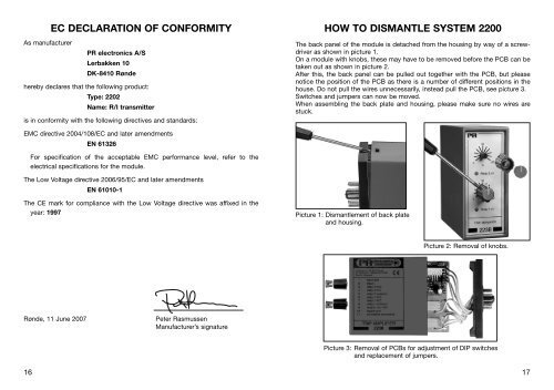
The back panel of the module is detached from the housing by way of a screwdriver<br />
as shown in picture 1.<br />
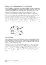
On a module with knobs, these may have to be removed before the PCB can be<br />
taken out as shown in picture 2.<br />
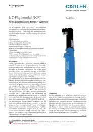
After this, the back panel can be pulled out together with the PCB, but please<br />
notice the position of the PCB as there is a number of different positions in the<br />
house. Do not pull the wires unnecessarily, instead pull the PCB, see picture 3.<br />
Switches and jumpers can now be moved.<br />
When assembling the back plate and housing, please make sure no wires are<br />
stuck.<br />
Picture 1: Dismantlement of back plate<br />
and housing.<br />
Picture 2: Removal of knobs.<br />
Picture 3: Removal of PCBs for adjustment of DIP switches<br />
and replacement of jumpers.<br />
17
![Bedienungsanleitung Typ BA_8627_8628_8632_DE [PDF, 459 KB]](https://img.yumpu.com/23348412/1/184x260/bedienungsanleitung-typ-ba-8627-8628-8632-de-pdf-459-kb.jpg?quality=85)
![Bedienungsanleitung_Typ BA_optris CT LT_DE [PDF, 4.00 MB]](https://img.yumpu.com/22293726/1/190x133/bedienungsanleitung-typ-ba-optris-ct-lt-de-pdf-400-mb.jpg?quality=85)
![Komplettes Datenblatt Typ 8821_DE [PDF, 499 KB] - MTS ...](https://img.yumpu.com/21876808/1/184x260/komplettes-datenblatt-typ-8821-de-pdf-499-kb-mts-.jpg?quality=85)
![Komplettes Datenblatt Typ 1440_DE [PDF, 524 KB] - MTS ...](https://img.yumpu.com/21876799/1/184x260/komplettes-datenblatt-typ-1440-de-pdf-524-kb-mts-.jpg?quality=85)


![Komplettes Datenblatt Typ 8411_DE [PDF, 459 KB] - MTS ...](https://img.yumpu.com/20642872/1/184x260/komplettes-datenblatt-typ-8411-de-pdf-459-kb-mts-.jpg?quality=85)

![Manual CT13 Serie [PDF, 1.00 MB] - MTS Messtechnik ...](https://img.yumpu.com/20620646/1/184x260/manual-ct13-serie-pdf-100-mb-mts-messtechnik-.jpg?quality=85)
![Komplettes Datenblatt Typ 4503A_DE [PDF, 795 KB] - MTS ...](https://img.yumpu.com/20620634/1/184x260/komplettes-datenblatt-typ-4503a-de-pdf-795-kb-mts-.jpg?quality=85)

![Prüfstandssysteme [PDF, 2.00 MB] - MTS Messtechnik Schaffhausen ...](https://img.yumpu.com/18883102/1/184x260/prufstandssysteme-pdf-200-mb-mts-messtechnik-schaffhausen-.jpg?quality=85)