
Create successful ePaper yourself
Turn your PDF publications into a flip-book with our unique Google optimized e-Paper software.
1. Verwendungszweck<br />
Offset-Parabolantenne<br />
für ein oder zwei Speisesysteme<br />
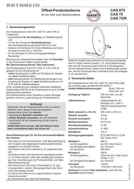
Die Parabolantenne <strong>CAS</strong> <strong>0<strong>75</strong></strong>, <strong>CAS</strong> <strong>75</strong>, <strong>CAS</strong> <strong>75</strong>/R ist<br />
vorgesehen:<br />
– ausschließlich für den Empfang von Satellitensignale<br />
und<br />
– nur für den Einsatz als Haushaltsantenne.<br />
Als Haushaltsantenne gilt gemäß DIN 4131 eine<br />
Antenne mit höchstens 6 m freier Mastlänge und einem<br />
Einspannmoment bis zu 1650 Nm.<br />
– für die Montage an nicht schwingungsanfälligen<br />
Bauwerken.<br />
Beachten Sie unbedingt die Angaben über die Grenzlast<br />
in den Technischen Daten (rechte Spalte).<br />
Bei Überschreitung können Teile losbrechen!<br />
Die Parabolantenne <strong>CAS</strong> <strong>0<strong>75</strong></strong>, <strong>CAS</strong> <strong>75</strong>, <strong>CAS</strong> <strong>75</strong>/R ist<br />
geeignet für die Verwendung mit<br />
- einem Speisesystem (LNB) zum Empfang der Signale<br />
von einer Satellitenposition<br />
- zwei Speisesystemen für Multifeedanwendungen zum<br />
Empfang der Signale von zwei Satellitenpositionen mit<br />
3°-4° oder 6° Satellitenabstand.<br />
Unter Verwendung der zusätzlich lieferbaren Multifeed-<br />
Adapterplatte ZAS 90 ist die Parabolantenne auch für drei<br />
Speisesysteme geeignet.<br />
Die Speisesysteme sowie Hinweise zu deren Montage<br />
gehören nicht zum Lieferumfang der Parabolantenne.<br />
Achtung!<br />
Verwenden Sie die Parabolantenne nicht zu anderen<br />
Zwecken, als in dieser Anleitung angegeben.<br />
Insbesondere dürfen Sie niemals<br />
• irgendwelche Bauteile verändern oder<br />
• andere Bauteile verwenden, als vom Hersteller<br />
ausdrücklich für die Verwendung mit der Antenne<br />
vorgesehen.<br />
Andernfalls kann es sein, daß die Antenne nicht<br />
mehr ausreichend stabil und sicher ist!<br />
Garantiebedingungen für die Korrosionsbeständigkeit<br />
der Antenne:<br />
- Die Antenne muss fachmännisch, unter Berücksichtigung<br />
der Vorgaben des beigelegten Anwendungshinweises,<br />
aufgebaut und montiert werden<br />
- Die Antenne darf nicht verändert (z. B. angebohrt) werden<br />
- Die Antenne darf nicht mechanisch beschädigt werden<br />
(z. B. Deformationen, tiefe oder großflächige Verletzungen<br />
bzw. Abschabungen der Pulverschichten und Oberflächenbeschichtung)<br />
- Die Antenne darf nicht durch Chemikalien (z. B. aus<br />
Lösungsmitteln, Lacken, Reinigungsmitteln oder Ähnlichem)<br />
beschädigt werden<br />
- Es darf an der Antenne nur original Kathrein-Zubehör<br />
verwendet werden<br />
- Als Garantienachweis dient der Kaufbeleg.<br />
2. Technische Daten<br />
<strong>CAS</strong> <strong>0<strong>75</strong></strong><br />
<strong>CAS</strong> <strong>75</strong><br />
<strong>CAS</strong> <strong>75</strong>/R<br />
Weiterhin besteht keine Garantie für Korrosionsbeständigkeit<br />
für Folgen höherer Gewalt, z. B. durch Blitzeinschlag<br />
oder bei der Verwendung der Antenne in Klimaregionen,<br />
die oft wiederkehrende, starke erosive Belastungen aufweisen,<br />
die die Schutzschichten innerhalb kurzer Zeit abtragen<br />
(z. B. Sandstürme).<br />
Die Parabolantenne <strong>CAS</strong> <strong>0<strong>75</strong></strong>, <strong>CAS</strong> <strong>75</strong>, <strong>CAS</strong> <strong>75</strong>/R erfüllt<br />
die Anforderungen gemäß DIN EN 50083-1.<br />
Größte Reflektorabmessungen: Breite: 766 mm<br />
Höhe: 831 mm<br />
Auslegung Tragarm: 790 mm max. von der<br />
Rohrmitte<br />
LNB-Aufnahme: Adapterplatte für die<br />
Montage von 1 oder 2<br />
Kathrein-Speisesystemen<br />
(LNB)<br />
Maße verpackt (L x B x H): 890 x 820 x 230 mm<br />
Gewicht verpackt: 9,0 kg<br />
Gewicht unverpackt: 8,2 kg<br />
Mastdurchmesser: 38-76 mm<br />
Elevationseinstellung: 5°-50°<br />
Azimuteinstellung: 0°-360°<br />
Windfläche: 0,5 m2 Schwingungsfestigkeit: ETS 300019-2-4 (12.94)<br />
IEC Class 4 M 5<br />
Windlast 1: 480 N<br />
bei Montagehöhe: bis 20 m über Grund<br />
bei Windgeschwindigkeit: bis 130 km/h<br />
bei Staudruck: 800 N/m2 Windlast 2: 658 N<br />
bei Montagehöhe: höher als 20 m über Grund<br />
(Faktor 1,37)<br />
bei Windgeschwindigkeit: bis 150 km/h<br />
Grenzlast 1044 N<br />
bei Staudruck: 1740 N/m2 (190 km/h)<br />
Achtung! Es können Teile losbrechen, wenn Sie die<br />
Grenzlast überschreiten!<br />
935.1524/F/1205/1.4d
3. Bevor Sie<br />
die Parabolantenne montieren, anschließen oder<br />
verwenden, beachten Sie unbedingt die Hinweise in<br />
dieser Anleitung! Wenn Sie die Hinweise nicht<br />
beachten,<br />
● können durch Fehler bei der Montage oder beim<br />
Anschluss Schäden an der Antenne oder am<br />
Montageort entstehen,<br />
● können durch Fehlverhalten Gefahren für Ihre<br />
Gesundheit und Ihr Leben entstehen,<br />
● haftet der Hersteller nicht für darauf zurückzuführende<br />
Fehlfunktionen und Schäden!<br />
Bitte beachten Sie bei Arbeiten an Antennenanlagen Ihre<br />
Verantwortung für Ihre Mitmenschen!<br />
Heben Sie die Anleitung für später auftretende Fragen<br />
auf und geben Sie diese bei einem Verkauf an den neuen<br />
Besitzer weiter!<br />
Vorsicht!<br />
Auf keinen Fall dürfen Sie unter Freileitungen<br />
Antennen montieren, andernfalls können vielleicht<br />
unbedingt erforderliche Mindestabstände<br />
unterschritten sein.<br />
Halten Sie auch zu den Seiten mindestens 1 m<br />
Abstand zu allen anderen elektrischen Einrichtungen<br />
ein!<br />
Es besteht Lebensgefahr, falls metallische<br />
Antennenteile elektrische Einrichtungen berühren!<br />
Montieren Sie niemals Antennen auf Gebäuden mit<br />
leicht entzündbaren Dachabdeckungen, z. B. Stroh,<br />
Reet oder ähnlichen Materialien!<br />
Andernfalls besteht Brandgefahr bei atmosphärischen<br />
Überspannungen (statische Aufladung) oder<br />
Blitzentladungen (z. B. Gewitter).<br />
4. Montageort wählen<br />
Der richtige Montageort ist entscheidend darüber, ob<br />
Ihre Parabolantenne sicher aufgebaut und optimal<br />
funktionieren kann.<br />
Bei der Montageortwahl sind bauwerkstypische<br />
Besonderheiten zu berücksichtigen. Bei Montage an<br />
Dach- und Gebäudekanten und zylindrischen Bauwerken<br />
ist gemäß DIN 1055, Teil 4 bzw. 4131 mit erhöhten Windoder<br />
Schwingungsbelastungen zu rechnen.<br />
Die dynamischen Eigenschaften der Antenne und des<br />
Bauwerks können sich gegenseitig beeinflussen und<br />
negativ verändern.<br />
Bei Nichtbeachtung kann eine Überschreitung der unter<br />
Punkt 2 genannten Grenzbelastung oder<br />
Schwingungsfestigkeit auftreten.<br />
Die Parabolantenne muss nicht unbedingt auf das Dach,<br />
weil es nicht auf die Höhe über Grund ankommt,<br />
sondern nur auf die freie „Sicht“ zum Satelliten. Deshalb<br />
kann ein geeigneter Montageort zum Beispiel auch im<br />
Garten, auf dem Balkon, auf der Terrasse, an einer<br />
Fassade oder an einer Garage zu finden sein.<br />
Wenn also möglich, sollten Sie besser nicht auf dem<br />
Dach montieren. Immerhin verringern Sie damit Ihren<br />
Arbeitsaufwand und die Gefahren bei Montagearbeiten<br />
auf dem Dach!<br />
� Für einen einwandfreien Empfang muß eine freie<br />
„Sicht“ in Richtung Süden (+/- 20°) gewährleistet<br />
sein, bei einer Erhebung von etwa 30°. Dann stehen<br />
Ihnen folgende Satelliten zur Auswahl:<br />
1 TÜRKSAT 1C 6 HOT BIRD 1–3<br />
2 ASTRA 2-Gruppe 7 EUTELSAT II F2<br />
3 ASTRA 3-Gruppe 8 TELECOM 2D<br />
4 ASTRA 1-Gruppe 9 HISPASAT 1A/1B<br />
5 EUTELSAT II F1<br />
● Achten Sie darauf, daß sich keine Hindernisse<br />
zwischen der Parabolantenne und dem jeweiligen<br />
Satelliten befinden (z. B. Bäume, Dach- oder<br />
Hausecken, andere Antennen).<br />
Diese können den Empfang sogar so beeinträchtigen,<br />
daß dieser bei ungünstiger Witterungslage völlig<br />
ausfällt.<br />
935.1524/F/1205/2.8d
Vorsicht!<br />
Bei der Montage der Parabolantenne können Gefahr<br />
für Ihr Leben und Ihre Gesundheit entstehen!<br />
Beachten Sie deshalb:<br />
� Die hier beschriebenen Montageschritte setzen gute<br />
handwerkliche Fähigkeiten und Kenntnisse vom<br />
Materialverhalten bei Windeinwirkung voraus.<br />
Lassen Sie die Arbeiten daher von einem Fachmann<br />
ausführen, wenn Sie nicht selbst über solche<br />
Voraussetzungen verfügen.<br />
� Betreten Sie Dächer oder absturzgefährdete<br />
Stellen nur mit einem ordnungsgemäß angelegten<br />
intakten Sicherheitsgurt!<br />
� Vergewissern Sie sich, ob das Dach Ihr Gewicht<br />
aushält. Betreten Sie niemals brüchige oder<br />
unstabile Flächen! Tragen Sie feste,<br />
rutschhemmende Schuhe!<br />
� Leitern oder andere Steighilfen müssen in einwandfreiem<br />
Zustand sein. Bauen Sie keine waghalsigen<br />
„Klettertürme“!<br />
� Wenn Passanten durch herabfallende Gegenstände<br />
während der Montage gefährdet werden können,<br />
müssen Sie den Gefahrenbereich absperren!<br />
� Achten Sie auf Freileitungen, falls solche in der<br />
Nähe des Montageortes vorbeiführen.<br />
Bei Berührung besteht akute Lebensgefahr!<br />
� Arbeiten Sie niemals bei aufziehendem Gewitter<br />
oder während eines Gewitters an Antennenanlagen.<br />
Es besteht Lebensgefahr!<br />
max. 4,0 m<br />
max. 3,3 m<br />
max. 2,5 m<br />
max. 1,3 m<br />
min. 0,7 m<br />
5. Antenne montieren<br />
Achten Sie bei der Montage des Antennenträgers (Mast<br />
oder Wandausleger) darauf, dass dieser senkrecht steht.<br />
Andernfalls kann die Ausrichtung der Antenne auf den<br />
Satelliten zu Schwierigkeiten führen.<br />
a) Anforderungen an den Antennenträger<br />
� Verwenden Sie nur Masten oder Tragrohre, die<br />
speziell für Antennenmontage geeignet sind.<br />
Andere Rohre oder Träger haben zumeist nicht die<br />
erforderliche Festigkeit bei Wind- und Wettereinflüssen.<br />
� Wählen Sie bei Mastmontage einen Rohrdurchmesser<br />
zwischen 48 bis 76 mm mit einer Wanddicke<br />
von mindestens 2 mm. Bei Wandmontage empfiehlt<br />
Kathrein die Verwendung der Wandhalterungen<br />
ZAS 60, ZAS 61, ZAS 74 oder ZAS 76.<br />
� Bei einer Mastmontage auf dem Dach, muss der Mast<br />
über mindestens 1/6 der freien Länge eingespannt<br />
werden (im Beispiel unten links sind dies 0,7 m).<br />
b) Mehrere Antennen an einem Antennenträger:<br />
� Montieren Sie die Parabolantenne am Mast ganz<br />
unten, um das Biegemoment an der Einspannstelle<br />
gering zu halten.<br />
� Überschreiten Sie keinesfalls die maximale<br />
Belastbarkeit für den Mast oder Masthalter, wie in<br />
deren technischen Daten angegeben.<br />
� Die maximale Belastbarkeit ist ausreichend<br />
berücksichtigt – wenn Sie Ihre Antennenanlage so<br />
ausführen, wie im Beispiel nebenan gezeichnet und<br />
übliche Haushaltsantennen sowie aus dem Fachhandel<br />
bezogene Mastbauteile (Rohr in Stahlgüte<br />
St 52 mit Außendurchmesser 60 mm und Wanddicke<br />
2,5 mm an der Masteinspannstelle – z. B. ZSH 59 von<br />
Kathrein) verwenden.<br />
Achtung! Bei einer anderen Bauweise müssen Sie<br />
Windlast und Biegemoment an der Einspannstelle<br />
gemäß DIN EN 50083-1 errechnen (oder von einem<br />
Fachmann errechnen lassen).<br />
935.1524/F/1205/3.8d
c) Tragarm und Reflektor montieren<br />
� Befestigen Sie den Tragarm am Antennenträger, wie<br />
aus der Zeichnung ersichtlich.<br />
� Ziehen Sie dabei die Flügelmuttern an der Mastschelle<br />
nur leicht an, bis der Tragarm für die weitere Montage<br />
am Mast sicher hält.<br />
� Hängen Sie dann den Reflektor in die vormontierten<br />
Befestigungsschrauben ein.<br />
� Ziehen Sie die Befestigungsschrauben erst nur leicht<br />
an – indem Sie diese, den Sechskantschlüssel erst am<br />
kurzen Ende haltend, handfest anziehen.<br />
� Drehen Sie nun den Sechskantschlüssel um. Wenn<br />
Sie mit dem langen Ende jetzt etwa 1/4 Umdrehung<br />
weiter anziehen, sind die Schrauben fest.<br />
Sollten Sie einen Drehmomentschlüssel zur<br />
Verfügung haben, ziehen Sie die Schrauben mit etwa<br />
4-5 Nm fest.<br />
935.1524/F/1205/4.8d
d) Speisesystem (LNB)<br />
Die Speisesysteme sowie Hinweise zu deren Montage gehören<br />
nicht zum Lieferumfang der Parabolantenne. Bitte<br />
entnehmen Sie daher die näheren Informationen zur sachgerechten<br />
Montage den Anleitungen, die dem jeweiligen<br />
Speisesystem beiliegen.<br />
� Über die Adapterplatte am Tragarm können Sie ein oder<br />
zwei Kathrein-Speisesysteme montieren. Auf der Adapterplatte<br />
zeigt die Markierung<br />
- 3 die Montageposition für ein einzelnes Speisesystem,<br />
- 2 und 4 die Montagepositionen für zwei Multifeed-Speisesysteme<br />
bei 3°-4° Satellitenabstand,<br />
- 1 und 5 die Montagepositionen für zwei Multifeed-Speisesysteme<br />
bei 6° Satellitenabstand.<br />
� Beispiel für Montagepositionen bei einer Mutifeedanwendung<br />
mit 3°-4° Satellitenabstand:<br />
Pos. 2 Pos. 4<br />
ASTRA 19,2° Ost EUTELSAT 16° Ost<br />
ASTRA 23,5° Ost ASTRA 19,2° Ost<br />
EUTELSAT 16° Ost EUTELSAT 13° Ost<br />
EUTELSAT 13° Ost EUTELSAT 10° Ost<br />
EUTELSAT 10° Ost EUTELSAT 7° Ost<br />
� Beispiel für Montagepositionen bei einer Multifeedanwendung<br />
mit 6° Satellitenabstand:<br />
Pos. 1 Pos. 5<br />
ASTRA 19,2° Ost EUTELSAT 13° Ost<br />
EUTELSAT 16° Ost EUTELSAT 10° Ost<br />
EUTELSAT 13° Ost EUTELSAT 7° Ost<br />
Tip: Bei Multifeedanwendungen sollte die Antenne auf den<br />
Satelliten ausgerichtet werden, der die pegelschwächeren<br />
Signale sendet.<br />
935.1524/F/1205/5.8d
6. Antenne ausrichten<br />
Die Antenne muss sowohl von der Richtung (Azimut), als<br />
auch von der Neigung (Elevation) her genau auf den<br />
Satelliten ausgerichtet sein. Bei Multifeedlösungen sollte<br />
die Antenne auf den Satelliten mit dem schwächsten<br />
Signalpegel ausgerichtet werden.<br />
a) Neigung (Elevation) einstellen<br />
� Lösen Sie die Schraube an der Neigungsskala<br />
(Elevation) links und rechts an der Halterung!<br />
� Achtung! Lösen Sie nicht die oberen Muttern an der<br />
Halterung – diese sind ab Werk mit einem festen<br />
Anzugsmoment eingestellt.<br />
� Stellen Sie dann die Neigung ein – den genauen<br />
Elevationswinkel für Ihren Standort finden Sie in der<br />
Anleitung für das Speisesystem. Wenn Sie über den<br />
Standort keine Angaben haben, können Sie die<br />
Neigung erst einmal auf etwa 30° einstellen.<br />
� Ziehen Sie erst nur eine der beiden Schrauben an der<br />
Neigungsskala wieder handfest an.<br />
b) Richtung (Azimut) einstellen<br />
Für die folgenden Schritte benötigen Sie gegebenenfalls<br />
einen Helfer, falls Sie nicht selbst an einem<br />
Antennenmessgerät oder Bildschirm mit angeschlossenem<br />
Satellitenreceiver das Ergebnis der<br />
Ausrichtarbeiten beobachten können.<br />
� Sellen Sie am Satellitenreceiver einen bekannten<br />
Programmplatz ein, um kontrollieren zu können, ob<br />
Sie auch wirklich den gewünschten Satelliten<br />
„getroffen“ haben.<br />
� Lösen Sie nun leicht die Flügelmuttern an der<br />
Mastschelle.<br />
� und drehen Sie die Antenne grob in Richtung Süden.<br />
Drehen Sie dann die Antenne langsam um die<br />
Mittelachse – nach links und rechts, bis das eingestellte<br />
Programm am besten zu empfangen ist.<br />
� Ziehen Sie dann die Flügelmuttern erst nur soweit<br />
fest, dass sich die Antenne nicht verdrehen kann.<br />
935.1524/F/1205/6.8d
c) Feineinstellung<br />
� Lösen Sie dann erneut die Schraube an der Neigungsskala<br />
und schwenken Sie die Antenne leicht nach oben<br />
und unten, bis Sie<br />
- entweder am Antennenmeßgerät das stärkste Antennensignal<br />
messen,<br />
- oder bei optischer Beurteilung am Bildschirm den besten<br />
Bildeindruck erzielen:<br />
Hierzu schwenken Sie die Antenne soweit nach oben und<br />
unten, bis Sie jeweils an die Grenze kommen, wo die ersten<br />
sogenannten „Fischchen“ (Analog) oder „Klötzchen“<br />
(Digital) am Bildschirm erscheinen. Stellen Sie die Antenne<br />
dann in die Mitte zwischen diesen beiden Grenzpunkten.<br />
• Korrigieren Sie nun abwechselnd die Richtung (Azimut)<br />
und Neigung (Elevation), bis sich das Mess- oder Bildergebnis<br />
nicht mehr verbessert.<br />
Hinweis: Beim Festdrehen der Muttern an der Mastschelle<br />
kann sich die Antenne leicht verdrehen! Dies sollten Sie bei<br />
der Feineinstellung beachten (und eventuell für eine ganz<br />
genaue Einstellung ausnutzen).<br />
d) Antenne endgültig festschrauben<br />
� Ziehen Sie anschließend die Muttern an der Mastschelle<br />
wechselseitig per Hand fest.<br />
Danach ziehen Sie die Flügelmuttern mit einem Gabelschlüssel<br />
(SW 13 mm) je eine Umdrehung nach.<br />
• Ziehen Sie danach links und rechts an der Halterung<br />
die Schraube an der Neigungsskala fest,<br />
� indem Sie diese mit dem Sechskantschlüssel erst mit<br />
dem kurzen Ende handfest anziehen<br />
� und dann am langen Ende 1/4 - 1/2 Umdrehung weiterdrehen<br />
(Drehmomentschlüssel: 5 - 10 Nm).<br />
• Kontrollieren Sie zum Schluß noch einmal alle Schraubverbindungen<br />
auf festen Sitz,<br />
• und befestigen Sie die Kabel mit Kabelbindern im gesamten<br />
Verlauf am Antennenträger, damit diese nicht<br />
durch Windbewegung scheuern und beschädigt werden.<br />
935.1524/F/1205/7.8d
Warnung!<br />
Erdungs- und Blitzschutzarbeiten dürfen wegen<br />
der Gefahr unzulänglicher Arbeitsergebnisse nur<br />
von hierfür speziell geschulten Fachkräften des<br />
Elektrohandwerks ausgeführt werden!<br />
� Führen Sie niemals Erdungs- und Blitzschutzarbeiten<br />
durch, wenn Sie nicht selbst Fachkraft mit<br />
entsprechenden Kenntnissen sind!<br />
Die hier abgedruckten Hinweise sind keine Aufforderung<br />
an Nichtfachleute, Erdungs- und<br />
Blitzschutzarbeiten in eigener Verantwortung durchzuführen,<br />
sondern dienen der von Ihnen beauftragten<br />
Fachkraft als zusätzliche Information!<br />
7. Antenne erden / Blitzschutz<br />
Die Antenne muss geerdet werden, so fordert es die<br />
DIN EN 50083-1. Hiervon ausgenommen sind nur solche<br />
Außenantennen,<br />
– die mehr als 2 m unterhalb der Dachkante<br />
– und zugleich weniger als 1,5 m von Gebäuden<br />
angebracht sind.<br />
Ungeachtet dessen, empfiehlt Kathrein generell aus<br />
Sicherheitsgründen einen Potentialausgleich<br />
vorzunehmen.<br />
Gefahren können nicht nur durch Gewitter entstehen<br />
(Blitzschlag), sondern auch durch statische Aufladung<br />
oder Kurzschluss in den angeschlossenen Geräten:<br />
� Deshalb müssen der Mast und die Außenleiter der<br />
Antennenkabel auf kürzestem Weg senkrecht über<br />
einen geeigneten Erdungsleiter mit der Blitzschutzanlage<br />
des Gebäudes verbunden sein (falls keine<br />
Blitzschutzanlage vorhanden ist: mit der Gebäudeerdung).<br />
a) Geeignet als Erdungsleiter<br />
– ist ein Einzelmassivdraht mit einem Querschnitt von<br />
min. 16 mm2 Kupfer, min. 25 mm2 Aluminium oder min.<br />
50 mm2 Stahl,<br />
– oder metallische Hausinstallationen (z. B. durchgehende<br />
Metallrohre der Wasser- oder Heizungsanlage),<br />
sofern diese vom Querschnitt und der<br />
Dauerhaftigkeit der elektrischen Verbindung her mindestens<br />
den Anforderungen an Erdungsleiter entsprechen.<br />
b) Nicht geeignet als Erdungsleiter<br />
– sind die Außenleiter der Antennenkabel<br />
– oder Schutzleiter oder Neutralleiter des<br />
Starkstromnetztes.<br />
Internet: http://www.kathrein.de<br />
Im schraffierten Bereich<br />
ist lt. Norm eine<br />
Antennenerdung nicht<br />
zwingend erforderlich.<br />
c) Führung von Erdungsleitern<br />
� Antennenkabel und Erdungsleiter dürfen nicht durch<br />
Räume geführt werden, die zur Lagerung von leicht<br />
entzündlichen Stoffen dienen (z. B. Heu, Stroh) oder<br />
in denen sich eine explosive Atmosphäre bilden kann<br />
(z. B. Gase, Dämpfe).<br />
� Bei Verwendung der Parabolantenne in kompletten<br />
Antennenanlagen (z. B. Verteilanlagen) müssen<br />
zudem die Erdungsmaßnahmen so ausgeführt sein,<br />
daß der Erdungsschutz auch dann bestehen bleibt,<br />
wenn einzelne Einheiten entfernt oder ausgetauscht<br />
werden.<br />
KATHREIN-Werke KG · Anton-Kathrein-Straße 1–3 · Postfach 10 04 44 · D-83004 Rosenheim · Deutschland · Telefon (0 80 31) 18 40 · Telefax (0 80 31) 18 43 06<br />
935.1524/F/1205/8.8d/SKS Technische Änderungen vorbehalten.
1. Intended use<br />
Offset parabolic antenna<br />
for one or two feed systems<br />
The parabolic antennas <strong>CAS</strong> <strong>0<strong>75</strong></strong>, <strong>CAS</strong> <strong>75</strong> and <strong>CAS</strong> <strong>75</strong>/R<br />
are exclusively destined for:<br />
– reception of satellite signals<br />
– utilisation as a domestic antenna. A domestic or<br />
private antenna is defined acc. to DIN 4131 as an<br />
antenna with a free mast length of 6 m and a bending<br />
moment at the fixing point of up to 1650 Nm.<br />
– installation on buildings not subject to oscillations<br />
It is important to observe the maximum load as<br />
mentioned in the technical data. If that value is<br />
exceeded, antenna parts can break loose.<br />
The parabolic antennas <strong>CAS</strong> <strong>0<strong>75</strong></strong>, <strong>CAS</strong> <strong>75</strong>, <strong>CAS</strong> <strong>75</strong>/R<br />
can be equipped with<br />
- one feed system (LNB) for reception of signals from<br />
satellites occupying the same orbital position<br />
- two feed systems for multifeed reception from satellites<br />
being 3°-4° or 6° apart<br />
With the aid of the additionally available multifeed<br />
adapter plate ZAS 90, three feed systems can be fixed<br />
on the parabolic antenna. Neither the feed systems nor<br />
the mounting instructions for the feed systems are in the<br />
scope of supply of the antenna.<br />
Attention!<br />
Do not use the parabolic antenna for purposes others<br />
than mentionned in these instructions.<br />
Never<br />
• modify any antenna parts or<br />
• use different components than those specifically<br />
recommended by the manufacturer for use with<br />
these antennas.<br />
As a result of that, the stability and security of the<br />
antenna can be effected.<br />
Warranty conditions regarding the corrosion resistance<br />
of the antenna:<br />
- The antenna must be set up and mounted in a workmanlike<br />
manner, in consideration of the enclosed instruction<br />
sheet<br />
- The antenna must not be changed in its design (e.g.<br />
drilled)<br />
- The antenna must not be spoiled mechanically (e.g. deformations,<br />
deep or extensive damage, or abrasion of the<br />
powder coating and surface coating)<br />
- The antenna must not be damaged due to exposure to<br />
chemicals (e.g. solvents, lacquers, detergents or similar)<br />
- Only accessories made by Kathrein may be used for the<br />
antenna<br />
- The sales slip serves as proof of warranty claims.<br />
Furthermore, the corrosion resistance for any damage<br />
resulting from force majeur, e.g. lightning strike, or if the<br />
antenna is used in regions which show frequently recurrent,<br />
erosive weather conditions wearing out the protective<br />
coating shortly (e.g. sandstorms) is not warranted for.<br />
2. Technical data<br />
<strong>CAS</strong> <strong>0<strong>75</strong></strong><br />
<strong>CAS</strong> <strong>75</strong><br />
<strong>CAS</strong> <strong>75</strong>/R<br />
The parabolic antennas <strong>CAS</strong> <strong>0<strong>75</strong></strong>, <strong>CAS</strong> <strong>75</strong>, <strong>CAS</strong> <strong>75</strong>/R<br />
comply with the specifications acc. to DIN EN 50083-1.<br />
Diameter of reflector: Width 766 mm<br />
Height 831 mm<br />
Length of the support arm: 790 mm max. from<br />
centre of mast<br />
LNB holder: Adapter plate for<br />
mounting 1 or 2 Kathrein<br />
feed systems (LNB)<br />
Measurements (packed): 890 x 820 x 230 mm<br />
Weight (packed): 9,0 kg<br />
Weight (unpacked): 8,2 kg<br />
Diameter of mast: 38 - 76 mm<br />
Elevation angle: 5°-50°<br />
Azimuth angle: 0°-360°<br />
Wind surface area: 0,5 m2 Vibration immunity: ETS 300019-2-4<br />
IEC Class 4 M 5<br />
Windload 1: 480 N<br />
for an installation height: up to 20 m above ground<br />
for a wind velocity: up to 130 km/h<br />
at a dynamic pressure: 800 N/m2 Windload 2: 658 N<br />
for an installation height: higher than 20 m above<br />
ground (factor 1.37)<br />
for a wind velocity: up to 150 km/h<br />
Maximum load: 1044 N<br />
with pressure head: 1740 N/m2 (190 km/h)<br />
Attention! If the max. load is exceeded, antenna parts<br />
can break loose<br />
935.1524/F/1205/1.8e
3. Before you<br />
begin to install, connect or utilize the antenna, observe<br />
the information you find in these mounting instructions. If<br />
you fail to pay attention to the information, one cannot<br />
exclude<br />
● that due to wrong installation and connecting, or<br />
because of having modified components or using<br />
other components, the antenna or the mounting place<br />
will be dammaged.<br />
● that because of inappropriate behaviour, risks for your<br />
and other people’s health and life will be created<br />
● that the manufacturer will decline the liability for faulty<br />
function and resulted dammages.<br />
It is most important that you are aware of the responsibility<br />
you have for your own and other people’s safety<br />
when working on the antenna system.<br />
Advice: Retain these instructions for possible later use<br />
when questions come up. In case you sell the antenna<br />
hand on the instructions to the new owner.<br />
Attention!<br />
Never install the antenna below overhead power lines.<br />
It can be that the required safety distance is not kept.<br />
Furthermore, make sure that the lateral distance to all<br />
other electrical systems is at least 1 m.<br />
Danger to life exists if you or the antenna make<br />
contact with live parts.<br />
Do not install the antenna on buildings with easily inflammable<br />
roofs (straw, reed or similar material). It<br />
exists fire hazard since the antenna is subject to static<br />
charge and lightning.<br />
South<br />
4. Mounting site<br />
The selection of the right mounting site for your antenna<br />
is important in order to ensure safe and satifactory<br />
operation. When choosing the mounting site, pay<br />
attention to typical characteristics of the building. If the<br />
antenna is installed on the edge of a roof or building, one<br />
must reckon acc. to DIN 1055, Part 4 or 4131 with a<br />
higher wind or oscillation load. This means that the<br />
dynamic characteristics of the antenna and the building<br />
can influence each other and change the characteristics<br />
negatively. Disregard of these circumstances can lead to<br />
exceeding the max. load or dynamic strength mentioned<br />
in sect. 2.<br />
It is not essential to mount the parabolic antenna on the<br />
roof since it is not height above ground that matters but<br />
an unimpeded line-of-sight to the satellite. Thus a<br />
suitable mounting location may be found in the garden,<br />
on the balcony/terrace or on a facade or garage, for<br />
example.<br />
Thus, if at all possible, the roof should be avoided as a<br />
mounting location. In any event this reduces the amount<br />
of work and avoids the dangers of doing installation<br />
work on the roof!<br />
� For good reception the antenna must have an unobstructed<br />
„visibility“ to the south (+/-20).<br />
The horizontal elevation angle must be 30°.<br />
The reception of the following satellites will then be<br />
possible:<br />
1 TÜRKSAT 1C 6 HOT BIRD 1–3<br />
2 ASTRA 2-Group 7 EUTELSAT II F2<br />
3 ASTRA 3-Group 8 TELECOM 2D<br />
4 ASTRA 1-Group 9 HISPASAT 1A/1B<br />
5 EUTELSAT II F1<br />
● Unobstructed „visibility“ means that there must be no<br />
obstacle (such as trees, buildings, roofs, balconies or<br />
similar obstacles) between the antenna and the satellite.<br />
Obstacles of this kind can impair the reception or<br />
even make reception impossible.<br />
935.1524/F/1205/2.8e
Attention!<br />
The installation work can create problems for your<br />
health and life.<br />
Therefore:<br />
� The mounting procedure described here demands<br />
skills and a knowledge how the antenna behaves<br />
when being subjected to atmospheric conditions. If<br />
you do not have the required skills, ask a specialist<br />
to do the installation work.<br />
� When working on the roof or near to drop away<br />
sites, use a safety belt.<br />
� Make sure that the roof will support your weight.<br />
Wear non-slip shoes.<br />
� Use ladders or other climbing aids that are in<br />
perfect condition.<br />
� If passers-by can be hurt by falling objects, block<br />
the danger area.<br />
� Watch out for overhead power lines. Getting into<br />
contact with these means danger to life!<br />
� Never work on antenna installations during a<br />
thunderstorm or when one is approaching.<br />
This can put your life at risk!<br />
FM<br />
UHF<br />
VHF<br />
5. Installation of the antenna<br />
Make sure that the mast is in a vertical position, otherwise<br />
the alignment of the antenna to the satellite can create<br />
problems.<br />
a) Requirements for the antenna support<br />
� Only use masts or supports specially suited to be<br />
used as antenna support. Other supports often do not<br />
have the necessary strength required for the environmental<br />
conditions.<br />
� Choose a mast that has a diameter of 48-76 mm and<br />
a wall thickness of a least 2 mm. For mounting on the<br />
wall, Kathrein recommands the wall supports ZAS 60,<br />
ZAS 61, ZAS 74 or ZAS 76.<br />
� When mounting takes place on the roof, see to it that<br />
at least one sixth of the total length of the mast is<br />
clamped (in the example below, one sixth equals 0.7<br />
m).<br />
b) Several antennas mounted on a mast:<br />
� We recommend to install the antenna on the lower<br />
part of the mast in order to keep the bending moment<br />
on the fixing point as low as possible.<br />
� Take care that you do not exceed the max. load rating<br />
for the mast or support given in the technical data.<br />
� If you use for your antenna system conventional<br />
household antennas and components bought from a<br />
specialist dealer (antenna mast with a steel quality<br />
ST 52, a diam. of 60 mm and a wall thickness in the<br />
fastening area of 2.5 mm – e. g. ZSH 59 from<br />
Kathrein) and effect the installation as shown in the<br />
example on the left, you can be sure that the max.<br />
load is sufficiently respected.<br />
Attention! In case your antenna array will be<br />
different, you must calculate the windload and<br />
bending moment acc. to DIN EN 50083-1 (or you ask<br />
a specialist to do it for you).<br />
935.1524/F/1205/3.8e
c) Mounting the support arm and the reflector<br />
� Mount the support arm on the mast as shown in the<br />
drawing<br />
� In doing so, tighten the wing-nuts on the mast clamp<br />
only slightly until the bracket holds securely for the<br />
further mounting on the mast.<br />
� Then lower the reflector into the pre-positioned<br />
securing screws.<br />
� Tighten the securing screws only slightly at first by<br />
holding the short end of the hexagon spanner until the<br />
screws are hand-tight.<br />
� Now turn the hexagon spanner around. If you now<br />
give the screws an extra one-quarter of a turn using<br />
the long end of the spanner they are fully tightened. If<br />
you should happen to have a torque wrench available,<br />
tighten the screws to about 4-5 Nm.<br />
Only tighten sightly<br />
First tighten slightly…<br />
…then effect 1/4 of a turn to<br />
screw down<br />
935.1524/F/1205/4.8e
d) Feed system (LNB)<br />
The feed system and the mounting instructions for the feed<br />
systems are not in the scope of the supply of the parabolic<br />
antenna. Detailed information for the correct installation is<br />
supplied together with each feed system.<br />
� The adapter plate on the support arm allows to mount<br />
one or two Kathrein feed systems. The marking on the<br />
adapter plate indicates<br />
- 3 as the mounting position for one feed system<br />
- 2 and 3 as the mounting positions for two multifeed<br />
systems allowing signal reception from satellites 3°-4°<br />
apart.<br />
- 1 and 5 as the mounting positions for two multifeed systems<br />
allowing signal reception from satellites 6° apart.<br />
� Example for mounting positions with multifeed reception<br />
from satellites 3°-4°:<br />
Pos. 2 Pos. 4<br />
ASTRA 19,2° East EUTELSAT 16° East<br />
ASTRA 23,5° East ASTRA 19,2° East<br />
EUTELSAT 16° East EUTELSAT 13° East<br />
EUTELSAT 13° East EUTELSAT 10° East<br />
EUTELSAT 10° East EUTELSAT 7° East<br />
� Example for mounting positions for multifeed reception<br />
from satellites 6° apart:<br />
Pos. 1 Pos. 5<br />
ASTRA 19,2° East EUTELSAT 13° East<br />
EUTELSAT 16° East EUTELSAT 10° East<br />
EUTELSAT 13° East EUTELSAT 7° East<br />
Tip! With multifeed applications the antenna should be aligned<br />
on the satellite with the weaker signal level.<br />
935.1524/F/1205/5.8e
6. Aligning the antenna<br />
With regard to the direction (Azimuth) and the inclination<br />
(Elevation), the antenna must be accurately aligned to<br />
the satellite. For multifeed reception it is necessary to<br />
align the antenna to the satelltie with the weaker signal<br />
level.<br />
a) Setting the inclination (Elevation)<br />
� Loosen the screws on the elevation scale – the one on<br />
the left as well as the one on the right of the mast<br />
bracket!<br />
� Attention! Do not loosen the nuts on the upper part of<br />
the mast bracket – these nuts have been tightened<br />
with a fixed torque in the factory.<br />
� Now set the elevation – You find the correct angle of<br />
the elevation in the mounting instructions supplied<br />
with the feed system. If you do not know the angle,<br />
first set the elevation initially to about 30°.<br />
� Hand-tighten just one of the two screws on the<br />
elevation scale.<br />
b) Setting the direction (Azimuth)<br />
For the following steps you need an assistant if you cannot<br />
operate an antenna measuring instrument nor watch<br />
on your television set which you have connected to a satellite<br />
receiver the result of your alignment work.<br />
� Select on your satellite receiver a programme well<br />
known in order to make sure you have aligned to the<br />
desired satellite.<br />
� Slacken the wing nuts on the mast bracket just<br />
slightly.<br />
� … and turn the antenna roughly towards the south.<br />
Then slowly turn the antenna around the mast axle –<br />
to the left and then to the right, until you obtain the<br />
best picture for the chosen programme.<br />
� Next tighten the wing nuts, but only to the extent that<br />
the antenna cannot turn.<br />
935.1524/F/1205/6.8e
c) Fine alignment<br />
� Loosen again the screw on the elevation scale and move<br />
the antenna slightly up and down until<br />
- the strongest signal is shown on the measuring instrument<br />
- or best picture quality is obtained on the TV set. To do<br />
this, swivel the antenna up and down until you reach<br />
the respective limits where the first „snow“ (analogue) or<br />
„blocks“ (digital) appear on the screen. The best picture<br />
quality will be found in the middle of these boundery positions.<br />
• Now alternately correct the direction (Azimuth) and the<br />
inclination (Elevation) until there is no more improvement<br />
of the measured value or the picture quality.<br />
Note: On tightening-up the nuts on the mast clamp, a slight<br />
movement of the antenna may occur! You need to take this<br />
into account during fine adjustment (and exploit it to get a<br />
very precise adjustment if need be).<br />
d) Final tightening up of antenna<br />
� Finally, hand-tighten the wing nuts on the mast clamp in<br />
alternation. Then tighten the wingnuts by 1 turn using an<br />
open-ended spanner (SW 13 mm).<br />
• Next tighten up the screws at left and right on the inclination<br />
scale support by<br />
• first hand-tightening using the shorter end of the hexagon<br />
spanner<br />
� then further tightening by 1/4 to 1/2 turn using the<br />
spanner‘s longer end.<br />
• Last of all, check again that all screw connections have<br />
been done properly<br />
• and secure the cable using cable ties along the full length<br />
of the antenna carrier so that it does not chafe and sustain<br />
damage due to wind effects.<br />
935.1524/F/1205/7.8e
Attention!<br />
Due to the danger of inadequate results from grounding<br />
and lightning conductor work, only electricians<br />
with the requisite specialised training must undertake<br />
this!<br />
� Never undertake grounding and ligthning conductor<br />
work yourself unless you are a specialist with the<br />
necessary know-how!<br />
The instructions supplied here are not an invitation to<br />
non-specialists to take responsibility for carrying out<br />
grounding and lightning conductor work themselves,<br />
but serve as additional information for the specialist<br />
engaged by them.<br />
7. Antenna grounding / Lightning protection<br />
The antenna must be grounded as is required by standard<br />
DIN EN 50083-1. The only external antennas exempted<br />
from this are those:<br />
– fitted more than 2 metres below the crest of the roof<br />
– whilst also less than 1.5 metres from the building.<br />
However, for safety reasons Kathrein recommends to<br />
mount a potential equalisation device.<br />
Danger can arise not just from thunderstorms (lightning<br />
strikes) but also through static charge accumulation or<br />
discharge in the devices attached:<br />
� Consequently, the mast and the external conductor of<br />
the antenna cable must be connected to the building’s<br />
lightning conductor system taking the shortest path<br />
vertically via a suitable grounding conductor (or to the<br />
building’s grounding system if no lightning conductor<br />
system is available).<br />
a) Suitable as grounding conductor:<br />
– a single solid wire with a min. cross-section of at least<br />
16 mm2 for copper, 25 mm2 for aluminium or 50 mm2 for<br />
steel<br />
– or metallic domestic installations (continuous metallic<br />
water or heating system pipes, for example) provided<br />
that they at least meet the requirements for grounding<br />
conductors in terms of cross-section and permanence<br />
of the electrical connection.<br />
b) Not suitable as grounding conductor:<br />
– the external conductors of the antenna cable<br />
– or the grounding conductor or neutral conductor of the<br />
power system<br />
Grounding<br />
conductor<br />
Grounding<br />
connection<br />
Equipotential<br />
bonding<br />
conductor<br />
Grounding the antenna<br />
installed in the hatched<br />
area is not explicitly<br />
required by standard.<br />
Equipotential bonding<br />
strip<br />
Mains<br />
connection<br />
230 V<br />
Equipotential<br />
bonding conductor<br />
Equipotential<br />
bonding strip<br />
c) Routing of grounding conductors<br />
� Antenna cables and grounding conductors must not<br />
be routed through rooms used for storing easily inflammable<br />
substances (hay or straw, for example) or in<br />
which an explosive atmosphere can develop (gases,<br />
vapours).<br />
� If the parabolic antenna is used in integrated antenna<br />
systems (e. g. distribution systems), the grounding<br />
measures must also be designed in such a way that<br />
grounding protection is still maintained if individual<br />
units are removed or replaced.<br />
KATHREIN-Werke KG · Anton-Kathrein-Straße 1–3 · Postfach 10 04 44 · D-83004 Rosenheim · Deutschland · Telefon (0 80 31) 18 40 · Telefax (0 80 31) 18 43 06<br />
935.1524/F/1205/8.8e/SKS Subject to technical changes.
1. Objectif<br />
Antenne parabolique offset<br />
pour une ou deux têtes SHF<br />
Les antennes paraboliques <strong>CAS</strong> <strong>0<strong>75</strong></strong>, <strong>CAS</strong> <strong>75</strong>, <strong>CAS</strong> <strong>75</strong>/R<br />
sont prêvues:<br />
– exclusivement pour la réception de signaux satellite et<br />
– uniquement en tant qu’antenne domestique.<br />
– Selon la norme DIN 4131, la longueur du mât d’une<br />
antenne domestique ne doit pas dépasser 6 m et son<br />
moment de fl exion être inférieur à 1650 Nm.<br />
– pour le montage sur des supports non susceptibles<br />
d’osciller.<br />
Tenez compte impérativement des indications relatives à<br />
la charge limite mentionnées dans les caractéristiques<br />
techniques (colonne de droite).<br />
En cas de dépassement, bris de pièces possible!<br />
Les antennes paraboliques <strong>CAS</strong> <strong>0<strong>75</strong></strong>, <strong>CAS</strong> <strong>75</strong>, <strong>CAS</strong> <strong>75</strong>/R<br />
permettent l’utilisation<br />
- d’une tête SHF (LNB) pour la réception des signaux<br />
d’une position de satellite ou<br />
- de deux têtes SHF pour une utilisation multi-satellite<br />
pour la réception des signaux de deux positions de<br />
satellite avec un écart entre les satellites de 3°-4°<br />
ou 6°. Grâce à l’emploi du support multi-têtes optionnel<br />
ZAS 90, l’antenne parabolique convient également pour<br />
trois têtes SHF.<br />
Les têtes SHF ainsi que leurs instructions de montage ne<br />
sont pas livrées avec l’antenne parabolique.<br />
Attention!<br />
N’employez pas l’antenne parabolique pour d’autres<br />
buts que ceux indiqués dans cette notice.<br />
En particulier, vous ne devez jamais<br />
• modifi er quelque pièce que ce soit ou<br />
• employer d’autres pièces que celles prévues par le<br />
fabricant.<br />
Dans le cas contraire, cela peut compromettre la<br />
stabilité et la sécurité de l’antenne!<br />
Conditions de garantie pour la résistance à la corrosion<br />
de l’antenne:<br />
- L’antenne doit être installée et montée par quelqu‘un de<br />
qualifi é en prenant en compte les indications de la notice<br />
d’utilisation jointe<br />
- L’antenne ne doit pas être modifi ée (par exemple par<br />
percement de trou)<br />
- L’antenne ne doit pas être endommagée mécaniquement<br />
(par exemple déformations, dommages profonds ou sur<br />
une large surface ou arrachement des couches pulvérisées<br />
et du revêtement de surface)<br />
- L’antenne ne doit pas être endommagée par des produits<br />
chimiques (par exemple des solvants, laques, produits de<br />
nettoyages ou autres)<br />
- On ne doit utiliser avec l’antenne que des accessoires<br />
d’origine Kathrein<br />
- La quittance sert de preuve de droit à la garantie<br />
En outre, la garantie de résistance à la corrosion ne<br />
<strong>CAS</strong> <strong>0<strong>75</strong></strong><br />
<strong>CAS</strong> <strong>75</strong><br />
<strong>CAS</strong> <strong>75</strong>/R<br />
s‘applique pas pour les conséquences de fortes puissances<br />
comme par exemple un éclair ou si l‘antenne est<br />
utilisée dans des régions climatiques qui sont soumises à<br />
des facteurs corrosifs puissants et réguliers, facteurs qui<br />
peuvent enlever les couches de protection au cours d‘une<br />
période réduite (par exemple des tempêtes de sable).<br />
2. Caractéristiques techniques<br />
Les antennes paraboliques <strong>CAS</strong> <strong>75</strong>, <strong>CAS</strong> <strong>75</strong>, <strong>CAS</strong> <strong>75</strong>/R<br />
satisfont aux exigences de la norme NF EN 50083-1.<br />
Diamètre du réfl ecteur: Largeur 766 mm<br />
Hauteur 831 mm<br />
Longueur du bras support: 790 mm max. du milieu<br />
du tube<br />
Support pour LNB: Support multi-têtes pour<br />
le montage de 1 ou 2<br />
têtes SHF Kathrein (LNB)<br />
Dimensions emballé (L x I x H): 890 x 820 x 230 mm<br />
Poids brut: 9,0 kg<br />
Poids net: 8,2 kg<br />
Diamètre du mât: 38-76 mm<br />
Réglage de l’élévation: 5°-50°<br />
Réglage de l’azimut: 0°-360°<br />
Surface au vent: 0,5 m 2<br />
Résistance aux oscillations: ETS 300019-2-4 (12.94)<br />
IEC Class 4 M 5<br />
Charge au vent 1: 480 N<br />
si montage en hauteur: jusqu’a 20 m au-dessus<br />
du sol<br />
avec vitesse du vent: jusqu’à 130 km/h<br />
avec pression dynamique: 800 N/m 2<br />
Charge au vent 2: 658 N<br />
si montage en hauteur: supérieur à 20 m audes-<br />
sus du sol (Faktor 1,37)<br />
avec vitesse du vent: jusqu’à 150 km/h<br />
Charge limite 1044 N<br />
avec pression dynamique: 1740 N/m 2 (190 km/h)<br />
Attention! Bris de pièces possible en cas de dépassment<br />
de la charge limite!<br />
935.1524/F/1205/1.8f
3. Conseils préliminaires<br />
Avant de monter, brancher ou employer l’antenne<br />
parabolique, observez obligatoirement les conseils de<br />
cette notice! Dans le cas contraire,<br />
● des erreurs de montage ou de branchement peuvent<br />
abîmer l’antenne ou endommager le lieu de montage,<br />
● votre santé ou votre vie peuvent être mises en danger<br />
suite à un comportement inadapté,<br />
● le fabricant n’assume aucune responsabilité pour<br />
les dégâts et dysfonctionnements en résultant.<br />
Lors de travaux sur des antennes, veuillez prendre en<br />
considération votre responsabilité envers toute autre<br />
personne.<br />
Conservez la notice pour pouvoir la consulter plus tard si<br />
nécessaire et, en cas de vente, remettez-la au nouveau<br />
propriétaire.<br />
Attention!<br />
Vous ne devez en aucun cas monter l’antenne en<br />
dessous de lignes électriques aériennes, sinon il se<br />
peut que les écarts obligatoirement nécessaires ne<br />
soient pas respectés.<br />
Maintenez également sur les côtés un écart d’au<br />
moins 1 m avec toutes les autres installations électriques!<br />
Danger de mort si des pièces métalliques de l’antenne<br />
touchent des installations électriques.<br />
Ne montez jamais l’antenne sur des bâtiments avec<br />
des couvertures de toit facilement inflammables,<br />
comme p. ex. paille, chaume ou autres matériaux<br />
semblables! Dans le cas contraire, il y a des risques<br />
en cas de surtensions atmosphériques (chargement<br />
d’électricité statique) ou de foudre (p. ex. orage).<br />
Sud<br />
4. Choix du lieu de montage<br />
Le lieu de montage correct est l’élément décisif pour une<br />
installation sûre et un fonctionnement optimale de<br />
l’antenne parabolique.<br />
Tenez compte des caractéristiques du support pour<br />
choisir le lieu de montage. En cas de montage sur les<br />
bords d’un toit ou d’un bâtiment et avec des supports<br />
cylindriques, il convient de tenir compte de charges<br />
élevées dues au vent ou à des oscillations conformément<br />
à la norme DIN 1055, partie 4 ou DIN 4131.<br />
Les caractéristiques dynamiques de l’antenne et du<br />
support peuvent s’influencer et interagir négativement.<br />
En cas de non-observation, il peut se produire un<br />
dépassement de la charge limite mentionnée au point 2<br />
ou de la résistance aux oscillations.<br />
L’antenne parabolique ne doit pas obligatoirement être<br />
montée sur le toit, car ce qui compte n’est pas la hauteur<br />
au-dessus du sol mais uniquement la „vue“ dégagée<br />
vers le satellite. C’est pourquoi un lieu de montage<br />
approprié peut se trouver également dans le jardin, sur le<br />
balcon, sur la terrasse, sur une façade ou sur le mur d’un<br />
garage.<br />
Si cela est possible, vous devriez au mieux éviter de<br />
monter sur le toit. Aprés tout, vous aurez moins de<br />
travail et moins de risques qu’avec une installation de<br />
l’antenne sur le toit!<br />
� Pour une réception parfaite, vous devez vous assurer<br />
d’avoir une „vue“ dégagée en direction du sud<br />
(+/-20°) avec une inclinaison d’environ +30°. Vous<br />
avez alors le choix parmi les satellites siuvants:<br />
1 TÜRKSAT 1C 6 HOT BIRD 1–3<br />
2 ASTRA 2-groupe 7 EUTELSAT II F2<br />
3 ASTRA 3-groupe 8 TELECOM 2D<br />
4 ASTRA 1-groupe 9 HISPASAT 1A/1B<br />
5 EUTELSAT II F1<br />
● Veillez à ce qu’il n’y ait pas d’obstacles entre l’antenne<br />
parabolique et le satellite voulu (p. ex. des arbres, un<br />
coin de toit ou de maison, d’autres antennes).<br />
Cela pourrait perturber la réception au point qu’en cas<br />
de conditions atmosphériques défavorables la<br />
réception ne soit plus du tout possible.<br />
935.1524/F/1205/2.8f
Attention!<br />
Lors du montage de l’antenne parabolique, votre santé<br />
et votre vie peuvent être mises en danger!<br />
C’est pourquoi observez ceci:<br />
� Les étapes de montage décrites ici présupposent de<br />
bonnes capacités de bricolage et la connaissance<br />
du comportement des matériaux sous l’influence du<br />
vent.<br />
� Demandez à un spécialiste de réaliser ces travaux si<br />
vous ne disposez pas vous-même de ces facultés.<br />
� Déplacez-vous sur les toits ou à des endroits avec<br />
des risques de chute uniquement après avoir mis une<br />
cinture de sécurité en bon état et conformément aux<br />
consignes.<br />
� Assurez-vous que le toit puisse supporter votre poids.<br />
Ne marchez jamais sur des surfaces fragiles ou<br />
instables! Portez des chaussures fermées et<br />
antidérapantes!<br />
� Les échelles ou moyens d’escalade doivent être en<br />
parfait état. Ne construisez pas d’échafaudage<br />
hasardeux!<br />
� Si des passants peuvent être mis en danger par des<br />
objets tombant du toit pendant le montage de l’antenne,<br />
vous devez interdire l’accès à la zone de danger!<br />
� Faites attention aux lignes électriques aériennes qui<br />
pourraient se trouver à proxinité du lieu de montage.<br />
Danger de mort imminent en cas de contact!<br />
� N’effectuez aucuns travaux sur une antenne en<br />
cas d’orage imminent ou pendant un orage.<br />
Danger de mort!<br />
FM<br />
UHF<br />
VHF<br />
5. Montage de l’antenne<br />
Faites attention lors du montage du support de l’antenne<br />
(mât ou embase murale) que ce dernier soit vertical, car<br />
dans le cas contraire cela peut entraîner des difficultés<br />
pour positionner l’antenne vers le satellite.<br />
a) Conditions requises pour le support de l’antenne<br />
� N’employez que des mâts ou tubes porteurs qui sont<br />
prévus spécialement pour le montage d’antenne. La<br />
plupart du temps, d’autres tubes ou supports n’ont<br />
pas la résistance exigée aux influences du vent et des<br />
intempéries.<br />
� Choisissez un diamètre de tube entre 48 et 76 mm<br />
avec une épaisseur de paroi d’au moins 2 mm. Pour<br />
le montage sur le mur, Kathrein recommande les<br />
supports mur ZAS 60, ZAS 61, ZAS 74 ou ZAS 76.<br />
� En cas de montage d’un mât sur un toit, le mât doit<br />
être fixé sur au moins 1/6 de la longueur libre (dans<br />
l’exemple ci-contre, il s’agit de 0,7 m).<br />
b) Plusieurs antennes sur un même support:<br />
� Montez l’antenne parabolique à la base du mât afin<br />
que le moment de flexion sur la partie fixe soit le plus<br />
faible possible.<br />
� Ne dépassez en aucun cas la limite de charge pour le<br />
mât ou son support comme cela est indique dans<br />
leurs caractéristiques techniques.<br />
� La charge limite maximale est suffisament respectée –<br />
si vous réalisez votre installation d’antnne comme<br />
cela est illustré dans l’exemple ci-contre et si vous<br />
utilisez des antennes domestiques usuelles ainsi que<br />
des pièces (mât d’antenne de qualité d’acier St 52, un<br />
diam. de 60 mm et un épaisseur de mur au point de<br />
fixation de 2,5 mm – p. ex. ZSH 59 de Kathrein)<br />
provenant du commerce spécialisé.<br />
Attention! En cas d’un autre type de construction,<br />
vous devez calculer (ou demander à un spécialiste de<br />
calculer) la charge au vent et le moment de flexion au<br />
point de fixation conformément à la norme NF EN<br />
50083-1.<br />
935.1524/F/1205/3.8f
c) Montage du bras et du réflecteur<br />
� Fixez le bras sur le support de l’antenne comme cela<br />
est montré sur le schéma ci-contre.<br />
� Ne serrez que légèrement les écrous à oreilles de la<br />
bride du mât jusqu’à ce que le bras soit suffisament<br />
immobilisé sur le mât pour pouvoir poursuivre le<br />
montage.<br />
� Accrochez ensuite le réflecteur aux vis de fixation<br />
prémontées.<br />
� Serrez les vis de fixation seulement légèrement – en<br />
tenant l’extrémité courte de la clé six pans jusqu’à ce<br />
que les vis ne puissent plus être desserrées à la main.<br />
� Utilisez maintenant l’éxtrémité longue de la clé pour<br />
serrer d’environ 1/4 de tour supplémentaire les vis qui<br />
sont alors immobilisées.<br />
Si vous disposez d’une clé dynamométrique, serrez<br />
les vis avec environ 4-5 Nm.<br />
Serrer légèrement!<br />
Serrer d’abord<br />
légèrement<br />
…ensuite serrer d’1/4 de tour<br />
supplémentaire<br />
935.1524/F/1205/4.8f
d) Tête SHF (LNB)<br />
Les têtes SHF ainsi que leurs instructions de montage ne<br />
sont pas livrées avec l‘antenne parabolique. Veuillez vous<br />
reporter aux notices livrées avec les LNB afin d‘y trouver les<br />
informations pour les monter correctement.<br />
� Vous avez la possibilité de monter un ou deux LNB de<br />
Kathrein sur le support multi-têtes en bout du bras. Le<br />
marquage sur ce support indique.<br />
- 3 la position de montage pour un LNB<br />
- 2 et 3 la position de montage pour deux LNB (multi-satellite)<br />
avec un écart entre satellites de 3°-4°<br />
- 1 et 5 la position de montage pour deux LNB (multi-satellite)<br />
avec un écart entre satellites de 6°<br />
� Exemple de positions de montage en cas d‘une application<br />
multi-satellites avec satellites séparés de 3°-4°.<br />
Pos. 2 Pos. 4<br />
ASTRA 19,2° Est EUTELSAT 16° Est<br />
ASTRA 23,5° Est ASTRA 19,2° Est<br />
EUTELSAT 16° Est EUTELSAT 13° Est<br />
EUTELSAT 13° Est EUTELSAT 10° Est<br />
EUTELSAT 10° Est EUTELSAT 7° Est<br />
� Exemple de positions de montage en cas d‘une application<br />
multi-satellites avec satellites séparés de 6°.<br />
Pos. 1 Pos. 5<br />
ASTRA 19,2° Est EUTELSAT 13° Est<br />
EUTELSAT 16° Est EUTELSAT 10° Est<br />
EUTELSAT 13° Est EUTELSAT 7° Est<br />
Conseil! En cas d‘applications multi-satellites, l‘antenne<br />
devrait être dirigée vers le satellite qui envoie les signaux<br />
les plus faibles.<br />
935.1524/F/1205/5.8f
6. Positionnement de l’antenne<br />
L’antenne doit être dirigée avec précision vers le satellite<br />
aussi bien en direction (azimut) qu’en inclinaison<br />
(élévation). En cas d’applications multi-satellites,<br />
l’antenne devrait être dirigée vers le satellite qui envoie<br />
les signaux les plus faibles.<br />
a) Réglage de l’inclinaison (élévation)<br />
� Desserrez la vis de l’échelle d’inclinaison (élévation)<br />
de chaque côté du support du bras!<br />
� Attention! Ne desserez pas les écrous en haut du<br />
support du bras – ils sont serrés en usine avec un<br />
couple de serrage précis.<br />
� Réglez ensuite l’inclinaison – vous trouvez l’angle<br />
précis d’élévation pour votre lieu d’installation dans la<br />
notice du LNB. Si vous n’avez pas d’indications sur le<br />
lieu d’installation, vous pouvez régler l’inclinaison dans<br />
un premier temps sur environ 30°.<br />
� Resserez ensuite une des deux vis de l’échelle<br />
d’inclinaison à la main.<br />
b) Réglage de la direction (azimut)<br />
Pour les étapes suivants, vous aurez besoin d’une<br />
personne pour vous aider si vous ne pouvez pas<br />
observer vous-même le résultat de vos opérations de<br />
positionnement sur un appareil de mesure d’antenne<br />
ou sur un écran branché sur un récepteur de satellite.<br />
� Choisissez sur le récepteur de satellite un numéro de<br />
programme connu afin de pouvoir contrôler si vous<br />
avez vraiment „ciblé“ le satellite voulu.<br />
� Desserez légèrement les écrous à oreilles sur la bride<br />
du mât<br />
� et tournez l’antenne approximativement en direction<br />
du sud. Tournez ensuite l’antenne lentement autour de<br />
l’axe central – vers la droite ou la gauche jusqu`à ce<br />
que la réception du programme choisi soit optimale.<br />
� Resserez ensuite les écrous à oreilles seulement jusqu’à<br />
ce l’antenne ne puisse plus tourner.<br />
935.1524/F/1205/6.8f
c) Réglage fin<br />
� Desserez ensuite de nouveau la vis de l‘échelle<br />
d‘inclinaison et incliner l‘antenne légèrement vers le bas<br />
ou le haut jusqu‘à ce que<br />
- vous mesuriez le signal d‘antenne le plus fort sur l‘appareil<br />
de mesure d‘antenne.<br />
- ou vous obteniez la meilleure image sur l‘écran d‘après<br />
votre appréciation visuelle: Pour ce faire, tournez<br />
l‘antenne vers le haut ou le bas jusqu‘à la limite où commence<br />
à apparaître la „neige“ (analogique) ou la „pixellisation<br />
(numérique). Placez alors l‘antenne au milieu de<br />
ces deux positions limites.<br />
• Corrigez maintenant alternativement la direction (azimut)<br />
et l‘inclinaison (élévation) jusqu‘à ce que le résultat<br />
mesuré ou vu ne puisse plus être emélioré.<br />
Remarque: Lors du serrage des écrous de la bride du mât,<br />
l‘antenne peut se tourner légèremnt! Vous devriez en tenir<br />
compte lors du réglage fin (et éventuellement en tirer partie<br />
pour obtenir un réglage très précis).<br />
d) Serrage définitif de l'antenne<br />
� Serrez ensuite à la main les écrous à oreilles de la bride<br />
du mât en passant de l‘un à l‘autre. Ensuite serrez les<br />
écrous à oreilles de 1 tour avec une clé plate (13 mm).<br />
• Serrez ensuite de chaque côté du support du bras les<br />
vis de l‘échelle d‘inclinaison<br />
� en les serrant d‘abord légèrement avec l‘extrémité<br />
courte de la clé six pans et ensuite avec l‘extrémité<br />
longue de la clé de 1/4 à 1/2 tour supplémentaire.<br />
� Contrôlez à la fin encore une fois que toutes les vis sont<br />
bien serrées<br />
• et immobilisez le câble avec des serre-câbles tout au<br />
long du support d‘antenne afin qu‘il ne s‘abîme pas suite<br />
à des frottements contre le support dus au vent.<br />
935.1524/F/1205/7.8f
Avertissement!<br />
Les travaux de mise à la terre et de protection<br />
parafoudre doivent être effectués uniquement par<br />
des électriciens spécialement formés dans ce but<br />
en raison du danger pouvant résulter de mesures<br />
insuffisantes!<br />
� N’effectuez jamais des travaux de mise à la terre ou<br />
de protection parafoudre si vous n’êtes pas<br />
vous-même un spécialiste ayant les connaissances<br />
nécessaires!<br />
Les remarques imprimées ici ne sont pas des incitations<br />
à des non-spécialistes d’effectuer des<br />
travaux de mise à la terre et de protection parafoudre<br />
de leur propre responsabilité, mais servent au<br />
contraire d’informations supplémentaires pour les<br />
spécialistes que vous avez mandatés!<br />
7. Mise à la terre de l’antenne/protection<br />
parafoudre<br />
La norme NF EN 50083-1 exige la mise à la terre de<br />
l’antenne à l’exception des antennes extérieures qui sont<br />
installées<br />
– à plus de 2 m en dessous du bord d’un toit<br />
– et en même temps à moins de 1,5 m de bâtiments.<br />
En dépit de cela et pour des raisons de sécurité, Kathrein<br />
recommande d’installer un dispositif d’égalisation<br />
du potentiel.<br />
Des dangers peuvent survenir non seulement à cause<br />
d’orages (foudre), mais aussi par chargement d’éléctricité<br />
statique ou suite à un court-circuit dans les appareils<br />
branchés à l’antenne.<br />
� Pour cette raison, le mât et le conducteur externe du<br />
câble d’antenne doivent être reliés au plus court<br />
verticalement à l’installation parafoudre du bâtiment<br />
via un câble de terre approprié (s’il n’y a pas de<br />
protection parafoudre, avec la terre du bâtiment).<br />
a) Câble de terre approprié<br />
Il s’agit<br />
– d’un fil massif monobrin avec une section minimale de<br />
16 mm2 pour un fil en cuivre, de 25 mm2 pour un fil en<br />
aluminium et de 50 mm2 pour un fil en acier,<br />
– ou d’une installation domestique métallique (p. ex.<br />
tuyau métallique pour l’eau ou le chauffage) à condition<br />
que leur section et leur durabilité au point de vue<br />
liaison électrique satisfassent aux exigences d’un<br />
conducteur de mise à la terre.<br />
b) Câbles de terre non approprié<br />
Il s’agit<br />
– des conducteurs externes du câble d’antenne<br />
– ou des conducteurs de protection ou neutres du<br />
réseau électrique à fort courant.<br />
ligne de<br />
terre<br />
prise de<br />
terre<br />
ligne de<br />
mise à la<br />
terre<br />
La norme n’exige pas<br />
qu’une antenne installée<br />
dans l’espace hachuré<br />
soit mise à la terre.<br />
rail de mise à la terre<br />
Prise secteur<br />
230 V<br />
ligne de mise<br />
à la terre<br />
rail de mise à la terre<br />
c) Passage des câbles de terre<br />
� Les câbles d’antenne et câbles de terre ne doivent<br />
pas traverser des locaux qui servent à entreposer des<br />
matériaux facilement inflammables (p. ex. foin, paille)<br />
ou dans lequels peut se former une atmosphère<br />
explosive (p. ex. gaz, vapeurs).<br />
� En cas d’utilisation de l’antenne parabolique dans des<br />
installations complètes d’antennes (p. ex. installations<br />
de distribution), les mesures de mise à la terre<br />
doivent en plus être exécutées de telle sorte que la<br />
protection de mise à la terre reste présente même en<br />
cas de retrait ou de remplacement de sous-ensembles<br />
de l’installation.<br />
KATHREIN-Werke KG · Anton-Kathrein-Straße 1–3 · Postfach 10 04 44 · D-83004 Rosenheim · Deutschland · Telefon (0 80 31) 18 40 · Telefax (0 80 31) 18 43 06<br />
935.1524/F/1205/8.8f/SKS Nous nous réservons le droit de toutes modifications techniques.
1. Scopo previsto<br />
Offset antenna parabolica<br />
per uno o due sistemi d‘alimentazione<br />
L‘antenna parabolica <strong>CAS</strong> <strong>0<strong>75</strong></strong>, <strong>CAS</strong> <strong>75</strong>, <strong>CAS</strong> <strong>75</strong>/R è prevista:<br />
– esclusivamente per la ricezione di segnali satellitari e<br />
– solo per l‘impiego come antenna domestica.<br />
Conformemente alla norma DIN 4131 come antenna<br />
domestica e da intendersi un‘antenna con massimo 6<br />
metri di lunghezza del traliccio e una coppia di serraggio<br />
massima di 1650 Nm.<br />
– per il montaggio su costruzioni resistenti alle vibrazioni.<br />
Si raccomanda di osservare assolutamente le specifiche<br />
inerenti al carico limite riportate nei dati tecnici (colonna<br />
destra).<br />
In caso di un superamento potrebbero spezzarsi dei<br />
componenti!<br />
L‘antenna parabolica <strong>CAS</strong> <strong>0<strong>75</strong></strong>, <strong>CAS</strong> <strong>75</strong>, <strong>CAS</strong> <strong>75</strong>/R è adatta<br />
per l‘impiego con<br />
- un sistema d‘alimentazione (LNB) per la ricezione dei<br />
segnali da una posizione satellitare<br />
- due sistemi d‘alimentazione per applicazioni Multifeed<br />
finalizzate alla ricezioine dei segnali di due posizioni<br />
satellitari ad una distanza dei satelliti di 3°-4° o 6°.<br />
Utilizzando la piastra di adattamento Multifeed ZAS 90<br />
disponibile in via supplementare l‘antenna parabolica può<br />
anche adattarsi per tre sistemi d‘alimentazione.<br />
I sistemi d‘alimentazione come pure le istruzioni per il<br />
montaggio degli stessi non sono compresi in dotazione con<br />
l‘antenna parabolica.<br />
Attenzione!<br />
Si raccomanda di non utilizzare l‘antenna parabolica per<br />
scopi diversi da quelli descritti nelle presenti istruzioni per<br />
l‘uso. In particolare si raccomanda di<br />
• non modificare mai alcuni componenti costruttivi<br />
oppure<br />
• utilizzare altri componenti costruttivi, se non quelli<br />
esclusivamente previsti per l‘utilizzo con l‘antenna.<br />
In caso contrario non sarebbe da escludere una insufficiente<br />
stabilità e sicurezza dell‘antenna!<br />
Condizioni di garanzia per la resistenza alla corrosione<br />
dell‘antenna:<br />
- L‘antenna deve essere montata in modo appropriato<br />
nella considerazione delle prescrizioni riportate nelle<br />
presenti istruzioni per l‘uso<br />
- Non è consentito apportare alcune modifiche all‘antenna<br />
(per esempio perforazioni)<br />
- Si raccomanda di evitare qualsiasi danneggiamento<br />
meccanico dell‘antenna (per esempio deformazione,<br />
danneggiamenti in profondità o in grande superficie ovvero<br />
graffi del rivestimento di polvere e del rivestimento<br />
superficiale)<br />
- L‘antenna non deve essere danneggiata da sostanze chimiche<br />
(per esempio solventi, vernici, detergenti o simili<br />
sostanze)<br />
- In combinazione con l‘antenna si possono utilizzare es<br />
<strong>CAS</strong> <strong>0<strong>75</strong></strong><br />
<strong>CAS</strong> <strong>75</strong><br />
<strong>CAS</strong> <strong>75</strong>/R<br />
clusivamente accessori originali della Kathrein<br />
- Come certificato di garanzia è richiesta la ricevuta<br />
d‘acquisto.<br />
La garanzia per la resistenza alla corrosione verrà declinata<br />
in seguito a forza maggiore, per esempio colpo di<br />
fulmine o nell‘utilizzo dell‘antenna in regioni climatiche<br />
che mostrano frequenti carichi erosivi periodici di notevole<br />
entità, che possono asportare entro breve tempo gli strati<br />
protettivi in superficie (per esempio tempesta di sabbia).<br />
2. Dati tecnici<br />
L‘antenna parabolica <strong>CAS</strong> <strong>0<strong>75</strong></strong>, <strong>CAS</strong> <strong>75</strong>, <strong>CAS</strong> <strong>75</strong>/R soddisfa<br />
i requisiti conformementa alla norma DIN EN 50083-1.<br />
Massime dimensioni del riflettore: Larghezza: 766 mm<br />
altezza: 831 mm<br />
Concezione del braccio portante: 790 mm max. dal<br />
centro del tubo<br />
Supporto LNB: Piastra d‘adattamento per<br />
il montaggio di 1 oppure 2<br />
sistemi d‘alimentazione<br />
Kathrein (LNB)<br />
Dimensioni con imballaggio (lun. x lar. x alt.):<br />
890 x 820 x 230 mm<br />
Peso con imballaggio: 9,0 kg<br />
Peso senza imballaggio: 8,2 kg<br />
Diametro del traliccio: 38-76 mm<br />
Regolazione dell‘elevazione: 5°-50°<br />
Regolazione dell‘Azimut: 0°-360°<br />
Superficie al vento: 0,5 m2 Resistenza contro vibrazioni: ETS 300019-2-4 (12.94)<br />
IEC Classe 4 M 5<br />
Carico al vento 1: 480 N<br />
all‘altezza di montaggio: fino a 20 m sopra suolo<br />
alla velocità del vento: fino a 130 km/h<br />
a pressione statica: 800 N/m2 Carico vento 2: 658 N<br />
all‘altezza di montaggio: oltre 20 m d‘altezza sopra<br />
suolo (fattore 1,37)<br />
alla velocità del vento: fino a 150 km/h<br />
Carico limite 1044 N<br />
a pressione statica: 1740 N/m2 (190 km/h)<br />
Attenzione! In caso di un superamento del carico limite<br />
potrebbero spezzarsi dei componenti!<br />
935.1524/F/1205/1.8i
3. Prima di<br />
montare, collegare oppure utilizzare l‘antenna parabolica,<br />
si raccomanda di osservare assolutamente le informazioni<br />
riportate nelle presenti istruzioni per l‘uso! In una<br />
mancata osservanza di queste informazioni,<br />
• a causa di probabili errori di montaggio o collegamento<br />
non saranno da escludere dei danni all‘antenna o al luo<br />
go di montaggio,<br />
• possono persistere imminenti pericoli per la salute o<br />
perfi no di morte in seguito a comportamenti erronei,<br />
• il costruttore non si assumerà alcuna responsabilità per<br />
errori di funzionamento o danni di conseguenza risultanti!<br />
Durante l‘esecuzione di lavori ad impianti di antenne si<br />
raccomanda di essere consapevoli del senso di responsabilità<br />
anche per le altre persone!<br />
Si raccomanda di conservare accuratamente le istrzioni per<br />
l‘uso per consultarle in un secondo momento nell‘ambito di<br />
eventuali questioni e di notarle anche al futuro proprietario<br />
in caso di una vendita!<br />
Prudenza!<br />
Non montare in nessun caso antenne sotto linee aeree,<br />
poiché la distanza di installazione potrebbe essere inferiore<br />
alle minime misure di sicurezza prescritte. Inoltre, è necessario<br />
rispettare anche una distanza laterale di almeno 1<br />
metro da tutti gli altri dispositivi elettrici!<br />
Persiste un‘imminente pericolo di morte nel caso in cui<br />
i componenti metallici dell‘antenna vengono in contatto<br />
con dei dispositivi elettrici!<br />
Non montare mai antenne sopra edifi ci con coperture di<br />
tetti facilmente infi ammabili, per esempio paglia, canna o<br />
simili materiali!<br />
In caso contrario persiste un‘imminente pericolo di incendio<br />
in caso di sovratensioni atmosferiche (cariche statiche) o<br />
colpi di fulmine (per esempio durante temporali).<br />
��<br />
Sud<br />
4. Scelta del luogo di montaggio<br />
Il corretto luogo di montaggio è determinante per garantire<br />
un funzionamento sicuro e ottimale delle antenne paraboliche.<br />
Nell‘ambito della scelta del luogo di montaggio sono da<br />
considerare le particolarità tipiche dell‘edifi cio. Per il montaggio<br />
sui bordi di tetti o di edifi ci e costruzioni cilindriche,<br />
conformemente alla norma DIN 1055, parte 4 risp. 4131,<br />
sono da considerare elevati carichi di vento e sollecitazioni<br />
di vibrazione. Le proprietà dinamiche dell‘antenna e della<br />
costruzione possono mostrare infl ussi reciproci e variare<br />
negativamente.<br />
In caso di una mancata osservanza, non è da escludere<br />
un superamento del carico limite menzionato al punto 2 o<br />
della resistenza alle vibrazioni. L‘antenna parabolica non<br />
deve essere installata assolutamente sopra il tetto, infatti,<br />
per la ricezione non è determinante l‘altezza sopra il suolo,<br />
bensì la „visuale“ libera verso il satellite. Pertanto, un luogo<br />
di montaggio adatto può essere, per esempio, anche in<br />
giardino, sul balcone, sul terrazzo, una facciata dell‘edifi cio<br />
oppure sopra un garage.<br />
Perciò, se possibile, si dovrebbe rinunciare<br />
all‘installazione sopra un tetto. Inoltre, in questo modo<br />
si riduce anche il dispendio di lavoro e si evita di incorrere<br />
a determinati rischi durante i lavori di montaggio sopra il<br />
tetto!<br />
� Per una ricezione perfetta è necessario che sia garantita<br />
una „visuale“ libera in direzione sud (+/- 20°), ad<br />
una elevazione di circa 30°. In tal modo si potranno<br />
scegliere i satelliti seguenti:<br />
1 TÜRKSAT 1C 6 HOT BIRD 1-3<br />
2 Gruppo ASTRA 2 7 EUTELSAT II F2<br />
3 Gruppo ASTRA 3 8 TELECOM 2D<br />
4 Gruppo ASTRA 1 9 HISPASAT 1A/1B<br />
5 EUTELSAT II F1<br />
• Si raccomanda di accertarsi che tra l‘antenna parabolica<br />
e il rispettivo satellite non si trovino alcuni ostacoli<br />
(per esempio alberi, angoli di tetti o caseggiati, altre<br />
antenne). Questi ostacoli possono pregiudicare la ricezione<br />
fi no ad un punto tale da impedire qualsiasi ricezione<br />
in condizioni atmosferiche sfavorevoli.<br />
935.1524/F/1205/2.8i
Prudenza!<br />
Durante il montaggio dell‘antenna parabolica possono persistere<br />
imminenti pericoli per la salute o perfi no di morte!<br />
Pertanto, si raccomanda di osservare quanto segue:<br />
• le operazioni di montaggio qui descritte premettono buone<br />
capacità artigianali come pure la conoscenza dei comportamenti<br />
dei materiali esposti al carico del vento. Per<br />
questo motivo si raccomanda di incaricare una persona<br />
specializzata all‘esecuzione di questi lavori, nel caso in<br />
cui non si fosse in possesso di tali requisiti.<br />
• si raccomanda di salire sui tetti o sui punti a rischio di<br />
caduta soltanto con una cintura di sicurezza correttamente<br />
applicata e intatta!<br />
• accertarsi che il tetto mostri una suffi ciente capacità per<br />
caricare il proprio peso. Non salire mai sopra superfi ci<br />
malferme o instabili! Portare delle scarpe robuste antiscivolo!<br />
• le scale o altri mezzi di salita devono trovarsi in uno stato<br />
perfetto e irreprensibile. Non costruire alcune „torri di salita“<br />
azzardate!<br />
• qualora dovessero essere messi in pericolo dei passanti<br />
da una eventuale caduta di oggetti durante le operazioni<br />
di montaggio, si raccomanda di interdire la zona di pericolo!<br />
• fare attenzione alle linee aeree, qualora dovessero passare<br />
in prossimità del luogo di montaggio. Persiste un imminente<br />
pericolo di morte acuto in seguito al contatto!<br />
• non lavorare mai all‘antenna durante l‘avvicinamento<br />
di un temporale. Persiste un imminente pericolo di<br />
morte!<br />
�<br />
5. Montaggio dell‘antenna<br />
Al montaggio del sostegno (traliccio oppure braccio a parete)<br />
dell‘antenna si raccomanda di accertarsi che si trovi in<br />
posizione perpendicolare. In caso contrario non sarebbero<br />
da escludere delle complicazioni al centraggio dell‘antenna<br />
sul satellite desiderato.<br />
�<br />
a) Requisiti al sostegno dell‘antenna<br />
• Utilizzare esclusivamente tralicci o tubi montanti specialmente<br />
concepiti per il montaggio di antenne. Altri tipi<br />
di tubi o sostegni maggiormente non mostrano la necessaria<br />
resistenza contro il carico al vento e gli infl ussi atmosferici.<br />
� Scegliere per il montaggio al traliccio un diametro del<br />
tubo tra 48 e 76 mm con uno spessore della parete di<br />
almeno 2 mm. Per il montaggio alla parete la<br />
Kathrein raccomanda l‘utilizzo dei sostegni da parete<br />
ZAS 60, ZAS 61, ZAS 74 o ZAS 76.<br />
� Qualora il traliccio venisse montato sul tetto, è necessario<br />
e questi venga serrato in almeno 1/6 della lunghezza<br />
libera (nell‘esempio in basso a sinistra sono<br />
0,7 m).<br />
b) Parecchie antenne in un solo sostegno:<br />
• Montare l‘antenna parabolica sul traliccio completamente<br />
in basso, affi nché il momento di torsione sul punto di serraggio<br />
sia il più basso possible.<br />
• Non superare in nessun caso la massima capacità di carico<br />
del traliccio o del sostegno dello stesso, come specifi<br />
cato nei dati tecnici.<br />
� Il massimo carico è suffi cientemente considerato,<br />
quando l‘impianto dell‘antenna viene eseguito come<br />
descritto all‘esempio riportato a fi anco e quando si utilizzano<br />
convenzionali antenne domestiche nonché<br />
componenti e tralicci disponibili nel commercio specialistico<br />
(tubi in qualità d‘acciaio ST 52 con diametro esterno<br />
60 mm e spessore della parete 2,5 mm nel punto<br />
di serraggio sul traliccio - per esempio ZSH 59 della<br />
Kathrein).<br />
Attenzione! In caso di un altro tipo di costruzione sarà<br />
necessario calcolare il carico al vento e il momento di<br />
torsione nel punto di serraggio secondo la norma DIN EN<br />
50083-1 (o lasciarlo calcolare da parte di una persona<br />
specializzata).<br />
935.1524/F/1205/3.8i
c) Montaggio del braccio portante e del rifl ettore<br />
� Fissare il braccio portante del sostegno dell‘antenna<br />
come mostrato nel disegno.<br />
• Stringere a tal fi ne i dadi a farfalla della fascetta del traliccio<br />
solo leggermente, affi nché il braccio portante si mantenga<br />
innanzitutto con sicurezza sul traliccio per l‘ulteriore<br />
montaggio.<br />
� Fissare successivamente il rifl ettore nelle viti di fi ssaggio<br />
premontate.<br />
� Stringere le viti di fi ssaggio innanzitutto solo leggermente<br />
- stringendo innanzitutto a mano servendosi della chiave<br />
esagonale solo dall‘estremità a corta.<br />
� Girare a questo punto la chiave esagonale. Le viti sono<br />
serrate, stringendo ulteriormente di un 1/4 di giro l‘estremità<br />
lunga. Qualora fosse disponibile una chiave dinamometrica,<br />
si raccomanda di serrare le viti con una<br />
coppia di serraggio di circa 4-5 Nm.<br />
�<br />
� �<br />
��<br />
935.1524/F/1205/4.8i
d) Sistema d‘alimentazione (LNB)<br />
I sistemi d‘alimentazione come pure le istruzioni per il montaggio<br />
degli stessi non sono compresi in dotazione con<br />
l‘antenna parabolica. Pertanto, si raccomanda di consultare<br />
le istruzioni per ottenere delle informazioni dettagliate<br />
riguardanti il montaggio appropriato del rispettivo sistema<br />
d‘alimentazione.<br />
� Attraverso la piastra di adattamento sul braccio portante<br />
si possono montare uno oppure due sistemi<br />
d‘alimentazione Kathrein. Sulla piastra di adattamento la<br />
marcatura<br />
- 3 indica la posizione di montaggio per un sistema<br />
d‘alimentazione,<br />
- 2 e 4 indicano la posizione di montaggio per due sistemi<br />
d‘alimentazione (Multifeed) ad una distanza dei satelliti<br />
di 3°-4°,<br />
- 1 e 5 indicano la posizione di montaggio per due sistemi<br />
d‘alimentazione (Multifeed) ad una distanza dei satelliti<br />
di 6°.<br />
� Esempio delle posizioni di montaggio per l‘applicazione<br />
Multifeed con una distanza dei satelliti di 3°-4°.<br />
Pos. 2 Pos. 4<br />
ASTRA 19,2° est EUTELSAT 16° est<br />
ASTRA 23,5° est ASTRA 19,2° est<br />
EUTELSAT 16° est EUTELSAT 13° est<br />
EUTELSAT 13° est EUTELSAT 10° est<br />
EUTELSAT 10° est EUTELSAT 7° est<br />
� Esempio delle posizioni di montaggio per l‘applicazione<br />
Multifeed con una distanza dei satelliti di 6°.<br />
Pos. 1 Pos. 5<br />
ASTRA 19,2° est EUTELSAT 13° est<br />
EUTELSAT 16° est EUTELSAT 10° est<br />
EUTELSAT 13° est EUTELSAT 7° est<br />
Suggerimento! Per le applicazioni Multifeed si dovrebbe<br />
centrare l‘antenna sul satellite che trasmette i segnali aventi<br />
il livello più debole.<br />
935.1524/F/1205/5.8i
6. Centraggio dell‘antenna<br />
L‘antenna deve essere esattamente centrata sul satellite<br />
sia in direzione (Azimut), che in inclinazione (elevazione).<br />
Nelle soluzioni Multifeed si dovrebbero centrare le antenne<br />
sul satellite che trasmette il segnale avente il livello più<br />
debole.<br />
a) Regolazione dell‘inclinazione (elevazione)<br />
� Allentare la vite nella scala di inclinazione (elevazione)<br />
a sinistra e a destra nel sostegno!<br />
� Attenzione! Non allentare i dadi superiori del<br />
sostegno - poiché sono regolati in fabbrica ad una coppia<br />
di serraggio fi ssa.<br />
• Regolare successivamente l‘inclinazione - l‘esatto angolo<br />
di elevazione della vostra posizione è da apprendere<br />
nelle istruzioni del sistema d‘alimentazione. Qualora non<br />
fossero disponibili alcune informazioni riguardanti la posizione,<br />
potete provare a regolare innanzitutto l‘inclinazione<br />
a circa 30°.<br />
� Stringere di nuovo soltanto una delle due viti nella scala<br />
di inclinazione.<br />
b) Regolazione della direzione (Azimut)<br />
Per le operazioni seguenti potrebbe essere eventualmente<br />
richiesto un aiutante, nel caso in cui non si potesse osservare<br />
in un misuratore di campo per antenne o sullo<br />
schermo il risultato del centraggio con il ricevitore satellitare<br />
collegato.<br />
• Regolare nel ricevitore satellitare un programma conos<br />
ciuto, per accertarsi di aver realmente „centrato“ il satellite<br />
desiderato.<br />
� Allentare a questo punto leggermente i dadi a farfalla<br />
nella fascetta del traliccio.<br />
• e girare l‘antenna approssimativamente in direzione sud.<br />
Girare quindi lentamente l‘antenna intorno all‘asse me<br />
diano in senso antiorario oppure orario, fi nché si riceve al<br />
meglio il programma regolato.<br />
• Successivamente occorre stringere i dadi a farfalla solo<br />
fi no ad un punto tale da non poter più girare l‘antenna.<br />
�<br />
��<br />
�<br />
935.1524/F/1205/6.8i
c) Aggiustamento fine<br />
� Allentare nuovamente la vite nella scala di inclinazione<br />
e orientare quindi l‘antenna leggermente verso l‘alto o<br />
verso il basso, finché<br />
- si può misurare o nel misuratore di campo dell‘antenna il<br />
segnale più intenso,<br />
- oppure, nell‘osservazione ottica sullo schermo, la miglio<br />
re immagine del programma. Orientare a tal fine<br />
l‘antenna verso l‘alto e il basso fino ad un punto tale da<br />
raggiungere rispettivamente il limite in cui appaiono i primi<br />
cosiddetti „pesciolini“ (in analogico) o „cubettini“ (in<br />
digitale) sullo schermo. Posizionare successivamente<br />
l‘antenna al centro tra questi due punti limite.<br />
• Correggere solo alternativamente la direzione (Azimut)<br />
e l‘inclinazione (elevazione), finché non migliora più ulteri<br />
ormente il risultato di misura o di immagine.<br />
Nota: Al serraggio dei dadi nella fascetta del traliccio potrebbe<br />
girarsi leggermente l‘antenna! Ciò dovrebbe essere<br />
osservato nell‘ambito dell‘aggiustamento fine (e da sfruttare<br />
eventualmente per una regolazione completamente esatta).<br />
d) Serraggio definitivo dell'antenna<br />
� Stringere successivamente i dadi a farfalla nella fascetta<br />
del traliccio alternativamente a mano. Dopodiché stingere<br />
i dadi a farfalla per mezzo di una chiave a forcella<br />
(misura 13 mm) rispettivamente di un giro.<br />
• Stringere quindi verso sinistra e destra nel sostegno la<br />
vite sulla scala di inclinazione,<br />
� stringendola innanzitutto a mano servendosi della chiave<br />
esagonale solo dall‘estremità corta<br />
� e stringendo indine ulteriormente dall‘estremità lunga<br />
di 1/4 - 1/1 giro (chiave dinamometrica 5 - 10 Nm).<br />
• Controllare infine ancora volta tutti collegamenti a vite,<br />
per accertarne la sede fissa,<br />
• e fissare quindi i cavi per mezzo delle fascette serracavo<br />
su tutto il tratto nel sostegno dell‘antenna, affinché<br />
non vengano graffiati o danneggiati a causa dei movimenti<br />
causati dal vento.<br />
935.1524/F/1205/7.8d
Avvertenza!<br />
I lavori di messa a terra e ai parafulmini devono essere<br />
eseguiti esclusivamente da parte di persone specializzate<br />
e appositamente addestrate in elettricità, a causa<br />
del rischio di insuffi cienti risultati di lavoro!<br />
• Non eseguire mai i lavori di messa a terra e ai parafulmini<br />
nel caso in cui non si fosse in possesso dei necessari<br />
requisiti elettrotecnici e delle rispettive nozioni!<br />
Le informazioni qui riportate non sono un invito rivolto<br />
a persone non specializzate ad eseguire lavori di messa<br />
a terra o ai parafulmini su propria responsabilità, bensì<br />
sono previste come informazioni supplementari per la persona<br />
specializzata incaricata!<br />
7. Messa a terra dell‘antenna / parafulmine<br />
L‘antenna deve essere collegata alla terra, come richiesto<br />
ai sensi della norma DIN EN 50083-1. Da qui sono escluse<br />
soltanto antenne esterne, che<br />
- sono montate ad una misura di oltre 2 metri al di sotto del<br />
bordo del tetto<br />
- e allo stesso tempo ad una misura inferiore di 1,5 m d<br />
l‘edifi cio.<br />
A prescindere da questa circostanza, per motivi di sicurezza,<br />
la Kathrein raccomanda di eseguire una compensazione<br />
del potenziale.<br />
I pericoli non possono derivare soltanto da temporali<br />
(colpo di fulmine), bensì anche a causa di cariche statiche<br />
oppure cortocircuito negli apparecchi collegati:<br />
• Pertanto, è necessario collegare sulla via più breve pos<br />
sibile il traliccio e i conduttori esterni per il collegamento<br />
dell‘antenna in perpendicolare attraverso un conduttore<br />
di terra adatto con un impianto di protezione contro colpi<br />
di fulmine installato nell‘edifi cio (qualora non fosse disponibile<br />
alcun impianto di protezione contro colpi di fulmine:<br />
con la messa a terra dell‘edifi cio).<br />
a) Conduttori di terra adatti<br />
- un cavo massiccio singolo avente una sezione di min. 16<br />
mm 2 di rame, min. 25 mm 2 d‘alluminio oppure min.<br />
50 mm 2 d‘acciaio,<br />
- o installazioni domestiche di metallo (per esempio tubi<br />
di metallo passanti dell‘impianto idrico e di riscaldamento),<br />
purché corrispondano alla sezione e alla resistenza<br />
continua del collegamento elettrico e almeno alle<br />
rivendicazioni del conduttore di terra.<br />
b) Conduttori di terra non adatti<br />
- sono i conduttori esterni per il collegamento dell‘antenna<br />
- oppure conduttori di protezione o conduttori neutri<br />
della rete d‘alta corrente.<br />
Internet: http://www.kathrein.de<br />
c) Posatura dei conduttori di terra<br />
• I cavi di collegamento dell‘antenna e i conduttori di terra<br />
non devono essere posati in locali adibiti allo stoccaggio<br />
di materiali facilmente infi ammabili (per esempio<br />
paglia, fi eno) o nei quali può formarsi un‘atmosfera esplosiva<br />
(per esempio gas oppure vapori).<br />
• Nell‘utilizzo dell‘antenna parabolica in impianti completi<br />
(per esempio in impianti di distribuzione) i collegamenti<br />
alla terra devono, inoltre, essere eseguiti in maniera tale<br />
da garantire una protezione di terra anche nel caso in<br />
cui venissero sconnesse oppure sostituite delle singole<br />
unità.<br />
KATHREIN-Werke KG • Anton-Kathrein-Straße 1 - 3 • Postfach 10 04 44 • D-83004 Rosenheim • Germania • Telefono (0 80 31) 1 84-0 • Fax (0 80 31) 1 84-3 06<br />
935.1524/F/1205/8.8i Modifi che tecniche riservate!