poly-v pulleys poulies poly-v poly-v scheiben poleas ... - SIT (Schweiz)
poly-v pulleys poulies poly-v poly-v scheiben poleas ... - SIT (Schweiz)
poly-v pulleys poulies poly-v poly-v scheiben poleas ... - SIT (Schweiz)

You also want an ePaper? Increase the reach of your titles
YUMPU automatically turns print PDFs into web optimized ePapers that Google loves.
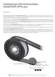
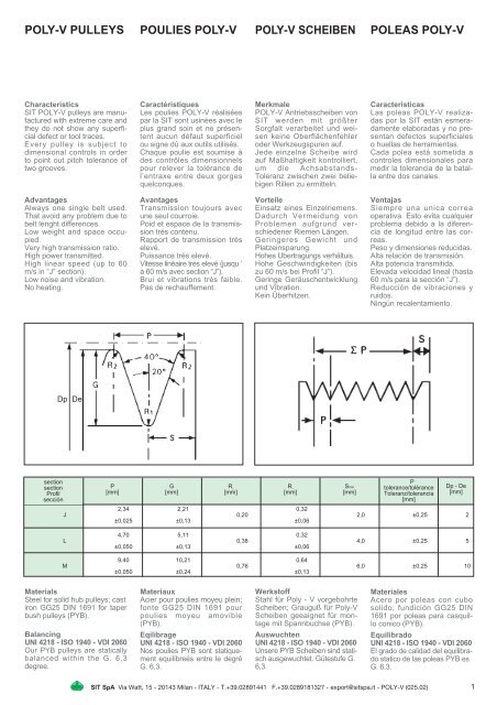
POLY-V PULLEYS POULIES POLY-V POLY-V SCHEIBEN POLEAS POLY-V<br />
Characteristics<br />
<strong>SIT</strong> POLY-V <strong>pulleys</strong> are manufactured<br />
with extreme care and<br />
they do not show any superficial<br />
defect or tool traces.<br />
Every pulley is subject to<br />
dimensional controls in order<br />
to point out pitch tolerance of<br />
two grooves.<br />
Advantages<br />
Always one single belt used.<br />
That avoid any problem due to<br />
belt lenght differences.<br />
Low weight and space occupied.<br />
Very high transmission ratio.<br />
High power transmitted.<br />
High linear speed (up to 60<br />
m/s in “J” section).<br />
Low noise and vibration.<br />
No heating.<br />
section<br />
section<br />
Profil<br />
sección<br />
Dp De<br />
Caractéristiques<br />
Les <strong>poulies</strong> POLY-V réalisées<br />
par la <strong>SIT</strong> sont usinées avec le<br />
plus grand soin et ne présentent<br />
aucun défaut superficiel<br />
ou signe dû aux outils utilisés.<br />
Chaque poulie est soumise à<br />
des contrôles dimensionnels<br />
pour relever la tolérance de<br />
l’entraxe entre deux gorges<br />
quelconques.<br />
Avantages<br />
Transmission toujours avec<br />
une seul courroie.<br />
Poid et espace de la transmission<br />
trés contenu.<br />
Rapport de transmission trés<br />
elevé.<br />
Puissance trés elevé.<br />
Vitesse linèaire trés elevé (jusqu ‘<br />
à 60 m/s avec section “J”).<br />
Brui et vibrations trés faible.<br />
Pas de rechauffement.<br />
Merkmale<br />
POLY-V Antriebs<strong>scheiben</strong> von<br />
<strong>SIT</strong> werden mit größter<br />
Sorgfalt verarbeitet und weisen<br />
keine Oberflächenfehler<br />
oder Werkzeugspuren auf.<br />
Jede einzelne Scheibe wird<br />
auf Maßhaltigkeit kontrolliert,<br />
um die Achsabstands-<br />
Toleranz zwischen zwei beliebigen<br />
Rillen zu ermitteln.<br />
Vorteile<br />
Einsatz eines Einzelriemens.<br />
Dadurch Vermeidung von<br />
Problemen aufgrund verschiedener<br />
Riemen Längen.<br />
Geringeres Gewicht und<br />
Platzeinsparung.<br />
Hohes Ubertragungs verhältuis.<br />
Hohe Geschwindigkeiten (bis<br />
zu 60 m/s bei Profil “J”).<br />
Geringe Geräuschentwicklung<br />
und Vibration.<br />
Kein Überhitzen.<br />
P G R 2 R 1 Smin<br />
[mm] [mm] [mm] [mm] [mm]<br />
Caracteristicas<br />
Las <strong>poleas</strong> POLY-V realizadas<br />
por la <strong>SIT</strong> estàn esmeradamente<br />
elaboradas y no presentan<br />
defectos superficiales<br />
o huellas de herramientas.<br />
Cada polea está sometida a<br />
controles dimensionales para<br />
medir la tolerancia de la batalla<br />
entre dos canales.<br />
Ventajas<br />
Siempre una unica correa<br />
operativa. Esto evita cualquier<br />
problema debido a la diferencia<br />
de longitud entre las correas.<br />
Peso y dimensiones reducidas.<br />
Alta relación de transmisión.<br />
Alta potencia transmitida.<br />
Elevada velocidad lineal (hasta<br />
60 m/s para la sección “J”).<br />
Reducción de vibraciones y<br />
ruidos.<br />
Ningún recalentamiento.<br />
P<br />
tolerance/tolérance<br />
Toleranz/tolerancia<br />
[mm]<br />
2,34 2,21 0,32<br />
J 0,20 2,0 ±0,25 2<br />
±0,025 ±0,13 ±0,06<br />
4,70 5,11 0,32<br />
L 0,38 4,0 ±0,25 5<br />
±0,050 ±0,13 ±0,06<br />
9,40 10,21 0,64<br />
M 0,76 6,0 ±0,25 10<br />
±0,050 ±0,24 ±0,13<br />
Materials<br />
Steel for solid hub <strong>pulleys</strong>; cast<br />
iron GG25 DIN 1691 for taper<br />
bush <strong>pulleys</strong> (PYB).<br />
Balancing<br />
UNI 4218 - ISO 1940 - VDI 2060<br />
Our PYB <strong>pulleys</strong> are statically<br />
balanced within the G. 6,3<br />
degree.<br />
Materiaux<br />
Acier pour <strong>poulies</strong> moyeu plein;<br />
fonte GG25 DIN 1691 pour<br />
<strong>poulies</strong> moyeu amovible<br />
(PYB).<br />
Eqilibrage<br />
UNI 4218 - ISO 1940 - VDI 2060<br />
Nos <strong>poulies</strong> PYB sont statiquement<br />
equilíbreés entre le degré<br />
G. 6,3.<br />
Werkstoff<br />
Stahl für Poly - V vorgebohrte<br />
Scheiben; Grauguß für Poly-V<br />
Scheiben geeaignet für montage<br />
mit Spannbuchse (PYB).<br />
Auswuchten<br />
UNI 4218 - ISO 1940 - VDI 2060<br />
Unsere PYB Scheiben sind statisch<br />
ausgewuchtet. Gütestufe G.<br />
6,3.<br />
Materiales<br />
Acero por <strong>poleas</strong> con cubo<br />
solido; fundición GG25 DIN<br />
1691 por <strong>poleas</strong> para casquillo<br />
conico (PYB).<br />
Equilibrado<br />
UNI 4218 - ISO 1940 - VDI 2060<br />
El grado de calidad del equilibrado<br />
statico de las <strong>poleas</strong> PYB es<br />
G. 6,3.<br />
<strong>SIT</strong> SpA Via Watt, 15 - 20143 Milan - ITALY - T.+39.02891441 F.+39.0289181327 - export@sitspa.it - POLY-V (025.02)<br />
Dp - De<br />
[mm]<br />
1
DIMENSIONS DIMENSIONS ABMESSUNGEN DIMENSIONES<br />
SECTION J SECTION J PROFIL J SECCIÓN J<br />
De Groove<br />
[mm] number<br />
Taper<br />
Bush<br />
Type<br />
Fig.<br />
L Z M U d<br />
[mm] [mm] [mm] [mm] [mm]<br />
20 4 – 1 22,5 – – – 15<br />
8 – 1 32 – – – 15<br />
12 – 1 41,5 – – – 15<br />
16 – 1 51 – – – 15<br />
20 – 1 61 – – – 15<br />
25 4 – 1 22,5 – – – 15<br />
8 – 1 32 – – – 15<br />
12 – 1 41,5 – – – 15<br />
16 – 1 51 – – – 15<br />
20 – 1 61 – – – 15<br />
30 4 – 1 22,5 – – – 19,5<br />
8 – 1 32 – – – 19,5<br />
12 – 1 41,5 – – – 19,5<br />
16 – 1 51 – – – 19,5<br />
20 – 1 61 – – – 19,5<br />
35 4 – 1 22,5 – – – 19,5<br />
8 – 1 32 – – – 19,5<br />
12 – 1 41,5 – – – 19,5<br />
16 – 1 51 – – – 19,5<br />
20 – 1 61 – – – 19,5<br />
40 4 – 1 22,5 – – – 12<br />
8 – 1 32 – – – 12<br />
12 – 1 41,5 – – – 12<br />
16 – 1 51 – – – 12<br />
20 – 1 61 – – – 12<br />
45 4 – 1 22,5 – – – 12<br />
8 – 1 32 – – – 12<br />
12 – 1 41,5 – – – 12<br />
16 – 1 51 – – – 12<br />
20 – 1 61 – – – 12<br />
50 4 – 1 22,5 – – – 12<br />
8 – 1 32 – – – 12<br />
12 – 1 41,5 – – – 12<br />
16 – 1 51 – – – 12<br />
20 – 1 61 – – – 12<br />
56 4 1108 7 23 9,5 50 – –<br />
8 1108 3 23 – – – –<br />
12 – 1 41,5 – – – 12<br />
16 – 1 51 – – – 12<br />
20 – 1 61 – – – 12<br />
60 4 1108 7 23 9,5 50 – –<br />
8 1108 3 23 – – – –<br />
12 1108 2 23 9,5 – 45 –<br />
16 – 1 51 – – – 12<br />
20 – 1 61 – – – 12<br />
63 4 1108 7 23 9,5 50 – –<br />
8 1108 3 23 – – – –<br />
12 1108 2 23 9,5 – 45 –<br />
16 – 1 51 – – – 12<br />
20 – 1 61 – – – 12<br />
67 4 1108 7 23 9,5 50 – –<br />
8 1108 3 23 – – – –<br />
12 1108 2 23 9,5 – 51 –<br />
16 – 1 51 – – – 12<br />
20 – 1 61 – – – 12<br />
De Groove<br />
[mm] number<br />
Taper<br />
Bush Fig.<br />
L Z M U<br />
Type [mm] [mm] [mm] [mm]<br />
71 4 1108 7 23 19,5 60 –<br />
8 1108 3 23 – – –<br />
12 1108 2 23 19,5 – 55<br />
16 1215 3 42 – – 55<br />
20 1215 2 42 10 – 55<br />
75 4 1108 7 23 19,5 60 –<br />
8 1108 3 23 – – –<br />
12 1210 2 26 16,5 – 59<br />
16 1610 2 26 16 – 59<br />
20 1615 2 42 10 – 59<br />
80 4 1310 7 26 12,5 70 –<br />
8 1310 7 26 13 70 –<br />
12 1610 2 26 16,5 – 64<br />
16 1610 2 26 16 – 64<br />
20 1615 2 42 10 – 64<br />
85 4 1310 7 26 12,5 70 –<br />
8 1310 7 26 13 70 –<br />
12 1610 2 26 16,5 – 69<br />
16 1610 2 26 16 – 69<br />
20 1615 2 42 10 – 69<br />
90 4 1610 7 26 12,5 82 –<br />
8 1610 7 26 13 82 –<br />
12 1610 2 26 16,5 – 74<br />
16 1610 2 26 16 – 74<br />
20 1615 2 42 10 – 74<br />
95 4 1610 7 26 12,5 82 –<br />
8 1610 7 26 13 82 –<br />
12 1610 2 26 16,5 – 79<br />
16 1610 2 26 16 – 79<br />
20 1615 2 42 10 – 79<br />
100 4 1610 7 26 12,5 82 –<br />
8 1610 7 26 13 82 –<br />
12 1610 2 26 16,5 – 82<br />
16 1610 2 26 16 – 82<br />
20 1615 2 42 10 – 82<br />
106 4 1610 7 26 12,5 88 –<br />
8 1610 7 26 13 88 –<br />
12 1610 2 26 16,5 – 88<br />
16 1610 2 26 16 – 88<br />
20 1615 2 42 10 – 88<br />
112 4 1610 7 26 12,5 90 –<br />
8 1610 7 26 13 90 –<br />
12 1610 2 26 16,5 – 94<br />
16 1610 2 26 16 – 94<br />
20 1615 2 42 10 – 94<br />
118 4 1610 7 26 12,5 90 –<br />
8 1610 7 26 13 90 –<br />
12 2012 2 32 10,5 – 98<br />
16 2012 2 32 10 – 98<br />
20 2012 2 32 20 – 98<br />
125 4 1610 8 26 12,5 90 109<br />
8 1610 8 26 13 90 109<br />
12 2012 2 32 10,5 – 105<br />
16 2012 2 32 10 – 105<br />
20 2517 2 45 17 – 105<br />
De Groove<br />
[mm] number<br />
132 4 1610 8 26 12,5 90 116<br />
8 1610 8 26 13 90 116<br />
12 2012 2 32 10,5 – 112<br />
16 2012 2 32 10 – 112<br />
20 2517 2 45 17 – 112<br />
140 4 1610 8 26 12,5 90 124<br />
8 1610 8 26 13 90 124<br />
12 2517 7 45 12,5 120 –<br />
16 2517 7 45 13 120 –<br />
20 2517 2 45 17 – 124<br />
160 4 2012 8 32 18,5 110 144<br />
8 2012 8 32 19 110 144<br />
12 2517 8 45 12,5 120 140<br />
16 2517 8 45 13 120 140<br />
20 2517 2 45 17 – 140<br />
180 4 2012 6 32 19,25 110 164<br />
8 2012 6 32 14,5 110 164<br />
12 2517 6 45 16,25 120 160<br />
16 2517 6 45 11,5 120 160<br />
20 2517 5 45 13,5 120 160<br />
200 4 2012 6 32 19,25 110 185<br />
8 2012 6 32 14,5 110 185<br />
12 2517 6 45 16,25 120 180<br />
16 2517 6 45 11,5 120 180<br />
20 2517 5 45 13,5 120 180<br />
224 4 2012 6 32 19,25 110 208<br />
8 2012 6 32 14,5 110 208<br />
12 2517 6 45 16,25 120 204<br />
16 2517 6 45 11,5 120 204<br />
20 2517 5 45 13,5 120 204<br />
250 4 2012 9 32 19,25 110 234<br />
8 2012 9 32 14,5 110 234<br />
12 2517 6 45 16,25 120 230<br />
16 2517 6 45 11,5 120 230<br />
20 2517 5 45 13,5 120 230<br />
280 4 2012 9 32 19,25 110 264<br />
8 2012 9 32 14,5 110 264<br />
12 2517 9 45 16,25 120 260<br />
16 2517 9 45 11,5 120 260<br />
20 2517 10 45 13,5 120 260<br />
315 4 2012 9 32 19,25 110 299<br />
8 2012 9 32 14,5 110 299<br />
12 2517 9 45 16,25 120 295<br />
16 2517 9 45 11,5 120 295<br />
20 2517 10 45 13,5 120 295<br />
355 4 2517 9 45 15,7 120 339<br />
8 2517 9 45 11 120 339<br />
12 2517 9 45 16,25 120 335<br />
16 3020 9 52 15 146 335<br />
20 3020 10 52 – 146 335<br />
400 4 2517 9 45 15,75 120 380<br />
8 2517 9 45 11 120 380<br />
12 2517 9 45 16,25 120 380<br />
16 3020 9 52 15 146 380<br />
20 3020 10 52 – 146 380<br />
Groove<br />
number<br />
W<br />
[mm]<br />
S<br />
[mm]<br />
Taper<br />
Bush Fig.<br />
L Z M U<br />
Type [mm] [mm] [mm] [mm]<br />
4 8 12 16 20<br />
13,5 23 32,5 42 52<br />
3,24 3,31 3,38 3,45 3,77<br />
2 <strong>SIT</strong> SpA Via Watt, 15 - 20143 Milan - ITALY - T.+39.02891441 F.+39.0289181327 - export@sitspa.it - POLY-V (025.02)
SECTION L SECTION L PROFIL L SECCIÓN L<br />
De<br />
[mm]<br />
Groove<br />
number<br />
Taper<br />
Bush Fig.<br />
L Z U<br />
Type [mm] [mm] [mm]<br />
75 6 1210 2 26 12,5 56<br />
8 1210 2 26 22 56<br />
10 1215 2 42 15 56<br />
12 1215 2 42 25 56<br />
80 6 1210 2 26 12,5 56<br />
8 1210 2 26 22 56<br />
10 1215 2 42 15 56<br />
12 1215 2 42 25 56<br />
85 6 1210 2 26 12,5 61<br />
8 1210 2 26 22 61<br />
10 1215 2 42 15 61<br />
12 1215 2 42 25 61<br />
16 1215 4 42 22 61<br />
90 6 1210 2 26 12,5 66<br />
8 1210 2 26 22 66<br />
10 1215 2 42 15 66<br />
12 1215 2 42 25 66<br />
16 1215 4 42 22 66<br />
95 6 1210 2 26 12,5 71<br />
8 1210 2 26 22 71<br />
10 1215 2 42 15 71<br />
12 1215 2 42 25 71<br />
16 1215 4 42 22 71<br />
100 6 1610 2 26 12,5 76<br />
8 1610 2 26 22 76<br />
10 2012 2 32 25 79<br />
12 2012 2 32 35 79<br />
16 2012 4 32 27 79<br />
106 6 1610 2 26 12,5 82<br />
8 1610 2 26 22 82<br />
10 2012 2 32 25 82<br />
12 2012 2 32 35 82<br />
16 2012 4 32 27 82<br />
112 6 1610 2 26 12,5 88<br />
8 1610 2 26 22 88<br />
10 2012 2 32 25 88<br />
12 2012 2 32 35 88<br />
16 2012 4 32 27 88<br />
118 6 2012 2 32 16,5 94<br />
8 2012 2 32 16 94<br />
10 2517 4 45 16 97<br />
12 2517 4 45 11 97<br />
16 2517 4 45 20,5 97<br />
20 2517 4 45 30 97<br />
125 6 2012 2 32 16,5 101<br />
8 2012 2 32 16 101<br />
10 2517 4 45 16 101<br />
12 2517 4 45 11 101<br />
16 2517 4 45 20,5 101<br />
20 2517 4 45 30 101<br />
132 6 2012 2 32 16,5 108<br />
8 2012 2 32 16 108<br />
10 2517 4 45 16 108<br />
12 2517 4 45 11 108<br />
16 2517 4 45 20,5 108<br />
20 2517 4 45 30 108<br />
De Groove<br />
[mm] number<br />
Taper<br />
Bush Fig.<br />
L Z M U<br />
Type [mm] [mm] [mm] [mm]<br />
140 6 2517 7 45 16,5 120 –<br />
8 2517 2 45 13 – 116<br />
10 2517 4 45 16 – 116<br />
12 2517 4 45 11 – 116<br />
16 2517 4 45 20,5 – 116<br />
20 3020 4 52 26,5 – 116<br />
150 6 2517 7 45 16,5 120 –<br />
8 2517 2 45 13 – 126<br />
10 2517 4 45 16 – 126<br />
12 2517 4 45 11 – 126<br />
16 2517 4 45 20,5 – 126<br />
20 3020 4 52 26,5 – 126<br />
160 6 2517 7 45 16,5 120 –<br />
8 2517 2 45 13 – 136<br />
10 2517 4 45 16 – 136<br />
12 2517 4 45 11 – 136<br />
16 3020 4 52 17 – 136<br />
20 3020 4 52 26,5 – 136<br />
170 6 2517 8 45 16,5 120 146<br />
8 2517 2 45 13 – 146<br />
10 2517 4 45 16 – 146<br />
12 2517 4 45 11 – 146<br />
16 3020 4 52 17 – 146<br />
20 3020 4 52 26,5 – 146<br />
180 6 2517 6 45 13,25 120 156<br />
8 2517 5 45 11,5 120 156<br />
10 2517 5 45 16 120 156<br />
12 2517 5 45 11 120 156<br />
16 3020 4 52 17 – 156<br />
20 3020 4 52 26,5 – 156<br />
190 6 2517 6 45 13,25 120 166<br />
8 2517 5 45 11,5 120 166<br />
10 2517 5 45 16 120 166<br />
12 2517 5 45 11 120 166<br />
16 3020 5 52 17 146 166<br />
20 3020 5 52 26,5 146 166<br />
200 6 2517 6 45 13,25 120 176<br />
8 2517 5 45 11,5 120 176<br />
10 3020 5 52 12,5 146 176<br />
12 3020 5 52 17,5 146 176<br />
16 3020 5 52 17 146 176<br />
20 3535 4 89 18 – 176<br />
212 6 2517 6 45 13,25 120 188<br />
8 2517 5 45 11,5 120 188<br />
10 3020 5 52 12,5 146 188<br />
12 3020 5 52 17,5 146 188<br />
16 3020 5 52 17 146 188<br />
20 3535 4 89 18 – 188<br />
224 6 2517 6 45 13,25 120 202<br />
8 2517 5 45 11,5 120 202<br />
10 3020 5 52 12,5 146 202<br />
12 3020 5 52 17,5 146 202<br />
16 3020 5 52 17 146 202<br />
20 3535 5 89 18 178 202<br />
236 6 2517 6 45 13,25 120 214<br />
8 2517 5 45 11,5 120 214<br />
10 3020 5 52 12,5 146 214<br />
12 3020 5 52 17,5 146 214<br />
16 3020 5 52 17 146 214<br />
20 3535 5 89 18 178 214<br />
De Groove<br />
[mm] number<br />
Taper<br />
Bush Fig.<br />
L Z M U<br />
Type [mm] [mm] [mm] [mm]<br />
250 6 2517 9 45 13,25 120 228<br />
8 2517 5 45 11,5 120 228<br />
10 3020 5 52 12,5 146 228<br />
12 3020 5 52 17,5 146 228<br />
16 3020 5 52 17 146 228<br />
20 3535 5 89 18 178 226<br />
280 6 2517 6 45 13,25 120 256<br />
8 3020 6 52 12 146 256<br />
10 3020 5 52 12,5 146 256<br />
12 3020 5 52 17,5 146 256<br />
16 3535 6 89 11,5 178 256<br />
20 3535 5 89 18 178 256<br />
315 6 2517 9 45 13,25 120 285<br />
8 3020 9 52 12 146 285<br />
10 3535 6 89 16 178 285<br />
12 3535 6 89 11 178 285<br />
16 3535 6 89 11,5 178 285<br />
20 4040 5 102 11,5 215 285<br />
355 6 3020 9 52 16,75 146 325<br />
8 3020 9 52 12 146 325<br />
10 3535 9 89 16 178 325<br />
12 3535 9 89 11 178 325<br />
16 3535 9 89 11,5 178 325<br />
20 4040 5 102 11,5 215 325<br />
400 6 3020 9 52 16,75 146 370<br />
8 3020 9 52 12 146 370<br />
10 3535 9 89 16 178 370<br />
12 3535 9 89 11 178 370<br />
16 3535 9 89 11,5 178 370<br />
20 4040 10 102 11,5 215 370<br />
450 6 3020 9 52 16,75 146 420<br />
8 3020 9 52 12 146 420<br />
10 3535 9 89 16 178 420<br />
12 3535 9 89 11 178 420<br />
16 3535 9 89 11,5 178 420<br />
20 4040 9 102 11,5 215 420<br />
500 6 3020 9 52 16,75 146 470<br />
8 3020 9 52 12 146 470<br />
10 3535 9 89 16 178 470<br />
12 3535 9 89 11 178 470<br />
16 3535 9 89 11,5 178 470<br />
20 5050 9 127 11 267 470<br />
630 6 3020 9 52 16,75 146 600<br />
8 3020 9 52 12 146 600<br />
10 3535 9 89 16 178 600<br />
12 3535 9 89 11 178 600<br />
16 4040 9 102 18 215 600<br />
20 5050 9 127 11 267 600<br />
800 6 3535 9 89 25,2 178 770<br />
8 3535 9 89 20,5 178 770<br />
10 4040 9 102 22,5 215 770<br />
12 4040 9 102 17,5 215 770<br />
16 5050 9 127 20,5 267 770<br />
20 5050 9 127 11 267 770<br />
Groove<br />
number<br />
6 8 10 12 16 20<br />
W<br />
[mm] 13,5 23 32,5 42 52 105<br />
S<br />
[mm] 3,24 3,31 3,38 3,45 3,77 7,85<br />
<strong>SIT</strong> SpA Via Watt, 15 - 20143 Milan - ITALY - T+39.02891441 F+39.0289181327 - export@sitspa.it - POLY-V (025.02)<br />
3
SER-<strong>SIT</strong> ® TAPER<br />
LOCK BUSHING<br />
SER-<strong>SIT</strong> ® taper lock bush is<br />
designed to give the following:<br />
1) perfect assembly;<br />
2) rapid dismantling of the pulley<br />
and other transmission<br />
equipment;<br />
3) no special tools requirement<br />
except hexagonal key.<br />
The large range of finished<br />
bores available ensures that an<br />
immediate assembly can be<br />
made thus avoiding costly factory<br />
down-time.<br />
The bushes are machined with<br />
keyways in accordance with<br />
UNI and DIN specifications.<br />
This is in addition to clamping<br />
screws which, in many cases,<br />
are sufficient to meet the required<br />
torque.<br />
Fastening by SER-<strong>SIT</strong> ® bushes<br />
allows the removal of any clearance<br />
between hub and bore so<br />
that fretting corrosion is positively<br />
eliminated. SER-<strong>SIT</strong> ®<br />
bushes are interchangeable<br />
with all similar types sold throughout<br />
the world.<br />
MOYEU AMOVIBLE<br />
SER-<strong>SIT</strong> ®<br />
Les moyeux amovibles SER-<br />
<strong>SIT</strong> ® permettent un montage<br />
techniquement parfait et un<br />
démontage rapide des <strong>poulies</strong><br />
(ainsi que de nombreux organes<br />
de transmission) à l’aide<br />
uniquement d’une clef hexagonale.<br />
La gamme étendue des<br />
alésages finis disponibles permet<br />
un montage immédiat et<br />
économique.<br />
Les moyeux amovibles sont<br />
prévus avec rainures de clavettes<br />
aux normes DIN et UNI;<br />
pour de faibles puissances le<br />
serrage du moyeu sur l’arbre<br />
est suffisant pour transmettre le<br />
couple. Le montage à l’aide des<br />
moyeux amovibles SER-<strong>SIT</strong> ®<br />
permet d’éliminer le jeu entre<br />
l’arbre et l’alésage, ce qui évite<br />
la formation de rouille de contact<br />
(fretting corrosion).<br />
Les moyeux amovibles SER-<br />
<strong>SIT</strong> ® sont interchangeables<br />
avec tous les types de moyeux<br />
amovibles analogues répandus<br />
dans le monde entier.<br />
SER-<strong>SIT</strong> ® SPANN-<br />
BUCHSEN<br />
SER-<strong>SIT</strong> ® Spannbuchsen sind<br />
für folgende Eigenschaften<br />
entwickelt:<br />
1) Perfekte Montage;<br />
2) Schnelles Entfernen der<br />
Scheiben und anderer<br />
Antriebselemente;<br />
3) Erfordern kein<br />
Spezialwerkzeug, außer<br />
einem imbus-Schlüssel.<br />
Die breite Herstellungspalette<br />
der verfügbaren Bohrungen<br />
stellt sicher, daß eine sofortige<br />
Montage erfolgen kann, hierdurch<br />
werden kostspielige<br />
Maschinenstandzeiten vermieden.<br />
Die Buchsen sind gemäß<br />
UNI und DIN Normen mit<br />
Paßfedernuten gefertigt, zusätzlich<br />
zu den Klemmschrauben,<br />
die in vielen Fällen ausreichend<br />
sind, um die geforderte<br />
Spannung zu erreichen.<br />
SER-<strong>SIT</strong> ® Spannbuchsen können<br />
in beliebiger Position auf<br />
der Welle montiert werden, so<br />
daß Passungsrost weitgehend<br />
ausgeschlossen wird.<br />
SER-<strong>SIT</strong> ® -Buchsen sind austauschbar<br />
mit allen ähnlichen<br />
marktgängigen Typen.<br />
CASQUILLO CONI-<br />
CO SER-<strong>SIT</strong> ®<br />
Los casquillos cónicos SER-<br />
<strong>SIT</strong> ® permiten un montaje tecnicamente<br />
perfecto y un desmontaje<br />
de la polea (o otros elementos<br />
de transmisión) en un<br />
tiempo muy corto y sin necesidad<br />
de otro utensilio que una<br />
llave exagonal. La amplia gama<br />
de casquillos con el taladro terminado<br />
disponibles asegura un<br />
montaje inmediato sin esperar<br />
la mecanización en taller externo<br />
o interno con su correspondiente<br />
costo.<br />
Los casquillos están terminados<br />
en el interior para la chaveta<br />
correspondiente según normas<br />
DIN y UNI, aunque en muchos<br />
casos basta la presión ejercida<br />
al apretar los tornillos para transmitir<br />
el par requerido.<br />
La fijación mediante casquillo<br />
cónico SER-<strong>SIT</strong> ® permite eliminar<br />
cualquier juego entre el eje y<br />
el taladro de modo que evita<br />
definitivamente la formación del<br />
exido de contacto (fretting corrosion).<br />
El casquillo cónico SER-<strong>SIT</strong> ® es<br />
intercambiable con los tipos de<br />
casquillos análogos difundidos<br />
por todo el mundo.<br />
<strong>SIT</strong> SpA Via Watt, 15 - 20143 Milan - ITALY - T+39.02891441 F+39.0289181327 - export@sitspa.it - POLY-V (025.02)<br />
4
type<br />
type<br />
Typ<br />
tipo<br />
1008 (25.20)<br />
1108 (28.20)<br />
1210 (30.25)<br />
1215 (30.40)<br />
1310 (35.25)<br />
1610 (40.25)<br />
1615 (40.40)<br />
2012 (50.30)<br />
2517 (65.45)<br />
3020 (75.50)<br />
3030 (75.75)<br />
3535 (90.90)<br />
4040 (100.100)<br />
4545 (115.115)<br />
5050 (125.125)<br />
The first group of numbers indicates<br />
maximum bore, the second conventional<br />
length in mm.<br />
Bore diameters in bold type are made in<br />
steel instead of cast iron.<br />
Ms = screw tightening torque<br />
Keyway, Rainures, Paßfedernutsitz, Alojamiento chaveta en<br />
buje:<br />
bore diameter<br />
alésage<br />
Bohrunge<br />
buje<br />
[mm]<br />
10÷12<br />
13÷17<br />
18÷22<br />
23÷30<br />
31÷38<br />
39÷44<br />
45÷50<br />
51÷58<br />
59÷65<br />
66÷75<br />
76÷85<br />
86÷95<br />
196÷110<br />
111÷130<br />
UNI 6604-69 / DIN 6885<br />
Le premier groupe de chiffres indique<br />
l’alésage maxi, le deuxieme la longueur<br />
conventionnelle en mm.<br />
Les diametres des alesages impimes en gras<br />
sont construits en acier, les autres types<br />
normalment fournis en fonte<br />
Ms =couple de sérrage des vis<br />
b<br />
[mm]<br />
4<br />
5<br />
6<br />
8<br />
10<br />
12<br />
14<br />
16<br />
18<br />
20<br />
22<br />
25<br />
28<br />
32<br />
Diameter of the bore<br />
Diametre des alésage<br />
Bohrungsdurchmesser<br />
Diámetro del agujero<br />
mm 11 12 14 15 16 18 19 20 22 24 25<br />
inches 3/4 3/8 1/2 5/8 3/4 7/8 1<br />
mm 11 12 14 15 16 17 18 19 20 22 24 25 26 27 28<br />
inches 3/8 1/2 5/8 3/4 7/8 1 1 1 /8<br />
mm 11 12 14 15 16 18 19 20 22 24 25 26 28 30 32<br />
inches 1/2 5/8 3/4 7/8 1 1 1 /8 1 1 /4 1 1 /2<br />
mm 12 14 15 16 18 19 20 22 24 25 26 28 30 32<br />
inches 1/2 5/8 3/4 7/8 1 1 1 /8 1 1 / 4<br />
mm 14 16 18 19 20 22 24 25 28 30 32 35<br />
inches 1/2 5/8 3/4 7/8 1 1 1 / 8 1 1 /4 1 3 /8<br />
mm 12 14 15 16 18 19 20 22 24 25 26 28 30 32 35 38 40 42<br />
inches 3/8 1/2 5/8 3/4 7/8 1 1 1 / 8 1 1 /4 1 3 /8 1 1 /2 1 5 /8<br />
mm 12 14 15 16 18 19 20 22 24 25 26 28 30 32 35 38 40 42<br />
inches 1/2 5/8 3/4 7/8 1 1 1 / 8 1 1 /4 1 3 /8 1 1 /2 1 5 /8 1 3 /4<br />
mm 14 15 16 18 19 20 22 24 25 26 28 30 32 35 38 40 42 45 48 50<br />
inches 5/8 3/4 7/8 1 1 1 / 8 1 1 /4 1 3 /8 1 1 /2 1 5 /8 1 3 /4 1 7 /8 2<br />
mm 18 19 20 22 24 25 28 30 32 35 38 40 42 45 48 50 55 60 65<br />
inches 3/4 7/8 1 1 1 / 8 1 1 /4 1 3 /8 1 1 /2 1 5 /8 1 3 /4 1 7 /8 2 2 1 /8 2 1 /4 2 3 /8 2 1 /2<br />
mm 22 25 28 30 32 35 38 40 42 45 48 50 55 57 60 65 70 75<br />
inches 1 1 / 4 1 3 /8 1 1 /2 1 5 /8 1 3 /4 1 7 /8 2 2 1 /8 2 1 /4 2 3 /8 2 1 /2 2 5 /8 2 3 /4 2 7 /8 3<br />
mm 42 45 47 48 50 55 60 65 70 75<br />
inches 1 1 / 4 1 3 /8 1 1 /2 1 5 /8 1 3 /4 1 7 /8 2 2 1 /8 2 1 /4 2 3 /8 2 1 /2 2 5 /8 2 3 /4 2 7 /8 3<br />
mm 25 35 38 40 42 45 48 50 55 60 65 70 75 80 85 90<br />
inches 1 1 / 2 1 5 /8 1 3 /4 1 7 /8 2 2 1 /8 2 1 /4 2 3 /8 2 1 /2 2 5 /8 2 3 /4 2 7 /8 3 3 1 /8 3 1 /4 3 3 /8 3 1 /2<br />
mm 45 50 55 60 65 70 75 80 85 90 95 100<br />
inches 1 3 / 4 2 2 3 /4 3 1 /2 3 3 /4 4<br />
mm 55 60 65 70 75 80 85 90 95 100 105 110<br />
inches 3 3 1 / 2 4<br />
mm 50 60 65 70 75 80 85 90 95 100 110 115 120 125<br />
inches 3 1 / 2 4<br />
t 2<br />
[mm]<br />
1,8<br />
2,3<br />
2,8<br />
3,3<br />
3,3<br />
3,3<br />
3,8<br />
4,3<br />
4,4<br />
4,9<br />
5,4<br />
5,4<br />
6,4<br />
7,4<br />
In der ersten Spalte wird die max. Bohrung, in<br />
der zweiten Spalte die übliche Länge<br />
angegeben.<br />
Die fettgedruckten Bohrungdurchmessern<br />
bezeichnen die Stahlbuchsen.<br />
Ms = Festzieh-Drehmoment der Schrauben<br />
Reduced keyway only when the undermentioned bores are<br />
the maximum bores and only in the bushing types shown in<br />
table.<br />
Rainures réduites pour les alésages maxi. uniquement pour<br />
moyeux ci-dessous.<br />
Reduzierte Paßfedernutenhöhe nur anwendbar bei max.<br />
Bohrungsdurchmesser und bei den untengenannten<br />
Buchsentypen.<br />
Alojamiento chaveta reducida solo en caso en que el taladro<br />
indicados sea el agujero máximo, y solo en los casquillos<br />
subrallados.<br />
bore diameter<br />
alésage<br />
Bohrunge<br />
buje<br />
[mm]<br />
28<br />
32<br />
40/42<br />
Bush - Moyeu<br />
Buchse - Casquillo<br />
length<br />
longeur<br />
Länge<br />
longitud<br />
22,3 35 2 1/4 13 3 5,5<br />
22,3 38 2 1/4 13 3 5,5<br />
25,4 47 2 3/8 16 5 20<br />
38,1 47 2 3/8 16 5 20<br />
25,4 52 2 3/8 16 5 20<br />
25,4 57 2 3/8 16 5 20<br />
38,1 57 2 3/8 16 5 20<br />
31,8 70 2 7/16 22 5 20<br />
44,5 85 2 1/2 25 6 50<br />
50,8 108 2 5/8 32 8 90<br />
76,2 108 2 5/8 32 8 90<br />
88,9 127 3 1/2 38 10 115<br />
101,6 146 3 5/8 44 14 170<br />
114,3 162 3 3/4 51 14 195<br />
127 178 3 7/8 57 17 275<br />
bushing type<br />
moyeu type<br />
Buchsentype<br />
tipo de casquillo<br />
1108<br />
1210 - 1215<br />
1610 - 1615<br />
El primer grupo de cifras indica el agujero<br />
máximo y el segundo la longitud convencional<br />
en mm.<br />
Los diàmetros de agujero indicados en<br />
negrita indica los casquillos fabricados in<br />
aciero, siendo normalmente los otros<br />
suministrados en fundicion.<br />
Ms = par de apriete del tornillo<br />
<strong>SIT</strong> SpA Via Watt, 15 - 20143 Milan - ITALY - T.+39.02891441 F.+39.0289181327 - export@sitspa.it - POLY-V (025.02)<br />
[mm]<br />
max.<br />
diameter<br />
max.<br />
diametre<br />
max.<br />
Durchmesser<br />
max.<br />
diámetro<br />
[mm]<br />
n° withworth<br />
Screws - Vis<br />
Schrauben - Tornillos<br />
b<br />
[mm]<br />
08<br />
10<br />
12<br />
length<br />
longeur<br />
Länge<br />
longitud<br />
[mm]<br />
set screw<br />
wrench type<br />
clef hexagonale<br />
type<br />
Imbus-<br />
Schlüssel Typ<br />
llave exagonal<br />
tipo<br />
t 2<br />
[mm]<br />
2,3<br />
2,3<br />
2,3<br />
Ms<br />
[Nm]<br />
5
Keyway on SER-<strong>SIT</strong> ® taper bush (B.S. 46)<br />
Rainures des moyeux amovibles SER-<strong>SIT</strong> ® (B.S. 46)<br />
Paßfedernutsitz für Taper-spannbuchsen SER-<strong>SIT</strong> ® (B.S. 46)<br />
Alojamiento chaveta en casquillo conico SER-<strong>SIT</strong> ® (B.S. 46)<br />
bore diameter - alésage<br />
Bohrunge - agujero<br />
[inches]<br />
3/8÷1/2<br />
9/16÷3/4<br />
13/16÷1<br />
1/16÷1-1/4<br />
1-5/16÷1-1/2<br />
1-5/8÷1-3/4<br />
1-7/8÷2<br />
2-1/8÷2-1/2<br />
2-5/8÷3<br />
3-1/8÷3-1/2<br />
3-3/4÷4<br />
4-1/4÷5<br />
Assembly and dismantling of<br />
SER-<strong>SIT</strong> ® conical bushing<br />
• Before fitting the bushing,<br />
carefully clean the bore and<br />
conical parts.<br />
• Fit the bushing into the pulley,<br />
taking care to let the threaded<br />
half-holes of the pulley coincide<br />
with the unthreaded holes<br />
of the bushing.<br />
• Hand tighten the screws.<br />
• Fit the pulley to the hub after<br />
carefully cleaning it. Position it<br />
and tighten the screws alternately.<br />
• Dismantling: remove screws<br />
and replace one screw in the<br />
jacking hole provided and<br />
tighten until hub is released.<br />
NOTE - Ensure that the key<br />
does not bottom in the keyway.<br />
Clearance in recommended in<br />
the keyway bottom.<br />
b<br />
[inches]<br />
1/8<br />
3/16<br />
1/4<br />
5/16<br />
3/8<br />
7/16<br />
1/2<br />
5/8<br />
3/4<br />
7/8<br />
1<br />
1-1/4<br />
t 2<br />
[inches]<br />
1/16<br />
3/32<br />
1/8<br />
1/8<br />
1/8<br />
5/32<br />
5/32<br />
7/32<br />
1/4<br />
5/16<br />
3/8<br />
7/16<br />
Montage et démontage des<br />
moyeux amovibles SER-<strong>SIT</strong> ®<br />
• Avant de placer le moyeu<br />
amovible dans la poulie, nettoyer<br />
soigneusement son<br />
logement et l’alésage.<br />
• Placer le moyeu amovible<br />
dans la poulie, en faisant<br />
attention de faire coïncider les<br />
demi-alésages filetés de la<br />
poulie, avec les demi-alésages<br />
non filetés du moyeu<br />
amovible.<br />
• Engager les vis a la main<br />
sans les serrer.<br />
• Présenter le tout sur l’arbre,<br />
après l’avoir nettoyé soigneusement,<br />
mettre en position et<br />
serrer les vis alternativement.<br />
• Pour démonter: Retirer les vis<br />
et engager l’une d’elles dans<br />
l’alésage libre en vissant à<br />
fond jusqu’à déblocage du<br />
moyeu.<br />
N.B. - Le sommet de la clavette<br />
ne doit pas être en contact avec<br />
le fond de son logement dans le<br />
moyeu - vérifier qu’il subsiste un<br />
jeu.<br />
Montage und Demontage der<br />
SER-<strong>SIT</strong> ® Spannbuchsen<br />
• Von der Montage der Buchse<br />
sind die Bohrungen und die<br />
konischen Teile sorgfältig zu<br />
reinigen.<br />
• Die Buchse in die Scheibe<br />
einsetzen und die geschnitten<br />
Halb-bohrungen der Scheibe<br />
mit den ungeschnitten<br />
Halbbohrunen der Buchse<br />
zusammenfallen lassen.<br />
• Die Schrauben mit der Hand<br />
anziehen.<br />
• Nach sorgfältiger Reinigung<br />
setzen Sie die Nabe der<br />
Scheibe auf die Welle.<br />
Richten Sie die Scheibe aus<br />
und befestigen Sie die<br />
Schrauben gleichmäßig.<br />
• Demontieren Sie die<br />
Schrauben, setzen Sie eine<br />
Schraube in das vorhandene<br />
Gewinde der<br />
Abziehvorrichtung ein, und<br />
drehen Sie die Schraube bis<br />
die Scheibe sich löst.<br />
ANMERKUNG: Stellen Sie<br />
sicher, daß die Schraube nicht<br />
bis zum Ende des<br />
Sachgewindeloches vordringt.<br />
Montaje y desmontaje del<br />
casquillo cónico SER-<strong>SIT</strong> ®<br />
• Antes de colocar el casquillo<br />
cónico en la polea limpiar cuidadosamente<br />
los alojamientos.<br />
• Colocar el casquillo en la<br />
polea, haciendo coincidir el<br />
medio taladro roscado de la<br />
polea con el medio taladro sin<br />
roscado del casquillo.<br />
• Colocar los tornillos a mano<br />
sin apretarlos.<br />
• Presentar el conjunto sobre el<br />
eje, después de haberlo limpiado,<br />
colocarlo en posición y<br />
apretar los tornillos alternativamente.<br />
• Para desmontar: sacar los tornillos<br />
y atornillar uno de ellos<br />
em los roscados libres,<br />
roscando a fondo hasta el<br />
desbloqueo del casquillo.<br />
NOTA - El dorso de la chaveta<br />
no debe estar en contacto con<br />
el fondo de su alojamiento en el<br />
casquillo. Verificar que exista un<br />
juego.<br />
6 <strong>SIT</strong> SpA Via Watt, 15 - 20143 Milan - ITALY - T.+39.02891441 F.+39.0289181327 - export@sitspa.it - POLY-V (025.02)