
Create successful ePaper yourself
Turn your PDF publications into a flip-book with our unique Google optimized e-Paper software.
Abb./fig./schéma/afb./ill. 1<br />
Abb./fig./schéma/afb./ill. 2<br />
10<br />
4<br />
<strong>FTS</strong><br />
<strong>FTS</strong><br />
Abb./fig./schéma/afb./ill. 3<br />
2<br />
FAS<br />
FAS<br />
3<br />
5<br />
6<br />
9<br />
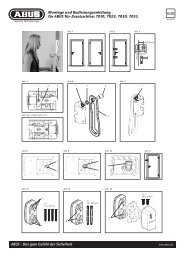
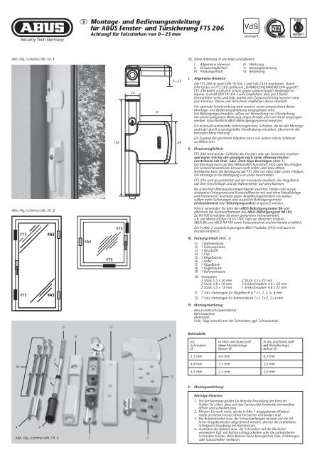
D Montage- <strong>und</strong> Bedienungsanleitung<br />
für ABUS Fenster- <strong>und</strong> <strong>Türsicherung</strong> <strong>FTS</strong> <strong>206</strong><br />
Achtung! für Falzstärken von 0 – 25 mm<br />
FAS<br />
1<br />
<strong>FTS</strong><br />
12<br />
156<br />
<strong>FTS</strong><br />
24<br />
7<br />
51<br />
8<br />
11<br />
0–25<br />
69<br />
D Diese Anleitung ist wie folgt untergliedert:<br />
I. Allgemeine Hinweise IV. Werkzeug<br />
II. Einsatzmöglichkeit V. Montageanleitung<br />
III. Packungsinhalt VI. Bedienung<br />
I. Allgemeine Hinweise<br />
Die <strong>FTS</strong> <strong>206</strong> ist nach DIN 18104-1 <strong>und</strong> VdS 2536 anerkannt. Durch<br />
DIN Certco ist <strong>FTS</strong> <strong>206</strong> zertifiziert „EINBRUCHHEMMEND DIN-geprüft“.<br />
<strong>FTS</strong> <strong>206</strong> bietet zusätzlich Schutz gegen unberechtigtes Eindringen in<br />
Räume. Gemäß DIN 18104-1 wird empfohlen, dass pro 1 Meter<br />
Fensterhöhe rechts <strong>und</strong> links jeweils eine Zusatzsicherung montiert wird<br />
(pro Fenster). Polizei <strong>und</strong> Versicherer empfehlen dieses ebenfalls.<br />
Die optimale Schutzwirkung wird erreicht, wenn entsprechend dieser<br />
Montage- <strong>und</strong> Bedienungsanleitung vorgegangen wird.<br />
Die Befestigungsschrauben sollten zur Vermeidung von Überdrehung<br />
mit einem geeigneten Werkzeug eingeschraubt <strong>und</strong> von Hand angezogen<br />
werden. Ausschließlich ABUS-Befestigungsmaterial einsetzen.<br />
Für eventuell auftretende Verletzungen bzw. Schäden, die bei der Montage<br />
<strong>und</strong>/oder durch unsachgemäße Handhabung entstehen, übernimmt der<br />
Hersteller keine Haftung!<br />
Ein Zugang des gesamten Objektes muss von außen mittels Schlüssel<br />
zu öffnen sein.<br />
II. Einsatzmöglichkeit<br />
<strong>FTS</strong> <strong>206</strong> wird auf der Griffseite des Fensters oder der Fenstertür montiert<br />
<strong>und</strong> eignet sich für alle gängigen nach innen öffnende Fenster/<br />
Fenstertüren mit Dreh- oder -Dreh-Kipp-Beschlägen (Abb. 1).<br />
Die Montage kann auf den Werkstoffen Kunststoff, Holz oder Alu erfolgen.<br />
Die Fenster/Fenstertüren können nach rechts oder links öffnen.<br />
Wahlweise kann die Betätigung der <strong>FTS</strong> <strong>206</strong> von oben oder unten erfolgen.<br />
Die Montage ist für Betätigung von unten beschrieben.<br />
<strong>FTS</strong> <strong>206</strong> wird gr<strong>und</strong>sätzlich auf der Innenseite montiert, das Flügelblech<br />
auf dem Fensterflügel <strong>und</strong> die Rahmenleiste auf dem Rahmen.<br />
Bei schlechten Befestigungsmöglichkeiten (weicher, hohler oder ausgeschäumter<br />
Untergr<strong>und</strong> <strong>und</strong> Kunststofffenster mit <strong>und</strong> ohne Metalleinlage<br />
<strong>und</strong> Holzfenster) <strong>und</strong>/oder guten Angriffsmöglichkeiten von außen,<br />
sollten mehr Sicherungen <strong>und</strong> zusätzlich Befestigungsmittel<br />
(Verb<strong>und</strong>mörtel oder Befestigungsanker) eingesetzt werden.<br />
Hierzu verwenden Sie bitte den ABUS-Befestigungsanker BA oder<br />
alternativ bei Kunststoffrahmen das ABUS-Befestigungsset IM 100.<br />
Zu IM 100 benötigen Sie einen geeigneten Verb<strong>und</strong>mörtel,<br />
z.B. der Marke Fischer FIS VS 150C oder ein ähnliches Produkt.<br />
ABUS BA <strong>und</strong> ABUS IM 100 sowie Verb<strong>und</strong>mörtel sind im Handel erhältlich.<br />
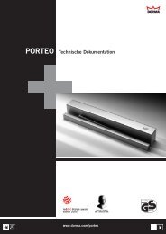
Die in Abb. 2 zusätzlich gezeigten ABUS-Produkte (FAS) sind auch im<br />
Handel erhältlich.<br />
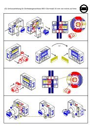
III. Packungsinhalt (Abb. 3)<br />
11. 1 Rahmenleiste<br />
12. 1 Führungshülse<br />
13. 1 Druckstift<br />
14. 1 Clip<br />
15. 1 Riegelbolzen<br />
16. 1 Feder<br />
17. 1 Flügelblech<br />
18. 1 Flügelhaube<br />
19. 1 Rahmenhaube<br />
10. Schrauben:<br />
1 Stück 5,5 x 50 mm 2 Stück 3,5 x 25 mm<br />
2 Stück 4,8 x 50 mm 3 Senkschrauben 4,8 x 50 mm<br />
2 Stück 3,5 x 13 mm 1 Senkschrauben 4,8 x 22 mm<br />
11. 1 Satz Unterlagen für Flügelblech je 1x1, 2, 3, 4, 8 mm<br />
12. 1 Satz Unterlagen für Rahmenleiste 1x1, 1x 2, 2 x 4 mm<br />
IV. Montagewerkzeug<br />
Kreuzschlitzschraubendreher<br />
Bohrmaschine<br />
Metermaß<br />
Feile, Säge zum Kürzen der Schrauben, ggf. Schraubstock<br />
Bohrtabelle<br />
für<br />
Schrauben<br />
Ø<br />
5,5 mm<br />
4,8 mm<br />
3,5 mm<br />
V. Montageanleitung:<br />
In Holz <strong>und</strong> Kunststoff<br />
ohne Metalleinlage<br />
Bohrer Ø<br />
4,0 mm<br />
3,5 mm<br />
In Alu <strong>und</strong> Kunststoff<br />
mit Metalleinlage<br />
Bohrer Ø<br />
4,5 mm<br />
3,5 mm<br />
2,5 mm 3,0 mm<br />
Wichtige Hinweise:<br />
1. Vor der Montage prüfen Sie bitte die Einstellung des Fensters.<br />
Stellen Sie sicher, dass sich das Fenster/die Fenstertür einwandfrei<br />
öffnen <strong>und</strong> schließen lässt.<br />
2. Messen Sie auch nach, ob die in Abb. 1 angegebenen Mindestmaße<br />
an Ihrem Fenster/Ihrer Fenstertür vorhanden sind.<br />
3. Die Bohrlochtiefen bzw. die Schraubenlängen müssen auf die örtlichen<br />
Gegebenheiten abgestimmt werden, ebenso die empfohlene<br />
Schrägverschraubung bei Holzfenstern.<br />
4. Austreten des Bohrers bzw. der Schrauben auf der Rückseite<br />
vermeiden! Ggf. mit Bohranschlag arbeiten oder die vorhandenen<br />
Schrauben kürzen. Beim Bohren keine beweglichen Teile, Dichtungen<br />
oder Glasscheiben verletzen.
G These instructions are organised in the following sections:<br />
I. General instructions IV. Tools<br />
II. Possible uses V. Installation instructions<br />
III. Pack contents VI. Operation<br />
I. General instructions<br />
The <strong>FTS</strong> <strong>206</strong> is recognised as complying with the strict test requirements<br />
of DIN 18104-1 and VdS 2536.<br />
<strong>FTS</strong> <strong>206</strong> is certified by DIN Certco as “BURGLAR RETARDANT DIN tested”.<br />
<strong>FTS</strong> <strong>206</strong> offers additional protection from unauthorised intruders in your<br />
rooms. DIN 18104-1 recommends that an additional security device<br />
should be fitted on the left and right for every meter in height (per window).<br />
The police and insurance companies also give the same recommendation.<br />
Optimum protection can be achieved by proceeding according to these<br />
installation and operation instructions. To prevent the risk of overtightening,<br />
the fastening screws should by screwed in using a suitable tool and<br />
tightened by hand. Only use ABUS fastening material.<br />
The manufacturer does not assume any liability for possible injuries<br />
or damages caused during installation and/or by incorrect handling!<br />
II. Possible uses<br />
<strong>FTS</strong> <strong>206</strong> is mounted on the handle side of the window or French door<br />
and is suitable for all common windows/French doors opening<br />
to the inside with turn or turn-and-tilt hardware (fig. 1).<br />
The lock can be fitted to wood, PVC or aluminium.<br />
The windows/French doors can open to the right or left.<br />
The security device <strong>FTS</strong> <strong>206</strong> can be activated from top or bottom.<br />
The described installation procedure is for activation from the bottom.<br />
<strong>FTS</strong> <strong>206</strong> is always mounted to the inside, with the casement plate on the<br />
window casement and the frame strip on the frame.<br />
In poor fixture conditions (soft or hollow or foam base and PVC windows<br />
with and without metal inlay and wooden windows) and/or good<br />
possibilities for intrusion from the outside, more security devices and<br />
additional fastenings should be used (composite mortar or fixing bolts).<br />
To do so, please use the ABUS fixing bolt BA or alternatively for PVC<br />
frames, the ABUS fastening set IM 100. For IM 100 you need a suitable<br />
composite mortar, e.g. Fischer FIS VS 150C or similar. ABUS BA and<br />
ABUS IM 100 are available from retail stores together with composite<br />
mortar.<br />
The ABUS products (FAS) shown in fig. 2 are also available from retail<br />
stores.<br />
III. Pack contents (fig. 3)<br />
11. 1 frame strip<br />
12. 1 guide sleeve<br />
13. 1 pressure pin<br />
14. 1 clip<br />
15. 1 locking bolt<br />
16. 1 spring<br />
17. 1 casement plate<br />
18. 1 casement cover<br />
19. 1 frame cover<br />
10. Screws:<br />
1 each 5.5 x 50 mm 2 each 3.5 x 25 mm<br />
2 each 4.8 x 50 mm 3 countersunk screws 4.8 x 50 mm<br />
2 each 3.5 x 13 mm 1 countersunk screws 4.8 x 22 mm<br />
11. 1 set of shims for casement plate, 1x1, 2, 3, 4, 8 mm each<br />
12. 1 set of shims for frame strip, 1x1, 1x 2, 2 x 4 mm each<br />
IV. Installation tools<br />
Phillips screwdriver<br />
Drill<br />
Yardstick<br />
Saw, file for shortening the screws, possibly vice<br />
Drilling table<br />
for<br />
screws<br />
Ø<br />
5.5 mm<br />
4.8 mm<br />
3.5 mm<br />
in wood and PVC<br />
without metal inlay<br />
drill bit Ø<br />
4.0 mm<br />
3.5 mm<br />
V. Installation instructions:<br />
G Installation and operation instructions<br />
for ABUS window and door lock <strong>FTS</strong> <strong>206</strong><br />
Important! for rabbet thicknesses of 0 – 25 mm<br />
F Instructions de montage<br />
pour verrou ABUS <strong>FTS</strong> <strong>206</strong><br />
Attention! pour des épaisseurs de plis de 0 à 25 mm<br />
in aluminium and PVC<br />
with metal inlay<br />
drill bit Ø<br />
4.5 mm<br />
3.5 mm<br />
2.5 mm 3.0 mm<br />
• Before installation, please check the setting of the window<br />
or French door.<br />
• If necessary, readjust the fittings so that the window (French door)<br />
opens and closes perfectly.<br />
• Also check whether your window/French door complies with the<br />
minimum dimensions shown in fig. 1.<br />
• The depths of the drilled holes and screw lengths must be adjusted<br />
to the local conditions, also the recommended angled screw<br />
connection wooden windows.<br />
• Avoid the drill or screws from coming out at the back!<br />
Possibly work with drill stopper or shorten the existing screws.<br />
• When drilling, do not damage any moving parts, seals or glass panes.<br />
F Ce manuel comporte les chapitres suivants:<br />
I. Conseils d’ordre général IV. Outillage<br />
II. Application V. Instructions d’installation<br />
III. Liste de colisage VI. Utilisation<br />
I. Conseils d’ordre général<br />
La <strong>FTS</strong> <strong>206</strong> satisfait aux exigences de contrôle sévères des normes<br />
DIN 18104-1 et VdS 2536. Le certificat DIN indique que <strong>FTS</strong> <strong>206</strong><br />
a obtenu la qualification «anti-effraction DIN».<br />
<strong>FTS</strong> <strong>206</strong> offre en plus une protection contre les intrusions par effraction<br />
dans votre logement. Selon la norme DIN 18104-1, il est recommandé<br />
de monter une sécurité complémentaire par mètre de hauteur de fenêtre,<br />
à gauche comme à droite. La police et les compagnies d’assurance le<br />
recommandent également. Pour un effet de protection optimal, suivez les<br />
instructions de ce manuel d’installation et d’utilisation. Afin d’éviter un<br />
serrage abusif, vissez et serrez les vis de fixation à la main et avec un<br />
outillage adéquat. Utilisez exclusivement des accessoires ABUS.<br />
Le fabricant n’assume aucune responsabilité pour d’éventuels blessures<br />
ou dégâts causés pendant l’installation et/ou par suite de manipulations<br />
inappropriées! L’ensemble doit être accessible de l’extérieur afin de l’ouvrir<br />
au moyen d’une clé.<br />
II. Application<br />
<strong>FTS</strong> <strong>206</strong> est monté sur le côté paumelles de la fenêtre ou de la portefenêtre<br />
et convient pour toutes les fenêtres/portes-fenêtres courantes,<br />
ouvrant vers l’intérieur et pourvues de quincaillerie battante ou oscillobattante<br />
avec commande d’une seule main (schéma 1).<br />
L’installation peut être effectuée sur des cadres en bois, en PVC ou en<br />
aluminium. Les fenêtres/portes-fenêtres peuvent s’ouvrir à gauche ou<br />
à droite. La commande de <strong>FTS</strong> <strong>206</strong> peut être effectuée par le haut ou par<br />
le bas. L’installation décrite correspond à une commande par le bas.<br />
<strong>FTS</strong> <strong>206</strong> est monté en principe du côté intérieur, la platine d’ancrage sur<br />
l’ouvrant et le socle de fixation sur le dormant.<br />
En cas de possibilités de fixation défavorables (fenêtres en boîs ou en<br />
PVC), plusieurs sécurités et des fixations supplémentaires (ancre de<br />
fixation ou mortier) doivent être prévues.<br />
Pour cela, utilisez les ancres de fixation ABUS BA (pour fenêtres en PVC,<br />
en bois ou en aluminium) ou l’ensemble de fixations ABUS IM 100<br />
(pour fenêtres en PVC).<br />
Pour IM 100, un mortier approprié est requis, par exemple FIS VS 150C<br />
de la marque Fischer, HFX de la marque Hilti ou un produit similaire.<br />
ABUS BA et ABUS IM 100 ainsi que le mortier de fixation sont disponibles<br />
dans le commerce.<br />
Les produits ABUS complémentaires illustrés en schéma 2 (FAS) sont<br />
également disponibles dans le commerce.<br />
III. Liste de colisage (schéma 3)<br />
11. 1 socle de fixation<br />
12. 1 tuyau de guidage<br />
13. 1 tige d’appui<br />
14. 1 circlip<br />
15. 1 pêne de verrouillage<br />
16. 1 ressort<br />
17. 1 platine d’ancrage<br />
18. 1 cache pour platine<br />
19. 1 cache pour socle<br />
10. Vis:<br />
1 pièce de 5,5 x 50 mm 2 pièces de 3,5 x 25 mm<br />
2 pièces de 4,8 x 50 mm 3 vis à tête conique de 4,8 x 50 mm<br />
2 pièces de 3,5 x 13 mm 1 vis à tête conique de 4,8 x 22 mm<br />
11. 1 ensemble d’entretoises pour platine d’ancrage chacun 1x1, 2, 3, 4, 8 mm<br />
12. 1 ensemble d’entretoises pour socle de fixation chacun 1x1, 1x 2, 2 x 4 mm<br />
IV. Outillage requis<br />
Tournevis cruciforme<br />
Perceuse<br />
Mètre ruban<br />
Lime, scie pour raccourcir les vis, tournevis<br />
Tableau de perçage<br />
pour<br />
vis<br />
de Ø<br />
5,5 mm<br />
4,8 mm<br />
3,5 mm<br />
dans châssis bois et PVC<br />
sans armature métallique<br />
foret Ø<br />
4,0 mm<br />
3,5 mm<br />
V. Instructions d’installation:<br />
dans châssis aluminium et PVC<br />
avec armature métallique<br />
foret Ø<br />
4,5 mm<br />
3,5 mm<br />
2,5 mm 3,0 mm<br />
Indications importantes:<br />
• Avant l’installation, contrôlez l’ouverture de la fenêtre. Assurezvous<br />
que la fenêtre/porte-fenêtre ouvre et ferme parfaitement.<br />
• Vérifiez si votre fenêtre/porte-fenêtre comporte les dimensions<br />
minimales indiquées en schéma 1.<br />
• Les profondeurs de perçage ou plutôt les longueurs des vis ainsi que<br />
les pas de vis en biais sur les fenêtres en bois doivent être adaptées<br />
aux conditions locales.<br />
• Evitez le dépassement de perçage ou de vis sur la face arrière!<br />
Le cas échéant, utilisez une butée de perçage ou raccourcissez<br />
les vis de fixation.<br />
• Lors du perçage, évitez d’endommager les éléments mobiles,<br />
les joints ou les vitres.
n Deze montage- en bedieningsinstructie is als volgt onderverdeeld:<br />
I. Algemeen IV. Gereedschap<br />
II. Toepassing V. Montage<br />
III. Verpakkingsinhoud VI. Bediening<br />
I. Algemeen<br />
<strong>FTS</strong> <strong>206</strong> voor naar binnen draaiende draai/kiep elementen.<br />
<strong>FTS</strong> <strong>206</strong> is volgens keuringseisen NEN 5096 SKG gecertificeerd.<br />
De <strong>FTS</strong> <strong>206</strong> biedt daarnaast bescherming tegen onbevoegd binnendringen<br />
van uw woning. Advies: monteer aan de scharnierzijde voor<br />
maximale veiligheid 2 stuks per 1 meter raamhoogte.<br />
Op kunststof zonder metalen kern dient u deze opleggrendel in<br />
combinatie met ABUS BA bevestigingsanker te monteren.<br />
Optioneel verkrijgbaar, zie voor montage in de handleiding van BA.<br />
Optimale veiligheid wordt bereikt door nauwkeurig opvolgen van deze<br />
montage- en gebruiksaanwijzing. Om overexpansie of doldraaien van de<br />
bevestigingsschroeven te vermijden, draait u handmatig en met passend<br />
gereedschap de schroeven vast.<br />
Voor eventueel verwondingen en/of schade tijdens montage en/of<br />
door ondesk<strong>und</strong>ig gebruik ontstaan, aanvaardt de fabrikant geen<br />
aansprakelijkheid!<br />
II. Toepassing<br />
De <strong>FTS</strong> <strong>206</strong> wordt aan de sluitzijde gemonteerd en is geschikt voor alle<br />
naar binnen draaiende ramen en deuren met draai/kiep-beslag (afb. 1).<br />
Montage mogelijk op hout, kunststof of aluminium. Rechts of links<br />
draaiend. Hoewel de bediening van de vergrendeling van onder- of van<br />
bovenaf plaats kan vinden wordt in deze montage- en bedieningsinstrictie<br />
uitgegaan van een bediening van onderaf.<br />
De <strong>FTS</strong> <strong>206</strong> wordt uitsluitend aan de binnenzijde gemonteerd;<br />
de raamplaat op het raam of deur en de kozijnlijst op het kozijn.<br />
Bij zacht hout, kunststof of aluminium dienen meerdere sloten en extra<br />
bevestigingsmiddelen (bevestigings- of chemische ankers) toegepast te<br />
worden. Hiervoor kunt u het ABUS bevestigingsanker BA (zacht hout,<br />
kunststof, aluminium) gebruiken (in schroefgat A).<br />
ABUS BA zijn in de handel verkrijgbaar.<br />
De in afb. 2 extra getoonde ABUS producten (FAS) zijn eveneens in de<br />
handel verkrijgbaar.<br />
III. Verpakkingsinhoud (afb. 3)<br />
11. 1 montageplaat kozijn<br />
12. 1 geleidingshuls<br />
13. 1 drukstift<br />
14. 1 clip<br />
15. 1 vergrendelingspen<br />
16. 1 veer<br />
17. 1 raamplaat<br />
18. 1 afdekkap raamplaat<br />
19. 1 afdekkap montageplaat kozijn<br />
10. Schroeven:<br />
1 stuks 5,5 x 50 mm 2 stuks 3,5 x 25 mm<br />
2 stuks 4,8 x 50 mm 3 stuks 4,8 x 50 mm met verzonken kop<br />
2 stuks 3,5 x 13 mm 1 stuks 4,8 x 22 mm met verzonken kop<br />
11. 1 set opvulplaatjes voor raamplaat 1x1, 2, 3, 4 en 8 mm<br />
12. 1 set opvulplaatjes voor montageplaat kozijn 1x1, 1x 2, 2 x 4 mm<br />
IV. Gereedschap<br />
Kruiskopschroevendraaier<br />
Boormachine<br />
Meetlat<br />
Zaag, vijl en eventueel bankschroef voor het inkorten van de schroeven<br />
Boortabel<br />
voor<br />
schroeven<br />
Ø<br />
5,5 mm<br />
4,8 mm<br />
3,5 mm<br />
V. Montage:<br />
in hout en kunststof<br />
zonder metalen kern<br />
boor Ø<br />
4,0 mm<br />
3,5 mm<br />
n Montage- en bedieningsinstructie<br />
voor ABUS opleggrendel <strong>FTS</strong> <strong>206</strong><br />
Opgelet! voor opdekdiktes van 0 – 25 mm<br />
I Istruzioni di montaggio ed uso della<br />
sicura per finestre e porte <strong>FTS</strong> <strong>206</strong><br />
Attenzione! per spessori di aggraffatura 0 – 25 mm<br />
classificatie manuele test<br />
in aluminium en kunststof<br />
met metalen kern<br />
boor Ø<br />
4,5 mm<br />
3,5 mm<br />
2,5 mm 3,0 mm<br />
zelfstandig<br />
Belangrijke aanwijzingen:<br />
1. Voor de montage dient u de afstelling van het raam resp.<br />
de deur te controleren.<br />
Zorg ervoor dat het raam / de deur probleenloos geopend<br />
en gesloten kan worden.<br />
2. Meet na of de in afb. 1 aangegeven min. afmetingen<br />
daadwerkelijk beschikbaar zijn.<br />
3. De boordieptes en schroeflengten moeten aan het gevelelement<br />
aangepast worden. Evenals de aanbevolen schuine verschroeving<br />
bij houten gevelelementen.<br />
4. Voorkom doorboren en -schroeven.<br />
Eventueel met een booraanslag werken of de schroeven inkorten.<br />
Bij het boren geen bewegende delen, afdichtingen of glas beschadigen.<br />
inbraakwerendheidsklasse<br />
NEN5096/ENV1630<br />
contacttijd /<br />
gereedschapsset<br />
RC 2 3 min. / A<br />
I Queste istruzioni si suddividono nel modo seguente:<br />
I. Istruzioni generali IV. Attrezzi<br />
II. Possibilità d’impiego V. Istruzioni di montaggio<br />
III. Contenuto della confezione VI. Uso<br />
I. Istruzioni generali<br />
La <strong>FTS</strong> <strong>206</strong> è conforme ai severi requisiti di controllo della DIN 18104-1<br />
e della VdS 2536.<br />
Con la DIN Certco essa è certificata come «ANTISCASSO conf. DIN».<br />
La <strong>FTS</strong> <strong>206</strong> garantisce una protezione in più a difesa della Vostra casa.<br />
Secondo DIN 18104-1 si consiglia di montare per ogni metro di altezza<br />
della finestra, una sicura supplementare sul lato destro e una sul lato<br />
sinistro (per ogni finestra). Anche la polizia e le compagnie d’assicurazione<br />
consigliano tali misure.<br />
Si può ottenere una protezione ottimale, procedendo secondo queste<br />
istruzioni di montaggio ed uso. Le viti di fissaggio, per evitarne un<br />
serraggio eccessivo, devono essere avvitate con un utensile adatto<br />
e poi serrate a mano.<br />
Impiegare esclusivamente materiale di fissaggio ABUS.<br />
Per eventuali ferimenti e/o danni, che si verificano durante il montaggio<br />
e/o per maneggio indebito, il produttore non si assume alcuna<br />
responsabilità!<br />
II. Possibilità d’impiego<br />
La <strong>FTS</strong> <strong>206</strong> viene montata sul lato della finestra o porta-finestra su cui<br />
si trova la maniglia ed è adatta per tutte le normali finestre e portefinestre<br />
che si aprono verso l’interno, con guarnizioni metalliche<br />
girevoli o girevoli- a bilico (ill. 1).<br />
Si può montare la <strong>FTS</strong> <strong>206</strong> su legno, plastica o alluminio.<br />
Le finestre/porte-finestre possono aprirsi verso destra o verso sinistra.<br />
A scelta la <strong>FTS</strong> <strong>206</strong> si può azionare dall’alto o dal basso.<br />
Il montaggio è descritto per azionamento dal basso.<br />
Di solito la <strong>FTS</strong> <strong>206</strong> viene montata all’interno, la lamiera del battente<br />
sul battente della finestra ed il listello del telaio sul telaio.<br />
Se le possibilità di fissaggio sono scadenti (sottofondo morbido o vuoto<br />
o riempito con espanso e finestre in plastica con o senza inserto metallico<br />
e finestre in legno) e le possibilità di effrazione dall’esterno sono buone,<br />
si dovrebbero utilizzare più sicure e mezzi di fissaggio supplementari<br />
(malta o bullone di fissaggio).<br />
Allo scopo utilizzare per favore il bullone di fissaggio ABUS BA o come<br />
alternativa, nel caso di telai in plastica, il kit di fissaggio ABUS IM 100.<br />
Per lo IM 100 serve una malta adatta, p.e. della marca Fischer FIS VS 150C<br />
o un prodotto simile. ABUS BA e ABUS IM 100 come anche la malta si<br />
possono acquistare.<br />
Anche i prodotti ABUS (FAS) raffigurati nell’ill. 2 si possono acquistare.<br />
III. Contenuto della confezione (ill. 3)<br />
11. listello del telaio<br />
12. boccola di guida<br />
13. 1 perno di spinta<br />
14. 1 clip<br />
15. 1 perno del chiavistello<br />
16. 1 molla<br />
17. 1 lamierina (per battente)<br />
18. 1 coperchietto della lamierina per battente<br />
19. 1 coperchietto per listello del telaio<br />
10. Viti:<br />
1 vite da 5,5 x 50 mm 2 viti da 3,5 x 25 mm<br />
2 viti da 4,8 x 50 mm 3 viti a testa svasata da 4,8 x 50 mm<br />
2 viti da 3,5 x 13 mm 3 viti a testa svasata da 4,8 x 22 mm<br />
11. 1 kit di spessori per ogni lamierina del battente,<br />
ciascuno 1 x 1, 2, 3, 4, 8 mm<br />
12. 1 kit di spessori per ogni listello del telaio ciascuno 1x1, 1x 2, 2 x 4 mm<br />
IV. Attrezzi da montaggio<br />
Cacciavite a stella (con punta magnetica)<br />
Trapano<br />
Sega, lima per accorciare le viti, in caso una morsa<br />
Tabella di trapanazioni<br />
per<br />
viti<br />
Ø<br />
5,5 mm<br />
4,8 mm<br />
3,5 mm<br />
in legno e plastica<br />
senza inserto metallico<br />
punta da trapano Ø<br />
4,0 mm<br />
3,5 mm<br />
V. Istruzioni per il montaggio:<br />
gebruik BA-anker<br />
houten kozijnen kunststof kozijnen<br />
zonder<br />
ABUS bevestigingsanker<br />
in combinatie met<br />
ABUS bevestigingsanker<br />
in alluminio e plastica<br />
con inserto metallico<br />
punta da trapano Ø<br />
4,5 mm<br />
3,5 mm<br />
2,5 mm 3,0 mm<br />
Avvertenze importanti:<br />
• Prima del montaggio verificare per favore la regolazione della finestra<br />
risp. della porta finestra.<br />
• Se necessario registrare nuovamente i ferramenti affinché la finestra<br />
(la porta-finestra) si chiuda e si apra perfettamente.<br />
• Verificare anche che le misure minime indicate nell’ill. 1 esistano<br />
nelle vostre finestre/porte-finestre.<br />
• Le profondità per trapanare i fori, risp. le lunghezze delle viti devono<br />
essere adattate alle condizioni particolari. Anche l’avvitazione<br />
diagonale a finestre in legno.<br />
• Evitare che la punta del trapano risp. la vite fuoriesca dall’altra parte!<br />
Se necessario lavorare con arresto del trapano o accorciare le viti.<br />
• Quando si trapana, non danneggiare parti mobili, guarnizioni o vetri.
Abb./fig.<br />
schéma<br />
afb./ill. 1<br />
Abb./fig.<br />
schéma<br />
afb./ill. 2<br />
Abb./fig.<br />
schéma<br />
afb./ill. 3<br />
Abb./fig.<br />
schéma<br />
afb./ill. 4<br />
Abb./fig./schéma/afb./ill. 5<br />
3 mm<br />
ABUS - Das gute Gefühl der Sicherheit<br />
B<br />
A<br />
B<br />
B Ø 3,5<br />
A Ø 4,0<br />
B Ø 3,5<br />
4,8 x 50<br />
5,5 x 50<br />
4,8 x 50<br />
ca.<br />
40<br />
mm<br />
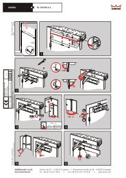
Montage/Installation/Installation/Montage/Montaggio<br />
D Rahmenleiste positionieren. Bohrlöcher A + B anzeichnen.<br />
> 3 mm < Abstand.<br />
Hilfsmittel: Unterlage für Rahmenleiste 2 mm einschließlich Nocken<br />
= 3 mm.<br />
G Position frame batten. Mark drill holes A + B.<br />
> 3 mm < distance.<br />
Accessories: Base for frame batten 2 mm including pins = 3 mm.<br />
F Positionner la lisière du cadre. Dessiner les trous de perçage A + B.<br />
> 3 mm < ecart.<br />
Aide: Support pour la lisière du cadre 2 mm, stries incluses = 3 mm.<br />
n Montageplaat kozijn plaatsen. Boorgaten A + B markeren.<br />
> 3 mm < afstand.<br />
Hulpmiddel: Ondergrond voor kader 2 mm inclusief kam = 3 mm.<br />
I Posizionare la cornice del telaio. Segnare i fori A + B.<br />
Distanza > 3 mm
Abb./fig.<br />
schéma<br />
afb./ill. 6<br />
Abb./fig.<br />
schéma<br />
afb./ill. 7<br />
Abb./fig.<br />
schéma<br />
afb./ill. 8<br />
Löcher „C“<br />
anzeichnen<br />
Mark holes<br />
“C”<br />
Dessiner<br />
les trous «C»<br />
Gaten „C”<br />
markeren<br />
Segnare<br />
i fori «C»<br />
Abb./fig.<br />
schéma<br />
afb./ill. 9<br />
Abb./fig.<br />
schéma<br />
afb./ill. 10<br />
C<br />
C<br />
Ø 2,5<br />
ABUS - Das gute Gefühl der Sicherheit<br />
C<br />
D Druckstifteinheit einschieben.<br />
G Push in pressure pin unit.<br />
F Insérer l’ensemble des chevilles de pression.<br />
n Druckstift inschuiven.<br />
I Inserire l’unità del perno a pressione.<br />
D Clip aufdrücken (muss auf beiden Seiten einrasten).<br />
G Press on clip (must lock into place on both sides).<br />
F Pousser le clip (doit verrouiller des deux côtés).<br />
n Clip indrukken (moet aan beide kanten inschuiven).<br />
I Premere sulla clip (deve arrestarsi a scatto da entrambi i lati).<br />
D Flügelblech positionieren, dabei evtl. mit Kunststoffunterlagen unterlegen.<br />
Bei Falzdicke: 17 mm 16 mm = 1 mm Unterlage<br />
keine <br />
Unterlage 0 mm = 17 mm Unterlage<br />
G Position casement plate, <strong>und</strong>erlaying with plastic <strong>und</strong>erlays if necessary.<br />
With rabbet 17 mm 16 mm = 1 mm <strong>und</strong>erlay<br />
thickness: no <br />
<strong>und</strong>erlay 0 mm = 17 mm <strong>und</strong>erlay<br />
F Positionner la tôle pliée, glisser éventuellement un support<br />
en plastique en dessous.<br />
Pour une 17 mm 16 mm = support de 1 mm<br />
épaisseur pas de <br />
de plis: support 0 mm = support de 17 mm<br />
n Raamplaat positioneren, daarbij eventueel kunststof opvulplaatjes<br />
aanbrengen.<br />
Bij sponningdikte: 17 mm 16 mm = onderlaag van 1 mm<br />
geen <br />
onderlaag 0 mm = onderlaag van 17 mm<br />
I Posizionare la lamiera a battente, eventualmente inserire spessori di plastica.<br />
Con spessore 17 mm 16 mm = 1 mm di spessore<br />
dell’aggraffatura: nessuno <br />
spessore<br />
D Löcher „C“ vorbohren.<br />
G Pre-drill holes “C”.<br />
F Prépercer les trous «C».<br />
n Gaten „C” voorboren.<br />
I Sbozzare i fori «C».<br />
0 mm = 17 mm di spessore<br />
D Flügelblech anschrauben, eventuell mit Unterlagen.<br />
Schrauben 3,5 x 13 oder je nach Unterlagen 3,5 x 25.<br />
G Screw on casement plate,<br />
3.5 x 13 or 3.5 x 25 depending on <strong>und</strong>erlays.<br />
F Visser la tôle pliée,<br />
en fonction du support 3,5 x 13 ou 3,5 x 25.<br />
n Raamplaat vastschroeven,<br />
eventueel met onderlegplaaten 3,5 x 13 of 3,5 x 25.<br />
I Avvitare la lamiera a battente,<br />
a seconda degli spessori 3,5 x 13 o 3,5 x 25.<br />
www.abus.com<br />
DTechnische Änderungen vorbehalten. Für Irrtümer <strong>und</strong> Druckfehler keine Haftung. ABUS © 2011<br />
GSubject to technical alterations. No liability for mistakes and printing errors. ABUS © 2011<br />
FNous nous réservons le droit de toutes modifications techniques. Nous n’assumons aucune responsabilité pour des erreurs ou défauts d’impression éventuels. ABUS © 2011<br />
nTechnische wijzigingen voorbehouden. Geen aansprakelijkheid voor vergissingen en drukfouten. ABUS © 2011<br />
ICi si riservano modifiche tecniche. Per errori e refusi di stampa non ci si assume alcuna responsabilità. ABUS © 2011
Abb./fig.<br />
schéma<br />
afb./ill. 11<br />
Abb./fig.<br />
schéma<br />
afb./ill. 12<br />
Abb./fig.<br />
schéma<br />
afb./ill. 13<br />
Abb./fig.<br />
schéma<br />
afb./ill. 14<br />
Abb./fig.<br />
schéma<br />
afb./ill. 15<br />
ABUS - Das gute Gefühl der Sicherheit<br />
D<br />
D1<br />
D<br />
Ø 3,5<br />
D 4,8x50<br />
D 4,8x50<br />
D1<br />
4,8x50<br />
(22)<br />
D Funktion überprüfen, dazu Fenster öffnen <strong>und</strong> schließen,<br />
eventuell Flügelblech nachjustieren.<br />
G Check that it functions by opening and closing window,<br />
perhaps readjusting casement plate.<br />
F Contrôler le functionnement, ouvrir et fermer la fenêtre,<br />
ajuster éventuellement la tôle pliée.<br />
n Controleer werking door het raam te openen en te sluiten.<br />
Eventueel raamplaat afstellen.<br />
I Controllare il funzionamento, a tale scopo chiudere e aprire la finestra,<br />
eventualmente regolare la lamiera a battente.<br />
D Schraublöcher D <strong>und</strong> D1 vorbohren (bei D1 Fensterbeschlag nicht<br />
beschädigen). Bei Holzfenstern die beiden vorderen Löcher (D) leicht<br />
schräg, bis max. 20° Neigung Richtung Fenstermitte vorbohren.<br />
G Pre-drill screw holes “D” and “D1” (with D1 do not damage window<br />
fitting). On wooden windows pre-drill the two front holes slightly at an<br />
angle, up to max. 20° in the direction of the window center.<br />
F Pré-percer les trous «D» et D1 (pour D1 Attention à ne pas endommager<br />
la garniture de la fenêtre). Sur des fenêtres en bois, pré-percer les 2 trous<br />
de devant avec une inclinaison de maximum 20° en direction du milieu de<br />
la fenêtre.<br />
n Schroefgaten D en D1 voorboren (bij D1 raambeslag niet beschadigen).<br />
Bij houten gevelelementen de beide gaten vooraan (D) licht schuin,<br />
tot max. 20°, richting het midden van het raam voorboren.<br />
I Sbozzare i fori D (con D1 non danneggiare la ferramenta della finestra).<br />
Da finestre in legno forare i due buchi (D) con una inclinazione di al<br />
massimo 20° in direzione del centro della finestra.<br />
D Flügelblech anschrauben (bei umlaufendem Beschlag D1 = 4,8 x 22).<br />
G Screw on casement plate (with continuous fitting D1 = 4.8 x 22).<br />
F Visser la tôle pliée (pour garniture d’une circonférence de D1 = 4,8 x 22).<br />
n Raamplaat vastschroeven (bij beslag rondom D1 = 4,8 x 22).<br />
I Avvitare la lamiera a battente (con ferramenta perimetrale D1 = 4,8 x 22).<br />
D Rahmenhaube aufsetzen.<br />
G Put frame cover in place.<br />
F Poser l’armature du cadre.<br />
n Afdekkap montageplaat opzetten.<br />
I Montare la scossalina del telaio.<br />
D Flügelhaube aufsetzen.<br />
G Put casement cover in place.<br />
F Poser l’armature «ailée».<br />
n Afdekkap raamplaat opzetten.<br />
I Montare la scossalina del battente.<br />
www.abus.com<br />
DTechnische Änderungen vorbehalten. Für Irrtümer <strong>und</strong> Druckfehler keine Haftung. ABUS © 2011<br />
GSubject to technical alterations. No liability for mistakes and printing errors. ABUS © 2011<br />
FNous nous réservons le droit de toutes modifications techniques. Nous n’assumons aucune responsabilité pour des erreurs ou défauts d’impression éventuels. ABUS © 2011<br />
nTechnische wijzigingen voorbehouden. Geen aansprakelijkheid voor vergissingen en drukfouten. ABUS © 2011<br />
ICi si riservano modifiche tecniche. Per errori e refusi di stampa non ci si assume alcuna responsabilità. ABUS © 2011
Abb./fig.<br />
schéma<br />
afb./ill. 16<br />
Abb./fig.<br />
schéma<br />
afb./ill. 17<br />
Abb./fig.<br />
schéma<br />
afb./ill. 18<br />
ABUS - Das gute Gefühl der Sicherheit<br />
VI. Bedienung/Operation/Utilisation/Bediening/Uso<br />
D Stufe 0 = Fenstersicherung geöffnet.<br />
G Stage 0 = Window security device open.<br />
F Niveau 0 = Dispositif de sécurité pour fenêtre ouverte.<br />
n Stand 0 = Raambeveiliging geopend.<br />
I Livello 0 = Sicurezza finestra aperta.<br />
D Stufe 1 = Fenstersicherung verriegelt, öffnen ohne Schlüssel.<br />
Druckstift bis zur ersten Rastung eindrücken.<br />
Zum Öffnen Druckstift wieder bis zur ersten Rastung<br />
eindrücken <strong>und</strong> loslassen.<br />
G Stage 1 = window security device locked, open without key.<br />
Press pressure pin in until the first catch.<br />
To open, press pressure pin in again to the first catch<br />
and release.<br />
F Niveau 1 = Dispositif de sécurité pour fenêtre verrouillée,<br />
à ouvrir sans clef. Pousser la cheville de pression jusqu’au<br />
premier verrouillage. Pour ouvrir, pousser la cheville de<br />
pression à nouveau jusqu’au premier verrouillage et la lâcher.<br />
n Stand 1 = Raambeveiliging vergrendeld, openen zonder sleutel.<br />
Druk de drukstift tot de eerste blokkeerstand.<br />
Openen, de drukstift tot de eerste blokkeerstand indrukken<br />
en loslaten.<br />
I Livello 1 = Sicurezza finestra bloccata, apertura senza chiave.<br />
Premere il perno fino alla prima tacca.<br />
Per aprire premere di nuovo il perno fino alla prima tacca<br />
e poi rilasciare.<br />
D Stufe 2 = Fenstersicherung verriegelt, öffnen nur mit Schlüssel<br />
möglich. Druckstift bis zur zweiten Rastung eindrücken.<br />
Zum Öffnen Schlüssel drehen, anschließend Druckstift bis zur<br />
ersten Rastung eindrücken <strong>und</strong> loslassen.<br />
G Stage 2 = window security device locked,<br />
can be opened with key.<br />
Press pressure pin in until second catch.<br />
To open, turn key then press pressure pin in to the first catch<br />
and release.<br />
F Niveau 2 = Dispositif de sécurité pour fenêtre verrouillée,<br />
à ouvrir sans une clef.<br />
Pousser la cheville de pression jusqu’au deuxième verrouillage.<br />
Pour ouvrir, tourner la clef, ensuite pousser la cheville<br />
de pression jusqu’au deuxième verrouillage et la lâcher.<br />
n Stand 2 = Raambevestiging is afgesloten, enkel met sleutel<br />
te openen. Druk de drukstift in tot de tweede blokkeerstand.<br />
Om te openen moet u aan de sleutel draaien, vervolgens de<br />
drukstift tot de eerste inkeping indrukken en daarna loslaten.<br />
I Livello 2 = Sicurezza finestra bloccata,<br />
l’apertura è possibile esclusivamente con la chiave.<br />
Premere il perno fino alla seconda tacca.<br />
Per aprire girare la chiave, poi premere il perno fino alla<br />
prima tacca e rilasciare.<br />
D Empfehlung:<br />
Druckstift von Verriegelungsstufe 0 ohne Unterbrechung direkt in Verriegelungsstufe 2 eindrücken.<br />
G Recommendation:<br />
Druckstift von Verriegelungsstufe 0 ohne Unterbrechung direkt in Verriegelungsstufe 2 eindrücken.<br />
F Conseil:<br />
Pousser la cheville de pression directement et sans interruption, du niveau 0 au niveau 2.<br />
n Aanbeveling:<br />
Druk de drukstift zonder onderbreking direct van blokkeerstand 0 in de blokkeerstand 2.<br />
I Consiglio:<br />
Premere il perno dal livello di bloccaggio 0 senza interruzione direttamente nel livello di bloccaggio 2.<br />
www.abus.com<br />
DTechnische Änderungen vorbehalten. Für Irrtümer <strong>und</strong> Druckfehler keine Haftung. ABUS © 2011<br />
GSubject to technical alterations. No liability for mistakes and printing errors. ABUS © 2011<br />
FNous nous réservons le droit de toutes modifications techniques. Nous n’assumons aucune responsabilité pour des erreurs ou défauts d’impression éventuels. ABUS © 2011<br />
nTechnische wijzigingen voorbehouden. Geen aansprakelijkheid voor vergissingen en drukfouten. ABUS © 2011<br />
ICi si riservano modifiche tecniche. Per errori e refusi di stampa non ci si assume alcuna responsabilità. ABUS © 2011<br />
390333 1/11