und Bedienungsanleitung für ABUS Fenstergriff-Schloss FO 400 - Skg
und Bedienungsanleitung für ABUS Fenstergriff-Schloss FO 400 - Skg
und Bedienungsanleitung für ABUS Fenstergriff-Schloss FO 400 - Skg

You also want an ePaper? Increase the reach of your titles
YUMPU automatically turns print PDFs into web optimized ePapers that Google loves.
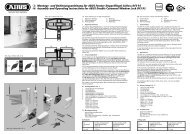
D Montage des <strong>Schloss</strong>kastens<br />
1. Vorhandenen <strong>Fenstergriff</strong> in Offenstellung bringen <strong>und</strong> Schrauben<br />
herausdrehen. Fenster wieder mit altem Stift verschließen <strong>und</strong> Griff<br />
abnehmen.<br />
2. <strong>Schloss</strong>kasten (1) <strong>FO</strong> <strong>400</strong> demontieren (Abb. 3):<br />
Abdeckhaube abnehmen, Schraube herausdrehen. Riegelblech,<br />
Riegel <strong>und</strong> Drehhülse aus dem <strong>Schloss</strong>gehäuse herausnehmen<br />
(Vorsicht, der lose Antriebsstift kann herausfallen).<br />
3. Gr<strong>und</strong>platte mit beigefügten Senkschrauben M5 x 35 mm<br />
anschrauben (Abb. 4a). Falls keine metrischen Gewindelöcher<br />
vorhanden sind, müssen die beiden beigefügten Schrauben<br />
4,8 x 25 mm verwendet werden. Mit Drehhülse <strong>und</strong> eingestecktem<br />
Vierkantstift (7 oder 8) Position prüfen (Abb. 4b).<br />
4. Länge des Vierkantstiftes bestimmen:<br />
Länge des Vierkantstiftes an abgeschraubtem <strong>Fenstergriff</strong> messen<br />
(Abb. 5). Kurzen Vierkantstift (7) mit langer Seite in die Drehhülse<br />
stecken. Wird das festgestellte Maß nicht erreicht, langen Vierkantstift<br />
(8) verwenden <strong>und</strong> eventuell auf das Maß „X“ entsprechend<br />
kürzen.<br />
5. Drehhülse <strong>und</strong> Vierkantstift (7 oder 8) in die Gr<strong>und</strong>platte stecken.<br />
Nocken der Drehhülse auf Markierung „R“ oder „L“ einstellen.<br />
(Fenster öffnet nach rechts = „R“; nach links = „L“) (Abb. 6)<br />
6. Schließprobe:<br />
<strong>Schloss</strong>gehäuse (Griff zeigt nach unten) auf die Gr<strong>und</strong>platte<br />
stecken. Drehgriff um 90° (bei Drehkippfenstern 180°) hin <strong>und</strong> her<br />
drehen. <strong>Schloss</strong>gehäuse wieder abnehmen. Bei schwergängiger<br />
Schließprobe Senkschraube M5 x 35 mm (oder 4,8 x 25 mm) lösen<br />
<strong>und</strong> Gr<strong>und</strong>platte etwas verlagern.<br />
7. Durch die Löcher D des <strong>Schloss</strong>kastens (1) vorbohren,<br />
(s. Bohrtabelle) <strong>und</strong> <strong>Schloss</strong>kasten (1) mit Schrauben 5,5 x 60 mm<br />
festschrauben (Abb. 19).<br />
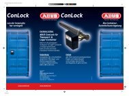
Bohren der Schließkastenseite (Rahmen) <strong>und</strong> Bestimmen<br />
des Riegeleinstellmaßes<br />
1. Einwegschablonen-Hälften 1 <strong>und</strong> 2 (5) zusammenstecken <strong>und</strong><br />
mit Anschraubleiste (4) bzw. Unterlagen (9) entsprechend der<br />
Falzhöhe unterfüttern. Einwegschablone an die Gr<strong>und</strong>platte<br />
anlegen (Abb. 7). Die Anschlagstege liegen hierbei am Fensterflügel<br />
an. Bei Rahmenbreite unter 19 mm die 2 mm dicken<br />
Anschlagstege abbrechen (Abb. 8 E) <strong>und</strong> die Einwegschablone mit<br />
den 1 mm Anschlagstegen anlegen (Abb. 8). Riegelmaß an der<br />
Skala der Einwegschablone ablesen (Abb. 9) <strong>und</strong> Maß notieren.<br />
2. Schraublöcher (Abb. 10) vorbohren (s. Bohrtabelle).<br />
Bei Falzhöhe 14 mm <strong>und</strong> größer: 3 x Pos. A;<br />
bei Falzhöhe 0 bis 13 mm: 3x Pos. B.<br />
3. Riegel entsprechend des abgelesenen Maßes oder max. 1 mm<br />
kleiner einstellen ( Abb. 11a).<br />
4. Antriebstift in Riegelbohrung „R“ oder „L“<br />
(s. Punkt 5 Montage <strong>Schloss</strong>kasten) stecken (Abb. 11b).<br />
5. Riegel auf Drehhülse <strong>und</strong> Vierkantstift (7 oder 8) stecken,<br />
U-Riegelblech mit Nut über den Antriebsstift seitlich auf den<br />
Riegel setzen (kleine Bohrungen nach oben) (Abb. 12).<br />
6. <strong>Schloss</strong>gehäuse (Griff zeigt nach unten ) aufsetzen <strong>und</strong> mit<br />
Schraube M6 x 25mm (selbstschneidend) im oberen Loch<br />
festschrauben (Abb. 13). Wenn der Riegel festklemmt,<br />
Schraube etwas zurückdrehen (Riegel muss frei drehbar sein).<br />
Im verriegelten Zustand werden durch Eindrücken des Zylinders<br />
Fenster <strong>und</strong> <strong>Schloss</strong> total verriegelt.<br />
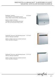
Montage des Schließkastens<br />
<strong>Schloss</strong>kasten (1) <strong>und</strong> Schließblech (2) müssen auf gleicher Ebene<br />
liegen. Beide Markierungskerben müssen übereinstimmen (Abb. 14).<br />
Zum Ausgleich der unterschiedlichen Falzhöhen wird das Schließblech<br />
(2) unterlegt. Hierzu dienen die Anschraubleiste (4) <strong>und</strong>/oder<br />
die Unterlagen (9). Sie sollten 1 mm höher als der Fensterfalz liegen.<br />
Falzhöhe 14 mm <strong>und</strong> größer<br />
1. Anschraubleiste (4) ggf. mit Unterlagen (9) mit 3 Schrauben<br />
5,5 x 60 mm festschrauben Schraublöcher (A) (Abb. 15).<br />
2. Durch das schräge Schraubenloch „C“ im gleichen Winkel schräg<br />
zur Wand vorbohren (s. Bohrtabelle) <strong>und</strong> weitere Schraube<br />
5,5 x 60 mm einschrauben (Abb. 16). Wenn Schrägverschraubung<br />
nicht möglich, kann bei Benutzung der Keilscheibe (6) in Schraubloch<br />
„C“ auch gerade verschraubt werden (nicht bei Holzfenstern).<br />
3. Haube vom Schließblech (2) abziehen, <strong>Fenstergriff</strong> auf Pos.<br />
„offen“ stellen, Schließblech (2) „R“ oder „L“ auswählen <strong>und</strong><br />
mit 3 Schrauben M6 x 16 mm festschrauben (Abb. 17).<br />
4. Schließfunktion prüfen, Riegel muss beim Einschließen frei<br />
laufen, ggf. Unterlagenaufbau (9) korrigieren.<br />
Falzhöhe von 0 –13 mm<br />
1. Schließblech (2) „R“ oder „L“ auswählen ggf. mit Unterlagen (9)<br />
mit 3 Schrauben 5,5 x 60 mm (Schraublöcher B) festschrauben<br />
(Abb. 18).<br />
2. Schließfunktion prüfen, Riegel muss beim Einschließen frei<br />
laufen, ggf. Unterlagenaufbau korrigieren.<br />
Endmontage <strong>Schloss</strong>kasten<br />
Hauben auf <strong>Schloss</strong>- <strong>und</strong> Schließkasten drücken <strong>und</strong> einrasten<br />
lassen (Abb. 20).<br />
VI. Bedienung<br />
Die normalen Funktionen des eingebauten Fensterbeschlages werden<br />
durch die <strong>FO</strong> <strong>400</strong> ausgeführt. Die zusätzliche Ver- <strong>und</strong> Entriegelung<br />
der Zusatzsicherung erfolgt hierbei automatisch.<br />
Hinweis:<br />
Auch in gekippter Fensterstellung Zylinder eindrücken<br />
(Kindersicherung <strong>und</strong> Durchgreifschutz).<br />
D Technische Änderungen vorbehalten. Für Irrtümer <strong>und</strong> Druckfehler keine Haftung. <strong>ABUS</strong> © 2006<br />
G Subject to technical alterations. No liability for mistakes and printing errors. <strong>ABUS</strong> © 2006<br />
G Fitting the lock case<br />
1. Adjust the existing window handle to the open position and unscrew<br />
the screws. Close window again with old pin and remove handle.<br />
2. Dismantle lock case (1) <strong>FO</strong> <strong>400</strong> (fig. 3): remove cover, unscrew screw.<br />
Take locking plate, locking bolt and turning sleeve from lock housing<br />
(careful, the loose drive pin can fall out).<br />
3. Screw on the base plate with enclosed countersunk screws<br />
M5 x 35 mm (fig. 4a). Check position with turning sleeve and<br />
inserted square pin (7 or 8) (fig. 4b).<br />
4. Define the length of the square pin:<br />
Measure the length of the square pin (7 or 8) on the unscrewed<br />
window handle (fig. 5). Insert the short square pin (7) with<br />
the long side into the turning sleeve. If it is not long enough,<br />
use the long square pin (8) and possibly shorten to the size “X”.<br />
5. Insert the turning sleeve and square pin into the base plate.<br />
Adjust the cams of the turning sleeve to the marking “R" or “L”<br />
(window opens to the right = “R“, to the left = “L“) (fig. 6).<br />
6. Test closing:<br />
Put the lock case (handle pointing downward) onto the base plate.<br />
Turn the handle 90° back and forwards (180° for turn-and-tilt<br />
windows). Take lock case off again. If lock moved stiffly, loosen<br />
countersunk screw M5 x 35mm and move base plate a little.<br />
Drilling the locking case side (frame) and defining the locking bolt<br />
adjusting size<br />
1. Put the two halves of the mounting plates 1 and 2 together (5) and<br />
line with screw-on strip (4) or shims (9) depending on the rebate<br />
height. Place the mounting plate on the base plate (fig. 7), with the<br />
stopper ridges on the window casement. For frame widths less than<br />
19 mm, break off the 2 mm thick stopper ridges (fig. 8 E) and place<br />
the mounting plate in position with the 1 mm stopper ridges (fig. 8).<br />
Read locking bolt size on the scale of the mounting plate (fig. 9)<br />
and make a note of the size.<br />
2. Pre-drill screw holes (fig. 10) (see drilling table). For rebate height<br />
14 mm and larger, 3 x hole A; for rebate height 0 to 13 mm:<br />
3 x hole B.<br />
3. Adjust the locking bolt according to the read size or max. 1 mm<br />
smaller (fig. 11a).<br />
4. Put the drive pin into the locking bolt hole “R“ or “L“<br />
(see point 5, Fitting the lock case) (fig. 11b).<br />
5. Put the locking bolt onto the turning sleeve and square pin (7 or 8).<br />
6. Put the U-locking plate with groove over the drive pin on the side<br />
onto the locking bolt (small bores at the top (fig. 12).<br />
7. Position the lock housing (handle pointing downwards) and screw<br />
tight with screw M6 x 25 mm (tapping screw) in the upper hole<br />
(fig. 13). If the locking bolt jams, unscrew the screw slightly<br />
(the locking bolt must turn freely). In the locked state, the window<br />
and lock are locked completely when the cylinder is pressed in.<br />
Fitting the locking case<br />
Lock case (1) and locking plate (2) must be on the same level.<br />
Both marking notches must match (fig. 14). The locking plate (2)<br />
is lined to compensate for the difference in rebate height, either with<br />
the screw-on strip (4) and/or the shims (9). They should be 1 mm<br />
higher than the window rebate.<br />
Rebate height 14 mm and more<br />
1. Screw the screw-on strip (4) tight, possibly with the shims (9),<br />
using 3 screws 5.5 x 60 mm, screw holes A (fig. 15).<br />
2. Drill through the slanting screw hole “C“ at the same angle<br />
at a slant to the wall (see drilling table) and screw in another screw<br />
5.5 x 60 mm (fig. 16). If it is not possible to screw in at a slant,<br />
screw in straight using the wedge washer (6) in screw hole “C“<br />
(not for wooden windows).<br />
3. Pull the cover from the locking plate (2), adjust the window handle<br />
to the “open“ position, select locking plate (2) “R“ or “L“ and<br />
screw tight with 3 screws M6 x 16 mm (fig. 17).<br />
4. Check locking function, locking bolt must run freely when locking,<br />
if necessary correct shim package.<br />
Rebate height 0 to 13 mm<br />
1. Select locking plate (2) “R“ or “L“, screw tight possibly with shims (9)<br />
using 3 screws 5.5 x 60 mm (screw holes B (fig. 18).<br />
2. Check locking function, locking bolt must run freely when locking,<br />
if necessary correct shim package.<br />
Pre-drill through the holes D of the lock body (see drilling table)<br />
and screw lock body tight using screws 5.5 x 60 mm.<br />
Press covers onto lock body and locking case so that they snap<br />
in (fig. 20).<br />
VI. Operation<br />
<strong>FO</strong> <strong>400</strong> performs the normal functions of the installed window<br />
hardware. The additional locking and unlocking of the additional<br />
security device functions automatically.<br />
www.abus.com<br />
390158 5/06