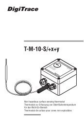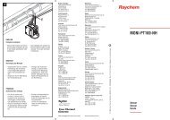
DigiTrace TCON-CSD/20
DigiTrace TCON-CSD/20
DigiTrace TCON-CSD/20

Create successful ePaper yourself
Turn your PDF publications into a flip-book with our unique Google optimized e-Paper software.
<strong>DigiTrace</strong> <strong>TCON</strong>-<strong>CSD</strong>/<strong>20</strong><br />
Digitaler Thermostat<br />
Digital Thermostat - Thermostat numérique<br />
B 70.1050.5.1<br />
Betriebsanleitung<br />
Operating Instructions - Notice de mise en service<br />
12.03/00433622
Funktionsübersicht
Inhalt<br />
1 Geräteausführung identifizieren . . . . . . . . . . . . . . . . . . . . . . . . . . . . . . . . . . . . . . . . . . . . 4<br />
2 Montage . . . . . . . . . . . . . . . . . . . . . . . . . . . . . . . . . . . . . . . . . . . . . . . . . . . . . . . . . . . . . . . . 5<br />
3 Elektrischer Anschluss . . . . . . . . . . . . . . . . . . . . . . . . . . . . . . . . . . . . . . . . . . . . . . . . . . . .6<br />
3.1 Installationshinweise . . . . . . . . . . . . . . . . . . . . . . . . . . . . . . . . . . . . . . . . . . . . . . . . . . . . . . . 6<br />
3.2 Anschlussplan . . . . . . . . . . . . . . . . . . . . . . . . . . . . . . . . . . . . . . . . . . . . . . . . . . . . . . . . . . . . 7<br />
Inhalt<br />
4 Gerät in Betrieb nehmen . . . . . . . . . . . . . . . . . . . . . . . . . . . . . . . . . . . . . . . . . . . . . . . . . . .8<br />
4.1 Anzeige- und Bedienelemente . . . . . . . . . . . . . . . . . . . . . . . . . . . . . . . . . . . . . . . . . . . . . . . . 8<br />
4.2 Gerätefunktionen einstellen (Parameterebene) . . . . . . . . . . . . . . . . . . . . . . . . . . . . . . . . . . . 9<br />
4.3 Bedienrechte vergeben (Freigabeebene) . . . . . . . . . . . . . . . . . . . . . . . . . . . . . . . . . . . . . . . 14<br />
5 Bedienen . . . . . . . . . . . . . . . . . . . . . . . . . . . . . . . . . . . . . . . . . . . . . . . . . . . . . . . . . . . . . . . 15<br />
6 Technische Daten . . . . . . . . . . . . . . . . . . . . . . . . . . . . . . . . . . . . . . . . . . . . . . . . . . . . . . . . 16<br />
7 Alarmmeldungen . . . . . . . . . . . . . . . . . . . . . . . . . . . . . . . . . . . . . . . . . . . . . . . . . . . . . . . .18<br />
1 Instrument identification . . . . . . . . . . . . . . . . . . . . . . . . . . . . . . . . . . . . . . . . . . . . . . . 2<br />
2 Assembling . . . . . . . . . . . . . . . . . . . . . . . . . . . . . . . . . . . . . . . . . . . . . . . . . . . . . . . . . . . . . . 3<br />
3 Electrical connection . . . . . . . . . . . . . . . . . . . . . . . . . . . . . . . . . . . . . . . . . . . . . . . . . . . . . . 4<br />
3.1 Installation notes . . . . . . . . . . . . . . . . . . . . . . . . . . . . . . . . . . . . . . . . . . . . . . . . . . . . . . . . . . 4<br />
3.2 Connection diagram . . . . . . . . . . . . . . . . . . . . . . . . . . . . . . . . . . . . . . . . . . . . . . . . . . . . . . . . 5
4 Commissioning the instrument . . . . . . . . . . . . . . . . . . . . . . . . . . . . . . . . . . . . . . . . . . . . . . 6<br />
4.1 Displays and controls . . . . . . . . . . . . . . . . . . . . . . . . . . . . . . . . . . . . . . . . . . . . . . . . . . . . . . . 6<br />
4.2 Setting the instrument functions (parameter level) . . . . . . . . . . . . . . . . . . . . . . . . . . . . . . . . . 7<br />
4.3 Allocating user rights (enabling level) . . . . . . . . . . . . . . . . . . . . . . . . . . . . . . . . . . . . . . . . . . 12<br />
5 Operation . . . . . . . . . . . . . . . . . . . . . . . . . . . . . . . . . . . . . . . . . . . . . . . . . . . . . . . . . . . . . . 13<br />
6 Technical data . . . . . . . . . . . . . . . . . . . . . . . . . . . . . . . . . . . . . . . . . . . . . . . . . . . . . . . . . . 14<br />
7 Alarm messages . . . . . . . . . . . . . . . . . . . . . . . . . . . . . . . . . . . . . . . . . . . . . . . . . . . . . . . . . 16<br />
1 Identification de l’appareil . . . . . . . . . . . . . . . . . . . . . . . . . . . . . . . . . . . . . . . . . . . . . . . . . 2<br />
Inhalt<br />
2 Montage . . . . . . . . . . . . . . . . . . . . . . . . . . . . . . . . . . . . . . . . . . . . . . . . . . . . . . . . . . . . . . . . 3<br />
3 Raccordement électrique . . . . . . . . . . . . . . . . . . . . . . . . . . . . . . . . . . . . . . . . . . . . . . . . . . 4<br />
3.1 Instructions à propos de l’installation . . . . . . . . . . . . . . . . . . . . . . . . . . . . . . . . . . . . . . . . . .4<br />
3.2 Schéma de raccordement . . . . . . . . . . . . . . . . . . . . . . . . . . . . . . . . . . . . . . . . . . . . . . . . . . .5<br />
4 Mise en service de l’appareil . . . . . . . . . . . . . . . . . . . . . . . . . . . . . . . . . . . . . . . . . . . . . . . . 6<br />
4.1 Affichage et commande . . . . . . . . . . . . . . . . . . . . . . . . . . . . . . . . . . . . . . . . . . . . . . . . . . . . . 6<br />
4.2 Réglage des fonctions de l’appareil (niveau "Paramétrage") . . . . . . . . . . . . . . . . . . . . . . . . . 7<br />
4.3 Attribution du code d’accès (Niveau "Déverrouillage") . . . . . . . . . . . . . . . . . . . . . . . . . . . . 12<br />
5 Commande . . . . . . . . . . . . . . . . . . . . . . . . . . . . . . . . . . . . . . . . . . . . . . . . . . . . . . . . . . . . . 13<br />
6 Données techniques . . . . . . . . . . . . . . . . . . . . . . . . . . . . . . . . . . . . . . . . . . . . . . . . . . . . . 14<br />
7 Messages d’erreur . . . . . . . . . . . . . . . . . . . . . . . . . . . . . . . . . . . . . . . . . . . . . . . . . . . . . . .16
1 Geräteausführung identifizieren<br />
Das Typenschild mit dem Bestellschlüssel ist auf der Seite des Gerätes aufgeklebt. Die angeschlossene Spannungsversorgung<br />
muss mit der auf dem Typenschild angegebenen Spannung identisch sein.<br />
1 Geräteausführung identifizieren 4<br />
erforderlichen Einstellungen sind in der vorliegenden Betriebsanleitung beschrieben. Sollten trotzdem bei<br />
der Inbetriebnahme Schwierigkeiten auftreten, bitten wir Sie, keine unzulässigen Manipulationen am Gerät<br />
vorzunehmen. Sie gefährden dadurch Ihren Garantieanspruch! Bitte setzen Sie sich mit der nächsten Niederlassung<br />
oder mit dem Stammhaus in Verbindung.<br />
H Alle<br />
Lesen Sie diese Betriebsanleitung, bevor Sie das Gerät in Betrieb nehmen. Bewahren Sie die Betriebsanleitung<br />
an einem für alle Benutzer jederzeit zugänglichen Platz auf. Bitte unterstützen Sie uns, diese Betriebsanleitung<br />
zu verbessern.<br />
Lieferumfang<br />
1 Betriebsanleitung
2 Montage<br />
Demontage<br />
°C<br />
(1) (2)<br />
90<br />
2 Montage 5<br />
55<br />
0<br />
≤ 75
3 Elektrischer Anschluss<br />
3.1 Installationshinweise<br />
3 Elektrischer Anschluss 6<br />
a Bei der Wahl des Leitungsmaterials, bei der Installation, bei der Absicherung und beim elektrischen Anschluss des<br />
Gerätes sind die Vorschriften der VDE 0100 „Bestimmungen über das Errichten von Starkstromanlagen mit Nennspannungen<br />
unter 1000 V“ oder die jeweiligen Landesvorschriften zu beachten.<br />
a Der elektrische Anschluss darf nur von Fachpersonal durchgeführt werden.<br />
a Die elektromagnetische Verträglichkeit entspricht den in den technischen Daten aufgeführten Normen und Vorschriften.<br />
a Das Gerät ist nicht für die Installation in explosionsgefährdeten Bereichen geeignet und muß in ein Brand- /Elektrisches<br />
Schutzgehäuse eingebaut werden.<br />
a Neben einer fehlerhaften Installation können auch falsch eingestellte Werte am Gerät (Sollwert,<br />
Daten der Parameterebene) den nachfolgenden Prozeß in seiner ordnungsgemäßen Funktion beeinträchtigen oder zu<br />
Beschädigungen führen. Es sollten daher immer vom Gerät unabhängige Sicherheitseinrichtungen, z. B. Überdruckventile<br />
oder Temperaturbegrenzer/-wächter vorhanden und die Einstellung nur dem Fachpersonal möglich sein (Parameter<br />
für die Bedienung sperren). Bitte in diesem Zusammenhang die entsprechenden Sicherheitsvorschriften beachten. Bei<br />
ungünstiger Verstellung der Parameter ist theoretisch eine instabile Regelung möglich. Der erreichte Istwert sollte daher<br />
auf seine Stabilität hin kontrolliert und Kenntnisse über die Regelstrecke gesammelt werden.<br />
a Der Lastkreis muss auf den maximalen Relaisstrom abgesichert sein, um im Fall eines dortigen Kurzschlusses ein Verschweißen<br />
der Ausgangsrelais zu verhindern.<br />
a Keine weiteren Verbraucher an die Schraubklemmen für die Spannungsversorgung des Gerätes anschließen.<br />
a Die äußere Absicherung der Spannungsversorgung sollte, abhängig vom Leitungsquerschnitt, einen Wert von 1A nicht<br />
unterschreiten. Das Gerät 2-polig vom Netz trennen, wenn bei Arbeiten spannungsführende Teile berührt werden können<br />
(z.B über einen separaten Netzschalter).<br />
a Spannungsversorgung Messeingang und Spannungsversorgung<br />
AC kurzschlussfest galvanisch voneinander getrennt
3.2 Anschlussplan<br />
Spannungsversorgung<br />
AC 230V +10/-15%<br />
N (L-)<br />
L1 (L+)<br />
3 Elektrischer Anschluss 7<br />
elektrische Anschluss<br />
darf nur von Fachpersonal<br />
durchgeführt werden!<br />
V Der<br />
Relaisausgang<br />
Messeingang<br />
Pt 100<br />
Pt 1000<br />
KTY2X-6<br />
5 4<br />
J<br />
Relaisausgang<br />
Wechsler (potenzialfrei)<br />
10A/250V AC<br />
3 (Öffner)<br />
2 (Schliesser)<br />
1 (Pol)
4 Gerät in Betrieb nehmen<br />
4.1 Anzeige- und Bedienelemente<br />
LC-Display 6 mm hohe dreistellige Neunsegmentanzeige und<br />
Symbole für Temperatureinheit<br />
4 Gerät in Betrieb nehmen 8<br />
LED K1 LED K1 leuchtet, wenn das Relais angezogen ist.<br />
LED K1 erlischt, wenn das Relais abfällt.<br />
Tasten Programmieren<br />
Wert vergrößern<br />
Bedienstatus in Freigabeebene wählen<br />
Wert verkleinern<br />
Bedienstatus in Freigabeebene wählen<br />
h Spannungsversorgung anlegen, alle Segmente leuchten zum Test zweimal auf (Segmenttest).<br />
Ist am Gerät alles korrekt angeschlossen, zeigt es die aktuelle Temperatur an (Temperaturanzeige).<br />
Erscheint eine Alarmmeldung, siehe Kapitel 7 „Alarmmeldungen“.<br />
Das Relais arbeitet je nach eingestellter Reglerart, siehe Kapitel 4.2 „Gerätefunktionen einstellen (Parameterebene)“.
4.2 Gerätefunktionen einstellen (Parameterebene)<br />
H Timeout:<br />
Wird 60 Sekunden lang keine Taste bedient, schaltet das Gerät automatisch in die Temperaturanzeige zurück,<br />
siehe Funktionsübersicht auf der ersten Innenseite.<br />
4 Gerät in Betrieb nehmen 9<br />
In der Parameterebene werden Gerätefunktionen und Werte eingestellt.<br />
h 3 Sekunden lang drücken und es erscheint abwechselnd .<br />
h Code 72 für den Zugang zur Parameterebene mit den Tasten und einstellen.<br />
Je länger die Taste gedrückt wird, desto schneller verändert sich der Wert.<br />
h Mit quittieren,<br />
Parametername und Wert erscheinen abwechselnd, z.B. .<br />
h Mit den Tasten und Wert im angegebenen Wertebereich einstellen.<br />
h Einstellungen mit quittieren.<br />
h Nächsten Parameter einstellen, siehe Funktionsübersicht auf der ersten Innenseite.
Regler<br />
Wertebereich<br />
von...werkseitig...bis<br />
Parameter Bedeutung<br />
4 Gerät in Betrieb nehmen 10<br />
Sollwert<br />
SP.L ... 3.0 ... SP.H<br />
Auf diese Temperatur wird geregelt.<br />
Hysterese 0.2 ... 1.0 ... 99.9 K/°F<br />
T/°C Kühlen T/°C Heizen<br />
SP = 70 °C<br />
HYS<br />
69 °C<br />
9<br />
HYS<br />
SP = 8 °C<br />
t<br />
t<br />
Relais<br />
angezogen<br />
Relais<br />
angezogen<br />
abgefallen<br />
abgefallen<br />
t<br />
t<br />
-350 ... -40 ... 999°C/°F<br />
untere Sollwertgrenze<br />
Bis zu dieser unteren Grenze kann SP eingestellt werden.<br />
-350 ... 500 ... 999°C/°F<br />
obere Sollwertgrenze<br />
Bis zu dieser oberen Grenze kann SP eingestellt werden.<br />
,<br />
Reglerart<br />
: Kühlregler<br />
: Heizregler
Wertebereich<br />
von...werkseitig...bis<br />
Parameter Bedeutung<br />
0...0 ... 60min<br />
Einschaltverzögerungszeit nach Netz-Ein<br />
Zum zeitversetzten Einschalten mehrerer Aggregate einer Anlage.<br />
0 ... 0 ... 999 s<br />
4 Gerät in Betrieb nehmen 11<br />
Minimale Einschaltdauer<br />
Hier kann eingestellt werden, wie lange z. B. das Aggregat mindestens eingeschaltet<br />
bleiben muss. Diese Angaben sind abhängig vom verwendeten<br />
Heiz- oder Kühlgerät (Herstellerangaben beachten).<br />
0 ... 0 ... 999 s<br />
Minimale Ausschaltdauer<br />
Hier kann eingestellt werden, wie lange z. B. das Aggregat mindestens ausgeschaltet<br />
bleiben muss. Diese Angaben sind abhängig vom verwendeten<br />
Heiz- oder Kühlgerät (Herstellerangaben beachten).<br />
Alarme<br />
-300 ... 1°C ... 900°C/°F<br />
untere Alarmgrenztemperatur<br />
Sobald der Istwert diese Grenze unterschreitet, wird die Alarmmeldung<br />
in der Anzeige ausgegeben, siehe Kapitel 7 „Alarmmeldungen“.<br />
-300 ... <strong>20</strong>0 ... 900°C/°F<br />
obere Alarmgrenztemperatur<br />
Sobald der Istwert diese Grenze überschreitet, wird die Alarmmeldung<br />
in der Anzeige ausgegeben, siehe Kapitel 7 „Alarmmeldungen“.<br />
0 ... 0 ... 60 min<br />
Alarmunterdrückungszeit<br />
Für diese Zeit wird ein Alarm von oder nicht im Display angezeigt.<br />
Ist ein Alarm länger als vorhanden, wird er angezeigt.<br />
0, 1<br />
Verhalten bei Messbereichsüber- oder -unterschreitung<br />
0: Relais fällt ab<br />
1: Relais zieht an
Wertebereich<br />
von...werkseitig...bis<br />
Parameter Bedeutung<br />
Eingang<br />
Pt 100: P.1h<br />
Pt 1000: P.1t<br />
KTY2X-6: PtC<br />
Messwertgeber<br />
Angeschlossener Messwertgeber in Zweileiterschaltung<br />
4 Gerät in Betrieb nehmen 12<br />
-99,9 ... 0,0 ... 99,9 K/°F<br />
Offset Temperatur<br />
Temperatur Offset in K oder °F<br />
0,0 ... 0,0 ... 99,9 in Ω<br />
Leitungsabgleichwiderstand<br />
Dieser Wert dient zur Kompensation des Widerstands der Fühlerleitung und<br />
ist abhängig von der Leitungslänge.<br />
Für eine bestmögliche Temperaturmessung muss hier der ohmsche Widerstand<br />
der Fühlerleitung bei kurzgeschlossenem Fühler eingegeben werden.<br />
°C oder °F<br />
Gesamtwiderstand im Messbereich Pt100: 3<strong>20</strong> Ω und<br />
Pt1000/KTY2x-6: 3<strong>20</strong>0 Ω<br />
Einheit<br />
für die angezeigte Temperatur<br />
A<br />
Nur der Messwert wird bei der Umstellung in °F entsprechend<br />
umgerechnet. Alle anderen Temperaturgrößen z. B SP bleiben in<br />
ihrem Wert erhalten.
Wertebereich<br />
von...werkseitig...bis<br />
Parameter Bedeutung<br />
0,1 ... 0,8 ... 99,9 s<br />
4 Gerät in Betrieb nehmen 13<br />
Filterzeitkonstante<br />
Zur Anpassung des digitalen Eingangsfilters (0,0Sekunden = Filter aus).<br />
Bei einem Signalsprung werden nach der Filterzeitkonstante 63% der Änderungen<br />
erfasst.<br />
Werte zwischen 0,1 und 0,7 werden als 0,8 interpretiert (Abtastzeit).<br />
Wenn die Filterzeitkonstante groß ist:<br />
-hohe Dämpfung von Störsignalen<br />
-langsame Reaktion der Istwertanzeige auf Istwertänderungen<br />
> 3 sec zurück zum 1. Parameter SP der Parameterebene.<br />
H Mit
4.3 Bedienrechte vergeben (Freigabeebene)<br />
Die Einstellung in der Freigabeebene legt Bedienrechte fest, die darüber entscheiden, ob ein Parameter in der Bedienebene<br />
erscheint, editiert werden kann oder gar nicht erscheint.<br />
h 3 Sekunden lang drücken und erscheint.<br />
4 Gerät in Betrieb nehmen 14<br />
h Code 82 für den Zugang zur Freigabeebene mit den Tasten und einstellen.<br />
h Mit quittieren<br />
Parameter und Bedienrecht blinken abwechselnd z. B. .<br />
h Mit den Tasten und Bedienrecht , oder einstellen.<br />
Bedienrecht Anzeige werkseitig<br />
Parameter ist einstellbar<br />
Parameter erscheint -<br />
Parameter erscheint nicht alle anderen Parameter<br />
h Einstellungen mit quittieren.<br />
h Nächsten Parameter einstellen, siehe Funktionsübersicht auf der ersten Innenseite.
5 Bedienen<br />
Solltemperatur und weitere Parameter ändern<br />
Temperaturanzeige<br />
Softwareversion anzeigen<br />
P +<br />
(gleichzeitig)<br />
5 Bedienen 15<br />
oder Timeout (nach ca. 30 Sekunden)<br />
(Beispiel)<br />
P<br />
Solltemperatur<br />
P<br />
P<br />
Weitere Parameter anzeigen<br />
(je nach eingestelltem Bedienrecht<br />
in der Freigabeebene)
6 Technische Daten<br />
Messeingang<br />
Bezeichnung Messbereich Genauigkeit Messbereichsüber- und<br />
-unterschreitung<br />
6 Technische Daten 16<br />
Pt 100 DIN/EN 60751 -<strong>20</strong>0 … +500°C 0,1% wird erkannt<br />
Pt 1000 DIN/EN 60 751 -<strong>20</strong>0 … +500°C 0,1% wird erkannt<br />
KTY2X-6 -50 ... 150 °C 1% wird erkannt<br />
Temperatureinfluss ≤ 100 ppm/K vom Messbereich<br />
Abtastzeit 250 ms, Auflösung > 14Bit<br />
Eingangsfilter digitales Filter 1. Ordnung; Filterkonstante einstellbar von 0 … 99,9s<br />
über den Parameter Leitungsabgleichwiderstand einstellbar<br />
Leitungsabgleich 1<br />
über den Parameter Temperatur Offset einstellbar<br />
Temperatur Offset 1<br />
Besonderheiten Temperaturanzeige °C, auf °F (Fahrenheit) umstellbar<br />
1. siehe Kapitel 4.2 „Gerätefunktionen einstellen“ (Parameterebene)<br />
Umwelteinflüsse<br />
Umgebungstemperaturbereich 0 ... +55°C, bei Dicht-an-dicht-Montage: 0 ... +40°C<br />
Lagertemperaturbereich -40 ... +70°C<br />
Klimafestigkeit ≤ 75% rel. Feuchte ohne Betauung<br />
Ausgang<br />
Relais (Wechselkontakt) 150.000 Schaltungen bei AC 10A/250V 50Hz ohmscher Last<br />
800.000 Schaltungen bei AC 3A/250V 50Hz ohmscher Last
Spannungsversorgung<br />
Spannungsversorgung AC 230V +10/-15%<br />
Leistungsaufnahme < 2VA<br />
Gehäuse<br />
Material Polycarbonat<br />
Montage Hutschiene 35mm x 7,5mm nach EN 50022<br />
Einbaulage beliebig<br />
Gewicht ca. 110g<br />
Schutzart IP <strong>20</strong><br />
Brennbarkeitsklasse UL 94 V0<br />
6 Technische Daten 17<br />
Elektrische Daten<br />
Datensicherung EEPROM<br />
Anschlussart Schraubklemmen für Drahtquerschnitte bis max. 2,5 mm2 EN 61326<br />
Klasse B<br />
Industrieanforderung<br />
Elektromagnetische Verträglichkeit<br />
Störaussendung<br />
Störfestigkeit<br />
Elektrische Sicherheit DIN EN 61 010, Teil 1, Überspannungskategorie III, Verschmutzungsgrad 2
7 Alarmmeldungen<br />
In der Temperaturanzeige können folgende Alarmmeldungen angezeigt werden:<br />
Fehleranzeige Ursache Abhilfe<br />
- Sensor und Anschlussleitung auf Beschädigung<br />
oder Kurzschluss überprüfen<br />
Anzeigeüberlauf<br />
Der Messwert ist zu groß und<br />
liegt außerhalb des Messbereichs.<br />
7 Alarmmeldungen 18<br />
- Überprüfen, ob der richtige Sensor eingestellt<br />
oder angeschlossen ist<br />
v Kapitel 4 „Gerät in Betrieb nehmen“<br />
H<br />
Diese Meldungen werden nur in der<br />
Temperaturanzeige ausgegeben.<br />
Anzeigeunterlauf<br />
Der Messwert ist zu klein und<br />
liegt außerhalb des Messbereichs.<br />
h Einschaltverzögerung abbrechen<br />
mit +<br />
Zeit für Einschaltverzögerung<br />
nach Netz-Ein läuft ab.<br />
Bei Anzeigeüber- oder -unterlauf<br />
wird die Einschaltverzögerung<br />
verlassen.<br />
untere Alarmgrenztemperatur<br />
unterschritten<br />
h Je nach eingestellter Reglerart überprüfen, ob<br />
das Heiz- oder Kühlaggregat noch einwandfrei<br />
funktioniert.<br />
h Überprüfen, ob evtl. eingebaute Relaisabsicherung<br />
noch in Ordnung ist.<br />
obere Alarmgrenztemperatur<br />
überschritten<br />
Der Alarm verschwindet, sobald die Temperatur die AL-Grenzen<br />
um die Hysterese über- bzw. unterschreitet.
INSTALL-100 R0-03/05
<strong>DigiTrace</strong> <strong>TCON</strong>-<strong>CSD</strong>/<strong>20</strong><br />
Digital Thermostat<br />
B 70.1050.5.1<br />
Operating Instructions<br />
12.03
Overview of operation<br />
Alternating display<br />
> 3 seconds<br />
P<br />
Temperature display<br />
30 seconds time-out<br />
or P + (simultaneously)<br />
Enter code<br />
increase<br />
increase<br />
decrease<br />
decrease<br />
P<br />
P<br />
or 30 seconds<br />
P<br />
time-out<br />
P<br />
Enabling level<br />
Define parameters which can be<br />
displayed or edited at the<br />
operating level.<br />
Parameter level<br />
Factory-set parameters can be<br />
modified here.<br />
Operating level<br />
Parameters that have been<br />
selected at the enabling level.<br />
Alternating display Alternating display Alternating display<br />
increase<br />
increase<br />
editable<br />
decrease<br />
decrease<br />
show<br />
do not<br />
enable<br />
P<br />
P P<br />
P<br />
P<br />
additional parameters<br />
additional parameters …<br />
additional parameters<br />
last parameter<br />
… from the<br />
enabling level<br />
xxx<br />
60 seconds time-out or P + (simultaneously)
Contents<br />
1 Instrument identification . . . . . . . . . . . . . . . . . . . . . . . . . . . . . . . . . . . . . . . . . . . . . . . 2<br />
2 Assembling . . . . . . . . . . . . . . . . . . . . . . . . . . . . . . . . . . . . . . . . . . . . . . . . . . . . . . . . . . . . . . 3<br />
3 Electrical connection . . . . . . . . . . . . . . . . . . . . . . . . . . . . . . . . . . . . . . . . . . . . . . . . . . . . . . 4<br />
3.1 Installation notes . . . . . . . . . . . . . . . . . . . . . . . . . . . . . . . . . . . . . . . . . . . . . . . . . . . . . . . . . . 4<br />
3.2 Connection diagram . . . . . . . . . . . . . . . . . . . . . . . . . . . . . . . . . . . . . . . . . . . . . . . . . . . . . . . . 5<br />
Contents<br />
4 Commissioning the instrument . . . . . . . . . . . . . . . . . . . . . . . . . . . . . . . . . . . . . . . . . . . . . . 6<br />
4.1 Displays and controls . . . . . . . . . . . . . . . . . . . . . . . . . . . . . . . . . . . . . . . . . . . . . . . . . . . . . . . 6<br />
4.2 Setting the instrument functions (parameter level) . . . . . . . . . . . . . . . . . . . . . . . . . . . . . . . . . 7<br />
4.3 Allocating user rights (enabling level) . . . . . . . . . . . . . . . . . . . . . . . . . . . . . . . . . . . . . . . . . . 12<br />
5 Operation . . . . . . . . . . . . . . . . . . . . . . . . . . . . . . . . . . . . . . . . . . . . . . . . . . . . . . . . . . . . . . 13<br />
6 Technical data . . . . . . . . . . . . . . . . . . . . . . . . . . . . . . . . . . . . . . . . . . . . . . . . . . . . . . . . . . 14<br />
7 Alarm messages . . . . . . . . . . . . . . . . . . . . . . . . . . . . . . . . . . . . . . . . . . . . . . . . . . . . . . . . . 16
1 Instrument identification<br />
The nameplate with the order code is affixed to the instrument side. The supply that is connected must correspond to<br />
the voltage specified on the nameplate.<br />
1 Instrument identification 2<br />
necessary settings are described in these Operation Instructions. However, if any difficulties should still<br />
arise during start-up, you are asked not to carry out any unauthorized manipulations on the unit. This could<br />
endanger your rights under the instrument warranty! Please contact the nearest subsidiary or the head office<br />
in such a case.<br />
H All<br />
Please read these operating instructions before commissioning the instrument. Keep the manual in a place<br />
that is accessible to all users at all times. Please assist us to improve these operating instructions, where necessary.<br />
Included in delivery:<br />
1 Operating Instructions
2 Assembling<br />
Disassembling<br />
°C<br />
2 Assembling 3<br />
(1) (2)<br />
90<br />
55<br />
0<br />
≤ 75
3 Electrical connection<br />
3.1 Installation notes<br />
3 Electrical connection 4<br />
a The choice of cable, the installation, the fusing and the electrical connection must conform to the requirements<br />
of VDE 0100 “Regulations on the Installation of Power Circuits with nominal voltages below 1000 V” or the<br />
appropriate local regulations.<br />
a The electrical connection must only be carried out by qualified personnel.<br />
a The electromagnetic compatibility conforms to the standards and regulations listed under Technical data.<br />
a The instrument is not suitable for installation in areas with an explosion hazard.<br />
a Apart from faulty installation, incorrect settings on the thermostat (setpoint, parameter level data) may also<br />
affect the proper functioning of controlled processes or lead to damage. Provision should therefore always be<br />
made for safety devices that are independent of the thermostat, e. g. overpressure valves or temperature<br />
limiters/monitors. Adjustment must be restricted to specialist personnel (lock parameters for operation).<br />
Please observe the corresponding safety regulations in this matter. Unfavorable parameter adjustment may<br />
result in unstable control. The process value obtained should therefore be monitored for its stability and<br />
knowledge about the process should be obtained.<br />
a The load circuit must be fused for the maximum relay current in order to prevent welding of the output relay<br />
contacts in the event of a short circuit.<br />
a Do not connect any additional loads to the supply terminals of the instrument.<br />
a The external fuse of the supply should not be rated below 1A, depending on the conductor cross-section. If<br />
contact with live components is possible while working on the thermostat, it must be disconnected on both<br />
poles from the supply.<br />
a Supply Measurement input and supply<br />
AC short-circuit-proof electrically isolated from each other
3.2 Connection diagram<br />
Supply voltage<br />
230V AC +10/-15%<br />
N (L-)<br />
L1 (L+)<br />
electrical connection<br />
must only be carried out by<br />
qualified personnel!<br />
V The<br />
3 Electrical connection 5<br />
Relay<br />
output<br />
Measurement input<br />
Pt 100<br />
Pt 1000<br />
KTY2X-6<br />
5 4<br />
J<br />
Relay output<br />
changeover contact<br />
(floating)<br />
10A 250V AC<br />
3 (break contact)<br />
2 (make contact)<br />
1 (common)
4 Commissioning the instrument<br />
4.1 Displays and controls<br />
4 Commissioning the instrument 6<br />
LC display 3-digit 9-segment display, 6 mm high, with symbols<br />
for the temperature unit<br />
LED K1 LED K1 comes on when relay is energized.<br />
LED K1 goes out when relay is de-energized.<br />
Keys programming<br />
increase value<br />
select operational status at enabling level<br />
decrease value<br />
select operational status at enabling level<br />
h When connected to the supply, all segments light up twice as a test (segment test).<br />
When everything is connected up correctly on the instrument, the present temperature is shown (temperature<br />
display).<br />
If an alarm message appears, see Chapter 7 “Alarm messages”<br />
The relay operates according to the controller type that was set, see Chapter 4.2 “Setting the instrument functions<br />
(parameter level)”.
4.2 Setting the instrument functions (parameter level)<br />
H Time-out:<br />
If no key is pressed for 60 seconds, the instrument automatically switches back to temperature display, see<br />
Overview of operation on the first inside page.<br />
4 Commissioning the instrument 7<br />
The instrument functions and values are set at the parameter level.<br />
h Press for 3 seconds and will appear alternately.<br />
h Set code 72 for accessing the parameter level by using the and keys.<br />
The longer the key is pressed, the faster the value changes.<br />
h Acknowledge with ,<br />
parameter name and value appear alternately, e.g.<br />
h Set value within the specified value range by using the and keys.<br />
h Acknowledge settings with<br />
h Set next parameter, see Overview of operation on the first inside page.
Controller<br />
Value range<br />
from...factory-set...to<br />
Parameter Meaning<br />
4 Commissioning the instrument 8<br />
Setpoint<br />
SP.L ... 3.0 ... SP.H<br />
The target temperature<br />
Hysteresis 0.2 ... 1.0 ... 99.9 °C/°F<br />
T/°C Cooling<br />
T/°C Heating<br />
SP = 70 °C<br />
HYS<br />
69 °C<br />
9<br />
HYS<br />
SP = 8 °C<br />
t<br />
t<br />
Relay<br />
energized<br />
Relay<br />
energized<br />
de-energized<br />
de-energized<br />
t<br />
t<br />
-350 ... -40 ... 999°C/°F<br />
Low setpoint limit<br />
The lower limit for setpoint selection<br />
-350 ... 500 ... 999°C/°F<br />
High setpoint limit<br />
The upper limit for setpoint selection<br />
,<br />
Controller type<br />
: cooling controller<br />
: heating controller
Value range<br />
from...factory-set...to<br />
Parameter Meaning<br />
0...0 ... 60min<br />
Switch-on delay after power ON<br />
for staggered switch-on of several equipment units<br />
4 Commissioning the instrument 9<br />
0 ... 0 ... 999 sec<br />
Minimum ON time<br />
Here you can set the minimum time for which the equipment unit, for<br />
example, has to remain switched on. These values depend on the heating<br />
or cooling unit being used (observe manufacturer’s specifications).<br />
0 ... 0 ... 999 sec<br />
Minimum OFF time<br />
Here you can set the minimum time for which the equipment unit, for<br />
example, has to remain switched off. These values depend on the heating<br />
or cooling unit being used (observe manufacturer’s specifications).<br />
Alarms<br />
-300 ... 1°C ... 900°C/°F<br />
Low alarm limit temperature<br />
As soon as the process value falls below this limit, the alarm message<br />
is displayed, see Chapter 7 “Alarm messages”.<br />
-300 ... <strong>20</strong>0 ... 900°C/°F<br />
High alarm limit temperature<br />
As soon as the process value goes above this limit, the alarm message<br />
is displayed, see Chapter 7 “Alarm message”.<br />
0 ... 0 ... 60 min<br />
Alarm suppression time<br />
The alarm or is not displayed until this time has elapsed. If an<br />
alarm is present for longer than , then it will be displayed.<br />
0. 1<br />
Response to over/underrange<br />
0: relay de-energized<br />
1: relay energized
Value range<br />
from...factory-set...to<br />
Parameter Meaning<br />
Input<br />
4 Commissioning the instrument 10<br />
Pt 100: P.1h<br />
Pt 1000: P.1t<br />
Sensor<br />
Sensor connected in 2-wire circuit<br />
KTY2X-6: PtC<br />
-99.9 ... 0.0 ... 99.9 °C/<br />
°F<br />
Temperature offset<br />
Temperature offset in °C or °F<br />
0.0 ... 0.0 ... 99.9 in Ω<br />
Lead compensation resistance<br />
This value is used for compensating the resistance of the probe lead and<br />
depends on the lead length.<br />
For best temperature measurement results, the resistance value of the probe<br />
lead (with shorted probe) has to be entered here.<br />
Total resistance in the Pt100 range: 3<strong>20</strong> Ω and<br />
Pt1000/KTY2x-6: 3<strong>20</strong>0 Ω<br />
°C or °F<br />
Unit<br />
for the displayed temperature<br />
Only the measured value is converted accordingly when changing<br />
over to °F. All other temperature variables, e. g. SP, will retain their<br />
values.<br />
A
Value range<br />
from...factory-set...to<br />
Parameter Meaning<br />
0.1 ... 0.8 ... 99.9 sec<br />
4 Commissioning the instrument 11<br />
Filter time constant<br />
For adapting the digital input filter (0.0seconds = filter off).<br />
With a signal step, 63% of the changes are registered after the filter time<br />
constant has elapsed.<br />
Values between 0.1 and 0.7 are interpreted as 0.8 (sampling time).<br />
If the filter time constant is too long:<br />
- high damping of interference signals<br />
- slow reaction of the process value display to process value changes<br />
to the first parameter SP of the parameter level by pressing > 3 sec.<br />
H Return
4.3 Allocating user rights (enabling level)<br />
The setting at the enabling level defines user rights which determine whether a parameter is shown at the operating<br />
level, can be edited or is not shown at all.<br />
h Press for 3 seconds and appears<br />
4 Commissioning the instrument 12<br />
h Set code 82 for access to the enabling level by pressing and<br />
h Acknowledge with<br />
Parameter and User rights blink alternately e. g.<br />
h Use the and keys to set user rights to , or<br />
User rights Display factory-set<br />
Parameter can be edited<br />
Parameter is shown -<br />
Parameter is not shown all other parameters<br />
h Acknowledge settings with .<br />
h Set next parameter, see Overview of operation on the first inside page.
5 Operation<br />
Alter target temperature and further parameters<br />
Temperature display<br />
Display software version<br />
P +<br />
(simultaneously)<br />
(Example)<br />
5 Operation 13<br />
or time-out (after about 30 seconds)<br />
P<br />
Target temperature<br />
P<br />
P<br />
Display further parameters<br />
(according to the user rights<br />
selected at the enabling level)
6 Technical data<br />
Measurement input<br />
Designation Range Accuracy Overrange/underrange<br />
Pt100 EN 60 751 -<strong>20</strong>0 to +500°C 0.1% is recognized<br />
Pt1000 EN 60 751 -<strong>20</strong>0 to +500°C 0.1% is recognized<br />
KTY2X-6 -50 to 150 °C 1% is recognized<br />
6 Technical data 14<br />
Temperature error ≤ 100 ppm per °C of range<br />
Sampling time 250 msec, resolution > 14bit<br />
Input filter 1st order digital filter; filter constant adjustable from 0 — 99.9sec<br />
adjustable via the parameter Lead compensation resistance<br />
Lead compensation 1<br />
adjustable via the parameter Temperature offset<br />
Temperature offset 1<br />
Features temperature display °C, can be changed over to °F (Fahrenheit)<br />
1. see Chapter 4.2 “Setting the instrument functions” (parameter level)<br />
Environmental influences<br />
Ambient temperature range 0 to +55°C, for side-by-side mounting: 0 to +40°C<br />
Storage temperature range -40 to +70°C<br />
Climatic conditions ≤ 75% rel. humidity, no condensation<br />
Output<br />
Relay (changeover contact) 150,000 operations at 10A 250V AC 50Hz resistive load<br />
800,000 operations at 3A 250V AC 50Hz resistive load
6 Technical data 15<br />
Supply<br />
Supply voltage 230V AC +10/-15%<br />
Power consumption < 2VA<br />
Housing<br />
Material polycarbonate<br />
Mounting 35mm x 7.5mm DIN rail to EN 50 022<br />
Operating position unrestricted<br />
Weight approx. 110g<br />
Protection IP<strong>20</strong><br />
Flammability class UL 94 V0<br />
Electrical data<br />
Data backup EEPROM<br />
Connection screw terminals for wire cross-sections up to 2.5 mm2 max.<br />
Electromagnetic compatibility EN 61 326<br />
- interference emission<br />
Class B<br />
- immunity to interference<br />
to industrial requirements<br />
Electrical safety EN 61 010, Part 1, overvoltage category III, pollution degree 2
7 Alarm messages<br />
The following alarm messages can be shown in the temperature display:<br />
Error message Cause Elimination<br />
- Check sensor and connecting cable for damage<br />
or short circuit.<br />
Display overrun<br />
The measured value is too large<br />
and outside the range.<br />
- Check whether the correct sensor has been set or<br />
connected.<br />
7 Alarm messages 16<br />
v Chapter 4 “Commissioning the instrument”<br />
H These messages are only output<br />
to the temperature display.<br />
Display underrun<br />
The measured value is too small<br />
and outside the range.<br />
h Cancel switch-on delay<br />
with +<br />
Time for switch-on delay after<br />
power ON has elapsed.<br />
With display over/underrun, the<br />
switch-on delay becomes<br />
ineffective.<br />
Value has fallen below the low<br />
alarm limit temperature<br />
ProcVal<br />
h Depending on the controller type that was set,<br />
check whether the heating or cooling unit<br />
functions faultlessly.<br />
h Check whether the installed relay fuse is still in<br />
good working order.<br />
ProcVal<br />
Value has gone above the high<br />
alarm limit temperature<br />
ProcVal<br />
The alarm disappears as soon as the temperature goes above<br />
or below the AL limits by the amount of the hysteresis.
INSTALL-100 R0-03/05
<strong>DigiTrace</strong> <strong>TCON</strong>-<strong>CSD</strong>/<strong>20</strong><br />
Thermostat numérique<br />
B 70.1050.5.1<br />
Notice de mise en service<br />
12.03
Aperçu des fonctions<br />
L’affichage change<br />
> 3 secondes<br />
P<br />
Affichage de la température<br />
Incrémenter<br />
30 secondes Timeout<br />
ou P + (simultanément)<br />
Saisir le code<br />
Incrémenter<br />
Décrémenter<br />
Décrémenter<br />
P<br />
P<br />
ou 30 secondes Timeout<br />
P P<br />
Niveau “Déverrouillage”<br />
Définir les paramètres qui peuvent<br />
être affichés au niveau “Utilisateur”<br />
ou qui peuvent être édités.<br />
Niveau “Paramétrage”<br />
Les paramètres préréglés en usine<br />
peuvent être modifiés ici.<br />
Niveau “Utilisateur”<br />
Paramètres sélectionnés au<br />
niveau “Déverrouillage”<br />
L’affichage change L’affichage change L’affichage change<br />
Incrémenter<br />
Incrémenter<br />
Peut être<br />
édité<br />
Afficher<br />
Ne pas<br />
déverrouiller<br />
Décrémenter<br />
Décrémenter<br />
P<br />
P P<br />
P<br />
P<br />
Autres paramètres<br />
Autres paramètres<br />
Autres paramètres<br />
Dernier paramètre<br />
… Provenant du niveau<br />
“Déverrouillage”<br />
xxx<br />
60 secondes Timeout ou P + (simultanément)
Sommaire<br />
1 paramètres . . . . . . . . . . . . . . . . . . . . . . . . . . . . . . . . . . . . . . . . . . . . . . . . . . . . . . . . . . . . . 2<br />
2 Montage . . . . . . . . . . . . . . . . . . . . . . . . . . . . . . . . . . . . . . . . . . . . . . . . . . . . . . . . . . . . . . . . 3<br />
3 Raccordement électrique . . . . . . . . . . . . . . . . . . . . . . . . . . . . . . . . . . . . . . . . . . . . . . . . . . 4<br />
3.1 Instructions à propos de l’installation . . . . . . . . . . . . . . . . . . . . . . . . . . . . . . . . . . . . . . . . . .4<br />
3.2 Schéma de raccordement . . . . . . . . . . . . . . . . . . . . . . . . . . . . . . . . . . . . . . . . . . . . . . . . . . .5<br />
Sommaire<br />
4 Mise en service de l’appareil . . . . . . . . . . . . . . . . . . . . . . . . . . . . . . . . . . . . . . . . . . . . . . . . 6<br />
4.1 Affichage et commande . . . . . . . . . . . . . . . . . . . . . . . . . . . . . . . . . . . . . . . . . . . . . . . . . . . . . 6<br />
4.2 Réglage des fonctions de l’appareil (Niveau "Paramétrage") . . . . . . . . . . . . . . . . . . . . . . . . 7<br />
4.3 Attribution du code d’accès (Niveau "Déverrouillage"). . . . . . . . . . . . . . . . . . . . . . . . . . . . . 12<br />
5 Commande . . . . . . . . . . . . . . . . . . . . . . . . . . . . . . . . . . . . . . . . . . . . . . . . . . . . . . . . . . . . . 13<br />
6 Données techniques . . . . . . . . . . . . . . . . . . . . . . . . . . . . . . . . . . . . . . . . . . . . . . . . . . . . . . 14<br />
7 Messages d’erreur . . . . . . . . . . . . . . . . . . . . . . . . . . . . . . . . . . . . . . . . . . . . . . . . . . . . . . .16
1 Identification de l’appareil<br />
La plaque signalétique est collée sur la partie supérieure de l’appareil. La tension appliquée doit correspondre à celle<br />
indiquée sur la plaque signalétique.<br />
1 Identification de l’appareil 2<br />
les réglages et toutes les interventions éventuellement nécessaires sont décrits dans cette notice. Cependant,<br />
si vous rencontrez des difficultés lors de la mise en service de cet appareil, ne procédez en aucun<br />
cas à des manipulations inadaptées qui pourraient compromettre votre recours en garantie mais prenez contact<br />
avec nos services.<br />
H Tous<br />
Veuillez lire attentivement cette notice avant de procéder à la mise en service de l’appareil et conservez la à<br />
un endroit accessible à tous les utilisateurs.<br />
Livraison<br />
1 notice de mise en service
2 Montage<br />
Démontage<br />
°C<br />
(1) (2)<br />
90<br />
2 Montage 3<br />
55<br />
0<br />
≤ 75
3 Raccordement électrique<br />
3.1 Instructions à propos de l’installation<br />
3 Raccordement électrique 4<br />
a Veuillez respecter la réglementation en vigueur aussi bien pour le choix du matériel des lignes, pour l’installation,<br />
que pour le raccordement électrique de l’appareil.<br />
a Le raccordement électrique ne doit être effectué que par du personnel qualifié.<br />
a La compatibilité électromagnétique correspond aux normes et prescriptions mentionnés dans les données<br />
techniques.<br />
a Le thermostat n’est pas adapté pour être utilisé dans des atmosphères explosibles.<br />
a Non seulement une installation défectueuse mais également des valeurs mal réglées sur l’appareil (consignes,<br />
données de paramétrage et de configuration, modifications effectuées à l’intérieur de l’appareil) peuvent altérer<br />
le bon fonctionnement du process qui suit ou le détruire. C’est pourquoi, il doit toujours y avoir des dispositifs<br />
de sécurité indépendants de l’appareil) (soupapes de surpression ou limiteur/contrôleur de température par<br />
exemple) et le réglage ne doit être effectué que par du personnel qualifié. Nous vous prions de respecter les<br />
règles de sécurité correspondantes. L’autooptimisation ne permet pas de contrôler tous les systèmes asservis<br />
imaginables, un paramétrage instable est donc théoriquement possible. C’est pourquoi, il faut contrôler la stabilité<br />
de la valeur réelle atteinte.<br />
a En cas de court-circuit externe dans la charge, pour empêcher un soudage des relais de sortie, le circuit de<br />
charge doit être protégé par un fusible calibré au courant maximal du relais<br />
a Ne raccorder aucun autre récepteur aux bornes de l’alimentation de l’appareil<br />
a Le fusible externe de l’alimentation, dépendant de la section de fil, ne doit pas dépasser la valeur de 1 A.<br />
Séparer le thermostat 2 broches de l’alimentation, lorsque des pièces sous tension peuvent être touchées au<br />
cours de travaux.<br />
a Alimentation Entrée de mesure et tension d’alimentation<br />
AC Insensible au court-circuit Séparée galvaniquement l’une de l’autre
3.2 Schéma de raccordement<br />
Alimentation<br />
230V AC +10/-15%<br />
N (L-)<br />
L1 (L+)<br />
3 Raccordement électrique 5<br />
raccordement électrique<br />
ne doit être effectué que par<br />
du personnel qualifié !<br />
V Le<br />
Sortie<br />
relais-<br />
Entrée de mesure<br />
Pt 100<br />
Pt 1000<br />
KTY2X-6<br />
5 4<br />
<br />
Sortie relais<br />
inverseur (libre de<br />
potentiel)<br />
10A/250V AC<br />
3 (à ouverture)<br />
2 (à fermeture)<br />
1 (commun)
4 Mise en service de l’appareil<br />
4.1 Affichage et commande<br />
4 Mise en service de l’appareil 6<br />
Indicateur à 3 chiffres de 6 mm de hauteur avec<br />
symboles pour température<br />
Indicateur<br />
LCD<br />
LED K1 LED K1 s’allume lorsque le relais est excité.<br />
LED K1 s’éteint lorsque le relais est désexcité.<br />
Touches Programmer<br />
Incrémenter la valeur<br />
Sélectionner l’état de commande au<br />
niveau "Déverrouillage"<br />
Décrémenter la valeur<br />
Sélectionner l’état de commande au<br />
niveau "Déverrouillage"<br />
h Appliquer la tension d’alimentation, tous les segments s’allument 2 fois pour le test (test segment).<br />
Lorsque tout est correctement raccordé au niveau de l’appareil, la température actuelle s’affiche (Aff. de la temp.).<br />
Un message d’erreur apparaît, voir chapitre 7 „Messages d’erreur“.<br />
Le relais fonctionne suivant le type de régulateur réglé, voir chapitre 4.2 „Réglage des fonctions de l’appareil (niveau<br />
"Paramétrage")“.
4.2 Réglage des fonctions de l’appareil (niveau "Paramétrage")<br />
:<br />
Lorsqu’aucune touche n’est actionnée pendant 60 s, l’appareil réaffiche automatiquement la température,<br />
voir "Aperçu des fonctions".<br />
H Timeout<br />
4 Mise en service de l’appareil 7<br />
Fonctions et valeurs sont réglées au niveau "Paramétrage".<br />
h Appuyer sur la touche pendant 3 s et s’affiche en alternance.<br />
h Entrer le code 72 pour avoir accès au niveau "Paramétrage" au moyen des touches et .<br />
Plus on maintient la touche enfoncée, plus la valeur défile vite.<br />
h Valider avec<br />
Le nom du paramètre et la valeur s’affichent en alternance, par ex. .<br />
h Régler la valeur dans la plage de valeurs indiquée à l’aide des touches et .<br />
h Valider les réglages avec .<br />
h Pour régler les paramètres suivants, voir "Aperçu des fonctions".
Régulateur<br />
Plage des valeurs<br />
de...d’usine...à<br />
Signification<br />
4 Mise en service de l’appareil 8<br />
Consigne<br />
SP.L à 3.0 àSP.H<br />
Régulera à cette température.<br />
Hystérésis 0.2 à 1.0 à99.9K/°F<br />
T/°C Froid<br />
T/°C Chaud<br />
SP = 70 °C<br />
HYS<br />
69 °C<br />
9<br />
HYS<br />
SP = 8 °C<br />
t<br />
t<br />
Relais<br />
excité<br />
Relais<br />
excité<br />
désexcité<br />
Désexcité<br />
t<br />
t<br />
-350 à -40 à 999°C/°F<br />
Limite inférieure de la consigne<br />
SP peut être réglé jusqu’à cette limite inférieure.<br />
-350 à 500 à 999°C/°F<br />
Limite supérieure de la consigne<br />
SP peut être réglé jusqu’à cette limite supérieure.<br />
,<br />
Type de régulateur<br />
: Régulateur de froid<br />
: Régulateur de chaud
Plage des valeurs<br />
de...d’usine...à<br />
Signification<br />
0à0 à60min<br />
Enclenchement retardé après mise sous tension<br />
Pour la mise sous tension différée de plusieurs unités de l’installation.<br />
4 Mise en service de l’appareil 9<br />
0à0 à999 s<br />
Temps d’activation min.<br />
On peut régler à ce niveau la durée min. pendant laquelle l’unité doit restée<br />
activée. Ces données dépendent du type d’appareil (chaud ou froid) utilisé<br />
(veuillez tenir compte des informations fournies par le constructeur)<br />
0à0 à999 s<br />
Temps de désactivation min.<br />
On peut régler à ce niveau la durée min. pendant laquelle l’unité doit restée<br />
désactivée. Ces données dépendent du type d’appareil (chaud ou froid) utilisé<br />
(veuillez tenir compte des informations fournies par le constructeur).<br />
Alarme<br />
-300 à 1°C à 900°C/°F<br />
Limite inférieure de la température de l’alarme<br />
Dès que la valeur réelle passe sous cette limite pendant le mode chaud ou<br />
froid un message d’erreur s’affiche voir chap. 7 „Messages d’erreur“.<br />
-300 à <strong>20</strong>0 à 900°C/°F<br />
Limite supérieure de la température de l’alarme<br />
Dès que la valeur réelle dépasse cette limite pendant le mode chaud ou froid<br />
un message d’erreur s’affiche voir chapitre 7 „Messages d’erreur“.<br />
0à0 à60 min<br />
Délai de l’alarme<br />
ou ne s’affiche pas pour cette période. Une alarme plus longue<br />
que est affichée.<br />
0, 1<br />
Comportement en cas de dépassement inférieur/supérieur de<br />
l’étendue de mesure<br />
0: relais désexcité<br />
1: relais excité
Plage des valeurs<br />
de...d’usine...à<br />
Signification<br />
Entrée<br />
4 Mise en service de l’appareil 10<br />
Pt 100: P.1h<br />
Pt 1000: P.1t<br />
KTY2X-6: PtC<br />
Capteur<br />
Capteur raccordé en montage 2 fils<br />
-99,9 à 0,0 à 99,9 K/°F<br />
Offset Température<br />
Température Offset en K ou °F<br />
0,0 à 0,0 à99,9 en Ω<br />
Résistance de tarage de ligne<br />
Cette valeur sert à compenser la résistance de la ligne du capteur et dépend<br />
de la longueur de la ligne.<br />
Pour mesurer la température du mieux possible, il faut saisir ici la résistance<br />
ohmique de la ligne du capteur lorsque celui-ci a court-circuité<br />
°C ou °F<br />
Résistance totale dans la plage de mesure Pt100 : 3<strong>20</strong> Ω et<br />
Pt1000/KTY2x-6 : 3<strong>20</strong>0 Ω<br />
Unité<br />
pour la température affichée<br />
A<br />
Seule la valeur mesurée est recalculée en cas de conversion en °F.<br />
Toutes les autres grandeurs de température comme SP par ex.<br />
gardent leur valeur.
Plage des valeurs<br />
de...d’usine...à<br />
Signification<br />
0,1 à 0,8 à99,9 s<br />
4 Mise en service de l’appareil 11<br />
Constante de temps du filtre<br />
Pour adapter le filtre d’entrée numérique (0,0s = Filtre désactivé).<br />
En cas de perturbation du signal (parasites,...), 63% des modifications sont<br />
enregistrés après la constante du filtre.<br />
Les valeurs comprises entre 0,1 et 0,7 sont interprétées comme étant 0,8<br />
(temps de scrutation).<br />
Lorsque la constante de temps du filtre est élevée :<br />
-amortissement important des signaux parasites<br />
-réaction lente de l’indication de valeur réelle par rapport aux modifications<br />
au premier paramètre SP du niveau "Paramétrage" au moyen de > 3 secondes.<br />
H Revenir
4.3 Attribution du code d’accès (Niveau "Déverrouillage")<br />
Le réglage au niveau "Déverrouillage" définit les droits d’accès qui déterminent si un paramètre s’affiche ou non au<br />
niveau "Utilisateur" et s’il peut être édité.<br />
h Maintenir la touche enfoncée pendant 3 secondes et s’affiche.<br />
4 Mise en service de l’appareil 12<br />
h Saisir le code 82 pour accéder au niveau "Déverrouillage" à l’aide des touches et .<br />
h Valider avec<br />
Paramètre et Droits d’accès clignotent en alternance, par ex. .<br />
h Régler au moyen des touches et un droit d’accès , ou .<br />
Droit d’accès Affichage Réglage d’usine<br />
Le paramètre est réglable<br />
Le paramètre s’affiche -<br />
Le paramètre ne s’affiche pas tous les autres paramètres<br />
h Valider les réglages avec .<br />
h Régler le paramètre suivant, voir "Aperçu des fonctions".
5 Commande<br />
Modifier la température modifiée et les autres<br />
paramètres<br />
Affichage de la température<br />
Afficher la version software<br />
P +<br />
(Simultanément)<br />
(Exemple)<br />
5 Commande 13<br />
ou Timeout (après 30 secondes env.)<br />
P<br />
Température modifiée<br />
P<br />
P<br />
Afficher les autres paramètres<br />
(suivant droit d’accès réglé<br />
au niveau “Déverrouillage”)
6 Données techniques<br />
Entrée de mesure<br />
Désignation Etendue de mesure Précision Dépassement inf./sup. de<br />
l’étendue de mesure<br />
6 Données techniques 14<br />
Pt 100 EN 60751 -<strong>20</strong>0 à +500°C 0,1% détecté<br />
Pt 1000 EN 60 751 -<strong>20</strong>0 à +500°C 0,1% détecté<br />
KTY2X-6 -50 à 150 °C 1% détecté<br />
Influence de la temp. ≤ 100 ppm/K de l’étendue de mesure<br />
Temps de scrutation 250 ms, résolution > 14Bit<br />
Filtre d’entrée Filtre numérique de 1er ordre ; constante du filtre réglable de 0 à 99,9s<br />
Réglable à l’aide du paramètre résistance de tarage de ligne<br />
Tarage de ligne 1<br />
Réglable à l’aide du paramètre Température Offset<br />
Offset Température 1<br />
Particularités Indication de la température en °C, également en °F (Fahrenheit)<br />
1. Voir chapitre 4.2 „Réglage des fonctions de l’appareil“ (Niveau "Paramétrage")<br />
Influences de l’environnement<br />
Plage de la température ambi- 0 à +55°C, pour montage côte-à-côte : 0 à +40°C<br />
ante<br />
Plage température de stockage -40 à +70°C<br />
Résistance climatique ≤ 75% humidité relative sans condensation
Sortie<br />
Relais (contact inverseur) 150.000 coupures à 10A/250V AC 50Hz en charge ohmique<br />
800.000 coupures à 3A/250V AC 50Hz en charge ohmique<br />
6 Données techniques 15<br />
Alimentation<br />
Alimentation AC 230V +10/-15%<br />
Consommation < 2VA<br />
Boîtier<br />
Matériel Polycarbonate<br />
Montage Rail symétrique 35mm x 7,5mm suivant EN 50022<br />
Position d’utilisation au choix<br />
Poids 110g env.<br />
Degré de protection IP <strong>20</strong><br />
Classe d’inflammabilité UL 94 V0<br />
Données électrique<br />
Sauvegarde des données EEPROM<br />
Type de raccordement Bornes à vis pour section de fil jusqu’à. 2,5 mm2 max.<br />
Compatibilité électromagnétique EN 61326<br />
Emission de parasites<br />
Classe B<br />
Résistance aux parasites<br />
Normes industrielles<br />
Sécurité électrique EN 61 010, partie 1, catégorie de surtension III, degré de pollution 2
7 Messages d’erreur<br />
Les messages d’erreur suivants restent affichés jusqu’à ce que la cause soit supprimée :<br />
7 Messages d’erreur 16<br />
Message d’erreur Cause Aide<br />
Dépassement sup. de capacité - Vérifier que le capteur et le câble de raccord. ne<br />
d’affichage<br />
soient pas endommagé ou court-circuité<br />
La valeur est trop grande et se<br />
situe en dehors de l’étendue de - Vérifie que se soit le bon capteur qui soit<br />
mesure.<br />
réglé ou raccordé<br />
Dépassement inf. de capacité v chapitre 4 „Mise en service de l’appareil“<br />
d’affichage H<br />
La valeur est trop petite et se<br />
Ces messages ne s’affichent que<br />
situe en dehors de l’étendue de<br />
lorsque la température est affichée.<br />
mesure.<br />
Valeur réelle<br />
Temps pour Enclenchement h Annuler l’enclenchement retardé<br />
retardé après mise sous tension au moyen des touches +<br />
s’écoule.<br />
En cas de dépassement inf. /sup.<br />
de capacité d’affichage, l’enclenchement<br />
retardé est abandonné.<br />
Valeur réelle<br />
Dépassement inf. de la tempéra- h Vérifier d’après le type de régulateur réglé que<br />
ture limite inférieure de<br />
l’unité chaud ou froid fonctionne correctement<br />
l’alarme<br />
h Vérifier que l’éventuelle protection du fusible est<br />
OK.<br />
L’alarme disparaît, dès que la température dépasse les limites<br />
AL autour de l’hystérésis.<br />
Dépassement sup. de la température<br />
limite supérieure de<br />
l’alarme<br />
Valeur réelle
INSTALL-0100 R0-03/05