DQX Series 2.4 / 4.0 / 5.5 / 7.0 - RAM Audio
DQX Series 2.4 / 4.0 / 5.5 / 7.0 - RAM Audio
DQX Series 2.4 / 4.0 / 5.5 / 7.0 - RAM Audio

You also want an ePaper? Increase the reach of your titles
YUMPU automatically turns print PDFs into web optimized ePapers that Google loves.
Professional Power Amplifiers<br />
<strong>2.4</strong> / <strong>4.0</strong> / <strong>5.5</strong> / <strong>7.0</strong><br />
<strong>DQX</strong> <strong>Series</strong><br />
OPERATION MANUAL<br />
NOTICE D’EMPLOI<br />
BEDIENUNGSANLEITUNG<br />
© 2004 by C.E. Studio-2 s.l. - Spain (EEC)<br />
http://www.ramaudio.com<br />
e-mail: support@ramaudio.com<br />
P-6534-076<br />
QXP<strong>DQX</strong>Doc<br />
7/04
WARNING:<br />
SAFETY<br />
PRECAUTIONS SICHERHEITSHINWEISE AVERTISSEMENTS<br />
The exclamation point inside an<br />
equilateral triangle indicates the existence<br />
of internal components whose substitution<br />
may affect safety.<br />
The lightning and arrowhead symbol<br />
warns about the presence of uninsulated<br />
dangerous voltage.<br />
CAUTION<br />
RISK OF ELECTRIC SHOCK<br />
DO NOT OPEN<br />
To avoid fire or electrocution risk do not<br />
expose the unit to rain or moisture.<br />
To avoid electric shock, do not open the<br />
unit. No user serviciable parts inside. In<br />
the case of disfunction, have the unit<br />
checked by qualified agents.<br />
Class I device.<br />
ACHTUNG!:<br />
Das Ausrufezeichen innerhalb eines<br />
Dreiecks weist auf den Enthalt interner<br />
Bauteile hin, dessen Austausch<br />
sicherheitsbedingt ist.<br />
Das Blitzzeichen zeigt die Gegenwart<br />
unisolierter gefährlicher Spannungen<br />
an.<br />
VORSICHT<br />
GEFAHR EINES<br />
ELEKTRISCHEN SCHLAGES.<br />
NICHT ÖFFNEN!<br />
Um Brand oder elektrische Schläge zu<br />
vermeiden, setzen Sie diese Einheit<br />
keiner starken Luftfeuchtigkeit oder<br />
Regen aus.<br />
Damit elektrisch Schläge vermieden<br />
werden, öffnen Sie diese Einheit nich.<br />
Bei Bedarf von Reparaturen, wenden<br />
Sie sich an qualifiziertes Personal.<br />
Es handelt sich um ein Gerät der<br />
Klasse I.<br />
1<br />
RÈGLES DE SÉCURITÉ:<br />
Le trinagle ponctué du point d’exclamation<br />
central indique l’existence de composants<br />
internes affectant la sécurité de<br />
personnes non agrées par nos S.A.V..<br />
Le symbole éclair indique la présence<br />
de points électriques internes non isolés.<br />
ATTENTION<br />
RISQUE DE CHOC ÉLECTRIQUE<br />
NE PAS OUVRIR<br />
Pour écarter tout risque d’incendie ou<br />
d’électrocution, ne pas exposer l’appareil<br />
à la pluie ni à l’humidité.<br />
Afin d’éviter tout risque, ne pas ouvrir<br />
l’appareil. Ne confier l’entretien de l’appareil<br />
qu’à du personnel technique qualifié<br />
et agréé.<br />
Appareil de Classe I.
INDEX<br />
0 Safety Precautions<br />
1 General Information<br />
1.1 Introduction<br />
1.2 Main Characteristics<br />
2 Controls: Where and What?<br />
2.1 Front Panel<br />
2.2 Rear Panel<br />
3 Installation and Operation<br />
3.1 Connections<br />
3.1.1 Dual Mode (Stereo)<br />
3.1.2 Parallel Mode<br />
3.1.3 Bridge Mode (Mono)<br />
3.2 Troubleshooting<br />
4 Technical Specifications<br />
4.1 Protection Systems<br />
4.2 Data<br />
©2004 by C.E. Studio-2 s.l.<br />
Pol.Ind. La Lloma<br />
C/Sierra Perenxisa nº28<br />
46960 Aldaya - Valencia - SPAIN<br />
Phone: +34 96 127 30 54<br />
Fax: +34 96 127 30 56<br />
http://www.ramaudio.com<br />
e-mail: support@ramaudio.com<br />
ram@ramaudio.com<br />
P-6534-076 QXP<strong>DQX</strong>Doc 7/04<br />
<strong>RAM</strong> <strong>Audio</strong> ® , CSP , CRO , ICL and<br />
QuantaPulse are registered trademarks<br />
of C.E. Studio-2 s.l.. All other<br />
names are trademarks of their respective<br />
companies.<br />
INHALTSVERZEICHNIS<br />
0 Sicherheitsanweisungen<br />
1 Allgemeine Anweisungen<br />
1.1 Einleitung<br />
1.2 Allgemeine Eigenschaften<br />
2 Lokalisierung der Funktionen<br />
2.1 Frontplatte<br />
2.2 Rückseite<br />
3 Anschluss- und Inbetriebnahme<br />
3.1 Anschlüsse<br />
3.1.1 Zweikanalmodus (Stereo)<br />
3.1.2 Parallelmodus<br />
3.1.3 Einkanalmodus (Bridge)<br />
3.2 Problemlösung<br />
4 Technische Spezifikationen<br />
4.1 SchutzschaltungenSystem<br />
4.2 Technische Daten<br />
2<br />
0 Avertissements<br />
TABLE DES<br />
MATIÈRES<br />
1 Informations Générales<br />
1.1 Introduction<br />
1.2 Caractéristiques générales<br />
2 Emplacement des commandes et<br />
leurs fonctions<br />
2.1 Panneau avant<br />
2.2 Panneau arrière<br />
3 Installation et mise en route<br />
3.1 Branchements<br />
3.1.1 Fonctionnement en mode<br />
stéréo<br />
3.1.2 Fonctionnement en mode<br />
paralléle<br />
3.1.3 Fonctionnement en mode<br />
mono (Bridge).<br />
3.2 Dysfonctionnements éventuels<br />
et dépannage.<br />
4 Spécifications<br />
4.1 Systémes de Protection<br />
4.2 Données téchniques
General Information<br />
1.1 Introduction<br />
The <strong>RAM</strong> ® <strong>DQX</strong> <strong>Series</strong> Power Amps<br />
have been developped to meet the highest<br />
goals in the field of professional<br />
power amplification. Their power, distortion<br />
and dynamics figures place them<br />
as reference in the industry.<br />
The <strong>DQX</strong> <strong>Series</strong> incorporate unique<br />
Absolute Protection Systems as the<br />
CRO , an immediate load disconnection<br />
system with an exclusive design<br />
that excludes current in the output circuit<br />
relay, or the ICL Clip-Limiter,<br />
CSP , ...<br />
1.2 Main Characteristics<br />
• Instantaneous High Flow QuantaPulse<br />
Power Supply.<br />
• Oversized Motorola ® Output transistors<br />
in the power modules.<br />
• High Damping Factor.<br />
• Unique Protection Systems: ICL, CSP, CRO ...<br />
• Full PC control via Ethe<strong>RAM</strong> (<strong>DQX</strong>-E)<br />
• Dual, Bridge or Parallel operation<br />
switch on rear panel.<br />
• Selectable Gain: 26, 32 or 38 dB,<br />
(Default setting 32dB)<br />
• 2 U Rugged Steel Chassis.<br />
• 10 mm thick, extruded and machined<br />
duraluminum front panel.<br />
• Twin Neutrik ® XLR Input Connectors.<br />
• Dual Binding posts & Neutrik ®<br />
Speakon Output Connectors.<br />
• Unobtrusive Gripping Handles in the<br />
front panel.<br />
• Slow Start System with circuit relay<br />
based speaker protection.<br />
• Back to front twin cooling fans.<br />
• Single independant fan on the power<br />
supply.<br />
• Electronic continuously variable fan<br />
speed control.<br />
• Usable voltage 170-245V (230V nominal)<br />
or 90-128V (120V nominal).<br />
• 2 Ohms continuous operation.<br />
1.1 Einleitung<br />
Allgemeine<br />
Anweisungen<br />
Die <strong>RAM</strong> ® - Endstufen der <strong>DQX</strong>-serie<br />
sind dazu entwickelt worden, um den<br />
höchsten Anforderungen im professionellen<br />
<strong>Audio</strong>bereich entgegenzukommen.<br />
Ihre Eigenschaften bezüglich der<br />
Leistung, Verzerrung und Dynamik<br />
machen au der <strong>DQX</strong>-serie ein<br />
Referenzprodukt.<br />
Die <strong>DQX</strong>-serie enthält einzigartige<br />
Schutzschaltungen, wie z.B. ein anti-clip<br />
system (ICL ® ) oder das automatische<br />
stromlose Abkopplungssytem zum<br />
Schutz der Lautsprecher am<br />
Ausgangsrelais (CRO ® ).<br />
1.2 Allgemeine Eigenschaften<br />
• QuantaPulse-Stromversorgung mit<br />
Sofortigem Hochstrom.<br />
• Leistungsmodule mit überdimensionierten<br />
Motorola ® -Transistoren.<br />
• Hoher Dämpfungsfaktor.<br />
• Einzigartige Schutzschaltungen (ICL, CSP, CRO, u.a.)<br />
• Komplette PC-Steuerung über<br />
Ethe<strong>RAM</strong> (<strong>DQX</strong>-E)<br />
• Dual, Bridge and Parallel mode shalter<br />
auf der Rückseite.<br />
• Anwählbare Eingangspegelwerte<br />
(Gain): 26, 32 oder 38 dB,<br />
(Werkseinstellung: 32dB)<br />
• Standardhöhe von zwei<br />
Rackeinheiten.<br />
• Die Frontplatte hat eine dicke von 10<br />
mm, ist aus Duraluminium im<br />
Sterangpressverfahren hergestellt und<br />
wird im nachhein mechanisch bearbeitet.<br />
• Doppelte Neutrik ® XLR - Stecker.<br />
• Bananenstecker-Typ und Neutrik<br />
Speakon Stecker.<br />
• Gestufte Einschalttechnik mit<br />
Relaisschutz für die Lautsprecher<br />
(Softstart)<br />
• Lüfter mit stufenlos geregelter<br />
Geschwindigkeit. Luftaustritt vorne.<br />
• Die Stromversorgung verfügt über<br />
einen einzigen und unabhängigern<br />
Lüfter.<br />
• Elektronische Kontrolle der Lüfter.<br />
• Voltage von 170-245V (230V nominal)<br />
oder 90-128V (120V nominal).<br />
• 2 Ohms Anwendung.<br />
3<br />
1.1 Introduction<br />
Informations<br />
Générales<br />
Les amplificateurs de puissance <strong>RAM</strong> ®<br />
<strong>DQX</strong> <strong>Series</strong> satisfont aux plus hautes<br />
exigences des professionnels de la<br />
sonorisation. Leurs caractéristiques de<br />
puissance, distorsion et réponse transitoire<br />
font des amplificateurs de puissance<br />
<strong>DQX</strong>, de véritables outils de référence<br />
faisant rimer qualité de fabrication<br />
avec pureté du son.<br />
Les séries <strong>DQX</strong> sont dotées de plusieurs<br />
systèmes de protection électroniques<br />
brevetés, à l’instar du système<br />
anti-clipping aservi (ICL ® ) sans influence<br />
sur l’écoute, du système de connexion<br />
/ déconnexion sécurisé pour les<br />
HP, par absence de courant aux relais<br />
(CRO ® ), ou de la tenue des courtcircuits<br />
permanents à pleine charge par<br />
temporisation (CSP ® ).<br />
1.2 Caractéristiques Générales<br />
• Grande capacité en courant instantané<br />
QuantaPulse.<br />
• Modules de puissance munis de transistors<br />
Motorola ® amplement dimensionnés.<br />
• Très haut facteur d’amortissement.<br />
• Protections de l’electronique et des<br />
HP brevetées: ICL, CSP, CRO ...<br />
• Controlle de toutes les fonctions via<br />
Ethe<strong>RAM</strong> (<strong>DQX</strong>-E)<br />
• Conmutateur de mise en mode<br />
Bridge, Dual ou Parallèle sur le panneau<br />
arrière.<br />
• Trois niveaux de sensibilité au choix:<br />
26, 32 ou 38dB, (réglage usine 32dB)<br />
• Châssis extrêmement robuste, en<br />
fonte d’acier.<br />
• Panneau avant en dural, extrudé et<br />
fraisé de 10 mm, 2U standard, 19<br />
pouces.<br />
• Connecteurs d’entrée type XLR<br />
Neutrik ® doublés (entrée-sortie).<br />
• Bornes de Sortie doublées TP-6 et<br />
Neutrik ® Speakon.<br />
• Temporisation à la mise sous tension.<br />
• Refroidissement assuré par ventilation<br />
forcée de l’arrière vers l’avant.<br />
• Vitesse des ventilateurs asservie en<br />
fonction de la température interne.<br />
• Voltage de fontionement 170-245V<br />
(230V nominal) ou 90-128V (120V<br />
nominal).<br />
• Fontionnement à 2 Ohms continu.
2.1 Front Panel<br />
See Figure<br />
1<br />
2<br />
3<br />
4<br />
5<br />
6<br />
1<br />
Signal attenuation level control<br />
knobs: Permit independent control<br />
of each channel’s attenuation (41<br />
steps).<br />
OK/FAULT: This LED light up RED,<br />
shows the circuit relay on the output<br />
has open obeying one or several<br />
protections’ orders from the amplifier:<br />
short circuit, low impedance,<br />
DC, start,...<br />
When GREEN, this LED shows<br />
unit's correct function<br />
TEMP: This LED shows temperature<br />
protection is active. Fault LED will<br />
activate simultaneously indicating<br />
loudspeaker disconnection.<br />
SIGNAL: This LED indicates presence<br />
of signal at the inputs.<br />
ICL: LED indicating Intelligent Clip<br />
Limiter in operation (see page 10).<br />
Main Power Switch:<br />
Position I: Connects the amplifier's<br />
current feed. (Blue LED on).<br />
Position O disconnects the Power.<br />
Position II (<strong>DQX</strong>-E): Stand-by Mode.<br />
The Amp's Power is activated remotely<br />
via Ethernet. (Amber LED)<br />
1<br />
Controls:<br />
Where and What?<br />
Front Panel<br />
Lokalisierung der<br />
Funktionen<br />
2.1 Frontplatte<br />
Siehe Fig.<br />
1<br />
2<br />
3<br />
4<br />
5<br />
6<br />
1<br />
Lautstärkeregler: diese ermöglichen,<br />
die Signalstärke am Ausgang<br />
in 41 Stufen zu regeln.<br />
OK/FAULT: ROT: Diese LED-<br />
Anzeige leuchtet auf wenn das<br />
Schutzrelais durch irgendeine der<br />
Shutzschaltungen ausgelöst worden<br />
ist (Kurzschluss, niedrige Impedanz,<br />
Anwesenheit von Gleichstrom, beim<br />
Einschalten...).<br />
GRÜN leuchtende LED zeigt einwandfreien<br />
Betriebszustand an.<br />
TEMP: LED-Anzeige leuchtet wenn<br />
eine der Überwärmungsfunktionen<br />
eintritt. Gleichzeitig schaltet sich<br />
auch die Anzeige “FAULT” ein.<br />
SIGNAL: Wachanzeige des einkommenden<br />
Signals.<br />
ICL: Die LED zeigt den Betrieb des<br />
ICL (Intelligent Clip Limiters), siehe<br />
Seite 10<br />
Beleuchteter Hauptstromschalter:<br />
Position I: Schaltet die Endstufe ein.<br />
(Blaue LED leuchtet).<br />
Position O Schaltet die Endstufe<br />
aus.<br />
Position II (<strong>DQX</strong>-E): Stand-by<br />
Modus. Die Endstufe kann über<br />
Ethernet eingeschaltet werden.<br />
(Gelbe LED)<br />
4<br />
Voir Fig.<br />
1<br />
2<br />
3<br />
4<br />
5<br />
6<br />
Commandes et<br />
Fonctions<br />
2.1 Panneau Avant<br />
1<br />
Atténuateurs de signal d’entrée<br />
crantés: réglage du niveau d’entrée<br />
indépendant sur chaque canal.<br />
OK/FAULT: Allumée ROUGE: signalisation<br />
par LED de la coupure du<br />
signal de sortie.<br />
Allumée VERT, cette LED montre le<br />
fonctionnement correct de l'ampli.<br />
TEMP: signalisation par LED de<br />
temperature excessive. La LED de<br />
signalisation FAULT s’activera<br />
simultanément.<br />
SIGNAL: indique la présence de<br />
signaux d’entrée.<br />
ICL: signalisation par LED de la<br />
mise en fonctionnement du Limiteur<br />
Intelligent d'écretage (voir page 10).<br />
Power:<br />
Position I: Connecte l'appareil au<br />
courant, (LED Bleue allumée).<br />
Position O: Interruption de la mise<br />
sous tension<br />
Position II (<strong>DQX</strong>-E): Mode stand-by,<br />
la mise sous tension s'effectue a<br />
distance via Ethernet, (LED Orange<br />
allumée)
2.2 Rear Panel<br />
See Figure 2<br />
1<br />
2<br />
3<br />
4<br />
5<br />
6<br />
7<br />
Signal Input: Twin female Neutrik ®<br />
XLR Connectors for the amplifier’s<br />
signal input.<br />
Signal Link: Twin male Neutrik ®<br />
XLR Connectors for daisy chaining<br />
input signal to other amplifiers<br />
(parallel connected to female input<br />
connectors).<br />
Gain Selection Switch: Gain<br />
Selection Switch: Three position for<br />
26, 32 or 38dB Gain, (Default setting<br />
32dB)<br />
Mains Cable: Mains and earth main<br />
feed (220V-240V AC / 110V-120V<br />
AC).<br />
Speaker connectors: Dual Output<br />
binding posts & Neutrik ® Speakon to<br />
connect the speakers.<br />
Dual / Parallel / Bridge Operation<br />
Selection Switch.<br />
Datacom Port (<strong>DQX</strong>-E): RJ45<br />
Ethernet Neutrik ® connector.<br />
2<br />
Controls:<br />
Where and What?<br />
Rear Panel<br />
Siehe Fig.<br />
1<br />
2<br />
3<br />
4<br />
5<br />
6<br />
7<br />
Lokalisierung der<br />
Funktionen<br />
2.2 Rückseite<br />
2<br />
Eingangssignal: Neutrik ® -XLR<br />
Buchsen.<br />
LINK: Paralele XLR-Ausgänge zur<br />
Zusammenschaltung mehrerer<br />
Endstufen.<br />
Anwählbare Eingangspegelwerte:<br />
Drei Stufen für die folgenden<br />
Pegelwerte 26, 32 oder 38dB,<br />
(Werkseitige Einstellung 32dB)<br />
Stromkabel: 220V-240 V / 110V-<br />
120V AC Wechselstrom mit<br />
Erdanschluss.<br />
Dautsprecheranschluss:<br />
Bananenstecker-Typ und Neutrik<br />
Speakon Stecker zum Anschluss<br />
externer Lautsprecher. Der<br />
Anschluss erfolgt über Kabel mit<br />
entfernter Isolierung.<br />
Dual / Parallel / Bridge: Dieser<br />
Schalter wechselt von<br />
Zweikanaloperation zu Bridge oder<br />
Parallel Modus.<br />
Datacom-Schnittstelle (<strong>DQX</strong>-E):<br />
RJ45 Ethernet Neutrik-Stecker.<br />
5<br />
Voir Fig.<br />
1<br />
2<br />
3<br />
4<br />
5<br />
6<br />
7<br />
Commandes et<br />
Fonctions<br />
2.2 Panneau Arrière<br />
2<br />
Connecteurs Neutrik ® XLR (femelle)<br />
d’entrée des signaux de modulation.<br />
Connecteurs Neutrik ® XLR (mâle),<br />
sortie des signaux d’entrée pour la<br />
mise en parallèle d’autres amplis.<br />
Comutateur de selection de la<br />
sensibilité a trois positions: 26,32<br />
ou 38dB, (réglage usine 32dB)<br />
Câble d’alimentation générale<br />
(220V-240V AC / 110V-120V AC).<br />
Bornes de sortie (TP-6 et<br />
Speakon) pour le branchement des<br />
HP.<br />
Dual / Parallel / Bridge: Sélecteur<br />
de mode pont (Bridge), parallele ou<br />
stéréo.<br />
Datacom Port (<strong>DQX</strong>-E): connecteur<br />
RJ45 Ethernet Neutrik ® .
Installation and<br />
Operation<br />
3.1 Connections<br />
The Power switch must always be on<br />
the “Off” position before plugging the<br />
amp to a properly earthed mains socket<br />
(220-240V AC / 110V-120V AC).<br />
The input signal fed to the amplifier can<br />
be either balanced or un-balanced. The<br />
drawing below describes both ways to<br />
wire an XLR connector for the purpose.<br />
Balanced Signal: Connect pin 1 to<br />
Ground, pin 2 to Signal + (hot) and pin<br />
3 to Signal - (cold).<br />
Unbalanced Signal: Connect Pin 1 to<br />
Ground, pin 2 to Signal and pin 3 to<br />
Ground.<br />
Important!: If a connection is done with<br />
a un-balanced line and pin 3 on the<br />
XLR is not connected to ground, a 6 dB<br />
loss occurs in the line and only a quarter<br />
of the amplifier power is produced.<br />
The amplifier provides, for each channel,<br />
a female XLR Connector (Signal<br />
Input) parallelled to a male XLR to daisy<br />
chain several amplifiers with the same<br />
signal line (LINK).<br />
3.1 Anschluss<br />
Balanced Wiring<br />
1- Ground<br />
2- Signal +<br />
3- Signal -<br />
Anschluss und<br />
Inbetriebnahme<br />
Bevor Sie diese Einheit an eine<br />
SHUKO-Steckdose anschliessen, schalten<br />
Sie den Hautstromschalter Aus.<br />
Das Eingangssignal kann entweder<br />
symmetrisch oder unsymmetrisch sein.<br />
Der Anschluss wird gemacht wie folgt.<br />
Symmetrisches Signal: Die Belegung<br />
der XLR Pins ist folgende: 1-Masse, 2-<br />
Positives Signal (hot), 3-Negatives<br />
Signal (cold).<br />
Asymetrisches Signal: Die Belegung<br />
der XLR Pins ist folgende: 1-Masse, 2-<br />
Signal, 3-Masse.<br />
ACHTUNG! Wenn Sie ein<br />
Asymetrisches Signal anschliessen und<br />
Pin 3 nicht an Masse anschliessen,<br />
erzeugt sich ein Verlust von 6dB (1/4<br />
der Leistung der Endstufe) am usgangssignal.<br />
Die Endstufe rechnet mit einer paralelen<br />
XLR-Buchse, die zum Anschluss an<br />
weitere Endstufen dient.<br />
6<br />
Installation et<br />
mise en service<br />
3.1 Branchement<br />
Veillez à ce que l’interrupteur de mise<br />
en service soit en position “Off” avant<br />
de brancher l’appareil sur une prise<br />
secteur avec mise à la terre (220V-<br />
240V AC / 110V-120V AC)<br />
L’appareil peut fonctionner avec des<br />
signaux symétriques ou assymétriques.<br />
La figure ci-dessous indique le câblage<br />
des connecteurs XLR pour les deux<br />
cas.<br />
Câblage Symétrique: souder la broche<br />
1 à la masse, la broche 2 au point<br />
chaud (+), et la broche 3 au point froid<br />
(-).<br />
Unbalanced Wiring<br />
1- Ground<br />
2- Signal<br />
3- Ground<br />
Câblage Assymétrique: souder les<br />
broches 1 et 3 à la masse, et la broche<br />
2 au signal.<br />
Important: Si on effectue le branchement<br />
d’un signal asymetrique sur le<br />
connecteur XLR sans relier la broche 3<br />
à la masse, une perte de 6dB sera<br />
constatée , ce qui se traduira par une<br />
perte du 75% de la puissance de sortie.<br />
L’amplificateur est muni des connecteurs<br />
XLR mâle pour la mise en<br />
parallèle de plusieurs amplificateurs<br />
avec les mêmes signaux d’entrée.
Installation and<br />
Operation<br />
The amplifier can operate on three different<br />
configurations: DUAL, BRIDGE or<br />
PARALLEL. The connections for the<br />
three modes are different.<br />
3.1.1 Dual Channel Mode (Stereo)<br />
See Figure 3<br />
- Switch “Off” the amp.<br />
- Set the Mode Switch on the rear panel<br />
to “DUAL”.<br />
- Select the chosen Gain on the back<br />
panel Switch (Default setting 32dB)<br />
- Connect the signal lines to the female<br />
XLR connectors on both channels.<br />
- Connect the speakers’ lines to the<br />
corresponding binding posts or<br />
Speakon on the amp respecting the<br />
polarity.<br />
- Switch “On” the amp.<br />
- Use the level control knob on the front<br />
panel to adjust each channel independently.<br />
- Each signalling LED group will show<br />
its corresponding channel status.<br />
3.1.2 Parallel Channel Mode<br />
See Figure<br />
- Operate as Dual Channel Mode with a<br />
single signal input on Channel “A”.<br />
3.1.3 Single Channel Mode (Bridge)<br />
See Figure<br />
4<br />
5<br />
- Switch “Off” the amp.<br />
- Set the Mode Switch on the rear panel<br />
to “SINGLE” (Bridge).<br />
- Select the chosen Gain on the back<br />
panel Switch (Default setting 32dB)<br />
- Connect a signal line to input female<br />
XLR Channel “A”.<br />
- Connect the speaker line at the two<br />
positive (Red) binding posts. Channel<br />
“A” post becoming the positive in this<br />
configuration. Alternatively use the<br />
Channel A Speakon wired to +1 and<br />
+2. In this way pin +1 is positive.<br />
- Switch “On” the amp.<br />
- Use both control knobs at the same<br />
level to adjust the single amp’s output.<br />
- Both signalling LED groups will show<br />
the single channel status.<br />
Es gibt zwei Funktionsmöglichkeiten<br />
dieser Endstufe: Dual, Parallel und<br />
Bridge. Die Anschlüsse sind in beiden<br />
Fällen verschieden:<br />
Siehe Fig. 3<br />
- Schalten Sie die Endstufe aus.<br />
- Setzen Sie den Modusschalter auf der<br />
Rückseite auf die Position “Dual”.<br />
- Bitte wählen Sie den<br />
Einganspegelwert auf dem Schalter<br />
auf der (WerkseinstellungS 32 dB)<br />
- Schliessen Sie beide Eingangssignale<br />
an ihre entsprechenden XLR-Buchsen.<br />
- Schliessen Sie beide Lautsprecher an<br />
die entsprechenden Ausgänge an,<br />
positiv an die rote Buchse.<br />
- Schalten Sie die Endstufen ein.<br />
- Benutzen Sie die Lautstärkereglung<br />
der entsprechenden Kanäle um den<br />
gewünschten Lautstärkepegel zu errechen.<br />
- Die LED-Anzeigen werden den Status<br />
der beiden Kanäle angeben.<br />
Siehe Fig.<br />
Anschluss und<br />
Inbetriebnahme<br />
3.1.1 Dual Modus (Stereo)<br />
3.1.2 Parallel Modus<br />
4<br />
- Gehen Sie wie im Dual-Channel-<br />
Modus vor, indem aber ein einziges<br />
Signal über den Kanal " A " eingespeist<br />
wird.<br />
3.1.3 Bridge Modus (Mono)<br />
Siehe Fig. 5<br />
- Schalten Sie die Endstufe aus.<br />
- Setzen Sie den Modusschalter auf der<br />
Rückseite auf die Position “SINGLE”<br />
(Bridge).<br />
- Bitte wählen Sie den<br />
Einganspegelwert auf dem Schalter<br />
auf der (WerkseinstellungS 32 dB)<br />
- Schliessen Sie das Eingangssignal an<br />
die XLR-Buchse “A” an.<br />
- Schliessen Sie den Lautsprecher an<br />
beide positiven Buchsen der beiden<br />
Kanäle an, wobei positiv der roten<br />
Buchsen des “A”- Kanals entspricht.<br />
- Schalten Sie die Endstufen ein.<br />
- Benutzen Sie die Lautstärkereglung<br />
der beiden Kanäle um den gewünschten<br />
Lautstärkepegel zu errechen,<br />
wobei beide Regler immer auf der<br />
gleichen Position sein müssen.<br />
- Die LED-Anzeigen werden den Status<br />
des Ausgangkanals angeben.<br />
7<br />
Installation et<br />
mise en service<br />
L’amplificateur peut fonctionner en<br />
mode stéréo, parallèle ou ponté<br />
(Bridge). Le branchement est différent<br />
pour ces trois modes.<br />
3.1.1 Mode Stéréo<br />
Voir Fig. 3<br />
- Commuter l’interrupteur de mise en<br />
service sur position “Off”.<br />
- Sélectionner le mode Stéréo sur le<br />
panneau arrière de l’appareil.<br />
- Selectionnez le sensibilité choisie<br />
(réglage usine 32dB)<br />
- Bancher les signaux d’entrée aux<br />
fiches XLR femelles des deux canaux.<br />
- Brancher les haut-parleurs sur les bornes<br />
TP-6 en respectant les polarités.<br />
- Commuter l’interrupteur de mise en<br />
service sur position “On”.<br />
- Utiliser les atténuateurs d’entrée en<br />
face-avant pour régler le niveau de<br />
sortie de chaque canal.<br />
- Les indicateurs LED afficheront le<br />
stade de chaque canal.<br />
3.1.2 Mode Parallèle<br />
Voir Fig.<br />
- Selectionner le mode Parallèle sur le<br />
Panneau arrière de l'appareil. Utiliser<br />
l'ampli comme en mode Dual mais<br />
avec une seule entrée de signal au<br />
Canal "A".<br />
3.1.3 Mode Ponté Mono (Bridge)<br />
Voir Fig.<br />
4<br />
5<br />
- Commuter l’interrupteur de mise en<br />
service sur position “Off”.<br />
- Sélectionner le mode Bridge sur le<br />
panneau arrière de l’appareil.<br />
- Selectionnez le sensibilité choisie<br />
(réglage usine 32dB)<br />
- Brancher le signal modulation sur le<br />
connecteur XLR (femelle) du Canal<br />
“A”.<br />
- Brancher les HP sur les bornes rouges<br />
de sortie des deux canaux (bornes<br />
TP-6). La borne rouge du canal “A” est<br />
la borne + dans ce mode de fonctionnement.<br />
- Commuter l’interrupteur de mise en<br />
service sur position “On”.<br />
- Utilisser les deux atténuateurs d’entrée<br />
au méme niveau pour ajuster le<br />
signal de sortie.<br />
- Les deux rangées de LED afficheront<br />
le niveau de sortie.
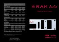
3<br />
4<br />
5<br />
Dual Channel<br />
Parallel Inputs<br />
Single Channel<br />
8
Installation and<br />
Operation<br />
3.2 Troubleshooting<br />
In the event of incorrect connection or<br />
misfunctioning, the amp will activate<br />
one or more of its LED to warn about<br />
the problem.<br />
Correct function: OK/PROT Lights<br />
Green.<br />
ICL: The Intelligent Clip Limiter is operating<br />
(see page 10).<br />
No Signal: (OK/PROT Lights Green)<br />
No Input Signal is reaching the amp.<br />
Overheating: The amplifier has reached<br />
the maximum operational temperature.<br />
Most common cause is: the normal<br />
air flow is blocked, accumulated<br />
dirt, dust or object leaning against the<br />
grill. Check and clean periodically.<br />
Protections: OK/PROT Lights Red.<br />
Several causes can trigger this LED,<br />
most common are:<br />
- Short-circuit in the speakers’ line or in<br />
the speakers themselves.<br />
- Low Impedance: check speakers’ connections<br />
or possible speaker disfunction.<br />
- DC in the output: the protections are<br />
activated to avoid damage to the speakers,<br />
the unit must be sent in for<br />
repair to a qualified technician.<br />
- Delayed Start: As you switch on the<br />
amp the output to the speakers is disconnected.<br />
After a few seconds the<br />
amp will connect the speakers and<br />
proceed with normal functioning.<br />
Anschluss und<br />
Inbetriebnahme<br />
3.2 Problemlösung<br />
Sollte sich irgendeine Fehlfunktion ergeben,<br />
wird diese durch die LED-Anzeigen<br />
auf der Frontplatte gezeigt. Es gibt folgende<br />
Möglichkeiten:<br />
Korrektes Verhalten: OK/PROT<br />
Leuchtet Grün auf<br />
ICL: .Betrieb des ICL (siehe Seite 10)<br />
Kein Signal: (OK/PROT Leuchtet Grün<br />
auf) kein Eingangssignal anwesend.<br />
Überhitzung: Dies kann wegen der<br />
Verschmutzung der Luftein- oder<br />
Austritte geschehen. Es ist angebracht<br />
diese von Zeit zu Zeit zu säubern.<br />
Schutzschaltungen: OK/PROT<br />
Leuchtet Rot auf. Der Eingriff der<br />
Schutzschaltungen kann sich durch folgende<br />
Gründe auslösen:<br />
- Kurzschluss: die Anschlusskabel oder<br />
ggf. die Lautsprecher auf<br />
Kurzschlüsse prüfen.<br />
- Unangebrachte Impedanz: Die<br />
Impedanz der Ausgänge ist zu niedrig.<br />
Instalation auf Fehlanschlüsse testen<br />
oder ggf. Lautsprecher auf Fehler prüfen.<br />
- Gleichstrom: Die Schutzschaltung<br />
greift ein, um die Zerstörung der<br />
Lautsprecher zu vermeiden. Die<br />
Endstufe muss von einem qualifiziertem<br />
Techniker überprüft werden.<br />
- Soft Start: Während des<br />
Inbetriebnahme der Endstufe werden<br />
die Lautsprecher zeitlich ausgeschaltet,<br />
um einen möglichen Schaden zu<br />
vermeiden. Nach einigen Sekunden<br />
schaltet die Endstufe die Lautsprecher<br />
automatisch ein.<br />
9<br />
Installation et<br />
mise en service<br />
3.2 Dysfonctionnements éventuels<br />
En cas d’utilisation incorrecte ou de<br />
dysfonctionnement, une ou plusieurs<br />
LED seront allumées pour indiquer la<br />
nature du problème.<br />
Fonctionnement correct: OK/PROT<br />
Diode Verte allumée<br />
ICL: .Fonctianement du Limiteur<br />
Intelligent d'écretage (voir page 10)<br />
Aucun Signal n’arrive à l’Ampli.<br />
(OK/PROT Diode Verte allumée)<br />
Surchauffe: l’amplificateur a atteint sa<br />
plus haute température interne admissible.<br />
Le plus souvent ceci est dû à un<br />
blocage ou à l’obturation des voies de<br />
ventilation.<br />
Protections: OK/PROT Diode Rouge<br />
allumée. Plusieurs anomalies peuvent<br />
déclencher cet affichage. Les plus courantes<br />
sont:<br />
- Court-circuit sur ligne HP.<br />
- Impédance trop basse pour un fonctionnement<br />
à pleine puissance.<br />
- Courant continu en sortie. Cette protection<br />
est activée pour ne pas<br />
endommager les HP. Confier l’appareil<br />
en SAV à un technicien agréé.<br />
- Temporisation à la mise sous tension.<br />
Les signaux de sortie sont atténués<br />
pendant quelques secondes.
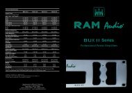
Protection Systems<br />
ICL - Intelligent Clip Limiter<br />
(See Fig 6 )<br />
The <strong>RAM</strong> <strong>Audio</strong> ICL is an anticlip system<br />
that differentiates from conventional clip<br />
reduction systems in its dynamic tracking<br />
of the power supply rail values, to provide<br />
instant current/voltage demand and thereby<br />
eliminating any limiting of the signal<br />
dynamics. More like a valve amplifier,<br />
<strong>RAM</strong> <strong>Audio</strong>'s ICL system maintains sonic<br />
quality even when the amplifiers have<br />
exceeded the threshold of clipping, providing<br />
very high dynamics at negligible distortion<br />
levels.<br />
Commonly the anticlip systems limit the<br />
input signal matching it with to a fixed reference.<br />
The ICL system varies its threshold<br />
reference depending on the status of the<br />
output signal and the power supply rails.<br />
When the system detects the clipping status,<br />
it compares the above mentioned<br />
parameters, then changes the input signal<br />
amplitude to fit the signal between the<br />
supply levels, thus avoiding clipping. This<br />
change is made on the basis of two time<br />
constants, attack and release, this permits<br />
no dynamics loss in the first cycles and<br />
avoids the "pumping" effect.<br />
This system avoids effectively continuous<br />
clipping situations, even when an excessive<br />
signal is applied to the amplifier and<br />
protects the speakers against the high frequency<br />
harmonics produced.<br />
CSP -Continuos Shortcircuit Protection<br />
(See Fig 7 )<br />
The CSP is not a conventional short-circuit<br />
protection at the amplifier's output.<br />
Conventional short-circuit protection systems<br />
rely on simple output current limitation<br />
where excessive current through the<br />
output terminals, continues to be conducted<br />
through the output devices, causing<br />
excessive stress. This may still lead to failure<br />
of the output transistors and associated<br />
circuitry, depending on the nature and<br />
duration of the short circuit.<br />
Also, conventional current limiting systems<br />
find it hard to differentiate between a direct<br />
short circuit across the speaker terminals<br />
and high current transients found in normal<br />
music operation. The SCP is a sophisticated<br />
protection system where the output<br />
current is continually monitored and set<br />
according to the load impedance, relative<br />
to zero ohms impedance.<br />
This allows dynamic performance at relatively<br />
higher current ratings in the case of<br />
music, but much lower current values in<br />
the case of a direct short circuit or excessively<br />
low load impedance.<br />
Schutzschaltungen<br />
System<br />
ICL - Intelligenter Clip-Limiter<br />
(Siehe Fig 6 )<br />
Der <strong>RAM</strong> <strong>Audio</strong> ICL ist ein Anticlipsystem,<br />
welches sich von Anderen darin unterscheidet,<br />
indem es dynamisch die<br />
Gleitwerte der Stromversorgung überprüft,<br />
um so den sofortigen Bedarf an<br />
Strom/Spannung zu verschaffen. Damit<br />
wird jede mögliche Begrenzung der<br />
Signaldynamik beseitigt. Ähnlich einem<br />
Röhrenverstärkers, hält das ICL System<br />
von Ram <strong>Audio</strong> die <strong>Audio</strong>qualität selbst<br />
dann ein, wenn der Verstärker die<br />
Clipschwelle überschritten hat, und bietet<br />
so eine sehr hohe dynamik mit geringfügigen<br />
Verzerrungswerten.<br />
Normalerweise vergleichen anti-clip systeme<br />
den Eingangspegel mit einem festgelegten<br />
Kennwert. Das ICL verändert den<br />
Schwellenwert, abhängig von dem Status<br />
des Ausgangssignals und der Gleitwerte<br />
der Spannungsversorgung. Wenn das<br />
System einen Clip-Zustand ermittelt, vergleicht<br />
es die beiden o.a. Kenngrössen<br />
und passt dann die Amplitude des<br />
Eingangsignals an die Werte der<br />
Stromversorgungswerte an und vermeidet<br />
somit das Clippig. Diese Änderung basiert<br />
auf zwei Zeitkonstanten, die Anfall- und<br />
Abfallzeit und lässt keinen Dynamikverlust<br />
während der ersten Zyklen zu, und vermeided<br />
den "Pumpeffekt".<br />
Dieses System vermeidet wirkungsvoll stetige<br />
Clipzustände, selbst wenn der<br />
Verstärker ein übermässiges Signal erhält<br />
und schützt so die Lautsprecher gegenüber<br />
harmonischer Hochfrequenzen.<br />
CSP- fortdauernden Kurzschlüssen Schutzschaltungen<br />
(Siehe Fig 7 )<br />
Es handelt sich bei dem CSP nicht um<br />
eine übliche Kurzschluss-Schutzschaltung<br />
am Verstärkerausgang.<br />
Handelsübliche Kurzschluss-<br />
Schutzeinrichtungen basieren nur auf<br />
einer einfachen Stromlimitierung wobei der<br />
Stromüberschuss trotzdem weiter durch<br />
die Ausgansschaltung geführt wird und<br />
somit eine Überbelastung erzeugt. Dies<br />
kann immer noch, abhängig von der Natur<br />
und Zeitspanne des Kurzschlusses, zur<br />
Zerstörung der Ausgangstransistoren und<br />
deren verbundenen Schaltkreisen führen.<br />
Konventionelle Stromlimitiervorrichtungen<br />
haben es schwierig einen direkten<br />
Kurzschluss von flüchtigen Hochströmen,<br />
wie sie bei Musikabläufen üblich sind, zu<br />
unterscheiden. Das SCP ist eine fortgeschrittene<br />
Schutzvorrichtung bei welcher<br />
der Ausgangsstrom fortlaufend überwacht<br />
wird und dementsprechend, mit<br />
einem Null-Ohm Stellenwert, and die<br />
Lastimpedanz angepasst wird. Dies ermöglicht<br />
eine dynamische Leistung und vergleichbar<br />
höhere Stromwerte bei<br />
Musikwiedergabe, wobei es gleichzeitig<br />
viel niedrigere Stromwerte im Fall eines<br />
Kurzschlusses oder einer zu niedrigen<br />
impedanz erlaubt.<br />
10<br />
Systèmes de<br />
Protection<br />
ICL - Limiteur Intelligent d'écrêtage<br />
(Voir Fig 6 )<br />
Le système ICL de <strong>RAM</strong> <strong>Audio</strong> est un<br />
système anti-écrêtage très différent des<br />
systèmes conventionnels parce qu'il<br />
mesure les valeurs des rails d'alimentation<br />
en temps reel, pour eviter que le signal en<br />
sortie n'ateigne jamais le point d'ecretage,<br />
en jouant sur le gain instantané du signal,<br />
sans avoir a limiter la dynamique du signal.<br />
Ressemblant dans sa tenue a un<br />
ampli a lampes, le système ICL maintien<br />
la qualité sonique même quand l'amplificateur<br />
a excédé le seuil de l'écrêtage et offre<br />
ainsi un niveau très haut de dynamique a<br />
des niveaux de distorsion négligeables.<br />
Normalement les systèmes anti-écrêtage<br />
limitent le signal d'entrée en le comparant<br />
a une référence fixe. Le ICL par contre,<br />
varie le seuil de référence en relation avec<br />
les statut des signaux d'entrée et des rails<br />
d'alimentation. Quand le système détecte<br />
une situation d'écrêtage, il fait la comparaison<br />
avec les paramètres établis pour<br />
changer l'amplitude du signal d'entrée de<br />
façon a ce qu'il ne dépasse pas les niveaux<br />
des rails d'alimentation et évite ainsi<br />
l'écrêtage. Le changement d'amplitude est<br />
fait sur la base de deux constantes de<br />
temps, l'attaque et la detente, en évitant<br />
des pertes de dynamique dans les premiers<br />
cycles on évite l'effet de "pompage".<br />
Le système ICL évite effectivement les<br />
situations d'écrêtage continu, même<br />
quand un signal excessif est fourni a l'ampli<br />
et surtout protége les systèmes acoustiques<br />
contre les harmoniques de haute et<br />
basse fréquence résultant des écrêtages<br />
non contrôlés.<br />
CSP -Protection Contre les Court-circuits Permanent<br />
(Voir Fig 7 )<br />
Le CSP n'est pas une protection conventionnelle<br />
a la sortie de l'amplificateur.<br />
Les protections conventionnelles se<br />
basent sur la limitation du courant de sortie,<br />
mais n'empêchent pas qu'un courant<br />
excessif continue a passer sur les transistors<br />
et les bornes de sortie, créant un<br />
stress innecessaire a l'appareil. Cette<br />
situation peut mener a une panne des<br />
transistors et ses circuits associes, dépendant<br />
de la nature et portée du court-circuit.<br />
Aussi, les systemes conventionnels de<br />
limitation de courant ont des difficultés a<br />
reconnaître un court-circuit aux bornes,<br />
des transitoires de haut courant qui se<br />
generent dans la reproduction musicale.<br />
Le SCP est un systeme de protection sophistiqué<br />
dans lequel le courant de sortie<br />
est continuellement mesuré et pour deduire<br />
l' impedance de la charge. Ceci permet<br />
une performance dynamique a des valeurs<br />
de courant relativement hautes dans le<br />
cas de la reproduction de musique, mais
Protection Systems<br />
At the onset of current limiting, the SCP<br />
circuit activates, opening the output relay<br />
which disconnects the excessive load.<br />
Every few seconds, the SCP closes the<br />
relay momentarily, to monitor the short circuit,re-opening<br />
instantly if the condition<br />
persists. This cycle repeats until the load<br />
returns to the correct value. The SCP system<br />
saves the output transistors from the<br />
high current stress of short circuits,and in<br />
conjunction with the CRO system, protects<br />
the output relays and all the associated<br />
circuitry.<br />
This highly sophisticated current limiting<br />
system allows improved dynamic sonic<br />
performance at higher power levels, and at<br />
the same time, provides the amplifiers with<br />
a high degree of immunity against continuous<br />
short circuits and mismatched<br />
loads.<br />
CRO - Currentless Relay Operation<br />
(See Fig 8 )<br />
The CRO is a system that protects the<br />
amplifier components and avoids transient<br />
situations at the speaker outputs when the<br />
output relay opens due to an abnormal<br />
event (high temperature, short-circuit, etc).<br />
In a conventional amplifier the relay operates<br />
with all the signal voltage between its<br />
contacts and has to interrupt all the<br />
current this voltage produces through the<br />
load. This type of operation reduces considerably<br />
the relay's life because of the electric<br />
arc generated between the contacts.<br />
This arc may damage the contacts permanently<br />
or at the least, increase the contact<br />
resistance, decreasing the damping factor<br />
dramatically.<br />
On the other hand, the speakers must be<br />
isolated from all the unpredictable situations<br />
taking place between the open and<br />
closed status of the relay contacts,- which<br />
may include the electric arc generation-, to<br />
protect them from spurious high frequency<br />
signals that may damage them.<br />
<strong>RAM</strong> <strong>Audio</strong> has developed the CRO protection<br />
system to avoid those dangerous<br />
situations. Basically, the CRO anticipates<br />
to the opening or closing of the output<br />
relay acting on the input signal, muting it,<br />
to permit the relay contacts to work always<br />
with zero current. If the relay operates, the<br />
contacts close first and then the signal is<br />
let through. If the relay is going to open,<br />
the signal is muted first and then the contacts<br />
open. The delay between the signal<br />
muting and the contacts opening or closing<br />
is negligible and the listener will not<br />
notice any evidence of the CRO system<br />
working. Additionally The CRO system<br />
applies the signal with a ramp envelope to<br />
avoid the instantaneous volume increase<br />
when the signal is applied to the amplifier<br />
as the relay closes.<br />
Schutzschaltungen<br />
System<br />
Wenn der Stromlimitierer eingreift, wird die<br />
SCP-Schaltung aktiv und öffnet ein<br />
Ausgangsrelais, welches die Überlast<br />
ausschaltet. Alle wenige Sekunden schliesst<br />
das SCP das Relais momentan wieder,<br />
überwacht den Kurzschluss und öffnet<br />
sich sofort wieder, wenn dieser Zustand<br />
weiter besteht. Dieser Zyklus wird wiederholt<br />
bis die Last zu einem angemessenem<br />
Wert wiederhergestellt wird. Zusammen<br />
mit dem CRO system werden die<br />
Ausgangsrelais und die damit verbundenen<br />
Schaltungen geschützt.<br />
Dieses hochentwickelte System ermöglicht<br />
es, eine verbesserte und dynamische<br />
Durchführung, selbst bei starken<br />
Leistungswerten, zu erreichen und schützt<br />
gleichzeitig den Verstärker vor fortdauernden<br />
Kurzschlüssen und falsch angepassten<br />
Lasten.<br />
CRO - ohne Strom Relais Arbeit<br />
(Siehe Fig 8 )<br />
Das CRO-System schützt die<br />
Verstärkerbauteile und vermeidet vorrübergehende<br />
Situationen an den<br />
Lautsprecherausgängen, wenn das<br />
Ausgangsrelais wegen einer unregelmässigen<br />
Situation (wie z.B. Überhitzung oder<br />
Kurzschlüsse) sich öffnet.<br />
In üblichen Verstärkern arbeitet das Relais<br />
während sich die volle Signalspannung<br />
zwischen den Kontakten befindet und<br />
muss den ganzen Strom, den diese<br />
Spannung erzeugt, unterbrechen. Dieser<br />
Vorgang verrringert, durch den erzeugten<br />
Lichtbogen, die Lebensdauer des Relais<br />
drastisch. Dieser Lichtbogen kann die<br />
Relaiskontakte endgültig zerstören oder<br />
mindestens den Kontaktwiderstand so weit<br />
erhöhen dass der Dämpfungsfaktor erheblich<br />
steigt.<br />
Ausserdem müssen die Lautsprecher von<br />
allen möglichen unvorsehbaren<br />
Situationen zwischen dem offenen und<br />
geschlossene Zustand des Relais isoliert<br />
werden, wie z. B. der schon erwähnte<br />
Lichtbogen, um ihn damit vor störenden<br />
und zerstörenden Hochfrequenzsignalen<br />
zu schützen.<br />
Das CRO-Schutz ist von <strong>RAM</strong> <strong>Audio</strong> entwickelt<br />
woden, um diese gefährlichen<br />
Zustände zu vermeiden. Im Prinzip arbeitet<br />
der CRO folgend: Das CRO sieht das<br />
Öffnen und Schliessen des Relais voraus<br />
und wirkt auf das Eingangssignal ein,<br />
indem es es dämpft. Damit arbeitet das<br />
Relais immer ohne Strom zwischen den<br />
Kontakten. Wenn das Relais öffnet, wird<br />
erst das Signal gedämpft; danach erst<br />
schaltet das Relais. Die Verzögerungszeit<br />
zwischen der Signaldämpfung und der<br />
Kontaktöffnung oder -Schliessung ist<br />
unbedeutend, so dass der Hörer das<br />
CRO-System nicht bemerken wird.<br />
Ausserdem wird das CRO eine<br />
Anstiegsrampe anwenden. Damit wird ein<br />
heftiger Lautstärkeanstieg vermieden,<br />
wenn das Relais schliesst und das Signal<br />
angelegt wird.<br />
11<br />
Systèmes de<br />
Protection<br />
tres faibles dans le cas d'un court-circuit<br />
ou une trop basse impedance.<br />
Au moment de la limitation du courant, le<br />
circuit du SCP s'active en ouvrant le relais<br />
de sortie qui coupe le courant. Toutes les<br />
quelques secondes, le CSP teste le status<br />
et detecte si la situation persiste. Ce cycle<br />
se repete jusqu'à ce que la situation<br />
devienne normale. Le SCP protege les<br />
transistors de sortie des stress provoqués<br />
par les court-circuits et avec le systeme<br />
CRO assure la longeveite des relais de<br />
sortie et leur circuits associés.<br />
Ce systeme de limitation de courant permet<br />
des performances ameliorées et des<br />
niveaux de puissance tres elevés tout en<br />
offrant une assurance contre les court-circuits<br />
permanents et les charges inadequates.<br />
CRO -Fonctionnement des Relais Sans Courant<br />
(Voir Fig 8 )<br />
Le CRO est un système qui protége les<br />
composants électroniques et évite les<br />
transitoires a la sortie des haut-parleurs,<br />
quand les relais s'ouvrent pour mettre<br />
l'ampli en attente : (température excessive,<br />
court-circuit, mise en route, etc.)<br />
Dans un ampli conventionnel les relais<br />
fonctionnent avec toute la tension du signal<br />
entre ses contacts et doit interrompre<br />
tout le courant que ce voltage produit sur<br />
la charge. Ce genre d'opération réduit<br />
considérablement la vie utile des relais a<br />
cause des arcs électriques générés entre<br />
les contacts. Ces arcs peuvent endommager<br />
les contacts de façon permanente ou<br />
dans le meilleur des cas, augmenter la<br />
résistance des contacts, et réduire fortement<br />
le facteur d'amortissement.<br />
Par ailleurs, les haut parleurs devraient s'isoler<br />
des situations imprévisibles qui peuvent<br />
avoir lieu entre l'ouverture et la fermeture<br />
des contacts, inclus la génération<br />
des arcs électriques, pour les protéger des<br />
signaux excessifs qui pourraient les<br />
endommager.<br />
<strong>RAM</strong> <strong>Audio</strong> a développe le système de<br />
protection CRO pour éviter ces situations<br />
dangereuses. Dans la pratique le CRO<br />
s'anticipe a l'ouverture et la fermeture des<br />
contacts en " mutant " le signal de sortie.<br />
Ceci leur permet de travailler avec un courant<br />
nul et le signal ne circule qu'une fois<br />
les contacts fermés. Le délai temporel<br />
entre le silencement du signal et l'ouverture<br />
ou la fermeture des contacts est négligeable<br />
et l'auditeur ne décèlera jamais le<br />
CRO au travail. De plus Le système CRO<br />
réactive le signal en rampe pour éviter le<br />
gain de volume instantané que l'amplificateur<br />
aurait a supporter.
6 7<br />
8<br />
12
Technical<br />
Tecnische<br />
Specifications Spezifikationen<br />
Spécifications<br />
4.2 Data 4.2 Technische Daten<br />
4.2 Données techniques<br />
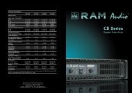
Technical Specifications<br />
<strong>DQX</strong>-<strong>2.4</strong> <strong>DQX</strong>-<strong>4.0</strong> <strong>DQX</strong>-<strong>5.5</strong> <strong>DQX</strong>-<strong>7.0</strong><br />
Output Power<br />
Continuous Average Power<br />
RMS, 1kHz, 1.0% THD+N<br />
@ 2Ω 2x 1200 W 2x 1950 W 2x 2700 W 2x 3450 W<br />
@ 4Ω 2x 800 W 2x 1300 W 2x 1800 W 2x 2300 W<br />
@ 8Ω 2x 450 W 2x750 W 2x1000 W 2x 1300 W<br />
Bridge @ 4Ω 2400 W 3900 W 5400 W 6900 W<br />
Bridge @ 8Ω<br />
Pink Noise 12dB Crest Factor<br />
1600 W 2600 W 3600 W 4600 W<br />
@ 2Ω 2x 1600 W 2x 2600 W 2x 3600 W 2x 4600 W<br />
@ 4Ω<br />
Frequency Response<br />
2x 950 W 2x 1580 W 2x 2100 W 2x 2700 W<br />
Power Bandwidth ±0.25dB<br />
Phase Response<br />
20Hz-20kHz 20Hz-20kHz 20Hz-20kHz 20Hz-20kHz<br />
@ 1 watt 20Hz-20kHz<br />
Total Harmonic Distortion<br />
±15 deg ±15 deg ±15 deg ±15 deg<br />
20Hz-20kHz<br />
Intermodulation Distortion<br />
65 V/µs<br />
20Hz-1kHz >800 >800 >800 >800<br />
Voltage Gain<br />
Sensitivity<br />
26/32/38 dB 26/32/38 dB 26/32/38 dB 26/32/38 dB<br />
Rated Power @ 8Ω<br />
Signal-to-Noise Ratio<br />
3/1.5/0.8 V 3.9/1.9/1 V 4.5/2.2/1.1 V 5.1/2.6/1.3 V<br />
A weighted<br />
Required AC Mains<br />
104 dB 105 dB 106 dB 107 dB<br />
230 V - 50 Hz (idle) 0.5A 0.5A 0.5A 0.5A<br />
@ 4Ω (1/8 rated power)<br />
Dimensions<br />
4 A 7 A 10 A 13 A<br />
W x H x D (mm) 483x89x460 483x89x460 483x89x460 483x89x460<br />
W x H x D (inches)<br />
Weight<br />
19x3.5x18.1 19x3.5x18.1 19x3.5x18.1 19x3.5x18.1<br />
Shipping 14Kg-30.4Lbs 14Kg-30.4Lbs 15Kg-32.6Lbs 15Kg-32.6Lbs<br />
Net 13Kg-28.3Lbs 13Kg-28.3Lbs 14Kg-30.4Lbs 14Kg-30.4Lbs<br />
13
Manufactured in the EEC by C.E. Studio-2 s.l.<br />
Pol. Ind. La Lloma - C/Sierra Perenxisa nº28<br />
46960 Aldaya - Valencia - SPAIN<br />
Phone: +34 96 127 30 54 Fax: +34 96 127 30 56<br />
http://www.ramaudio.com e-mail: support@ramaudio.com