
Create successful ePaper yourself
Turn your PDF publications into a flip-book with our unique Google optimized e-Paper software.
2<br />
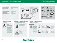
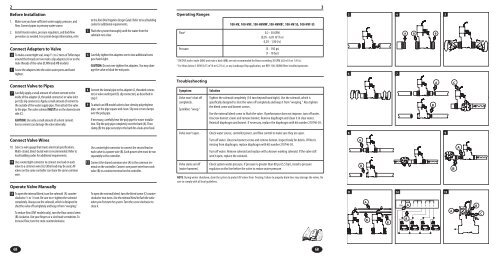
Before Installation<br />
1. Make sure you have sufficient water supply, pressure, and<br />
flow. Connect pipes to primary water source.<br />
2. Install master valves, pressure regulators, and backflow<br />
preventers as needed. For system design information, refer<br />
Connect Adapters to Valve<br />
4. To make a watertight seal, wrap 1 4<br />
⁄2 to 2 turns of Teflon tape<br />
around the threads on two male x slip adapters (A) or on the<br />
male threads of the valve (B; MM and MB models)<br />
5. 5 Screw the adapters into the valve water ports and hand<br />
tighten.<br />
Connect Valve to Pipes<br />
7. 7 Carefully apply a small amount of solvent cement to the<br />
inside of the adapter (A, threaded connector) or valve inlet<br />
port (B, slip connector). Apply a small amount of cement to<br />
the outside of the water supply pipe. Then attach the valve<br />
to the pipe. The valve solenoid MUST be on the downstream<br />
side (C).<br />
CAUTION: Use only a small amount of solvent cement.<br />
Excess cement can damage the valve internally.<br />
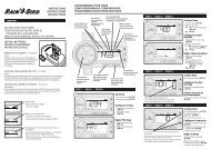
Connect Valve Wires<br />
10. Select a wire gauge that meets electrical specifications.<br />
Multi-strand, direct-burial wire is recommended. Refer to<br />
local building codes for additional requirements.<br />
11. 11 Use a watertight connector to connect one lead on each<br />
valve to a common wire (A). Either lead may be used. All<br />
valves on the same controller can share the same common<br />
wire.<br />
Operate Valve Manually<br />
13 To open the internal bleed, turn the solenoid (A) counterclockwise<br />
1 ⁄4 to 1 13<br />
⁄2 turn. Be sure to re-tighten the solenoid<br />
completely. Always use the solenoid, which is designed to<br />
shut the valve off completely and keep it from “weeping.”<br />
To reduce flow (DVF models only), turn the flow control stem<br />
(B) clockwise. Use your fingers or a slot-head screwdriver. To<br />
increase flow, turn the stem counterclockwise.<br />
GB<br />
to the <strong>Rain</strong> <strong>Bird</strong> lrrigation Design Guide. Refer to local building<br />
codes for additional requirements.<br />
3. 3 Flush the system thoroughly until the water from the<br />
submain runs clear.<br />
6<br />
Carefully tighten the adapters one to two additional turns<br />
past hand-tight.<br />
CAUTION: Do not over-tighten the adapters. You may damage<br />
the valve or block the exit ports.<br />
8. 8 Cement the lateral pipe to the adapter (A, threaded connector)<br />
or valve outlet port (B, slip connector), as described in<br />
step 7.<br />
9. 9 To attach an MB model valve to low-density polyethylene<br />
pipe, cut the pipe square and clean. Slip one or two clamps<br />
over the poly pipe.<br />
If necessary, carefully heat the poly pipe for easier installation.<br />
Slip the poly pipe completely over the barb (A). Then<br />
clamp (B) the pipe securely to the barb for a leak-proof seal.<br />
Use a watertight connector to connect the second lead on<br />
each valve to a power wire (B). Each power wire must be run<br />
separately to the controller.<br />
12. 12 Connect the shared common wire (A) to the common terminal<br />
on the controller. Connect one power wire from each<br />
valve (B) to a station terminal on the controller.<br />
To open the external bleed, turn the bleed screw (C) counterclockwise<br />
two turns. Use the external bleed to flush the valve<br />
when you first start the system. Turn the screw clockwise to<br />
close it.<br />
Operating Ranges<br />
Troubleshooting<br />
Symptom Solution<br />
Valve won’t shut off<br />
completely.<br />
Sprinklers “weep.”<br />
Tighten the solenoid completely (1⁄4 turn beyond hand tight). Use the solenoid, which is<br />
specifically designed to shut the valve off completely and keep it from “weeping.” Also tighten<br />
the bleed screw and bonnet screws.<br />
Use the external bleed screw to flush the valve. If performance does not improve, turn off water.<br />
Unscrew bonnet screws and remove bonnet. Remove diaphragm and clean it in clear water.<br />
Reinstall diaphragm and bonnet. If necessary, replace the diaphragm with kit number 210746-03.<br />
Valve won’t open. Check water source, controller power, and flow control to make sure they are open.<br />
Valve slams on/off<br />
(water hammer).<br />
100-<strong>HV</strong>, 100-<strong>HV</strong>F, 100-<strong>HV</strong>MM 1 ,100-<strong>HV</strong>MB 1 , 100-<strong>HV</strong>-SS, 100-<strong>HV</strong>F-SS<br />
Flow 2 0.2 - 30 GPM<br />
(0,05 - 6,81 m 3 /h or<br />
0,O1 - 1,90 I/s)<br />
Pressure 15 - 15O psi<br />
(1 - 10 bar)<br />
1 DV/DVF male x male (MM) and male x barb (MB) are not recommended for flows exceeding 30 GPM (6,8 m 3 /h or 1,9 I/s).<br />
2 For flows below 3 GPM (0,75 m 3 /h or 0,21 I/s), or any Landscape Drip application, use RBY-100-200MX filter installed upstream.<br />
Turn off water. Unscrew bonnet screws and remove bonnet. Inspect body for debris. If filter is<br />
missing from diaphragm, replace diaphragm with kit number 210746-03.<br />
Turn off water. Remove solenoid and replace with a known working solenoid. If the valve still<br />
won’t open, replace the solenoid.<br />
Check system water pressure. If pressure is greater than 80 psi (5,5 bar), install a pressure<br />
regulator on the line before the valve to reduce water pressure.<br />
NOTE: During winter shutdown, drain the system to protect DV valves from freezing. Failure to properly drain lines may damage the valves. Be<br />
sure to comply with all local guidelines.<br />
GB<br />
3<br />
3<br />
6 7<br />
8<br />
11<br />
A<br />
B<br />
A<br />
B<br />
B<br />
4 5<br />
A<br />
B B<br />
12 13<br />
COM A 1 2 3 4 5 6<br />
B<br />
B<br />
A C<br />
9<br />
A<br />
B<br />
A<br />
B<br />
C