
You also want an ePaper? Increase the reach of your titles
YUMPU automatically turns print PDFs into web optimized ePapers that Google loves.
Introduction<br />
The Vetus exhaust system <strong>com</strong>ponents are especially suitable<br />
for use in water-injected exhaust systems.<br />
The maximum continuous operating temperature of the plastic<br />
<strong>com</strong>ponents of the exhaust systems is 70 degrees C (158<br />
degrees F).<br />
The <strong>MGP</strong> waterlocks are available with the following intake<br />
connections: 45° upward angle (standard), 30° upward angle<br />
(on request), 15° upward angle (on request), and horizontal (on<br />
request).<br />
• Fit a temperature alarm to warn of excessively hot<br />
exhaust system temperature<br />
• If the quantity of injected coolant water is reduced to<br />
in order to lower back-pressure in the exhaust system,<br />
check that there is still sufficient water injected when<br />
the engine is ticking-over. This will prevent excess temperatures<br />
in the exhaust system<br />
• Excess temperature can also be the consequence of<br />
insufficient mixing of coolant water with the exhaust<br />
gasses<br />
In general, good mixing is obtained by a virtually vertically<br />
installed exhaust injection bend<br />
Poor mixing can also occur with an engine on tick-over;<br />
especially when the coolant water injection bend is<br />
installed virtually horizontally<br />
If necessary, take action. For example; by fitting a water<br />
vortex or a water splitter in the exhaust pipe, to improve<br />
the mixing of coolant water with the exhaust gasses<br />
With water-injected exhaust systems, fit a hose of suitable quality.<br />
This hose must be reinforced, resistant to exhaust gasses, high<br />
temperatures (100 degrees C, 212 degrees F) and oil. Easy<br />
flexibility is essential for installation, while the hose must not<br />
collapse when heated.<br />
Vetus exhaust hose fulfils all the above requirements.<br />
4 030421.03<br />
WARNING<br />
If water enters the engine from the waterlock into the<br />
exhaust system (for example: under sail when the ship<br />
rolls or pitches heavily) this will lead to irreparable damage<br />
to the engine.<br />
Too much water in the waterlock can effect engine starting;<br />
drain off this water first. Too much water in the waterlock<br />
can be also caused by repeated starting attempts<br />
while the engine refuses to start.<br />
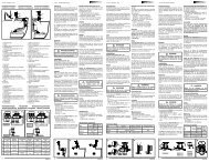
Installation<br />
Installing waterlock <strong>MGP</strong><br />
Instal the waterlock as vertical as possible.<br />
The waterlock ‘IN’-connection must always remain below the<br />
level of the exhaust injection bend! Position the waterlock<br />
‘back-to-front’ alongside the engine when there is insufficient<br />
space behind the engine.<br />
During operation, the waterlock will contain water. Its weight will<br />
thus increase considerably.<br />
Fit the waterlock on a level surface and attach it with M8 bolts<br />
and 3D flat washers.<br />
Installing the transom exhaust connection<br />
Fit the transom exhaust connection at such a position that with<br />
the ship fully laden, the outlet is still at least 5 cm (2”) above<br />
the waterline.<br />
Exhaust pipe<br />
In order to ensure the proper drainage of the coolant water<br />
injected into the exhaust pipe, the pipe must be installed with a<br />
slope downward over its whole length from the water injection<br />
point to the waterlock.<br />
During operation, the exhaust pipe will contain water. This will<br />
increase its weight considerably, so support the exhaust pipe<br />
properly.<br />
The exhaust pipe from waterlock to transom connection must<br />
be installed in such a way that:<br />
- The highest point in the exhaust pipe should not be more<br />
than 150 cm (60”) above the underside of the waterlock.<br />
- The length of the section between the waterlock and the<br />
highest point, should not exceed 300 cm (120”).<br />
Waterlock <strong>MGP</strong>