SC.P30QIS SC.P30QES
SC.P30QIS SC.P30QES
SC.P30QIS SC.P30QES

You also want an ePaper? Increase the reach of your titles
YUMPU automatically turns print PDFs into web optimized ePapers that Google loves.
L8542339<br />
Rev. 11/07/01<br />
24Vac-Vdc+<br />
TX RX<br />
+ -<br />
JP2 Open<br />
SYNC OFF<br />
SYNC<br />
Fig.2<br />
<strong>SC</strong>.<strong>P30QIS</strong><br />
<strong>SC</strong>.<strong>P30QES</strong><br />
+ -<br />
C NO NC<br />
1 2 1 2 3 4 5<br />
TX1 RX1<br />
+ -<br />
24 Vac<br />
JP2 Close<br />
SYNC ON<br />
SYNC<br />
TX1<br />
TX2<br />
JP2 Close<br />
SYNC ON<br />
SYNC<br />
+ - C NO NC<br />
+<br />
24Vac-Vdc<br />
TX2 RX2<br />
+ -<br />
JP2 Close<br />
SYNC ON<br />
SYNC<br />
2 coppie - 2 pairs - 2 fotozellenpaare<br />
2 couples - 2 paejas - 2 par<br />
JP2 Close<br />
SYNC ON<br />
SYNC<br />
+ - C NO NC<br />
RX1<br />
RX2<br />
JP2 Open<br />
SYNC OFF<br />
SYNC<br />
A<br />
Fig.4<br />
LED<br />
COM<br />
3<br />
40-60cm<br />
NO<br />
Fig.5 Fig.6<br />
B<br />
TX1<br />
TX2<br />
NC<br />
TX1 RX1<br />
+ -<br />
24 Vac<br />
4<br />
5<br />
JP2 Close<br />
SYNC ON<br />
SYNC<br />
COM<br />
3<br />
RX3<br />
RX4<br />
Fig.3<br />
JP2 Close<br />
SYNC ON<br />
SYNC<br />
+ - C NO NC<br />
+ -<br />
Fig.1<br />
NO<br />
NC<br />
4<br />
5<br />
JP2 Close<br />
SYNC ON<br />
SYNC<br />
COM<br />
3<br />
TX2 RX2<br />
TX3 RX3<br />
+ -<br />
JP2 Close<br />
SYNC ON<br />
SYNC<br />
TX4 RX4<br />
RX1<br />
RX2<br />
+ -<br />
JP2 Close<br />
SYNC ON<br />
SYNC<br />
Power OFF<br />
JP2 Close<br />
SYNC ON<br />
SYNC<br />
+ - C NO NC<br />
JP2 Close<br />
SYNC ON<br />
SYNC<br />
+ - C NO NC<br />
JP2 Close<br />
SYNC ON<br />
SYNC<br />
+ - C NO NC<br />
NO<br />
NC<br />
2+2 coppie - 2+2 pairs<br />
2+2 fotozellenpaare - 2+2 couples<br />
2+2 paejas - 2+2 par<br />
TX3<br />
TX4<br />
4<br />
5<br />
ITALIANO<br />
FOTODISPOSITIVI DA INCASSO E DA ESTERNO A<br />
LUCE MODULATA CON DUE RELE’<br />
DE<strong>SC</strong>RIZIONE<br />
Fotodispositivo costituito da un ricevitore e da un trasmettitore a luce<br />
infrarossa modulata.<br />
Il corretto allineamento della coppia trasmettitore-ricevitore viene visualizzato<br />
da un led sul ricevitore: è quindi possibile una facile e accurata<br />
installazione.<br />
POSSIBILITA’ DI IMPIEGO<br />
Viene impiegato per la protezione di porte, cancelli e accessi automatizzati<br />
in genere.<br />
INSTALLAZIONE E ALLINEAMENTO<br />
1) Murare o fissare con le apposite quattro viti il contenitore dei dispositivi,<br />
tenendo conto che per una corretta installazione il trasmettitore e il ricevitore<br />
devono essere montati in posizione frontale e allineati sullo stesso<br />
asse (fig. 1).<br />
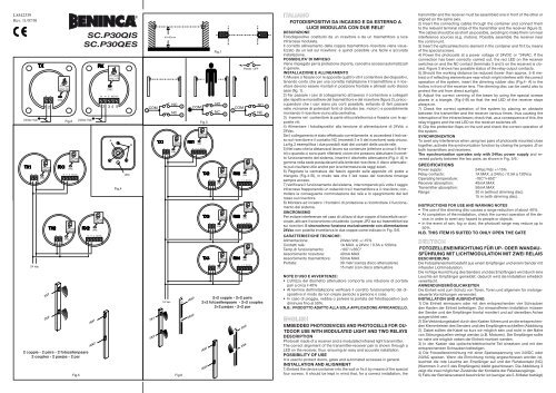
2) Far passare i cavi di collegamento attraverso il contenitore e collegarli<br />
alle rispettive morsettiere del trasmettitore e del ricevitore (figura 2), preoccupandosi<br />
che i cavi siano più corti possibile, evitando di farli passare<br />
nelle vicinanze di potenziali fonti di disturbo (es. motori ) e possibilmente<br />
montando il ricevitore vicino alla centralina.<br />
3) Inserire nel contenitore la parte ottico/elettronica e fissarla con le apposite<br />
viti.<br />
4) Alimentare i fotodispositivi alla tensione di alimentazione di 24Vdc o<br />
24Vac.<br />
Se il collegamento è stato effettuato correttamente si accenderà il led rosso<br />
sul ricevitore e il contatto NC (morsetti 3 e 5 del ricevitore) sarà chiuso.<br />
La fig.3 esemplifica i due possibili stati dei contatti delle uscite relè.<br />
5) Nel caso che la distanza di lavoro sia contenute (inferiore a circa 5-8 metri)<br />
o quando ci sono parti riflettenti vicine che possono disturbare il corretto<br />
funzionamento del sistema, inserire il dischetto attenuatore (Fig.4- A) in<br />
gomma nella sede posta davanti alla lente del ricevitore. Il disco attenuatore<br />
può risultare utile anche per la schermatura da raggi solari.<br />
6) Regolare la centratura del fascio agendo sulle apposite viti poste a<br />
triangolo (Fig.4-B), in modo tale che il led rosso del ricevitore rimanga<br />
sempre acceso.<br />
7) Verificare il funzionamento del sistema, interrompendo più volte il raggio<br />
infrarosso frapponendo un ostacolo tra il trasmettitore e il ricevitore; controllare<br />
la conseguente commutazione dei relè e lo spegnimento del led<br />
rosso sul ricevitore.<br />
8) Montare ad incastro i frontalini di protezione e ricontrollare il funzionamento<br />
del sistema.<br />
SINCRONISMO<br />
Per evitare interferenze nel caso di utilizzo di due coppie di fotocellule ravvicinate,<br />
attivare il sincronismo chiudendo i jumper JP2 sia sui trasmettitori sia<br />
sui ricevitori. Il sincronismo funziona esclusivamente con alimentazione<br />
24Vac con polarità invertita tra le due coppie come indicato in Fig. 5/6.<br />
CARATTERISTICHE TECNICHE:<br />
Alimentazione: 24Vac/Vdc +/-15%<br />
Contatti relè: 1A MAX. a 24Vcc / 0.5A a 120Vca<br />
Temp.di funzionamento: -10C°/+65C°<br />
Assorbimento ricevitore: 40mA MAX<br />
Assorbimento trasmettitore: 50mA MAX<br />
Portata: 30 metri (senza disco attenuatore)<br />
15 metri (con disco attenuatore<br />
NOTE D’USO E AVVERTENZE:<br />
• L’utilizzo del dischetto attenuatore comporta una riduzione di portata<br />
pari a circa il 40%<br />
• Al termine dell’installazione verificare il corretto funzionamento del dispositivo<br />
in modo da non creare pericolo a persone o cose.<br />
• In caso di pioggia, nebbia o polvere la portata del fotodispositivo può<br />
diminuire fino al 50%.<br />
N.B.: PRODOTTO ADATTO ALLA SOLA APPLICAZIONE APRICANCELLO.<br />
ENGLISH<br />
EMBEDDED PHOTODEVICES AND PHOTOCELLS FOR OU-<br />
TDOOR USE WITH MODULATED LIGHT AND TWO RELAYS<br />
DE<strong>SC</strong>RIPTION<br />
Photocell made of a receiver and a modulated infrared light transmitter.<br />
The correct alignment of the transmitter-receiver pair is shown through a<br />
LED on the receiver, thus ensuring an easy and accurate installation.<br />
POSSIBILITY OF USE<br />
It is used to protect doors, gates and automated accesses in general.<br />
INSTALLATION AND ALIGNMENT<br />
1) Embed the device container into the wall or fix it by means of the special<br />
four screws. It should be kept in mind that, for a correct installation, the<br />
transmitter and the receiver must be assembled one in front of the other or<br />
aligned on the same axis.<br />
2) Insert the connecting cables through the container and connect them<br />
to the relevant terminal strips of the transmitter and the receiver (figure 2).<br />
The cables should be as short as possible, avoiding to make them run near<br />
interference sources (e.g. motors). Possibly assemble the receiver near<br />
the control unit.<br />
3) Insert the optical/electronic element in the container and fit it by means<br />
of the special screws.<br />
4) Power the photocells at a power voltage of 24VDC or “24VAC. If the<br />
connection has been correctly carried out, the red LED on the receiver<br />
switches on and the NC contact (terminals 3 and 5 on the receiver) is closed.<br />
Figure 3 shows two possible status of the relay output contacts.<br />
5) Should the working distance be reduced (lower than approx. 5-8 metres)<br />
or if reflecting elements are near which might interfere with the correct<br />
operation of the system, insert the dimming rubber disc (Fig.4- A) in the<br />
hollow in front of the receiver lens. The dimming disc can be useful also to<br />
protect the unit from direct sunlight.<br />
6) Adjust the correct centring of the beam by using the special screws<br />
places in a triangle, (Fig.4-B) so that the red LED of the receiver stays<br />
always on.<br />
7) Check the correct operation of the system by placing an obstacle<br />
between the transmitter and the receiver various times, thus causing the<br />
interruption of the infrared beam; check that, as a consequence of this, the<br />
relay triggers and the red LED on the receiver switches off.<br />
8) Clip the protection flaps on the unit and check the correct operation of<br />
the system.<br />
SYNCHRONIZATION<br />
To avert any interference when using two pairs of photocells mounted close<br />
together, activate the synchronization function by closing the jumpers J2 on<br />
both transmitters and receivers.<br />
The synchronization operates only with 24Vac power supply and reversed<br />
polarity between the two pairs, as shown in Fig. 5/6.<br />
SPECIFICATIONS<br />
Power supply: 24Vac/Vdc +/-15%<br />
Relay contacts: 1A MAX. a 24Vcc / 0.5A a 120Vca<br />
Operating temperature: -10C°/+65C°<br />
Receiver absorption: 40mA MAX<br />
Transmitter absorption: 50mA MAX<br />
Range: 30 m (without dimming disc)<br />
15 m (with dimming disc).<br />
INSTRUCTIONS FOR USE AND WARNING NOTES<br />
• The use of the dimming disc causes a range reduction of about 40%.<br />
• At completion of the installation, check the correct operation of the device,<br />
in order to avert any hazard to people or objects.<br />
• In the event of rain, fog or dust, the photocell range may reduce up to<br />
50%.<br />
N.B. THIS ITEM IS SUITED TO ONLY OPEN THE GATE<br />
DEUT<strong>SC</strong>H<br />
FOTOZELLENEINRICHTUNG FÜR UP- ODER WANDAU-<br />
SFÜHRUNG MIT LICHTMODULATION MIT ZWEI RELAIS<br />
BE<strong>SC</strong>HREIBUNG<br />
Die Fotozelleneinheit besteht aus einem Empfänger und einem Sender mit<br />
infraroter Lichtmodulation.<br />
Die richtige Ausrichtung des Senders und des Empfängers wird durch eine<br />
Leuchte am Empfänger gemeldet: dadurch wird die Installation erheblich<br />
vereinfacht.<br />
ANWENDUNGSMÖGLICHKEITEN<br />
Die Einheit wird zum Schutz von Türen, Toren und allgemein für motorgesteuerte<br />
Vorrichtungen verwendet.<br />
INSTALLATION UND AUSRICHTUNG<br />
1) Die Einheit einmauern oder mit den entsprechenden vier Schrauben<br />
den Kasten der Einheit befestigen. Zur einwandfreien Installation müssen<br />
der Sender und der Empfänger frontal montiert und auf derselben Achse<br />
ausgerichtet sein.<br />
2) Die Verbindungskabel durch den Kasten führen und an die entsprechenden<br />
Klemmleisten des Senders und des Empfängers schließen (Abbildung<br />
2). Dabei sollten die Kabel so kurz wir möglich sein und nicht in der Nähe<br />
von Störungsquellen verlegt werden (z.B. Motoren). Der Empfänger sollte<br />
so nahe wie möglich neben der Einheit montiert werden.<br />
3) In den Kasten das optische/elektronische Teil einsetzen und mit den<br />
entsprechenden Schrauben befestigen.<br />
4) Die Fotozelleneinrichtung mit einer Speisespannung von 24VDC oder<br />
24VAC speisen. Wenn die Einrichtung richtig angeschlossen worden ist,<br />
leuchtet die rote Leuchte am Empfänger auf und der Ruhekontakt (NC)<br />
(Klemmen 3 und 5 des Empfängers) bleibt geschlossen. Die Abbildung 3<br />
zeigt die zwei möglichen Zustände der Kontakte der Relaisausgänge.<br />
5) Falls der Betriebszustand beschränkt ist (weniger als 5-8 Meter beträgt)
oder wenn sich in der Nähe rückstrahlende Teile befinden, die den einwandfreien<br />
Betrieb des Systems beeinträchtigen könnten, eine Dämpfungsscheibe<br />
aus Gummi (Abb .4- A) in den Sitz vor der Linse des Empfängers<br />
einsetzen. Die Dämpfungsscheibe kann auch als Abschirmung vor Sonnenstrahlen<br />
nützlich sein.<br />
6) Den Lichtstrahl durch die entsprechenden im Dreieck angebrachten<br />
Schrauben einstellen (Abb.4- B), so dass die rote Leuchte des Empfängers<br />
ständig eingeschaltet bleibt.<br />
7) Den Betrieb des Systems kontrollieren und dazu mehrmals den Lichtstrahl<br />
mit einem Hindernis zwischen Sender und Empfänger unterbrechen;<br />
kontrollieren, ob dabei das Relais umschaltet und die rote Leuchte<br />
am Empfänger ausschaltet.<br />
8) Die Frontplatten einrasten und den Betrieb des Systems nochmals<br />
kontrollieren.<br />
SYNCHRONISMUS<br />
Falls zwei nahliegende Fotozellenpaare verwendet werden, den Synchronismus<br />
aktivieren, um Störungen zu vermeiden. Dazu die Jumpers JP2 an den<br />
Sendegeräten und an den Empfängern schließen.<br />
Der Synchronismus funktioniert ausschließlich mit einem Netzgerät<br />
24Vac mit umgetauschten Polenpaaren, wie in Abb. 5/6 gezeigt.<br />
TECHNI<strong>SC</strong>HE EIGEN<strong>SC</strong>HAFTEN:<br />
Speisung: 24Vac/Vdc +/-15%<br />
Relaiskontakte: 1A MAX. a 24Vcc / 0.5A a 120Vca<br />
Betriebstemperatur: -10C°/+65C°<br />
Stromaufnahme Empfänger: 40mA MAX<br />
Stromaufnahme Sender: 50mA MAX<br />
Tragweite: 30 m ( ohne Dämpfungsscheibe )<br />
15 Meter (mit Dämpfungsscheibe)<br />
GEBRAUCHSANWEISUNGEN UND HINWEISE<br />
• Wenn die Dämpfungsscheibe verwendet wird, verringert sich die Tragweite<br />
um ca. 40%.<br />
• Nachdem die Installation beendet worden ist, kontrollieren ob die Vorrichtung<br />
richtig funktioniert und keine Gefahr für Menschen oder Gegenstände<br />
darstellen kann.<br />
• Bei Regen, Nebel oder Staub, kann die Tragweite der Fotozellen bis zu<br />
50% verringert werden.<br />
N.B. DAS PRODUKT EIGNET SICH NUR ZUR ANWENDUNG FÜR<br />
TORÖFFNER<br />
FRANÇAIS<br />
PHOTODISPOSITIFS A ENCASTRER ET D’EXTERIEUR<br />
A LUMIERE MODULEE AVEC DEUX RELAIS<br />
DE<strong>SC</strong>RIPTION<br />
Photodispositif constitué d’un récepteur et d’un émetteur à lumière infrarouge<br />
modulée.<br />
Le bon alignement du couple émetteur - récepteur est affiché par une led<br />
placée sur le récepteur: une installation facile et soigneuse est par conséquent<br />
possible.<br />
POSSIBILITE D’EMPLOI<br />
Permet la protection des portes, des portails et des accès automatisés<br />
en général.<br />
INSTALLATION ET ALIGNEMENT<br />
1) A l’aide des quatre vis prévues à cet effet, murer ou fixer le conteneur<br />
des dispositifs, en tenant compte que, pour une installation correcte,<br />
l’émetteur et le récepteur doivent être montés en position frontale et alignés<br />
sur le même axe.<br />
2) Faire passer les câbles de connexion à travers le conteneur et les relier<br />
aux boîtes à bornes respectives de l’émetteur et du récepteur (figure 2), en<br />
veillant à ce que les câbles soient les plus courts possible, et en évitant de<br />
les faire passer à proximité de potentielles sources de parasites (ex. moteurs),<br />
si possible en montant le récepteur à proximité de la centrale.<br />
3) Introduire dans le boîtier la partie optique/électronique et fixer à l’aide<br />
des vis prévues à cet effet.<br />
4) Alimenter les photodispositifs à la tension d’alimentation de 24 V c.c.<br />
ou de 24 V c.a. Si la connexion a été effectuée correctement, la led rouge<br />
sur le récepteur s’éclairera et le contact NF (bornes 3 et 5 du récepteur)<br />
sera fermé. La figure 3 illustre les deux états possibles des contacts des<br />
sorties relais.<br />
5) Au cas où la distance de travail serait limitée (inférieure à 5-8 mètres<br />
environ) ou en cas de présence de parties réfléchissantes à proximité, qui<br />
risqueraient de déranger le fonctionnement correct du système, introduire<br />
une disquette d’atténuation en gomme (Fig.4- A) dans le siège placé devant<br />
la lentille du récepteur. Le disque atténuateur peut également s’avérer<br />
utile pour faire un écran aux rayons du soleil.<br />
6) Régler le centrage du faisceau en intervenant sur les vis spéciales<br />
placées à triangle (Fig.4- B), de manière à ce que la led rouge du récepteur<br />
demeure toujours allumée.<br />
7) Vérifier le fonctionnement du système, en interrompant à plusieurs reprises<br />
le rayon infrarouge et en interposant un obstacle entre l’émetteur et<br />
le récepteur; contrôler la commutation conséquente du relais et que la led<br />
rouge sur le récepteur est éteinte.<br />
8) Emboîter les protections frontales et contrôler à nouveau le fonctionnement<br />
du système.<br />
SYNCHRONISME<br />
A fin d’éviter toute interférence en cas d’utilisation de deux couples de photocellules<br />
rapprochées, activez le synchronisme en fermant les jumpers JP2<br />
soit sur les transmetteurs, soit sur les récepteurs. Le synchronisme marche<br />
exclusivement avec alimentation 24Vac avec polarité inverse entre les<br />
deux couplet comme indiqué dans la in Fig. 5/6.<br />
CARACTERISTIQUES TECHNIQUES:<br />
Alimentation: 24Vac/Vdc +/-15%<br />
Contacts relais: 1A MAX. a 24Vcc / 0.5A a 120Vca<br />
Température de fonction.: -10C°/+65C°<br />
Absorption récepteur: 40mA MAX<br />
Absorption émetteur: 50mA MAX<br />
Portée: 30 m (sans disque atténuateur),<br />
15 mètres (avec disque atténuateur).<br />
NOTES D’USAGE ET AVERTISSEMENTS<br />
• L’emploi du disque atténuateur comporte une diminution de la portée<br />
d’environ 40%.<br />
• A la fin de l’installation, vérifier que le dispositif fonctionne correctement<br />
de manière à ce qu’il n’y ait aucun risque de danger pour les personnes<br />
et les choses.<br />
• En cas de pluie, de brouillard ou de poussière, la portée du photodispositif<br />
peut diminuer jusqu’à 50%.<br />
N.B. PRODUIT ADAPTE A LA SEULE APPLICATION<br />
OUVRE-PORTAIL<br />
ESPAÑOL<br />
FOTODISPOSITIVOS A EMPOTRAR Y DE EXTERIORES<br />
CON LUZ MODULADA CON DOS RELÉS<br />
DE<strong>SC</strong>RIPCIÓN<br />
Fotodispositivo formado por un receptor y un transmisor de luz infrarroja<br />
modulada<br />
La alineación correcta de la pareja transmisor - receptor es visualiza por<br />
un LED en el receptor: por lo tanto es posible instalarlo de manera fácil y<br />
exacta.<br />
POSIBILIDADES DE UTILIZACIÓN<br />
Se usa para la protección de puertas, verjas y accesos automatizados en<br />
general.<br />
INSTALACIÓN Y ALINEACIÓN<br />
1) Empotrar o fijar, con los cuatro tornillos previstos, el contenedor de<br />
los dispositivos, teniendo en cuenta que, para una instalación correcta,<br />
el transmisor y el receptor deben estar montados uno en frente del otro y<br />
alineados a lo largo del mismo eje<br />
2) Hacer pasar los cables de enlace a través del contenedor y conectarlos<br />
en las borneras correspondientes del transmisor y del receptor (figura 2),<br />
procurando que los cables sean lo más cortos posible, evitando hacerlos<br />
pasar cerca de potenciales fuentes de interferencias (por ej. motores) y a<br />
ser posible montando el receptor cerca de la centralita.<br />
3) Introducir en el contenedor la parte óptica/electrónica y fijarla con los<br />
tornillos previstos.<br />
4) Alimentar los fotodispositivos con la tensión de alimentación de 24Vcc<br />
o 24Vca. Si la conexión ha sido efectuada correctamente se enciende el<br />
LED rojo en el receptor y el contacto NC (bornes 3 y 5 del receptor) es<br />
cerrado. La figura 3 muestra los dos estados posibles de los contactos de<br />
las salidas relé.<br />
5) Si la distancia de operación es reducida (inferior a unos 5-8 metros ) o<br />
cuando hay partes reflectantes próximas que pueden estorbar el correcto<br />
funcionamiento del sistema, introducir el disquete atenuador en goma<br />
(Fig.4-A) en el alojamiento situado delante de la lente del receptor. El disco<br />
atenuador puede ser de utilidad también para proteger contra los rayos<br />
solares (ver fig. 4).<br />
6) Ajustar el centrado del haz maniobrando los tornillos previstos y colocados<br />
en triángulo (Fig.4-B), de manera tal que el LED rojo del receptor<br />
quede siempre encendido.<br />
7) Comprobar el funcionamiento del sistema cortando varias veces el rayo<br />
infrarrojo, poniendo para ello un obstáculo entre el transmisor y el receptor;<br />
comprobar la consiguiente conmutación del relé y el apagado del LED<br />
rojo en el receptor.<br />
8) Montar a presión los frontales de protección y comprobar de nuevo el<br />
funcionamiento del sistema.<br />
SINCRONISMO<br />
Para evitar interferencias, si se utilizan dos parejas de fotocélulas cercanas, activar<br />
el sincronismo cerrando los puentes JP2 tanto en los transmisores como en<br />
los receptores. El sincronismo funciona exclusivamente con alimentación<br />
de 24Vac, con polaridad invertida entre las dos parejas, como mostrado en la<br />
Fig. 5/6.<br />
CARACTERÍSTICAS TÉCNICAS:<br />
Alimentación: 24Vac/Vdc +/-15%<br />
Contactos relé: 24Vac/Vdc +/-15%<br />
Temperatura de funcion.: -10C°/+65C°<br />
Consumo receptor: 40mA MAX<br />
Consumo transmisor: 50mA MAX<br />
Alcance: 30 metros (sin disco atenuador)<br />
15 metros (con disco atenuador).<br />
NOTAS DE UTILIZACIÓN Y ADVERTENCIAS<br />
• El uso del disco atenuador conlleva una reducción del alcance cuantificable<br />
en un 40% aproximadamente.<br />
• Al final de la instalación verificar el correcto funcionamiento del dispositivo<br />
a fin de no crear riesgos para las personas o las cosas.<br />
• En caso de lluvia, niebla o polvo, el alcance del fotodispositivo puede<br />
bajar hasta un 50%.<br />
N.B.:PRODUCTO APTO SÓLO PARA APLICACIONES ABRE-<br />
PUERTAS<br />
POLSKY<br />
FOTOMECHANIZM WBUDOWANY LUB ZEWNĘTRZNY O<br />
MODULOWANYM ŚWIETLE Z DWOMA PRZEKAŹNIKAMI<br />
OPIS<br />
Fotomechanizm składający się z odbiornika i nadajnika z<br />
modulowanym światłem podczerwonym.<br />
Poprawne ustawienie w linii, zestawu nadajnik-odbiornik,<br />
potwierdzane jest przez zaświecenie się na odbiorniku kontrolki<br />
led: daje to możliwość łatwej i dokładnej instalacji.<br />
MOŻLIWOŚCI STOSOWANIA<br />
Znajduje on zastosowanie do zabezpieczania drzwi, bram i ogólnie<br />
biorąc wszystkich zautomatyzowanych wejść.<br />
INSTALACJA I ZESTRAJANIE<br />
1) Wbudować w mur lub przymocować do muru, za pomocą<br />
odpowiednich czterech śrub, obsadę mechanizmów pamiętając że<br />
poprawna instlacja wymaga aby nadajnik i odbiornik zamontowane<br />
były w pozycji frontalnej i ustawione równo na tej samej osi (rys. 1).<br />
2) Przeciągnąć przez obsadę kable połączeniowe i połączyć je<br />
odpowiednio z listwą zaciskową nadajnika i listwą zaciskową<br />
odbiornika (rysunek 2), pamiętając aby kable były możliwie jak<br />
najkrótsze, aby nie przechodziły one w pobliżu potencjalnych źródeł<br />
zakłóceń (np. silniki ) i aby odniornik zamontowany był możliwie<br />
jak najbliżej centralki.<br />
3) Osadzić w obudowie element optyczno/elektroniczny i<br />
zamocować go za pomocą odpowiednich śrub.<br />
4) Podłączyć do fotomechanizmów napięcie zasilania na 24Vdc<br />
lub 24Vac.<br />
Jeśli podłączenie jest poprawne zaświeci się na odbiorniku<br />
czerwony led a styk NZ (zaciski 3 i 5 odbiornika) będzie zamknięty.<br />
Rys.3 pokazuje dla przykładu dwa możliwe stany styków dla wyjść<br />
przekaźnika.<br />
5) W przypadku gdy odległość działania jest umiarkowana (mniejsza<br />
od około 5-8 metrów) lub gdy w pobliżu znajdują się elementy<br />
odblaskowe mogące zakłócać poprawne funkcjonowanie systemu,<br />
wystarczy wstawić gumowy krążek łagodzący (Rys.4-A) w miejsce<br />
tuż przed soczewką odbiornika. Krążek przytłumiający może służyć<br />
również jako osłona od promieni słonecznych.<br />
6) Wyregulować ześrodkowanie wiązki za pomocą specjalnych śrub<br />
ustawionych trójkątnie (Rys.4-B), w taki sposób aby czerwony led<br />
odbiornika mógł być zawsze zaświecony.<br />
7) Sprawdzić funkcjonowanie systemu poprzez kilkakrotne<br />
przerywanie promienia podczerwonego co uzyskuje się przez<br />
wstawienie przeszkody pomiędzy nadajnik i odbiornik; sprawdzić<br />
w następstwie komutację przekaźników i zgaśnięcie czerwonego<br />
leda na odbiorniku.<br />
8) Wmontować w obudowę zabezpieczające od przodu osłony i<br />
sprawdzić ponownie funkcjonowanie systemu.<br />
SYNCHRONIZM<br />
W celu uniknięcia zakłóceń w przypadku używania dwu par<br />
fotokomórek znajdujących się blisko siebie należy uaktywnić<br />
funkcję synchronizmu poprzez zamknięcie jumperów JP2<br />
zarówno w nadajnikach, jak i w odbiornikach. Synchronizm<br />
działa wyłącznie przy zasilaniu na 24Vac przy biegunowości<br />
odwróconej między obiema parami tak, jak wskazano na Rys.<br />
5/6.<br />
DANE TECHNICZNE:<br />
Zasilanie: 24Vac/Vdc +/-15%<br />
Styki przekaźników: 1A MAX. na 24Vcc / 0.5A na 120Vca<br />
Temp.działania: -10C°/+65C°<br />
Absorbcja odbiornika: 40mA MAX<br />
Absorbcja nadajnika: 50mA MAX<br />
Zasięg: 30 metrów (bez krążka łagodzącego)<br />
15 metrów (z krążkiem łagodzącym)<br />
WSKAZÓWKI DLA UŻYTKOWANIA I OSTRZEŻENIA:<br />
• Stosowanie krążka łagodzącego powoduje redukcję zasięgu<br />
działania o około 40%<br />
• Po zakończeniu prac instalacyjnych sprawdzić właściwe działanie<br />
mechanizmu aby nie stanowił on zagrożenia dla osób lub rzeczy.<br />
• W przypadku opadów, mgły lub zakurzenia zasięg działania<br />
fotomechanizmu może ulec zmniejszeniu o około 50%.<br />
UWAGA.: PRODUKT WYKORZYSTYWANY TYLKO W<br />
OTWIERANIU BRAMY.<br />
Dichiarazione CE di conformità Déclaration CE de conformité<br />
EC declaration of confirmity Declaracion CE de conformidad<br />
EG-Konformitatserklarung Deklaracja UE o zgodności<br />
05/10/2006<br />
Data/Firma<br />
Con la presente dichiariamo che il nostro prodotto<br />
We hereby declare that our product<br />
Hiermit erklaren wir, dass unser Produkt<br />
Nous déclarons par la présente que notre produit<br />
Por la presente declaramos que nuestro producto<br />
Niniejszym oświadczamy że nasz produkt<br />
<strong>SC</strong>.<strong>P30QIS</strong> - <strong>SC</strong>.<strong>P30QES</strong><br />
è conforme alle seguenti disposizioni pertinenti:<br />
complies with the following relevant provisions:<br />
folgenden einschlagigen Bestimmungen entspricht:<br />
correspond aux dispositions pertinentes suivantes:<br />
satisface las disposiciones pertinentes siguientes:<br />
zgodny jest z poniżej wyszczególnionymi rozporządzeniami:<br />
89/336/CEE, 93/68/CEE<br />
AUTOMATISMI BENINCÀ SpA<br />
Via Capitello, 45 - 36066 Sandrigo (VI) - Tel. 0444 751030 r.a. - Fax 0444 759728