Type 8644 AirLINE - Nuova Elva
Type 8644 AirLINE - Nuova Elva
Type 8644 AirLINE - Nuova Elva

Create successful ePaper yourself
Turn your PDF publications into a flip-book with our unique Google optimized e-Paper software.
Deutsch<br />
English<br />
Francais<br />
Betriebsanleitung<br />
Operating Instructions<br />
Instructions de service<br />
PRELIMINARY<br />
No. 804 090/00/jan01<br />
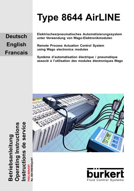
<strong>Type</strong> <strong>8644</strong> <strong>AirLINE</strong><br />
Elektrisches/pneumatisches Automatisierungssystem<br />
unter Verwendung von Wago-Elektronikmodulen<br />
Remote Process Actuation Control System<br />
using Wago electronics modules<br />
Système d’automatisation électrique / pneumatique<br />
associé à l’utilisation des modules électroniques Wago<br />
Fluid Control Systems
Inhaltsverzeichnis der Gesamtbedienungsanleitung<br />
Typ <strong>8644</strong> <strong>AirLINE</strong><br />
Elektrisches und pneumatisches Automatisierungssystem<br />
Typ <strong>8644</strong>/Betriebsanleitung-Nr. 804 090 - ind00/jan01<br />
INHALT<br />
ALLGEMEINE HINWEISE ........................................................................... AH 1<br />
SICHERHEITSHINWEISE ........................................................................................ AH 2<br />
Schutz gegen Beschädigung durch elektrostatische Aufladung....................... AH 2<br />
Darstellungsmittel ............................................................................................. AH 2<br />
LIEFERUMFANG ...................................................................................................... AH 3<br />
GARANTIEBESTIMMUNGEN .................................................................................. AH 3<br />
SYSTEMBESCHREIBUNG BÜRKERT-<strong>AirLINE</strong>-SYSTEM ......................... SB 1<br />
MODULARES ELEKTRISCHES/PNEUMATISCHES AUTOMATISIERUNGS-<br />
SYSTEM ................................................................................................................. SB 2<br />
AUFBAU DES PNEUMATIKBLOCKS ...................................................................... SB 3<br />
Aufbau der Einspeisungen ............................................................................... SB 5<br />
Aufbau der Ventilscheiben ............................................................................... SB 7<br />
Elektronik-Grundmodul 2fach Typ ME02.......................................................... SB 9<br />
Pneumatik-Grundmodul 2fach Typ MP11....................................................... SB 10<br />
Ventile ............................................................................................................. SB 11<br />
TECHNISCHE DATEN DES PNEUMATIKBLOCKS .............................................. SB 13<br />
IV 1<br />
deutsch
deutsch<br />
INHALT<br />
BESCHREIBUNG DES GESAMTSYSTEMS BÜRKERT - WAGO .............SW 1<br />
AUFBAU DES WAGO I/O-SYSTEM - 750 ................................................................SW 2<br />
ANSCHLUSSMODULE, PNEUMATISCH - LINKS TYP ME02 ................................SW 3<br />
Varianten ..........................................................................................................SW 3<br />
Technische Daten .............................................................................................SW 4<br />
Leistungsmerkmale aus der Sicht des Gesamtsystems ...................................SW 4<br />
ANSCHLUSSMODULE, PNEUMATISCH - MITTE TYP ME02 ................................SW 5<br />
Varianten ..........................................................................................................SW 5<br />
Technische Daten .............................................................................................SW 6<br />
Leistungsmerkmale aus der Sicht des Gesamtsystems ...................................SW 6<br />
ANSCHLUSSMODULE, PNEUMATISCH - RECHTS TYP ME02 ............................SW 7<br />
Varianten ..........................................................................................................SW 7<br />
Technische Daten .............................................................................................SW 8<br />
Leistungsmerkmale aus der Sicht des Gesamtsystems ...................................SW 8<br />
INSTALLATION.............................................................................................. IN 1<br />
SCHRITTE ZUR INSTALLATION DER VENTILINSEL .............................................. IN 2<br />
ENTFERNEN DER TRANSPORTSICHERUNG ......................................................... IN 3<br />
EINBAU DES <strong>AirLINE</strong>-SYSTEMS.............................................................................. IN 4<br />
FLUIDISCHE INSTALLATION .................................................................................... IN 5<br />
BESCHRIFTUNG DER ANSCHLÜSSE ..................................................................... IN 8<br />
INBETRIEBNAHME ....................................................................................... IB 1<br />
MASSNAHMEN VOR DER FLUIDISCHEN INBETRIEBNAHME .............................. IB 2<br />
FLUIDISCHE INBETRIEBNAHME ............................................................................. IB 2<br />
WARTUNG, FEHLERBEHEBUNG .............................................................. WF 1<br />
STÖRUNGSBESEITIGUNG ..................................................................................... WF 2<br />
IV 2 Typ <strong>8644</strong>/Betriebsanleitung-Nr. 804 090 - ind00/jan01
Typ <strong>8644</strong><br />
ALLGEMEINE<br />
HINWEISE<br />
ALLGEMEINE HINWEISE<br />
DARSTELLUNGSMITTEL ............................................................................................... AH 2<br />
ALLGEMEINE SICHERHEITSHINWEISE ....................................................................... AH 2<br />
Schutz gegen Beschädigung durch elektrostatische Aufladung ......................................................AH 2<br />
Sicherheitshinweise für das Ventil .....................................................................................................AH 3<br />
LIEFERUMFANG.............................................................................................................. AH 4<br />
GARANTIEBESTIMMUNGEN ......................................................................................... AH 4<br />
AH 1<br />
deutsch
deutsch<br />
ALLGEMEINE HINWEISE<br />
DARSTELLUNGSMITTEL<br />
In dieser Betriebsanleitung werden folgende Darstellungsmittel verwendet:<br />
markiert einen Arbeitsschritt, den Sie ausführen müssen<br />
ACHTUNG!<br />
ALLGEMEINE SICHERHEITSHINWEISE<br />
Beachten Sie die Hinweise dieser Betriebsanleitung sowie die Einsatzbedingungen und zulässigen Daten<br />
gemäß Datenblatt, damit das Gerät einwandfrei funktioniert und lange einsatzfähig bleibt:<br />
• Halten Sie sich bei der Einsatzplanung und dem Betrieb des Gerätes an die allgemeinen Regeln der Technik!<br />
• Installation und Wartungsarbeiten dürfen nur durch Fachpersonal und mit geeignetem Werkzeug erfolgen!<br />
• Beachten Sie die geltenden Unfallverhütungs- und Sicherheitsbestimmungen für elektrische Geräte während<br />
des Betriebs, der Wartung und der Reparatur des Gerätes!<br />
• Schalten Sie vor Eingriffen in das System in jedem Fall die Spannung ab!<br />
• Beachten Sie, dass in Systemen, die unter Druck stehen, Leitungen und Ventile nicht gelöst werden dürfen!<br />
• Treffen Sie geeignete Maßnahmen, um unbeabsichtigtes Betätigen oder unzulässige Beeinträchtigung auszuschließen!<br />
• Gewährleisten Sie nach einer Unterbrechung der elektrischen oder pneumatischen Versorgung einen definierten<br />
und kontrollierten Wiederanlauf des Prozesses!<br />
• Bei Nichtbeachtung dieser Hinweise und unzulässigen Eingriffen in das Gerät entfällt jegliche Haftung unsererseits,<br />
ebenso erlischt die Garantie auf Geräte und Zubehörteile!<br />
Schutz gegen Beschädigung durch elektrostatische Aufladung<br />
ACHTUNG<br />
VORSICHT BEI HANDHABUNG !<br />
ELEKTROSTATISCH<br />
GEFÄHRDETE<br />
BAUELEMENTE / BAUGRUPPEN<br />
kennzeichnet Hinweise, bei deren Nichtbeachtung Ihre Gesundheit oder die Funktionsfähigkeit<br />
des Gerätes gefährdet ist<br />
HINWEIS kennzeichnet wichtige Zusatzinformationen, Tips und Empfehlungen<br />
Das Gerät enthält elektronische Bauelemente, die gegen elektrostatische<br />
Entladung (ESD) empfindlich reagieren. Berührung mit elektrostatisch aufgeladenen<br />
Personen oder Gegenständen gefährdet diese Bauelemente. Im<br />
schlimmsten Fall werden sie sofort zerstört oder fallen nach der Inbetriebnahme<br />
aus.<br />
Beachten Sie die Anforderungen nach EN 100 015 - 1, um die Möglichkeit<br />
eines Schadens durch schlagartige elektrostatische Entladung zu minimieren<br />
bzw. zu vermeiden. Achten Sie ebenso darauf, dass Sie elektronische<br />
Bauelemente nicht bei anliegender Versorgungsspannung berühren.<br />
AH 2 Betriebsanleitung-Nr. 804 090
Sicherheitshinweise für das Ventil<br />
Typ <strong>8644</strong><br />
ACHTUNG!<br />
ALLGEMEINE HINWEISE<br />
• Halten Sie sich bei Einsatzplanung und Betrieb des Gerätes an die einschlägigen allgemein<br />
anerkannten sicherheitstechnischen Regeln.<br />
• Treffen Sie geeignete Maßnahmen, um unbeabsichtigtes Betätigen oder unzulässige Beeinträchtigungen<br />
auszuschließen.<br />
• Beachten Sie, dass in Systemen, die unter Druck stehen, Leitungen und Ventile nicht<br />
gelöst werden dürfen.<br />
0 bar, psi,<br />
kPa<br />
• Schalten Sie vor Eingriffen in das System in jedem Fall die Spannung ab!<br />
• Führen Sie die Druckversorgung möglichst großvolumig aus, um Druckabfall beim Schalten<br />
zu vermeiden!.<br />
• Das Gerät darf nur mit Gleichstrom betrieben werden!<br />
• Verletzungsgefahr!<br />
Bei Dauerbetrieb kann die Spule sehr heiss werden!<br />
AH 3<br />
deutsch
deutsch<br />
ALLGEMEINE HINWEISE<br />
LIEFERUMFANG<br />
Überzeugen Sie sich unmittelbar nach Erhalt der Sendung, dass der Inhalt nicht beschädigt ist und mit dem auf<br />
dem beigelegten Packzettel angegebenen Lieferumfang übereinstimmt.<br />
Bei Unstimmigkeiten wenden Sie sich bitte umgehend an unseren Kundenservice:<br />
oder an Ihre Bürkert-Niederlassung.<br />
GARANTIEBESTIMMUNGEN<br />
Diese Druckschrift enthält keine Garantiezusagen. Wir verweisen hierzu auf unsere allgemeinen Verkaufs- und<br />
Geschäftsbedingungen. Voraussetzung für die Garantie ist der bestimmungsgemäße Gebrauch des Gerätes unter<br />
Beachtung der spezifizierten Einsatzbedingungen.<br />
ACHTUNG!<br />
Bürkert Steuer- und Regelungstechnik<br />
Chr.-Bürkert-Str. 13-17<br />
Service-Abteilung<br />
D-76453 Ingelfingen<br />
Tel.: (07940) 10-586<br />
Fax: (07940) 10-428<br />
E-mail: service@buerkert.com<br />
Die Gewährleistung erstreckt sich nur auf die Fehlerfreiheit des gelieferten Automatisierungssystems<br />
und der angebauten Ventile. Es wird jedoch keine Haftung übernommen für Folgeschäden<br />
jeglicher Art, die durch Ausfall oder Fehlfunktion des Gerätes entstehen könnten.<br />
AH 4 Betriebsanleitung-Nr. 804 090
Typ <strong>8644</strong><br />
SYSTEMBESCHREIBUNG BÜRKERT <strong>AirLINE</strong>-SYSTEM<br />
SYSTEM-<br />
BESCHREIBUNG<br />
BÜRKERT<br />
<strong>AirLINE</strong>-SYSTEM<br />
MODULARES ELEKTRISCHES/PNEUMATISCHES AUTOMATISIERUNGSSYSTEM .. SB 2<br />
AUFBAU DES PNEUMATIKBLOCKS .............................................................................. SB 3<br />
Aufbau der Einspeisungen..................................................................................................................SB 5<br />
Ventilscheiben .....................................................................................................................................SB 7<br />
Elektronik-Grundmodul 2fach Typ ME02 ............................................................................................SB 9<br />
Pneumatik-Grundmodul 2fach Typ MP11......................................................................................... SB 10<br />
Ventile ................................................................................................................................................ SB 11<br />
TECHNISCHE DATEN DES PNEUMATIKBLOCKS....................................................... SB 13<br />
SB 1<br />
deutsch
deutsch<br />
SYSTEMBESCHREIBUNG BÜRKERT <strong>AirLINE</strong>-SYSTEM<br />
MODULARES ELEKTRISCHES/PNEUMATISCHES AUTOMATISIERUNGS-<br />
SYSTEM TYP <strong>8644</strong> <strong>AirLINE</strong><br />
Typ <strong>8644</strong> <strong>AirLINE</strong> ist ein elektrisches und pneumatisches Automatisierungssystem, das für den Einsatz<br />
im Schaltschrank oder Schaltkasten optimiert wurde. In einem durchgängigen System sind alle elektronischen<br />
und pneumatischen Komponenten vereinheitlicht, so dass unter Beachtung einfacher Regeln<br />
pneumatische, elektrische und elektronische Module unterschiedlicher Funktionalität sehr einfach miteinander<br />
kombiniert werden können. Alle Komponenten werden durch einen Rastmechanismus verbunden.<br />
Dabei werden auch die erforderlichen elektrischen Verbindungen hergestellt. So lassen sich beispielsweise<br />
Ventile und Leistungsausgänge mit nur einer Feldbusanschaltung kombinieren. Eine Vielzahl von elektrischen<br />
Modulen (Klemmen) lassen sich sehr einfach mit den auf spezielle Pneumatikmodule (Ventilscheiben)<br />
gerasteten Ventilen kombinieren.<br />
Merkmale<br />
Charakteristische Merkmale von <strong>AirLINE</strong> sind:<br />
• einfache Handhabung<br />
• Funktionsblockorientierter Aufbau des Schaltkastens bzw. -schrankes<br />
• Automatischer Aufbau von Potentialgruppen, Strom-, Daten- und Sicherheitskreisen<br />
• Offene, flexible und modulare Struktur<br />
• Ventilscheiben und Klemmen mit 2er Breite: Diese erlauben eine optimale Anpassung an die Sollkonfiguration.<br />
Sie ermöglichen einen flexiblen und platzoptimierten Stationsaufbau ohne unnötige<br />
Reserveinstallation.<br />
• Ventilscheiben und Klemmen mit 8er Breite: Diese ermöglichen bei größeren Stationen einen schnellen<br />
und effektiven Stationsaufbau.<br />
• Kombination der Ventilscheiben- und Klemmenbreiten für einen zeit-, platz- und preisoptimierten Stationsaufbau<br />
Vorteile<br />
Dieses Prinzip bringt folgende Vorteile:<br />
• Strömungsoptimierter Ventilaufbau<br />
Durchfluss von ca. 300 Nl/min bei einer Ventilbreite von 10 mm<br />
• Integration von Rückschlagventilen im pneumatischem Grundmodul (optional)<br />
• Hohe Lebensdauer durch Wippentechnologie bei geölter und ungeölter Luft<br />
• Einfache Konfigurierbarkeit und Erweiterbarkeit durch hohe Modularität<br />
• Zahlreiche Ventilfunktionen: 3/2-, 5/2-Wege-Funktionen<br />
• Mechanische Hand-Not-Betätigung<br />
• Unterschiedliche Druckstufen in einer Verkettung möglich<br />
• Integration von Drucksensoren, Druckschaltern und Filterelementen<br />
• Zentrale Druckluftversorgung über Anschlussmodule beidseitig, sowie Zwischeneinspeisung möglich<br />
SB 2 Betriebsanleitung-Nr. 804 090
MERKMALE DES AUFBAUS<br />
Pneumatische<br />
Einspeisung links<br />
Typ <strong>8644</strong><br />
Manometer zur Betriebsdruckanzeige<br />
an der Station<br />
Arbeitsanschlüsse<br />
Versorgungs- und<br />
Entlüftungsanschlüsse<br />
8fach-Ventilscheibe<br />
SYSTEMBESCHREIBUNG BÜRKERT <strong>AirLINE</strong>-SYSTEM<br />
Zwischeneinspeisung<br />
Arbeitsanschlüsse<br />
2fach-Ventilscheibe<br />
Pneumatische Einspeisung<br />
rechts<br />
Versorgungs- und<br />
Entlüftungsanschlüsse<br />
SB 3<br />
deutsch
deutsch<br />
SYSTEMBESCHREIBUNG BÜRKERT <strong>AirLINE</strong>-SYSTEM<br />
AUFBAU DES PNEUMATIKBLOCKS<br />
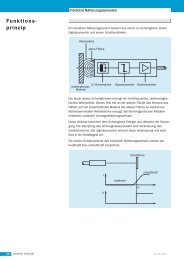
Der Pneumatikblock setzt sich aus folgenden Baugruppen zusammen:<br />
• Einspeisungen: Sammelanschlüsse für Versorgung, Abluft und Steuerhilfsluft<br />
• Ventilscheiben: Arbeitsanschlüsse<br />
Beispiel eines Pneumatikblocks, schematisch<br />
Elektrisch bildet das pneumatische Automatisierungssystem nach aussen eine abgeschlossene Einheit.<br />
Durch den modularen Aufbau kann die Anzahl der internen Busteilnehmer sowie Stromaufnahme des<br />
Pneumatikblocks variieren. Nach aussen stellt der Pneumatikblock wie jedes elektrische Modul / Klemme<br />
eine standardisierte elektrische Schnittstelle zur Verfügung.<br />
Einspeisungen<br />
Einspeisungen in Form pneumatischer Anschlussmodule bilden die fluidische Schnittstelle zwischen Versorgungsleitung<br />
und interner Versorgungsstruktur. Dabei wird das Fluid über die Einspeisung von einer<br />
Ventilscheibe an die nächste weitergegeben. Damit der Versorgungsdruck über die gesamte Strecke<br />
nahezu konstant bleibt, können weitere Einspeisungen erforderlich sein. Durch die Nutzung von Mitteleinspeisungen<br />
können auch Segmente aufgebaut werden, wenn die Versorgungsdurchgänge zwischen<br />
einzelnen Ventilscheiben verschlossen werden.<br />
elektrische<br />
1:1-Rangierung<br />
SB 4 Betriebsanleitung-Nr. 804 090
Typ <strong>8644</strong><br />
Aufbau der Einspeisungen<br />
2<br />
5<br />
8 + 9<br />
10<br />
11<br />
7<br />
Nr Bezeichnung Beschreibung<br />
SYSTEMBESCHREIBUNG BÜRKERT <strong>AirLINE</strong>-SYSTEM<br />
3<br />
1 Pneumatisches<br />
Anschlussmodul Typ MP11 (links, mitte, rechts)<br />
2 Elektrisches Umsetzmodul Typ ME02 (links,rechts)<br />
Schnittstelle zu elektrischem Teil des Automatisierungssystem<br />
(Feldbusknoten; elektrische Module / Klemmen)<br />
3 Blende Bestückungsvariante mit Manometer<br />
4 Rangierung (links Buchse, rechts Stecker)<br />
Elektrische Schnittstelle zur Datenrangierung innerhalb des<br />
Bürkert <strong>AirLINE</strong> – Systems Typ <strong>8644</strong><br />
5 Abdeckplatte<br />
6 Rasthaken Mechanische Befestigung für pneumatische Grundmodule MP11<br />
7 X Vorsteuerabluft- / Steuerhilfsluft-Anschluss<br />
8 (R) 3 Abluft - Anschluss<br />
9 (S) 5 Abluft - Anschluss<br />
10 (P) 1 Druckversorgung – Anschluss<br />
11 Schrauben Befestigungsschrauben für Schienenmontage<br />
12 Klemmstücke Befestigungsklemmstücke für Schienenmontage<br />
1<br />
4<br />
6<br />
(7)<br />
12<br />
(8)<br />
(10)<br />
(9)<br />
SB 5<br />
deutsch
deutsch<br />
SYSTEMBESCHREIBUNG BÜRKERT <strong>AirLINE</strong>-SYSTEM<br />
Varianten<br />
Die Einspeisungen wurden in verschiedenen Varianten konzipiert, um unterschiedlichen Anforderungen<br />
Rechnung zu tragen. So bietet das variable elektrische Anschlussmodul der Seiteneinspeisungen die Möglichkeit,<br />
das Pneumatiksystem mit elektrischen Systemen verschiedener Hersteller zu verwenden.<br />
Zur einfachen Inbetriebnahme und Diagnose sind Einspeisungen mit Manometer lieferbar. Die<br />
fluidischen Anschlüsse erhalten Sie mit geraden oder konischen Schraubanschlüssen sowie mit Schnellstecksystemen.<br />
Für spezielle Funktionen können die fluidischen Anschlüsse unterschiedlich belegt werden.<br />
Z. B. kann der Entlüftungsanschluss für das Vorsteuerventil als Anschluss für die Steuerhilfsluft genutzt<br />
werden, wobei zur Versorgung und zum Steuern des Ventils unterschiedliche Drücke angelegt werden<br />
können.<br />
Die Einspeisungen unterscheiden sich z. B. durch<br />
Manometer analoges Manometer oder kein Manometer<br />
Anschlussausführung G ¼, D 10, NPT ¼<br />
Elektrische Schnittstelle spezifisch, je nach Partner<br />
Steuerhilfsluft Ja/Nein<br />
SB 6 Betriebsanleitung-Nr. 804 090
Ventilscheiben<br />
Typ <strong>8644</strong><br />
SYSTEMBESCHREIBUNG BÜRKERT <strong>AirLINE</strong>-SYSTEM<br />
Ventilscheiben sind pneumatische Baugruppen, die mit den elektrischen Klemmen / Modulen vergleichbar<br />
sind.<br />
Als passive Busteilnehmer integrieren (und kombinieren) sie die Funktion von digitalem Ausgang in<br />
pneumatischer Ausführung. Die Ventilscheiben werden durch Kanäle im pneumatischen Block mit Fluid<br />
versorgt. Bei Ansteuerung der Ventile wird über Stichkanäle das Fluid auf die Arbeitsanschlüsse geschaltet.<br />
Die Entlüftung erfolgt über die Sammelanschlüsse an den Einspeisemodulen.<br />
Zweckmäßig sind mehrere Ventilscheiben in einem Gehäuse integriert. Derzeit sind 2-fach- und 8-fach-<br />
Ausführungen erhältlich.<br />
Aufbau der Ventilscheiben<br />
Durch den modularen Aufbau der Ventilscheiben ergibt sich eine Vielzahl von Varianten. Die Ventilscheiben<br />
bestehen aus:<br />
Elektronik-Grundmodulen<br />
Pneumatik-Grundmodulen<br />
Ventilen<br />
Ventile<br />
Pneumatik-<br />
Grundmodul<br />
Arbeitsanschlüsse<br />
Beschriftungsfläche<br />
Elektronik-<br />
Grundmodul<br />
SB 7<br />
deutsch
deutsch<br />
SYSTEMBESCHREIBUNG BÜRKERT <strong>AirLINE</strong>-SYSTEM<br />
Varianten<br />
Die Varianten unterscheiden sich z. B. durch<br />
Ventiltypen 6524, 6525<br />
Anschlussausführung D 6, M 5, M 7<br />
Rückschlagventile ohne, R, R + S<br />
SB 8 Betriebsanleitung-Nr. 804 090
Elektronik-Grundmodul 2fach Typ ME02<br />
Typ <strong>8644</strong><br />
Allgemeine Beschreibung<br />
SYSTEMBESCHREIBUNG BÜRKERT <strong>AirLINE</strong>-SYSTEM<br />
Das Elektronik-Grundmodul integriert die elektrischen Funktionen einer Ventilscheibe.<br />
Hierzu gehört vor allem die Ansteuerung der Ventile, sowie die Kommunikation mit dem Feldbusknoten.<br />
Zentrale<br />
Steuerung<br />
Innerhalb des <strong>AirLINE</strong>-Systems stellt das elektronische Grundmodul einen passiven Busteilnehmer dar.<br />
Ist das Buerkert-<strong>AirLINE</strong> System Typ <strong>8644</strong> mit dem elektronischen System anderer Hersteller gekoppelt,<br />
so sind die elektronischen Grundmodule und damit die pneumatischen Scheiben analog zu elektrischen<br />
Klemmen / Modulen zu betrachten. Die entsprechende Konfiguration wird in der Steuerdatei hinterlegt.<br />
Ein Zusammenfassen der pneumatischen Scheiben bis maximal 8fach-Blöcken ist möglich.<br />
Varianten<br />
Feldbusknoten Gateway 1 1<br />
Feldbusknoten Gateway 2 2<br />
Feldbusknoten Gateway ... ...<br />
Feldbusknoten Gateway n n<br />
Dezentrale Automatisierungseinheit<br />
passive Busteilnehmer Busteilnehmer,<br />
z. B. pneum. Grund-<br />
passive Busteilnehmer Busteilnehmer,<br />
z. B. pneum. Grundmodulmodul<br />
Neben der Zusammenfassung mehrerer Ventilausgänge zu 2fach- und 8fach-Blöcken, ergeben sich weitere<br />
Varianten durch unterschiedliche Ansteuerungsmöglichkeiten. Hierzu zählen die monostabilen<br />
Ventilausgänge (VA) und die Impulsausgänge(IA).<br />
SB 9<br />
deutsch
deutsch<br />
SYSTEMBESCHREIBUNG BÜRKERT <strong>AirLINE</strong>-SYSTEM<br />
Pneumatik-Grundmodul 2fach Typ MP11<br />
Allgemeine Beschreibung<br />
Das Pneumatik-Grundmodul integriert die pneumatischen Funktionen einer Ventilscheibe.<br />
Hierzu gehört vor allem die Versorgung der Ventile mit dem zu schaltenden Fluid über ein inneres Kanalsystem.<br />
Durch Verrasten lassen sich mehrere pneumatische Grundmodule aneinanderreihen. Die Abdichtung<br />
nach aussen bleibt dabei gewährleistet.<br />
Varianten<br />
Ventiltypen<br />
Sowohl 3/2-Wege- als auch 5/2-Wege-Ventile lassen sich problemlos mit den pneumatischen Grundmodulen<br />
kombinieren, da je Ventil zwei Arbeitsanschlüsse zur Verfügung gestellt werden.<br />
Arbeitsanschlüsse<br />
Hinzu kommen verschiedene Ausführungen für die Arbeitsanschlüsse. Wahlweise können Steckanschlüsse<br />
6mm (D6) oder Gewindeanschlüsse mit M5 oder M7 gewählt werden.<br />
Rückschlagventil<br />
Da bei bestimmten Anwendungen eine Funktionalität mit Rückschlagventilen gefordert wird, kann auch<br />
diese im pneumatischen Grundmodul integriert werden.<br />
SB 10 Betriebsanleitung-Nr. 804 090
Ventile<br />
Typ <strong>8644</strong><br />
Ventil Typ 6524<br />
3/2-Wege-Ventil<br />
Allgemeine Beschreibung<br />
SYSTEMBESCHREIBUNG BÜRKERT <strong>AirLINE</strong>-SYSTEM<br />
Ventil Typ 6525<br />
5/2-Wege-Ventil<br />
Automatisierungssysteme finden zunehmend Einsatz in allen Bereichen wo Steuerungs- und<br />
Regelungsaufgaben zu bewältigen sind.<br />
Die Ventile bilden dabei die Schnittstelle zwischen der Elektronik und Pneumatik.<br />
Die Ventile vom Typ 6524 und 6525 bestehen aus einem Vorsteuer-Wippenmagnetventil vom Typ 6104<br />
und einem Pneumatiksitzventil. Vorsteuerventil und Gehäuse sind miteinander verklammert. Das Wirkprinzip<br />
erlaubt das Schalten hoher Drücke bei geringer Leistungsaufnahme und mit kurzen Schaltzeiten.<br />
Die Ventile arbeiten wartungsfrei.<br />
SB 11<br />
deutsch
deutsch<br />
SYSTEMBESCHREIBUNG BÜRKERT <strong>AirLINE</strong>-SYSTEM<br />
Varianten<br />
Mit dem elektrisch – pneumatischem Automatisierungssystem <strong>AirLINE</strong> Typ <strong>8644</strong> werden Ventile mit folgenden<br />
Wirkungsweisen zur Verfügung gestellt:<br />
Ventile Wirkungsweise Betrieb Breite Typ<br />
3/2 – Wege C (NC) interne Steuerluft 10 mm 6524<br />
3/2 – Wege D (NO) Standard 10 mm 6524<br />
3/2 – Wege C (NC) Steuerhilfsluft 10 mm 6524<br />
3/2 – Wege D (NO) Steuerhilfsluft 10 mm 6524<br />
3/2 – Wege C - Vakuum (NC) Steuerhilfsluft 10 mm 8624<br />
5/2 – Wege H Standard 10 mm 6525<br />
5/2 – Wege H Steuerhilfsluft 10 mm 6525<br />
Technische Daten der Ventile Typ 6524 / 6525<br />
Gehäusewerkstoff PA (Polyamid) Betriebsspannung 24 V DC<br />
Dichtwerkstoffe FPM , NBR und PUR Spannungstoleranz ± 10%<br />
Medien Druckluft geölt, ölfrei, Nennleistung 1 W<br />
trocken; Nennbetriebsart Dauerbetrieb (100% ED)<br />
neutrale Gase Elektr. Anschluss Rechteckstecker mit<br />
Medientemperatur -10 bis +50 °C am Ventil Raster 5,08 mm<br />
Umgebungstemp. -10 bis +55 °C auf Ventilinsel integrierte Steckerbuchse<br />
Leitungsanschluss Flansch auf Ventilblock Rechtecksteckverbinder<br />
Pneumatikmodule MP11 Schutzart IP 40 mit Rechtecksteck-<br />
Versorg.-Anschluss G 1/4, NPT 1/4, verbinder<br />
1 (P), 3 (R), 5 (S) Steckkupplung Einbaulage beliebig, vorzugsweise<br />
Ø 10 mm Antrieb nach oben<br />
Arbeitsanschluss Steckkupplung Handbetätigung serienmäßig<br />
2 (A), 4 (B) Ø 6 mm, M5, M7 Schutzklasse 3 nach VDE 0580<br />
Durchfluss [Q Nn ]: Luft 300 l/min Schaltzeiten [ms]<br />
Messung am Ventilausgang bei 6 bar und +20 °C<br />
Öffnen Druckaufbau 0 bis 90%<br />
Schliessen Druckabbau 100 bis 10%<br />
Wirkungsweisen<br />
C 3/2-Wege-Ventil, vorgesteuert,<br />
stromlos Ausgang 1 gesperrt<br />
D 3/2-Wege-Ventil, vorgesteuert,<br />
stromlos Ausgang 2 druckbeaufschlagt<br />
H 5/2-Wege-Ventil, vorgesteuert,<br />
stromlos Ausgang 2 druckbeaufschlagt,<br />
Ausgang 4 entlüftet<br />
SB 12 Betriebsanleitung-Nr. 804 090
TECHNISCHE DATEN DES PNEUMATIKBLOCKS<br />
(Unter Verwendung von Elektronikmodulen und Ventiltypen 6524/6525)<br />
Typ <strong>8644</strong><br />
Spezifische Daten<br />
Ventiltypen Typ 6524, Typ 6525<br />
Anreihmass 11 mm<br />
Durchfluss [Q Nn ] 300 l/min<br />
Druckbereich 2,5 - 7 bar<br />
Betriebsspannung 24 V/DC<br />
Nennleistung 1 W<br />
Nennstrom je Ventil 42 mA<br />
Pneumatik-Module Ventilscheiben 2- und 8-fach<br />
Elektrische Module 2- und 8-fach<br />
Allgemeine Daten für den elektrischen Anschluss<br />
Zul. Betriebs- und Umgebungstemperatur 0 bis +55 °C<br />
Zul. Lagertemperatur - 20 bis +60 °C<br />
Betriebsspannung 24 V/DC<br />
Spannungstoleranz ±10%<br />
Restwelligkeit 1 V ss (bei Feldbus)<br />
Schutzklasse 3 nach VDE 0580<br />
SYSTEMBESCHREIBUNG BÜRKERT <strong>AirLINE</strong>-SYSTEM<br />
Nennbetriebsart Dauerbetrieb, 100 % ED (Einschaltdauer)<br />
Gesamtstrom in Abhängigkeit von der elektrischen Anschlusstechnik<br />
SB 13<br />
deutsch
deutsch<br />
SYSTEMBESCHREIBUNG BÜRKERT <strong>AirLINE</strong>-SYSTEM<br />
SB 14 Betriebsanleitung-Nr. 804 090
Typ <strong>8644</strong><br />
BESCHREIBUNG GESAMTSYSTEM BÜRKERT - WAGO<br />
BESCHREIBUNG<br />
GESAMTSYSTEM<br />
BÜRKERT - WAGO<br />
AUFBAU DES SYSTEMS .................................................................................................SW 2<br />
ANSCHLUSSMODULE, PNEUMATISCH - LINKS TYP ME02 .........................................SW 3<br />
Varianten ........................................................................................................................................... SW 3<br />
Technische Daten .............................................................................................................................. SW 4<br />
Leistungsmerkmale aus der Sicht des Gesamtsystems ................................................................. SW 4<br />
ANSCHLUSSMODULE, PNEUMATISCH - MITTE TYP ME02 .........................................SW 5<br />
Varianten ........................................................................................................................................... SW 5<br />
Technische Daten .............................................................................................................................. SW 6<br />
Leistungsmerkmale aus der Sicht des Gesamtsystems ................................................................. SW 6<br />
ANSCHLUSSMODULE, PNEUMATISCH - RECHTS TYP ME02 .....................................SW 7<br />
Varianten ............................................................................................................................................ SW 7<br />
Technische Daten .............................................................................................................................. SW 8<br />
Leistungsmerkmale aus der Sicht des Gesamtsystems ................................................................. SW 8<br />
SW 1<br />
deutsch
deutsch<br />
BESCHREIBUNG GESAMTSYSTEM BÜRKERT - WAGO<br />
Aufbau des Systems<br />
Konfigurierungsbeispiel von Typ <strong>8644</strong> <strong>AirLINE</strong> mit Profibus-DP-Anschluss<br />
SW 2 Betriebsanleitung-Nr. 804 090
Typ <strong>8644</strong><br />
Elektrische Schnittstelle Bürkert/<br />
Elektr. Schnittstelle zu<br />
Wago I/O-System - 750 im<br />
Pneumatikblock Wago - Inline (<strong>AirLINE</strong>)<br />
Manometer<br />
Blende<br />
G ¼<br />
M 5<br />
G ¼<br />
D 10<br />
D 4<br />
D 10<br />
BESCHREIBUNG GESAMTSYSTEM BÜRKERT - WAGO<br />
ANSCHLUSSMODULE, PNEUMATISCH - LINKS TYP ME02<br />
Varianten<br />
Id.-Nr. Versorgungsanschluß (P) 1 X* Abluftanschluß (R/S) 3/5<br />
Variantenzeichnung<br />
ohne Manometer<br />
148844 G ¼ M5 G ¼<br />
150242 D 10 D 4 D 10<br />
148848 NPT ¼ M5 NPT ¼<br />
mit Manometer<br />
150144 G ¼ M5 G ¼<br />
150146 D 10 D 4 D 10<br />
150145 NPT ¼ M5 NPT ¼<br />
* Funktionen<br />
Betrieb Belegung von X<br />
Standard Abluft Vorsteuerventil<br />
Steuerhilfsluft Anschluß für Steuerhilfsluft<br />
(Für Betrieb mit Steuerhilfsluft sind spezielle Ventile notwendig)<br />
Seiteneinspeisung links<br />
NPT ¼<br />
M 5<br />
NPT ¼<br />
Pneumatische Anschlüsse<br />
Pneumatische<br />
Anschluesse<br />
SW 3<br />
deutsch
deutsch<br />
BESCHREIBUNG GESAMTSYSTEM BÜRKERT - WAGO<br />
Technische Daten<br />
Gehäusemaße (Breite x Höhe x Tiefe) 61,9 mm x 70,4 mm x 119 mm (inkl. Rasthaken)<br />
Gewicht 220 g<br />
Zulässige Temperatur (Betrieb) 0 °C bis 55 °C<br />
Zulässige Umgebungstemperatur 0 °C bis 55 °C<br />
Zulässige Temperatur (Lagerung / Transport) -20 °C bis +60 °C<br />
Zulässige Luftfeuchtigkeit (Betrieb) 75 % im Mittel, 85 % gelegentlich<br />
ACHTUNG!<br />
Zulässige Luftfeuchtigkeit (Betrieb) 75 % im Mittel, 85 % gelegentlich<br />
ACHTUNG!<br />
Treffen Sie im Bereich von 0°C bis 55 °C geeignete Maßnahmen gegen erhöhte Luftfeuchtigkeit<br />
(> 85 %).<br />
Eine leichte Betauung von kurzer Dauer darf gelegentlich am Aussengehäuse auftreten,<br />
z.B. wenn die Einspeisung von einem Fahrzeug in einen geschlossenen Raum gebracht<br />
wird.<br />
Zulässiger Luftdruck (Betrieb) 80 kPa bis 106 kPa (bis zu 2000 m üNN)<br />
Zulässiger Luftdruck (Lagerung / Transport) 70 kPa bis 106 kPa (bis zu 3000 m üNN)<br />
Schutzart IP 20 nach IEC 60529<br />
Schutzklasse Klasse 3 gemäß VDE 106, IEC 60536<br />
Leistungsmerkmale aus der Sicht des Gesamtsystems<br />
Die Seiteneinspeisung links ist kein Busteilnehmer, wodurch Adressen für diese Baugruppe entfallen.<br />
- logisch kein Prozessabbild, deshalb wird keine Adresse benötigt<br />
- mechanisch 47,5 mm Einbaumaß<br />
- elektrisch keine Stromaufnahme<br />
- fluidisch linke Begrenzung des Pneumatikblocks, linke Einspeisung<br />
SW 4 Betriebsanleitung-Nr. 804 090
Typ <strong>8644</strong><br />
Manometer Blende<br />
G ¼<br />
M 5<br />
G ¼<br />
D 10<br />
D 4<br />
D 10<br />
BESCHREIBUNG GESAMTSYSTEM BÜRKERT - WAGO<br />
ANSCHLUSSMODULE, PNEUMATISCH - MITTE TYP ME02<br />
Varianten<br />
Id.-Nr. Versorgungsanschluß (P) 1 X* Abluftanschluß (R/S) 3/5<br />
* Funktionen<br />
Betrieb Belegung von X<br />
Standard Abluft Vorsteuerventil<br />
Variantenzeichnung<br />
ohne Manometer<br />
150628 G ¼ M5 G ¼<br />
150629 D 10 D 4 D 10<br />
150630 NPT ¼ M5 NPT ¼<br />
mit Manometer<br />
150631 G ¼ M5 G ¼<br />
150632 D 10 D 4 D 10<br />
150633 NPT ¼ M5 NPT ¼<br />
Steuerhilfsluft Anschluß für Steuerhilfsluft<br />
(Für Betrieb mit Steuerhilfsluft sind spezielle Ventile notwendig)<br />
Mitteleinspeisung<br />
Elektrische Schnittstelle Bürkert/<br />
Elektr. Wago I/O-System Schnittstelle - 750 im<br />
kompatibel Pneumatikblock zu (<strong>AirLINE</strong>)<br />
Wago - Inline<br />
NPT ¼<br />
M5<br />
NPT ¼<br />
Pneumatische Anschlüsse<br />
Anschluesse<br />
SW 5<br />
deutsch
deutsch<br />
BESCHREIBUNG GESAMTSYSTEM BÜRKERT - WAGO<br />
Technische Daten<br />
Gehäusemaße (Breite x Höhe x Tiefe) 45,1 mm x 70,4 mm x 119 mm (inkl. Rasthaken)<br />
Gewicht 118 g<br />
Zulässige Temperatur (Betrieb) 0 °C bis 55 °C<br />
Zulässige Umgebungstemperatur 0 °C bis 55 °C<br />
Zulässige Temperatur (Lagerung / Transport) -20 °C bis +60 °C<br />
Zulässige Luftfeuchtigkeit (Betrieb) 75 % im Mittel, 85 % gelegentlich<br />
ACHTUNG!<br />
Zulässige Luftfeuchtigkeit (Betrieb) 75 % im Mittel, 85 % gelegentlich<br />
ACHTUNG!<br />
Treffen Sie im Bereich von 0°C bis 55 °C geeignete Maßnahmen gegen erhöhte Luftfeuchtigkeit<br />
(> 85 %).<br />
Eine leichte Betauung von kurzer Dauer darf gelegentlich am Aussengehäuse auftreten,<br />
z.B. wenn die Einspeisung von einem Fahrzeug in einen geschlossenen Raum gebracht<br />
wird.<br />
Zulässiger Luftdruck (Betrieb) 80 kPa bis 106 kPa (bis zu 2000 m üNN)<br />
Zulässiger Luftdruck (Lagerung / Transport) 70 kPa bis 106 kPa (bis zu 3000 m üNN)<br />
Schutzart IP 20 nach IEC 60529<br />
Schutzklasse Klasse 3 gemäß VDE 106, IEC 60536<br />
Leistungsmerkmale aus der Sicht des Gesamtsystems<br />
Die Mitteleinspeisung ist kein Busteilnehmer, wodurch Adressen für diese Baugruppe entfallen.<br />
- logisch kein Prozessabbild, deshalb wird keine Adresse benötigt<br />
- mechanisch 33 mm Anreihmaß<br />
- elektrisch keine Stromaufnahme<br />
- fluidisch zusätzliche Einspeisung<br />
SW 6 Betriebsanleitung-Nr. 804 090
Typ <strong>8644</strong><br />
Verwendung von<br />
Steuerhilfsluft<br />
Belegung von x ist<br />
unterschiedlich<br />
G 1/4<br />
M 5<br />
G 1/4<br />
BESCHREIBUNG GESAMTSYSTEM BÜRKERT - WAGO<br />
ANSCHLUSSMODULE, PNEUMATISCH - RECHTSTYP ME02<br />
Varianten<br />
Identnummer Versorgungsanschluß X* Abluftanschluß<br />
ohne Manometer<br />
150147 G ¼ M5 G ¼<br />
150149 D 10 D 4 D 10<br />
150148 NPT ¼ M5 NPT ¼<br />
Variantenzeichnung<br />
mit Manometer<br />
150150 G ¼ M5 G ¼<br />
150152 D 10 D 4 D 10<br />
150151 NPT ¼ M5 NPT ¼<br />
* Funktionen<br />
Betrieb Belegung von X<br />
Standard Abluft Vorsteuerventil<br />
Steuerhilfsluft Anschluß für Steuerhilfsluft<br />
(Für Betrieb mit Steuerhilfsluft sind spezielle Ventile notwendig)<br />
Seiteneinspeisung rechts<br />
Manometer Blende<br />
Manometer Blende<br />
D 10<br />
D 6<br />
D 10<br />
Elektrische Schnittstelle Elektr. Schnittstelle Bürkert/ zu<br />
Wago I/O-System Wago - 750 - imInline<br />
Pneumatikblock (<strong>AirLINE</strong>)<br />
NPT 1/4 1/4<br />
M 5<br />
NPT 1/4<br />
Pneumatische PneumatischeAns Anschlüsse<br />
chluesse<br />
SW 7<br />
deutsch
deutsch<br />
BESCHREIBUNG GESAMTSYSTEM BÜRKERT - WAGO<br />
Technische Daten<br />
Gehäusemaße (Breite x Höhe x Tiefe) 47,5 mm x 70,4 mm x 119 mm<br />
Gewicht 220 g<br />
Zulässige Temperatur (Betrieb) 0 °C bis 55 °C<br />
Zulässige Umgebungstemperatur 0 °C bis 55 °C<br />
Zulässige Temperatur (Lagerung / Transport) -20 °C bis +60 °C<br />
Zulässige Luftfeuchtigkeit (Betrieb) 75 % im Mittel, 85 % gelegentlich<br />
ACHTUNG!<br />
Zulässige Luftfeuchtigkeit (Betrieb) 75 % im Mittel, 85 % gelegentlich<br />
ACHTUNG!<br />
Treffen Sie im Bereich von 0°C bis 55 °C geeignete Maßnahmen gegen erhöhte Luftfeuchtigkeit<br />
(> 85 %).<br />
Eine leichte Betauung von kurzer Dauer darf gelegentlich am Außengehäuse auftreten,<br />
z.B. wenn die Einspeisung von einem Fahrzeug in einen geschlossenen Raum gebracht<br />
wird.<br />
Zulässiger Luftdruck (Betrieb) 80 kPa bis 106 kPa (bis zu 2000 m üNN)<br />
Zulässiger Luftdruck (Lagerung / Transport) 70 kPa bis 106 kPa (bis zu 3000 m üNN)<br />
Schutzart IP 20 nach IEC 60529<br />
Schutzklasse Klasse 3 gemäß VDE 106, IEC 60536<br />
Leistungsmerkmale aus der Sicht des Gesamtsystems<br />
Die Seiteneinspeisung rechts ist kein Busteilnehmer, wodurch Adressen für diese Baugruppe entfallen.<br />
- logisch kein Prozessabbild, deshalb wird keine Adresse benötigt<br />
- mechanisch 47,5 mm Einbaumaß<br />
- elektrisch keine Stromaufnahme<br />
- fluidisch rechte Begrenzung des Pneumatikblocks, rechte Einspeisung<br />
SW 8 Betriebsanleitung-Nr. 804 090
Typ <strong>8644</strong><br />
INSTALLATION<br />
INSTALLATION<br />
INSTALLATIONSANLEITUNG .......................................................................................... IN 2<br />
Schritte zur Installation der Ventilinsel ............................................................................................. IN 2<br />
Entfernen der Transportsicherung ..................................................................................................... IN 3<br />
Einbau des <strong>AirLINE</strong>-Systems .............................................................................................................. IN 4<br />
Fluidische Installation ........................................................................................................................ IN 5<br />
Beschriftung der Anschlüsse .............................................................................................................. IN 8<br />
IN 1<br />
english
english<br />
INSTALLATION<br />
INSTALLATIONSANLEITUNG<br />
Das <strong>AirLINE</strong>-System Typ <strong>8644</strong> kann mit elektrischen Automatisierungssystemen verschiedener Hersteller<br />
kombiniert werden. Beachten Sie bitte auch deren entsprechende Installationshinweise.<br />
ACHTUNG!<br />
Schalten Sie vor der Installation die Installationsumgebung spannungsfrei und sichern<br />
Sie diese gegen Einschalten.<br />
Schritte zur Installation der Ventilinsel<br />
Entfernen der Transportsicherung (Demontage der Module von der Normschiene)<br />
Einbau (z. B. im Schaltschrank)<br />
Fluidische Installation<br />
Beschriftung der Anschlüsse<br />
Elektrische Installation siehe "Beschreibung des Gesamtsystems Bürkert - Wago"<br />
IN 2 Betriebsanleitung-Nr. 804 090
Typ <strong>8644</strong><br />
Entfernen der Transportsicherung<br />
INSTALLATION<br />
Der Pneumatikblock ist fest auf der Normschiene verschraubt. An seinen Seiten können weitere elektrische<br />
Module / Klemmen befestigt sein.<br />
Falls vorhanden, lösen Sie die benachbarten Module<br />
/ Klemmen!<br />
Entriegeln Sie die Befestigung des Pneumatikblocks<br />
an der Normschiene. Drehen Sie hierzu<br />
die Befestigungsschrauben entgegengesetzt zum<br />
Uhrzeigersinn bis zum Anschlag.<br />
Heben Sie den Pneumatikblock senkrecht von der<br />
Normschiene ab.<br />
Lösen Sie entsprechend der Herstellerbeschreibung<br />
die restlichen Module / Klemmen von der<br />
Normschiene.<br />
Befestigungsschrauben<br />
Befestigungsschrauben<br />
IN 3<br />
english
english<br />
INSTALLATION<br />
Einbau des <strong>AirLINE</strong>-Systems (z. B. im Schaltschrank)<br />
ACHTUNG!<br />
Beachten Sie bei Arbeiten im Schaltschrank die entsprechenden Sicherheitsbestimmungen!<br />
Überprüfen Sie vor der Montage ob die Befestigungsschiene fest im Schaltschrank oder<br />
im System verankert ist.<br />
Beachten Sie bei der Reihenfolge des Einbaus die Vorgaben in der/den Konfigurationsdatei(en).<br />
Beachten Sie die Hinweise des angeschlossenen Systems!<br />
Rasten Sie entsprechend den Herstellerangaben alle elektrischen Module / Klemmen bis auf den Pneumatikblock<br />
auf die Normschiene.<br />
Schieben Sie entlang der Schnittstelle des Vorgängermoduls den Pneumatikblock auf die Normschiene.<br />
HINWEIS Alternative bei größeren Pneumatikblöcken:<br />
- entfernen Sie das Vorgängermodul<br />
- rasten Sie den Pneumatikblock auf die Normschiene<br />
- schieben sie den Block in seine Endlage<br />
- stecken Sie nun das Vorgängermodul wieder auf<br />
Schrauben Sie den Pneumatikblock an der Normschiene durch Anziehen der Befestigungsschrauben<br />
im Uhrzeigersinn fest.<br />
Montieren Sie alle weiteren Module / Klemmen auf der Normschiene<br />
Demontage<br />
Lösen Sie die Befestigungsschrauben. Drehen Sie hierzu die Befestigungsschrauben entgegengesetzt<br />
zum Uhrzeigersinn bis zum Anschlag.<br />
Entnehmen Sie den Block senkrecht zur Normschiene.<br />
IN 4 Betriebsanleitung-Nr. 804 090
Typ <strong>8644</strong><br />
Fluidische Installation<br />
Sicherheitshinweise<br />
ACHTUNG!<br />
Vorgehensweise<br />
INSTALLATION<br />
Die pneumatischen Anschlüsse dürfen bei der Installation nicht mit Druck beaufschlagt<br />
sein!<br />
Führen Sie die Anschlüsse möglichst großvolumig aus.<br />
Schließen Sie nicht benötigte, offene Anschlüsse mit Verschlussschrauben!<br />
Die Anschlüsse für die Vorsteuerabluft dürfen nicht verschlossen werden!<br />
Überprüfen Sie die vorschriftsmäßige Belegung der Anschlüsse 1 und 3 bzw.<br />
5, diese dürfen auf keinen Fall vertauscht werden!<br />
Pneumatischen Anschlüsse - Einspeisung<br />
(R/S) 3/5<br />
X<br />
(P) 1<br />
Stecken (D10) oder schrauben (G1/4, NPT 1/4) Sie die Anschlüsse je nach Ausführung an den entsprechenden<br />
Arbeitsanschlüssen ein.<br />
Hinweise zu Steckanschlüssen<br />
HINWEIS<br />
Für die Steckanschlüsse müssen die Schlauchleitungen folgende Anforderungen erfüllen:<br />
• Mindesthärte von 40 Shore D (nach DIN 53505 bzw. ISO 868);<br />
• Aussendurchmesser entsprechend DIN 73378 (max. zul. Abweichung ± 0,1 mm vom<br />
Nennmaß);<br />
• gratfrei, rechtwinklig abgeschnitten und am Aussendurchmesser unbeschädigt;<br />
• die Schlauchleitungen sind bis zum Anschlag in die Steckanschlüsse einzudrücken.<br />
Demontage der Steckanschlüsse<br />
Abluft Abluft<br />
Standardausführung: Entlüftung des Vorsteuerventils<br />
Steuerhilfsluftausführung: Entlüftung für Vorsteuerventil P-Anschluss / Steuerhilfsluft<br />
Druckversorgungsanschluss<br />
Versorgungsanschluß<br />
Drücken Sie zum Lösen der Leitungen den Druckring ein und ziehen Sie die Schlauchleitung heraus.<br />
IN 5<br />
english
english<br />
INSTALLATION<br />
Pneumatischen Anschlüsse - Ventilscheiben<br />
HINWEIS Bei 3/2 – Wege Ventilen bleiben die oberen Anschlüsse frei!<br />
5/2-Wege-Ventile<br />
3/2-Wege-Ventile<br />
Montage<br />
Varianten<br />
8 - fach<br />
8fach-Ventischeibe<br />
4 x 2 - fach<br />
4 x 2fach-Ventilscheiben<br />
Variante 1 Variante 2 Variante 3<br />
Arbeitsanschluß oben (2) M 5 M 7 D 6<br />
Arbeitsanschluß unten (4) M 5 M 7 D 6<br />
Variante 1 Variante 2 Variante 3<br />
Arbeitsanschlüsse<br />
bei 5/2-Wege-Ventilen<br />
Arbeitsanschlüsse<br />
bei 3/2-Wege-Ventilen<br />
Arbeitsanschluß oben (0) intern verschlossen intern verschlossen intern verschlossen<br />
Arbeitsanschluß unten (2) M 5 M 7 D 6<br />
Stecken (D 6) oder schrauben (M 5, M 7) Sie die Anschlüsse je nach Ausführung an den entsprechenden<br />
Arbeitsanschlüssen ein.<br />
Bei Gewindeausführungen können Anschlussnippel verwendet werden.<br />
IN 6 Betriebsanleitung-Nr. 804 090
Typ <strong>8644</strong><br />
Hinweise zu Steckanschlüssen<br />
HINWEIS<br />
INSTALLATION<br />
Für die Steckanschlüsse müssen die Schlauchleitungen folgende Anforderungen erfüllen:<br />
• Mindesthärte von 40 Shore D (nach DIN 53505 bzw. ISO 868);<br />
• Aussendurchmesser entsprechend DIN 73378 (max. zul. Abweichung ± 0,1 mm vom<br />
Nennmaß);<br />
• gratfrei, rechtwinklig abgeschnitten und am Aussendurchmesser unbeschädigt;<br />
• die Schlauchleitungen sind bis zum Anschlag in die Steckanschlüsse einzudrücken.<br />
Demontage der Steckanschlüsse<br />
Drücken Sie zum Lösen der Leitungen den Druckring ein und ziehen Sie die Schlauchleitung heraus.<br />
IN 7<br />
english
english<br />
INSTALLATION<br />
Beschriftung der Anschlüsse<br />
Beschriften Sie die Beschriftungsfelder mit<br />
den Daten der Ventilanschlüsse<br />
Beschriftungsfelder<br />
IN 8 Betriebsanleitung-Nr. 804 090
Typ <strong>8644</strong><br />
INBETRIEBNAHME<br />
INBETRIEBNAHME<br />
MASSNAHMEN VOR DER FLUIDISCHEN INBETRIEBNAHME ..................................... IB 1<br />
FLUIDISCHE INBETRIEBNAHME .................................................................................... IB 1<br />
IB 1<br />
deutsch
deutsch<br />
INBETRIEBNAHME<br />
Massnahmen vor der fluidischen Inbetriebnahme<br />
Überprüfen Sie Anschlüsse, Spannung und Betriebsdruck!<br />
Beachten Sie, dass max. Betriebsdaten (siehe <strong>Type</strong>nschild) nicht überschritten werden!<br />
Überprüfen Sie die vorschriftsmäßige Belegung der Anschlüsse 1 und 3 bzw. 5, diese dürfen auf keinen<br />
Fall vertauscht werden!<br />
Entriegeln Sie bei elektrischem Betrieb die Handbetätigung!<br />
Fluidische Inbetriebnahme<br />
Schalten Sie den Versorgungsdruck ein<br />
Schalten Sie erst danach die Spannung ein!<br />
IB 2 Betriebsanleitung-Nr. 804 090<br />
bar
Typ <strong>8644</strong><br />
WARTUNG<br />
UND<br />
WARTUNG UND FEHLERBEHEBUNG<br />
FEHLERBEHEBUNG<br />
STÖRUNGSBESEITIGUNG ............................................................................................. WF 2<br />
WF 1<br />
deutsch
deutsch<br />
WARTUNG UND FEHLERBEHEBUNG<br />
STÖRUNGSBESEITIGUNG<br />
Störung<br />
Ventile schalten nicht:<br />
Ventile schalten verzögert<br />
oder blasen an den Entlüftungsanschlüssen<br />
ab:<br />
undichte Ventilblöcke:<br />
Service-Adresse:<br />
Steuer- und Regelungstechnik<br />
Chr.-Bürkert-Str. 13-17<br />
Service-Abteilung<br />
D-76453 Ingelfingen<br />
Tel.: (07940) 10-586<br />
Fax: (07940) 10-428<br />
E-mail: service@buerkert.com<br />
mögliche Ursache<br />
oder Ihre Bürkert-Niederlassung (s. Rückseite)<br />
keine oder nicht ausreichende Betriebsspannung;<br />
Handbetätigung nicht in neutraler Stellung;<br />
Druckversorgung nicht ausreichend oder nicht<br />
vorhanden.<br />
Druckversorgung nicht ausreichend oder nicht<br />
vorhanden;<br />
Ventile sind während des Druckaufbaus nicht<br />
in Grundstellung (stromlos)<br />
keine ausreichende Entlüftung der Abluftkanäle<br />
durch zu kleine oder verschmutzte<br />
Geräuschdämpfer (Rückdrücke);<br />
Verunreinigungen bzw. Fremdkörper im Vorsteuer-<br />
oder Hauptventil.<br />
fehlende oder gequetschte O-Ringe zwischen<br />
den Modulen;<br />
fehlende oder falsch positionierte Profildichtungen<br />
zwischen Ventil und Grundplatte.<br />
Beseitigung<br />
Überprüfen Sie den elektrischen<br />
Anschluss.<br />
Stellen Sie die Betriebsspannung laut<br />
<strong>Type</strong>nschild sicher.<br />
Bringen Sie die Handbetätigung in Null-<br />
Stellung.<br />
Führen Sie die Druckversorgung möglichst<br />
großvolumig aus (auch bei vorgeschalteten<br />
Geräten wie Druckreglern,<br />
Wartungseinheiten, Absperrventilen<br />
usw.).<br />
Mindestbetriebsdruck ≥ 2,5 bar<br />
Führen Sie die Druckversorgung möglichst<br />
großvolumig aus (auch bei vorgeschalteten<br />
Geräten wie Druckreglern,<br />
Wartungseinheiten, Absperrventilen<br />
usw.).<br />
Mindestbetriebsdruck ≥ 2,5 bar<br />
Beaufschlagen Sie den Ventilblock mit<br />
Druck, bevor Sie die Ventile schalten!<br />
Verwenden Sie entsprechend groß<br />
dimensionierte Geräuschdämpfer bzw.<br />
Expansionsgefäße.<br />
Reinigen Sie verschmutzte Geräuschdämpfer.<br />
Beaufschlagen Sie die Abluftkanäle mit<br />
impulsartigem Druck, um die Verunreinigungen<br />
auszublasen; bauen Sie ein<br />
neues Vorsteuer- bzw. Hauptventil ein,<br />
wenn diese Maßnahme keinen Erfolg<br />
bringt.<br />
Ermitteln Sie die Leckstelle oder fehlende<br />
Dichtungen.<br />
Setzen Sie fehlende Dichtungen ein oder<br />
erneuern Sie beschädigte Dichtungen.<br />
WF 2 Betriebsanleitung-Nr. 804 090
List of contents of overall operating instructions for<br />
<strong>Type</strong> <strong>8644</strong> <strong>AirLINE</strong><br />
Remote Process Actuation Control System<br />
<strong>Type</strong> <strong>8644</strong> / Operating Instructions No. 804 090 - ind00/jan01<br />
CONTENTS<br />
GENERAL NOTES ...................................................................................... GN 1<br />
SYMBOLS..................................................................................................................... GN 2<br />
General safety notes .................................................................................................. GN 2<br />
Protection from damage by electrostatic charging ..................................................... GN 2<br />
Safety notes for the valve ........................................................................................... GN 3<br />
SCOPE OF DELIVERY ................................................................................................. GN 4<br />
WARRANTY CONDITIONS .......................................................................................... GN 4<br />
DESCRIPTION OF BÜRKERT <strong>AirLINE</strong>-SYSTEM .................................... BA 1<br />
MODULAR ELECTRICAL/PNEUMATIC AUTOMATION<br />
SYSTEM TYPE <strong>8644</strong> <strong>AirLINE</strong> ...................................................................................... BA 2<br />
COMPOSITION OF THE PNEUMATIC BLOCK ........................................................... BA 3<br />
Supply modules ......................................................................................................... BA 4<br />
Valve units ................................................................................................................. BA 7<br />
Basic electronic module, 2-fold, type ME02 ............................................................... BA 9<br />
Basic pneumatic module, 2-fold, type MP11 ............................................................ BA 10<br />
Valves ...................................................................................................................... BA 11<br />
TECHNICAL DATA OF THE PNEUMATIC BLOCK ................................................... BA 13<br />
LC I<br />
english
english<br />
CONTENTS<br />
DESCRIPTION OF OVERALL SYSTEM BÜRKERT - WAGO ................ WA 1<br />
LC II<br />
COMPOSITION OF THE SYSTEM...............................................................................WA 2<br />
CONNECTOR MODULES, PNEUMATIC, LEFT, TYPE ME02 .....................................WA 3<br />
Variants ................................................................................................................ WA 3<br />
Technical data .......................................................................................................... WA 4<br />
Performance characteristics seen from the overall system ..................................... WA 4<br />
CONNECTOR MODULES, PNEUMATIC, MIDDLE, TYPE ME02 ................................WA 5<br />
Variants ................................................................................................................ WA 5<br />
Technical data .......................................................................................................... WA 6<br />
Performance characteristics seen from the overall system ..................................... WA 6<br />
CONNECTOR MODULES, PNEUMATIC, RIGHT, TYPE ME02 ...................................WA 7<br />
Variants ................................................................................................................ WA 7<br />
Technical data .......................................................................................................... WA 8<br />
Performance characteristics seen from the overall system ..................................... WA 8<br />
INSTALLATION.............................................................................................. IE 1<br />
INSTRUCTIONS FOR INSTALLATION .......................................................................... IE 2<br />
Steps in the installation of the valve island ................................................................. IE 2<br />
Removal of the transport securing device ................................................................... IE 3<br />
Installation of the <strong>AirLINE</strong> system ............................................................................... IE 4<br />
Fluidic installation........................................................................................................ IE 5<br />
Labelling of the connections ....................................................................................... IE 8<br />
COMMISSIONING ...................................................................................... CO 1<br />
MEASURES TO BE TAKEN BEFORE FLUIDIC COMMISSIONING............................ CO 2<br />
FLUIDIC COMMISSIONING.......................................................................................... CO 2<br />
MAINTENANCE AND TROUBLESHOOTING .......................................... MT 1<br />
ELIMINATION OF THE FAULT ..................................................................................... MT 2<br />
<strong>Type</strong> <strong>8644</strong> / Operating Instructions No. 804 090 - ind00/jan01
<strong>Type</strong> <strong>8644</strong><br />
GENERAL NOTES<br />
GENERAL NOTES<br />
SYMBOLS......................................................................................................................... GN 2<br />
GENERAL SAFETY NOTES ............................................................................................ GN 2<br />
Protection from damage by electrostatic charging ......................................................................... GN 2<br />
Safety notes for the valve .................................................................................................................. GN 3<br />
SCOPE OF DELIVERY ..................................................................................................... GN 4<br />
WARRANTY CONDITIONS .............................................................................................. GN 4<br />
GN 1<br />
english
english<br />
GENERAL NOTES<br />
SYMBOLS<br />
The following symbols are used in these operating instructions:<br />
marks a work step that you must carry out<br />
ATTENTION!<br />
Please observe the notes in these operating instructions together with the conditions of use and permitted data<br />
that are specified in the data sheet, in order that the device will function perfectly and remain operable for a long<br />
time:<br />
• Keep to standard engineering rules in planning the use of and operating the device!<br />
• Installation and maintenance work are only allowed by specialist personnel using suitable tools!<br />
• Observe the current regulations on accident prevention and safety for electrical devices during operation,<br />
maintenance and repair of the device!<br />
• Always switch off the power supply before intervening in the system!<br />
• Note that in systems under pressure, piping and valves may not be loosened!<br />
• Take suitable precautions to prevent inadvertent operation or damage by unauthorized action!<br />
• After interruption of the electrical or pneumatic supply, make sure the process is restarted in a well-defined,<br />
controlled manner!<br />
• On non-observance of these notes and unauthorized interference with the device, we will refuse all liability and<br />
the warranty on device and accessories will become void!<br />
Protection from damage by electrostatic charging<br />
ATTENTION<br />
EXERCISE CAUTION ON<br />
HANDLING !<br />
ELECTROSTATICALLY<br />
SENSITIVE COMPONENTS /<br />
MODULES<br />
marks notes on whose non-observance your health or the functioning of the device will<br />
be endangered<br />
NOTE marks important additional information, tips and recommendations<br />
GENERAL SAFETY NOTES<br />
This device contains electronic components that are sensitive to electrostatic<br />
discharge (ESD). Contact to electrostatically charged persons or objects will<br />
endanger these components. In the worst case, they will be immediately<br />
destroyed or will fail after commissioning.<br />
Observe the requirements of EN 100 015 - 1 in order to minimize the<br />
possibility of, or avoid, damage from instantaneous electrostatic discharge.<br />
Also take care not to touch components that are under supply voltage.<br />
GN 2 Operating Instructions No. 804 090
Safety notes for the valve<br />
<strong>Type</strong> <strong>8644</strong><br />
ATTENTION!<br />
• Keep to standard engineering rules in planning the use of and operating the device!<br />
GENERAL NOTES<br />
• Take suitable precautions to prevent inadvertent operation or damage by unauthorized action!<br />
• Note that in systems under pressure, piping and valves may not be loosened!<br />
0 bar, psi, kPa<br />
• Always switch off the power supply before intervening in the system !<br />
• To avoid pressure drop on switching, make the volume of the pressure supply as large as possible!<br />
• The device shall only be operated on direct current !<br />
• Risk of injury!<br />
In continuous operation, the coil can become very hot!<br />
GN 3<br />
english
english<br />
GENERAL NOTES<br />
SCOPE OF DELIVERY<br />
Immediately after receipt of the goods, make sure the contents are undamaged and agree with the scope of<br />
delivery stated on the packing slip.<br />
In case of irregularities, contact our customer service department at once:<br />
or your local Bürkert branch.<br />
WARRANTY CONDITIONS<br />
This document contains no warranty statements. In this connection we refer to our general sales and business<br />
conditions. A prerequisite for validity of the warranty is use of the device as intended with observance of the<br />
specified conditions of use.<br />
ATTENTION!<br />
Bürkert Fluid Control Systems<br />
Chr.-Bürkert-Str. 13-17<br />
Service Department<br />
D-76453 Ingelfingen<br />
Tel.: (07940) 10-586<br />
Fax: (07940) 10-428<br />
E-mail: service@buerkert.com<br />
The warranty covers only faultless condition of the automation system and the attached valves<br />
supplied. No liability will be accepted for consequential damage of any kind that may arise<br />
from failure or malfunctioning of the device.<br />
GN 4 Operating Instructions No. 804 090
<strong>Type</strong> <strong>8644</strong><br />
DESCRIPTION OF BÜRKERT <strong>AirLINE</strong>-SYSTEM<br />
DESCRIPTION OF<br />
BÜRKERT<br />
<strong>AirLINE</strong>-SYSTEM<br />
MODULAR ELECTRICAL/PNEUMATIC AUTOMATION SYSTEM TYPE <strong>8644</strong> <strong>AirLINE</strong> BA 2<br />
COMPOSITION OF THE PNEUMATIC BLOCK ............................................................... BA 3<br />
Supply modules ...................................................................................................................................BA 4<br />
Valve modules ......................................................................................................................................BA 7<br />
Basic electronic module, 2-fold, type ME02........................................................................................BA 9<br />
Basic pneumatic module, 2-fold, type MP11 .................................................................................... BA 10<br />
Valves ................................................................................................................................................. BA 11<br />
TECHNICAL DATA OF THE PNEUMATIC BLOCK ....................................................... BA 13<br />
BA 1<br />
english
english<br />
DESCRIPTION OF BÜRKERT <strong>AirLINE</strong>-SYSTEM<br />
MODULAR ELECTRICAL/PNEUMATIC AUTOMATION SYSTEM TYPE <strong>8644</strong><br />
<strong>AirLINE</strong><br />
<strong>AirLINE</strong> <strong>Type</strong> <strong>8644</strong> is an electrical and pneumatic automation system which has been optimized for use in<br />
control cabinets or boxes. In a through system, all electronic and pneumatic components are standardized<br />
so that if simple rules are complied with, electrical and electronic modules of differing functionality may be<br />
combined in a very simple manner. All components are connected via a snap-on mechanism. This<br />
includes the necessary electrical connections. In this way, for example, valves and power outputs may be<br />
combined with only one field bus connection. A number of electrical modules (terminals) may be combined<br />
very simply with valves snapped onto special pneumatic modules (valve modules).<br />
Features<br />
Characteristics of <strong>AirLINE</strong> are:<br />
• Simple handling<br />
• Composition of control cabinet or box oriented to functional blocks<br />
• Automatic composition of potential groups, current, data and safety circuits<br />
• Open, flexible, modular structure<br />
• Valves and terminals of 2-fold width: these enable optimal adaptation to the desired configuration. They<br />
enable flexible, space-optimized system building without unnecessary reserve installation.<br />
• Valves and terminals of 8-fold width: with larger stations, these enable rapid, efficient system building.<br />
• Combination of valve and terminal widths for station composition optimized with respect to time, space<br />
and price<br />
Advantages<br />
This principle brings the following advantages:<br />
• Flow-optimized valve design<br />
Flow of ca. 300 l/min STP for a valve width of 10 mm<br />
• Integration of check valves in the basic pneumatic module (optional)<br />
• Longer service life owing to rocker technology with lubricated and unlubricated air<br />
• Simple configuring and extension thanks to high modularity<br />
• Numerous valve functions: 3/2 and 5/2-way functions<br />
• Mechanical emergency manual override<br />
• Different pressure levels possible in one row<br />
• Integration of pressure sensors, pressure switches and filter elements<br />
• Central compressed air supply via connector modules on both ends, intermediate supply possible<br />
BA 2 Operating Instructions No. 804 090
CONSTRUCTIONAL FEATURES<br />
Pneumatic supply<br />
left<br />
<strong>Type</strong> <strong>8644</strong><br />
Manometer for indication of<br />
operating pressure at the<br />
station<br />
Service ports<br />
Supply and exhaust<br />
ports<br />
8-fold valve module<br />
DESCRIPTION OF BÜRKERT <strong>AirLINE</strong>-SYSTEM<br />
Intermediate<br />
supply<br />
Service ports<br />
2-fold valve module<br />
Pneumatic supply<br />
right<br />
Supply and exhaust<br />
ports<br />
BA 3<br />
english
english<br />
DESCRIPTION OF BÜRKERT <strong>AirLINE</strong>-SYSTEM<br />
COMPOSITION OF THE PNEUMATIC BLOCK<br />
The pneumatic block is composed of the following modules:<br />
• Supply modules: collective ports for supply, exhaust and control air<br />
• Valve modules: service ports<br />
Example of a pneumatic block, schematic<br />
Supply<br />
module<br />
left<br />
Viewed from the outside, the pneumatic automation system represents a closed electrical module. Owing<br />
to the modular construction, the number of internal bus participants and the current consumption of the<br />
pneumatic block may vary. The pneumatic block and each electrical module / terminal provide a<br />
standardized electrical interface to the outside.<br />
Supply modules<br />
Supply modules in the form of pneumatic connector modules form the fluidic interface between supply line<br />
and internal supply structure. The fluid is passed on via the supply module from one valve module to the<br />
next. In order that the supply pressure remains nearly constant over the entire distance, further supply<br />
modules may be needed. The use of middle supply modules also allows segments to be built up when<br />
the supply passages between individual valve modules are closed off.<br />
Electrical<br />
connector module<br />
Pneumatic<br />
supply module<br />
Pneumatic supply left<br />
8-fold valve<br />
modules<br />
Electrical<br />
1:1 shunting<br />
Pneumatic<br />
supply module<br />
Supply<br />
module<br />
middle<br />
Intermediate supply<br />
BA 4 Operating Instructions No. 804 090<br />
2-fold valve<br />
modules<br />
2-fold valve<br />
modules<br />
Electrical<br />
connector module<br />
Pneumatic<br />
supply module<br />
Pneumatic supply right<br />
Supply<br />
module<br />
right
<strong>Type</strong> <strong>8644</strong><br />
Composition of the supply modules<br />
2<br />
5<br />
8 + 9<br />
10<br />
11<br />
7<br />
No. Description Description<br />
DESCRIPTION OF BÜRKERT <strong>AirLINE</strong>-SYSTEM<br />
1 Pneumatic connector<br />
module <strong>Type</strong> MP11 (left, middle, right)<br />
2 Electrical converter module <strong>Type</strong> ME02 (left, right)<br />
Interface to the electrical modules of the automation system<br />
(field bus node; electrical modules / terminals)<br />
3 Cover Version with manometer<br />
4 Shunting (socket left, plug right)<br />
Electrical interface to data shunting within the<br />
Bürkert <strong>AirLINE</strong> – Systems <strong>Type</strong> <strong>8644</strong><br />
5 Cover plate<br />
6 Interblock hooks Mechanical fixing for basic pneumatic modules MP11<br />
7 X Connection for pilot exhaust air / auxiliary control air<br />
8 (R) 3 Exhaust air port<br />
9 (S) 5 Exhaust air port<br />
10 (P) 1 Pressure supply port<br />
11 Screws Fixing screws for rail mounting<br />
12 Clamping pieces Fixing clamping pieces for rail mounting<br />
3<br />
1<br />
4<br />
6<br />
(7)<br />
12<br />
(8)<br />
(10)<br />
(9)<br />
BA 5<br />
english
english<br />
DESCRIPTION OF BÜRKERT <strong>AirLINE</strong>-SYSTEM<br />
Variants<br />
The supply modules have been designed in various variants to take account of differing requirements.<br />
Thus the variable electrical connector module of the end modules provides the possibility of using the<br />
pneumatic system with electrical systems of other manufacturers. For simple commissioning and<br />
diagnosis, supply modules are available with a manometer. You can obtain the fluidic connections with<br />
straight or conical screw connections as well as with fast coupling systems. For special functions the<br />
fluidic connections may be used for different purposes, e.g. the exhaust air connection may be used for<br />
the pilot valve as a connection for the auxiliary control air, whereby different pressures may be applied for<br />
supply and for control of the valve.<br />
The supply modules differ in e.g.<br />
Manometer analog manometer or no manometer<br />
Connection type G ¼, D 10, NPT ¼<br />
Electrical interface specific, depending on partner<br />
Auxiliary control air yes/no<br />
BA 6 Operating Instructions No. 804 090
Valve modules<br />
<strong>Type</strong> <strong>8644</strong><br />
DESCRIPTION OF BÜRKERT <strong>AirLINE</strong>-SYSTEM<br />
Valve modules are pneumatic components that may be compared to terminals / modules.<br />
They are passive bus participants which integrate (and combine) the function of digital output in a<br />
pneumatic version. The valve modules are supplied with fluid through channels in the pneumatic block. On<br />
actuation of the valves, the fluid is switched to the service ports via branch channels. Exhausting takes<br />
place via the collective ports of the supply modules.<br />
It has been expedient to integrate several valve modules in one housing. At the moment, 2 and 8-fold<br />
versions are available.<br />
Composition of the valve modules<br />
The modular design enables a multitude of variants. The valve modules consist of:<br />
Valves<br />
Basic<br />
pneumatic<br />
module<br />
Service<br />
ports<br />
Basic electrical<br />
module<br />
Basic pneumatic<br />
module<br />
Valve<br />
Labelling area<br />
Basic<br />
electronic<br />
module<br />
BA 7<br />
english
english<br />
DESCRIPTION OF BÜRKERT <strong>AirLINE</strong>-SYSTEM<br />
Variants<br />
The variants differ e.g. in<br />
Valve type 6524, 6525<br />
Connection type D 6, M 5, M 7<br />
Check valves none, R, R + S<br />
BA 8 Operating Instructions No. 804 090
Basic electronic module, 2-fold type ME02<br />
<strong>Type</strong> <strong>8644</strong><br />
General description<br />
DESCRIPTION OF BÜRKERT <strong>AirLINE</strong>-SYSTEM<br />
The basic electronic module integrates the electrical functions of a valve module.<br />
Major functions are the actuation of the valves and communication with the field bus nodes.<br />
Central control<br />
Within the <strong>AirLINE</strong> sytem, the basic electronic module represents a passive bus participant. If the Bürkert<br />
<strong>AirLINE</strong> system type <strong>8644</strong> is coupled to the electronic system of another manufacturer, the basic<br />
electronic modules and hence the pneumatic modules should be considered in a manner analogous to<br />
electrical terminals / modules. The corresponding configuration is deposited in the control file. Joining of<br />
the pneumatic modules to a maximum of 8-fold blocks is possible.<br />
Variants<br />
Field Gateway bus node 1 1<br />
Field Gateway bus node 2 2<br />
Field Gateway bus node ... ...<br />
Field Gateway bus node n n<br />
Decentralized automation module<br />
Passive Busteilnehmer bus participant,<br />
e.g. basic pneum.<br />
Passive Busteilnehmer bus participant,<br />
e.g. basic pneum.<br />
module<br />
module<br />
Apart from the joining of several valve outputs to 2 and 8-fold blocks, further variants result from different<br />
actuation options. Among these are the monostable valve outputs and the impulse outputs.<br />
BA 9<br />
english
english<br />
DESCRIPTION OF BÜRKERT <strong>AirLINE</strong>-SYSTEM<br />
Basic pneumatic module, 2-fold type MP11<br />
General description<br />
The basic pneumatic module integrates the pneumatic functions of a valve module. Major functions are<br />
the supply of the valves with the fluid to be switched via an inner channel system. Several basic<br />
pneumatic modules may be connected in a row by snapping them together. Sealing to the outside is<br />
assured.<br />
Variants<br />
Valve types<br />
Both 3/2 and 5/2-way valves may be combined with the basic pneumatic modules without problem, since<br />
for each valve two service ports are provided.<br />
Service ports<br />
In addition, there are various versions of the service ports. Plugged connections 6mm (D6) or threaded<br />
connections with M5 or M7 can be chosen.<br />
Check valve<br />
Since with certain applications functionality with check valves is demanded, these may also be integrated<br />
in the basic pneumatic module.<br />
BA 10 Operating Instructions No. 804 090
Valves<br />
<strong>Type</strong> <strong>8644</strong><br />
Valve type 6524<br />
3/2-way valve<br />
General description<br />
DESCRIPTION OF BÜRKERT <strong>AirLINE</strong>-SYSTEM<br />
Valve type 6525<br />
5/2-way valve<br />
Automation systems are increasingly used in all areas where control duties are to be performed.<br />
The valves form thereby the interface between electronics and pneumatics.<br />
The valves type 6524 and 6525 consist of a pilot rocker solenoid valve of type 6104 and a pneumatic<br />
seat valve. Pilot valve and housing are clipped together. The working principle enables the switching of<br />
high pressures at low power consumption and with short switching times.<br />
The valves are maintenance-free.<br />
BA 11<br />
english
english<br />
DESCRIPTION OF BÜRKERT <strong>AirLINE</strong>-SYSTEM<br />
Variants<br />
With the electrical-pneumatic automation system <strong>AirLINE</strong> <strong>Type</strong> <strong>8644</strong> valves are provided with the<br />
following circuit functions:<br />
Valve Circuit function Width Breite <strong>Type</strong><br />
3/2 -way C (NC) Internal control air 10 mm 6524<br />
3/2 -way D (NO) Standard 10 mm 6524<br />
3/2 -way C (NC) Auxiliary control air 10 mm 6524<br />
3/2 -way D (NO) Auxiliary control air 10 mm 6524<br />
3/2 -way C - vacuum (NC) Auxiliary control air 10 mm 8624<br />
5/2 -way H Standard 10 mm 6525<br />
5/2 -way H Auxiliary control air 10 mm 6525<br />
Technical data of valves type 6524 / 6525<br />
Housing material PA (polyamide) Operating voltage 24 V DC<br />
Seal materials FPM , NBR and PUR Voltage tolerance ± 10%<br />
Media Compressed air, lubricated, Rated power 1 W<br />
unlubricated, dry; neutral Rating class Continuous (100% ED)<br />
gases Electr. connection Tag with<br />
Media temperature -10 to +50 °C at valve 5,08 mm raster<br />
Ambient temperature -10 to +55 °C at valve island integral socket<br />
Line connection Flange at valve block tag connector<br />
Pneumatic modules MP11 Protection type IP 40 with tag<br />
Supply ports G 1/4, NPT 1/4, connector<br />
1 (P), 3 (R), 5 (S) Plugged coupling Installed position any, but preferably with<br />
Ø 10 mm actuator above<br />
Service ports Plugged coupling Manual operation provided<br />
2 (A), 4 (B) Ø 6 mm, M5, M7 Protection class 3 to VDE 0580<br />
Flow rate [Q Nn ]: Air 300 l/min Switching times [ms]<br />
Measurement at valve output at 6 bar and +20°C<br />
Opening pressure build-up 0 to 90%<br />
Closing pressure relief 100 to 10%<br />
Circuit functions<br />
C 3/2-way valve, pilot,<br />
power off: Output 1 blocked<br />
D 3/2-way valve, pilot,<br />
power off: Output 2 pressurized<br />
H 5/2-way valve, pilot,<br />
power off: Output 2 pressurized,<br />
output 4 exhausted<br />
BA 12 Operating Instructions No. 804 090
TECHNICAL DATA OF THE PNEUMATIC BLOCK<br />
(using electronic modules and valve types 6524/6525)<br />
<strong>Type</strong> <strong>8644</strong><br />
Specific data<br />
Valve types Typ 6524, Typ 6525<br />
Stacking width 11 mm<br />
Flow rate [Q Nn ] 300 l/min<br />
Pressure range 2,5 - 7 bar<br />
Operating voltage 24 V/DC<br />
Rated power 1 W<br />
Rated current per valve 42 mA<br />
Pneumatic modules valve modules 2 and 8-fold<br />
Electrical modules 2 and 8-fold<br />
General data for the electrical connection<br />
Permissible operating and ambient<br />
temperature 0 to +55 °C<br />
Permissible storage temperature - 20 to +60 °C<br />
Operating voltage 24 V/DC<br />
Voltage tolerance ±10%<br />
Residual ripple 1 V ss (with field bus)<br />
Protection class 3 to VDE 0580<br />
DESCRIPTION OF BÜRKERT <strong>AirLINE</strong>-SYSTEM<br />
Rating class continuous, 100 % DC (Duty cycle)<br />
Total current depends on electrical connection technique<br />
BA 13<br />
english
english<br />
DESCRIPTION OF BÜRKERT <strong>AirLINE</strong>-SYSTEM<br />
BA 14 Operating Instructions No. 804 090
<strong>Type</strong> <strong>8644</strong><br />
DESCRIPTION OF OVERALL SYSTEM BÜRKERT - WAGO<br />
DESCRIPTION OF<br />
OVERALL SYSTEM<br />
BÜRKERT - WAGO<br />
COMPOSITION OF THE SYSTEM ...................................................................................WA 2<br />
CONNECTOR MODULES, PNEUMATIC, LEFT, TYPE ME02 .........................................WA 3<br />
Variants ............................................................................................................................................... WA 3<br />
Technical data ..................................................................................................................................... WA 4<br />
Performance characteristics seen from the overall system ............................................................. WA 4<br />
CONNECTOR MODULES, PNEUMATIC, MIDDLE, TYPE ME02 ....................................WA 5<br />
Variants ............................................................................................................................................... WA 5<br />
Technical data ..................................................................................................................................... WA 6<br />
Performance characteristics seen from the overall system ............................................................. WA 6<br />
CONNECTOR MODULES, PNEUMATIC, RIGHT, TYPE ME02 .......................................WA 7<br />
Variants ............................................................................................................................................... WA 7<br />
Technical data ..................................................................................................................................... WA 8<br />
Performance characteristics seen from the overall system .............................................................. WA 8<br />
WA 1<br />
english
english<br />
DESCRIPTION OF OVERALL SYSTEM BÜRKERT - WAGO<br />
Composition of the system<br />
Example of a configuration of type <strong>8644</strong> <strong>AirLINE</strong> in combination with Profibus DP connection<br />
WA 2 Operating Instructions No. 804 090
<strong>Type</strong> <strong>8644</strong><br />
Electrical interface Bürkert/Wago<br />
Elektr. Schnittstelle zu<br />
I/O system 750 in the pneumatic<br />
block Wago (<strong>AirLINE</strong>) - Inline<br />
G ¼<br />
M 5<br />
G ¼<br />
DESCRIPTION OF OVERALL SYSTEM BÜRKERT - WAGO<br />
CONNECTOR MODULES, PNEUMATIC, LEFT, TYPE ME02<br />
Variants<br />
ID No. Supply port (P) 1 X* Exhaust port (R/S) 3/5<br />
* Functions<br />
Drawing showing variants<br />
without manometer<br />
148844 G ¼ M5 G ¼<br />
150242 D 10 D 4 D 10<br />
148848 NPT ¼ M5 NPT ¼<br />
with manometer<br />
150144 G ¼ M5 G ¼<br />
150146 D 10 D 4 D 10<br />
150145 NPT ¼ M5 NPT ¼<br />
Operating mode Assignment of X<br />
Standard Exhaust pilot valve<br />
Auxiliary control<br />
air<br />
Connection for auxiliary control air<br />
(special valves are necessary for operation with auxiliary control air)<br />
End supply unit left<br />
Manometer<br />
Cover Blende<br />
D 10<br />
D 4<br />
D 10<br />
NPT ¼<br />
M 5<br />
NPT ¼<br />
Pneumatic Pneumatische connections<br />
Anschluesse<br />
WA 3<br />
english
english<br />
DESCRIPTION OF OVERALL SYSTEM BÜRKERT - WAGO<br />
Technical data<br />
Housing dimensions (width x height x depth) 61,9 mm x 70,4 mm x 119 mm (incl. snap-on hooks)<br />
Weight 220 g<br />
Permissible temperature (operation) 0 °C to 55 °C<br />
Permissible temperature (ambient) 0 °C to55 °C<br />
Permissible temperature (storage/transport) -20 °C to +60 °C<br />
Permissible air humidity (operation) 75% mean, 85% occasionally<br />
ATTENTION!<br />
Permissible air humidity (operation) 75% mean, 85% occasionally<br />
ATTENTION!<br />
In the range of 0 to +55 °C, suitable precautions must be taken against elevated<br />
humidity (> 85%).<br />
Slight condensation of short duration on the outside of the housing is permissible, e.g.<br />
when the terminal is brought from a vehicle into a closed room.<br />
Permissible air pressure (operation) 80 kPa to 106 kPa (up to 2000 m üNN)<br />
Permissible air pressure (storage/transport) 70 kPa to 106 kPa (up to 3000 m üNN)<br />
Protection type IP 20 to IEC 60529<br />
Protection class Class 3 to VDE 106, IEC 60536<br />
Performance characteristics seen from the overall system<br />
The end supply unit left is not a bus participant, hence no addresses are required for it.<br />
- logical no process diagram, hence no address required<br />
- mechanical 47,5 mm installation dimension<br />
- mechanical no current consumption<br />
- fluidic left-hand limitation of pneumatic block, left-hand supply<br />
WA 4 Operating Instructions No. 804 090
<strong>Type</strong> <strong>8644</strong><br />
Manometer Cover Blende<br />
G ¼<br />
M 5<br />
G ¼<br />
D 10<br />
D 4<br />
D 10<br />
DESCRIPTION OF OVERALL SYSTEM BÜRKERT - WAGO<br />
CONNECTOR MODULES, PNEUMATIC, MIDDLE, TYPE ME02<br />
Variants<br />
ID No. Supply port (P) 1 X* Exhaust port<br />
* Functions<br />
Operating mode Assignment of X<br />
Standard Exhaust pilot valve<br />
Auxiliary control<br />
air<br />
Drawing showing variants<br />
without manometer<br />
150628 G ¼ M5 G ¼<br />
150629 D 10 D 4 D 10<br />
150630 NPT ¼ M5 NPT ¼<br />
with manometer<br />
150631 G ¼ M5 G ¼<br />
150632 D 10 D 4 D 10<br />
150633 NPT ¼ M5 NPT ¼<br />
Connection for auxiliary control air<br />
(special valves are necessary for operation with auxiliary control air)<br />
Middle supply unit<br />
Electrical interface Bürkert/Wago<br />
Elektr. I/O system Schnittstelle 750 in the pneumatic<br />
kompatibel block (<strong>AirLINE</strong>) zu<br />
Wago - Inline<br />
NPT ¼<br />
M5<br />
NPT ¼<br />
Pneumatic Pneumatische connections<br />
Anschluesse<br />
WA 5<br />
english
english<br />
DESCRIPTION OF OVERALL SYSTEM BÜRKERT - WAGO<br />
Technical data<br />
Housing dimensions (width x height x depth) 45,1 mm x 70,4 mm x 119 mm (incl. snap-on hooks)<br />
Weight 118 g<br />
Permissible temperature (operation) 0 °C to 55 °C<br />
Permissible temperature (ambient) 0 °C to 55 °C<br />
Permissible temperature (storage/transport) -20 °C to +60 °C<br />
Permissible air humidity (operation) 75% mean, 85% occasionally<br />
ATTENTION!<br />
Permissible air humidity (operation) 75% mean, 85% occasionally<br />
ATTENTION!<br />
In the range of 0 to +55 °C, suitable precautions must be taken against elevated<br />
humidity (> 85%).<br />
Slight condensation of short duration on the outside of the housing is permissible, e.g.<br />
when the terminal is brought from a vehicle into a closed room.<br />
Permissible air pressure (operation) 80 kPa to 106 kPa (up to 2000 m üNN)<br />
Permissible air pressure (storage/transport) 70 kPa to 106 kPa (up to 3000 m üNN)<br />
Protection type IP 20 to IEC 60529<br />
Protection class Class 3 to VDE 106, IEC 60536<br />
Performance characteristics seen from the overall system<br />
The middle supply unit is not a bus participant, hence no addresses are required for it.<br />
- logical No process diagram, hence no address required<br />
- mechanical 33 mm stacking width<br />
- electrical No current consumption<br />
- fluidic Additional supply<br />
WA 6 Operating Instructions No. 804 090
<strong>Type</strong> <strong>8644</strong><br />
Verwendung von<br />
Steuerhilfsluft<br />
Belegung von x ist<br />
unterschiedlich<br />
G 1/4<br />
M 5<br />
G 1/4<br />
DESCRIPTION OF OVERALL SYSTEM BÜRKERT - WAGO<br />
CONNECTOR MODULES, PNEUMATIC, RIGHT, TYPE ME02<br />
Variants<br />
ID No. Supply port (P) 1 X* Exhaust port (R/S) 3/5<br />
* Functions<br />
Operating mode Assignment of X<br />
Standard Exhaust pilot valve<br />
Auxiliary control<br />
air<br />
Drawing showing variants<br />
without manometer<br />
150147 G ¼ M5 G ¼<br />
150149 D 10 D 4 D 10<br />
150148 NPT ¼ M5 NPT ¼<br />
with manometer<br />
150150 G ¼ M5 G ¼<br />
150152 D 10 D 4 D 10<br />
150151 NPT ¼ M5 NPT ¼<br />
Connection for auxiliary control air<br />
(special valves are necessary for operation with auxiliary control air)<br />
End supply unit right<br />
Manometer Cover<br />
Manometer Blende<br />
D 10<br />
D 6<br />
D 10<br />
Electrical interface Elektr. Bürkert/Wago Schnittstelle I/ zu<br />
O system 750 in Wago the pneumatic - Inline<br />
block (<strong>AirLINE</strong>)<br />
NPT 1/4 1/4<br />
M 5<br />
NPT 1/4<br />
Pneumatic connections<br />
PneumatischeAns<br />
chluesse<br />
WA 7<br />
english
english<br />
DESCRIPTION OF OVERALL SYSTEM BÜRKERT - WAGO<br />
Technical data<br />
Housing dimensions (width x height x depth) 47,5 mm x 70,4 mm x 119 mm<br />
Weight 220 g<br />
Permissible temperature (operation) 0 °C to55 °C<br />
Permissible temperature (ambient) 0 °C to 55 °C<br />
Permissible temperature (storage/transport) -20 °C to +60 °C<br />
Permissible air humidity (operation) 75% mean, 85% occasionally<br />
ATTENTION!<br />
Permissible air humidity (operation) 75% mean, 85% occasionally<br />
ATTENTION!<br />
In the range of 0 to +55 °C, suitable precautions must be taken against elevated<br />
humidity (> 85%).<br />
Slight condensation of short duration on the outside of the housing is permissible, e.g.<br />
when the terminal is brought from a vehicle into a closed room.<br />
Permissible air pressure (operation) 80 kPa to 106 kPa (up to 2000 m üNN)<br />
Permissible air pressure (storage/transport) 70 kPa to 106 kPa (up to 3000 m üNN)<br />
Protection type IP 20 to IEC 60529<br />
Protection class Class 3 to VDE 106, IEC 60536<br />
Performance characteristics seen from the overall system<br />
The end supply unit right is not a bus participant, hence no addresses are required for it.<br />
- logical No process diagram, hence no address required<br />
- mechanical 47,5 mm installation dimension<br />
- electrical No current consumption<br />
- fluidic Right-hand limitation of pneumatic block, right-hand supply<br />
WA 8 Operating Instructions No. 804 090
<strong>Type</strong> <strong>8644</strong><br />
INSTALLATION<br />
INSTALLATION<br />
INSTRUCTIONS FOR INSTALLATION ............................................................................. IE 2<br />
Steps in the installation of the valve island ........................................................................................ IE 2<br />
Removal of the transport securing device ........................................................................................... IE 3<br />
Installation of the <strong>AirLINE</strong> system ....................................................................................................... IE 4<br />
Fluidic installation ................................................................................................................................ IE 5<br />
Labelling of the connections ................................................................................................................ IE 8<br />
IE 1<br />
english
english<br />
INSTALLATION<br />
INSTRUCTIONS FOR INSTALLATION<br />
The <strong>AirLINE</strong> system type <strong>8644</strong> may be combined with the electrical automation systems of various manufacturers.<br />
You should follow the respective installation instructions.<br />
ATTENTION!<br />
Before starting installation work, switch off the voltage in the vicinity and secure<br />
it against being switched on again.<br />
Steps in the installation of the valve island<br />
Removal of the transport securing device (disassembly of the modules from the standard rail)<br />
Installation (e.g. in a control cabinet)<br />
Fluidic installation<br />
Labelling the ports<br />
Electrical installation see "Description of Overall System Bürkert - Wago"<br />
IE 2 Operating Instructions No. 804 090
<strong>Type</strong> <strong>8644</strong><br />
Removal of the transport securing device<br />
INSTALLATION<br />
The pneumatic block is securely screwed to the standard rail. Other electrical modules / terminals may be<br />
fixed on either side.<br />
If present, release the adjacent modules / terminals!<br />
Unlock the pneumatic block from the standard<br />
rail by turning the fixing screws anticlockwise as<br />
far as they will go.<br />
Lift the pneumatic block vertically from the rail.<br />
Detach the other modules / terminals from the<br />
rail according to manufacturer’s instructions.<br />
Fixing screws<br />
Fixing screws<br />
IE 3<br />
english
english<br />
INSTALLATION<br />
Installation of the <strong>AirLINE</strong> system (e.g. in a control cabinet)<br />
ATTENTION!<br />
During work in the control cabinet, observe the relevant safety regulations!<br />
Before mounting, check whether the mounting rail is properly anchored in the control<br />
cabinet or in the system.<br />
Observe the sequence of installation specified in the configuration file(s).<br />
Observe the notes for the connected system!<br />
Observing manufacturer’s instructions, snap all electrical modules / terminals except for the pneumatic<br />
block onto the standard rail.<br />
Slide the pneumatic block onto the rail along the interface of the preceding module.<br />
NOTE Alternative for large pneumatic blocks:<br />
- Remove the preceding module<br />
- Snap the pneumatic block onto the standard rail<br />
- Slide the block to its final position<br />
- Snap on the preceding module again<br />
Screw the pneumatic block to the rail by tightening the fixing screws clockwise.<br />
Mount all other modules / terminals on the rail.<br />
Disassembly<br />
Release the fixing screws by turning them anticlockwise as far as they will go.<br />
Remove the block vertically from the rail.<br />
IE 4 Operating Instructions No. 804 090
<strong>Type</strong> <strong>8644</strong><br />
Fluidic installation<br />
Safety notes<br />
ATTENTION!<br />
Procedure<br />
INSTALLATION<br />
The pneumatic connections shall not be pressurized during installation!<br />
Make the connections with as large a volume as possible.<br />
Close off unused, open ports with screw caps!<br />
The ports for the pilot valve exhaust shall not be closed off!<br />
Check allocation according to instructions of ports 1 and 3 or 5: these shall<br />
under no circumstances be swapped!<br />
Pneumatic connections - supply units<br />
Plug (D10) or screw (G 1/4, NPT 1/4) the connections, depending on the version, into the respective<br />
service ports.<br />
Notes on plug connections<br />
NOTE<br />
(R/S) 3/5<br />
X<br />
(P) 1<br />
Exhaust Abluft air<br />
For the plug connections the hoses must fulfil the following requirements:<br />
• Minimum hardness of 40 Shore D (to DIN 53505 orISO 868);<br />
• Outside diameter to DIN 73378 (max. permissible deviation ± 0.1 mm from nominal<br />
dimension);<br />
• Free from burrs, cut off at right angles and undamaged over outer circumference;<br />
• The hoses shall be pushed into the plug connectors as far as they will go.<br />
Disassembly of the plug connections<br />
Standard version: Exhaust of pilot valve<br />
Auxiliary Entlüftung control für Vorsteuerventil air version: / Steuerhilfsluft<br />
P-connection<br />
Pressure supply port<br />
Versorgungsanschluß<br />
To release the hoses, depress the pressure ring and pull out the hose.<br />
IE 5<br />
english
english<br />
INSTALLATION<br />
Pneumatic connections - valve units<br />
NOTE With 3/2-way valves, the upper ports remain free!<br />
Variants<br />
5/2-way valves<br />
3/2-way valves<br />
Assembly<br />
8 - fach<br />
8-fold valve unit<br />
4 x 2 - fach<br />
4 x 2-fold valve units<br />
Variant 1 Variant 2 Variant 3<br />
Service port above (2) M 5 M 7 D 6<br />
Service part below (4) M 5 M 7 D 6<br />
Variant 1 Variant 2 Variant 3<br />
Service port above (0) internally closed off internally closed off internally closed off<br />
Service port below (2) M 5 M 7 D 6<br />
Service ports with 5/2-way<br />
valves<br />
Service ports with 3/2-way<br />
valves<br />
Plug (D6) or screw (M 5, M7) the connections, depending on the version, into the respective service<br />
ports.<br />
With threaded versions, connecting nipples may be used.<br />
IE 6 Operating Instructions No. 804 090
<strong>Type</strong> <strong>8644</strong><br />
Notes on plug connections<br />
NOTE<br />
For the plug connections the hoses must fulfil the following requirements:<br />
• Minimum hardness of 40 Shore D (to DIN 53505 or ISO 868);<br />
INSTALLATION<br />
• Outside diameter to DIN 73378 (max. permissible deviation ± 0.1 mm from nominal<br />
dimension);<br />
• Free from burrs, cut off at right angles and undamaged over outer circumference;<br />
• The hoses shall be pushed into the plug connectors as far as they will go.<br />
Disassembly of the plug connections<br />
To release the hoses, depress the pressure ring and pull out the hose.<br />
IE 7<br />
english
english<br />
INSTALLATION<br />
Labelling the ports<br />
Write the valve port data on the provided Labels<br />
Labelling area<br />
IE 8 Operating Instructions No. 804 090
<strong>Type</strong> <strong>8644</strong><br />
COMMISSIONING<br />
COMMISSIONING<br />
MEASURES TO BE TAKEN BEFORE FLUIDIC COMMISSIONING ............................... CO 2<br />
FLUIDIC COMMISSIONING ............................................................................................. CO 2<br />
CO 1<br />
english
english<br />
COMMISSIONING<br />
Measures to be taken before fluidic commissioning<br />
Check the connections, voltage and operating pressure!<br />
Make sure that the max. operating data (see rating plate) are not exceeded!<br />
Check allocation according to instructions of ports 1 and 3 or 5: these shall under no circumstances be<br />
swapped!<br />
For electrical operation, unlock the manual override!<br />
Fluidic commissioning<br />
Switch on the pressure supply.<br />
Only then switch on the voltage!<br />
CO 2 Operating Instructions No. 804 090<br />
bar
<strong>Type</strong> <strong>8644</strong><br />
MAINTENANCE AND TROUBLESHOOTING<br />
MAINTENANCE AND<br />
TROUBLESHOOTING<br />
ELIMINATION OF THE FAULT ......................................................................................... MT 2<br />
MT 1<br />
english
english<br />
MAINTENANCE AND TROUBLESHOOTING<br />
TROUBLESHOOTING<br />
Fault<br />
Valves do not switch:<br />
Valves switch with delay or<br />
blow out at the vent<br />
connections:<br />
Leaky valve blocks:<br />
Service address:<br />
Possible cause<br />
Steuer- und Regelungstechnik<br />
Chr.-Bürkert-Str. 13-17<br />
Service-Department<br />
D-76453 Ingelfingen<br />
Tel.: (07940) 10-586<br />
Fax: (07940) 10-428<br />
E-mail: service@buerkert.com<br />
or your Bürkert branch (see overleaf)<br />
Operating voltage not present or insufficient;<br />
Manual override knob not in neutral position;<br />
Pressure supply insufficient or not present.<br />
Pressure supply insufficient or not present;<br />
Valves not in basic position (no power) during<br />
pressure build-up;<br />
Venting of exhaust aire channels insufficient<br />
because silencers are too small or<br />
contaminated (backpressure);<br />
Contamination or foreign bodies in pilot or<br />
main valve.<br />
O-rings missing or pinched between the<br />
modules;<br />
profile seals missing or wrongly positioned<br />
between valve and baseplate.<br />
Remedy<br />
Check the electrical connection.<br />
Provide operating voltage acc. to<br />
nameplate.<br />
Turn knob to zero position.<br />
Execute pressure supply with as large a<br />
volume as possible (also for upstream<br />
devices such as pressure controllers,<br />
maintenance units, shut-off valves, etc.).<br />
Minimum operating pressure ≥ 2,5 bar<br />
Execute pressure supply with as large a<br />
volume as possible (also for upstream<br />
devices such as pressure controllers,<br />
maintenance units, shut-off valves, etc.).<br />
Minimum operating pressure ≥ 2,5 bar<br />
Pressurize the valve block before the<br />
valve switch!<br />
Use matching, large-sized silencers or<br />
expansion vessels.<br />
Clean the contaminated silencers.<br />
Pressurized the exhaust air channels in<br />
pulses to blow out contamination; install a<br />
new pilot or main valve if these measures<br />
bring no result.<br />
Determine the point of leakage or missing<br />
seals.<br />
Insert missing seals or replace damaged<br />
seals.<br />
MT 2 Operating Instructions No. 804 090
Sommaire de l’instruction de service générale<br />
<strong>Type</strong> <strong>8644</strong> <strong>AirLINE</strong><br />
Système d’automatisation électrique et pneumatique<br />
<strong>Type</strong> <strong>8644</strong>/Instructions de Service N o . 804 084 - ind00/jan01<br />
SOMMAIRE<br />
CONSIGNES GENERALES....................................................................... CG 1<br />
CONSIGNES GENERALES DE SECURITE ........................................................... CG 2<br />
Protection contre les dommages occasionnés par les charges<br />
électrostatiques ................................................................................................. CG 2<br />
Consignes de sécurité relatives aux vannes ...................................................... CG 3<br />
COUVERTURE DE LIVRAISON .............................................................................. CG 4<br />
PRESCRIPTIONS DE GARANTIE .......................................................................... CG 4<br />
DESCRIPTION DU SYSTEME BÜRKERT <strong>AirLINE</strong> ................................. DB 1<br />
SYSTEME MODULAIRE D’AUTOMATISATION ELECTRIQUE/PNEUMATIQUE . DB 2<br />
ARCHITECTURE DU BLOC PNEUMATIQUE ........................................................ DB 3<br />
Architecture des alimentations .......................................................................... DB 5<br />
Joints de vanne ................................................................................................. DB 7<br />
Module de base électronique 2 voies <strong>Type</strong> ME02.............................................. DB 9<br />
Module de base pneumatique 2 voies <strong>Type</strong> MP11 ........................................... DB 10<br />
Vannes ............................................................................................................ DB 11<br />
CARACTERISTIQUES TECHNIQUES DU BLOC PNEUMATIQUE ..................... DB 13<br />
SO 1<br />
francais
francais<br />
SOMMAIRE<br />
DESCRIPTION DU SYSTEME COMPLET BÜRKERT - WAGO ............. DW 1<br />
ARCHITECTURE DU SYSTEME ............................................................................DW 2<br />
MODULES DE RACCORDEMENT, PNEUMATIQUE - GAUCHE TYPE ME02.......DW 3<br />
Variantes ......................................................................................................... DW 3<br />
Caractéristiques techniques ............................................................................. DW 4<br />
Caractéristiques de performance considérées au niveau du système<br />
complet ............................................................................................................ DW 4<br />
MODULES DE RACCORDEMENT, PNEUMATIQUE - CENTRAL TYPE ME02.....DW 5<br />
Variantes ......................................................................................................... DW 5<br />
Caractéristiques techniques ............................................................................. DW 6<br />
Caractéristiques de performance considérées au niveau du système<br />
complet ............................................................................................................ DW 6<br />
MODULES DE RACCORDEMENT, PNEUMATIQUE - DROIT TYPE ME02 ...........DW 7<br />
Variantes ......................................................................................................... DW 7<br />
Caractéristiques techniques ............................................................................. DW 8<br />
Caractéristiques de performance considérées au niveau du système<br />
complet .............................................................................................................DW 8<br />
INSTALLATION............................................................................................. IF 1<br />
INSTRUCTION D’INSTALLATION ............................................................................. IF 2<br />
Etapes d’installation de l’îlot de vannes ............................................................... IF 2<br />
Enlèvement de la sécurité de transport ................................................................ IF 3<br />
Intégration du système <strong>AirLINE</strong>............................................................................ IF 4<br />
Installation fluidique ............................................................................................. IF 5<br />
Inscriptions de repérage des raccords ................................................................ IF 8<br />
MISE EN SERVICE ..................................................................................... MS 1<br />
MESURES A PRENDRE POUR LA MISE EN SERVICE DU CIRCUIT<br />
DE FLUIDE ............................................................................................................... MS 2<br />
MISE EN SERVICE DU CIRCUIT DE FLUIDE ........................................................ MS 2<br />
MAINTENANCE ET LEVEE DES ERREURS ........................................... ML 1<br />
ELIMINATION DES ANOMALIES ............................................................................ ML 2<br />
SO 2 <strong>Type</strong> <strong>8644</strong>/Instructions de Service N o . 803 841 - ind00/jan01
<strong>Type</strong> <strong>8644</strong><br />
CONSIGNES<br />
GENERALES<br />
CONSIGNES GENERALES<br />
SYMBOLES DE PRECAUTION ...................................................................................... CG 2<br />
CONSIGNES GENERALES DE SECURITE .................................................................. CG 2<br />
Protection contre les dommages occasionnés par les charges électrostatiques .......................... CG 2<br />
Consignes de sécurité relatives aux vannes .................................................................................... CG 3<br />
COUVERTURE DE LIVRAISON ..................................................................................... CG 4<br />
PRESCRIPTIONS DE GARANTIE ................................................................................. CG 4<br />
CG 1<br />
francais
francais<br />
CONSIGNES GENERALES<br />
SYMBOLES DE PRECAUTION<br />
Vous rencontrerez les symboles de précaution suivants dans cette instruction de service:<br />
ceux-ci définissent une tâche que vous devez effectuer<br />
ATTENTION!<br />
CONSIGNES GENERALES<br />
Respectez scrupuleusement les consignes de cette instruction de service, de même que les conditions<br />
d’emploi et les valeurs admissibles conformément à la feuille de données, de façon à ce que l’appareil<br />
fonctionne parfaitement et demeure longtemps opérationnel:<br />
• Pour les modalités d’emploi et de fonctionnement de l’appareil, cantonnez-vous aux règles générales de<br />
technologie!<br />
• Les travaux d’installation et de maintenance ne doivent être effectués que par du personnel spécialiste<br />
et en utilisant l’outillage approprié!<br />
• Respectez les prescriptions de sécurité et de prévention en vigueur contre les accidents spécifiques à<br />
l’appareillage électrique au cours de la mise en oeuvre, de l’entretien et des réparations de l’appareil!<br />
• Couper systématiquement la tension de l’installation avant toute intervention!<br />
• Veillez à ne pas desserrer ou démonter les conduites et les vannes de circuits soumis à pressurisation!<br />
• Entourez-vous de toutes les mesures appropriées permettant d’éviter les manipulations involontaires ou<br />
les interventions non autorisées!<br />
• Après toute interruption d’alimentation électrique ou pneumatique, assurez-vous de garantir un redémarrage<br />
de processus défini et contrôlé!<br />
• Le non-respect de telles consignes et des interventions non autorisées sur l’appareil nous exonère de<br />
toute responsabilité et exclut également toute invocation à garantie sur les appareils et les pièces<br />
détachées!<br />
Protection contre les dommages occasionnés par les charges<br />
électrostatiques<br />
ATTENTION A MANIPULER<br />
AVEC PRECAUTION!<br />
ENSEMBLES / GROUPES DE<br />
COMPOSANTS SENSIBLES<br />
AUX CHARGES<br />
ELECTROSTATIQUES<br />
rappelle des consignes dont la non observation est susceptible d’entraîner des<br />
dommages corporels ou de porter atteinte au fonctionnement de l’appareil<br />
CONSIGNE rappelle les informations supplémentaires importantes, les astuces et<br />
recommandations<br />
L’appareil comprend des ensembles de composants électroniques<br />
extrêmement sensibles à toute décharge électrostatique (DES). Tout<br />
contact de ces composants avec des personnes ou des objets<br />
chargés en électricité statique est susceptible de leur occasionner des<br />
dommages irréparables. Dans le pire des cas, ces éléments peuvent<br />
être immédiatement et irrémédiablement détruits ou refuser de<br />
fonctionner lors de la mise en service.<br />
Conformez-vous aux exigences de la norme EN 100 015 - 1 afin de<br />
minimiser ou d’écarter tout dommage pouvant résulter de telles<br />
décharges. Veillez également à ce que les composants électroniques<br />
n’entrent pas en contact avec une source de tension quelconque.<br />
CG 2 Instructiones de service N o . 804 090
Consignes de sécurité relatives aux vannes<br />
<strong>Type</strong> <strong>8644</strong><br />
ATTENTION!<br />
CONSIGNES GENERALES<br />
• Pour tout ce qui concerne l’affectation et l’exploitation de l’appareil, conformez-vous aux règles techniques<br />
de sécurité générales et en vigueur qui s’y rapportent..<br />
• Prenez toutes les mesures appropriées destinées à exclure les manipulations involontaires ou interventions<br />
non autorisées.<br />
• Veillez à ne pas desserrer ou démonter les conduites et vannes des circuits soumis à pressurisation.<br />
0 bar, psi,<br />
kPa<br />
• Couper systématiquement la tension avant toute intervention sur le système!<br />
• Ouvrir si possible en grand l’alimentation pressurisation afin d’éviter les chutes de pression!<br />
• L’appareil ne doit être alimenté qu’en courant continu!<br />
• Risque de dommages corporels!<br />
Après une période de fonctionnement ininterrompue,<br />
la bobine devient très chaude !. AH 4 Instruction de<br />
service!<br />
CG 3<br />
francais
francais<br />
CONSIGNES GENERALES<br />
COUVERTURE DE LIVRAISON<br />
Dès réception de la marchandise, assurez-vous immédiatement que le contenu des colis n’a pas été<br />
endommagé en cours de transport et que le contenu de l’envoi correspond bien au bordereau<br />
d’accompagnement.<br />
En présence de non conformité, adressez-vous uniquement à notre service clientèle:<br />
ou à votre Filiale Bürkert.<br />
PRESCRIPTIONS DE GARANTIE<br />
Cet imprimé stipule les acceptations de garantie. Nous faisons référence à nos conditions générales de<br />
commercialisation et de vente. Toute invocation à garantie implique une utilisation de l’appareil conforme<br />
aux prescriptions et effectuée dans le respect des conditions d’emploi spécifiées.<br />
ATTENTION!<br />
Bürkert Technologie de Commande et de Régulation<br />
Chr.-Bürkert-Str. 13-17<br />
Division Service<br />
D-76453 Ingelfingen<br />
Tel.: (07940) 10-586<br />
Fax: (07940) 10-428<br />
E-mail: service@buerkert.com<br />
La garantie s’étend uniquement à la tolérance d’erreur du système d’automatisation livré<br />
ainsi qu’aux vannes incorporées. Nous déclinons toute responsabilité concernant les<br />
dommages de toute nature induits qui pourraient survenir d’une panne ou d’un<br />
fonctionnement erroné de l’appareil en dehors de cette plage d’utilisation.<br />
CG 4 Instructiones de service N o . 804 090
<strong>Type</strong> <strong>8644</strong><br />
DESCRIPTION DU SYSTEME BÜRKERT <strong>AirLINE</strong><br />
DESCRIPTION DU<br />
SYSTEME BÜRKERT<br />
<strong>AirLINE</strong><br />
SYSTEME MODULAIRE D’AUTOMATISATION ELECTRIQUE / PNEUMATIQUE ......... DB 2<br />
ARCHITECTURE DU BLOC PNEUMATIQUE.................................................................. DB 3<br />
Architecture des alimentations ......................................................................................................... DB 5<br />
Joints de vanne .................................................................................................................................. DB 7<br />
Module de base électronique 2 voies <strong>Type</strong> ME02 ........................................................................... DB 9<br />
Module de base pneumatique 2 voies <strong>Type</strong> MP11 ........................................................................ DB 10<br />
Vannes .............................................................................................................................................. DB 11<br />
CARACTERISTIQUES TECHNIQUES DU BLOC PNEUMATIQUE ............................... DB 13<br />
DB 1<br />
francais
francais<br />
DESCRIPTION DU SYSTEME BÜRKERT <strong>AirLINE</strong><br />
SYSTEME MODULAIRE D’AUTOMATISATION ELECTRIQUE /<br />
PNEUMATIQUE TYPE <strong>8644</strong> <strong>AirLINE</strong><br />
Le système type <strong>8644</strong> <strong>AirLINE</strong> se présente comme un système d’automatisation électrique et<br />
pneumatique parfaitement optimisé pour l’intégration en armoire ou à un boîtier de commande. Tous les<br />
composants électroniques et pneumatiques sont uniformisés pour former un système de transit unique,<br />
permettant de combiner très facilement entre eux des modules pneumatiques, électriques, électroniques<br />
de fonctionnalité différente par le simple respect de quelques règles de base élémentaires. Tous ces<br />
composants sont reliés par un mécanisme à encliquetage et présentent les liaisons électriques<br />
indispensables à leur fonctionnement. Les vannes et les sorties de puissance se laissent par exemple<br />
combiner à un bus de terrain par un coupleur unique. Un grand nombre de modules électriques<br />
(périphériques enfichables) se laissent aussi très facilement associer aux vannes à encliquetage des<br />
modules pneumatiques spécialisés (joints-raccords de vanne).<br />
Particularités<br />
Les particularités typiques du système <strong>AirLINE</strong> se définissent comme suit:<br />
• Manipulation aisée<br />
• Architecture à vocation bloc fonctionnel de boîtier ou d’armoire de commande<br />
• Installation automatique de groupes d’intensités, de boucles énergétiques, de données, ou de sécurité<br />
• Construction non limitative, flexible et modulaire<br />
• Joints de vanne et broches en double section : Ceux-ci autorisent une adaptation optimale à la configuration<br />
assignée. Ils permettent également un montage en poste souple et optimisé en place sans prévision<br />
d’extensions superflues.<br />
• Joints de vanne et broches en section de 8: Ceux-ci permettent un montage rapide et efficace en poste<br />
dans les grands ensembles.<br />
• Combinaison des joints de vanne et des sections de broche autorisant un montage en poste optimisé en<br />
temps, place et coût.<br />
Avantages<br />
Une telle conception procure les avantages suivants:<br />
• Architecture de vanne axée sur l’optimisation du débit<br />
Débit voisin de 300 Nl / min pour une section de vanne de 10 mm<br />
• Intégration de vannes anti-retour au module de base pneumatique (en option)<br />
• Durée de vie importante par technologie sélective air gras / air sec<br />
• Paramétrage et extension simplifiées grâce à une modularité poussée<br />
• Nombreuses fonctions de dérivation de vanne: Fonctions 3/2-, 5/2 voies<br />
• Commande d’urgence manuelle et mécanique<br />
• Possibilité de chaînage de différents étages de pressurisation<br />
• Intégration de capteurs de pression, d’interrupteurs / sélecteurs de pression et d’éléments filtrants<br />
• Possibilité d’alimentation en air pressurisé centralisée ou intermédiaire par modules de raccordement<br />
bilatéraux.<br />
DB 2 Instructiones de service N o . 804 090
PARTICULARITES ARCHITECTURALES<br />
Alimentation<br />
pneumatique gauche<br />
<strong>Type</strong> <strong>8644</strong><br />
Manomètre de pression de<br />
service sur le poste<br />
Raccords de service<br />
Raccords<br />
d’alimentation et de<br />
dépressurisation<br />
Joint de vanne 8<br />
voies<br />
DESCRIPTION DU SYSTEME BÜRKERT <strong>AirLINE</strong><br />
Alimentation<br />
intermédiaire<br />
Raccords de<br />
service<br />
Joint de vanne 2 voies<br />
Alimentation<br />
pneumatique droite<br />
Raccords<br />
d’alimentation et de<br />
dépressurisation<br />
DB 3<br />
francais
francais<br />
DESCRIPTION DU SYSTEME BÜRKERT <strong>AirLINE</strong><br />
ARCHITECTURE DU BLOC PNEUMATIQUE<br />
Le bloc pneumatique se compose des ensembles suivants:<br />
• Alimentations: Raccords centralisés pour air d’alimentation, d’évacuation et<br />
d’asservissement de commande<br />
• Joints de vanne: raccords de service<br />
Exemple schématisé de bloc pneumatique<br />
Alimentation<br />
pneumatique<br />
gauche<br />
Sur le plan électrique, le système d’automatisation pneumatique se présente extérieurement comme<br />
une unité en circuit fermé. Grâce à son architecture modulaire, le nombre d’intervenants internes du bus<br />
de même que la consommation énergétique du bloc pneumatique varient. Comme tout module /<br />
périphérique électrique, le bloc pneumatique fournit en externe une interface électrique standardisée.<br />
Alimentations<br />
Des alimentations revêtant la forme de modules de raccordement pneumatique font office d’interfaces<br />
fluidiques entre la conduite d’alimentation et la structure interne d’alimentation. Ce procédé permet<br />
d’orienter le fluide d’une alimentation d’un îlot de vanne sur la suivante. Afin que la pression<br />
d’alimentation demeure constante en tous les points du circuit, des alimentations d’appoint<br />
supplémentaires peuvent s’avérer indispensables. Par l’utilisation d’alimentations centrales, des<br />
pontages ou dérivations peuvent également être installés lorsque les transferts d’alimentation entre les<br />
îlots de vanne respectifs sont interrompus.<br />
Module convertible<br />
électrique<br />
Module de<br />
raccordement<br />
pneumatique<br />
Alimentation<br />
pneumatique gauche<br />
Joint de vanne 8 voies Alimentation<br />
intermédiaire<br />
Structuration<br />
électrique 1:1<br />
Module de<br />
raccordement<br />
pneumatique<br />
Alimentation<br />
intermédiaire<br />
DB 4 Instructiones de service N o . 804 090<br />
Joint de vanne 2<br />
voies<br />
Joint de vanne 2<br />
voies<br />
Module convertible<br />
électrique<br />
Module de<br />
raccordement<br />
pneumatique<br />
Alimentation<br />
pneumatique droite<br />
Alimentation<br />
pneumatique<br />
droite
<strong>Type</strong> <strong>8644</strong><br />
Architecture des alimentations<br />
2<br />
5<br />
8 + 9<br />
10<br />
11<br />
7<br />
N° Designation Description<br />
DESCRIPTION DU SYSTEME BÜRKERT <strong>AirLINE</strong><br />
3<br />
1 Module de raccordement<br />
pneumatique Modèle MP11 (gauche, central, droit)<br />
2 Module convertible <strong>Type</strong> ME02 (gauche, droit)<br />
électrique Interface composante électrique du système d’automatisation<br />
(Points de raccordement bus de terrain; modules électriques /<br />
Broches)<br />
3 Protection Variante d’équipement avec manomètre<br />
4 Structuration (Broche à gauche, fiche à droite)<br />
Interface électrique pour structuration des données au sein des<br />
systèmes Bürkert Bürkert <strong>AirLINE</strong> <strong>Type</strong> <strong>8644</strong><br />
5 Cache<br />
6 Ergots à enclenchement Ergots à enclenchement mécanique pour module de base<br />
pneumatique MP11<br />
7 X Dépressurisation commande anticipée / Raccord air comprimé<br />
d’asservissement de commande<br />
8 (R) 3 Raccord dépressurisation air<br />
9 (S) 5 Raccord dépressurisation air<br />
10 (P) Raccord 1 Alimentation - pressurisation<br />
11 Vis Vis de fixation pour montage sur glissière<br />
12 Pinces de fixation Pinces de fixation pour montage sur glissière<br />
1<br />
4<br />
6<br />
(7)<br />
12<br />
(8)<br />
(10)<br />
(9)<br />
DB 5<br />
francais
francais<br />
DESCRIPTION DU SYSTEME BÜRKERT <strong>AirLINE</strong><br />
Variantes<br />
Les alimentations présentent des particularités de conception variées pour répondre à des exigences<br />
très diversifiées. Le module de raccordement électrique à extension des alimentations latérales offre la<br />
possibilité de coupler le circuit pneumatique à des systèmes électriques provenant d’autres fabricants.<br />
Afin de faciliter la mise en service et les diagnostics, les alimentations peuvent être livrées avec<br />
manomètre. Les raccords de fluide peuvent en outre être obtenus avec embouts vissants droits,<br />
coniques ou peuvent être équipés de systèmes à encliquetage rapide. Afin d’assurer des fonctions<br />
spécifiques, les raccords de fluide peuvent être affectés à différents usages. Le raccord de<br />
dépressurisation d’air de la vanne de commande anticipée peut par exemple être utilisé comme raccord<br />
d’air d’asservissement de commande, ce qui permet de pouvoir asservir l’alimentation et la commande<br />
de vanne à différentes pressions.<br />
Les alimentations peuvent encore se différencier par<br />
Manometer La présence ou l’absence d’un manomètre analogique<br />
Un raccord de type G ¼, D10, NPT ¼<br />
Une interface électrique spécifique, en fonction de l’unité associée<br />
Une pressurisation d’asservissement « tout ou rien »<br />
de commande<br />
DB 6 Instructiones de service N o . 804 090
Îlots de vanne<br />
<strong>Type</strong> <strong>8644</strong><br />
DESCRIPTION DU SYSTEME BÜRKERT <strong>AirLINE</strong><br />
Les îlots de vanne sont des ensembles pneumatiques comparables aux périphériques / modules<br />
électriques.<br />
Agents passifs du bus, ils intègrent (et combinent) la fonction de sortie numérique à la fonction<br />
pneumatique. Ces îlots de vanne sont alimentés en fluide par des conduites du bloc pneumatique. Lors<br />
de la sollicitation des vannes, le fluide est libéré sur les raccords de service par l’intermédiaire de<br />
canaux en cul-de-sac. La décompression au niveau des modules d’alimentation s’effectue au moyen de<br />
raccords-collecteurs. Pour cette raison, plusieurs îlots de vanne sont intégrés à un même boîtier.<br />
Actuellement, des versions de 2 et 8 unités peuvent être obtenues.<br />
Architecture des îlots de vanne<br />
En raison de leur architecture modulaire, les îlots de vanne peuvent présenter un grand nombre de<br />
variantes. Ces îlots de vanne se composent de:<br />
Vannes<br />
Module de<br />
base<br />
pneumatique<br />
Raccords de<br />
service<br />
Modules de base<br />
électroniques<br />
Modules de base<br />
pneumatiques<br />
Vannes<br />
Clapet d’inscription<br />
Module de<br />
base<br />
électronique<br />
DB 7<br />
francais
francais<br />
DESCRIPTION DU SYSTEME BÜRKERT <strong>AirLINE</strong><br />
Variantes<br />
Les variantes se différencient entre autres par<br />
Les modèles de vanne 6524, 6525<br />
La version des raccords D6, M 5, M 7<br />
Les vannes anti-retour sans, R, R + S<br />
DB 8 Instructiones de service N o . 804 090
Module de base électronique 2 unités <strong>Type</strong> ME02<br />
<strong>Type</strong> <strong>8644</strong><br />
Description générale<br />
DESCRIPTION DU SYSTEME BÜRKERT <strong>AirLINE</strong><br />
Le module de base électronique intègre les fonctions électriques d’un îlot de vanne.<br />
Celles-ci concernent avant tout la commande des vannes, ainsi que la communication avec les blocs de<br />
connexion au bus de terrain.<br />
Unité d’automatisation décentralisée<br />
Zentrale Centrale<br />
Steuerung Commande<br />
Dans le système <strong>AirLINE</strong>, le module de base électronique joue un rôle d’assistant passif au sein du bus.<br />
Lorsque le système Bürkert-<strong>AirLINE</strong> <strong>Type</strong> <strong>8644</strong> est couplé à l’installation électronique d’un autre<br />
fabricant, les modules de base électroniques et donc les îlots pneumatiques se comportent à la façon de<br />
périphériques ou modules électriques. La configuration correspondante est consignée dans le fichier<br />
commande. Il devient alors possible de centraliser des îlots pneumatiques en blocs pouvant rassembler<br />
jusqu’à 8 unités.<br />
Variantes<br />
Portail Gateway 1 1<br />
Portail Gateway 2 2<br />
Portail Gateway ... ...<br />
Portail Gateway n n<br />
Acteurs Busteilnehmer du bus passifs,<br />
par exemple module de<br />
Acteurs Busteilnehmer du bus passifs,<br />
par exemple module de<br />
base pneumatique<br />
base pneumatique<br />
Conjointement à la centralisation de plusieurs sorties de vanne en blocs 2 et 8 unités, d’autres variantes<br />
se caractérisent par leurs différentes possibilités d’activation. On compte parmi elles les sorties de<br />
vanne monostables (SV) et les sorties à impulsion (SI).<br />
DB 9<br />
francais
francais<br />
DESCRIPTION DU SYSTEME BÜRKERT <strong>AirLINE</strong><br />
Module de base pneumatique 2 unités <strong>Type</strong> MP11<br />
Description générale<br />
Le module de base pneumatique intègre les fonctions pneumatiques d’un îlot de vannes. Celles-ci<br />
concernent avant tout l’alimentation des vannes en fluide de commande par un circuit de canaux internes.<br />
Plusieurs modules de base pneumatiques peuvent ainsi être juxtaposés par encliquetage.<br />
L’étanchéité vers l’extérieur est de plus parfaitement garantie.<br />
Variantes<br />
<strong>Type</strong>s de vannes<br />
Les vannes directionnelles à 3/2 voies comme celles à 5/2 voies se laissent indifféremment combiner<br />
aux modules de base pneumatiques, vu qu’elles disposent chacune de deux raccords de service.<br />
Raccords de service<br />
Ceux-ci peuvent se présenter sous différentes versions. Des raccords de 6mm (D6) ou de type fileté<br />
type M5 ou M7 peuvent être indifféremment employés.<br />
Vanne anti-retour<br />
Comme certaines utilisations précises requièrent une fonction anti-retour assurée par vanne, une telle<br />
unité peut être intégrée au module de base pneumatique.<br />
DB 10 Instructiones de service N o . 804 090
Vannes<br />
<strong>Type</strong> <strong>8644</strong><br />
Vanne <strong>Type</strong> 6525<br />
Vanne 5/2 voies<br />
Description générale<br />
DESCRIPTION DU SYSTEME BÜRKERT <strong>AirLINE</strong><br />
Vanne <strong>Type</strong> 6524<br />
Vanne 3/2 voies<br />
Les systèmes d’automatisation justifient de plus en plus leur emploi dans tous les domaines où les<br />
fonctions de commande et de régulation doivent être maîtrisées.<br />
Au sein de telles applications, les vannes constituent l’interface de relation entre l’électronique et le<br />
pneumatique.<br />
Les îlots de vannes de type 6524 et 6525 se composent d’une électrovanne de commande anticipée à<br />
basculement de <strong>Type</strong> 6104 et d’une vanne de jonction pneumatique. La vanne de commande anticipée<br />
est sertie au corps du bloc. Ce principe de combinaison d’effets permet la commutation sous haute<br />
pression à puissance de consommation réduite et des temps de commutation très courts.<br />
Ces vannes sont exemptes de tout entretien.<br />
DB 11<br />
francais
francais<br />
DESCRIPTION DU SYSTEME BÜRKERT <strong>AirLINE</strong><br />
Variantes<br />
Associées au système d’automatisation électrique-pneumatique <strong>AirLINE</strong> <strong>Type</strong> <strong>8644</strong>, les vannes peuvent<br />
assurer les fonctions suivantes:<br />
Vannes Fonction Affectation Section <strong>Type</strong><br />
3/2 – Voies C (NC) Air de commande interne 10 mm 6524<br />
3/2 – Voies D (NO) Standard 10 mm 6524<br />
3/2 – Voies C (NC) Air d’asservissement de commande 10 mm 6524<br />
3/2 – Voies D (NO) Air d’asservissement de commande 10 mm 6524<br />
3/2 – Voies C - Vacuum (NC) Air d’asservissement de commande 10 mm 8624<br />
5/2 – Voies H Standard 10 mm 6525<br />
5/2 – Voies H Air d’asservissement de commande 10 mm 6525<br />
Caractéristiques techniques des vannes de <strong>Type</strong> 6524 / 6525<br />
Matériau boîtier PA (Polyamide) Tension de service 24 V DC<br />
Matériaux d’étanchéité FPM , NBR et PUR Tolérance de tension ± 10%<br />
Médiums Air pressurisation gras, Puissance nominale 1 W<br />
sec, sèche;<br />
gaz neutres Mode d’exploitation<br />
nominal Continu (100% ED)<br />
Température médium -10 à +50 °C Raccord électrique Fiche carrée avec<br />
sur grille de vanne 5,08 mm<br />
Température Fiche branchement intégrée à îlot de<br />
d’environnement -10 à +55 °C vannes<br />
Raccord circuit Bride sur îlot de vannes Elément de liaison<br />
à fiche carrée<br />
Modules pneumatiques MP11<br />
Indice de protection IP 40 avec raccord<br />
Raccord d'alimentation G 1/4, NPT 1/4, à fiche carrée<br />
1 (P), 3 (R), 5 (S) Couplage par fiche<br />
Ø 10 mm Position d’intégration au choix, de<br />
préférence com-<br />
Raccord de service Couplage par fiche mande vers le haut<br />
2 (A), 4 (B) Ø 6 mm, M5, M7<br />
Commande manuelle de série<br />
Débit [Q Nn ]: Air 300 l/min<br />
Classe de protection 3 selon VDE 0580<br />
Temps de commutation [ms]<br />
Mesure en sortie de vanne à 6 bar et à +20 °C<br />
Ouverture pressurisation de 0 à 90%<br />
Fermeture dépressurisation de 100 à 10%<br />
DB 12 Instructiones de service N o . 804 090
<strong>Type</strong> <strong>8644</strong><br />
<strong>Type</strong>s d’effets<br />
C Vanne d’orientation 3/2 voies, à commande<br />
anticipée, sortie 1 sous tension nulle et fermée<br />
D Vanne d’orientation 3/2 voies, à commande<br />
anticipée, sortie 2 sous tension nulle et à<br />
pression d’ouverture<br />
H Vanne d’orientation 5/2 voies, à commande<br />
anticipée, sortie 2 sous tension nulle et à<br />
pression d’ouverture, sortie 4 dépressurisée<br />
DESCRIPTION DU SYSTEME BÜRKERT <strong>AirLINE</strong><br />
DB 13<br />
francais
francais<br />
DESCRIPTION DU SYSTEME BÜRKERT <strong>AirLINE</strong><br />
CARACTERISTIQUES TECHNIQUES DU BLOC PNEUMATIQUE<br />
(associé à l’utilisation de modules électroniques et des types de vannes 6524/6525)<br />
Données spécifiques<br />
Modèles de vannes type 6524, type 6525<br />
Largeur de jonction 11 mm<br />
Débit [Q Nn ] 300 l/min<br />
Domaine de pressurisation 2,5 - 7 bar<br />
Tension de service 24 V/DC<br />
Puissance nominale 1 W<br />
Tension nominale par vanne 42 mA<br />
Modules pneumatiques îlots de vanne 2 et 8 unités<br />
Modules électriques 2 et 8 unités<br />
Données générales pour le branchement électrique<br />
Températures de fonctionnement et d’environnement admissibles 0 à +55 °C<br />
Températures d’entreposage admissibles - 20 à +60 °C<br />
Tension de service 24 V/DC<br />
Tolérance en tension ±10%<br />
Tension résiduelle 1 V ss (pour bus de terrain)<br />
Classe de protection 3 selon VDE 0580<br />
Fonctionnement permanent en mode nominal, 100 % ED (Délai de déclenchement)<br />
Tension totale soumise à la technique de branchement électrique adoptée<br />
DB 14 Instructiones de service N o . 804 090
<strong>Type</strong> <strong>8644</strong><br />
DESCRIPTION DU SYSTEME BÜRKERT-WAGO<br />
DESCRIPTION DU<br />
SYSTEME COMPLET<br />
BÜRKERT - WAGO<br />
ARCHITECTURE DU SYSTEME ....................................................................................DW 2<br />
MODULES DE RACCORDEMENT, PNEUMATIQUE - GAUCHE TYPE ME02 ...............DW 3<br />
Variantes .............................................................................................................................................. DW 3<br />
Caractéristiques techniques ............................................................................................................... DW 4<br />
Caractéristiques de performance considérées au niveau du système complet .............................. DW 4<br />
MODULES DE RACCORDEMENT, PNEUMATIQUE - CENTRAL TYPE ME02 .............DW 5<br />
Variantes ............................................................................................................................................. DW 5<br />
Caractéristiques techniques ............................................................................................................... DW 6<br />
Caractéristiques de performance considérées au niveau du système complet .............................. DW 6<br />
MODULES DE RACCORDEMENT, PNEUMATIQUE - DROIT TYPE ME02 ...................DW 7<br />
Variantes ............................................................................................................................................. DW 7<br />
Caractéristiques techniques ............................................................................................................... DW 8<br />
Caractéristiques de performance considérées au niveau du système complet .............................. DW 8<br />
DW 1<br />
francais
francais<br />
DESCRIPTION DU SYSTEME BÜRKERT-WAGO<br />
Architecture du système<br />
Exemple de configuration de <strong>Type</strong> <strong>8644</strong> <strong>AirLINE</strong> sur boucle Profibus-DP<br />
DW 2 Instructiones de service N o . 804 090
<strong>Type</strong> <strong>8644</strong><br />
Interface électrique Bürkert /<br />
Elektr. Schnittstelle zu<br />
Wago I/O-System - 750 sur bloc<br />
pneumatique Wago - Inline (<strong>AirLINE</strong>)<br />
Manometer Manomètre Cache Blende<br />
G ¼<br />
M 5<br />
G ¼<br />
D 10<br />
D 4<br />
D 10<br />
DESCRIPTION DU SYSTEME BÜRKERT-WAGO<br />
MODULES DE RACCORDEMENT, PNEUMATIQUE - GAUCHE TYPE ME02<br />
Variantes<br />
Id.-N°. Raccord d’alimentation (P) 1 X* Raccord dépressurisation (R/S) 3/5<br />
* Fonctions<br />
Exploitation Occupation de X<br />
Croquis de variante<br />
sans manomètre<br />
148844 G ¼ M5 G ¼<br />
150242 D 10 D 4 D 10<br />
148848 NPT ¼ M5 NPT ¼<br />
avec manomètre<br />
150144 G ¼ M5 G ¼<br />
150146 D 10 D 4 D 10<br />
150145 NPT ¼ M5 NPT ¼<br />
Standard Vanne de commande anticipée dépressurisation<br />
Air d’asservissement<br />
de commande<br />
Raccord pressurisation d’asservissement de commande<br />
(Pour l’exploitation de l’air d’asservissement de commande, des vannes spéciales sont nécessaires)<br />
Seiteneinspeisung links<br />
NPT ¼<br />
M 5<br />
NPT ¼<br />
Raccords pneumatiques<br />
Pneumatische<br />
Anschluesse<br />
DW 3<br />
francais
francais<br />
DESCRIPTION DU SYSTEME BÜRKERT-WAGO<br />
Caractéristiques techniques<br />
Dimensions du boîtier 61,9 mm x 70,4 mm x 119 mm (y compris<br />
(Largeur x Hauteur x Profondeur) ergots d’encliquetage)<br />
Poids 220 g<br />
Températures admissibles (Service) 0 °C à 55 °C<br />
Températures d’environnement admissibles 0 °C à 55 °C<br />
Températures admissibles (Stockage / Transport) -20 °C à +60 °C<br />
Taux d’humidité admissible (Service) 75 % en moyenne, 85 % occasionnel<br />
ATTENTION! Dans le domaine de températures de 0°C à 55 °C, s’entourer des mesures appropriées<br />
pour prévenir tout accroissement du taux d’humidité (> 85 %).<br />
Taux d’humidité admissible (Service) 75 % en moyenne, 85 % occasionnel<br />
ATTENTION! Une légère condensation de courte durée peut apparaître occasionnellement sur<br />
l’extérieur du boîtier, par ex. Lorsque le bloc d’alimentation est transférée d’un véhicule<br />
vers une pièce fermée.<br />
Pressions d’air admissibles (Service) 80 kPa bis 106 kPa (jusqu’à 2000 m üNN)<br />
Pressions d’air admissibles (Stockage / Transport) 70 kPa à 106 kPa (jusqu’à 3000 m üNN)<br />
Indice de protection IP 20 selon IEC 60529<br />
Classe de protection Classe 3 conformément à VDE 106, IEC 60536<br />
Caractéristiques de performance considérées au niveau du système<br />
complet<br />
Le bloc d’alimentation latéral gauche n’est pas un périphérique de bus, cet élément ne nécessite aucun<br />
adressage.<br />
- Logique Aucun profil de processus, donc aucun adressage nécessaire<br />
- Mécanique Dimension d’intégration 47,5 mm<br />
- Electrique Aucune consommation<br />
- Fluidique Limitation gauche du bloc pneumatique, bloc d’alimentation gauche<br />
DW 4 Instructiones de service N o . 804 090
<strong>Type</strong> <strong>8644</strong><br />
Manometer Manomètre Cache Blende<br />
G ¼<br />
M 5<br />
G ¼<br />
D 10<br />
D 4<br />
D 10<br />
NPT ¼<br />
M5<br />
NPT ¼<br />
DESCRIPTION DU SYSTEME BÜRKERT-WAGO<br />
MODULES DE RACCORDEMENT, PNEUMATIQUE - CENTRAL TYPE ME02<br />
Variantes<br />
Id.-N°. Raccord d’alimentation (P) 1 X* Raccord dépressurisation (R/S) 3/5<br />
* Fonctions<br />
Exploitation Occupation de X<br />
Standard Vanne de commande anticipée dépressurisation<br />
Air d’asservissement<br />
de commande<br />
Figure de variante<br />
sans manomètre<br />
150628 G ¼ M5 G ¼<br />
150629 D 10 D 4 D 10<br />
150630 NPT ¼ M5 NPT ¼<br />
avec manomètre<br />
150631 G ¼ M5 G ¼<br />
150632 D 10 D 4 D 10<br />
150633 NPT ¼ M5 NPT ¼<br />
Raccord pressurisation d’asservissement de commande<br />
(Pour l’exploitation de l’air d’asservissement de commande, des vannes spéciales sont nécessaires)<br />
Bloc d’alimentation<br />
central<br />
Interface électrique Wago I/O<br />
Elektr. System Schnittstelle<br />
– 750 sur bloc<br />
kompatibel pneumatique zu(<strong>AirLINE</strong>)<br />
Wago - Inline<br />
Raccords Pneumatische pneumatiques<br />
Anschluesse<br />
DW 5<br />
francais
francais<br />
DESCRIPTION DU SYSTEME BÜRKERT-WAGO<br />
Caractéristiques techniques<br />
Dimensions du boîtier 45,1 mm x 70,4 mm x 119 mm (y compris les<br />
(Largeur x Hauteur x Profondeur) ergots d’encliquetage)<br />
Poids 118 g<br />
Températures admissibles (Service) 0 °C à 55 °C<br />
Températures d’environnement admissibles 0 °C à 55 °C<br />
Températures admissibles (Stockage / Transport) -20 °C à +60 °C<br />
Taux d’humidité admissible (Service) 75 % en moyenne, 85 % occasionnel<br />
ATTENTION! Dans le domaine de températures de 0°C à 55 °C, s’entourer des mesures appropriées<br />
pour prévenir tout accroissement du taux d’humidité (> 85 %).<br />
Taux d’humidité admissible (Service) 75 % en moyenne, 85 % occasionnel<br />
ATTENTION! Une légère condensation de courte durée peut apparaître occasionnellement sur<br />
l’extérieur du boîtier, par ex. Lorsque le bloc d’alimentation est transférée d’un véhicule<br />
vers une pièce fermée.<br />
Pressions d’air admissibles (Service) 80 kPa à 106 kPa (jusqu’à 2000 m üNN)<br />
Pressions d’air admissibles (Stockage / Transport) 70 kPa à 106 kPa (jusqu’à 3000 m üNN)<br />
Indice de protection IP 20 selon IEC 60529<br />
Classe de protection Classe 3 conformément à VDE 106, IEC 60536<br />
Caractéristiques de performance considérées au niveau du système<br />
complet<br />
Le bloc d’alimentation central n’est pas un périphérique de bus, cet élément ne nécessite aucun<br />
adressage.<br />
- Logique Aucun profil de processus, aucun adressage n’est donc nécessaire<br />
- Mécanique Dimension d’insertion 33 mm<br />
- Electrique Aucune consommation<br />
- Fluidique Bloc d’alimentation supplémentaire<br />
DW 6 Instructiones de service N o . 804 090
<strong>Type</strong> <strong>8644</strong><br />
Verwendung von<br />
Steuerhilfsluft<br />
Belegung von x ist<br />
unterschiedlich<br />
Manomètre Cache<br />
Manometer Blende<br />
G 1/4<br />
M 5<br />
G 1/4<br />
D 10<br />
D 6<br />
D 10<br />
DESCRIPTION DU SYSTEME BÜRKERT-WAGO<br />
MODULES DE RACCORDEMENT, PNEUMATIQUE – DROIT TYPE ME02<br />
Variantes<br />
Id.-N°. Raccord d’alimentation (P) 1 X* Raccord dépressurisation (R/S) 3/5<br />
* Fonctions<br />
Exploitation Occupation de X<br />
Figure de variante<br />
sans manomètre<br />
150147 G ¼ M5 G ¼<br />
150149 D 10 D 4 D 10<br />
150148 NPT ¼ M5 NPT ¼<br />
avec manomètre<br />
150150 G ¼ M5 G ¼<br />
150152 D 10 D 4 D 10<br />
150151 NPT ¼ M5 NPT ¼<br />
Standard Vanne de commande anticipée dépressurisation<br />
Air d’asservissement<br />
de commande<br />
Raccord pressurisation d’asservissement de commande<br />
(Pour l’exploitation de l’air d’asservissement de commande, des vannes spéciales sont nécessaires)<br />
Bloc d’alimentation latéral droit<br />
Interface électrique Elektr. Bürkert Schnittstelle / Wago zu<br />
I/O-System - 750 Wago sur bloc - Inline<br />
pneumatique (<strong>AirLINE</strong>)<br />
NPT 1/4 1/4<br />
M 5<br />
NPT 1/4<br />
Raccords PneumatischeAns pneumatiques<br />
chluesse<br />
DW 7<br />
francais
francais<br />
DESCRIPTION DU SYSTEME BÜRKERT-WAGO<br />
Caractéristiques techniques<br />
Dimensions du boîtier 47,5 mm x 70,4 mm x 119 mm<br />
(Largeur x Hauteur x Profondeur)<br />
Poids 220 g<br />
Températures admissibles (Service) 0 °C à55 °C<br />
Températures d’environnement admissibles 0 °C à 55 °C<br />
Températures admissibles (Stockage / Transport) -20 °C à +60 °C<br />
Taux d’humidité admissible (Service) 75 % en moyenne, 85 % occasionnel<br />
ATTENTION! Dans le domaine de températures de 0°C à 55 °C, s’entourer des mesures appropriées<br />
pour prévenir tout accroissement du taux d’humidité (> 85 %).<br />
Taux d’humidité admissible (Service) 75 % en moyenne, 85 % occasionnel<br />
ATTENTION! Une légère condensation de courte durée peut apparaître occasionnellement sur<br />
l’extérieur du boîtier, par ex. Lorsque le bloc d’alimentation est transféré d’un véhicule<br />
vers une pièce fermée.<br />
Pressions d’air admissibles (Service) 80 kPa à 106 kPa (jusqu’à 2000 m üNN)<br />
Pressions d’air admissibles (Stockage / Transport) 70 kPa à 106 kPa (jusqu’à 3000 m üNN)<br />
Indice de protection IP 20 selon IEC 60529<br />
Classe de protection Classe 3 conformément à VDE 106, IEC 60536<br />
Caractéristiques de performance considérées au niveau du système<br />
complet<br />
Le bloc d’alimentation latéral droit n’est pas un périphérique de bus, cet élément ne nécessite aucun<br />
adressage<br />
- Logique Aucun profil de processus, donc aucun adressage nécessaire<br />
- Mécanique Dimension d’insertion 47,5 mm<br />
- Electrique Aucune consommation<br />
- Fluidique Limitation droite du bloc pneumatique, bloc d’alimentation droit<br />
DW 8 Instructiones de service N o . 804 090
<strong>Type</strong> <strong>8644</strong><br />
INSTALLATION<br />
INSTALLATION<br />
INSTRUCTION D’INSTALLATION .................................................................................... IF 2<br />
Etapes d’installation de l’îlot de vannes ............................................................................................. IF 2<br />
Enlèvement de la sécurité de transport ............................................................................................... IF 3<br />
Intégration du système <strong>AirLINE</strong> ........................................................................................................... IF 4<br />
Installation fluidique ............................................................................................................................. IF 5<br />
Inscriptions de repérage des raccords ................................................................................................ IF 8<br />
IF 1<br />
francais
francais<br />
INSTALLATION<br />
INSTRUCTION D’INSTALLATION<br />
Le système <strong>AirLINE</strong> de <strong>Type</strong> <strong>8644</strong> peut être combiné à des systèmes d’automatisation électriques de<br />
divers fabricants. Veuillez donc vous conformer aux consignes d’installation correspondantes.<br />
ATTENTION!<br />
Avant le montage, veillez à mettre l’environnement d’installation hors tension et<br />
garantissez-le contre toute remise sous tension intempestive.<br />
Etapes d’installation de l’îlot de vannes<br />
Enlèvement de la sécurité de transport (Démontage des Modules de la glissière normalisée)<br />
Intégration (par ex. en armoire de commande)<br />
Installation fluidique<br />
Inscription des raccords<br />
Installation électrique voir "Description du systeme complet Bürkert - Wago"<br />
IF 2 Instructiones de service N o . 804 090
<strong>Type</strong> <strong>8644</strong><br />
Enlèvement de la sécurité de transport<br />
INSTALLATION<br />
Le bloc pneumatique est fermement vissé sur la glissière normalisée. D’autres Modules / blocs de broches<br />
électriques peuvent être fixés sur ses faces latérales.<br />
Si cela est possible, désolidarisez également les<br />
modules / blocs de broches voisins!<br />
Déverrouillez la fixation du bloc pneumatique de<br />
la glissière normalisée. Pour ce faire, dévissez<br />
les vis de fixation dans le sens inverse des aiguilles<br />
d’une montre et jusqu’en butée.<br />
Soulevez le bloc pneumatique perpendiculairement<br />
à la glissière.<br />
Conformément à la prescription du fabricant,<br />
désolidarisez les modules / blocs de broches restants<br />
de la glissière normalisée.<br />
Vis de fixation<br />
Vis de fixation<br />
IF 3<br />
francais
francais<br />
INSTALLATION<br />
Intégration du système <strong>AirLINE</strong> (par ex. en armoire de commande)<br />
ATTENTION!<br />
Lors de toute intervention sur l’armoire de commande, respectez les prescriptions<br />
de sécurité correspondantes!<br />
Avant de procéder au montage, vérifiez si les glissières de fixation sont fortement ancrées<br />
dans l’armoire de commande ou sur l’installation.<br />
Respectez les données de définition du(des) fichier(s) de configuration pour la chronologie<br />
d’intégration.<br />
Conformez-vous aux consignes du système à raccorder !<br />
Enclenchez tous les modules électriques / blocs de broches sur la glissière jusqu’au bloc pneumatique,<br />
conformément aux données du fabricant.<br />
Montez tous les autres modules / blocs de broches sur la glissière normalisée.<br />
CONSIGNE Variante pour les blocs pneumatiques importants:<br />
- Enlevez le module prédécesseur<br />
- Engagez le bloc pneumatique sur la glissière<br />
- Faites glisser le bloc jusqu’en butée<br />
- Engagez de nouveau le module prédécesseur<br />
Faites glisser le bloc pneumatique sur la glissière le long de l’interface du module prédécesseur.<br />
Vissez le bloc pneumatique sur la glissière en serrant fermement les vis de fixation dans le sens des<br />
aiguilles d’une montre.<br />
Démontage<br />
Débloquez les vis de fixation et desserrez-les jusqu’en butée dans le sens inverse des aiguilles d’une<br />
montre.<br />
Enlevez le bloc perpendiculairement à la glissière.<br />
IF 4 Instructiones de service N o . 804 090
<strong>Type</strong> <strong>8644</strong><br />
Installation fluidique<br />
Consignes de sécurité<br />
ATTENTION!<br />
Manière de procéder<br />
INSTALLATION<br />
Les raccords pneumatiques ne doivent pas être soumis à pressurisation au<br />
cours de leur installation!<br />
Ouvrez les alimentations en grand.<br />
Les raccords libres non utilisés doivent être obturés au moyen de capuchons<br />
filetés !<br />
Les raccords destinés à la dépressurisation de commande anticipée ne doivent<br />
pas être obturés !<br />
Vérifiez que la disposition des raccords 1 et 3 ou 5 est bien conforme aux<br />
prescriptions, ceux-ci ne doivent en aucun cas être intervertis!<br />
Raccords pneumatiques - Alimentation<br />
(R/S) 3/5<br />
X<br />
(P) 1<br />
Dépressurisation Abluft<br />
Encliquetez (D10) ou vissez (G1/4, NPT 1/4) les raccords selon leur version sur les raccords de service<br />
correspondants.<br />
Consignes relatives aux buses de raccordement<br />
CONSIGNE Pour s’adapter parfaitement aux buses de raccordement, les conduites flexibles doivent<br />
présenter les exigences suivantes:<br />
• Indice de dureté minimum de 40 Shore D (selon norme DIN 53505 ou ISO 868);<br />
• Section externe correspondant à la norme DIN 73378 (tolérance maximale admise<br />
de ± 0,1 mm par rapport à la mesure nominale);<br />
• Ebarbage soigné, coupe franche et droite, diamètre externe exempt de défauts et<br />
de dommages ;<br />
• Les conduites flexibles doivent être enfoncées dans les buses de raccordement<br />
jusqu’en butée.<br />
Démontage des buses de raccordement<br />
Version standard: Dépressurisation de la vanne de<br />
Entlüftung für Vorsteuerventil / Steuerhilfsluft<br />
commande anticipée<br />
Version pressurisation<br />
asservissement de commande: Raccord P<br />
Raccord Versorgungsanschluß<br />
alimentation pressurisation<br />
Pour déposer les conduites, presser la bague à expansion et retirer le flexible.<br />
IF 5<br />
francais
francais<br />
INSTALLATION<br />
Raccords pneumatiques - Îlot de vannes<br />
CONSIGNE Les raccords supérieurs des vannes directionnelles 3/2 voies doivent rester libres!<br />
Variantes<br />
Vannes 5/2 voies<br />
Vannes 3/2 voies<br />
Montage<br />
8 - blocs<br />
8 - fach<br />
4 x 2 - fach<br />
4 x 2 - blocs<br />
Raccords de service pour<br />
vannes directionnelles 5/2<br />
voies<br />
Raccords de service pour<br />
vannes directionnelles 3/2<br />
voies<br />
Variante 1 Variante 2 Variante 3<br />
Raccord de service supérieur (2) M 5 M 7 D 6<br />
Raccord de service inférieur (4) M 5 M 7 D 6<br />
Variante 1 Variante 2 Variante 3<br />
Raccord de service supérieur (0) Obturé en interne Obturé en interne Obturé en interne<br />
Raccord de service inférieur (2) M 5 M 7 D 6<br />
Encliquetez (D 6) ou vissez (M 5, M 7) les raccords en fonction de leur version sur les raccords de<br />
service correspondants.<br />
Pour les versions munies d’embouts filetés, des raccords filetés à vis peuvent être utilisés.<br />
IF 6 Instructiones de service N o . 804 090
<strong>Type</strong> <strong>8644</strong><br />
Consignes relatives aux buses de raccordement<br />
INSTALLATION<br />
CONSIGNE Pour s’adapter parfaitement aux buses de raccordement, les conduites flexibles doivent<br />
présenter les exigences suivantes:<br />
• Indice de dureté minimum de 40 Shore D (selon norme DIN 53505 ou ISO 868);<br />
• Section externe correspondant à la norme DIN 73378 (tolérance maximale admise<br />
de ± 0,1 mm par rapport à la mesure nominale);<br />
• Ebarbage soigné, coupe franche et droite, diamètre externe exempt de défauts et<br />
de dommages;<br />
• Les conduites flexibles doivent être enfoncées dans les buses de raccordement<br />
jusqu’en butée.<br />
Démontage des buses de raccordement<br />
Pour déposer les conduites, presser la bague à expansion et retirer le flexible.<br />
IF 7<br />
francais
francais<br />
INSTALLATION<br />
Inscriptions de repérage des raccords<br />
Inscrivez les données des raccords de vanne<br />
sur les champs d’inscription prévus<br />
Les champs d’inscription<br />
IF 8 Instructiones de service N o . 804 090
<strong>Type</strong> <strong>8644</strong><br />
MISE EN SERVICE<br />
MISE EN SERVICE<br />
MESURES A PRENDRE POUR LA MISE EN SERVICE DU CIRCUIT DE FLUIDE ...... MS 2<br />
MISE EN SERVICE DU CIRCUIT DE FLUIDE................................................................. MS 2<br />
MS 1<br />
francais
francais<br />
MISE EN SERVICE<br />
Mesures préliminaires à la mise en service fluidique<br />
Vérifiez les raccords, la tension, et la pression de service!<br />
Veillez à ce que les caractéristiques de service maximales (voir panneau des types) ne soient pas<br />
dépassées!<br />
Vérifiez que le schéma des branchements 1 et 3 ou 5 est bien conforme aux prescriptions, ceux-ci ne<br />
doivent en aucun cas être intervertis!<br />
En mode électrique, déverrouillez la commande manuelle!<br />
Mise en service fluidique<br />
Ouvrez la pression d’alimentation.<br />
Mettez ensuite (et seulement) le système<br />
sous tension!<br />
MS 2 Instructiones de service N o . 804 090<br />
bar
<strong>Type</strong> <strong>8644</strong><br />
MAINTENANCE<br />
MAINTENANCE ET<br />
LEVEE DES<br />
ERREURS<br />
ELIMINATION DES ANOMALIES .................................................................................... ML 2<br />
ML 1<br />
francais
francais<br />
MAINTENANCE<br />
ELIMINATION DES ANOMALIES<br />
Anomalies Causes possibles Elimination<br />
Les vannes ne sont<br />
pas activées:<br />
Les vannes<br />
s'activent avec<br />
retard ou émettent<br />
des bulles aux<br />
raccords de<br />
dépressurisation:<br />
Blocs de vannes<br />
non étanches:<br />
Adresse de service:<br />
Technologie de Commande et de Régulation<br />
Chr.-Bürkert-Str. 13-17<br />
Division Service<br />
D-76453 Ingelfingen<br />
Tel.: (07940) 10-586<br />
Fax: (07940) 10-428<br />
E-mail: service@buerkert.com<br />
ou à votre Filiale Bürkert.<br />
Tension de service nulle ou insuffisante; Vérifiez le branchement électrique.<br />
La commande manuelle n'est pas en<br />
position neutre;<br />
Alimentation pressurisation insuffisante<br />
ou non disponible.<br />
Alimentation pressurisation insuffisante<br />
ou non disponible;<br />
Les vannes ne se trouvent pas en<br />
position de repos lors de la montée en<br />
pressurisation (intensité nulle);<br />
Dépressurisation des canauy insuffisante<br />
due à des amortisseurs acoustiques trop<br />
petits ou encrassés (pressions de retour);<br />
Présence d'impuretés ou d'un corps<br />
étranger dans la vanne principale ou de<br />
commande anticipée.<br />
Joints toriques manquants ou écrasés<br />
entre les modules;<br />
Joints de profil manquants ou mal<br />
positionnés entre la vanne et la semelle.<br />
Assurez la tension de service au vu du panneau de type.<br />
Amenez la commande manuelle en position neutre.<br />
Ouvrir le plus grand volume de pressurisation possible<br />
(même pour les appareils à pré-commutation comme les<br />
régulateurs de pression, les unités de maintenance, les<br />
vannes de coupure etc.).<br />
Pressurisation de service minimale ≥ ≥ 2,5 bar<br />
Ouvrir le plus grand volume de pressurisation possible<br />
(même pour les appareils à pré-commutation comme les<br />
régulateurs de pression, les unités de maintenance, les<br />
vannes de coupure etc.).<br />
Pressurisation de service minimale ≥ ≥ 2,5 bar<br />
Mettez le bloc de vannes en pression avant d'activer les<br />
vannes!<br />
Utilisez des amortisseurs acoustiques en rapport et<br />
fortement dimensionnés ou des réservoirs d'expansion.<br />
Nettoyez les amortisseurs acoustiques encrassés.<br />
Chassez les canaux de dépressurisation à lair comprimé<br />
pulsé, afin de souffler les impuretés; montez une nouvelle<br />
vanne de commande anticipée ou principale si ce<br />
procédé n'apporte aucune amélioration.<br />
Déterminez le point de fuite ou les joints manquants.<br />
Insérez les joints manquants ou remplacez les joints<br />
endommagés.<br />
ML 2 Instructiones de service N o . 804 090
Steuer- und Regeltechnik<br />
Christian-Bürkert-Str. 13-17<br />
74653 Ingelfingen<br />
Telefon (0 79 40) 10-0<br />
Telefax (0 79 40) 10-204<br />
Australia: Seven Hills NSW 2147<br />
Ph. (02) 96 74 61 66, Fax (02) 96 74 61 67<br />
Austria: 1150 Wien<br />
Ph. (01) 894 13 33, Fax (01) 894 13 00<br />
Belgium: 2100 Deurne<br />
Ph. (03) 325 89 00, Fax (03) 325 61 61<br />
Canada: Oakville, Ontario L6L 6M5<br />
Ph. (0905) 847 55 66, Fax (0905) 847 90 06<br />
China: 215011 Suzhou<br />
Ph. (0512) 808 19 16, Fax (0512) 824 51 06<br />
Czech Republic: 75121 Prosenice<br />
Ph. (0641) 22 61 80, Fax (0641) 22 61 81<br />
Denmark: 2730 Herlev<br />
Ph. (044) 50 75 00, Fax (044) 50 75 75<br />
Finland: 00370 Helsinki<br />
Ph. (09) 54 97 06 00, Fax (09) 5 03 12 75<br />
France: 93012 Bobigny Cedex<br />
Ph. (01) 48 10 31 10, Fax (01) 48 91 90 93<br />
Great Britain: Stroud, Glos, GL5 2QF<br />
Ph. (01453) 73 13 53, Fax (01453) 73 13 43<br />
Hong Kong: Kwai Chung NT<br />
Ph. (02) 24 80 12 02, Fax (02) 24 18 19 45<br />
Italy: 20060 Cassina De'Pecchi (MI)<br />
Ph. (02) 95 90 71, Fax (02) 95 90 72 51<br />
Ireland: IRE-Cork<br />
Ph. (021) 86 13 16, Fax (021) 86 13 37<br />
Japan: Tokyo 167-0054,<br />
Ph.(03) 53 05 36 10, Fax (03) 53 05 36 11<br />
Technische Änderungen vorbehalten.<br />
We reserve the right to make technical changes without notice.<br />
Sous resérve de modification techniques.<br />
© 2001 Bürkert Werke GmbH & Co.<br />
Berlin: Tel. (0 30) 67 97 17-0<br />
Dresden: Tel. (03 59 52) 36 30-0<br />
Frankfurt: Tel. (0 61 03) 94 14-0<br />
Hannover: Tel. (05 11) 902 76-0<br />
Dortmund: Tel. (0 23 73) 96 81-0<br />
München: Tel. (0 89) 82 92-28-0<br />
Stuttgart: Tel. (07 11) 4 51 10-0<br />
Korea: Seoul 137-130<br />
Ph. (02) 34 62 55 92, Fax (02) 34 62 55 94<br />
Malaysia: 11700, Sungai Dua, Penang<br />
Ph. (04) 657 64 49, Fax (04) 657 21 06<br />
Netherlands: 3606 AV Maarssen<br />
Ph. (0346) 58 10 10, Fax (0346) 563 17<br />
New Zealand: Mt Wellington, Auckland<br />
Ph. (09) 570 25 39, Fax (09) 570 25 73<br />
Norway: 2026 Skjetten<br />
Ph. (063) 84 44 10, Fax (063) 84 44 55<br />
Poland: PL-00-684 Warszawa<br />
Ph. (022) 827 29 00, Fax (022) 627 47 20<br />
Singapore: Singapore 367986<br />
Ph. 383 26 12, Fax 383 26 11<br />
South Africa: East Rand 1462<br />
Ph. (011) 397 29 00, Fax (011) 397 44 28<br />
Spain: 08950 Esplugues de Llobregat<br />
Ph. (093) 371 08 58, Fax (093) 371 77 44<br />
Sweden: 21120 Malmö<br />
Ph. (040) 664 51 00, Fax (040) 664 51 01<br />
Switzerland: 6331 Hünenberg ZG<br />
Ph. (041) 785 66 66 Fax (041) 785 66 33<br />
Taiwan: Taipei<br />
Ph. (02) 27 58 31 99, Fax (02) 27 58 24 99<br />
Turkey: Yenisehir-lzmir<br />
Ph. (0232) 459 53 95, Fax (0232) 459 76 94<br />
USA: Irvine, CA 92614<br />
Ph. (0949) 223 31 00, Fax (0949) 223 31 98<br />
www.buerkert.com<br />
info@de.buerkert.com