pg _ pga series - Stoewer-Getriebe.de
pg _ pga series - Stoewer-Getriebe.de
pg _ pga series - Stoewer-Getriebe.de

Create successful ePaper yourself
Turn your PDF publications into a flip-book with our unique Google optimized e-Paper software.
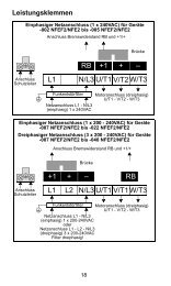
Menu<br />
PLANETARY<br />
D R I V E<br />
SYSTEMS<br />
PG / PGA<br />
SERIES<br />
STÖWER ANTRIEBSTECHNIK GMBH Enneststr. 3, 51702 Bergneustadt, Tel.: 02261 - 40970 Fax: 41309
INFORMAZIONI GENERALI<br />
GENERAL INFORMATION<br />
INFORMATIONS GENERALES<br />
ALLGEMEINE INFORMATION<br />
L’Azienda<br />
Il Prodotto<br />
Le Applicazioni<br />
Caratteristiche<br />
Tecniche<br />
Installazione<br />
Manutenzione<br />
Lubrificazione<br />
Layout<br />
Designazione Prodotto<br />
Simbologia<br />
The Company<br />
The Product<br />
The Applications<br />
Technical<br />
Information<br />
Installation<br />
Maintenance<br />
Lubrication<br />
Layout<br />
Product I<strong>de</strong>ntification<br />
Symbols<br />
SCHEDE TECNICHE RIDUTTORI<br />
PLANETARY GEARS TECHNICAL SHEETS<br />
FICHES TECHNIQUES REDUCTEURS<br />
TECHNISCHE DATENBLÄTTER GETRIEBE<br />
PG<br />
PGA<br />
100<br />
160<br />
250<br />
500<br />
700<br />
1000<br />
1600<br />
1800<br />
2500<br />
3000<br />
3500<br />
5000<br />
6500<br />
9000<br />
14000<br />
18000<br />
22000<br />
33000<br />
40000<br />
55000<br />
65000<br />
LEGENDA<br />
Dati Tecnici<br />
Technical Details<br />
Données Techniques<br />
Technische Daten<br />
42<br />
50<br />
58<br />
66<br />
74<br />
82<br />
90<br />
98<br />
106<br />
114<br />
122<br />
130<br />
138<br />
146<br />
154<br />
162<br />
170<br />
178<br />
184<br />
190<br />
194<br />
ACCESSORI ENTRATA<br />
INPUT FITTINGS<br />
ACCESSOIRES D'ENTREE<br />
ANTRIEBSBAUTEILE<br />
Freni Modulari<br />
Alberi di Entrata<br />
Entrate Dirette<br />
Predisposizioni Motori<br />
Idraulici<br />
Predisposizioni Motori<br />
Elettrici<br />
Predisposizioni<br />
Riduttori<br />
LEGEND<br />
Dimensioni<br />
Dimensions<br />
Dimensions<br />
Massen<br />
44<br />
52<br />
60<br />
68<br />
76<br />
84<br />
92<br />
100<br />
108<br />
116<br />
124<br />
132<br />
140<br />
148<br />
156<br />
164<br />
172<br />
180<br />
186<br />
192<br />
196<br />
Modular Brakes<br />
Input Shafts<br />
Direct Inputs<br />
Hydraulic Motor<br />
Couplings<br />
Electric Motor<br />
Couplings<br />
Gearbox<br />
Adaptors<br />
La Société<br />
Le Produit<br />
Les Applications<br />
Caracteristiques<br />
Techniques<br />
Installation<br />
Entretien<br />
Lubrification<br />
Schema<br />
Designation Produit<br />
Symboles<br />
LEGENDE<br />
Acessori Uscita<br />
Output Fittings<br />
Accessoires <strong>de</strong> Sortie<br />
Abtriebsbauteile<br />
48<br />
56<br />
64<br />
72<br />
80<br />
88<br />
96<br />
104<br />
112<br />
120<br />
128<br />
136<br />
144<br />
152<br />
160<br />
168<br />
176<br />
182<br />
188<br />
-<br />
-<br />
Freins Modulaires<br />
Arbres d'Entrée<br />
Entrées Directes<br />
Adaptations Moteurs<br />
Hydrauliques<br />
Adaptations Moteurs<br />
Electriques<br />
Adaptations<br />
Réducteurs<br />
Das Unternehmen<br />
Das Produkt<br />
Die Einsatzbereiche<br />
Technische<br />
Eigenschaften<br />
Einbau<br />
Wartung<br />
Schmierung<br />
Layout<br />
Produktbezeichnung<br />
Legen<strong>de</strong><br />
LEGENDE<br />
Carichi Radiali<br />
Radial Loads<br />
Charges Radiale<br />
Radiallast<br />
49<br />
57<br />
65<br />
73<br />
81<br />
89<br />
97<br />
105<br />
113<br />
121<br />
129<br />
137<br />
145<br />
153<br />
161<br />
169<br />
177<br />
183<br />
189<br />
-<br />
-<br />
Bremsmodule<br />
Antriebswellen<br />
Standardantrieb<br />
Motorflansch<br />
Hydraulikmotoren<br />
Motorflansch<br />
Elektromotoren<br />
Motorflansch<br />
<strong>Getriebe</strong><br />
Menu<br />
2<br />
2<br />
3<br />
4<br />
6<br />
20<br />
23<br />
34<br />
36<br />
38<br />
39<br />
40<br />
42<br />
50<br />
58<br />
66<br />
74<br />
82<br />
90<br />
98<br />
105<br />
114<br />
122<br />
130<br />
138<br />
146<br />
154<br />
162<br />
170<br />
178<br />
184<br />
190<br />
194<br />
199<br />
200<br />
202<br />
206<br />
213<br />
217<br />
218<br />
INDICE - INDEX - INDEX - INHALT
CARATTERISTICHE<br />
TECNICHE<br />
La conoscenza e l’esatta interpretazione<br />
<strong>de</strong>i dati riportati sul<br />
presente catalogo sono condizione<br />
indispensabile per la scelta<br />
e l’impiego corretto <strong>de</strong>i prodotti<br />
presentati.<br />
È importante quindi <strong>de</strong>finire alcuni<br />
parametri caratteristici:<br />
RAPPORTO DI TRASMISSIO-<br />
NE i<br />
È il valore effettivo <strong>de</strong>l rapporto<br />
tra la velocità di entrata n1 ela<br />
velocità di uscita n2.<br />
Viene indicato per ogni tipo di riduttore<br />
nella relativa scheda<br />
tecnica.<br />
VELOCITÀ MASSIMA IN<br />
ENTRATA<br />
n1max [min- 1 ]<br />
Rappresenta il valore massimo<br />
accettabile per ogni gran<strong>de</strong>zza<br />
di riduttore, in condizioni di funzionamento<br />
intermittente. Per<br />
applicazioni in servizio continuo<br />
o per velocità superiori a quelle<br />
indicate, il Servizio Tecnico<br />
Commerciale SOM è a disposizione<br />
per ulteriori chiarimenti.<br />
I valori <strong>de</strong>lla velocità massima<br />
in entrata per ogni tipo di riduttore<br />
sono illustrati nelle singole<br />
sche<strong>de</strong> tecniche.<br />
COPPIA CONTINUA<br />
Mc [kNm]<br />
È quella coppia per cui il valore<br />
<strong>de</strong>lle sollecitazioni sugli ingranaggi<br />
è pari al valore limite secondo<br />
le norme internazionali<br />
ISO 6336.<br />
Questo valore convenzionale<br />
corrispon<strong>de</strong> ad una durata di<br />
vita teorica illimitata <strong>de</strong>gli ingranaggi,<br />
tenendo conto sia <strong>de</strong>lla<br />
sollecitazione a flessione che<br />
<strong>de</strong>lla resistenza superficiale <strong>de</strong>l<br />
<strong>de</strong>nte (pressione di Hertz).<br />
GENERAL TECHNICAL IN-<br />
FORMATION<br />
The knowledge and correct interpretation<br />
of the information<br />
given in this catalogue are necessary<br />
starting-points for the<br />
best selection and use of the<br />
products.<br />
It is important to <strong>de</strong>termine<br />
some distinctive parameters<br />
such as:<br />
REDUCTION RATIO i<br />
This is the ratio of input speed<br />
n1 to output speed n2.<br />
The value for each planetary<br />
gear is shown in the relative<br />
technical card.<br />
MAXIMUM INPUT SPEED<br />
n1max [min -1 ]<br />
This is the maximum speed allowed<br />
for each size of planetary<br />
gear un<strong>de</strong>r conditions of intermittent<br />
work. In continuous duty<br />
or speeds greater than the ones<br />
indicated, please contact the<br />
SOM Technical-Commercial<br />
Service Department.<br />
Maximum input values for each<br />
type of planetary gear are <strong>de</strong>picted<br />
in the single technical<br />
card.<br />
CONTINUOUS TORQUE<br />
Mc [kNm]<br />
This is the torque value related<br />
to the maximum value of the<br />
stress on the gears according to<br />
the international standards ISO<br />
6336.<br />
This conventional torque value<br />
corresponds to the unlimited<br />
theoretic life of the gears, taking<br />
into consi<strong>de</strong>ration the bending<br />
stress as well as the surface<br />
strength of the tooth (Hertz<br />
pressure).<br />
CARACTERISTIQUES<br />
TECHNIQUES<br />
La connaissance et la bonne interprétation<br />
<strong>de</strong>s données contenues<br />
dans ce catalogue sont les<br />
conditions indispensables qui<br />
permettent <strong>de</strong> choisir et d’employer<br />
correctement les produits présentés.<br />
Il est donc important <strong>de</strong> définir<br />
certains parametres caracteristiques:<br />
LE RAPPORT DE TRANSMIS-<br />
SION i<br />
C’est le rapport effectif entre la<br />
vitesse d’entrée n1 et la vitesse<br />
<strong>de</strong> sortie n2.<br />
Il est indiqué sur la fiche technique<br />
<strong>de</strong> chaque type <strong>de</strong> réducteurs.<br />
LA VITESSE MAXIMALE<br />
D’ENTREE<br />
n1max [min -1 ]<br />
C’est la vitesse maximale admise<br />
pour chaque famille <strong>de</strong> réducteurs,<br />
dans <strong>de</strong>s conditions<br />
<strong>de</strong> fonctionnement intermittent.<br />
Pour <strong>de</strong>s applications en service<br />
continu ou bien pour <strong>de</strong>s<br />
vitesses supérieures à celles<br />
qui sont indiquées, le Service<br />
Technico-Commercial est à<br />
votre disposition pour <strong>de</strong>s explications<br />
supplémentaires.<br />
La vitesse maximale d’entrée<br />
est indiquée sur la fiche technique<br />
<strong>de</strong> chaque type <strong>de</strong> réducteur.<br />
TECHNISCHE<br />
EIGENSCHAFTEN<br />
Die Kenntnis <strong>de</strong>r Anfor<strong>de</strong>rung,<br />
sowie die korrekte Umsetzung<br />
<strong>de</strong>r im Katalog gelieferten Daten<br />
sind Voraussetzung für die<br />
gezielte Auswahl und somit <strong>de</strong>n<br />
erfolgreichen Einsatz <strong>de</strong>s entsprechen<strong>de</strong>n<br />
Produktes.<br />
Es ist <strong>de</strong>shalb wichtig, die folgen<strong>de</strong>n<br />
Bestimmungsfaktoren<br />
festzulegen:<br />
ÜBERSETZUNG i<br />
Es han<strong>de</strong>lt sich um <strong>de</strong>n Quotienten<br />
aus Antriebsdrehzahl n1<br />
und Abtriebsdrehzahl n2.<br />
Sie wird für je<strong>de</strong>s <strong>Getriebe</strong>mo<strong>de</strong>ll<br />
im jeweiligen technischen<br />
Datenblatt angegeben.<br />
MAXIMAL ZULÄSSIGE AN-<br />
TRIEBSDREHZAHL<br />
n1max [min -1 ]<br />
Im Dauerbetrieb mit Antriebsdrehzahlen,<br />
die die angegebenen<br />
Werte überschreiten, halten<br />
Sie bitte Rücksprache mit <strong>de</strong>m<br />
Kun<strong>de</strong>nservice (Sales) von<br />
SOM.<br />
Die Werte <strong>de</strong>r zulässigen Eingangsdrehzahl<br />
sind für je<strong>de</strong>s<br />
<strong>Getriebe</strong>mo<strong>de</strong>ll im technischen<br />
Datenblatt angegeben.<br />
RENDIMENTO<br />
EFFICIENCY<br />
LE RENDEMENT<br />
WIRKUNGSRAD<br />
Nella trasmissione epicicloidale,<br />
il rendimento è generalmente<br />
elevato, mediamente 0,97- 0,98<br />
per ogni stadio di riduzione. Questo<br />
dato indicativo si riduce nel<br />
caso di funzionamenti a velocità<br />
elevate o nel caso di riduttori in<br />
versione angolare.<br />
The efficiency is usually high in<br />
planetary transmission; i.e., the<br />
average value ranges between<br />
0.97 and 0.98 for each reduction<br />
stage. This approximate<br />
value <strong>de</strong>creases un<strong>de</strong>r conditions<br />
of high speed or in applications<br />
with bevel gears.<br />
Il est généralement élevé dans<br />
la transmission planétaire:<br />
0,97-0,98 en moyenne pour<br />
chaque étage <strong>de</strong> réduction.<br />
Cette donnée indicative peut<br />
être inférieure dans le cas <strong>de</strong><br />
fonctionnements à <strong>de</strong>s vitesses<br />
très élevées et dans le cas <strong>de</strong><br />
réducteurs en version angulaire.<br />
Der Wirkungsgrad <strong>de</strong>s Planetengetriebes<br />
liegt pro Planetenstufe<br />
bei 98%; d.h. bei einem<br />
dreistufigem <strong>Getriebe</strong> n gesamt<br />
= 0,98 x 0,98 x 0,98 = 94%.<br />
6<br />
CARATTERISTICHE TECNICHE<br />
TECHNICAL INFORMATION<br />
CARACTERISTIQUES TECHNIQUES<br />
TECHNISCHE EIGENSCHAFTEN<br />
LE COUPLE CONTINU<br />
Mc [kNm]<br />
C’est le couple dont la valeur<br />
<strong>de</strong>s contraintes sur les engrenages<br />
est égale à la valeur limite<br />
selon les normes internationales<br />
ISO 6336.<br />
Cette valeur conventionnelle<br />
correspond à une durée théorique<br />
illimitée <strong>de</strong>s engrenages,<br />
tenant compte aussi bien <strong>de</strong> la<br />
contrainte <strong>de</strong> flexion que <strong>de</strong> la<br />
résistance <strong>de</strong> la surface <strong>de</strong> la<br />
<strong>de</strong>nt (pression <strong>de</strong> Hertz).<br />
STÖWER ANTRIEBSTECHNIK GMBH<br />
STÖWER ANTRIEBSTECHNIK GMBH<br />
Menu<br />
DAUERDREHMOMENT<br />
Mc [kNm]<br />
Dieser allgemein festgelegte<br />
Wert entspricht einer theoretisch<br />
unbegrenzten Lebensdauer<br />
<strong>de</strong>r Zahnrä<strong>de</strong>r, wobei sowohl<br />
die Biegespannung als auch die<br />
zulässige Hertzsche Pressung<br />
auf die Zahnflankenoberfläche<br />
berücksichtigt wer<strong>de</strong>n.<br />
Es han<strong>de</strong>lt sich um das Limit<br />
<strong>de</strong>r Beanspruchung an die Verzahnung<br />
gemaess <strong>de</strong>r Norm<br />
ISO 6336
Ai fini <strong>de</strong>lla scelta <strong>de</strong>l riduttore<br />
questo valore va posto in riferimento<br />
alla COSTANTE DI<br />
DURATA nxh espressa nel Diagramma<br />
1 dove:<br />
n = velocità in uscita (min -1 )<br />
h = durata di funzionamento (ore).<br />
Per semplicità di consultazione,<br />
nella scheda tecnica di prodotto<br />
sono riportati i valori di Mc corrispon<strong>de</strong>nti<br />
ad un valore n2xh<br />
prefissato.<br />
COPPIA MASSIMA<br />
Mmax [kNm]<br />
È il valore massimo di coppia<br />
che il riduttore può trasmettere<br />
per breve tempo senza che si<br />
verifichino danneggiamenti ai<br />
suoi componenti interni ed alla<br />
sua struttura. Tale valore <strong>de</strong>ve<br />
essere consi<strong>de</strong>rato come una<br />
coppia massima dovuta a picchi<br />
o spunti di avviamento e mai<br />
come coppia di lavoro; il valore<br />
Mmax <strong>de</strong>ve inoltre essere opportunamente<br />
valutato in quegli<br />
azionamenti che comportano un<br />
elevato numero di avviamenti o<br />
inversioni.<br />
Il valore Mmax è indicato nelle<br />
sche<strong>de</strong> tecniche di prodotto.<br />
TEMPERATURA DI FUNZIO-<br />
NAMENTO<br />
Le temperature <strong>de</strong>ll’olio a cui i<br />
riduttori possono funzionare<br />
sono quelle comprese tra -20°C<br />
e + 90°C. Temperature al di fuori<br />
di questa fascia possono essere<br />
accettate se si prevedono<br />
particolari accorgimenti relativi<br />
ai tipi di lubrificante e di guarnizioni<br />
utilizzati. Tali accorgimenti<br />
possono essere <strong>de</strong>cisi caso per<br />
caso, d’accordo con il Servizio<br />
Tecnico-Commerciale SOM.<br />
POTENZA TERMICA<br />
Pt [kW]<br />
È la potenza massima trasmissibile<br />
dal riduttore in funzionamento<br />
continuo con lubrificazione<br />
normale a sbattimento, senza<br />
che l’olio superi la temperatura<br />
di 90°C. I valori di Pt<br />
riportati nelle singole sche<strong>de</strong><br />
tecniche di prodotto sono valori<br />
massimi espressi alle seguenti<br />
condizioni di impiego:<br />
• servizio continuo<br />
• velocità n 1 = 1500 min -1<br />
In regard to the selection of the<br />
planetary gear, this value represents<br />
the CONSTANT OF<br />
LIFETIME nxh as shown in<br />
Curve 1 where:<br />
n = output speed (min -1 )<br />
h = working time (hours)<br />
In or<strong>de</strong>r to simplify yuor consultation,<br />
the single product technical<br />
cards show the Mc values<br />
referring to a fixed n2xh value.<br />
MAXIMUM TORQUE<br />
Mmax [kNm]<br />
CARATTERISTICHE TECNICHE<br />
TECHNICAL INFORMATION<br />
CARACTERISTIQUES TECHNIQUES<br />
TECHNISCHE EIGENSCHAFTEN<br />
This is the maximum output torque<br />
that the planetary unit can<br />
transmit in a short time without<br />
causing damage to the internal<br />
components and structure. This<br />
value must be consi<strong>de</strong>red as<br />
the maximum output torque due<br />
to working or starting peaks<br />
and never as the continuous<br />
working torque. It also must be<br />
carefully evaluated in those applications<br />
with a high number of<br />
starts or setting ups.<br />
The Mmax value is shown in the<br />
single product technical cards.<br />
WORKING TEMPERATURE<br />
The working oil temperature of<br />
the planetary gears should range<br />
between -20°C and + 90°C.<br />
Temperatures falling outsi<strong>de</strong><br />
this range could be accepted<br />
only if special lubricants and<br />
gaskets are used. For further<br />
information, please contact the<br />
SOM Technical-Commercial<br />
Service Department.<br />
THERMAL POWER<br />
Pt [kW]<br />
The thermal power is the maximum<br />
power the planetary unit<br />
can transmit in continuous duty<br />
with normal turbolence lubrication<br />
and without exceeding an<br />
oil temperature of 90°C. The Pt<br />
values shown in the single product<br />
technical card indicate the<br />
maximum values at the following<br />
duty conditions:<br />
• continuous duty<br />
• speed n 1 = 1500 min -1<br />
Dans le choix du réducteur, cette<br />
valeur représente la<br />
CONSTANTE DE DUREE n x h<br />
indiquée dans le Diagramme 1.<br />
n = vitesse <strong>de</strong> sortie (min -1 .)<br />
h = durée <strong>de</strong> fonctionnement<br />
(heures)<br />
Pour simplifier la consultation,<br />
les fiches techniques <strong>de</strong>s produits<br />
montrent les valeurs <strong>de</strong><br />
Mc qui correspon<strong>de</strong>nt à une valeur<br />
n2xh prédéterminée.<br />
LE COUPLE MAXIMAL<br />
Mmax [kNm]<br />
C’est le couple maximal que le<br />
réducteur peut transmettre pendant<br />
une durée brève, sans provoquer<br />
<strong>de</strong> dommages à ses<br />
composants internes et à sa<br />
structure. Cette valeur doit être<br />
considérée comme étant le<br />
couple maximum enregistré lors<br />
<strong>de</strong> pointes ou <strong>de</strong> mises en<br />
marche mais jamais comme un<br />
couple continu <strong>de</strong> fonctionnement.<br />
Ce couple doit être particulièrement<br />
bien calculé lorsqu’il<br />
s’agit <strong>de</strong> transmissions comportant<br />
un nombre <strong>de</strong> mises en<br />
marche ou <strong>de</strong> démarrages élevé.<br />
La valeur <strong>de</strong> Mmax est indiquée<br />
dans chaque fiche technique <strong>de</strong><br />
produit.<br />
LA TEMPERATURE DE FON-<br />
CTIONNEMENT<br />
La température <strong>de</strong> l’huile à laquelle<br />
les réducteurs peuvent<br />
fonctionner est comprise entre<br />
-20°C et + 90°C. Des températures<br />
hors <strong>de</strong> cette fourchette<br />
sont acceptables à condition <strong>de</strong><br />
prendre <strong>de</strong>s précautions<br />
concernant le type <strong>de</strong> lubrifiant<br />
et les joints utilisés. Ces précautions<br />
sont à déterminer selon les<br />
cas, en accord avec le Service<br />
Technico-Commercial SOM.<br />
LA PUISSANCE THERMIQUE<br />
Pt [kW]<br />
C’est la puissance maximale<br />
transmissible par le réducteur<br />
en service continu avec lubrification<br />
normale par barbotage,<br />
sans que l’huile dépasse la température<br />
<strong>de</strong> 90°C.<br />
Les valeurs <strong>de</strong> Pt indiquées<br />
dans chaque fiche technique<br />
sont <strong>de</strong>s valeurs maximales relevées<br />
dans les conditions<br />
d’emploi suivantes:<br />
• service continu<br />
• vitesse n 1 = 1500 min -1<br />
STÖWER ANTRIEBSTECHNIK GMBH<br />
Menu<br />
Um eine korrekte Auswahl <strong>de</strong>s<br />
<strong>Getriebe</strong>s zu treffen, muß dieser<br />
Wert in Bezug zur LEBENS-<br />
DAUER- KONSTANTE nxh gesetzt<br />
wer<strong>de</strong>n (Diagramm 1).<br />
n = Drehzahl an <strong>de</strong>r Ausgangswelle<br />
(min -1 )<br />
h = Betriebsdauer (Stun<strong>de</strong>n)<br />
MAXIMALES DREHMOMENT<br />
Mmax [kNm]<br />
Es han<strong>de</strong>lt sich um <strong>de</strong>n maximal<br />
zulässigen Wert <strong>de</strong>s Drehmoments,<br />
<strong>de</strong>n das <strong>Getriebe</strong><br />
kurzzeitig übertragen kann,<br />
ohne daß Schä<strong>de</strong>n auftreten.<br />
Dieser Wert ist als maximales<br />
Drehmoment bei kurzzeitigen<br />
Spitzenbelastungen zu betrachten<br />
und niemals als Drehmoment<br />
bei Dauerbetrieb; er muß<br />
außer<strong>de</strong>m jeweils entsprechend<br />
<strong>de</strong>m Lastkollektiv gewertet<br />
wer<strong>de</strong>n.<br />
Der Wert Mmax wird in <strong>de</strong>n technischen<br />
Datenblaettern <strong>de</strong>s entsprechen<strong>de</strong>n<br />
<strong>Getriebe</strong>typs ausgewiesen.<br />
BETRIEBSTEMPERATUR<br />
Die <strong>Getriebe</strong> können bei einer<br />
Umgebungstemperatur zwischen<br />
-20°C und + 90°C betrieben<br />
wer<strong>de</strong>n. Ein Betrieb bei<br />
Temperaturen außerhalb dieses<br />
Bereiches ist möglich, vorausgesetzt<br />
daß beson<strong>de</strong>re Maßnahmen<br />
in Bezug auf verwen<strong>de</strong>te<br />
Schmierstoffe und<br />
Dichtungen beachtet wer<strong>de</strong>n.<br />
Diese Maßnahmen können im<br />
Einzelfall in Abstimmung mit<br />
<strong>de</strong>m Kun<strong>de</strong>nservice (Sales) von<br />
SOM entschie<strong>de</strong>n wer<strong>de</strong>n.<br />
THERMISCHE LEISTUNG<br />
Pt [kW]<br />
Es han<strong>de</strong>lt sich um die maximale<br />
Leistung, die das <strong>Getriebe</strong><br />
bei Dauerbetrieb und normaler<br />
Schmierweise übertragen kann,<br />
ohne daß die Öltemperatur von<br />
90°C überschritten wird.<br />
Die in <strong>de</strong>n jeweiligen technischen<br />
Datenblättern aufgeführten<br />
Pt- Werten sind Maximalwerte<br />
unter <strong>de</strong>n folgen<strong>de</strong>n Betriebsbedingungen:<br />
• Dauerbetrieb ohne Unterbrechungen<br />
• Drehzahl n 1 = 1500 min -1<br />
7
• olio ISO VG 150<br />
• posizione di montaggio orizzontale<br />
• temperatura ambiente 20°C.<br />
Qualora la potenza richiesta ecceda<br />
i valori indicati nella scheda<br />
tecnica <strong>de</strong>l riduttore sarà necessario<br />
preve<strong>de</strong>re un sistema<br />
di raffreddamento <strong>de</strong>l lubrificante.<br />
Per i riduttori con piedi (dalla<br />
gran<strong>de</strong>zza PG 100 alla gran<strong>de</strong>zza<br />
PG 1600) il valore di Pt<br />
può essere incrementato <strong>de</strong>l<br />
15%.<br />
Nel caso le caratteristiche di impiego<br />
siano diverse, si può applicare<br />
ai valori di Pt un fattore<br />
correttivo fk, come indica la Tabella<br />
1, di seguito riportata:<br />
8<br />
Tempo % di<br />
funzionamento<br />
Work time %<br />
Temps % <strong>de</strong><br />
fonctionnement<br />
Betriebszeit in %<br />
• oil ISO VG 150<br />
• horizontal mounting position<br />
• room temperature 20°C.<br />
If the required power exceeds<br />
the values indicated in the planetary<br />
gear technical card, a lubricant<br />
cooling system is<br />
nee<strong>de</strong>d.<br />
For foot mounted reduction<br />
units (from PG 100 serie to PG<br />
1600 serie) the Pt value can be<br />
increased by 15%.<br />
If the duty characteristics differ,<br />
you can apply a corrective factor<br />
fk to the Pt values as indicated<br />
in the following Table 1:<br />
• huile ISO VG 150<br />
• position <strong>de</strong> montage horizontale<br />
• température ambiante 20°C.<br />
Si la puissance requise dépasse<br />
les valeurs indiquées sur<br />
la fiche technique du réducteur,<br />
il est nécessaire <strong>de</strong> prévoir<br />
l’installation d’un système <strong>de</strong><br />
refroidissement du lubrifiant.<br />
En ce qui concerne les réducteurs<br />
à pattes, (<strong>de</strong> la gran<strong>de</strong>ur<br />
PG 100 à la gran<strong>de</strong>ur PG 1600)<br />
la valeur Pt peut être augmentée<br />
<strong>de</strong> 15%.<br />
Dans le cas où les caractéristiques<br />
d’emploi seraient différentes,<br />
on peut appliquer un facteur<br />
correctif fk (voir Tableau 1<br />
ci-<strong>de</strong>ssous):<br />
Fattore di a<strong>de</strong>guamento <strong>de</strong>lla capacità termica fk / Thermal power adjustment factor fk<br />
Facteur d’adaptation <strong>de</strong> la capacite thermique fk / Anpassungsfaktor Wärmekapazität fk<br />
• Öl ISO VG 150<br />
• waagerechte Einbaulage<br />
• Umgebungstemperatur+20°C<br />
Sollte die gefor<strong>de</strong>rte Leistung<br />
die im technischen Datenblatt<br />
<strong>de</strong>s <strong>Getriebe</strong>s aufgeführten<br />
Werte übersteigen, wird ein<br />
Schmiermittel-Kühlsystem erfor<strong>de</strong>rlich.<br />
Der Pt- Wert <strong>de</strong>r <strong>Getriebe</strong> in<br />
Fussaussfuehrung kann um<br />
15% erhöht wer<strong>de</strong>n.<br />
Weichen die Einsatzbedingungen<br />
von <strong>de</strong>n Normbedingungen<br />
ab, können die Pt- Werte durch<br />
<strong>de</strong>n Korrekturfaktor fk korrigiert<br />
wer<strong>de</strong>n (vgl. nachstehend aufgeführte<br />
Tabelle 1):<br />
Temperatura ambiente °C / Room temperature °C / T° Ambiante °C / Raumtemperatur In C°<br />
10° 20° 30° 40° 50°<br />
100 1.1 1.0 0.8 0.7 0.6<br />
80 1.2 1.1 1.0 0.8 0.7<br />
60 1.4 1.2 1.1 1.0 0.8<br />
40 1.6 1.4 1.2 1.1 1.0<br />
20 1.8 1.6 1.4 1.2 1.1<br />
Tabella 1 / Table 1 / Tableau 1 / Tabelle 1<br />
N.B. Si noti che la Pt è riferita<br />
alla potenza effettivamente trasmessa<br />
dal riduttore, da non<br />
confon<strong>de</strong>re quindi con la potenza<br />
<strong>de</strong>l motore su di esso installato,<br />
che per vari motivi potrebbe<br />
essere superiore.<br />
Per ulteriori <strong>de</strong>ttagli si prega di<br />
contattare il Servizio Tecnico-<br />
Commerciale SOM.<br />
FATTORE DI SERVIZIO<br />
fs<br />
È un coefficiente di moltiplicazione<br />
che viene inserito nella<br />
formula per la scelta <strong>de</strong>l riduttore.<br />
Serve per tener conto <strong>de</strong>lle condizioni<br />
di carico <strong>de</strong>ll’applicazione,<br />
ed è <strong>de</strong>finito dalla Tabella 2<br />
CARATTERISTICHE TECNICHE<br />
TECHNICAL INFORMATION<br />
CARACTERISTIQUES TECHNIQUES<br />
TECHNISCHE EIGENSCHAFTEN<br />
NOTE. Please note that the Pt<br />
refers to the power actually<br />
transmitted by the planetary<br />
gear unit. Do not mistake it with<br />
the power of the motor<br />
mounted on it which for various<br />
reasons could be greater.<br />
For further <strong>de</strong>tails please contact<br />
the SOM Technical-Commercial<br />
Service Department.<br />
Pt1 =Ptxfk<br />
SERVICE FACTOR<br />
fs<br />
Service factor fs is a multiplication<br />
coefficient introduced into<br />
the formula for the selection of<br />
the planetary gear.<br />
In that formula it takes into account<br />
the application load conditions.<br />
It is <strong>de</strong>fined in Table 2.<br />
N.B. Pt se réfère à la puissance<br />
effectivement transmise par le<br />
réducteur; il ne faut donc pas la<br />
confondre avec la puissance du<br />
moteur sur lequel le réducteur<br />
est installé, puissance qui, pour<br />
différentes raisons, peut être<br />
supérieure.<br />
Pour <strong>de</strong> plus amples détails,<br />
s’adresser au Service Technico-Commercial<br />
SOM.<br />
FACTEUR DE SERVICE<br />
fs<br />
C’est un facteur <strong>de</strong> multiplication<br />
qui est introduit dans la formule<br />
servant à choisir le réducteur.<br />
Il permet <strong>de</strong> tenir compte <strong>de</strong>s conditions<br />
<strong>de</strong> charge <strong>de</strong> l’application<br />
et est défini dans le Tableau 2.<br />
STÖWER ANTRIEBSTECHNIK GMBH<br />
Menu<br />
ANMERKUNG: Es wird darauf<br />
hingewiesen, daß sich <strong>de</strong>r Pt-<br />
Wert auf die tatsächlich vom<br />
<strong>Getriebe</strong> übertragene Leistung<br />
bezieht; sie darf nicht mit <strong>de</strong>r<br />
Leistung <strong>de</strong>s eingebauten Motors<br />
verwechselt wer<strong>de</strong>n, die<br />
höher sein könnte.<br />
Für weitere Rückfragen wen<strong>de</strong>n<br />
Sie sich bitte an <strong>de</strong>n Kun<strong>de</strong>nservice<br />
(Sales) von SOM.<br />
BETRIEBSFAKTOR<br />
fs<br />
Es han<strong>de</strong>lt sich um einen Multiplikationskoeffizienten,<br />
<strong>de</strong>r in<br />
die Formel eingesetzt wird.<br />
Damit soll <strong>de</strong>n nach Einsatzform<br />
unterschiedlichen Belastungen<br />
Rechnung getragen<br />
wer<strong>de</strong>n; er wird in Tabelle 2 aufgeführt.
CARICHI SULL’ALBERO DI<br />
USCITA E ENTRATA<br />
Fr;Fa[N]<br />
Fr =carico radiale<br />
Fa =carico assiale<br />
I valori <strong>de</strong>i carichi applicabili sugli<br />
alberi di uscita si ricavano<br />
dai diagrammi riportati in corrispon<strong>de</strong>nza<br />
di ogni gran<strong>de</strong>zza di<br />
riduttore, mentre quelli relativi<br />
agli alberi di entrata si trovano<br />
a pag. 202<br />
I carichi radiali ed assiali massimi<br />
non possono agire contemporaneamente.<br />
L’entità <strong>de</strong>i carichi ammessi Fr ,<br />
Fa è riferita ad una durata <strong>de</strong>i<br />
cuscinetti secondo ISO 281,<br />
corrispon<strong>de</strong>nte a:<br />
nxh=10 5 per alberi di uscita<br />
nxh=5x10 6 per alberi in entrata<br />
I riduttori in versione F vengono<br />
normalmente utilizzati per trasmettere<br />
coppia senza carichi<br />
radiali, pertanto non vengono<br />
indicate le capacità di Fr ed Fa<br />
massime.<br />
Per informazioni ulteriori contattare<br />
il Servizio Tecnico-Commerciale<br />
SOM.<br />
Nell’ambito <strong>de</strong>l continuo sviluppo<br />
e miglioramento <strong>de</strong>l<br />
prodotto, la SOM si riserva la<br />
facoltà di apportare le modifiche<br />
sia tecniche sia dimensionali<br />
che saranno ritenute<br />
opportune, senza darne<br />
espresso preavviso.<br />
OUTPUT AND INPUT SHAFT<br />
LOADS<br />
Fr;Fa[N]<br />
Fr = radial load<br />
Fa = axial load<br />
The load values that output<br />
shafts can bear are indicated<br />
on the load curves shown on<br />
each gear box size; the load<br />
values relevant to input shafts<br />
are shown at page 202.<br />
Radial and axial loads are the<br />
maximum values permitted but<br />
must not occur simultaneously.<br />
The values of permitted loads<br />
Fr, Fa are referred to a bearing<br />
duration according to ISO 281<br />
standard and corresponding to:<br />
nxh=10 5 for output shafts<br />
nxh=5x10 6 for input shafts<br />
F gear units are usually applied<br />
in the transmission of a torque<br />
without radial loads. In this<br />
case, maximum values Fr and<br />
Fa are not shown.<br />
For further information, please<br />
contact the SOM Technical-<br />
Commercial Service Department.<br />
SOM S.p.A. is continuously<br />
improving its product and<br />
will un<strong>de</strong>rtake the necessary<br />
technical and dimensional<br />
changes without needing a<br />
previous notice to the market.<br />
PRIME MOVER<br />
e) type and characteristics<br />
of the prime mover<br />
f) power and/or torque<br />
supplied<br />
g) working speed<br />
CHARGES SUR L’ARBRE DE<br />
SORTIE ET D'ENTREE<br />
Fr;Fa[N]<br />
Fr = charge radiale<br />
Fa = charge axiale<br />
Les valeurs <strong>de</strong>s charges applicables<br />
sur l’arbre <strong>de</strong> sortie sont<br />
indiquées dans les diagrammes<br />
correspondants à chaque famille<br />
<strong>de</strong> réducteur; les valeurs <strong>de</strong>s<br />
charges qui se referrent aux arbres<br />
d'entrée se trouvent à la<br />
page 202.<br />
Les charges radiales et axiales<br />
maximales ne sont pas cumulables.<br />
La valeur <strong>de</strong>s charges admissibles<br />
Fr , Fa se réfère à une durée<br />
<strong>de</strong>s coussinets ISO 281,<br />
correspondant à:<br />
nxh=10 5 pour arbres <strong>de</strong> sortie<br />
nxh=5x10 6 pour arbres d'entrée<br />
Les réducteurs version F sont<br />
normalement utilisés pour transmettre<br />
un couple sans charges<br />
radiales; par conséquent,<br />
les charges maximales Fr et Fa<br />
ne sont pas indiquées.<br />
Pour <strong>de</strong> plus amples informations,<br />
s’adresser au Service<br />
Technico-Commercial SOM.<br />
SOM se réserve le droit<br />
d’apporter, sans préavis, les<br />
modifications <strong>de</strong> type technique<br />
et dimensionnel jugées<br />
nécessaires au développement<br />
et à l’amélioration constant<br />
<strong>de</strong> ses produits.<br />
MOTEUR<br />
e) type et caractéristiques du<br />
moteur<br />
f) puissance et/ou couple<br />
produits<br />
g) vitesse <strong>de</strong> fonctionnement<br />
BELASTUNG DER ABTRIEBS-<br />
WELLE UND ANTRIEBS-<br />
WELLE Fr;Fa[N]<br />
Fr = Radiallast<br />
Fa = Axiallast<br />
Die Belastbarkeit <strong>de</strong>r Abtriebswelle<br />
ergibt sich aus <strong>de</strong>n je<strong>de</strong>r<br />
<strong>Getriebe</strong>größe zugeordneten<br />
Diagrammen. Dagegen sind die<br />
Werte <strong>de</strong>r Antriebswelle auf <strong>de</strong>r<br />
S. 202 ersichtlich.<br />
Die zulässigen Maximalwerte<br />
<strong>de</strong>r Radial- und Axialbelastungen<br />
dürfen nicht gleichzeitig<br />
auftreten.<br />
Der Wert <strong>de</strong>r zulässigen Belastung<br />
durch Fr und Fa bezieht<br />
sich auf eine Betriebsdauer<br />
nach ISO 281, das entspricht:<br />
nxh=10 5 fuer Abtriebswelle<br />
nxh=5x10 6 fuer Antriebswelle<br />
Die <strong>Getriebe</strong> in Ausführung F<br />
wer<strong>de</strong>n in <strong>de</strong>r Regel für die<br />
Übertragung von Drehmomenten<br />
ohne Radialbelastung eingesetzt.<br />
Deshalb wer<strong>de</strong>n Fr<br />
und Fa nicht angegeben. Für<br />
weitere Rückfragen wen<strong>de</strong>n Sie<br />
sich bitte an <strong>de</strong>n Kun<strong>de</strong>nservice<br />
(Sales) von SOM.<br />
Im Rahmen <strong>de</strong>r ständigen<br />
Weiterentwicklung und Verbesserung<br />
<strong>de</strong>r Produkte behält<br />
sich SOM das Recht vor,<br />
erfor<strong>de</strong>rliche technische Än<strong>de</strong>rungen<br />
ohne ausdrückliche<br />
Vorankündigung durchzufuehren.<br />
SCELTA DEL RIDUTTORE PLANETARY UNIT SELECTION SELECTION DU REDUCTEUR GETRIEBEAUSWAHL<br />
In una trasmissione meccanica,<br />
il riduttore è un organo inserito<br />
tra motore ed utenza.<br />
Le sollecitazioni a cui è sottoposto<br />
durante il funzionamento<br />
sono funzione <strong>de</strong>lle curve caratteristiche<br />
<strong>de</strong>l motore come di<br />
quelle <strong>de</strong>ll’utenza (assorbimento<br />
e ciclo di lavoro).<br />
La conoscenza <strong>de</strong>lla trasmissione<br />
nella sua interezza è condizione<br />
necessaria per la corretta<br />
scelta <strong>de</strong>l riduttore.<br />
È necessario conoscere:<br />
In a mechanical transmission<br />
system, a planetary unit is a <strong>de</strong>vice<br />
positioned between the prime<br />
mover and the driven equipment.<br />
The stress it is subject to during<br />
operation is strictly related to<br />
the characteristics of the prime<br />
mover and the driven equipment<br />
(power absorption and<br />
working cycle).<br />
The knowledge of the transmission<br />
system as a whole is a necessary<br />
condition for the best<br />
planetary unit selection.<br />
It is necessary to know:<br />
Dans un système <strong>de</strong> transmission<br />
mécanique, le réducteur<br />
est un organe situé entre le moteur<br />
et la machine à entraîner.<br />
Les sollicitations auxquelles il<br />
est soumis pendant le fonctionnement<br />
dépen<strong>de</strong>nt strictement<br />
<strong>de</strong>s caractéristiques du moteur<br />
ainsi que <strong>de</strong> la machine à entraîner<br />
(absorption <strong>de</strong> puissance<br />
et cycle <strong>de</strong> travail).<br />
La connaissance <strong>de</strong> tout le<br />
système <strong>de</strong> transmission est<br />
une condition indispensable<br />
pour une sélection correcte du<br />
réducteur. Il faut connaître:<br />
In einem mechanischen System<br />
ist das <strong>Getriebe</strong> eine Einheit<br />
zwischen Motor und anzutreiben<strong>de</strong>r<br />
Maschine. Die Belastungen<br />
die auf <strong>de</strong>m <strong>Getriebe</strong><br />
während <strong>de</strong>s Betriebes wirken,<br />
sind eine Funktion sowohl <strong>de</strong>r<br />
Motor- als auch <strong>de</strong>r Maschinenkennlinie<br />
(Leistungsaufnahme<br />
und Lastkollektiv).<br />
Die Kenntnis <strong>de</strong>s gesamten Antriebsystems<br />
ist Voraussetzung<br />
für die korrekte Auswahl <strong>de</strong>s<br />
<strong>Getriebe</strong>s. Man sollte folgen<strong>de</strong><br />
Daten beruecksichtigen:<br />
UTENZA<br />
a) tipo di servizio<br />
b) velocità di rotazione<br />
c) potenza e/o coppia<br />
assortita<br />
d) ciclo di lavoro<br />
DRIVEN EQUIPEMENT<br />
a) type of operation<br />
b) rotation speed<br />
c) power and/or torque<br />
absorption<br />
d) working cycle<br />
MACHINE A ENTRAINEE<br />
a) type <strong>de</strong> service<br />
b) vitesse <strong>de</strong> rotation<br />
c) absorption <strong>de</strong> puissance<br />
et/ou couple<br />
d) cycle <strong>de</strong> travail<br />
ANZUTREIBENDE MASCHINE<br />
a) Einsatz<br />
b) Drehgeschwindigkeit<br />
c) Leistung und/o<strong>de</strong>r<br />
d) Lastkollektiv<br />
MOTORE<br />
e) tipo e caratteristiche <strong>de</strong>l<br />
motore<br />
f) potenza e/o coppia<br />
erogata<br />
g) velocità di funzionamento<br />
CARATTERISTICHE TECNICHE<br />
TECHNICAL INFORMATION<br />
CARACTERISTIQUES TECHNIQUES<br />
TECHNISCHE EIGENSCHAFTEN<br />
STÖWER ANTRIEBSTECHNIK GMBH<br />
Menu<br />
MOTOR<br />
e) Typ und Eigenschaften<br />
<strong>de</strong>s Motors<br />
f) Leistung und/o<strong>de</strong>r<br />
Drehmoment<br />
g) Drehgeschwindigkeit<br />
9
Queste informazioni permettono<br />
una prima scelta <strong>de</strong>i riduttori<br />
dopo aver <strong>de</strong>terminato:<br />
• rapporto di trasmissione i<br />
• coppia di lavoro M [kNm]<br />
• carichi sull’albero in uscita e<br />
in entrata al riduttore Fr; Fa<br />
[N]<br />
Successivamente si dovrà proce<strong>de</strong>re<br />
alle verifiche <strong>de</strong>i parametri<br />
caratteristici <strong>de</strong>i riduttori<br />
come segue:<br />
I) velocità in ingresso al<br />
riduttore ≤ n1 max<br />
II) coppia di lavoro ≤ Mc<br />
III) carichi applicati all’albero in<br />
uscita e in entrata ≤ Fr;Fa<br />
IV) potenza da trasmettere ≤ Pt<br />
(se in servizio continuo)<br />
V) temperatura ambiente<br />
Le relazioniIeVsono di<br />
immediata verifica mentre per la<br />
II, la III e la IV si proce<strong>de</strong> come<br />
segue:<br />
VERIFICA DEL RIDUTTORE<br />
IN FUNZIONE DELLA COPPIA<br />
Calcolo <strong>de</strong>lla coppia equivalente<br />
Me [kNm]<br />
Quando il carico è variabile nel<br />
tempo (Istogramma 1), si <strong>de</strong>ve<br />
<strong>de</strong>terminare il valore <strong>de</strong>lla coppia<br />
equivalente.<br />
Con il criterio <strong>de</strong>l cumulativo di<br />
carico si calcola, con la formula<br />
sotto indicata, la coppia in grado<br />
di provocare lo stesso livello<br />
di usura dopo il numero di cicli<br />
(nxh) richiesto dal progetto.<br />
10<br />
Istogramma 1<br />
Histogram 1<br />
Histogramme 1<br />
Histogramm 1<br />
M<br />
M1<br />
Me<br />
M2<br />
M3<br />
CARATTERISTICHE TECNICHE<br />
TECHNICAL INFORMATION<br />
CARACTERISTIQUES TECHNIQUES<br />
TECHNISCHE EIGENSCHAFTEN<br />
By means of this information it<br />
becomes possible to proceed to<br />
an initial planetary unit selection<br />
after <strong>de</strong>termining:<br />
• reduction ratio i<br />
• working torque M [kNm]<br />
• loads on planetary unit<br />
output and input shaft Fr; Fa<br />
[N]<br />
Subsequently, we are to verify<br />
some distinctive parameters of<br />
the planetary unit as follows:<br />
I) input rotation peed ≤n1 max<br />
II) working torque ≤ Mc<br />
III) loads on output and input<br />
shafts ≤ Fr;Fa<br />
IV) horsepower to be transmitted<br />
≤ Pt (if un<strong>de</strong>r continuous<br />
duty)<br />
V) room temperature<br />
Relations I and V can be readily<br />
verified; as for relations II, III<br />
and IV we must proceed as<br />
follows:<br />
VERIFICATION OF THE PLAN-<br />
ETARY UNIT ACCORDING TO<br />
THE TORQUE<br />
Calculation of the equivalent<br />
working torque Me [kNm]<br />
When loads are intermittent<br />
(see Histogram 1), it is necessary<br />
to <strong>de</strong>termine the value of<br />
the equivalent working torque.<br />
We adopt the principle of cumulative<br />
load and <strong>de</strong>termine the<br />
torque value which produces<br />
the same fatigue after the number<br />
of cycles (nxh) required by<br />
the project, by means of the following<br />
formula:<br />
6<br />
Ces informations nous permettent<br />
une première selection du<br />
réducteur après avoir déterminé:<br />
• le rapport <strong>de</strong> transmission i<br />
• le couple <strong>de</strong> travail M [kNm]<br />
• les charges sur l’arbre <strong>de</strong><br />
sortie et d'entrée du réducteur<br />
Fr; Fa [N]<br />
Par la suite il faudra vérifier certains<br />
paramètres distinctifs <strong>de</strong>s<br />
réducteurs, notamment:<br />
I) Vitesse d’entrée ≤ n1 max<br />
II) Couple <strong>de</strong> travail ≤ Mc<br />
III) Charges sur l’arbre <strong>de</strong> sortie<br />
et d'entrée ≤ Fr;Fa<br />
IV) Puissance à transmettre<br />
≤ Pt (si le service est<br />
continu)<br />
V) température ambiante<br />
Les relations I et V peuvent être<br />
immédiatement vérifiées, alors<br />
que pour les relations II, III et IV<br />
on doit procé<strong>de</strong>r comme suit:<br />
VERIFICATION DU REDUC-<br />
TEUR PAR RAPPORT AU<br />
COUPLE<br />
Calcul du couple equivalent<br />
Me [kNm]<br />
Lorsque les charges sont intermittentes<br />
(voir Histogramme 1),<br />
il faut déterminer la valeur du<br />
couple équivalent.<br />
On adopte le principe du cumul<br />
<strong>de</strong>s charges et, au moyen <strong>de</strong> la<br />
formule ci-<strong>de</strong>ssous, on trouve<br />
la valeur du couple qui détermine<br />
le même niveau d’usure<br />
pour le nombre <strong>de</strong> cycles (nxh)<br />
requis par le projet.<br />
( n x h ) ( n x h ) ( n x h )<br />
( n x h) ( n x h) ( n x h)<br />
1 1<br />
2 2 3 3<br />
6 6 6<br />
3<br />
Me = M1 + M2 + M<br />
nxh 1 1 nxh 2 2 nxh 3 3<br />
0.1 0.2 0.3 0.4 0.5 0.6 0.7 0.8 0.9 1<br />
nxh<br />
STÖWER ANTRIEBSTECHNIK GMBH<br />
Menu<br />
Diese Daten ermöglichen eine<br />
erste Auswahl <strong>de</strong>s <strong>Getriebe</strong>s<br />
und zwar nach <strong>de</strong>r Festlegung<br />
von:<br />
• Übersetzung i<br />
• Arbeitsdrehmoment M [kNm]<br />
• Belastung an <strong>de</strong>r Abtriebs- und<br />
Antriebswelle Fr, Fa [N]<br />
Danach sind folgen<strong>de</strong> Parameter<br />
zu überprüfen:<br />
I) <strong>Getriebe</strong>drehzahl ≤ n1 max<br />
II) Betriebsdrehmoment ≤ Mc<br />
III) Belastungen auf <strong>de</strong>r<br />
Abtriebswelle und<br />
Antriebswelle ≤ Fr;Fa<br />
IV) Wärmeleistung ≤ Pt<br />
(Dauerbetrieb)<br />
V) Umgebungstemperatur<br />
Die Parameter I und V kann<br />
man ohne weiteres prüfen. Was<br />
II, III und IV betrifft, ist wie folgt<br />
vorzugehen:<br />
ÜBERPRÜFUNG DES GE-<br />
TRIEBES AUFGRUND DES<br />
DREHMOMENTS<br />
Berechnung <strong>de</strong>s equivalenten<br />
Drehmoments Me [kNm]<br />
Wenn die Belastung während<br />
<strong>de</strong>r Einsatzdauer variiert (siehe<br />
z.B. Diagramm 1), soll man einen<br />
Durchschnittswert ermitteln.<br />
Nach <strong>de</strong>m Lastkollektiv wird<br />
das Drehmoment mit <strong>de</strong>r unten<br />
angegebenen Formel berechnet.
Fattore di durata fh<br />
Nelle applicazioni industriali o<br />
di norma quando il numero di<br />
cicli di lavoro previsto nxh supera<br />
2x10 4 , si ren<strong>de</strong> necessario<br />
introdurre un fattore di durata fh<br />
(con l’ausilio <strong>de</strong>l Diagramma 1)<br />
per a<strong>de</strong>guare il valore <strong>de</strong>lla<br />
coppia di catalogo Mc ad un valore<br />
che permetta di raggiungere<br />
il numero di cicli (nxh) <strong>de</strong>signato<br />
a progetto.<br />
Diagramma 1<br />
Dyagram 1<br />
Diagramme 1<br />
Diagramm 1<br />
fh<br />
3<br />
2.5<br />
2<br />
1.5<br />
1<br />
0.8<br />
0.6<br />
0.5<br />
0.4<br />
0.3<br />
0.2<br />
0.1<br />
10 3<br />
Determinazione <strong>de</strong>l fattore dl<br />
servizio fs<br />
L’effetto <strong>de</strong>gli urti <strong>de</strong>rivanti da<br />
irregolarità <strong>de</strong>l moto, dai sovraccarichi<br />
nei transitori di velocità<br />
(avviamenti ed arresti), viene<br />
conteggiato introducendo un<br />
fattore di servizio fs.<br />
La Tabella 2 indica i fattori fs in<br />
funzione <strong>de</strong>l tipo di applicazione.<br />
CARATTERISTICHE TECNICHE<br />
TECHNICAL INFORMATION<br />
CARACTERISTIQUES TECHNIQUES<br />
TECHNISCHE EIGENSCHAFTEN<br />
Duration factor fh<br />
Le facteur <strong>de</strong> duree fh<br />
On industrial installations and<br />
whenever the number of working<br />
cycles nxh exceeds 2x10 4 ,<br />
it becomes necessary to consi<strong>de</strong>r<br />
a duration factor fh (see<br />
Curve 1) in or<strong>de</strong>r to adapt the<br />
Mc torque shown on catalogue<br />
to a new value which allows the<br />
machine to operate at the number<br />
of cycles (nxh) required by<br />
the project.<br />
2 3 4 5 6 7 8 9 104<br />
Service factor fs<br />
2 3 4 5 6 7 8 9 105<br />
The effect of shocks <strong>de</strong>riving<br />
from intermittent motions and<br />
overloads during starts and<br />
stops, must be calculated introducing<br />
a service factor fs.<br />
Table 2 indicates service factors<br />
fs in relation to the type of<br />
operation.<br />
2 3 4 5 6 7 8 9 106<br />
2 3 4 5 6 7 8 9 107<br />
Condizioni di carico / Load classifications / Conditions <strong>de</strong> charge / Belastungskennwert<br />
U Uniforme / Uniform<br />
Uniforme / Gleichmässig<br />
Dans toutes les applications du<br />
secteur industriel ou lorsque le<br />
nombre <strong>de</strong> cycles <strong>de</strong> travail nxh<br />
dépasse 2x10 4 , il <strong>de</strong>vient nécessaire<br />
d’adopter un facteur<br />
<strong>de</strong> durée fh (voir Diagramme 1)<br />
dans le but <strong>de</strong> modifier la valeur<br />
du couple Mc du catalogue<br />
et d’obtenir une valeur qui permette<br />
à la machine une fiabilité<br />
en rapport au nombre <strong>de</strong> cycles<br />
(nxh) requis par le projet.<br />
Le facteur <strong>de</strong> service fs<br />
Les effets <strong>de</strong>s surcharges résultant<br />
<strong>de</strong> l’irrégularité dans le<br />
mouvement ainsi que <strong>de</strong>s mises<br />
en marche et <strong>de</strong>s arrêts<br />
doivent être calculés en introduisant<br />
un facteur <strong>de</strong> service fs<br />
Le Tableau 2 indique les facteurs<br />
fs selon le type <strong>de</strong> service.<br />
M Mo<strong>de</strong>rato / Mo<strong>de</strong>rate<br />
Moyenne / Mittelschwer<br />
Lebensdauerfaktor fh<br />
Sollte die sich nach <strong>de</strong>m Einsatz<br />
ergeben<strong>de</strong> Anzahl von Arbeitszyklen<br />
<strong>de</strong>n Wert 2x10 4<br />
übersteigen, dann ist mit Hilfe<br />
<strong>de</strong>s Diagramms 1 fh auszuwählen.<br />
Auf diese Weise wird <strong>de</strong>r Katalogwert<br />
Mc an die tatsaechliche<br />
Vorgabe nxh angepasst.<br />
Betriebsfaktor fs<br />
H Pesante / Heavy<br />
Lour<strong>de</strong> / Schwer<br />
Ore-giorno / Hours-day<br />
Heures-jour / Stun<strong>de</strong>n pro Tag<br />
Avviamenti-ora<br />
Start-time<br />
Demarrages par heure<br />
Starts pro Stun<strong>de</strong><br />
La Tabella 3 a fine paragrafo<br />
indica alcuni esempi di classificazione<br />
<strong>de</strong>lle condizioni di carico.<br />
La relazione II è verificata dalla<br />
formula:<br />
Si richie<strong>de</strong> inoltre che<br />
Mp ≤ M max<br />
Mp = coppia di picco in funzionamento<br />
VERIFICA DEL RIDUTTORE<br />
IN FUNZIONE DEI CARICHI<br />
SULL’ALBERO DI USCITA E<br />
DI ENTRATA<br />
Calcolo <strong>de</strong>i carichi equivalenti<br />
Fre; Fae [N]<br />
Analogamente a quanto fatto<br />
per il calcolo <strong>de</strong>lla coppia equivalente,<br />
quando il carico è variabile<br />
nel tempo, si <strong>de</strong>ve <strong>de</strong>terminare<br />
il valore <strong>de</strong>l carico medio<br />
equivalente.<br />
Con il criterio <strong>de</strong>l cumulativo di<br />
carico si <strong>de</strong>termina, con la formula<br />
sotto indicata, il carico in<br />
grado di provocare lo stesso livello<br />
di usura sui cuscinetti<br />
dopo il numero di cicli (nxh) richiesto<br />
dal progetto:<br />
Fattore di servizio fs<br />
Il fattore di servizio fs si calcola<br />
con l’ausilio <strong>de</strong>lle Tabelle 2e3<br />
analogamente a quanto fatto<br />
per la coppia.<br />
La relazione III è verificata dalle<br />
formule:<br />
12<br />
CARATTERISTICHE TECNICHE<br />
TECHNICAL INFORMATION<br />
CARACTERISTIQUES TECHNIQUES<br />
TECHNISCHE EIGENSCHAFTEN<br />
Table 3 at the end of this chapter,<br />
shows some examples of<br />
load classifications.<br />
Relation II can be verified by<br />
means of the following formula:<br />
It is also required that<br />
Mp ≤ M max<br />
Mp = working peak torque<br />
VERIFICATION OF THE PLAN-<br />
ETARY UNIT ACCORDING TO<br />
OUTPUT SHAFT LOADS<br />
Equivalent working loads<br />
Fre; Fae [N]<br />
Just as we calculated the equivalent<br />
working torque, when loads<br />
are intermittent, we must<br />
<strong>de</strong>termine the value of average<br />
equivalent loads.<br />
As before we adopt the principale<br />
of cumulative load and <strong>de</strong>termine<br />
the load value which<br />
produces the same fatigue on<br />
bearings after the number of<br />
cycles (nxh) required by the<br />
project by means of the following<br />
formula:<br />
10 /3<br />
Service factor fs<br />
Service factor fs can be calculated<br />
by means of Tables 2 and<br />
3 in the same manner as calculating<br />
the torque.<br />
Relation III can be verified by<br />
means of the following formulas:<br />
Mexfs≤ Mcxfh<br />
Frexfs≤ Frxfh<br />
Faexfs≤ Faxfh<br />
Le Tableau 3 à la fin du chapitre<br />
indique quelques exemples<br />
<strong>de</strong> condition <strong>de</strong> charge en fonction<br />
du type d’application.<br />
La relation II peut être vérifiée<br />
par cette formule:<br />
Il est nécessaire que<br />
Mp ≤ M max<br />
Mp = couple maximum <strong>de</strong> travail<br />
VERIFICATION DU REDUC-<br />
TEUR PAR RAPPORT AUX<br />
CHARGES SUR L’ARBRE DE<br />
SORTIE<br />
Calcul <strong>de</strong>s charges equivalentes<br />
Fre; Fae [N]<br />
De même que pour le calcul du<br />
couple équivalent, lorsque les<br />
charges sont intermittentes il<br />
faut déterminer la valeur <strong>de</strong> la<br />
charge moyenne équivalente.<br />
On adopte le principe du cumul<br />
<strong>de</strong>s charges et, au moyen <strong>de</strong> la<br />
formule qui suit, on trouve la<br />
valeur <strong>de</strong> la charge qui détermine<br />
le même niveau d’usure<br />
pour le nombre <strong>de</strong> cycles (nxh)<br />
requis par le projet:<br />
( n1 x h1) ( n2x h2) 10 ( n3x<br />
h3)<br />
/3<br />
3<br />
( n x h) ( n x h) ( n x h)<br />
10 /3<br />
10 /3<br />
Fe = F1 + F2 + F<br />
Le facteur <strong>de</strong> service fs<br />
De même que pour la vérification<br />
du couple, on peut déterminer<br />
la valeur du facteur <strong>de</strong> service<br />
fs au moyen <strong>de</strong>s Tableaux<br />
2et3.<br />
La relation III peut être vérifiée<br />
par ces formules:<br />
STÖWER ANTRIEBSTECHNIK GMBH<br />
Die Tabelle 3 am Abschnittsen<strong>de</strong><br />
zeigt einige Beispiele <strong>de</strong>r<br />
Einstufung nach Einsatzbedingungen.<br />
Die Relation II wird mit folgen<strong>de</strong>r<br />
Formel überprüft:<br />
Bedingung ist daß<br />
Mp ≤ M max<br />
Mp = Spitzenmoment während<br />
<strong>de</strong>s Betriebes<br />
ÜBERPRÜFUNG DER GE-<br />
TRIEBEAUSWAHL NACH DER<br />
AUF DER ABTRIEBSWELLE<br />
WIRKENDEN BELASTUNGEN<br />
Berechnung <strong>de</strong>r equivalentbelastung<br />
Fre; Fae [N]<br />
Wie bereits bei <strong>de</strong>r Berechnung<br />
<strong>de</strong>s Drehmoments, soll man die<br />
equivalente Wellenbelastung<br />
ermitteln. Unter Berücksichtigung<br />
<strong>de</strong>s Lastkollektivs wird<br />
mittels <strong>de</strong>r unten angegebenen<br />
Damit wird die Haltbarkeit <strong>de</strong>r<br />
Lagerung gewaehrleistet.<br />
Formel die resultieren<strong>de</strong> Kraft<br />
Fe ermittelt:<br />
Betriebsfaktor fs<br />
Menu<br />
Den Betriebsfaktor fs ermittelt<br />
man mit Hilfe <strong>de</strong>r Tabelle 2 und<br />
3 mit <strong>de</strong>r gleichen Vorgehensweise<br />
wie bei <strong>de</strong>r entsprechen<strong>de</strong>n<br />
Momentenberechnung.<br />
Die Relation III wird mit folgen<strong>de</strong>r<br />
Formel überprüft:
CARICHI RADIALI Fr [N] RADIAL LOADS Fr [N]<br />
CHARGES RADIALES Fr [N] RADIALLAST Fr [N]<br />
Questo capitolo vuole essere di<br />
supporto all’utilizzatore <strong>de</strong>l catalogo<br />
per <strong>de</strong>terminare il carico<br />
radiale massimo accettabile e/o<br />
la durata di vita <strong>de</strong>i cuscinetti<br />
<strong>de</strong>gli alberi di entrata e uscita<br />
<strong>de</strong>l riduttore selezionato.<br />
This chapter is inten<strong>de</strong>d to support<br />
the catalogue user to <strong>de</strong>terminate<br />
the max allowable radial<br />
load and/or bearing life time on<br />
input and output shaft versions<br />
for selected gearbox.<br />
Ce chapitre a pour intention<br />
<strong>de</strong> donner un complément à<br />
l'utilisateur du catalogue pour<br />
déterminer la charge radiale<br />
maxi admissible et / ou la<br />
durée <strong>de</strong> vie <strong>de</strong>s roulements<br />
<strong>de</strong>s versions d'arbres d'entrée<br />
et sortie pour le réducteur selectionné.<br />
Dieser Abschnitt soll <strong>de</strong>m Benutzers<br />
<strong>de</strong>s Katalogs in <strong>de</strong>n<br />
nachfolgen<strong>de</strong>n Punkten Unterstützung<br />
bieten: die Feststellung<br />
<strong>de</strong>r max. übertragbaren<br />
Radiallast und/o<strong>de</strong>r <strong>de</strong>r Lebensdauer<br />
<strong>de</strong>r Lagerungen an<br />
Anund Abtriebswelle <strong>de</strong>r<br />
gewünschten <strong>Getriebe</strong>ausführung.<br />
Come <strong>de</strong>terminare il carico<br />
radiale massimo ammissibile<br />
di un albero di entrata o di<br />
uscita conoscendo la durata<br />
di vita richiesta <strong>de</strong>i cuscinetti<br />
e la posizione <strong>de</strong>l carico.<br />
How to <strong>de</strong>termine the admissible<br />
radial load of an input or<br />
output shaft version knowing<br />
the required bearing life time<br />
and the load position.<br />
Comment déterminer la<br />
charge radiale d'une version<br />
d'arbre d'entrée ou <strong>de</strong><br />
sortie connaissant la durée<br />
<strong>de</strong> vie <strong>de</strong>mandée au roulement<br />
et la position <strong>de</strong> la<br />
charge.<br />
Wie wird die Radiallast einer<br />
Vollwelle in An- o<strong>de</strong>r Abtrieb<br />
festgestellt, wenn die gefor<strong>de</strong>rte<br />
Lebensdauer <strong>de</strong>r Lager<br />
und <strong>de</strong>r Eingriffspunkt <strong>de</strong>r<br />
Last bekannt sind<br />
Parametri conosciuti:<br />
• Versione <strong>de</strong>l supporto<br />
Entrata:<br />
EL, EML, EM, EP, ET<br />
Uscita:<br />
MS, MC, PS, PC<br />
• Distanza E [mm]<br />
(Distanza <strong>de</strong>l carico dallo<br />
spallamento <strong>de</strong>ll’albero)<br />
• Durata di vita richiesta <strong>de</strong>i<br />
cuscinetti [h]<br />
• Velocità di rotazione <strong>de</strong>ll’albero<br />
[min -1 ]<br />
Per <strong>de</strong>terminare la capacità di<br />
carico radiale massimo ammissibile<br />
di un albero di entrata o di<br />
uscita, in base ai parametri conosciuti,<br />
seguire il seguente<br />
procedimento:<br />
1. Selezionare il grafico <strong>de</strong>lla curva<br />
<strong>de</strong>i cuscinetti per l’albero di<br />
uscita o entrata selezionato.<br />
(I grafici relativi ai carichi applicabili<br />
in uscita sono riportati<br />
nelle sezioni <strong>de</strong>i dati tecnici di<br />
ogni riduttore, mentre quelli<br />
relativi agli alberi di entrata si<br />
trovano a pag. 202-205).<br />
2. Trovare nel grafico il valore<br />
<strong>de</strong>l carico radiale (Fr) riferito<br />
alla distanza E.<br />
Esempio di diagramma <strong>de</strong>lla curva <strong>de</strong>i<br />
cuscinetti <strong>de</strong>i supporti di entrata e<br />
uscita<br />
Example of bearing life chart for input<br />
and/or output shaft versions<br />
Exemple <strong>de</strong> diagramme <strong>de</strong> durée <strong>de</strong><br />
vie d'un roulement pour <strong>de</strong>s versions<br />
d'arbre d'entrée et/ou <strong>de</strong> sortie.<br />
Grafisches Beispiel einer Kurve <strong>de</strong>r<br />
Lagerung im Antrieb/Abtrieb<br />
Known parameters:<br />
• Input or output version<br />
Input:<br />
EL, EML, EM, EP, ET<br />
Output:<br />
MS, MC, PS, PC<br />
• Load position E [mm]<br />
(Distance from output shaft<br />
shoul<strong>de</strong>r to load position)<br />
• Required bearing life time<br />
[h]<br />
• Shaft speed [min -1 ]<br />
To <strong>de</strong>terminate the admissible<br />
radial load capacity of selected<br />
input or output version, based on<br />
known parameters, follow the below<br />
steps:<br />
1. Select the bearing life chart for<br />
selected input or output version<br />
of the selected gearbox<br />
(radial loads curves for output<br />
shaft version are shown in single<br />
planetary gears technical<br />
sheets, while the curves for input<br />
versions are on pages<br />
202-205).<br />
2. Find on the chart the radial<br />
load (Fr) capacity of the selected<br />
shaft version referred to<br />
the load position E.<br />
Fr<br />
[N]<br />
50000<br />
45000<br />
40000<br />
35000<br />
30000<br />
25000<br />
20000<br />
15000<br />
10000<br />
5000<br />
CARATTERISTICHE TECNICHE<br />
TECHNICAL INFORMATION<br />
CARACTERISTIQUES TECHNIQUES<br />
TECHNISCHE EIGENSCHAFTEN<br />
160 150 140 130 120 110 100 90 80 70<br />
E [mm]<br />
Paramètres connus:<br />
• Version d'entrée ou <strong>de</strong> sortie<br />
Entrée:<br />
EL, EML, EM, EP, ET<br />
Sortie<br />
MS, MC, PS, PC<br />
• Position <strong>de</strong> la charge E [mm]<br />
(distance entre la base <strong>de</strong><br />
l'arbre et la position <strong>de</strong> la<br />
charge)<br />
• Durée <strong>de</strong> vie <strong>de</strong>mandée au<br />
roulement [h]<br />
• Vitesse <strong>de</strong> l'arbre [min -1 ]<br />
Pour déterminer la capacité<br />
<strong>de</strong> charge radiale admissible<br />
<strong>de</strong> la version d'entrée ou <strong>de</strong><br />
sortie sélectionnée, basée sur<br />
les paramètres connus, suivre<br />
les étapes suivantes:<br />
1. Choisir le graphique <strong>de</strong> durée<br />
<strong>de</strong> vie du roulement pour<br />
sélectionner la version<br />
d'entrée ou <strong>de</strong> sortie du réducteur<br />
retenu.<br />
(Les diagrammes avec les<br />
valeurs <strong>de</strong>s charges radiales<br />
pour les versions <strong>de</strong><br />
sortie se trouvent dans<br />
chaque fiche technique réducteur;<br />
les diagrammes<br />
pour les versions <strong>de</strong>s arbres<br />
d'entrée sont indiquées<br />
à la page 202-205).<br />
2. Choisir le graphique <strong>de</strong> la<br />
capacité <strong>de</strong> charge radiale<br />
(Fr) <strong>de</strong> la version d'arbre<br />
sélectionnée en se référant<br />
à la position <strong>de</strong> la charge E.<br />
STÖWER ANTRIEBSTECHNIK GMBH<br />
60<br />
50<br />
40<br />
30<br />
20<br />
10<br />
0<br />
Menu<br />
Bekannte Parameter:<br />
• Ausführung<br />
Antriebswelle:<br />
EL, EML, EM, EP, ET<br />
Abtriebswelle:<br />
MS, MC, PS, PC<br />
• Abstand E [mm]<br />
(Abstand <strong>de</strong>s Lasteingriffspunktes<br />
vom Wellenansatz<br />
• Gefor<strong>de</strong>rte Lebensdauer <strong>de</strong>r<br />
Lager [h]<br />
• Drehgeschwindigkeit [min -1 ]<br />
Um die Radiallast <strong>de</strong>r An- o<strong>de</strong>r<br />
Abtriebswelle auf <strong>de</strong>r Basis <strong>de</strong>r<br />
vorgenannten, bekannten Parameter<br />
zu bestimmen, ist jetzt<br />
gemäss <strong>de</strong>m folgen<strong>de</strong>n Ablauf<br />
vorzugehen:<br />
1. Auswählen <strong>de</strong>r entsprechen<strong>de</strong>n<br />
Grafik (Lebensdauer <strong>de</strong>r<br />
Lager an An-o<strong>de</strong>r Abtriebswelle)<br />
gemäss gewünschter Ausführung.<br />
Die entsprechen<strong>de</strong>n Diagramme<br />
<strong>de</strong>r uebertragbaren<br />
Radiallast im Abtrieb sind in<br />
<strong>de</strong>n mo<strong>de</strong>llspezifischen Datenblaettern<br />
ersichtlich, dagegen<br />
sind die Diagramme<br />
bezueglich <strong>de</strong>s Antriebs auf<br />
<strong>de</strong>n Seiten 202 – 205 zu fin<strong>de</strong>n.<br />
2. Den Radiallast-Wert (Fr) feststellen,<br />
<strong>de</strong>r mit <strong>de</strong>m vorgegebenen<br />
Abstand X korrespondiert.<br />
13
3. Il valore di Fr trovato è il valore<br />
di carico radiale massimo<br />
accettabile nella posizione<br />
E per una durata di vita<br />
<strong>de</strong>i cuscinetti h di:<br />
Albero di uscita<br />
Albero di entrata<br />
h = Durata di vita <strong>de</strong>i cuscinetti [h]<br />
n1 = Velocità di rotazione <strong>de</strong>ll’albero<br />
entrata [min -1 ]<br />
n2 = Velocità di rotazione <strong>de</strong>ll’albero<br />
uscita [min -1 ]<br />
Nel caso la durata di vita <strong>de</strong>i<br />
cuscinetti, calcolata con le sud<strong>de</strong>tte<br />
formule, non corrisponda<br />
a quella richiesta occorrerà <strong>de</strong>terminare<br />
il coefficiente di correzione<br />
<strong>de</strong>l carico radiale per<br />
ottenere la durata richiesta seguendo<br />
il seguente procedimento:<br />
4. Determinare il numero di cicli<br />
che l’albero compierà durante<br />
la durata di vita richiesta:<br />
nxh=n1-2 [min -1 ] x h [h].<br />
5. Determinare, nel grafico <strong>de</strong>l<br />
coefficiente di correzione <strong>de</strong>l<br />
carico radiale, il valore K corrispon<strong>de</strong>nte<br />
al numero di cicli<br />
calcolati al punto 1.<br />
(I grafici relativi ai coefficienti<br />
di correzione riferiti ai carichi<br />
applicabili in uscita sono riportati<br />
nelle sezioni <strong>de</strong>i dati<br />
tecnici di ogni riduttore, mentre<br />
quelli relativi agli alberi di<br />
entrata si trovano a pag.<br />
202-205).<br />
Esempio di diagramma <strong>de</strong>l coefficiente<br />
di correzione <strong>de</strong>l carico radiale.<br />
Example of radial load correction factor<br />
chart for input and/or output shaft<br />
versions<br />
Exemple <strong>de</strong> diagramme du facteur <strong>de</strong><br />
correction pour <strong>de</strong>s versions d'arbres<br />
d'entrée et/ou <strong>de</strong> sortie<br />
Grafisches Beispiel <strong>de</strong>s<br />
Korrekturkoeffizienten <strong>de</strong>r Radiallast K<br />
14<br />
3. Fr will be the max load acceptable<br />
by the shaft on the<br />
E position for a bearing life<br />
time h of:<br />
Output version<br />
Input version<br />
h = Bearings life time [h]<br />
n1 = Input shaft speed [min -1 ]<br />
n2 = Output shaft speed [min -1 ]<br />
h =<br />
h =<br />
If calculated bearing life time<br />
won’t match customer required<br />
life time, you must <strong>de</strong>terminate<br />
the radial load correction factor<br />
that would allow bearings to<br />
match the required life time following<br />
the below procedure:<br />
4. Determinate no. of cycles that<br />
shaft will run during required<br />
life:<br />
nxh=n1-2 [min -1 ]xh[h]<br />
5. Check on the radial load correction<br />
factor chart the K value<br />
corresponding to the calculated<br />
no. of cycles.<br />
(radial loads correction factors<br />
curves for output shaft<br />
version are shown in single<br />
planetary gears technical<br />
sheets, while the curves for<br />
input versions are on pages<br />
202-205).<br />
10<br />
1<br />
CARATTERISTICHE TECNICHE<br />
TECHNICAL INFORMATION<br />
CARACTERISTIQUES TECHNIQUES<br />
TECHNISCHE EIGENSCHAFTEN<br />
3. Fr sera la charge maxi acceptable<br />
par l'arbre placée<br />
en E pour une durée <strong>de</strong> vie h<br />
<strong>de</strong> roulement telle que:<br />
Arbre <strong>de</strong> sortie<br />
5<br />
10<br />
n2<br />
Arbre d'entrée<br />
5x10<br />
n1<br />
0.1<br />
10 10 10<br />
n2x h<br />
10 10<br />
4 5 6 7 8<br />
6<br />
h = durée <strong>de</strong> vie <strong>de</strong>s roulements (h)<br />
n1 = vitesse <strong>de</strong> l'arbre d'entrée [min -1 ]<br />
n2 = vitesse <strong>de</strong> l'arbre <strong>de</strong> sortie [min -1 ]<br />
Si la durée <strong>de</strong> vie calculée du<br />
roulement n' est pas égale à la<br />
durée <strong>de</strong> vie <strong>de</strong>mandée, il est<br />
nécessaire <strong>de</strong> déterminer le<br />
facteur <strong>de</strong> correction <strong>de</strong> la charge<br />
radiale quila durée <strong>de</strong> vie<br />
<strong>de</strong>mandée suivant la procédure<br />
ci-aprés:<br />
4. Déterminer le nb (apice) <strong>de</strong><br />
cycles accomplis par l'arbre<br />
durant la vie <strong>de</strong>mandée:<br />
nxh=n1-2 [min -1 ]xh[h]<br />
5. Contrôles dans le graphique<br />
<strong>de</strong> facteur <strong>de</strong> correction <strong>de</strong><br />
la charge radiale la valeur K<br />
correspondant au n b <strong>de</strong> cycles<br />
calculés.<br />
(les digrammes avec les valeurs<br />
<strong>de</strong> corrections <strong>de</strong>s<br />
charges radiales pour les<br />
versions <strong>de</strong> sortie se trouvent<br />
dans chaque fiche technique<br />
réducteur; les diagrammes<br />
pour les versions<br />
<strong>de</strong>s arbres d'entrée sont indiquées<br />
à la page 202-205).<br />
STÖWER ANTRIEBSTECHNIK GMBH<br />
3. Der festgestellte Wert (Fr) ist<br />
die max. tragbare Radiallast<br />
in Verbindung zum Abstand<br />
E bei einer Lebensdauer <strong>de</strong>r<br />
Lager h von:<br />
Abtriebswelle<br />
Antriebswelle<br />
Menu<br />
h = Lebensdauer <strong>de</strong>r Lager [h]<br />
n1 = Drehgeschwindigkeit <strong>de</strong>r<br />
Antriebswelle [min -1 ]<br />
n2 = Drehgeschwindigkeit <strong>de</strong>r<br />
Abtriebswelle [min -1 ]<br />
Für <strong>de</strong>n Fall, dass die so kalkulierte<br />
Lebensdauer nicht mit <strong>de</strong>r<br />
gefor<strong>de</strong>rten Lebensdauer übereinstimmt,<br />
wird <strong>de</strong>r Korrekturkoeffizient<br />
K <strong>de</strong>r Radiallast eingesetzt.<br />
Dieses wird mit <strong>de</strong>m<br />
nachfolgen<strong>de</strong>n Ablauf erreicht:<br />
4. Bestimmung von Anzahl <strong>de</strong>r<br />
Zyklen über die gefor<strong>de</strong>rte Lebensdauer<br />
<strong>de</strong>r Lager:<br />
nxh=n1-2 [min –1 ]xh[h]<br />
5. Feststellen <strong>de</strong>s Korrekturkoeffizients<br />
(K) <strong>de</strong>r Radiallast<br />
in <strong>de</strong>r entsprechen<strong>de</strong>n Grafik -<br />
korrespondierend mit <strong>de</strong>m<br />
Punkt 1.<br />
Die entsprechen<strong>de</strong>n Diagramme<br />
<strong>de</strong>s Korrekturkoeffizienten<br />
im Bezug auf die<br />
tragbare Radiallast im Abtrieb<br />
sind in <strong>de</strong>n mo<strong>de</strong>llspezifischen<br />
Datenblaettern ersichtlich,<br />
dagegen sind die<br />
Diagramme bezueglich <strong>de</strong>s<br />
Antriebs auf <strong>de</strong>n Seiten 202<br />
– 205 zu fin<strong>de</strong>n.
6. Ora potrete <strong>de</strong>finire quale<br />
sarà il carico massimo accettabile<br />
Frnxh nella posizione E<br />
che garantirà la durata di vita<br />
<strong>de</strong>i cuscinetti richiesta applicando<br />
la seguente formula:<br />
Come <strong>de</strong>terminare la durata<br />
di vita richiesta <strong>de</strong>i cuscinetti<br />
di un albero di entrata o di<br />
uscita conoscendo il carico<br />
radiale applicato e la posizione<br />
<strong>de</strong>l carico.<br />
Parametri conosciuti:<br />
• Versione <strong>de</strong>l supporto<br />
Entrata:<br />
EL, EML, EM, EP, ET<br />
Uscita:<br />
MS, MC, PS, PC<br />
• Distanza E [mm]<br />
(Distanza <strong>de</strong>l carico dallo<br />
spallamento <strong>de</strong>ll’albero)<br />
• Carico radiale applicato [kN]<br />
• Velocità di rotazione <strong>de</strong>ll’albero<br />
[min -1 ]<br />
Per <strong>de</strong>terminare la durata di<br />
vita <strong>de</strong>ll’albero di entrata o di<br />
uscita scelto, in base ai parametri<br />
conosciuti, seguire il seguente<br />
procedimento:<br />
1. Selezionare il grafico <strong>de</strong>lla durata<br />
di vita <strong>de</strong>i cuscinetti<br />
<strong>de</strong>ll’albero di entrata o uscita<br />
selezionato<br />
2. Individuare nel grafico il carico<br />
radiale (Fr) riferito alla posizione<br />
<strong>de</strong>l carico E<br />
3. Determinare il fattore di correzione<br />
<strong>de</strong>l carico radiale K<br />
applicando la seguente formula<br />
Frap = Carico radiale applicato [kN]<br />
4. Una volta <strong>de</strong>terminato il fattore<br />
K individuare sul grafico <strong>de</strong>l<br />
fattore di correzione <strong>de</strong>l carico<br />
radiale il valore di nxh<br />
corrispon<strong>de</strong>nte.<br />
CARATTERISTICHE TECNICHE<br />
TECHNICAL INFORMATION<br />
CARACTERISTIQUES TECHNIQUES<br />
TECHNISCHE EIGENSCHAFTEN<br />
6. Now you can <strong>de</strong>terminate<br />
what it would be the acceptable<br />
radial load Frnxh on the<br />
known load position to match<br />
the customer required bearing<br />
life time applying the following<br />
formula:<br />
How to <strong>de</strong>termine the bearing<br />
life time of an input or output<br />
shaft version knowing the<br />
applied radial load and its position.<br />
Known parameters:<br />
• Input or output version<br />
Input:<br />
EL, EML, EM, EP, ET<br />
Output:<br />
MS, MC, PS, PC<br />
• Load position E [mm]<br />
(Distance from output shaft<br />
shoul<strong>de</strong>r to load position)<br />
• Applied radial load [kN]<br />
• Shaft speed [min -1 ]<br />
To <strong>de</strong>terminate the bearing life<br />
time of selected input or output<br />
version, based on known parameters,<br />
follow the below steps:<br />
1. Select the bearing life chart<br />
for selected input or output<br />
version of the selected gearbox<br />
2. Find on the chart the radial<br />
load (Fr) capacity of the selected<br />
shaft version referred<br />
to the load position E<br />
3. Determine the radial load<br />
correction factor K applying<br />
the following formula:<br />
Frap = Applied radial load [kN]<br />
4. Once you have <strong>de</strong>terminate<br />
the K factor check on the radial<br />
load correction factor<br />
chart the number of cycles<br />
(nxh ) corresponding to the K<br />
value carried out on step 3.<br />
Frnxh = FrxK<br />
K=<br />
6. Maintenant vous pouvez déterminer<br />
ce que serait la<br />
charge radiale acceptable<br />
Frnxh à l'endroit <strong>de</strong> la position<br />
<strong>de</strong> la charge E connue, égale<br />
à la durée <strong>de</strong> vie <strong>de</strong>s roulements<br />
<strong>de</strong>mandés, en appliquant<br />
la formule suivante:<br />
Comment déterminer la<br />
durée <strong>de</strong> vie <strong>de</strong>s roulements<br />
d'une version d'arbre<br />
d'entrée ou <strong>de</strong> sortie en<br />
connaissant la charge radiale<br />
appliquée et sa position.<br />
Paramétres connus:<br />
• Version d'entrée ou <strong>de</strong> sortie<br />
Entrée:<br />
EL, EML, EM, EP, ET<br />
Sortie:<br />
MS, MC, PS, PC<br />
• Position <strong>de</strong> la charge E [mm]<br />
(distance entre l' epaulement<br />
<strong>de</strong> l'arbre en sortie <strong>de</strong> fon<strong>de</strong>rie<br />
<strong>de</strong> sa boîte et la position<br />
<strong>de</strong> la charge)<br />
• Charge radiale appliquée [kN]<br />
• Vitesse <strong>de</strong> l'arbre [min -1 ]<br />
Pour déterminer la durée <strong>de</strong> vie<br />
<strong>de</strong> roulements <strong>de</strong> la version<br />
d'entrée ou <strong>de</strong> sortie sélectionnée,<br />
basée sur les paramétres<br />
connus, suivre les étapes<br />
ci/aprés:<br />
1. Consulter le diagramme <strong>de</strong><br />
vie du roulement pour sélectionner<br />
la version d'entrée ou<br />
<strong>de</strong> sortie du réducteur retenu<br />
2. Trouver dans le graphique la<br />
capacité <strong>de</strong> charge radiale<br />
(Fr) <strong>de</strong> la version d'arbre sélectionnée<br />
on se référant à la<br />
position <strong>de</strong> la charge E<br />
3. Déterminer le facteur <strong>de</strong> correction<br />
<strong>de</strong> charge radiale K<br />
en appliquant la formule<br />
suivante:<br />
Fr<br />
Fr<br />
ap<br />
Frap = Charge radiale appliquée [kN]<br />
4. Une fois le facteur K déterminée<br />
dans le graphique du<br />
facteur <strong>de</strong> correction <strong>de</strong>s<br />
charges radiales le nb <strong>de</strong> cycles<br />
(nxh ) correspondant à<br />
la valeur K trouvée à l'étape<br />
3.<br />
STÖWER ANTRIEBSTECHNIK GMBH<br />
Menu<br />
6. Jetzt kann einwandfrei bestimmt<br />
wer<strong>de</strong>n, welche Radiallast<br />
Frnxh (auf <strong>de</strong>r Basis <strong>de</strong>s<br />
vorgegebenen Abstands E)<br />
annehmbar ist, um die gefor<strong>de</strong>rte<br />
Lebensdauer <strong>de</strong>r Lager<br />
garantieren zu konnen:<br />
Wie wird die Lebensdauer<br />
<strong>de</strong>r Lager einer Vollwelle in<br />
An- o<strong>de</strong>r Abtrieb festgestellt,<br />
wenn die Radiallast und <strong>de</strong>r<br />
entsprechen<strong>de</strong> Eingriffspunkt<br />
vorgegeben sind.<br />
Bekannte Parameter:<br />
• Ausführung<br />
Antriebswelle:<br />
EL, EML, EM, EP, ET<br />
Abtriebswelle:<br />
MS, MC, PS, PC<br />
• Abstand E [mm]<br />
(Abstand <strong>de</strong>s Lasteingriffspunktes<br />
vom Wellenansatz)<br />
• Applizierte Radiallast [kN]<br />
• Drehgeschwindigkeit [min -1 ]<br />
Um die Lebensdauer <strong>de</strong>r Lager<br />
<strong>de</strong>r An- o<strong>de</strong>r Abtriebswelle auf<br />
<strong>de</strong>r Basis <strong>de</strong>r vorgenannten,<br />
bekannten Parameter zu bestimmen,<br />
ist jetzt gemäss <strong>de</strong>m<br />
folgen<strong>de</strong>n Ablauf vorzugehen:<br />
1. Auswählen <strong>de</strong>r entsprechen<strong>de</strong>n<br />
Grafik (Lebensdauer<br />
<strong>de</strong>rn Lager an Ano<strong>de</strong>r Abtriebswelle)<br />
gemäss gewünschter<br />
Ausführung<br />
2. Den Radiallast-Wert (Fr)<br />
feststellen, <strong>de</strong>r mit <strong>de</strong>m vorgegebenen<br />
Abstand E korrespondiert<br />
3. Den Korrekturkoeffizienten K<br />
<strong>de</strong>r Radiallast nach <strong>de</strong>r folgen<strong>de</strong>n<br />
Formel bestimmen:<br />
Frap = applizierte Radiallast [kN]<br />
4. Den ermittelten Koeffzienten<br />
K <strong>de</strong>r Radiallast in <strong>de</strong>r entsprechen<strong>de</strong>n<br />
Darstellung mit<br />
<strong>de</strong>m korrespondieren<strong>de</strong>n<br />
Wert nxh in Verbindung setzen.<br />
15
5. Infine per <strong>de</strong>terminare la durata<br />
di vita <strong>de</strong>i cuscinetti riferito<br />
al carico radiale applicato<br />
ed alla sua posizione E<br />
applicare la seguente formula:<br />
VERIFICA DEL RIDUTTORE<br />
IN FUNZIONE DELLA PO-<br />
TENZA TERMICA<br />
Pt [kW]<br />
Nel caso in cui il riduttore sia<br />
utilizzato a velocità di uscita superiore<br />
a 20 min -1 ed in servizio<br />
continuo, o comunque abbia<br />
soste tra una inserzione e l’altra<br />
tali da non consentire il normale<br />
smaltimento <strong>de</strong>l calore, è necessario<br />
verificare che la potenza<br />
effettivamente trasmessa<br />
non superi quella indicata nella<br />
scheda tecnica relativa al singolo<br />
tipo di riduttore.<br />
Per i riduttori di grosse dimensioni<br />
vi possono essere limitazioni<br />
alla velocità max in entrata,<br />
di cui si <strong>de</strong>ve tenere conto e<br />
che sono indicate sempre nella<br />
scheda tecnica <strong>de</strong>l prodotto.<br />
Le informazioni tecniche contenute<br />
nel presente catalogo intendono<br />
essere una rapida guida<br />
alla scelta <strong>de</strong>i riduttori e non<br />
vogliono in nessun caso sostituirsi<br />
alle conoscenze ed<br />
all’esperienza <strong>de</strong>i tecnici impiantisti<br />
cui spetta il compito di<br />
<strong>de</strong>terminare i riduttori da installare.<br />
Nello spirito <strong>de</strong>lla migliore collaborazione<br />
con i clienti, la SOM<br />
S.p.A. è lieta di mettere a disposizione<br />
il proprio servizio<br />
tecnico per le verifiche che si<br />
rendano necessarie.<br />
16<br />
CARATTERISTICHE TECNICHE<br />
TECHNICAL INFORMATION<br />
CARACTERISTIQUES TECHNIQUES<br />
TECHNISCHE EIGENSCHAFTEN<br />
5. To finally <strong>de</strong>terminate the<br />
bearing life time based on<br />
the applied radial load apply<br />
the following formula:<br />
h =<br />
VERIFICATION OF THE PLAN-<br />
ETARY UNIT ACCORDING TO<br />
THE THERMAL POWER<br />
Pt [kW]<br />
When the gear unit is running<br />
at an output speed greater than<br />
20 min -1 un<strong>de</strong>r continuous duty<br />
or with stops between applications<br />
thus not permitting the<br />
dissipation of heat, ensure that<br />
the actual transmitted power<br />
does not exceed the power indicated<br />
in the technical card relative<br />
to the single type of gear<br />
unit.<br />
Possible limitations to the maximum<br />
input speed with respect<br />
to larger size reduction gears<br />
must be taken into account, as<br />
shown on the product technical<br />
card.<br />
The technical information given<br />
in this catalogue is an initial gui<strong>de</strong><br />
to the planetary unit selection<br />
and is not inten<strong>de</strong>d to replace<br />
the knowledge and experience<br />
of the installing technical<br />
staff which is responsable for<br />
the correct planetary unit selection.<br />
In a spirit of complete co-operation<br />
with its customers, SOM<br />
S.p.A. is pleased to be at your<br />
disposal for any necessary verification.<br />
5. Déterminer en fin la durée <strong>de</strong><br />
vie <strong>de</strong>s roulements basée<br />
sur la charge radiale appliquée<br />
grâce à la formule suivante:<br />
nxh<br />
n<br />
1-2<br />
VERIFICATION DU REDUC-<br />
TEUR EN FONCTION DE LA<br />
PUISSANCE THERMIQUE<br />
Pt [kW]<br />
Lorsque le réducteur est utilisé<br />
à une vitesse <strong>de</strong> sortie supérieure<br />
à 20 min -1 et en service<br />
continu, ou bien que les arrêts<br />
<strong>de</strong> fonctionnement entre un enclenchement<br />
et l’autre ne sont<br />
pas suffisamment longs pour<br />
permettre la dispersion normale<br />
<strong>de</strong> la chaleur, il faut vérifier que<br />
la puissance effectivement transmise<br />
ne dépasse pas celle indiquée<br />
sur la fiche technique <strong>de</strong><br />
chaque type <strong>de</strong> réducteur.<br />
En ce qui concerne les réducteurs<br />
<strong>de</strong> grosess dimensions, il<br />
existe <strong>de</strong>s limitations à la vitesse<br />
maxi d’entrée dont il faut tenir<br />
compte. Elles sont indiquées<br />
sur la fiche technique du réducteur.<br />
Les donnés techniques contenues<br />
dans ce catalogue ne sont<br />
qu’un premier gui<strong>de</strong> à la sélection<br />
<strong>de</strong>s réducteurs et ne préten<strong>de</strong>nt<br />
aucunement remplacer<br />
la compétence et l’expérience<br />
<strong>de</strong>s techniciens d’installation<br />
qui seuls peuvent déterminer<br />
correctement le réducteur à installer.<br />
Dans l’esprit <strong>de</strong> la meilleure<br />
collaboration possible avec les<br />
clients, SOM S.p.A. est heureuse<br />
<strong>de</strong> mettre à votre disposition<br />
son service technique pour effectuer<br />
les vérifications pouvant<br />
être nécessaires.<br />
STÖWER ANTRIEBSTECHNIK GMBH<br />
Menu<br />
5. Jetzt kann einwandfrei bestimmt<br />
wer<strong>de</strong>n, welche Lebensdauer<br />
<strong>de</strong>r Lager in Verbindung<br />
zur vorgegebenen<br />
Radiallast (auf <strong>de</strong>r Basis <strong>de</strong>s<br />
vorgegebenen Abstands E)<br />
annehmbar ist. Dazu ist die<br />
nachfolgen<strong>de</strong> Formel einzusetzen:<br />
ÜBERPRÜFUNG DES GE-<br />
TRIEBES AUFGRUND DER<br />
THERMISCHEN LEISTUNG<br />
Pt [kW]<br />
Wird das <strong>Getriebe</strong> im Dauerbetrieb<br />
bei Raumtemperatur und<br />
mit einer Abtriebsdrehzahl von<br />
über 20 min –1 eingesetzt bzw.<br />
mit Unterbrechungen zwischen<br />
<strong>de</strong>n Einschaltungen, die zu<br />
kurz sind, um die normale Wärmeableitung<br />
zu gewährleisten,<br />
muß kontrolliert wer<strong>de</strong>n, daß<br />
die tatsächlich übertragene Leistung<br />
nicht <strong>de</strong>n Wert überschreitet,<br />
<strong>de</strong>r in <strong>de</strong>n jeweiligen<br />
<strong>Getriebe</strong>typen zugeordneten<br />
technischen Datenblättern verzeichnet<br />
ist. Bei großen <strong>Getriebe</strong>n<br />
können zulässige Höchstwerte<br />
für die Eingangsgeschwindigkeit<br />
vorgeschrieben<br />
sein, die generell im technischen<br />
Datenblatt <strong>de</strong>s jeweiligen<br />
<strong>Getriebe</strong>typs aufgeführt<br />
sind.<br />
Die im Katalog enthaltenen<br />
technischen Informationen sollen<br />
eine Hilfe zur möglichst einfachen<br />
Auswahl <strong>de</strong>r <strong>Getriebe</strong><br />
sein.<br />
Unser Kun<strong>de</strong>nservice (sales)<br />
steht Ihnen für jegliche Überprüfung,<br />
Auswahl <strong>de</strong>r <strong>Getriebe</strong><br />
und Beantwortung sonstiger<br />
technischer Fragen zur Verfügung.
CONDIZIONI DI CARICO<br />
Le condizioni di carico qui elencate<br />
possono subire variazioni in funzione<br />
<strong>de</strong>lle reali condizioni di funzionamento<br />
<strong>de</strong>i riduttori.<br />
Legenda:<br />
U = Carico uniforme<br />
M = Carico mo<strong>de</strong>rato<br />
H = Carico pesante<br />
Tabella 3 / Table 3 /Tableau 3 / Tabelle 3<br />
CARATTERISTICHE TECNICHE<br />
TECHNICAL INFORMATION<br />
CARACTERISTIQUES TECHNIQUES<br />
TECHNISCHE EIGENSCHAFTEN<br />
LOAD CLASSIFICATION CONDITIONS DE CHARGE BELASTUNGSKENNWERT<br />
Listed load classification symbols<br />
may be modified after giving exact<br />
<strong>de</strong>tails of operating conditions.<br />
Legend:<br />
U = Uniform load<br />
M = Mo<strong>de</strong>rate shock load<br />
H = Heavy shock load<br />
Les conditions <strong>de</strong> charge peuvent<br />
varier en fonction <strong>de</strong>s conditions <strong>de</strong><br />
fonctionnement réelles <strong>de</strong>s réducteurs.<br />
Legen<strong>de</strong>:<br />
U = Charge uniforme<br />
M = Charge moyenne<br />
H = Charge lour<strong>de</strong><br />
Die än<strong>de</strong>rung <strong>de</strong>s erfor<strong>de</strong>rlichen<br />
Belastungkennwertes kann ggf.<br />
nach Angabe <strong>de</strong>r genauen Betriebsbedingungen<br />
erfolgen.<br />
Legen<strong>de</strong>:<br />
U = gleichmässige Belastung<br />
M = mittlere Belastung<br />
H = schwere Belastung<br />
Compressori, ventilatori Blowers, ventilators Compresseurs, ventilateurs Gebläse, För<strong>de</strong>rer<br />
Compressori (assiali e radiali Blowers (axial and radial) Compresseurs (axiaux et radiaux) Gebläse U<br />
Ventilatori a torre di raffredamento Cooling tower fans Ventilateurs à tour <strong>de</strong> réfrigération Kühlturmlüfter M<br />
Ventilatori a tiraggio indotto Induced draught fans Ventilateurs à tirage induit Saugzuggebläse M<br />
Compressori a pistoni rotanti Rotary piston blowers Compresseurs rotatifs Drehkolbengebläse M<br />
Compressoriturbo Turbo blowers Turbocompresseurs Turbogebläse U<br />
Industria chimica Chemical industry Industrie chimique Chemische industrie<br />
Agitatori (materiali liquidi) Agitators (liquid material) Agitateurs pour liqui<strong>de</strong>s Rührwerke (leichte Flüssigkeit) U<br />
Agitatori (materiali semi-liquidi) Agitators (semi-liquid material) Agitateurs pour semi-liqui<strong>de</strong>s Rührwerke M<br />
Centrifughe (pesanti) Centrifuges (heavy) Centrifugeuses (lour<strong>de</strong>s) Zentrifugen (schwer) M<br />
Centrifughe (leggere) Centrifuges (light) Centrifugeuses (légères) Zentrifugen (leicht) U<br />
Tamburi di raffreddamento Cooling drums Tambours refroidisseurs Kühltrommel M<br />
Tamburi di essicazione Drying drums Tambours <strong>de</strong> séchage Trockentrommel M<br />
Miscelatori Mixers Mélangeurs Mischer M<br />
Compressori Compressors Compresseurs Verdichter, Kompressoren<br />
Compressori a pistone Piston compressors Compresseurs rotatifs Kolbenkompressoren H<br />
Compressori turbo Turbo compressors Turbocompresseurs Turbokompressoren M<br />
Convogliatori Conveyors Convoyeurs För<strong>de</strong>ranlagen<br />
Nastro trasportatore a piastre Apron conveyors Ban<strong>de</strong>s transporteuses à plaques Plattenbän<strong>de</strong>r M<br />
Sollevatori zavorra Ballast elevators Elévateurs <strong>de</strong> leste Hebewerk M<br />
Convogliatori nastro a sacca Band pocket conveyors Convoyeurs <strong>de</strong> ruban à poches Gurttaschenbecherwerke M<br />
Convogliatori a nastro (materie<br />
voluminose)<br />
Belt conveyors (bulk material) Transporteurs à ban<strong>de</strong>s (matériel<br />
volumineux)<br />
För<strong>de</strong>rmaschinen (Schüttgut)<br />
M<br />
Convogliatori (merce a pezzi) Belt conveyors (piece goods) Transporteurs à ban<strong>de</strong>s (pièces<br />
détachées)<br />
För<strong>de</strong>rmaschinen (Stückgut)<br />
H<br />
Convogliatori a tazza per farinacei Bucket conveyors for flour Convoyeurs à go<strong>de</strong>ts pour farine Mehlbecherwerke U<br />
Convogliatori a catena Chain conveyors Ban<strong>de</strong>s transporteuses a chaînes Kettenfoer<strong>de</strong>ranlagen M<br />
Convogliatori circolari Circular conveyors Convoyeurs circulaires Kreisför<strong>de</strong>rer M<br />
Montacarichi Hoists Monte-charge Lastaufzüge H<br />
Montacarichi inclinati Inclined hoists Monte-charge inclinés Schrägaufzüge H<br />
Convogliatore a nastro d’acciaio Steel belt conveyors Ban<strong>de</strong>s transporteuses à ruban en<br />
acier<br />
Stahlbandför<strong>de</strong>rer M<br />
Sollevatori per persone Passenger lifts Ascenseurs Personenautzüge M<br />
Trasportatori a coclea Screw conveyors Transporteurs à vis sans fin Schneckenför<strong>de</strong>rer M<br />
Trasportatore a nastro concavo Trough chain conveyors Transporteurs à ban<strong>de</strong> concave Trogkettenför<strong>de</strong>rer M<br />
Trasportatore a verricello Winches hauling Transporteurs à treuil För<strong>de</strong>rwin<strong>de</strong>n M<br />
Gru Cranes Grues Bagger, Kräne<br />
Meccanismo <strong>de</strong>l braccio di<br />
trivellazione<br />
Derricking jib gear Mécanisme du bras <strong>de</strong> forage Bohrvorrichtung<br />
M<br />
Meccanismo di montacarico Hoist gear Mécanisme du montecharges Hebewerke U<br />
Meccanismo girevole Slewing gear Mécanisme <strong>de</strong> rotation Schwenkwerke M<br />
Meccanismo di traslazione Travelling gear Mécanisme <strong>de</strong> translation Fahrwerke H<br />
Draghe Dredgers Dragues Begger<br />
Convogliatori a tazza Bucket conveyors Dragues à go<strong>de</strong>ts Eimerkettenbagger H<br />
Ruote a tazza Bucket wheels Roues à go<strong>de</strong>ts Schaufelrä<strong>de</strong>r H<br />
Teste portautensili Cutter heads Têtes porte-outils Schneidköpfe H<br />
Verricelli per manovre Manoeuvring winches Treuils à manoeuvrer Manövrierwin<strong>de</strong>n M<br />
Pompe Pumps Pompes Saugpumpen M<br />
Meccanismo girevole Slewing gear Mécanismes <strong>de</strong> rotation Schwenkwerke M<br />
Meccanismo di traslazione (mezzo<br />
cingolato)<br />
Travelling gear (caterpillar) Mécanismes <strong>de</strong> translation moyens<br />
chenillés<br />
Fahrwerke (Raupe)<br />
H<br />
Meccanismo di traslazione (rotaie) Travelling gear (rails) Mécanismes <strong>de</strong> translation (rails) Fahrwerke (Schiene) M<br />
STÖWER ANTRIEBSTECHNIK GMBH<br />
Menu<br />
17
CONDIZIONI DI CARICO<br />
Tabella 3 / Table 3 /Tableau 3 / Tabelle 3<br />
Macchinari per industria<br />
alimentare<br />
Food industry machinery Machines pour l’industrie<br />
alimentaire<br />
Nahrungsmittelmaschinen<br />
Macchine per il riempimento di<br />
bottiglie e contenitori<br />
Bottling and container filling<br />
machines<br />
Machines pour le remplissage <strong>de</strong>s<br />
bouteilles<br />
Abfüllmaschinen U<br />
Frantumatori di canna Cane crushers Broyeurs <strong>de</strong> canne Zuckerrohrbecher M<br />
Coltelli per canna Cane knives Couteaux <strong>de</strong> canne Zuckerrohrschnei<strong>de</strong>r H<br />
Macina per canna Cane mills Moulins <strong>de</strong> canne Zuckerrohrmühlen M<br />
Impastatrice Kneading machines Malaxeurs Knetmaschinen M<br />
Vasche per macerazione<br />
(cristallizzanti)<br />
Mash tubs (crystallizers) Cuves <strong>de</strong> macération<br />
(cristallisantes)<br />
Maischen<br />
H<br />
Macchinari per imballaggio Packaging machines Machines pour l’emballage Verpackungsmaschinen U<br />
Taglierine per barbabietole da<br />
zucchero<br />
Sugar beet cutters Coupeuses pour betteraves à sucre Zuckerrübenschnei<strong>de</strong>r<br />
M<br />
Macchine per il lavaggio di<br />
barbabietole da zucchero<br />
Sugar beet washing machines Machines pour le lavage <strong>de</strong><br />
betteraves à sucre<br />
Zuckerrübenwäscher<br />
M<br />
Macchinari per costruzione Building machinery Engins btp Baumaschinen<br />
Betoniere Concrete mixers Bétonnières Betonmischmaschinen M<br />
Montacarichi Hoists Monte-charge Bauaufzüge M<br />
Macchinari per costruzione stra<strong>de</strong> Road construction machinery Machines pour la construction <strong>de</strong><br />
routes<br />
Strassenbaumaschinen<br />
M<br />
Generatori e trasformatori Generators, transformers Générateurs et transformateurs Generatoren, Umformer<br />
Trasformatori di frequenza Frequency transformers Transformateurs <strong>de</strong> fréquence Frequenzumformer H<br />
Generatori Generators Générateurs Generatoren H<br />
Generatori per saldatrici Welding generators Générateurs pour machines à sou<strong>de</strong>r Schweissgeneratoren H<br />
Lavan<strong>de</strong>rie Laundries Laveries Wäschereimaschinen<br />
Invertitori Tumblers Inverseurs Trommeltrockner M<br />
Lavatrici Washing machines Machines à laver Waschmaschinen M<br />
Stiratrici Pressing machines Machines à repasser Bügelmaschinen M<br />
Laminatori per metalli Metal rolling mills Laminoirs a métaux Walzwerke<br />
Cesoie per laminatoi Billet shears Cisailles pour laminoirs Blechscheren H<br />
Trasmissioni a catena Chain transfers Transmissions par chaîne Kettenschlepper M<br />
Laminatoi a freddo Cold rolling mills Laminoirs à froid Kaltwalzwerke H<br />
Impianti per fusione continua Continuous casting plant Installations <strong>de</strong> fusion continue Stranggussanlagen H<br />
Basamenti refrigeranti Cooling beds Bases <strong>de</strong> réfrigération Kühlbetten M<br />
Cesoie per spuntatura Cropping shears Cisailles à ébouter Schopfscheren H<br />
Laminatoi per piatti medi e pesanti Heavy and medium plate mills Laminoirs pour plats moyens et<br />
lourds<br />
Plattenwalz-werk<br />
H<br />
Treni sbozzatori e lingotti Descaling machines Trains ébaucheurs et lingots Blocktransportanlagen H<br />
Manipolatori Manipulators Manipulateurs Verschiebevomchtungen H<br />
Trancia lamiere Ingot pushers Coupe-tôles Blechpressen H<br />
Raddrizzatore rulli Plate tilters Machines à dresser les rouleaux Rollenrichtmaschinen M<br />
Tavole a rulli (pesante) Roller tables (heavy) Tables à rouleaux (lour<strong>de</strong>s) Rollgänge (schwer) H<br />
Tavole a rulli (leggere) Roller tables (light) Tables à rouleaux (légères) Rollgänge (leicht) H<br />
Macchine saldatrici a tubo Tube welding machines Machines à sou<strong>de</strong>r les tubes Rohrschweissmaschinen M<br />
Macchine avvolgitrici (guarnizioni e<br />
fili)<br />
Winding machines (strip and wire) Enrouleuses (garnitures et fils) Wickler<br />
M<br />
Banchi da disegno a filo Wire drawing banches Bancs traceurs à fil Drahtzüge M<br />
Macchine per la lavorazione <strong>de</strong>l metallo Metal working machines Machines pour le travail <strong>de</strong>s métaux Metallbearbeitungsmaschinen<br />
Contralberi, alberi in linea Contershafts, line shafts Contre-arbres, arbres en ligne Vorgelege U<br />
Pressa per stampaggio a caldo Forging presses Presses à mouler à chaud Schmie<strong>de</strong>pressen H<br />
Martelli Hammers Marteaux Hämmer H<br />
Gui<strong>de</strong> ausiliarie, macchine utensili Machine tools, auxiliary drives Machines outils, glissières auxiliaires Werkzeugmaschinen Hilfsantriebe U<br />
Gui<strong>de</strong> principali, macchine utensili Machine tools, main drives Machines outils, glissières principales Werkzeugmaschinen Hauptantriebe M<br />
Macchine per la piallatura di metalli Metal planing machines Raboteuses à métaux Hobelmaschinen H<br />
Raddrizzatrice per la lamiera Plate straightening machines Machines à dresser les tôles Blechrichtmaschinen H<br />
Presse Presses Presses Pressen H<br />
Presse per stampi Punch presses Presses à estamper Stanzen H<br />
Cesoie Shears Cisailles Scheren M<br />
Macchine per piegatrici di metallo Sheet metal bending machines Plieuses Blechbiegemaschinen M<br />
18<br />
CARATTERISTICHE TECNICHE<br />
TECHNICAL INFORMATION<br />
CARACTERISTIQUES TECHNIQUES<br />
TECHNISCHE EIGENSCHAFTEN<br />
LOAD CLASSIFICATION CONDITIONS DE CHARGE BELASTUNGSKENNWERT<br />
STÖWER ANTRIEBSTECHNIK GMBH<br />
Menu
CONDIZIONI DI CARICO<br />
Tabella 3 / Table 3 /Tableau 3 / Tabelle 3<br />
CARATTERISTICHE TECNICHE<br />
TECHNICAL INFORMATION<br />
CARACTERISTIQUES TECHNIQUES<br />
TECHNISCHE EIGENSCHAFTEN<br />
LOAD CLASSIFICATION CONDITIONS DE CHARGE BELASTUNGSKENNWERT<br />
Industria petrolifera Oil industry Industrie pétrolifère Ölindustrie<br />
Pompe conduttrici Pipeline pumps Pompes pour pipeline Pumpen M<br />
Attrezzatura trapanatrice rotante Rotary drilling equipment Trépans Bohrvorrichtungen H<br />
Macchine per la carta Paper machines Industrie papetière Papiermaschinen<br />
Calandre Calen<strong>de</strong>rs Calandres Kalan<strong>de</strong>r H<br />
Manicotto Couches Fourreaux Gautschen H<br />
Tamburo essicatore Drying cylin<strong>de</strong>rs Tambours <strong>de</strong> séchoir Trockenzylin<strong>de</strong>r H<br />
Cilindro essicatore Glazing cylin<strong>de</strong>rs Cylindres <strong>de</strong> séchoir Glättzylin<strong>de</strong>r H<br />
Raffinatrice Pulpers Raffineurs Hollän<strong>de</strong>r H<br />
Sfibratore per pasta Pulp grin<strong>de</strong>rs Défibreurs <strong>de</strong> pâte Holzschleifer H<br />
Rulli aspiranti Suction rolls Rouleaux aspirants Saugwalzen H<br />
Presse aspiranti Suction presses Presses aspirantes Saugpressen H<br />
Presse a umido Wet presses Presses humi<strong>de</strong>s Nasspressen H<br />
Battitoi Willows Battoirs Reisswolf H<br />
Macchinari per la plastica Plastic industry machinery Machines pour matières plastiques Kunstoffmaschinen<br />
Calandre Calen<strong>de</strong>rs Calandres Kalan<strong>de</strong>r M<br />
Frantoi Crushers Broyeurs Zerkleinerungsmaschinen M<br />
Estrusori Extru<strong>de</strong>rs Extru<strong>de</strong>uses Extru<strong>de</strong>r M<br />
Miscelatori Mixers Mélangeurs Mischer M<br />
Pompe Pumps Pompes Pumpen<br />
Pompa centrifuga (liquidi leggeri) Centrifugal pumps (light liquids) Pompes centrifuges (liqui<strong>de</strong>s légers) Kreiselpumpen (zähe Flüssigkeit) U<br />
Pompa centrifuga (liquidi viscosi) Centrifugal pumps (viscous liquids) Pompe centrifuges (liqui<strong>de</strong>s <strong>de</strong>nses) Kreiselpumpen (leichte Flüssigkeit) H<br />
Pompe a pistoni Piston pumps Pompes à pistons Kolbenpumpen H<br />
Pompe a pulsante Plunger pumps Pompes à poussoir Plungerpumpen H<br />
Pompe a pressione Pressure pumps Pompes <strong>de</strong> surcompression Presspumpen H<br />
Macchinari per la gomma Rubber machinery Machines pour caoutchouc Gummimaschinen<br />
Calandre Calen<strong>de</strong>rs Calandres Kalan<strong>de</strong>r M<br />
Estrusori Extru<strong>de</strong>rs Extru<strong>de</strong>uses Extru<strong>de</strong>r H<br />
Miscelatori Mixers Mélangeurs Mischer M<br />
Impastatrice Pug mills Malaxeurs Knetwerke H<br />
Laminatoi Rolling mills Laminoirs Walzwerke H<br />
Macchine per la lavorazione <strong>de</strong>lla<br />
pietra e <strong>de</strong>ll’argilla<br />
Stone and clay working machines Machines a travailler la pierre et<br />
l’argile<br />
Steine, Er<strong>de</strong>n<br />
Mulino a martelli Hammer mills Moulins à marteux Hammermühlen H<br />
Laminatoi per raffinare Beater mills Laminoirs à raffiner Walzwerk H<br />
Interruttore Breakers Interrupteurs Brecher H<br />
Presse per mattoni Brick presses Presses pour briques Ziegelpressen H<br />
Forno rotante Rotary ovens Fours rotatifs Drehöfen H<br />
Laminatoi a tubo Tube mills Laminoirs à tubes Rohrmühlen H<br />
Macchine tessili Textile machines Machines pour l’industrie textile Textilmaschinen<br />
Dosatori Batchers Doseurs Dosierer M<br />
Telai per tessitura Looms Métiers à tisser Webstühle M<br />
Macchine per la stampa e la tintura Printing and dyeing machines Machines pour l’impression et la<br />
teinture<br />
Druckerei-Färbereimaschinen<br />
M<br />
Vasca per la concia Tanning vats Cuves <strong>de</strong> traitement Gerbwanne M<br />
Battitoi Willows Battoirs Reisswolf M<br />
Trattamenti ad acqua Water treatment Traitement <strong>de</strong>s eaux Wasseraufbereitung<br />
Aeratori Aerators Aérateurs Kreiselbelüfter M<br />
Pompa a vite Screw pumps Pompes à vis Wasserschnecken M<br />
Macchine per la lavorazione <strong>de</strong>l<br />
legno<br />
Wood working machines Machines a travailler le bois Holzbearbeitungsmaschinen<br />
Scortecciatrici Barkers Machines à décortiquer Sägegatter H<br />
Macchine per la piallatura Planing machines Raboteuses Hobelmaschinen M<br />
Telaio per seghe Saw frames Métiers à scies Entrindungstrommel H<br />
Macchine per la lavorazione <strong>de</strong>l<br />
legno<br />
Wood working machines Machines à bois Holzbearbeitungsmaschinen<br />
U<br />
STÖWER ANTRIEBSTECHNIK GMBH<br />
Menu<br />
19
NORME GENERALI PER L’IN-<br />
STALLAZIONE E LA MANU-<br />
TENZIONE<br />
Per garantire un buon funzionamento<br />
<strong>de</strong>i riduttori ed una miglior<br />
durata nel tempo è necessario<br />
un corretto accoppiamento<br />
alla struttura cui viene fissato<br />
il gruppo. Pertanto le superfici<br />
di tale struttura dovranno essere<br />
lavorate con centraggi in H8<br />
ed in modo da garantire<br />
un’ottima planarità e perpendicolarità<br />
con l’asse <strong>de</strong>l riduttore.<br />
Per il fissaggio <strong>de</strong>l riduttore<br />
usare la bulloneria indicata sotto<br />
ogni disegno nelle sche<strong>de</strong><br />
tecniche di prodotto. Usare inoltre<br />
tutti i fori di fissaggio previsti<br />
sulle flange <strong>de</strong>i riduttori.<br />
Per gruppi installati all’aperto si<br />
consiglia, dove possibile, di proteggere<br />
i riduttori dalle intemperie,<br />
di trattarli con sistemi anticorrosivi<br />
e di proteggere i paraoli<br />
con grasso idrorepellente.<br />
Nelle applicazioni in cui possono<br />
verificarsi sovraccarichi acci<strong>de</strong>ntali<br />
tali da compromettere<br />
l’integrità <strong>de</strong>lla trasmissione,<br />
occorre preve<strong>de</strong>re un sistema<br />
di sicurezza (idraulico, meccanico)<br />
per salvaguardare il riduttore.<br />
L’abbinamento fra riduttori e<br />
motori, principalmente elettrici o<br />
idraulici, viene normalmente<br />
fatto mediante flangiatura diretta<br />
quando non si presentano<br />
particolari condizioni di criticità,<br />
che possono provocare danni<br />
dopo l’installazione.<br />
A tale proposito, ove è richiesto<br />
di installare motori molto pesanti,<br />
oltre i 100 Kg, consigliamo<br />
di contattare il nostro Servizio<br />
Tecnico-Commerciale, per<br />
meglio valutare l’applicazione in<br />
funzione <strong>de</strong>lla posizione di<br />
montaggio.<br />
In alternativa, si consiglia un<br />
montaggio separato <strong>de</strong>i due<br />
particolari collegati mediante<br />
giunto o pulegge.<br />
20<br />
INSTALLAZIONE - MANUTENZIONE<br />
INSTALLATION - MAINTENANCE<br />
INSTALLATION - ENTRETIEN<br />
EINBAU-WARTUNG<br />
IGENERAL MOUNTING AND<br />
MAINTENANCE INSTRUC-<br />
TIONS<br />
In or<strong>de</strong>r to ensure proper running<br />
and long life, the planetary<br />
unit must be mounted correctly.<br />
Always ensure that all mounting<br />
faces are flat and that the axis<br />
of the holes for spigot, which<br />
must have a tolerance H8, are<br />
perpendicular to the mounting<br />
face.<br />
To fasten gear unit use the bolt<br />
and nuts shown un<strong>de</strong>r each<br />
technical drawings in the product<br />
technical cards.<br />
Make sure that all the fixing holes<br />
on the flanges are used.<br />
We recommed to protect the<br />
gear units mounted in open air<br />
from bad weather by treating<br />
them with anticorrosive agents<br />
and to protect the oil seals with<br />
water-repellent grease.<br />
In operations in which there could<br />
be malfunctions due to acci<strong>de</strong>ntal<br />
overloading a mechanical<br />
or hydraulic safety <strong>de</strong>vice<br />
must be used in or<strong>de</strong>r to safeguard<br />
the transmission.<br />
The assembly of the gear unit<br />
to the motors, electric or hydraulic,<br />
is usually done by means<br />
of direct flanges when no particularly<br />
critical conditions exist<br />
which could cause damage after<br />
installation.<br />
In connection with this, where<br />
the installation of heavy motors<br />
(over Kg 100) is required, please<br />
get in touch with our Technical-Commercial<br />
Service Department,<br />
to evaluate the proper<br />
mounting position.<br />
In alternative, we suggest to separately<br />
mount the two units<br />
and to connect them by means<br />
of a coupling or pulley.<br />
REGLES GENERALES D’INS-<br />
TALLATION ET D’ENTRE-<br />
TIEN<br />
Il est indispensable d’effectuer<br />
un montage correct <strong>de</strong> la structure<br />
sur laquelle le groupe doit<br />
être fixé pour garantir un bon<br />
fonctionnement et une longue<br />
durée <strong>de</strong>s réducteurs. Il faut<br />
donc vérifier que les surfaces <strong>de</strong><br />
montage <strong>de</strong> ces structures<br />
soient usinées avec <strong>de</strong>s centrages<br />
à tolérance H8 et qu’elles<br />
soient parfaitement planes et<br />
perpendiculaires à l’axe du réducteur.<br />
Pour effectuer la fixation du réducteur<br />
utiliser les boulons indiqués<br />
au <strong>de</strong>ssous <strong>de</strong> chaque réducteur<br />
dans les fiches techniques.<br />
<strong>de</strong> produit.<br />
En outre, utiliser tous les trous<br />
<strong>de</strong> fixations prévus sur les bri<strong>de</strong>s<br />
<strong>de</strong>s réducteurs.<br />
Lorsque les groupes sont installés<br />
en plein air, il est conseillé<br />
<strong>de</strong> protéger les réducteurs <strong>de</strong>s<br />
intempéries lorsque cela est<br />
possible, <strong>de</strong> les traiter avec <strong>de</strong>s<br />
produits anti-corrosion et <strong>de</strong><br />
proteger les joints d’étanchéite<br />
avec <strong>de</strong> la graisse hydrofuge.<br />
Dans le cas <strong>de</strong> fonctionnements<br />
à risques <strong>de</strong> surcharge acci<strong>de</strong>ntelle<br />
ou, carrément, <strong>de</strong> blocage<br />
<strong>de</strong> la transmission, il faut prévoir<br />
un dispositif <strong>de</strong> sécurité hydraulique<br />
ou mécanique pour protéger<br />
le réducteur.<br />
L’assemblage <strong>de</strong>s réducteurs<br />
aux moteurs, principalement<br />
électriques ou hydrauliques, se<br />
fait normalement par l’intermédiaire<br />
d’une bri<strong>de</strong> directe lorsqu’il<br />
n’y a aucune condition critique<br />
pouvant provoquer <strong>de</strong>s dommages<br />
après l’installation.<br />
A ce propos, si <strong>de</strong>s moteurs<br />
très lourds, <strong>de</strong> plus <strong>de</strong> 100 Kg,<br />
doivent être couplés aux réducteurs,<br />
nous vous conseillons <strong>de</strong><br />
vous adresser à notre Service<br />
Technico-Commercial qui vous<br />
ai<strong>de</strong>ra à mieux étudier<br />
l’application en fonction <strong>de</strong> la<br />
position <strong>de</strong> montage.<br />
En alternative, nous vous conseillons<br />
d’effectuer un montage<br />
séparé <strong>de</strong>s <strong>de</strong>ux éléments et<br />
<strong>de</strong> les relier entre eux par un<br />
accouplement ou bien par <strong>de</strong>s<br />
poulies.<br />
STÖWER ANTRIEBSTECHNIK GMBH<br />
Menu<br />
ALLGEMEINE VORSCHRIFTEN<br />
FÜR EINBAU UND WARTUNG<br />
Der korrekte Einbau <strong>de</strong>s <strong>Getriebe</strong>s<br />
in die entsprechen<strong>de</strong> Vorrichtung<br />
<strong>de</strong>r Applikation ist Voraussetzung,<br />
um einen einwandfreien<br />
und dauerhaften Betrieb<br />
zu gewährleisten. Vorallem die<br />
Oberflaechen <strong>de</strong>r Zentrierungen/<br />
Aufnahme sind in einer Toleranz<br />
h8 zu fertigen, damit die<br />
einwandfreie Uebereinstimmung<br />
mit <strong>de</strong>r <strong>Getriebe</strong>achse garantiert<br />
wird.<br />
Für die Befestigung sind die<br />
Schrauben zu verwen<strong>de</strong>n, die<br />
in <strong>de</strong>r Zeichnung/ Teileliste <strong>de</strong>s<br />
Mo<strong>de</strong>lls vorgesehen sind. Dazu<br />
sind alle vorgesehenen Befestigungsbohrungen<br />
zu verwen<strong>de</strong>n.<br />
Für im Freien betriebene Maschinen<br />
wird empfohlen, das<br />
<strong>Getriebe</strong> soweit wie möglich vor<br />
Witterungseinflüssen zu schützen<br />
sowie mit Rostschutzmittel<br />
zu behan<strong>de</strong>ln. Die Dichtringe<br />
sind mit wasserabweisen<strong>de</strong>m<br />
Fett zu versehen.<br />
Bei Betriebsbedingungen, unter<br />
<strong>de</strong>nen Dauerstörungen aufgrund<br />
unvorhergesehener<br />
Überlastungen auftreten könnten<br />
o<strong>de</strong>r gar die <strong>Getriebe</strong>welle<br />
blockiert wer<strong>de</strong>n könnte, empfiehlt<br />
sich <strong>de</strong>r Einbau eines<br />
hydraulischen o<strong>de</strong>r mechanischen<br />
Sicherheitsystems zum<br />
Schutz <strong>de</strong>s <strong>Getriebe</strong>s.<br />
Der Anbau <strong>de</strong>s <strong>Getriebe</strong>s an<br />
Elektro- o<strong>de</strong>r Hydraulikmotoren<br />
erfolgt normalerweise direkt<br />
über Flansche, wenn keine außergewöhnliche<br />
Situation vorliegt,<br />
die nach erfolgtem Einbau<br />
Schä<strong>de</strong>n verursachen könnte.<br />
Ist es jedoch erfor<strong>de</strong>rlich, sehr<br />
schwere Motoren anzubauen,<br />
<strong>de</strong>ren Gewicht 100 kg überschreitet,<br />
wird empfohlen, sich<br />
an unseren Kun<strong>de</strong>nservice (sales)<br />
zu wen<strong>de</strong>n, um die beste<br />
Einbauposition zu ermitteln.<br />
Alternativ dazu kann ein separater<br />
Einbau <strong>de</strong>r bei<strong>de</strong>n Teile<br />
erfolgen, die dann über Kupplungen<br />
o<strong>de</strong>r Riemenscheiben<br />
verbun<strong>de</strong>n wer<strong>de</strong>n.
GRUPPI CON FISSAGGIO A<br />
FLANGIA AVANZATA O<br />
SENZA FLANGIA<br />
Riduttori con albero lento<br />
maschio (M-P)<br />
Per tali gruppi, quando i carichi<br />
sono superiori <strong>de</strong>l 50% rispetto<br />
a quelli indicati nei grafici riportati<br />
nelle singole sche<strong>de</strong> di prodotto,<br />
si consiglia di utilizzare<br />
entrambi i centraggi previsti sulla<br />
scatola lato uscita.<br />
In tutti i casi, invece, <strong>de</strong>vono<br />
essere utilizzati i centraggi previsti<br />
sugli alberi scanalati, soprattutto<br />
quando vengono montati<br />
<strong>de</strong>i pignoni <strong>de</strong>ntati.<br />
Nelle applicazioni dove si verificano<br />
condizioni di forti carichi<br />
esterni agenti contemporaneamente<br />
sia sull’uscita che<br />
sull’entrata, si consiglia di contattare<br />
il nostro Servizio Tecnico-Commerciale.<br />
Riduttori con albero lento<br />
femmina (F)<br />
Per la tipologia di costruzione<br />
questi riduttori sono idonei alla<br />
trasmissione <strong>de</strong>lla pura coppia.<br />
Occorre quindi curare particolarmente<br />
la coassialità e l’ortogonalità<br />
nel collegamento con<br />
l’albero condotto.<br />
Riduttori a basamento con<br />
piedi (CPC)<br />
Anche per questi gruppi occorre<br />
che siano verificate le condizioni<br />
di fissaggio relative a coassialità<br />
ed ortogonalità già<br />
elencate all’inizio di questo capitolo.<br />
Occorre inoltre controllare a<strong>de</strong>guatamente<br />
l’allineamento <strong>de</strong>l<br />
gruppo con la macchina da movimentare.<br />
Se si hanno <strong>de</strong>i dubbi<br />
sulla perfetta riuscita di tale<br />
operazione, utilizzare un collegamento<br />
non rigido fra riduttore<br />
e macchina, ad esempio un<br />
giunto elastico.<br />
Durante l’installazione consi<strong>de</strong>rare<br />
che il riduttore così montato<br />
non <strong>de</strong>ve essere soggetto a<br />
fenomeni di vibrazione.<br />
INSTALLAZIONE - MANUTENZIONE<br />
INSTALLATION - MAINTENANCE<br />
INSTALLATION - ENTRETIEN<br />
EINBAU-WARTUNG<br />
UNITS WITH FLANGE<br />
CLAMPING OR WITHOUT<br />
FLANGE MOUNTING<br />
Planetary units with male<br />
output shaft (M-P)<br />
For these units, when the loads<br />
are 50% greater than the ones<br />
indicated in the single product<br />
technical card, we suggest the<br />
use of both spigots on the si<strong>de</strong><br />
flange.<br />
In all other cases, especially<br />
when toothed pinions are mounted,<br />
both spigots on splined<br />
output shafts must be used.<br />
In applications where heavy external<br />
load conditions simultaneously<br />
acting on the output<br />
and input exist, please contact<br />
our Technical-Commercial Service<br />
Department.<br />
Planetary units with female<br />
output shaft (F)<br />
These planetary units cannot<br />
accept external loads in any direction.<br />
Therefore always ensure that<br />
the shaft is concentric and<br />
in-line with the axis of the driven<br />
shaft.<br />
Foot mounted planetary units<br />
(CPC)<br />
The fastening conditions with<br />
respect to the concentricy and<br />
alignment as discussed in the<br />
beginning of this section, apply<br />
also to these units.<br />
Ensure that the unit is properly<br />
aligned with the machine to be<br />
operated. Should you have any<br />
doubts about the outcome of<br />
this operation, connect a flexible<br />
coupling between the planetary<br />
unit and the machine.<br />
Ensure that the mounted gear<br />
unit is not subject to vibrations.<br />
GROUPES AVEC FIXATION<br />
PAR BRIDE AVANCEE OU<br />
SANS BRIDE<br />
Reducteurs avec arbre lent<br />
male (M-P)<br />
Lorsque les charges <strong>de</strong> ces<br />
groupes dépassent <strong>de</strong> 50% celles<br />
indiquées sur les fiches <strong>de</strong>s<br />
produits, nous vous conseillons<br />
d’utiliser les <strong>de</strong>ux centrages<br />
prévus sur la carcasse, côté<br />
sortie.<br />
Dans tous les cas cependant, il<br />
faut utiliser les centrages <strong>de</strong>s<br />
arbres cannelés et surtout lors<br />
<strong>de</strong> montage avec <strong>de</strong>s pignons.<br />
Si <strong>de</strong> fortes charges extérieures<br />
agissent simultanément sur la<br />
sortie et sur l’entrée dans les<br />
applications prévues, vous<br />
adresser à notre Service Technico-Commercial.<br />
Reducteurs avec arbre lent<br />
femelle (F)<br />
Le type <strong>de</strong> construction <strong>de</strong> ces<br />
réducteurs permet <strong>de</strong> transmettre<br />
le couple pure.<br />
Il faut donc veiller en particulier à<br />
la coaxialité et à l’orthogonalité<br />
dans le couplage avec l’arbre<br />
conduit.<br />
Reducteurs a carcasse avec<br />
pieds (CPC)<br />
Pour ces groupes aussi il est<br />
nécessaire <strong>de</strong> vérifier les conditions<br />
<strong>de</strong> fixation concernant la<br />
coaxialité et l’orthogonalité (voir<br />
début du chapitre).<br />
De plus, il faut contrôler avec<br />
soin l’alignement du groupe<br />
avec la machine à entrâiner. Si<br />
vous avez quelque doute sur la<br />
réussite parfaite <strong>de</strong> cette opération,<br />
choisir un accouplement<br />
non rigi<strong>de</strong> entre réducteur et<br />
machine tel que, par exemple,<br />
un joint élastique.<br />
Lors <strong>de</strong> son installation, faire<br />
aussi en sorte que le réducteur<br />
ainsi monté ne subisse aucun<br />
phénomène <strong>de</strong> vibration.<br />
STÖWER ANTRIEBSTECHNIK GMBH<br />
Menu<br />
EINHEITEN MIT BEFESTI-<br />
GUNG DURCH VORGESCHO-<br />
BENEN FLANSCH BZW.<br />
OHNE FLANSCH<br />
<strong>Getriebe</strong><br />
(M-P)<br />
mit Abtriebswelle<br />
Wer<strong>de</strong>n bei Einheiten dieser Art<br />
Leistungen angelegt, die die<br />
Werte <strong>de</strong>r <strong>de</strong>n jeweiligen Produkten<br />
zugeordneten technischen<br />
Datenblätter um 50%<br />
überschreiten, wird empfohlen,<br />
bei<strong>de</strong> Zentrierungen, die am<br />
Gehäuse abtriebsseitig vorhan<strong>de</strong>n<br />
sind, zu verwen<strong>de</strong>n. Dagegen<br />
gilt grundsätzlich in allen<br />
Fällen: vorhan<strong>de</strong>ne Zentrierungen<br />
an <strong>de</strong>n Nutwellen verwen<strong>de</strong>n,<br />
vor allem, wenn Ritzel<br />
montiert wer<strong>de</strong>n. Bei Betriebsbedingungen,<br />
unter <strong>de</strong>nen starke<br />
äußere Belastungen gleichzeitig<br />
am Abtrieb und Antrieb<br />
wirken, wird empfohlen, sich an<br />
unseren Kun<strong>de</strong>nservice zu<br />
wen<strong>de</strong>n.<br />
<strong>Getriebe</strong> mit innenverzahnter<br />
Hohlwelle (F)<br />
Diese <strong>Getriebe</strong>ausführung kann<br />
we<strong>de</strong>r Radial- noch Axialkräfte<br />
übertragen.<br />
Es muß <strong>de</strong>shalb beson<strong>de</strong>rs<br />
sorgfältig darauf geachtet wer<strong>de</strong>n,<br />
daß <strong>de</strong>r Anbau an die<br />
Hohlwelle koaxial und rechtwinklig<br />
erfolgt.<br />
<strong>Getriebe</strong> mit Befestigungsfüssen<br />
(CPC)<br />
Auch bei diesen Einheiten gelten<br />
die zu Beginn <strong>de</strong>s Kapitels<br />
erwähnten Vorschriften in Bezug<br />
auf einen koaxialen und<br />
rechtwinkligen Anbau.<br />
Außer<strong>de</strong>m muß die Ausrichtung<br />
<strong>de</strong>r Einheit mit <strong>de</strong>r zu bewegen<strong>de</strong>n<br />
Maschine entsprechend<br />
kontrolliert wer<strong>de</strong>n. Sollte dieses<br />
nicht einwandfrei garantiert<br />
wer<strong>de</strong>n koennen, ist zwischen<br />
<strong>Getriebe</strong> und Maschine eine<br />
flexible Verbindung einzubauen,<br />
z.B. eine elastische<br />
Kupplung.<br />
Beim Einbau ist zu beachten,<br />
daß das auf diese Weise angebaute<br />
<strong>Getriebe</strong> keinen Vibrationen<br />
ausgesetzt wer<strong>de</strong>n darf.<br />
21
Riduttori per montaggio pendolare<br />
(FS)<br />
Per l’installazione di questi riduttori<br />
si prescrive l’applicazione di<br />
un braccio di reazione che rispetti<br />
le lunghezze minime riportate<br />
a disegno per ogni singolo<br />
gruppo.<br />
Inoltre, si consiglia di ammortizzare<br />
il vincolo di reazione con<br />
elementi in gomma e/o ammortizzatori.<br />
In caso di applicazione di motori<br />
molto pesanti o di montaggio<br />
con cinghia sul lato entrata,<br />
contattare il nostro Servizio<br />
Tecnico-Commerciale per verificare<br />
l’installazione.<br />
In questi casi si producono, infatti,<br />
carichi esterni che, aggiungendosi<br />
a quelli <strong>de</strong>lla trasmissione,<br />
possono ridurre sensibilmente<br />
la vita <strong>de</strong>i cuscinetti,<br />
compromettere l’efficacia <strong>de</strong>l<br />
serraggio <strong>de</strong>ll’anello calettatore<br />
o influire sulla resistenza<br />
<strong>de</strong>ll’albero.<br />
Per garantire un efficiente accoppiamento<br />
riduttore-utente,<br />
occorre sgrassare opportunamente<br />
la superficie interna<br />
<strong>de</strong>ll’albero <strong>de</strong>l riduttore e il relativo<br />
albero maschio di accoppiamento.<br />
Per un corretto serraggio<br />
<strong>de</strong>ll’anello calettatore si raccomanda<br />
di “stringere” le viti in<br />
modo graduale ed uniforme,<br />
con sequenza continua.<br />
Per la rimozione, occorre svitare<br />
gradualmente le viti nello<br />
stesso modo in cui sono state<br />
avvitate, cioè con sequenza<br />
continua e graduale.<br />
Si consiglia di far compiere 1/3<br />
di giro ad ogni vite nella prima<br />
sequenza di allentamento, in<br />
modo da evitare eventuali intraversamenti.<br />
Proce<strong>de</strong>re poi allo sbloccaggio<br />
totale, ma sempre gradualmente<br />
e senza arrivare all’estrazione<br />
totale <strong>de</strong>lle viti dai filetti.<br />
È consigliabile realizzare l’albero<br />
maschio da accoppiare ai<br />
gruppi SOM in tolleranza h6.<br />
Seguire, inoltre, le indicazioni<br />
riportate a lato di ogni disegno.<br />
In generale, i riduttori SOM<br />
vengono forniti privi di lubrificante.<br />
22<br />
INSTALLAZIONE - MANUTENZIONE<br />
INSTALLATION - MAINTENANCE<br />
INSTALLATION - ENTRETIEN<br />
EINBAU-WARTUNG<br />
Reduction gears for shaft<br />
mounting (FS)<br />
Before installing these planetary<br />
units, you must prepare the<br />
torque arm by respecting the<br />
minimum lengths as shown on<br />
the drawing for each single unit.<br />
Furthermore, we recommend to<br />
cushion the reaction constraint<br />
using rubber elements and/or<br />
shock absorbers.<br />
For a correct application in<br />
case of particular mounting<br />
conditions due to the use of<br />
very heavy motors or to heavy<br />
radial load on the input, please<br />
contact our Technical -Commercial<br />
Service Department.<br />
These particular load conditions,<br />
together with the rotation<br />
reaction torque, could<br />
cosi<strong>de</strong>rably reduce the lifetime<br />
of the bearings, and compromise<br />
the tightening of the shrink<br />
disc or affecting the shaft resistance.<br />
Before tightening the shrink<br />
disc, properly <strong>de</strong>grease the internal<br />
surface of the planetary<br />
unit shaft and its coupling male<br />
shaft.<br />
Then proceed to tighten the<br />
screws in a gradual and uniform<br />
manner without discontinuance.<br />
To remove the unit, gradually,<br />
unscrew the screws in the<br />
same or<strong>de</strong>r that you fasten<br />
them; i.e., without discontinuance.<br />
We advise to give each screw<br />
one third turn during the first<br />
loosening sequence in or<strong>de</strong>r to<br />
avoid possible misalignments.<br />
Then proceed to completely unfasten<br />
the unit, always in a<br />
gradual manner without completely<br />
removing the screw from<br />
the threads.<br />
We suggest to use tolerance h6<br />
for the male shafts to be connected<br />
to the SOM units.<br />
Furthermore, we suggest to follow<br />
the instructions shown besi<strong>de</strong>s<br />
each drawings.<br />
Generally, SOM planetary units<br />
are supplied without lubricant.<br />
Reducteur à montage à frette<br />
(FS)<br />
Pour pouvoir installer ces réducteurs,<br />
il faut avoir un bras<br />
<strong>de</strong> réaction respectant les longueurs<br />
minimales indiquées sur<br />
le plan <strong>de</strong> chaque groupe.<br />
De plus, il est conseillé<br />
d’amortir le lien <strong>de</strong> réaction au<br />
moyen d’éléments en caoutchouc<br />
et/ou d’amortisseurs.<br />
Dans le cas <strong>de</strong> conditions <strong>de</strong><br />
montage particulières dans lesquelles<br />
il faut utiliser <strong>de</strong>s moteurs<br />
très lourds ou bien lorsqu’il<br />
se produit une charge<br />
radiale extérieur en entrée, vous<br />
adresser à notre Service Technico-Commercial<br />
pour vérifier<br />
l’application. Ces conditions <strong>de</strong><br />
charge, ajoutées à la charge <strong>de</strong><br />
réaction à la rotation, peuvent<br />
réduire sensiblement la durée<br />
<strong>de</strong>s roulements, compromettre<br />
l’efficacité du serrage <strong>de</strong> la<br />
frette ou agir sur la réssistance<br />
<strong>de</strong> l’arbre.<br />
Avant <strong>de</strong> serrer la frette, il faut<br />
bien dégraisser la surface interne<br />
<strong>de</strong> l’arbre du réducteur<br />
ainsi que son arbre mâle <strong>de</strong><br />
couplage correspondant.<br />
Serrer ensuite les vis graduellement<br />
et uniformément, avec<br />
une séquence continue.<br />
Pour enlever le réducteur, il<br />
faut dévisser graduellement les<br />
vis <strong>de</strong> la même manière<br />
qu’elles ont été vissées, c’est à<br />
dire avec une séquence<br />
continue et graduelle.<br />
Il est conseillé <strong>de</strong> dévisser <strong>de</strong><br />
1/3 <strong>de</strong> tour chaque vis avant <strong>de</strong><br />
procé<strong>de</strong>r à la séquence <strong>de</strong> <strong>de</strong>sserrage,<br />
et ce afin d’eviter les<br />
éventuelles mises <strong>de</strong> travers.<br />
Débloquer ensuite les vis totalement,<br />
mais toujours graduellement<br />
et sans arriver à<br />
l’extraction <strong>de</strong>s vis <strong>de</strong>s filets.<br />
Il est conseillé <strong>de</strong> réaliser l’arbre<br />
mâle à coupler aux groupes<br />
SOM avec une tolérance h6.<br />
De plus, il est conseillé <strong>de</strong> suivre<br />
les indications qui sont à<br />
coté <strong>de</strong> chaque <strong>de</strong>ssin.<br />
Les réducteurs SOM sont généralement<br />
vendus sans lubrifiant.<br />
STÖWER ANTRIEBSTECHNIK GMBH<br />
Menu<br />
<strong>Getriebe</strong> mit Hohlwelle für Anbau<br />
einer Schrumpfscheibe<br />
(FS)<br />
Für <strong>de</strong>n Einbau dieser <strong>Getriebe</strong><br />
sollte die Achsstrebe die Min<strong>de</strong>stlänge<br />
aufweisen, die in <strong>de</strong>r<br />
Zeichnung <strong>de</strong>r jeweiligen Einheit<br />
angegeben ist.<br />
Außer<strong>de</strong>m wird empfohlen, die<br />
Achsverbindung mit Gummiund/o<strong>de</strong>r<br />
stoßdämpfen<strong>de</strong>n Elementen<br />
abzufe<strong>de</strong>rn.<br />
Bei beson<strong>de</strong>ren Montagebedingungen,<br />
bei <strong>de</strong>nen <strong>de</strong>r Anbau<br />
von sehr schweren Motoren<br />
vorgesehen ist o<strong>de</strong>r Zugkräfte<br />
von außen am Eingang wirken,<br />
sollten Sie sich an unseren<br />
Kun<strong>de</strong>nservice (sales) wen<strong>de</strong>n,<br />
um <strong>de</strong>n Anbau zu überprüfen.<br />
Summieren sich Son<strong>de</strong>rbelastungen<br />
dieser Art und Radialkräfte,<br />
kann die Lebensdauer<br />
<strong>de</strong>r Lager erheblich eingeschränkt<br />
wer<strong>de</strong>n sowie die<br />
Wirksamkeit <strong>de</strong>r Kupplungsspannung<br />
reduziert und die Lebensdauer<br />
<strong>de</strong>r Welle beeinflußt<br />
wer<strong>de</strong>n.<br />
Vor <strong>de</strong>m Anziehen <strong>de</strong>r Reibschlußverbindung<br />
wird empfohlen,<br />
die Innenfläche <strong>de</strong>r <strong>Getriebe</strong>welle<br />
und die entsprechen<strong>de</strong><br />
Zapfwelle von Fett zu befreien.<br />
Danach die Schrauben langsam<br />
und gleichmäßig, ohne<br />
Unterbrechung, anziehen.<br />
Zum Lösen <strong>de</strong>r Verbindung<br />
sind die Schrauben auf dieselbe<br />
Weise, gleichmäßig und<br />
ohne Unterbrechung zu loesen.<br />
Es wird empfohlen, je<strong>de</strong><br />
Schraube um eine Drittel-Drehung<br />
im ersten Lockerungsvorgang<br />
zu lösen, damit<br />
eine eventuelle Verschiebung<br />
verhin<strong>de</strong>rt wird.<br />
Danach die Schrauben vollständig<br />
lösen, jedoch immer<br />
gleichmäßig und ohne sie aus<br />
<strong>de</strong>n Gewin<strong>de</strong>n zu nehmen.<br />
Die an die SOM-<strong>Getriebe</strong> anzuschließen<strong>de</strong><br />
Welle sollte eine<br />
Toleranz von h6 aufweisen.<br />
Ansonsten sind die Daten in<br />
<strong>de</strong>n technischen Zeichnungen<br />
zu beachten.<br />
HINWEIS: sämtliche SOM-<strong>Getriebe</strong><br />
wer<strong>de</strong>n ohne Ölfüllung<br />
ausgeliefert.
Per il buon funzionamento <strong>de</strong>i<br />
riduttori è indispensabile una<br />
corretta lubrificazione.<br />
Si consiglia pertanto di verificare<br />
le seguenti condizioni in fase<br />
di installazione:<br />
• Controllare che, in relazione<br />
alla posizione di montaggio<br />
specificata in fase d’ordine, il<br />
gruppo abbia i tappi di servizio<br />
montati correttamente, secondo<br />
le indicazioni <strong>de</strong>l capitolo<br />
POSIZIONI DI MONTAGGIO<br />
(pag. 30).<br />
• Quando il gruppo è montato<br />
in posizione orizzontale bisogna<br />
riempirlo fino alla mezzeria,<br />
indipen<strong>de</strong>ntemente dalla<br />
configurazione lineare o angolare.<br />
Controllare visivamente<br />
il livello <strong>de</strong>ll’olio svitando il<br />
tappo posto sulla stessa zona<br />
o in zona limitrofa, vale a dire<br />
appena sopra.<br />
• Nel caso di gruppi angolari, la<br />
coppia conica è collegata in<br />
modo che l’olio possa circolare<br />
liberamente; conviene comunque<br />
effettuare il riempimento<br />
a terra, secondo la<br />
corretta posizione di montaggio,<br />
introducendo olio da entrambe<br />
le parti non contemporaneamente,<br />
in modo da snellire<br />
l’operazione di riempimento<br />
e, nello stesso tempo,<br />
avere la certezza di introdurre<br />
la quantità di olio necessaria,<br />
qualora l’olio impieghi tempo<br />
per passare da una camera<br />
all’altra.<br />
• Rivolgere particolare attenzione<br />
ai gruppi montati in posizione<br />
verticale che <strong>de</strong>vono<br />
essere completamente riempiti<br />
mediante gomiti e prolunghe,<br />
di cui è dotato il gruppo.<br />
Per queste posizioni è consigliabile<br />
l’uso di un vaso di<br />
espansione fornito su richiesta,<br />
separatamente dal gruppo.<br />
Il vaso <strong>de</strong>ve essere posizionato<br />
oltre il punto più alto<br />
<strong>de</strong>l riduttore ed ha il compito di<br />
alloggiare eventuali espansioni<br />
di olio o di garantire un<br />
rabbocco sicuro per gruppi<br />
montati in posizioni inaccessibili.<br />
A correct lubrication is required<br />
for the proper running of the<br />
planetary units.<br />
We thus recommend the following<br />
to conditions to be met during<br />
the installation:<br />
• Make sure that all plugs<br />
are correctly mounted with<br />
respect to the installation position<br />
specified in the or<strong>de</strong>r<br />
and according to the instructions<br />
in Chapter MOUNTING<br />
POSITIONS (page 30).<br />
• Horizontally mounted units<br />
must be filled up to the central<br />
line regardless of a linear<br />
or angular configuration. To visually<br />
check the oil level, unscrew<br />
the plug located just<br />
above the center line.<br />
• In case of right angle, the bevel<br />
gear is connected in such<br />
a way that the oil is circulating<br />
freely; we suggest to carry out<br />
the filling operation on both<br />
ends but not simultaneously<br />
and while the unit is on the<br />
ground, in accordance with<br />
the correct mounting position.<br />
This procedure would speed<br />
up the operation and would<br />
ensure that the correct quantity<br />
of oil is introduced regardless<br />
of how long it would<br />
take for the oil to go from one<br />
chamber to the other.<br />
• Particular attention should be<br />
paid to vertically mounted<br />
units which must be completely<br />
filled by means of elbows<br />
and extensions supplied<br />
with the unit.<br />
For these positions we recommend<br />
the use of an expansion<br />
tank which is<br />
supplied upon request. This<br />
tank must be positioned<br />
above the highest point of<br />
the planetary unit and is <strong>de</strong>signed<br />
to collect possible oil<br />
expansions or to ensure that<br />
the units mounted in difficult-toreach<br />
places get filled<br />
up.<br />
LUBRIFICAZIONE<br />
LUBRICATION<br />
LUBRIFICATION<br />
SCHMIERUNG<br />
LUBRIFICAZIONE LUBRICATION LUBRIFICATION<br />
Une lubrification correcte est indispensable<br />
pour obtenir un bon<br />
fonctionnement <strong>de</strong>s réducteurs.<br />
Il est donc conseillé d’effectuer<br />
les contrôles suivants en phase<br />
d’installation:<br />
• En fonction <strong>de</strong> la position <strong>de</strong><br />
montage spécifiée lors <strong>de</strong> la<br />
comman<strong>de</strong>, vérifier que les<br />
bouchons <strong>de</strong> service soient<br />
montés correctement, selon<br />
les indications du Chapitre<br />
POSITIONS DE MONTAGE<br />
(page 30).<br />
• Lorsque le groupe est monté<br />
en position horizontale, il faut<br />
le remplir à moitié <strong>de</strong> lubrifiant,<br />
indépen<strong>de</strong>mment <strong>de</strong> la<br />
configuration linéaire ou angulaire.<br />
Contrôler le niveau du<br />
lubrifiant à l’oeil nu en dévissant<br />
le bouchon se trouvant<br />
dans la région médiane ou<br />
bien limitrophe <strong>de</strong> cette <strong>de</strong>rnière,<br />
c’est à dire à peine au<br />
<strong>de</strong>ssus.<br />
• Dans le cas <strong>de</strong> groupes angulaires,<br />
la couple conique<br />
est reliée <strong>de</strong> manière à ce<br />
que le lubrifiant puisse circuler<br />
librement; il convient cependant<br />
d’effectuer le remplissage<br />
au sol, selon la correcte<br />
position <strong>de</strong> montage, en<br />
introduisant le lubrifiant <strong>de</strong>s<br />
<strong>de</strong>ux côtés, l’un après l’autre,<br />
<strong>de</strong> façon à faciliter le remplissage<br />
et, en même temps, à<br />
être sûr que la quantité nécessaire<br />
a bien été introduite<br />
dans le cas où le lubrifiant<br />
mettrait un certain temps<br />
pour passer d’une chambre à<br />
l’autre.<br />
• Faire particulièrement attention<br />
aux groupes montés en<br />
position verticale car ils doivent<br />
être entièrement remplis<br />
au moyen <strong>de</strong> cou<strong>de</strong>s et rallonges<br />
dont le groupe est<br />
équipé. En ce qui concerne<br />
ces positions, il est conseillé<br />
d’utiliser un réservoir d’expansion<br />
fourni à part, sur <strong>de</strong>man<strong>de</strong>.<br />
Le réservoir doit être<br />
placé au <strong>de</strong>ssus du point le<br />
plus haut du réducteur et son<br />
rôle est <strong>de</strong> permettre aux<br />
éventuelles expansions du lubrifiant<br />
d’y pénéter ou bien <strong>de</strong><br />
garantir une remise à niveau<br />
sûre dans le cas <strong>de</strong> groupes<br />
montés dans <strong>de</strong>s postions<br />
inaccessibles.<br />
STÖWER ANTRIEBSTECHNIK GMBH<br />
SCHMIERUNG<br />
Menu<br />
Nur eine korrekte Schmierung<br />
gewährleistet <strong>de</strong>n problemlosen<br />
Betrieb <strong>de</strong>s <strong>Getriebe</strong>s.<br />
Es wird <strong>de</strong>shalb empfohlen, bei<br />
<strong>de</strong>r Installation folgen<strong>de</strong> Bedingungen<br />
zu überprüfen:<br />
• Kontrollieren, ob je nach bestellter<br />
Montageposition die<br />
Einfüllstutzen korrekt montiert<br />
sind, vgl. dazu die Angaben<br />
im Abschnitt EINBAULAGE<br />
(Seite 30).<br />
• Ist das <strong>Getriebe</strong> waagerecht<br />
montiert, muß es bis zur Mitte<br />
aufgefüllt wer<strong>de</strong>n; Sichtkontrolle<br />
<strong>de</strong>s Ölstan<strong>de</strong>s vornehmen,<br />
in<strong>de</strong>m <strong>de</strong>r Öeleinfüllstopfen<br />
abgeschraubt wird.<br />
Bei Winkelgetrieben ist <strong>de</strong>r<br />
rechtwinklige Teil so angebaut,<br />
daß das Öel ungehin<strong>de</strong>rt<br />
zirkulieren kann; es empfiehlt<br />
sich jedoch, das Öl am<br />
Bo<strong>de</strong>n einzufüllen, wobei es<br />
auf bei<strong>de</strong>n Seiten geoeffnet,<br />
aber nicht gleichzeitig eingefüllt<br />
wird; <strong>de</strong>r Vorgang wird<br />
dadurch beschleunigt und<br />
man kann gleichzeitig sicher<br />
sein, die erfor<strong>de</strong>rliche Ölmenge<br />
einzufüllen, da das Öl Zeit<br />
braucht, um von einer Kammer<br />
in die an<strong>de</strong>re zu fließen.<br />
• Beson<strong>de</strong>re Sorgfalt ist bei<br />
<strong>Getriebe</strong>n erfor<strong>de</strong>rlich, die<br />
senkrecht montiert wer<strong>de</strong>n;<br />
sie müssen mit Hilfe <strong>de</strong>r beigelegten<br />
Kniestücke und Verlängerungen<br />
vollständig aufgefüllt<br />
wer<strong>de</strong>n. Für diese Einbauposition<br />
wird die Verwendung<br />
eines<br />
Ausgleichsbehälter empfohlen,<br />
<strong>de</strong>r auf Anfrage separat<br />
geliefert wird. Das Gefäß<br />
muß oberhalb <strong>de</strong>s höchsten<br />
<strong>Getriebe</strong>punktes positioniert<br />
wer<strong>de</strong>n und soll überschüssige<br />
Ölmengen aufnehmen<br />
bzw. bei <strong>Getriebe</strong>n in unzugänglichen<br />
Positionen ein sicheres<br />
Einfüllen gewährleisten.<br />
23
• I freni e gli attacchi motore<br />
assemblati formano una camera<br />
separata dal resto <strong>de</strong>l<br />
riduttore; bisogna pertanto<br />
provve<strong>de</strong>re al loro riempimento<br />
separatamente dal riduttore,<br />
ve<strong>de</strong>re capitolo<br />
FRENI (pag. 200).<br />
• I gruppi con servizio continuativo<br />
sono soggetti a surriscaldamento<br />
per la notevole<br />
quantità di olio in essi contenuta:<br />
in questi casi consigliamo<br />
l’uso di oli con una<br />
viscosità più bassa.<br />
I quantitativi di olio indicati nelle<br />
tabelle di catalogo, riportate per<br />
ogni gran<strong>de</strong>zza, sono puramente<br />
indicativi e sono soggetti a<br />
variazioni in funzione <strong>de</strong>lla configurazione<br />
<strong>de</strong>l riduttore: tipo di<br />
rapporto, freno, attacco motore<br />
e supporto in uscita.<br />
Durante il funzionamento la temperatura<br />
<strong>de</strong>lle superfici esterne<br />
non <strong>de</strong>ve superare gli 80°C.<br />
Se si verificano temperature superiori<br />
contattare il Servizio<br />
Tecnico-Commerciale SOM.<br />
• Brakes and assembled motor<br />
connections form a separate<br />
chamber from the planetary<br />
unit thus you need to fill them<br />
up separately, see Chapter<br />
BRAKES (page 200).<br />
• Units running on continuous<br />
duty are subject to overheating<br />
due to the high quantity<br />
of oil. If this is the case, we<br />
recommend using an oil with<br />
a lower viscosity.<br />
Please note that the oil quantities<br />
shown in the catalogue are<br />
approximate and are subject to<br />
changes caused by the planetary<br />
unit configuration: ratios,<br />
brake, motor connections and<br />
output adapters.<br />
During normal running, the temperature<br />
of the outer casing<br />
should not exceed 80°C.<br />
Should the temperature exceed<br />
80°C then contact the SOM.<br />
Technical-Commercial Service<br />
Department.<br />
• Les freins et les dispositifs <strong>de</strong><br />
couplage au moteur forment<br />
une chambre séparée du reste<br />
du réducteur; il faut donc<br />
les remplir séparément du réducteur,<br />
voir FREINS (page<br />
200).<br />
• Les groupes avec fonctionnement<br />
en service continu<br />
sont sujets à la surchauffe en<br />
raison <strong>de</strong> la très gran<strong>de</strong> quantité<br />
<strong>de</strong> lubrifiant qu’ils contiennent:<br />
dans ces cas, il est conseillé<br />
d’employer <strong>de</strong>s lubrifiants<br />
ayant une viscosité inférieure.<br />
Les quantités d’huile indiquées<br />
dans les tableaux du catalogue<br />
pour chaque dimensionnement<br />
sont purement indicatives et elles<br />
peuvent varier en fonction<br />
<strong>de</strong> la configuration du réducteur:<br />
type <strong>de</strong> rapport, frein, accouplement<br />
au moteur et support en<br />
sortie.<br />
Pendant le fonctionnement du<br />
réducteur, la température <strong>de</strong><br />
ses surfaces extérieures ne doit<br />
pas dépasser 80°C.<br />
Si vous constatez <strong>de</strong>s températures<br />
supérieures, vous<br />
adresser au Service Technico-Commercial<br />
SOM.<br />
CAMBIO OLIO OIL CHANGES<br />
VIDANGE ÖLWECHSEL<br />
• Effettuare il primo cambio olio<br />
dopo 100 ore di funzionamento.<br />
• I cambi successivi <strong>de</strong>vono<br />
avvenire dopo 2000 ore o almeno<br />
una volta all’anno.<br />
• Lo svuotamento <strong>de</strong>l riduttore<br />
va effettuato con l’olio ancora<br />
caldo, per evitare il <strong>de</strong>posito<br />
di morchie.<br />
• Pulire i tappi.<br />
• Prima <strong>de</strong>l riempimento con<br />
nuovo olio effettuare un lavaggio<br />
interno <strong>de</strong>l gruppo con<br />
liquido <strong>de</strong>tergente consigliato<br />
dal fornitore di lubrificante.<br />
• Controllare periodicamente<br />
che non vi siano perdite d’olio<br />
e che, a gruppo fermo, l’olio<br />
raggiunga il livello previsto.<br />
Se necessario, effettuare un<br />
rabbocco con lo stesso tipo di<br />
olio presente nel riduttore.<br />
• Attenzione:<br />
un rabbocco superiore al<br />
10% <strong>de</strong>l quantitativo totale<br />
può essere indice di perdita<br />
nel riduttore.<br />
24<br />
• The first oil change should be<br />
done after 100 working hours.<br />
• Subsequent oil changes should<br />
take place after 2000 hours<br />
or at least once a year.<br />
• In or<strong>de</strong>r to avoid sludge <strong>de</strong>posits,<br />
change the oil whilst<br />
the gear unit is still warm.<br />
• Clean all plugs.<br />
• For an effective oil change,<br />
the unit should be flushed<br />
through with a liquid <strong>de</strong>tergent<br />
recommen<strong>de</strong>d by the<br />
lubricant supplier.<br />
• Check periodically for oil leaks<br />
and the oil level while the<br />
unit is idling.<br />
If nee<strong>de</strong>d, top up the unit with<br />
the same type of oil.<br />
• Attention:<br />
if the quantity of oil used during<br />
topping up is greater<br />
than 10 percent of the oil capacity<br />
then check again for<br />
leaks.<br />
LUBRIFICAZIONE<br />
LUBRICATION<br />
LUBRIFICATION<br />
SCHMIERUNG<br />
• Faire la première vidange<br />
après 100 heures <strong>de</strong> fonctionnement.<br />
• Exécuter les vidanges suivantes<br />
toutes les 2000 heures<br />
ou bien au moins une fois<br />
pas an.<br />
• La vidange du réducteur doit<br />
se faire lorsque l’huile est encore<br />
chau<strong>de</strong> <strong>de</strong> façon à éviter<br />
les dépôts <strong>de</strong> cambouis.<br />
• Nettoyer les bouchons.<br />
• Laver l’intérieur du réducteur<br />
avec un détergent conseillé<br />
par le fournisseur du lubrifiant<br />
avant d’effectuer le remplissage.<br />
• Contrôler périodiquement<br />
qu’il n’y ait pas <strong>de</strong> pertes<br />
d’huile et que, lorsque le<br />
groupe est arrêté, l’huile atteigne<br />
bien le niveau prévu.<br />
Si nécessaire, rétablir ce niveau<br />
avec <strong>de</strong> l’huile du<br />
même type que celle se trouvant<br />
dans le réducteur.<br />
• Attention:<br />
une remise à niveau avec<br />
plus <strong>de</strong> 10% <strong>de</strong> la quantité<br />
totale <strong>de</strong> l’huile contenue dans<br />
le réducteur peut être un<br />
signe <strong>de</strong> fuite dans ce <strong>de</strong>rnier.<br />
STÖWER ANTRIEBSTECHNIK GMBH<br />
Menu<br />
• Die montierten Bremsen und<br />
Motoranschlüsse bil<strong>de</strong>n eine<br />
vom restlichen <strong>Getriebe</strong> - ausfuehrung<br />
getrennte Kammer;<br />
diese muß <strong>de</strong>shalb getrennt<br />
vom <strong>Getriebe</strong> aufgefüllt wer<strong>de</strong>n,<br />
siehe Abschnitt BREM-<br />
SEN (Seite 200).<br />
• Außer<strong>de</strong>m kommt es bei <strong>Getriebe</strong>n,<br />
die im Dauerbetrieb<br />
arbeiten, aufgrund <strong>de</strong>r darin<br />
enthaltenen großen Ölmengen<br />
leicht zu Überhitzung; in<br />
diesem Fall wird die Verwendung<br />
von Öltypen mit niedrigerem<br />
Viskositätsgrad empfohlen.<br />
Die in <strong>de</strong>n Tabellen <strong>de</strong>n einzelnen<br />
Größen zugeordneten<br />
Ölmengen sind Richtwerte, die<br />
je nach <strong>Getriebe</strong>ausführung<br />
und damit je nach Übersetzung,<br />
Bremse, Motoranschluß und<br />
Ausgangswelle variieren.<br />
Beim Betrieb sollte die Gehäusetemperatur<br />
von außen 80°C<br />
nicht überschreiten.<br />
Sollten höhere Temperaturen<br />
auftreten, wen<strong>de</strong>n Sie sich bitte<br />
an <strong>de</strong>n Kun<strong>de</strong>nservice (sales)<br />
von SOM.<br />
• Der erste Ölwechsel sollte<br />
nach 100 Betriebstun<strong>de</strong>n vorgenommen<br />
wer<strong>de</strong>n.<br />
• Weitere Ölwechsel sollten<br />
nach 2000 Betriebsstun<strong>de</strong>n<br />
bzw. min<strong>de</strong>stens einmal jährlich<br />
erfolgen.<br />
• Das Öl bitte bei noch warmen<br />
<strong>Getriebe</strong> ablassen. Auf diese<br />
Weise wer<strong>de</strong>n Ablagerungen<br />
vermie<strong>de</strong>n.<br />
• Ölstopfen reinigen.<br />
• Vor <strong>de</strong>m Auffüllen mit neuem<br />
Öl, das <strong>Getriebe</strong> innen mit einem<br />
vom Schmierstoffhersteller<br />
empfohlenen Reinigungsmittel<br />
auswaschen.<br />
• <strong>Getriebe</strong> regelmäßig auf<br />
Dichtigkeit prüfen sowie sicherstellen,<br />
daß bei Stillstand<br />
das Öl bis zum vorgesehenen<br />
Ölstand reicht. Sofern erfor<strong>de</strong>rlich,<br />
ist Öl nachzufüllen;<br />
<strong>de</strong>r Öltyp muß mit <strong>de</strong>m im<br />
<strong>Getriebe</strong> bereits enthaltenen<br />
Oel unbedingt übereinstimmen.<br />
• Achtung:<br />
Eine Nachfüllmenge, die 10%<br />
<strong>de</strong>r Gesamtmenge übersteigt,<br />
könnte auf eine Undichtigkeit<br />
<strong>de</strong>s <strong>Getriebe</strong>s hinweisen.
Lubrificante<br />
Lubricant<br />
Lubrifiant<br />
Schmierstoff<br />
SOM consiglia l’uso di olii per<br />
ingranaggi con additivi EP e caratteristiche<br />
antischiuma. Quando<br />
il riduttore è sottoposto ad<br />
elevate temperature, si consiglia<br />
l’uso di olii a base sintetica<br />
con additivi EP (tipo Mobilgear<br />
SHC XMP 220 Olio sintetico<br />
PAO, EP, ISO VG 220 compatibile<br />
con oli minerali).<br />
SOM recommends using EP<br />
additive oil with anti-foaming<br />
properties. In case the planetary<br />
unit is subject to severe<br />
temperature changes, we advice<br />
the use of EP additive<br />
synthetic oil (such as Mobilgear<br />
SHC XMP 220 PAO Synthetic<br />
Oil, EP, ISO VG 220 fully compatible<br />
with mineral olis).<br />
SOM conseille d’utiliser <strong>de</strong>s huiles<br />
pour engrenages avec additifs<br />
EP antimousse. Lorsque<br />
le réducteur est soumis à <strong>de</strong><br />
grands écarts <strong>de</strong> température, il<br />
est conseillé d’utiliser <strong>de</strong>s huiles<br />
à base synthétique avec additifs<br />
EP (type Mobilgear SHC<br />
XMP 220 Huile Synthétique<br />
PAO, EP, ISO VG 220 compatible<br />
avec huiles minerales).<br />
SOM empfiehlt <strong>Getriebe</strong>öltypen<br />
mit EP- Zusatz und Antischaum-Eigenschaft.<br />
Ist das<br />
<strong>Getriebe</strong> starken Temperaturschwankungen<br />
ausgesetzt,<br />
wird die Verwendung von synthetischen<br />
Öltypen mit EP- Zusatz<br />
empfohlen. (Mobilgear<br />
SHC XMP 220 SYNTHETIKO-<br />
EL PAO, EP, ISO VG 220 kompatibel<br />
mit Mineraloelen)..<br />
A tale riguardo la Tabella N° 4<br />
riporta alcuni tipi di olii commerciali<br />
che rispondono alle caratteristiche<br />
richieste in funzione<br />
<strong>de</strong>lla temperatura ambiente.<br />
In generale, i riduttori SOM<br />
vengono forniti privi di lubrificante.<br />
Scelta <strong>de</strong>l lubrificante in funzione<br />
<strong>de</strong>lla temperatura ambiente<br />
In this regard, Table N o 4 shows<br />
some types of commercially<br />
available oils that meet the<br />
lubrication requirements according<br />
to the different environment<br />
temperatures.<br />
Generally, SOM planetary units<br />
are supplied without lubricant.<br />
Lubricant choice according to<br />
the different environment temperatures.<br />
Le Tableau N° 4 indique certains<br />
types d’huiles vendues<br />
dans le commerce et qui correspon<strong>de</strong>nt<br />
aux caractéristiques<br />
requises, en fonction <strong>de</strong> la<br />
température ambiante.<br />
Les réducteurs SOM sont généralement<br />
vendus sans lubrifiant.<br />
Choix du lubrifiant en fonction<br />
<strong>de</strong> la température ambiante.<br />
LUBRIFICANTE / LUBRICANT / LUBRIFIANT / SCHMIERMITTEL<br />
Dazu sind in Tabelle Nr. 4 einige<br />
im Han<strong>de</strong>l erhältliche Öltypen<br />
aufgeführt, <strong>de</strong>ren Eigenschaften<br />
unterschiedlichen<br />
Raumtemperaturen angepaßt<br />
sind.<br />
HINWEIS: saemtliche SOM- <strong>Getriebe</strong><br />
wer<strong>de</strong>n ohne Oelfullung<br />
ausgeliefert.<br />
Auswahl <strong>de</strong>s Schmiermittels in<br />
Bezug auf die Umgebungstemperatur<br />
Temperatura ambiente / Environment temperatures / Température ambiante / Umgebungstemperatur<br />
-20°C /+5°C -IV95 +5°C / +40°C -IV95 +40°C / +55°C -IV95 -30°C / +65°C -IV165<br />
ISO 3448 VG 100 VG 150 VG 320 VG 150-200<br />
MOBIL<br />
Olio Minerale<br />
Mineral oil<br />
Huile minerale<br />
Mineraloel<br />
Mobilgear XMP 150 Mobilgear XMP 320<br />
Olio Sintetico PAO, EP, ISO VG 220<br />
Synthetic oil<br />
Huile synthétique<br />
Synthetikoel<br />
Mobilgear SHC XMP 220<br />
AGIP Blasia 100 Blasia 150 Blasia 320 Blasia S 220<br />
ARAL Degol BG 100 Degol BG 150 Degol BG 320 Degol GS 220<br />
BP MACH GR XP 100 GR XP 150 GR XP 320 Enersyn HTX 220<br />
CASTROL Alpha SP 100 Alpha SP 150 Alpha 320 Alpha SN 150<br />
CHEVRON<br />
non lea<strong>de</strong>d gear<br />
compound 100<br />
LUBRIFICAZIONE<br />
LUBRICATION<br />
LUBRIFICATION<br />
SCHMIERUNG<br />
non lea<strong>de</strong>d gear<br />
compound 150<br />
non lea<strong>de</strong>d gear<br />
compound 320<br />
ESSO Spartan EP 100 Spartan EP 150 Spartan EP 320<br />
Q8 Goya 100 Goya 150 Goya 320 El Greco 228<br />
IP Mellana 100 Mellana 150 Mellana 320 Telesia Oil 150<br />
SHELL Omala oil 100 Omala oil 150 Omala oil 320 Tivela Oil SA<br />
TOTAL Carter EP 100 N Carter EP 150 Carter EP 320 N<br />
KLUEBER Gem 1-100 Gem 1-150 Gem 1-320 Synteso D 220 EP<br />
ELF Reductelf SP 100 Reductelf SP 150 Reductelf SP 320<br />
Elf ORITIS 125 MS<br />
Elf Syntherma P 30<br />
FINA Giran 100 Giran 150 Giran 320 Giran 220<br />
Tabella 4 / Table 4 / Tableau 4 / Tabelle 4<br />
STÖWER ANTRIEBSTECHNIK GMBH<br />
Menu<br />
25
Quantita’ di lubrificante contenuto<br />
nei riduttori [l]<br />
26<br />
Lubricant quantity insi<strong>de</strong> the<br />
planetary drives [l]<br />
LUBRIFICAZIONE<br />
LUBRICATIONE<br />
LUBRIFICATION<br />
SCHMIERUNG<br />
Quantité <strong>de</strong> lubrifiant dans<br />
les réducteurs [l]<br />
Fuellmenge <strong>Getriebe</strong>schmierung<br />
[l]<br />
M P CPC F FS<br />
PG 101 0.5 1.0 0.5 1.0 0.8 1.6 0.5 1.0 0.5 1.0<br />
PG 102 0.7 1.4 0.7 1.4 1.0 2.0 0.7 1.4 0.7 1.4<br />
PG 103 0.9 1.8 0.9 1.8 1.2 2.4 0.9 1.8 0.9 1.8<br />
PG 104 1.1 2.2 1.1 2.2 1.4 2.8 1.1 2.2 1.1 2.2<br />
PGA 102 2 4 2 4 2.3 4.6 2.0 4.0 2.0 4.0<br />
PGA 103 2.2 4.4 2.2 4.4 2.5 5.0 2.2 4.4 2.2 4.4<br />
PGA 104 2.4 4.8 2.4 4.8 2.7 5.4 2.4 4.8 2.4 4.8<br />
PG 161 0.6 1.2 0.6 1.2 0.9 1.8 0.6 1.2 0.6 1.2<br />
PG 162 0.8 1.6 0.8 1.6 1.1 2.2 0.8 1.6 0.8 1.6<br />
PG 163 1.0 2.0 1.0 2.0 1.3 2.6 1.0 2.0 1.0 2.0<br />
PG 164 1.2 2.4 1.2 2.4 1.5 3.0 1.2 2.4 1.2 2.4<br />
PGA 162 2.1 4.2 2.1 4.2 2.4 4.8 2.1 4.2 2.1 4.2<br />
PGA 163 2.3 4.6 2.3 4.6 2.6 5.2 2.3 4.6 2.3 4.6<br />
PGA 164 2.5 5.0 2.5 5.0 2.8 5.6 2.5 5.0 2.5 5.0<br />
PG 251 1.0 2.0 1.2 2.4 1.5 3.0 0.8 1.6 1.0 2.0<br />
PG 252 1.3 2.6 1.5 3.0 1.8 3.6 1.1 2.2 1.3 2.6<br />
PG 253 1.5 3.0 1.7 3.4 2.0 4.0 1.3 2.6 1.5 3.0<br />
PG 254 1.7 3.4 1.9 3.8 2.2 4.4 1.5 3.0 1.5 3.0<br />
PGA 252 2.6 5.2 3.8 7.6 3.1 6.2 2.4 4.8 2.6 5.2<br />
PGA 253 2.8 5.6 3.0 6.0 3.3 6.6 2.6 5.2 2.8 5.6<br />
PGA 254 3.0 6.0 3.2 6.4 3.5 7.0 2.8 5.6 3.0 6.0<br />
PG 501 1.1 2.2 1.3 2.6 1.6 3.2 0.9 1.8 1.1 2.2<br />
PG 502 1.5 3.0 1.7 3.4 2.0 4.0 1.3 2.6 1.5 3.0<br />
PG 503 1.8 3.6 2.0 4.0 2.3 4.6 1.6 3.2 1.8 3.6<br />
PG 504 2.0 4.0 2.2 4.4 2.5 5.0 1.8 3.6 2.0 4.0<br />
PGA 502 3.1 6.2 3.3 6.6 3.6 7.2 2.9 5.8 3.1 6.2<br />
PGA 503 3.2 6.4 3.4 6.8 3.7 7.4 3.3 6.6 3.2 6.4<br />
PGA 504 3.3 6.6 3.5 7.0 3.8 7.6 3.1 6.2 3.3 6.6<br />
PG 701 — — 1.6 3.2 2.4 4.8 1.6 3.2 1.6 3.2<br />
PG 702 — — 2.0 4.0 2.8 5.6 2.0 4.0 2.0 4.0<br />
PG 703 — — 2.3 4.6 3.1 6.2 2.3 4.6 2.3 4.6<br />
PG 704 — — 2.5 5.0 3.3 6.6 2.5 5.0 2.5 5.0<br />
PGA 702 — — 3.6 7.2 4.4 8.8 3.6 7.2 3.6 7.2<br />
PGA 703 — — 3.8 7.6 4.6 9.2 3.8 7.6 3.8 7.6<br />
PGA 704 — — 4.0 8.0 4.8 9.6 4.0 8.0 4.0 8.0<br />
PG 1001 2.4 4.8 — — 3.6 7.2 2.2 4.4 2.4 4.8<br />
PG 1002 3.1 6.2 — — 4.3 8.6 2.9 5.8 3.1 6.2<br />
PG 1003 3.5 7.0 — — 4.7 9.4 3.3 6.6 3.5 7.0<br />
PG 1004 3.8 7.6 — — 5.0 10.0 3.6 7.2 3.8 7.6<br />
PGA 1002 4.4 8.8 — — 5.6 11.2 4.2 8.4 4.4 8.8<br />
PGA 1003 5.1 10.2 — — 6.3 12.6 4.9 9.8 5.1 10.2<br />
PGA 1004 6.5 13.0 — — 7.7 15.4 5.5 11.0 6.5 13.0<br />
NB. Le quantità di lubrificante<br />
riportate sono indicative e vanno<br />
controllate in fase di riempimento<br />
verificando il livello tramite<br />
l'apposito tappo di servizio<br />
NB. The lubricant quantities<br />
shown in the table are advisable,<br />
but we recommend to<br />
check them during the filling<br />
operation, referring to the level<br />
plug.<br />
N.B. Le quantité <strong>de</strong> lubrifiant<br />
marquée est à titre indicatif et<br />
doit être controlée en phase <strong>de</strong><br />
remplissage en vérifiant le niveau<br />
par le bouchon <strong>de</strong> niveau.<br />
STÖWER ANTRIEBSTECHNIK GMBH<br />
Menu<br />
P.S. Die angegebenen Schmiermittelmengen<br />
sind indikativ und<br />
sind waehrend <strong>de</strong>r Befuellung<br />
anhand <strong>de</strong>r Oelstandsstopfen<br />
zu ueberpruefen.
Quantita’ di lubrificante contenuto<br />
nei riduttori [l]<br />
Lubricant quantity insi<strong>de</strong> the<br />
planetary drives [l]<br />
LUBRIFICAZIONE<br />
LUBRICATION<br />
LUBRIFICATION<br />
SCHMIERUNG<br />
Quantité <strong>de</strong> lubrifiant dans<br />
les réducteurs [l]<br />
M P CPC F FS<br />
PG 1601 2.6 5.2 4.3 8.6 3.9 7.8 1.9 3.8 2.6 5.2<br />
PG 1602 3.3 6.6 5.0 10.0 4.6 9.2 2.6 5.2 3.3 6.6<br />
PG 1603 3.7 7.4 5.4 10.8 5.0 10.0 3.0 6.0 3.7 7.4<br />
PG 1604 4.0 8.0 5.7 11.4 5.3 10.6 3.3 6.6 4.0 8.0<br />
PGA 1602 4.6 9.2 6.3 12.6 5.9 11.8 3.9 7.8 4.6 9.2<br />
PGA 1603 5.3 10.6 7.0 14.0 6.6 13.2 4.6 9.2 5.3 10.6<br />
PGA 1604 6.5 13.0 7.3 14.6 7.8 15.6 5.8 11.6 6.5 13.0<br />
PG 1802 3.9 7.8 5.6 11.2 5.2 10.4 3.2 6.4 3.9 7.8<br />
PG 1803 4.6 9.2 6.3 12.6 5.9 11.8 3.9 7.8 4.6 9.2<br />
PG 1804 4.9 9.8 6.6 13.2 6.2 12.4 4.2 8.4 4.9 9.8<br />
PGA 1802 5.6 11.2 7.3 14.6 6.9 13.8 4.9 9.8 5.6 11.2<br />
PGA 1803 5.9 11.8 7.6 15.2 7.2 14.4 5.2 10.4 5.9 11.8<br />
PGA 1804 6.6 13.2 8.3 16.6 7.9 15.8 5.9 11.8 6.6 13.2<br />
PG 2501 3.7 7.4 — — 3.7 7.4 2.9 5.8 2.9 5.8<br />
PG 2502 4.6 9.2 — — 4.6 9.2 3.8 7.6 3.8 7.6<br />
PG 2503 5.0 10.0 — — 5.0 10.0 4.2 8.4 4.2 8.4<br />
PG 2504 5.3 10.6 — — 5.3 10.6 4.5 9.0 4.5 9.0<br />
PGA 2502 9.1 18.2 — — 9.1 18.2 8.3 16.6 8.3 16.6<br />
PGA 2503 6.6 13.2 — — 6.6 13.2 5.8 11.6 5.8 11.6<br />
PGA 2504 7.0 14.0 — — 7.0 14.0 6.2 12.4 6.2 12.4<br />
PG 3002 5.3 10.6 — — 5.3 10.6 4.5 9.0 4.5 9.0<br />
PG 3003 5.8 11.6 — — 5.8 11.6 5.0 10.0 5.0 10.0<br />
PG 3004 6.1 12.2 — — 6.1 12.2 5.3 10.6 5.3 10.6<br />
PGA 3003 10.2 20.4 — — 10.2 20.4 9.4 18.8 9.4 18.8<br />
PGA3004 8.2 16.4 — — 8.2 16.4 7.0 14.0 7.0 14.0<br />
PG 3501 4.0 8.0 — — 4.0 8.0 3.3 6.6 3.3 6.6<br />
PG 3502 5.5 11.0 — — 5.5 11.0 4.7 9.4 4.7 9.4<br />
PG 3503 6.0 12.0 — — 6.0 12.0 5.2 10.4 5.2 10.4<br />
PG 3504 6.3 12.6 — — 6.3 12.6 5.5 11.0 5.5 11.0<br />
PGA 3502 6.7 13.4 — — 6.7 13.4 5.8 11.6 5.8 11.6<br />
PGA 3503 10.2 20.4 — — 10.2 20.4 9.4 18.8 9.4 18.8<br />
PGA 3504 8.2 16.4 — — 8.2 16.4 7.0 14.0 7.0 14.0<br />
PG 5001 5.2 10.4 — — 5.2 10.4 4.5 9.0 4.5 9.0<br />
PG 5002 6.5 13.0 — — 6.5 13.0 5.8 11.6 5.8 11.6<br />
PG 5003 7.1 14.2 — — 7.1 14.2 6.4 12.8 6.4 12.8<br />
PG 5004 7.5 15.0 — — 7.5 15.0 6.9 13.8 6.9 13.8<br />
PGA5002 11.0 22.0 — — 11.0 22.0 10.3 20.6 10.3 20.6<br />
PGA 5003 8.5 17.0 — — 8.5 17.0 7.8 15.6 7.8 15.6<br />
PGA 5004 9.1 18.2 — — 9.1 18.2 8.4 16.8 8.4 16.8<br />
PG 6501 7.2 14.4 — — 7.2 14.4 6.2 12.4 6.2 12.4<br />
PG 6502 8.5 17.0 — — 8.5 17.0 7.5 15.0 7.5 15.0<br />
PG 6503 9.7 19.4 — — 9.7 19.4 8.7 17.4 8.7 17.4<br />
PG 6504 10.1 20.2 — — 10.1 20.2 9.1 18.2 9.1 18.2<br />
PGA 6503 14.2 28.4 — — 14.2 28.4 13.2 26.4 13.2 26.4<br />
PGA 6504 11.7 23.4 — — 11.7 23.4 10.7 21.4 10.7 21.4<br />
PG 9001 8.7 17.4 — — 8.7 17.4 8.7 17.4 8.7 17.4<br />
PG 9002 10.0 20.0 — — 10.0 20.0 10.0 20.0 10.0 20.0<br />
PG 9003 11.2 22.4 — — 11.2 22.4 11.2 22.4 11.2 22.4<br />
PG 9004 11.6 23.2 — — 11.6 23.2 11.6 23.2 11.6 23.2<br />
PGA 9003 15.7 31.4 — — 15.7 31.4 15.7 31.4 15.7 31.4<br />
PGA 9004 13.2 26.4 — — 13.2 26.4 13.2 26.4 13.2 26.4<br />
STÖWER ANTRIEBSTECHNIK GMBH<br />
Menu<br />
Fuellmenge <strong>Getriebe</strong>schmierung<br />
[l]<br />
27
Quantita’ di lubrificante contenuto<br />
nei riduttori [l]<br />
28<br />
Lubricant quantity insi<strong>de</strong> the<br />
planetary drives [l]<br />
LUBRIFICAZIONE<br />
LUBRICATION<br />
LUBRIFICATION<br />
SCHMIERUNG<br />
Quantité <strong>de</strong> lubrifiant dans<br />
les réducteurs [l]<br />
Fuellmenge <strong>Getriebe</strong>schmierung<br />
[l]<br />
M P CPC F FS<br />
PG 14001 15.0 — — — — — 16.4 — 16.4 —<br />
PG 14002 16.4 32.8 — — — — 16.4 32.8 16.4 32.8<br />
PG 14003 17.6 35.2 — — — — 17.6 35.2 17.6 35.2<br />
PG 14004 18.1 36.2 — — — — 18.1 36.2 18.1 36.2<br />
PG 14005 18.4 36.8 — — — — 18.4 36.8 18.4 36.8<br />
PGA 14004 20.6 41.2 — — — — 20.6 41.2 20.6 41.2<br />
PGA 14005 20.1 40.2 — — — — 20.1 40.2 20.1 40.2<br />
PG 180001 21.0 — — — — — 21.0 — 21.0 —<br />
PG 18002 23.4 46.8 — — — — 23.4 46.8 23.4 46.8<br />
PG 18003 24.8 49.6 — — — — 24.8 49.6 24.8 49.6<br />
PG 18004 25.2 50.4 — — — — 25.2 50.4 25.2 50.4<br />
PG 18005 25.5 51.0 — — — — 25.5 51.0 25.5 51.0<br />
PGA 18003 26.4 52.8 — — — — 26.4 52.8 26.4 52.8<br />
PGA 18004 27.8 55.6 — — — — 27.8 55.6 27.8 55.6<br />
PGA 18005 27.2 54.4 — — — — 27.2 54.4 27.2 54.4<br />
PG 22001 21.0 — — — — — 21.0 — 21.0 —<br />
PG 22002 23.4 46.8 — — — — 23.4 46.8 23.4 46.8<br />
PG 22003 24.8 49.6 — — — — 24.8 49.6 24.8 49.6<br />
PG 22004 25.2 50.4 — — — — 25.2 50.4 25.2 50.4<br />
PG 22005 25.5 51.0 — — — — 25.5 51.0 25.5 51.0<br />
PGA 22003 26.4 52.8 — — — — 26.4 52.8 26.4 52.8<br />
PGA 22004 27.8 55.6 — — — — 27.8 55.6 27.8 55.6<br />
PGA 22005 27.2 54.4 — — — — 27.2 54.4 27.2 54.4<br />
PG 33001 42.5 — — — — — 42.5 — 42.5 —<br />
PG 33002 46.5 93.0 — — — — 46.5 93.0 46.5 93.0<br />
PG 33003 47.9 95.8 — — — — 47.9 95.8 47.9 95.8<br />
PG 33004 48.7 97.4 — — — — 48.7 97.4 48.7 97.4<br />
PG 33005 49.1 98.2 — — — — 49.1 98.2 49.1 98.2<br />
PGA 33004 50.9 101.8 — — — — 50.9 101.8 50.9 101.8<br />
PGA 33005 50.7 101.4 — — — — 50.7 101.4 50.7 101.4<br />
PG 40001 42.5 — — — — — 42.5 — 42.5 —<br />
PG 40002 46.5 93.0 — — — — 46.5 93.0 46.5 93.0<br />
PG 40003 47.9 95.8 — — — — 47.9 95.8 47.9 95.8<br />
PG 40004 48.7 97.4 — — — — 48.7 97.4 48.7 97.4<br />
PG 40005 49.1 98.2 — — — — 49.1 98.2 49.1 98.2<br />
PGA 40004 50.9 101.8 — — — — 50.9 101.8 50.9 101.8<br />
PGA 40005 50.7 101.4 — — — — 50.7 101.4 50.7 101.4<br />
PG 55001 50.0 — — — — — 50.0 — 50.0 —<br />
PG 55002 60.0 120.0 — — — — 60.0 120.0 60.0 120.0<br />
PG 55003 62.5 125.0 — — — — 62.5 125.0 62.5 125.0<br />
PG 55004 63.5 127.0 — — — — 63.5 127.0 63.5 127.0<br />
PG 55005 64.0 128.0 — — — — 64.0 128.0 64.0 128.0<br />
PGA 55004 65.5 131.0 — — — — 65.5 131.0 65.5 131.0<br />
PGA 55005 66.5 133.0 — — — — 66.5 133.0 66.5 133.0<br />
PG 65001 50.0 — — — — — 60.0 — 50.0 —<br />
PG 65002 60.0 120.0 — — — — 60.0 120.0 60.0 120.0<br />
PG 65003 62.5 125.0 — — — — 62.5 125.0 62.5 125.0<br />
PG 65004 63.5 127.0 — — — — 63.5 127.0 63.5 127.0<br />
PG 65005 64.0 128.0 — — — — 64.0 128.0 64.0 128.0<br />
PGA 65005 65.5 131.0 — — — — 65.5 131.0 65.5 131.0<br />
STÖWER ANTRIEBSTECHNIK GMBH<br />
Menu
Vaso di espansione<br />
Per applicazioni dove vengono<br />
consi<strong>de</strong>rate posizioni di montaggio<br />
verticali si consiglia<br />
l’utilizzo di un vaso di espansione<br />
che permette di alloggiare<br />
eventuali espansioni di olio o di<br />
garantire un rabbocco in posizioni<br />
inaccessibili. Tale accessorio<br />
può essere fornito su richiesta.<br />
Expansion tank<br />
For applications with planetary<br />
gearboxes mounted in vertical<br />
position, we suggest the use of<br />
an oil reservoir which can absorb<br />
eventual oil expansions<br />
and/or ensure a safe topping up<br />
in accessible positions. This fitting<br />
is supplied upon specific<br />
request.<br />
LUBRIFICAZIONE<br />
LUBRICATION<br />
LUBRIFICATION<br />
SCHMIERUNG<br />
Vase d'expansion<br />
Spurgo aria e livello olio effettivo nel riduttore<br />
Air drain and oil level in the gearbox<br />
Reniflard et niveau d'huile dans le réducteur<br />
Entlüften und Ölstand<br />
Pour les applications où nous<br />
<strong>de</strong>vons considérer les positions<br />
<strong>de</strong> montage verticales nous<br />
conseillons l'utilisation d'un<br />
vase d'expansion qui permet<br />
une éventuelle expansion <strong>de</strong><br />
l'huile ou qui garanti un remplissage<br />
dans <strong>de</strong>s positions inaccessibles.<br />
Cet accessoire peut<br />
être fourni sur <strong>de</strong>man<strong>de</strong>.<br />
STÖWER ANTRIEBSTECHNIK GMBH<br />
ø 102<br />
Ausgleichsbehälter<br />
Fuer die vertikalen Einbaupositionen<br />
ist die Ausruestung mit<br />
einem Oelausgleichsbehaelter<br />
zu empfehlen. Dadurch ist gegeben,<br />
dass eventuelle Oeluebertritte<br />
vermie<strong>de</strong>n und eine<br />
einfache Befuellung ermoeglicht<br />
wird. Der Behaelter ist auf<br />
Nachfrage lieferbar.<br />
246<br />
Carico e sfiato<br />
Filling and breathing<br />
Remplissage à évent<br />
Einfüllen und Entlüften<br />
Livello<br />
Level<br />
Niveau<br />
Ölstand<br />
Menu<br />
Vaso di espansione<br />
Expansion tank<br />
Reservoire d'huile<br />
Ausgleichsbehälter<br />
29
Posizioni di montaggio Mounting positions<br />
Positions <strong>de</strong> montage Einbauposition<br />
M-P<br />
F<br />
FS<br />
CPC<br />
30<br />
100<br />
-<br />
1000<br />
1600<br />
-<br />
40000<br />
100<br />
-<br />
1000<br />
1600<br />
-<br />
65000<br />
100<br />
-<br />
1000<br />
1600<br />
-<br />
65000<br />
100<br />
-<br />
9000<br />
B5<br />
B5<br />
B5<br />
B3<br />
B4<br />
V1<br />
V1<br />
V1<br />
V2<br />
B6<br />
LUBRIFICAZIONE<br />
LUBRICATION<br />
LUBRIFICATION<br />
SCHMIERUNG<br />
V3<br />
V3<br />
V3<br />
V4<br />
B7<br />
STÖWER ANTRIEBSTECHNIK GMBH<br />
Menu<br />
Tappi olio<br />
Oil plugs<br />
Bouchons huile<br />
Ölstopfen<br />
Tappo sfiato<br />
Vent plug<br />
Bouchon à évent<br />
Entlüftungstopfen<br />
Tappo carico<br />
Filling plug<br />
Bouchon remplissage<br />
Einfüllstopfen<br />
Tappo livello<br />
Level plug<br />
Bouchon jauge<br />
Ölstandstopfen<br />
Tappo scarico<br />
Drain plug<br />
Bouchon vidange<br />
Ablassstopfen<br />
N.B.<br />
L’orientamento <strong>de</strong>lla foratura<br />
<strong>de</strong>lla flangia di fissaggio è<br />
come illustrato nelle sche<strong>de</strong><br />
<strong>de</strong>i dati dimensionali <strong>de</strong>i<br />
riduttori (pag. 44-196).<br />
The mounting flange<br />
orientation is shown in each<br />
planetary gears techincal<br />
sheets (page 44-196).<br />
L'oriéntation <strong>de</strong> la flasque <strong>de</strong><br />
montage est indiquée dans<br />
chaque fiche technique<br />
réducteur (page 44-196).<br />
Die Ausfuehrung <strong>de</strong>r<br />
Befestigungsvorrichtung<br />
(Flansch, Bohrung) ist in <strong>de</strong>n<br />
Datenblaettern <strong>de</strong>r <strong>Getriebe</strong><br />
auf <strong>de</strong>n Seiten 44-196<br />
ersichtlich.
LUBRIFICAZIONE<br />
LUBRICATION<br />
LUBRIFICATION<br />
SCHMIERUNG<br />
Posizioni di montaggio Mounting positions<br />
Positions <strong>de</strong> montage Einbauposition<br />
M-P<br />
F<br />
FS<br />
CPC<br />
100<br />
-<br />
1000<br />
1600<br />
-<br />
40000<br />
100<br />
-<br />
1000<br />
1600<br />
-<br />
65000<br />
100<br />
-<br />
1000<br />
1600<br />
-<br />
65000<br />
100<br />
-<br />
9000<br />
B51<br />
B51<br />
B51<br />
B56<br />
B57<br />
B55<br />
B55<br />
B55<br />
B60<br />
B61<br />
B53<br />
B53<br />
B53<br />
B58<br />
B59<br />
STÖWER ANTRIEBSTECHNIK GMBH<br />
B54<br />
B54<br />
B54<br />
B62<br />
B63<br />
Menu<br />
31
32<br />
LUBRIFICAZIONE<br />
LUBRICATION<br />
LUBRIFICATION<br />
SCHMIERUNG<br />
Posizioni di montaggio Mounting positions<br />
Positions <strong>de</strong> montage Einbauposition<br />
M-P<br />
F<br />
FS<br />
CPC<br />
100<br />
-<br />
1000<br />
100<br />
-<br />
1000<br />
100<br />
-<br />
1000<br />
V15<br />
V15<br />
V15<br />
V53<br />
V49<br />
100<br />
-<br />
9000<br />
1600<br />
-<br />
40000<br />
1600<br />
-<br />
65000<br />
1600<br />
-<br />
65000<br />
V16<br />
V16<br />
V16<br />
V52<br />
V48<br />
V17<br />
V17<br />
V17<br />
V54<br />
V50<br />
STÖWER ANTRIEBSTECHNIK GMBH<br />
V18<br />
V18<br />
V18<br />
V55<br />
V51<br />
Menu
LUBRIFICAZIONE<br />
LUBRICATION<br />
LUBRIFICATION<br />
SCHMIERUNG<br />
Posizioni di montaggio Mounting positions<br />
Positions <strong>de</strong> montage Einbauposition<br />
M-P<br />
F<br />
FS<br />
CPC<br />
1600<br />
-<br />
40000<br />
1600<br />
-<br />
65000<br />
1600<br />
-<br />
65000<br />
100<br />
-<br />
9000<br />
V35<br />
V35<br />
V35<br />
V42<br />
V46<br />
100<br />
-<br />
1000<br />
100<br />
-<br />
1000<br />
100<br />
-<br />
1000<br />
V36<br />
V36<br />
V36<br />
V40<br />
V44<br />
V37<br />
V37<br />
V37<br />
V41<br />
V45<br />
STÖWER ANTRIEBSTECHNIK GMBH<br />
V38<br />
V38<br />
V38<br />
V43<br />
V47<br />
Menu<br />
33
34<br />
ACCESSORI USCITA<br />
OUTPUT FITTINGS<br />
ACCESSOIRES DE SORTIE<br />
ABTRIEBSBAUTEILE<br />
FF<br />
YZ<br />
FL<br />
BS<br />
KB<br />
GA<br />
LAYOUT<br />
VERSIONI USCITA<br />
OUTPUT TYPES<br />
TYPES DE SORTIE<br />
ABTRIEBSWELLEN<br />
MS<br />
Flangia e albero scanalato<br />
Mounting flange and splined shaft<br />
Sortie à arbre cannelé<br />
Flansch und Zahnwelle<br />
MC<br />
Flangia e albero cilindrico<br />
Mounting flange and keyed cylindrical shaft<br />
Sortie à arbre claveté<br />
Flansch und Passfe<strong>de</strong>rwelle<br />
PS<br />
Flangia e albero scanalato rinforzato<br />
Mounting flange and heavy duty splined<br />
shaft<br />
Sortie renforcée à arbre cannelé<br />
Flansch und verstärkt Zahnwelle<br />
PC<br />
Flangia e albero cilindrico rinforzato<br />
Mounting flange and heavy duty keyed<br />
cylindrical shaft<br />
Sortie renforcée à arbre claveté<br />
Flansch und verstärkt Passfe<strong>de</strong>r-Welle<br />
F<br />
Flangia e albero cavo scanalato<br />
Mounting flange and female splined shaft<br />
Sortie femelle cannelée<br />
Flansch und innenverzahnte Hohlwelle<br />
FS<br />
Albero cavo per calettatore<br />
Shaft mounted<br />
Sortie pour montage à frette<br />
Schrumpfscheiben-Verbindung<br />
CPC<br />
Con piedi e albero cilindrico<br />
Foot mounted and keyed cylindrical<br />
shaft<br />
Sortie à pattes à arbre claveté<br />
Fussausfuehrung und Passfe<strong>de</strong>rwelle<br />
STÖWER ANTRIEBSTECHNIK GMBH<br />
FORMA COSTRUTTIVA<br />
TYPE OF REDUCTION UNIT<br />
TYPE DU REDUCTEUR<br />
PLANETENSTUFEN<br />
Stadi lineari<br />
Inline stages<br />
Montage en ligne<br />
koaxial<br />
Menu<br />
Stadi angolari<br />
Bevel stages<br />
Montage angulaire<br />
Winkelstufe
ED<br />
EDF<br />
EF<br />
RA<br />
RB<br />
Entrate dirette senza freno con attacco motore<br />
Direct input motor adaptor without brake<br />
Entrée standard sans frein pour adaptation moteur<br />
Standardantrieb ohne Bremse mit Motorflansch<br />
Entrate dirette con freno e attacco motore<br />
Direct input motor adaptor with brake<br />
Entrée directe avec frein pour adaptation moteur<br />
Motorflansch mit integrierter Bremse<br />
Entrate dirette con freno e attacco motore<br />
Direct input motor adaptor with brake<br />
Entrée directe avec frein pour adaptation moteur<br />
Motorflansch mit integrierter Bremse<br />
Freno<br />
Brake<br />
Frein<br />
Bremse<br />
Albero entrata<br />
Input shaft<br />
Arbre d’entrée<br />
Antriebswelle<br />
200<br />
Predisposizione motore elettrico<br />
Electric motor coupling<br />
Adaptation moteur électrique<br />
Motorflansch Elektromotor<br />
Predisposizione rid. vite senza fine<br />
Worm gearbox adaptor<br />
Adaptation réducteur à vis sans fin<br />
Motorflansch Schneckengetriebe<br />
LAYOUT<br />
ACCESSORI ENTRATA<br />
INPUT FITTINGS<br />
ACCESSOIRES D’ENTREE<br />
ANTRIEBSBAUTEILE<br />
Predisposizione motore idraulico<br />
Hydraulic motor coupling<br />
Adaptation moteur hydraulique<br />
Motorflansch Hydraulikmotor<br />
202<br />
217<br />
219<br />
206<br />
207<br />
207<br />
213<br />
STÖWER ANTRIEBSTECHNIK GMBH<br />
Motore a pistoni assiali<br />
Axial pistons motor<br />
Moteur à pistons axiaux<br />
Axialkolbenmotor<br />
Motore orbitale<br />
Orbit motor<br />
Moteur orbital<br />
Umlaufmotoren<br />
Menu<br />
Motore a pistoni radiali<br />
Radial pistons motor<br />
Moteur à pistons radiales<br />
Radialkolbenmotor<br />
Motore elettrico<br />
Electric motor<br />
Moteur electrique<br />
Elektromotor<br />
35
DESIGNAZIONE PRODOTTO<br />
PRODUCT IDENTIFICATION<br />
DESIGNATION PRODUIT<br />
PRODUKTBESCHREIBUNG<br />
RIDUTTORE / GEAR UNIT / REDUCTEUR / GETRIEBE<br />
P G 1 4 0 0 5 M S 1 0 1 3 . 1 6<br />
GRANDEZZA / SIZE<br />
TAILLE / GRÖSSE<br />
100, 160, 250, 500, 700, 1000, 1600, 1800, 2500, 3000, 3500, 5000, 6500, 9000, 14000,<br />
18000, 22000, 33000, 40000, 55000, 65000<br />
FORMA COSTRUTTIVA / TYPE OF REDUCTION UNIT<br />
TYPE DU REDUCTEUR / BAUFORM GETRIEBESTUFEN<br />
Esempio di ordinazione:<br />
Example of or<strong>de</strong>r:<br />
Exemple <strong>de</strong> comman<strong>de</strong>:<br />
Beispiel Bestellbeschreibung:<br />
36<br />
PG<br />
PGA<br />
RAPPORTO / RATIO<br />
RAPPORT / VERHÄLTNIS<br />
Vedi sche<strong>de</strong> tecniche / See technical sheets<br />
i Voir fiches techniques / Siehe Datenblätter<br />
VERSIONE E ALBERODI USCITA / OUTPUT TYPE AND SHAFT<br />
VERSION ET ARBRE DE SORTIE / ABTRIEBSBAUTEILE UND ABTRIEBSWELLE<br />
MS<br />
MC<br />
N° STADI / N° STAGES<br />
N b ETAGES / N° STUFEN<br />
1, 2, 3, 4,5<br />
PS<br />
PC<br />
PG 14005 MS 1013.16<br />
FS<br />
F<br />
CPC<br />
Riduttore con stadi lineari / Inline stages gear unit / Réducteur avec montage en ligne / koaxiale Ausfuehrung<br />
Riduttore con stadi angolari / Bevel stages gear unit<br />
Réducteur avec montage angulaire / Ausfuehrung mit Winkelstufe<br />
STÖWER ANTRIEBSTECHNIK GMBH<br />
Menu
Accessori di uscita / Output fittings<br />
Accessoires <strong>de</strong> sortie /Abtriebsbauteile<br />
Freni modulari / Brake<br />
Frein / Bremse<br />
RA<br />
RB<br />
DESIGNAZIONE PRODOTTO<br />
PRODUCT IDENTIFICATION<br />
DESIGNATION PRODUIT<br />
PRODUKTBESCHREIBUNG<br />
ACCESSORI / FITTINGS / ACCESSOIRES / BAUTEILE<br />
B S F F R A 2 5 4 7 0 6 ... S A E A 4 7 0 2 ... V 1<br />
USCITA / OUTPUT<br />
SORTIE / ABTRIEB<br />
Esempio di ordinazione:<br />
Example of or<strong>de</strong>r:<br />
Exemple <strong>de</strong> comman<strong>de</strong>:<br />
Beispiel Bestellbeschreibung:<br />
ENTRATA / INPUT<br />
ENTREE / ANTRIEB<br />
FF KB<br />
YZ FL BS<br />
POSIZIONE DI MONTAGGIO<br />
MOUNTING POSITION<br />
POSITION DE MONTAGE<br />
EINBAUPOSITION<br />
Vedi sche<strong>de</strong> tecniche / See technical sheets<br />
Voir fiches techniques / Siehe Datenblätter<br />
Albero entrata / Input shaft<br />
Arbre d'entrée / Antriebswelle<br />
EL28, EL42, ...<br />
Predisposizione motore elettrico / Electric motor coupling<br />
Adaptation moteur électrique / Motorflansch<br />
Elektromotor<br />
H71, H80, ...<br />
Predisposizione motore idraulico/Hydraulic motor<br />
coupling<br />
Adaptation moteur hydraulique/Motorflansch Hydraulikmotor<br />
SAE A, SAE B, ...<br />
Entrata diretta con freno e attacco motore / Direct input motor adaptor with brake<br />
Entrée directe avec frein pour adaptation moteur / Motorflansch mit integrierter Bremse<br />
EDF<br />
EF<br />
Entrata diretta senza freno e con attacco motore / Direct input motor adaptor without brake<br />
Entrée directe sans frein pour adaptation moteur / Standardantrieb<br />
ED<br />
BS FF RA 25 4706.002.500 SAE A 4702.012.012 V1<br />
STÖWER ANTRIEBSTECHNIK GMBH<br />
GA<br />
Menu<br />
37
38<br />
SIMBOLOGIA<br />
LEGEND<br />
SYMBOLES<br />
LEGENDE<br />
Cfs [Nm] Coppia frenante statica Static braking torque Couple <strong>de</strong> freinage statique Bremsmoment, statisch<br />
Fa [N] Carico assiale Axial load Charge axiale Axiallast<br />
fh Fattore di durata Duraction factor Facteur <strong>de</strong> durée Lebensdauerfaktor<br />
fk<br />
Fattore di a<strong>de</strong>guamento <strong>de</strong>lla<br />
capacità termica<br />
Thermal power adjustement<br />
factor<br />
Facteur d’adaptation <strong>de</strong> la<br />
capacité thermique<br />
Fr [N] Carico radiale Radial load Charge radiale Radiallast<br />
Anpassungsfaktor Waermekapazitaet<br />
fs Fattore di servizio Service factor Facteur <strong>de</strong> service Betriebsfaktor<br />
Rendimento Efficiency Ren<strong>de</strong>ment Wirkungsgrad<br />
i Rapporto di riduzione Ratio Rapport Übersetzung<br />
K<br />
Coefficiente di correzione <strong>de</strong>l<br />
carico radiale<br />
Radial load correction factor Facteur <strong>de</strong> correction <strong>de</strong> charge<br />
radiale<br />
Kg [Kg] Peso Weight Poids Gewicht<br />
Korrekturkoeffizient <strong>de</strong>r<br />
Radiallast<br />
Mc [kNm] Coppia continua Continuous torque Couple continu Dauerbetriebsmoment<br />
Me [kNm] Coppia equivalente Equivalent working torque Couple equivalent Equivalentes Betriebsmoment<br />
Mmax [kNm] Coppia massima Maximum torque Couple maximal Maximales Betriebsmoment<br />
Mp [kNm] Coppia di picco Working peak torque Couple maximum <strong>de</strong> travail Spitzenmoment<br />
n1 max [min -1 ] Velocità massima in entrata Maximum input speed Vitesse maximale d’entrée Max. zulaessige Antriebsdrehzahl<br />
n2 [min -1 ] Velocità in uscita Output speed Vitesse <strong>de</strong> sortie Abtriebsdrehzahl<br />
nxh Numero cicli Cycles number N b <strong>de</strong> cycles Anzahl <strong>de</strong>r Zyklen<br />
Pamin [bar] Pressione di apertura Opening pressure Pression d'ouverture Bremsoeffnungsdruck<br />
Pmax [bar] Pressione massima Max pressure Pression maxi Max. Betriebsdruck Bremse<br />
Pt [kW] Potenza termica Thermal power Puissance thermique Thermische Leistung<br />
Informazioni Information Information Information<br />
Quantità lubrificante Oil quantity Quantité d’huile Oelmenge<br />
STÖWER ANTRIEBSTECHNIK GMBH<br />
Menu
Menu<br />
SCHEDE TECNICHE RIDUTTORI<br />
PLANETARY GEARS TECHNICAL SHEETS<br />
FICHES TECHNIQUES REDUCTEURS<br />
TECHNISCHE DATENBLÄTTER GETRIEBE<br />
PG<br />
PGA<br />
100<br />
160<br />
250<br />
500<br />
700<br />
1000<br />
1600<br />
1800<br />
2500<br />
3000<br />
3500<br />
5000<br />
6500<br />
9000<br />
14000<br />
18000<br />
22000<br />
33000<br />
40000<br />
55000<br />
65000<br />
Le pagine che seguono<br />
riportano i dati tecnici<br />
prestazionali e dimensionali<br />
<strong>de</strong>i riduttori Serie PG - PGA.<br />
Per facilitare la ricerca <strong>de</strong>lla<br />
gran<strong>de</strong>zza <strong>de</strong>si<strong>de</strong>rata<br />
riportiamo la tabella<br />
sopraindicata con i dati<br />
indicativi e i riferimenti alle<br />
pagine.<br />
i kNm<br />
3,55 - 3422<br />
3,55 - 3422<br />
3,77 - 2369<br />
3,77 - 1845<br />
3,66 - 2969<br />
3,55 - 2230<br />
3,55 - 2230<br />
13,00 - 1216<br />
4,00 - 1774<br />
14,20 - 1425<br />
4,00 - 1290<br />
4,00 - 1982<br />
3,83 - 1008<br />
4,00 - 1623<br />
3,83 - 5674<br />
3,91 - 9793<br />
3,68 - 8263<br />
4,09 - 8522<br />
3,83 - 5156<br />
3,84 - 5571<br />
3,84 - 5571<br />
The following pages show the<br />
technical information on<br />
performances and dimensions<br />
of the PG-PGA planetary drives<br />
range of sizes. To simplify the<br />
research and the selection of<br />
the required size you can refer<br />
to the above table, including<br />
some technical data and the<br />
corresponding page.<br />
1,00<br />
1,60<br />
2,50<br />
5,00<br />
7,00<br />
10,00<br />
16,00<br />
18,00<br />
25,00<br />
30,00<br />
35,00<br />
50,00<br />
65,00<br />
90,00<br />
140,00<br />
180,00<br />
220,00<br />
330,00<br />
400,00<br />
550,00<br />
650,00<br />
Les pages qui suivent se<br />
rapportent aux données<br />
techniques <strong>de</strong>s prestations<br />
et dimensions <strong>de</strong>s réducteurs<br />
série PG -PGA. Pour facilité la<br />
sélection <strong>de</strong> la taille du<br />
réducteur envisagée, se référer<br />
au tableau ci-<strong>de</strong>ssus pour se<br />
reporter à la page<br />
correspondante.<br />
42<br />
50<br />
58<br />
66<br />
74<br />
82<br />
90<br />
98<br />
106<br />
114<br />
122<br />
130<br />
138<br />
146<br />
154<br />
162<br />
170<br />
178<br />
184<br />
190<br />
194<br />
Die folgen<strong>de</strong>n Seiten zeigen<br />
die technischen Daten<br />
bezueglich Leistung und<br />
Dimensionen <strong>de</strong>r<br />
Produktserien PG-PGA. Um<br />
die Suche <strong>de</strong>r gewuenschten<br />
Groesse zu erleichtern, liefert<br />
die vorstehen<strong>de</strong> Tabelle die<br />
Groessen in Verbindung zur<br />
entsprechen<strong>de</strong>n Katalogseite.<br />
STÖWER ANTRIEBSTECHNIK GMBH<br />
39
66<br />
40<br />
PG 500<br />
Mc [kNm] n1max<br />
[min -1 i<br />
Pt<br />
n2 xh n2xh n2xh n2xh 10.000 20.000 50.000 100.000 ] [kW] M P<br />
Kg<br />
CPC F FS<br />
PG 501<br />
3.77 5.77 5.11 4.35 3.85<br />
4.12 5.26 4.66 3.97 3.51<br />
5.16 4.30 3.81 3.24 2.87 2800 20 33 42 46 25 35<br />
6.00 3.77 3.34 2.84 2.52<br />
7.25 2.95 2.61 2.22 1.97<br />
PG 502<br />
13.4 5.77 5.11 4.35 3.85<br />
16.1 5.77 5.11 4.35 3.85<br />
18.3 4.30 3.81 3.24 2.87<br />
23.1 5.26 4.66 3.97 3.51<br />
2800 15 41 50 54 32 43<br />
28.9 4.30 3.81 3.24 2.87<br />
34.8 4.30 3.81 3.24 2.87<br />
40.5 3.77 3.34 2.84 2.52<br />
48.9 2.95 2.61 2.22 1.97<br />
PG 503<br />
52.1 5.26 4.66 3.97 3.51<br />
57.5 5.77 5.11 4.35 3.85<br />
62.8 5.26 4.66 3.97 3.51<br />
75.2 5.77 5.11 4.35 3.85<br />
82.1 5.26 4.66 3.97 3.51<br />
90.6 5.77 5.11 4.35 3.85<br />
98.9 5.26 4.66 3.97 3.51<br />
119.3 5.26 4.66 3.97 3.51<br />
129.3 5.26 4.66 3.97 3.51<br />
2800 10 47 56 60 38 49<br />
149.4 4.30 3.81 3.24 2.87<br />
155.9 5.26 4.66 3.97 3.51<br />
162.0 4.30 3.81 3.24 2.87<br />
173.5 3.77 3.34 2.84 2.52<br />
195.2 4.30 3.81 3.24 2.87<br />
235.4 4.30 3.81 3.24 2.87<br />
273.3 3.77 3.34 2.84 2.52<br />
302.2 4.30 3.81 3.24 2.87<br />
330.3 2.95 2.61 2.22 1.97<br />
PG 504<br />
351.9 5.26 4.66 3.97 3.51<br />
365.7 4.30 3.81 3.24 2.87<br />
388.5 5.77 5.11 4.35 3.85<br />
413.8 5.77 5.11 4.35 3.85<br />
424.2 5.26 4.66 3.97 3.51<br />
468.3 5.77 5.11 4.35 3.85<br />
511.4 5.26 4.66 3.97 3.51<br />
554.3 5.26 4.66 3.97 3.51<br />
611.9 5.77 5.11 4.35 3.85<br />
668.2 5.26 4.66 3.97 3.51 2800 6 53 62 66 44 55<br />
737.6 5.77 5.11 4.35 3.85<br />
805.4 5.26 4.66 3.97 3.51<br />
857.9 5.26 4.66 3.97 3.51<br />
907.3 4.30 3.81 3.24 2.87<br />
1052.4 5.26 4.66 3.97 3.51<br />
1121.1 5.26 4.66 3.97 3.51<br />
1318.2 4.30 3.81 3.24 2.87<br />
1588.9 4.30 3.81 3.24 2.87<br />
1845.2 3.77 3.34 2.84 2.52<br />
PG 500<br />
Mc [kNm] n1max<br />
[min -1 i<br />
Pt<br />
n2 xh n2xh n2xh n2xh 10.000 20.000 50.000 100.000 ] [kW] M P<br />
Kg<br />
CPC F FS<br />
13.0<br />
PGA 502<br />
5.77 5.11 4.35 3.85<br />
14.2 5.26 4.66 3.97 3.51<br />
17.8 4.30 3.81 3.24 2.87<br />
20.5 5.77 5.11 4.35 3.85<br />
2800 15 51 60 64 43 53<br />
22.4 5.26 4.66 3.97 3.51<br />
28.1 4.30 3.81 3.24 2.87<br />
32.6 3.77 3.34 2.84 2.52<br />
39.7 2.95 2.61 2.22 1.97<br />
39.3<br />
PGA 503<br />
5.77 5.11 4.35 3.85<br />
47.4 5.77 5.11 4.35 3.85<br />
53.8 4.30 3.81 3.24 2.87<br />
67.7 5.26 4.66 3.97 3.51<br />
75.4 3.77 3.34 2.84 2.52<br />
2800 10 59 68 72 50 61<br />
84.8 4.30 3.81 3.24 2.87<br />
91.1 2.95 2.61 2.22 1.97<br />
102.2 4.30 3.81 3.24 2.87<br />
118.7 3.77 3.34 2.84 2.52<br />
143.5 2.95 2.61 2.22 1.97<br />
140.0<br />
PGA 504<br />
5.77 5.11 4.35 3.85<br />
168.8 5.77 5.11 4.35 3.85<br />
184.3 5.26 4.66 3.97 3.51<br />
220.6 5.77 5.11 4.35 3.85<br />
240.9 5.26 4.66 3.97 3.51<br />
265.9 5.77 5.11 4.35 3.85<br />
290.3 5.26 4.66 3.97 3.51<br />
320.5 5.77 5.11 4.35 3.85<br />
350.0 5.26 4.66 3.97 3.51<br />
422.3 3.77 3.34 2.84 2.52 2800 6 65 74 78 56 67<br />
449.4 5.26 4.66 3.97 3.51<br />
475.2 4.30 3.81 3.24 2.87<br />
509.1 3.77 3.34 2.84 2.52<br />
551.9 3.77 3.34 2.84 2.52<br />
615.2 2.95 2.61 2.22 1.97<br />
665.2 3.77 3.34 2.84 2.52<br />
735.5 4.30 3.81 3.24 2.87<br />
801.8 3.77 3.34 2.84 2.52<br />
1244.0 2.95 2.61 2.22 1.97<br />
MS FL<br />
MC<br />
PS<br />
PC<br />
68<br />
FF<br />
FS<br />
CPC<br />
KB<br />
GA<br />
YZ<br />
BS<br />
FF<br />
YZ<br />
FL<br />
BS<br />
FF<br />
ø40f6<br />
ø75h6<br />
ø 220<br />
ø 150 f7<br />
ø 100 f7<br />
ø 220<br />
ø 150 f7<br />
ø60f7<br />
ø 220<br />
ø 150 f7<br />
ø65h6<br />
ø 272<br />
ø 175 f7<br />
ø60f7<br />
ø272<br />
ø175f7<br />
ø65h6<br />
ø65h6<br />
FL YZ BS FF KB GA<br />
ø50f7<br />
M20<br />
ø50f7<br />
M20<br />
ø32<br />
PG 500<br />
58x53 DIN 5482<br />
Fr<br />
M10 N° 3x120°<br />
ø32<br />
40<br />
38<br />
8 50<br />
50<br />
8 65<br />
80<br />
40<br />
25<br />
68<br />
13 14<br />
83 178<br />
261<br />
105<br />
13 14<br />
120<br />
178<br />
298<br />
10 19<br />
35.5<br />
119.5<br />
185<br />
304.5<br />
105<br />
20<br />
A 18x11x90 UNI 6604 Fr<br />
58x53 DIN 5482<br />
M10 N° 3x120°<br />
Fr<br />
M20<br />
ø75H7<br />
40<br />
A 18x11x90 UNI 6604 Fr<br />
ø 200 f7<br />
ø 190 f7<br />
ø 60H7<br />
10<br />
35.5 19<br />
144.5<br />
185<br />
329.5<br />
PG 500<br />
8 37<br />
58x53 DIN 5482<br />
ø40H7<br />
ø 245<br />
10<br />
1.5<br />
10 69<br />
39 91.5<br />
130.5<br />
75<br />
55<br />
70<br />
13 14<br />
87 178<br />
265<br />
Fr<br />
224.5<br />
A 18x11x90 UNI 6604<br />
4<br />
105<br />
29<br />
72<br />
28<br />
ø 245<br />
ø 245<br />
34 34 28<br />
180<br />
282.5<br />
ø245<br />
ø 245 ø245<br />
ø 245<br />
160<br />
30<br />
M max =Mc x2<br />
36°<br />
ø13N°10<br />
ø 195<br />
36°<br />
ø 13 N°10<br />
ø 195<br />
ø13N°10<br />
ø13N°10<br />
36°<br />
22°30'<br />
36°<br />
ø 165<br />
ø 220<br />
ø 105<br />
M12 12.9 163 Nm<br />
M12 12.9 163 Nm<br />
36°<br />
36°<br />
ø 245<br />
M12 10.9 136 Nm<br />
ø 245<br />
M12 10.9 136 Nm<br />
ø 10.5 N°16<br />
M12 N°10 tu 20<br />
ø13N°10 300 min.<br />
ø22N°4<br />
M12 12.9 163 Nm<br />
M12 12.9 163 Nm<br />
La coppia massima indicata è valida solo con calettatori forniti da SOM<br />
The maximum torque indicated is valid only with shrink discs supplied by SOM<br />
M max = 7.5 kNm Le couple maximal indiqué n'est valable qu'avec les frettes <strong>de</strong> serrage fournis par SOM<br />
Das dargestellte, maximale Drehmoment gilt nur mit von SOM gelieferter Schrumpfscheibe<br />
175<br />
250<br />
310<br />
M20 12.9 770 Nm<br />
67<br />
69<br />
LEGENDA<br />
LEGEND<br />
LEGENDE<br />
LEGENDE<br />
DATI TECNICI / TECHNICAL DATA / DONNEES TECHNIQUES / TECHNISCHE DATEN<br />
1<br />
2<br />
3<br />
DIMENSIONI / DIMENSIONS / DIMENSIONS / MASSE<br />
4<br />
5<br />
6<br />
Tabelle <strong>de</strong>i dati tecnici relativi ai riduttori PG.<br />
Technical data tables of PG <strong>series</strong>.<br />
Tableaux <strong>de</strong>s données techniques sur les séries PG.<br />
Tabelle mit <strong>de</strong>n technischen Daten <strong>de</strong>s entsprechen<strong>de</strong>n PG - <strong>Getriebe</strong>typs.<br />
Tabelle <strong>de</strong>i dati tecnici relativi ai riduttori PGA.<br />
Technical data tables of PGA <strong>series</strong>.<br />
Tableaux <strong>de</strong>s données techniques sur les séries PGA.<br />
Tabelle mit <strong>de</strong>n technischen Daten <strong>de</strong>s entsprechen<strong>de</strong>n PGA - <strong>Getriebe</strong>typs.<br />
Indicazione per il calcolo <strong>de</strong>lla coppia massima Mmax.<br />
Determination of the maximum torque Mmax.<br />
Indications pour calculer le couple maxi Mmax.<br />
Anweisung zur Berechnung <strong>de</strong>s maximalen Betriebsdrehmoments Mmax.<br />
Queste pagine riportano le dimensioni <strong>de</strong>lle uscite nelle varie configurazioni disponibili.<br />
These pages show the outputs dimensions in their different possible configurations.<br />
Ces pages montrent les dimensions <strong>de</strong>s sorties dans leurs différentes configurations possibles.<br />
Auf diesen Seiten sind die Masse <strong>de</strong>r diversen Abtriebstypen angegeben.<br />
Questo simbolo fornisce le indicazioni sulle viti da utilizzare per il fissaggio <strong>de</strong>l riduttore.<br />
This symbol gives information about screws to use to mount the gearbox.<br />
Ce symbole donne l' indication <strong>de</strong>s vis à utiliser pour monter le réducteur.<br />
Diese Symbol gibt Hinweise zur Befestigung <strong>de</strong>s <strong>Getriebe</strong>s und die einzusetzen<strong>de</strong>n Schrauben.<br />
Diametro <strong>de</strong>lla vite<br />
Screw diameter<br />
Diamètre <strong>de</strong> vis<br />
Durchmesser <strong>de</strong>r Schrauben<br />
M12 10.9 136 Nm<br />
Classe di resistenza<br />
Screw quality<br />
Classe <strong>de</strong> résistance<br />
Schraubenfestigkeitsklasse<br />
Coppia di serraggio consigliata<br />
Screw tightened torque<br />
Couple <strong>de</strong> serrage conseillé<br />
empfohlenes Anzugsdrehmoment<br />
Simboli riferiti agli accessori applicabili in uscita al riduttore nelle configurazioni disponibili.<br />
Symbols refer to suitable fittings on output in their possible configuration.<br />
Symboles se référant aux accessoires applicables en sortie du réducteur et leurs configurations possibles.<br />
Diese Symbole zeigen die moeglichen Optionen im Bezug auf die verfuegbaren Abtriebsbauteile.<br />
STÖWER ANTRIEBSTECHNIK GMBH<br />
Menu
70<br />
72<br />
øE<br />
B<br />
A<br />
B<br />
A<br />
B<br />
A<br />
B<br />
A<br />
B<br />
A<br />
B<br />
A<br />
B<br />
A<br />
A<br />
A<br />
A<br />
A<br />
A<br />
A<br />
øFH8<br />
58x53<br />
øE<br />
øK<br />
øFH8<br />
58x53<br />
ø60H8<br />
58x53<br />
A<br />
DIN 5482<br />
A<br />
DIN 5482<br />
B<br />
ø 168<br />
ø95f7<br />
ø60H8<br />
58x53<br />
D<br />
D<br />
PG ...MS<br />
A B RA RB EF EDF<br />
PG 500<br />
PG 501 178 261 o <br />
PG 502 239 322 <br />
PG 503 287 370 <br />
PG 504 335 418 <br />
PG ...MC<br />
A B RA RB EF EDF<br />
PG 501 178 298 o <br />
PG 502 239 359 <br />
PG 503 287 407 <br />
PG 504 335 455 <br />
PG ...PS<br />
A B RA RB EF EDF<br />
PG 501 185 304.5 o <br />
PG 502 246 365.5 <br />
PG 503 294 413.5 <br />
PG 504 342 461.5 <br />
PG ...PC<br />
A B RA RB EF EDF<br />
PG 501 185 329.5 o <br />
PG 502 246 390.5 <br />
PG 503 294 438.5 <br />
PG 504 342 486.5 <br />
PG ...F<br />
A B RA RB EF EDF<br />
PG 501 91.5 130.5 o <br />
PG 502 152.5 191.5 <br />
PG 503 200.5 239.5 <br />
PG 504 248.5 287.5 <br />
PG ...FS<br />
A B RA RB EF EDF<br />
PG 501 178 265 o <br />
PG 502 239.5 326 <br />
PG 503 287 374 <br />
PG 504 335 422 <br />
PG ...CPC<br />
A B RA RB EF EDF<br />
EF<br />
EDF 206<br />
ED<br />
PG 501 224.5 329.5 o <br />
PG 502 285.5 390.5 <br />
Z<br />
PG 503 333.5 438.5 <br />
PG 504 381.5 486.5 L<br />
200 RA RB RA 81<br />
RB 125<br />
A+13.5 B+13.5 o<br />
B<br />
B<br />
B<br />
B<br />
B<br />
B<br />
B<br />
Pignoni / Pinion<br />
YZ Pignon / Ritzel<br />
ø60H8<br />
0<br />
ø78-0.1<br />
PGA ...MS<br />
PG 500<br />
A B RA RB EF<br />
PGA 502 279.5 240 <br />
PGA 503 314 159 <br />
PGA 504 362 159 <br />
PGA ...MC<br />
A B RA RB EF<br />
PGA 502 279.5 240 <br />
PGA 503 314 159 <br />
PGA 504 362 159 <br />
PGA ...PS<br />
A B RA RB EF<br />
PGA 502 286.5 240 <br />
PGA 503 321 159 <br />
PGA 504 369 159 <br />
PGA ...PC<br />
A B RA RB EF<br />
PGA 502 286.5 240 <br />
PGA 503 321 159 202<br />
A<br />
B<br />
PGA 504 369 159 <br />
PGA ...F<br />
A B RA RB EF<br />
PGA 502 193 240 <br />
PGA 503 227.5 159 <br />
PGA 504 275.5 159 <br />
PGA ...FS<br />
A B RA RB EF<br />
PGA 502 279.5 240 <br />
PGA 503 314 159 <br />
PGA 504 362 159 <br />
PGA ...CPC<br />
A B RA RB EF<br />
PGA 502 326 240 <br />
PGA 503 360.5 159 <br />
PGA 504 408.5 159 <br />
A<br />
C<br />
C<br />
øGH8 XM<br />
øGH8 XM<br />
ø60H8<br />
ø78<br />
ø 145<br />
ø 168<br />
ø95f7<br />
ø60H8<br />
58x53<br />
ø60H8<br />
58x53<br />
Versione<br />
PG 500<br />
ø60H8<br />
0<br />
ø78-0.1<br />
ø60 H8<br />
ø78<br />
ø 145<br />
8.5 37 22.5 8.5 49 22.5<br />
68 80<br />
Codice / Co<strong>de</strong><br />
Codice / Co<strong>de</strong><br />
MS Co<strong>de</strong> / Bestell - Nr. PS Co<strong>de</strong> / Bestell - Nr.<br />
1712.103.025<br />
1714.103.098<br />
Z<br />
Z<br />
L<br />
Z<br />
Z<br />
P<br />
217<br />
217<br />
202<br />
217 217<br />
Z<br />
D<br />
E<br />
P<br />
206 200<br />
EF<br />
RA RB<br />
F<br />
G<br />
L<br />
RA 81<br />
RB 125<br />
D E F G<br />
PGA 502 88 164 140 380<br />
PGA 503 75 141.5 93 252<br />
PGA 504 75 141.5 93 252<br />
Output type<br />
Version M Z XM A B C D E F G K<br />
Abtriebsversion<br />
ø60f7<br />
ø50H8<br />
ø 57.5 h11<br />
ø 170<br />
58x53<br />
DIN 5482<br />
ø 100 f7<br />
ø11<br />
n° 3x120°<br />
7.5<br />
13<br />
ø32<br />
ø70<br />
45°<br />
L<br />
Materiale<br />
Material<br />
Matière<br />
Material<br />
Fon<strong>de</strong>llo di arresto / Stop bottom plate<br />
FF Bouchon <strong>de</strong> fermeture / Endscheibe<br />
Z<br />
Z<br />
YZ<br />
FF<br />
71<br />
Codice<br />
Co<strong>de</strong><br />
Co<strong>de</strong><br />
Bestell - Nr.<br />
M 5 20 0 80 — 8.5 22.5 110 60 60 — 38NiCrMo4 1701.198.042<br />
M 8 11 5 68 — 8.5 22.5 110.8 60 60 — 38NiCrMo4 1701.258.042<br />
A<br />
M 8 12 0 68 — 8 21 112.8 60 60 — 38NiCrMo4 1701.196.042<br />
M 8 14 4 75 — 15.5 22.5 131.2 60 60 — 16CrNi4 1701.264.042<br />
B M 8 14 4 60 68 8.5 22.5 131.2 60 60 80 16CrNi4 1701.282.042<br />
M 8 15 0 68 — 8.5 22.5 136 60 60 — 38NiCrMo4 1701.163.042<br />
P 6 14 3 95 — 23 21 99.6 60 60 — 38NiCrMo4 1701.160.042<br />
A<br />
P 8 12 2.35 80 — 8.5 22.5 116.7 60 60 — 38NiCrMo4 1701.117.042<br />
P 8 13 0 80 — 8 21 120 60 60 — 18NiCrMo5 1701.215.042<br />
B M 12 14 3 90 105 15 31 194.5 85 95 130 38NiCrMo4 1701.269.042<br />
Codice / Co<strong>de</strong><br />
Co<strong>de</strong> / Bestell - Nr.<br />
5701.015.000<br />
Boccola scanalata / Splined bushing<br />
BS Moyeu cannelé / Innenverzahnte Buchse<br />
DIN 5482<br />
BS<br />
Barra scanalata / Splined rod<br />
KB Arbre cannelé / Außenverzahnte Welle<br />
KB<br />
DIN 5482<br />
/ / / /<br />
/ - / / -<br />
Materiale<br />
Material<br />
Matière<br />
Material<br />
UNI C40<br />
8.5 8.5<br />
37 49<br />
22.5 22.5<br />
320<br />
SAE 1040<br />
68 80<br />
DIN Ck40<br />
Codice Co<strong>de</strong><br />
MS Co<strong>de</strong>/Bestell-Nr.<br />
1712.101.076<br />
Codice Co<strong>de</strong><br />
PS Co<strong>de</strong> Bestell Nr.<br />
1714.101.076<br />
Materiale Material UNI 39NiCrMo5<br />
bonificato<br />
Matière Material har<strong>de</strong>ned and tempered<br />
bonifié<br />
vergütet<br />
Codice Co<strong>de</strong><br />
Co<strong>de</strong> Bestell Nr.<br />
1703.181.042<br />
Flangia / Flange<br />
FL Bri<strong>de</strong> / Flansch<br />
FL<br />
Giunto di attrito / Shrink disc<br />
GA Frette <strong>de</strong> serrage / Schrumpfscheibe<br />
44<br />
GA<br />
Coppia max.<br />
10 15 12 15<br />
DIN 5482 DIN 5482<br />
n°12 ø 12.5 n°12 ø 12.5<br />
Max. torque<br />
Couple max.<br />
Max. Drehmoment<br />
30 Nm<br />
7.5 kNm<br />
Codice / Co<strong>de</strong><br />
Co<strong>de</strong> / Bestell - Nr.<br />
9015.100.000<br />
ENTRATE / GEARBOX INPUTS / ENTREES / ANTRIEB<br />
Queste pagine riportano le dimensioni di massimo ingombro <strong>de</strong>l riduttore nelle varie configurazioni disponibili e i tipi di<br />
7 entrate, freni e motorizzazioni applicabili con l'indicazione <strong>de</strong>lle pagine nelle quali reperire ulteriori dati.<br />
These pages show overall dimensions of the gearboxes in their possible configurations plus the type of gearbox inputs,<br />
brakes and motor drives applicable with indication of the pages in which to find further information.<br />
Ces pages montrent les dimensions extérieures <strong>de</strong>s réducteurs dans leurs configurations possibles ainsi que les sortes<br />
d'entrées, freins et d'adaptations moteurs applicables avec les indications <strong>de</strong>s pages dans lequelles se trouvent <strong>de</strong> plus<br />
amples informations.<br />
Diese Seiten geben die Aussenmasse <strong>de</strong>r diversen <strong>Getriebe</strong>typen an. Dazu wer<strong>de</strong>n die moeglichen Optionen <strong>de</strong>r<br />
verfuegbaren Antriebsformen, Bremsen gezeigt und auf die entsprechen<strong>de</strong>n Katalogseiten hingewiesen.<br />
8<br />
9<br />
Il massimo ingombro <strong>de</strong>l riduttore è ottenuto (come illustrato nei disegni seguenti) sommando alle quote A e B le<br />
dimensioni <strong>de</strong>lle entrate utilizzate (L, P, Z) e le eventuali maggiorazioni dimensionali dove indicate.<br />
Maximum gearbox overall dimension is obtained (see scheme below) adding the input dimensions used (L, P, Z) to a and<br />
b dimensions, plus possible oversize if indicated.<br />
La dimension extérieure maximum du réducteur est obtenue (voir schéma ci-<strong>de</strong>ssous) en additionnant les dimensions<br />
<strong>de</strong>s entrées utilisées (L, P, Z) aux dimensions A et B, plus la cote additionnelle si indiquée.<br />
Das Gesamtausmass <strong>de</strong>s <strong>Getriebe</strong>s wird ermittelt (wie im nachstehen<strong>de</strong>n Schema gezeigt), in<strong>de</strong>m die Angaben aus <strong>de</strong>m<br />
vorgenannten Abtriebsausmass A und B, das Laengenmass <strong>de</strong>s gewaehlten Antriebs (L, P, Z) und eventuellen Aufmasse<br />
(wenn angezeigt) addiert wer<strong>de</strong>n.<br />
B<br />
A<br />
PG<br />
ACCESSORI USCITA<br />
OUTPUT ACCESSORIES<br />
ACCESSOIRES DE SORTIE<br />
ABTRIEBSBAUTEILE<br />
LEGENDA<br />
LEGEND<br />
LEGENDE<br />
LEGENDE<br />
13.5<br />
Questa pagina riporta le dimensioni <strong>de</strong>gli<br />
accessori disponibili.<br />
This page shows dimensions of the available<br />
accessories.<br />
Cette page montre les dimensions <strong>de</strong>s<br />
accessoires disponibles.<br />
Diese Seite gibt die Dimensionsmasse <strong>de</strong>r<br />
verfuegbaren Abtriebsbauteile an.<br />
PG 500<br />
i i<br />
CARICHI RADIALI (Fr) RADIAL LOADS (Fr) CHARGES RADIALES (Fr) RADIALLAST (Fr)<br />
Nei diagrammi seguenti sono ri- The following curves show the Dans les diagrammes suivants In <strong>de</strong>n nachstehen<strong>de</strong>n Diagramportati<br />
carichi radiali e coeffi- radial loads and the K factors to sont indiqués les charges radiamen ist die Radiallast und <strong>de</strong>r<br />
cienti K per rapportarli al valore<br />
n2xh <strong>de</strong>si<strong>de</strong>rato.<br />
obtain the required n2xh value. les et les facteurs K <strong>de</strong> façon à Koeffizient K dargestellt und kann<br />
obtenir la valeur n2xh désirée. mit <strong>de</strong>m gewünschten Wert n2xh verglichen wer<strong>de</strong>n.<br />
M<br />
50000<br />
10<br />
45000<br />
40000<br />
35000<br />
30000<br />
Fr<br />
25000<br />
[N]<br />
K 1<br />
20000<br />
15000<br />
10000<br />
5000<br />
0.1<br />
160 150 140 130 120 110 100 90 80 70 60 50 40 30 20 10 0<br />
10 4 10 5 10 6 10 7 108<br />
E [mm]<br />
n2x h<br />
P - CPC*<br />
80000<br />
10<br />
70000<br />
60000<br />
50000<br />
Fr 40000<br />
[N]<br />
30000<br />
20000<br />
10000<br />
160 150 140 130 120 110 100 90 80 70 60 50 40 30 20 10 0<br />
E [mm]<br />
nxh<br />
5<br />
10 104 106 107 108<br />
M-P Fr Fr K<br />
*CPC Fr 0.75 Fr K 0.75<br />
CARICHI ASSIALI (Fa) AXIAL LOADS (Fa) CHARGES AXIALES (Fa) AXIALLAST (Fa)<br />
Fa<br />
[N]<br />
Z<br />
Z<br />
P<br />
L Z<br />
M P - CPC<br />
32000 32000<br />
32000 48000<br />
K 1<br />
4 5 6 7 8<br />
0.1<br />
10 10 10 10 10<br />
n2x h<br />
Fr Fr<br />
Fr<br />
E<br />
E<br />
(105)<br />
E<br />
(105) (105)<br />
E<br />
E<br />
(68) (80)<br />
M 0<br />
P 0<br />
M P<br />
CPC<br />
0<br />
I valori <strong>de</strong>i carichi assiali indicati The values of the axial loads in Les valeurs <strong>de</strong>s charges axiales Die dargestellten Werte <strong>de</strong>r<br />
in tabella sono riferiti alle versio- the table refer to the output ver- indiquées dans le tableau se ré- Axiallast basieren auf <strong>de</strong>r Version<br />
ni e alla direzione di applicaziosions and load direction of apfèrent aux versions et à la direc- und <strong>de</strong>r applizierten Lastrichtung.<br />
ne <strong>de</strong>l carico.<br />
plication.tion<br />
d’application <strong>de</strong> la charge.<br />
CPC<br />
73<br />
Z Z<br />
A<br />
13.5<br />
B<br />
CARICHI RADIALI E ASSIALI<br />
RADIAL AND AXIAL LOADS<br />
CHARGES RADIALES ET AXIALES<br />
RADIALLAST UND AXIALLAST<br />
Questa pagina riporta i diagrammi dai quali<br />
si ricavano i carichi radiali sugli alberi in<br />
uscita e le tabelle con i valori <strong>de</strong>i carichi<br />
assiali.<br />
This page shows graphs to <strong>de</strong>termine radial<br />
loads on output shafts and tables for axial<br />
load values.<br />
Cette page montre les diagrammes <strong>de</strong>s<br />
charges radiales sur les arbres <strong>de</strong> sortie et<br />
les tableaux avec les valeurs <strong>de</strong>s charges<br />
axiales.<br />
Diese Seite zeigt die Diagramme, aus<br />
<strong>de</strong>nen die Werte <strong>de</strong>r Radiallast auf An- o<strong>de</strong>r<br />
Abtriebswelle ermittelt wer<strong>de</strong>n koennen.<br />
Dazu sind hier die Tabellen mit <strong>de</strong>n Werten<br />
<strong>de</strong>r Axiallast ersichtlich.<br />
P<br />
Z<br />
L<br />
PGA<br />
I simboli (•) riportati nelle tabelle indicano l'applicabilità <strong>de</strong>i freni (RA,RB) e <strong>de</strong>lle entrate ED,EDF,EF.<br />
I simboli (o) indicano ugualmente l'applicabilità <strong>de</strong>gli stessi componenti preve<strong>de</strong>ndo una maggiorazione di lunghezza<br />
(come evi<strong>de</strong>nziato nello schema sopra riportato).<br />
The tables, show the suitability of the brakes (RA and RB) and of the inputs ED, EDF, EF.Symbols marked with (o) in the<br />
tables, also show the suitability of the same components increasing the length (as shown in the scheme above).<br />
Les symboles marqués d'un (•) dans les tableaux, montrent l'adaptation <strong>de</strong>s freins (RA et RB) et <strong>de</strong>s entrées ED,EDF,EF.<br />
Les symboles marqués d'un (o) dans les tableaux, montrent également l'adaptation <strong>de</strong>s mêmes composants en<br />
augmentant la longueur (comme montré dans le schéma ci-<strong>de</strong>ssous).<br />
Das Symbol (•) in <strong>de</strong>r Tabelle gibt an, welcher Bremsentyp (RA, RB) und welche Form <strong>de</strong>r Antriebsvorrichtung ED, EDF<br />
o<strong>de</strong>r EF verwen<strong>de</strong>t wer<strong>de</strong>n kann. Das Symbol (o) hat dieselbe Funktion. Zusaetzlich wird auf ein zu beruecksichtigen<strong>de</strong>s<br />
Aufmass hingewiesen (siehe oberes Schema).<br />
STÖWER ANTRIEBSTECHNIK GMBH<br />
Menu<br />
41
42<br />
PG 101<br />
PG 102<br />
PG 103<br />
PG 104<br />
i<br />
PG 100<br />
Mc [kNm] n1max<br />
n2 xh n2 xh n2 xh n2 xh<br />
[min -1 10.000 20.000 50.000 100.000 ] [kW] M P CPC F FS<br />
3.55 1.24 1.10 0.94 0.83<br />
4.28 1.24 1.10 0.94 0.83<br />
5.60 0.90 0.80 0.68 0.60<br />
6.75 0.79 0.70 0.60 0.53<br />
8.67 0.51 0.45 0.38 0.34<br />
12.6 1.24 1.10 0.94 0.83<br />
15.2 1.24 1.10 0.94 0.83<br />
19.9 1.24 1.10 0.94 0.83<br />
23.9 1.24 1.10 0.94 0.83<br />
28.9 1.24 1.10 0.94 0.83<br />
31.4 0.90 0.80 0.68 0.60<br />
37.8 0.90 0.80 0.68 0.60<br />
45.5 0.79 0.70 0.60 0.53<br />
58.5 0.79 0.70 0.60 0.53<br />
54.1 1.24 1.10 0.94 0.83<br />
65.3 1.24 1.10 0.94 0.83<br />
70.7 1.24 1.10 0.94 0.83<br />
78.7 1.24 1.10 0.94 0.83<br />
85.3 1.24 1.10 0.94 0.83<br />
102.8 1.24 1.10 0.94 0.83<br />
111.5 1.24 1.10 0.94 0.83<br />
134.3 1.24 1.10 0.94 0.83<br />
161.9 1.24 1.10 0.94 0.83<br />
172.5 1.24 1.10 0.94 0.83<br />
207.9 1.24 1.10 0.94 0.83<br />
211.6 0.90 0.80 0.68 0.60<br />
255.1 0.90 0.80 0.68 0.60<br />
271.7 0.90 0.80 0.68 0.60<br />
307.5 0.79 0.70 0.60 0.53<br />
327.5 0.90 0.80 0.68 0.60<br />
394.8 0.79 0.70 0.60 0.53<br />
337.3 1.24 1.10 0.94 0.83<br />
365.7 1.24 1.10 0.94 0.83<br />
396.4 1.24 1.10 0.94 0.83<br />
440.8 1.24 1.10 0.94 0.83<br />
477.8 1.24 1.10 0.94 0.83<br />
531.3 1.24 1.10 0.94 0.83<br />
575.9 1.24 1.10 0.94 0.83<br />
624.4 1.24 1.10 0.94 0.83<br />
694.2 1.24 1.10 0.94 0.83<br />
752.6 1.24 1.10 0.94 0.83<br />
836.8 1.24 1.10 0.94 0.83<br />
907.1 1.24 1.10 0.94 0.83<br />
966.3 1.24 1.10 0.94 0.83<br />
1093.4 1.24 1.10 0.94 0.83<br />
1144.5 1.24 1.10 0.94 0.83<br />
1185.4 0.90 0.80 0.68 0.60<br />
1318.0 1.24 1.10 0.94 0.83<br />
1428.8 0.90 0.80 0.68 0.60<br />
1692.3 1.24 1.10 0.94 0.83<br />
3422.1 0.79 0.70 0.60 0.53<br />
Pt<br />
STÖWER ANTRIEBSTECHNIK GMBH<br />
Kg<br />
Menu<br />
2800 12 13 15 18 11 14<br />
2800 8 19 21 24 17 20<br />
2800 5 25 27 30 23 26<br />
2800 1.5 31 33 36 29 32
PGA 102<br />
PGA 103<br />
PGA 104<br />
i<br />
PG 100<br />
Mc [kNm] n1max<br />
n2 xh n2 xh n2 xh n2 xh<br />
[min -1 10.000 20.000 50.000 100.000 ] [kW] M P CPC F FS<br />
10.4 1.24 1.10 0.94 0.83<br />
12.5 1.24 1.10 0.94 0.83<br />
16.4 0.90 0.80 0.68 0.60<br />
19.7 0.79 0.70 0.60 0.53<br />
37.0 1.24 1.10 0.94 0.83<br />
44.6 1.24 1.10 0.94 0.83<br />
53.8 1.24 1.10 0.94 0.83<br />
58.4 1.24 1.10 0.94 0.83<br />
70.3 1.24 1.10 0.94 0.83<br />
84.8 1.24 1.10 0.94 0.83<br />
91.9 0.90 0.80 0.68 0.60<br />
110.8 0.90 0.80 0.68 0.60<br />
133.6 0.79 0.70 0.60 0.53<br />
171.5 0.79 0.70 0.60 0.53<br />
131.8 1.24 1.10 0.94 0.83<br />
158.9 1.24 1.10 0.94 0.83<br />
191.5 1.24 1.10 0.94 0.83<br />
207.6 1.24 1.10 0.94 0.83<br />
230.8 1.24 1.10 0.94 0.83<br />
301.7 1.24 1.10 0.94 0.83<br />
327.0 1.24 1.10 0.94 0.83<br />
363.6 1.24 1.10 0.94 0.83<br />
394.2 1.24 1.10 0.94 0.83<br />
475.1 1.24 1.10 0.94 0.83<br />
515.3 0.90 0.80 0.68 0.60<br />
572.7 1.24 1.10 0.94 0.83<br />
610.1 1.24 1.10 0.94 0.83<br />
735.4 1.24 1.10 0.94 0.83<br />
797.2 0.90 0.80 0.68 0.60<br />
960.9 0.90 0.80 0.68 0.60<br />
1158.2 0.79 0.70 0.60 0.53<br />
1233.7 0.90 0.80 0.68 0.60<br />
1487.1 0.79 0.70 0.60 0.53<br />
Pt<br />
STÖWER ANTRIEBSTECHNIK GMBH<br />
Kg<br />
Menu<br />
2800 8 28 30 33 26 29<br />
2800 5 34 36 39 32 35<br />
2800 1.5 40 42 45 38 41<br />
(n2 x h = 20.000)<br />
M max =M c x2<br />
43
MC<br />
PS<br />
PC<br />
44<br />
YZ<br />
MS FL<br />
BS<br />
FF<br />
YZ<br />
FL<br />
BS<br />
FF<br />
ø 185<br />
ø 110 f7<br />
ø 185<br />
ø 185<br />
ø42f7<br />
ø 110 f7<br />
ø 110 f7<br />
ø35f7 ø42h6<br />
ø42f7<br />
ø24<br />
ø35f7<br />
ø24<br />
ø 185<br />
ø 110 f7<br />
ø42h6<br />
M12<br />
PG 100<br />
M6 N° 3x120°<br />
M12<br />
M6 N° 3x120°<br />
40x36 DIN 5482<br />
30<br />
30<br />
30<br />
5<br />
30<br />
5<br />
16<br />
82<br />
43<br />
89<br />
55<br />
16<br />
5.5<br />
62<br />
5.5<br />
82<br />
43<br />
89<br />
55<br />
A 12x8x70 UNI 6604<br />
40x36 DIN 5482<br />
A 12x8x70 UNI 6604<br />
Fr<br />
Fr<br />
5.5<br />
62<br />
5.5<br />
Fr<br />
Fr<br />
194<br />
14<br />
14<br />
224<br />
11<br />
167<br />
197<br />
11<br />
135<br />
135<br />
105<br />
105<br />
ø 186<br />
ø 186 ø 186<br />
ø 186<br />
STÖWER ANTRIEBSTECHNIK GMBH<br />
ø 10.5 N°8<br />
ø 10.5 N°8<br />
ø 10.5 N°8<br />
ø 10.5 N°8<br />
45°<br />
45°<br />
45°<br />
45°<br />
ø 165<br />
M10 8.8 50.1 Nm<br />
ø 165<br />
M10 8.8 50.1 Nm<br />
ø 165<br />
M10 8.8 50.1 Nm<br />
ø 165<br />
M10 8.8 50.1 Nm<br />
Menu
F<br />
FS<br />
CPC<br />
FL<br />
YZ<br />
KB<br />
GA<br />
BS<br />
ø50h6<br />
FF KB GA<br />
ø 185<br />
ø 110 f7<br />
ø42h6<br />
M12<br />
ø 185 f7<br />
ø62f7<br />
M = 2.2 kNm<br />
ma x<br />
30<br />
ø 110 f7<br />
ø42H7<br />
ø50H7<br />
A 12x8x70 UNI 6604<br />
48<br />
DIN 5482<br />
40x36<br />
82<br />
20<br />
20<br />
PG 100<br />
5.5<br />
7<br />
48<br />
40<br />
5 25<br />
5.5 11<br />
55<br />
Fr<br />
2<br />
11<br />
105<br />
160<br />
6<br />
112<br />
142<br />
30<br />
105<br />
ø 186<br />
ø 186<br />
ø 186<br />
30 20<br />
132<br />
218<br />
125<br />
ø 10.5 N°8<br />
ø 10.5 N°8<br />
20<br />
ø14N°4<br />
45°<br />
ø 165<br />
M10 8.8 50.1 Nm<br />
ø 165<br />
M10 8.8 50.1 Nm<br />
La coppia massima indicata è valida solo con calettatori forniti da SOM<br />
The maximum torque indicated is valid only with shrink discs supplied by SOM<br />
Le couple maximal indiqué n'est valable qu'avec les frettes <strong>de</strong> serrage fournis par SOM<br />
Das dargestellte, maximale Drehmoment gilt nur mit von SOM gelieferter Schrumpfscheibe<br />
STÖWER ANTRIEBSTECHNIK GMBH<br />
134<br />
190<br />
230<br />
M12 12.9 165 Nm<br />
45°<br />
Menu<br />
300 min.<br />
45
46<br />
B<br />
A<br />
B<br />
A<br />
B<br />
A<br />
B<br />
A<br />
B<br />
A<br />
B<br />
A<br />
B<br />
A<br />
PG ...MS<br />
PG 100<br />
A B RA RB EF EDF<br />
PG 101 105 167 • •<br />
PG 102 153 215 • •<br />
PG 103 201 263 • •<br />
PG 104 249 311 • •<br />
PG ...MC<br />
A B RA RB EF EDF<br />
PG 101 105 194 • •<br />
PG 102 153 242 • •<br />
PG 103 201 290 • •<br />
PG 104 249 338 • •<br />
PG ...PS<br />
A B RA RB EF EDF<br />
PG 101 135 197 • •<br />
PG 102 183 245 • •<br />
PG 103 231 293 • •<br />
PG 104 271 341 • •<br />
PG ...PC<br />
A B RA RB EF EDF<br />
PG 101 135 224 • •<br />
PG 102 183 272 • •<br />
PG 103 231 320 • •<br />
PG 104 279 368 • •<br />
PG ...F<br />
A B RA RB EF EDF<br />
PG 101 105 112 • •<br />
PG 102 153 160 • •<br />
PG 103 201 208 • •<br />
PG 104 249 256 • •<br />
PG ...FS<br />
A B RA RB EF EDF<br />
PG 101 105 160 • •<br />
PG 102 153 208 • •<br />
PG 103 201 256 • •<br />
PG 104 249 304 • •<br />
PG ...CPC<br />
A B RA RB EF EDF<br />
PG 101 135 224 • •<br />
PG 102 183 272 • •<br />
PG 103 231 320 • •<br />
PG 104 279 368 • •<br />
STÖWER ANTRIEBSTECHNIK GMBH<br />
Z<br />
L<br />
Z<br />
Z<br />
200<br />
P<br />
217<br />
217<br />
202<br />
Z<br />
RA<br />
EDF<br />
ED<br />
213<br />
206<br />
Menu<br />
L<br />
RA 81
A<br />
A<br />
A<br />
A<br />
A<br />
A<br />
A<br />
B<br />
B<br />
B<br />
B<br />
B<br />
B<br />
B<br />
PGA ...MS<br />
PG 100<br />
A B RA RB EF<br />
PGA 102 180 159 • •<br />
PGA 103 228 159 • •<br />
PGA 104 276 159 • •<br />
PGA ...MC<br />
A B RA RB EF<br />
PGA 102 180 159 • •<br />
PGA 103 228 159 • •<br />
PGA 104 276 159 • •<br />
PGA ...PS<br />
A B RA RB EF<br />
PGA 102 210 159 • •<br />
PGA 103 258 159 • •<br />
PGA 104 306 159 • •<br />
PGA ...PC<br />
A B RA RB EF<br />
PGA 102 210 159 • •<br />
PGA 103 258 159 • •<br />
PGA 104 306 159 • •<br />
PGA ...F<br />
A B RA RB EF<br />
PGA 102 180 159 • •<br />
PGA 103 228 159 • •<br />
PGA 104 276 159 • •<br />
PGA ...FS<br />
A B RA RB EF<br />
PGA 102 180 159 • •<br />
PGA 103 228 159 • •<br />
PGA 104 276 159 • •<br />
PGA ...CPC<br />
A B RA RB EF<br />
PGA 102 217 159 • •<br />
PGA 103 265 159 • •<br />
PGA 104 313 159 • •<br />
202<br />
217<br />
Z<br />
STÖWER ANTRIEBSTECHNIK GMBH<br />
D<br />
E<br />
Z<br />
EF<br />
F<br />
G<br />
P<br />
L<br />
213<br />
210 200<br />
217<br />
RA<br />
L<br />
RA 81<br />
Menu<br />
D E F G<br />
PGA 102 75 141.5 93 252<br />
PGA 103 75 141.5 93 252<br />
PGA 104 75 141.5 93 252<br />
Z<br />
Z<br />
47
YZ<br />
øE<br />
BS<br />
FL<br />
48<br />
ø 145<br />
Pignoni / Pinion<br />
Pignon / Ritzel<br />
DIN 5482<br />
øE<br />
øK<br />
A<br />
øFH8<br />
ø60f7<br />
ø42H8<br />
DIN 5482<br />
40x36<br />
DIN 5482<br />
B<br />
øFH8<br />
40x36<br />
DIN 5482<br />
ø42H8<br />
40x36<br />
6<br />
40x36<br />
D<br />
D<br />
Flangia / Flange<br />
Bri<strong>de</strong> / Flansch<br />
28.5 20.5<br />
55<br />
7 10<br />
A<br />
A<br />
B<br />
C<br />
C<br />
6 28.5<br />
55<br />
20.5<br />
øGH8 XM<br />
øGH8 XM<br />
Boccola scanalata / Splined bushing<br />
Moyeu cannelé / Innenverzahnte Buchse<br />
ø42H8<br />
n°6 ø10.5<br />
ø42H8<br />
- 0.1<br />
ø60 0<br />
ø60<br />
ø 125<br />
Materiale / Material<br />
Matière / Material<br />
UNI C40<br />
SAE 1040<br />
DIN Ck40<br />
Codice / Co<strong>de</strong><br />
Co<strong>de</strong> / Bestell - Nr.<br />
1710.100.076<br />
Codice / Co<strong>de</strong><br />
Co<strong>de</strong> / Bestell - Nr.<br />
1710.102.025<br />
PG 100<br />
Versione<br />
Output type<br />
Version<br />
Abtriebsversion<br />
FL<br />
M Z XM A B C D E F G K<br />
FF<br />
KB<br />
Fon<strong>de</strong>llo di arresto / Stop bottom plate<br />
Bouchon <strong>de</strong> fermeture / Endscheibe<br />
ø 39.5 h11<br />
ø110<br />
ø42f7<br />
40x36<br />
DIN 5482<br />
ø35H8<br />
Materiale / Material<br />
Matière / Material<br />
ø62f7<br />
ø7<br />
n° 3x120°<br />
4.5<br />
9.5<br />
ø24<br />
UNI 39NiCrMo5<br />
bonificato<br />
har<strong>de</strong>ned and tempered<br />
bonifié<br />
vergütet<br />
12 Nm<br />
45°<br />
ø50<br />
Barra scanalata / Splined rod<br />
Arbre cannelé / Außenverzahnte Welle<br />
30.5<br />
280<br />
Codice / Co<strong>de</strong><br />
Co<strong>de</strong> / Bestell - Nr.<br />
5701.034.000<br />
BS KB<br />
GA<br />
Giunto di attrito / Shrink disc<br />
Frette <strong>de</strong> serrage / Schrumpfscheibe<br />
Materiale<br />
Material<br />
Matière<br />
Material<br />
Codice / Co<strong>de</strong><br />
Co<strong>de</strong> / Bestell - Nr.<br />
1703.179.042<br />
Coppia max.<br />
Max. torque<br />
Couple max.<br />
Max. Drehmoment<br />
2.2 kNm<br />
YZ<br />
Codice<br />
Co<strong>de</strong><br />
Co<strong>de</strong><br />
Bestell - Nr.<br />
M.. - P.. 1.9 20 0.049 65 — 6 20.5 84.5 42 42 — 38NiCrMo4 1701.200.042<br />
A M.. - P.. 5 16 2.5 55 — 6 20.5 95 42 42 — 38NiCrMo4 1701.259.042<br />
M.. - P.. 8 16 4 55 — 6 20.5 152 42 42 — 38NiCrMo4 1701.260.042<br />
B M.. - P.. 3.5 23 0 40 60.5 6 20.5 87.5 42 42 60 38NiCrMo4 1701.291.042<br />
STÖWER ANTRIEBSTECHNIK GMBH<br />
Menu<br />
FF<br />
GA<br />
Codice / Co<strong>de</strong><br />
Co<strong>de</strong> / Bestell - Nr.<br />
9015.062.000
Fr<br />
[N]<br />
Fr<br />
[N]<br />
16000<br />
14000<br />
12000<br />
10000<br />
8000<br />
6000<br />
4000<br />
2000<br />
35000<br />
30000<br />
25000<br />
20000<br />
15000<br />
10000<br />
5000<br />
130<br />
130<br />
120<br />
120<br />
110<br />
110<br />
100<br />
100<br />
90<br />
90<br />
80<br />
80<br />
70 60<br />
E [mm]<br />
70 60<br />
E [mm]<br />
50<br />
50<br />
40<br />
40<br />
30<br />
PG 100<br />
CARICHI RADIALI (Fr) RADIAL LOADS (Fr) CHARGES RADIALES (Fr) RADIALLAST (Fr)<br />
Nei diagrammi seguenti sono riportati<br />
i carichi radiali e i coefficienti<br />
K per rapportarli al valore<br />
n2xh <strong>de</strong>si<strong>de</strong>rato.<br />
M-P<br />
*CPC<br />
30<br />
20<br />
20<br />
10<br />
10<br />
0<br />
0<br />
M<br />
K<br />
P - CPC*<br />
10<br />
1<br />
0.1<br />
10 4 10 5 10 6<br />
n2x h<br />
10 7 108<br />
CARICHI ASSIALI (Fa) AXIAL LOADS (Fa) CHARGES AXIALES (Fa) AXIALLAST (Fa)<br />
I valori <strong>de</strong>i carichi assiali indicati<br />
in tabella sono riferiti alle versioni<br />
e alla direzione di applicazione<br />
<strong>de</strong>l carico.<br />
Fa<br />
[N]<br />
The following curves show the radial<br />
loads and the K factors to obtain<br />
the required n2xh value.<br />
10<br />
nxh<br />
5<br />
10 4<br />
10 6<br />
10 7<br />
Fr Fr K<br />
Fr 0.75 Fr K 0.75<br />
M P - CPC<br />
16000 18000<br />
16000 18000<br />
10 8<br />
The values of the axial loads in<br />
the table refer to the output versions<br />
and load direction of application.<br />
Dans les diagrammes suivants<br />
sont indiqués les charges radiales<br />
et les facteurs K <strong>de</strong> façon à obtenir<br />
la valeur n2xh désirée.<br />
K<br />
10<br />
1<br />
0.1<br />
10 10 10<br />
n2x h<br />
10 10<br />
4 5 6 7 8<br />
Fr Fr<br />
Fr<br />
E E<br />
E<br />
(82) (82)<br />
(82)<br />
E<br />
(55)<br />
M 0 P<br />
E<br />
(55)<br />
Les valeurs <strong>de</strong>s charges axiales<br />
indiquées dans le tableau se réfèrent<br />
aux versions et à la direction<br />
d’application <strong>de</strong> la charge.<br />
STÖWER ANTRIEBSTECHNIK GMBH<br />
0<br />
CPC<br />
M P CPC<br />
In <strong>de</strong>n nachstehen<strong>de</strong>n Diagrammen<br />
ist die Radiallast und <strong>de</strong>r Koeffizient<br />
K dargestellt und kann<br />
mit <strong>de</strong>m gewünschten Wert n2xh<br />
verglichen wer<strong>de</strong>n.<br />
0<br />
Menu<br />
Die dargestellten Werte <strong>de</strong>r<br />
Axiallast basieren auf <strong>de</strong>r Version<br />
und <strong>de</strong>r applizierten Lastrichtung.<br />
49
50<br />
PG 161<br />
PG 162<br />
PG 163<br />
PG 164<br />
i<br />
PG 160<br />
Mc [kNm] n1max<br />
n2 xh n2 xh n2 xh n2 xh<br />
[min -1 10.000 20.000 50.000 100.000 ] [kW] M P CPC F FS<br />
3.55 1.92 1.70 1.45 1.28<br />
4.28 1.92 1.70 1.45 1.28<br />
5.60 1.37 1.21 1.03 0.91<br />
6.75 1.13 1.00 0.85 0.75<br />
12.6 1.92 1.70 1.45 1.28<br />
15.2 1.92 1.70 1.45 1.28<br />
19.9 1.92 1.70 1.45 1.28<br />
23.9 1.92 1.70 1.45 1.28<br />
28.9 1.92 1.70 1.45 1.28<br />
31.4 1.37 1.21 1.03 0.91<br />
37.8 1.37 1.21 1.03 0.91<br />
45.5 1.13 1.00 0.85 0.75<br />
58.5 1.13 1.00 0.85 0.75<br />
54.1 1.92 1.70 1.45 1.28<br />
65.3 1.92 1.70 1.45 1.28<br />
70.7 1.92 1.70 1.45 1.28<br />
78.7 1.92 1.70 1.45 1.28<br />
85.3 1.92 1.70 1.45 1.28<br />
102.8 1.92 1.70 1.45 1.28<br />
111.5 1.92 1.70 1.45 1.28<br />
134.3 1.92 1.70 1.45 1.28<br />
161.9 1.92 1.70 1.45 1.28<br />
172.5 1.92 1.70 1.45 1.28<br />
207.9 1.92 1.70 1.45 1.28<br />
211.6 1.37 1.21 1.03 0.91<br />
255.1 1.37 1.21 1.03 0.91<br />
271.7 1.37 1.21 1.03 0.91<br />
307.5 1.13 1.00 0.85 0.75<br />
327.5 1.37 1.21 1.03 0.91<br />
394.8 1.13 1.00 0.85 0.75<br />
337.3 1.92 1.70 1.45 1.28<br />
365.7 1.92 1.70 1.45 1.28<br />
396.4 1.92 1.70 1.45 1.28<br />
440.8 1.92 1.70 1.45 1.28<br />
477.8 1.92 1.70 1.45 1.28<br />
531.3 1.92 1.70 1.45 1.28<br />
575.9 1.92 1.70 1.45 1.28<br />
624.4 1.92 1.70 1.45 1.28<br />
694.2 1.92 1.70 1.45 1.28<br />
752.6 1.92 1.70 1.45 1.28<br />
836.8 1.92 1.70 1.45 1.28<br />
907.1 1.92 1.70 1.45 1.28<br />
966.3 1.92 1.70 1.45 1.28<br />
1093.4 1.92 1.70 1.45 1.28<br />
1144.5 1.92 1.70 1.45 1.28<br />
1185.4 1.37 1.21 1.03 0.91<br />
1318.0 1.92 1.70 1.45 1.28<br />
1428.8 1.37 1.21 1.03 0.91<br />
1692.3 1.92 1.70 1.45 1.28<br />
3422.1 1.13 1.00 0.85 0.75<br />
Pt<br />
STÖWER ANTRIEBSTECHNIK GMBH<br />
Kg<br />
Menu<br />
2800 12 15 17 20 13 16<br />
2800 8 21 23 26 19 22<br />
2800 5 27 29 32 25 28<br />
2800 1.5 33 35 38 31 34
PGA 162<br />
PGA 163<br />
PGA 164<br />
i<br />
PG 160<br />
Mc [kNm] n1max<br />
n2 xh n2 xh n2 xh n2 xh<br />
[min -1 10.000 20.000 50.000 100.000 ] [kW] M P CPC F FS<br />
10.4 1.92 1.70 1.45 1.28<br />
12.5 1.92 1.70 1.45 1.28<br />
16.4 1.37 1.21 1.03 0.91<br />
19.7 1.13 1.00 0.85 0.75<br />
37.0 1.92 1.70 1.45 1.28<br />
44.6 1.92 1.70 1.45 1.28<br />
53.8 1.92 1.70 1.45 1.28<br />
58.4 1.92 1.70 1.45 1.28<br />
70.3 1.92 1.70 1.45 1.28<br />
84.8 1.92 1.70 1.45 1.28<br />
91.9 1.37 1.21 1.03 0.91<br />
110.8 1.37 1.21 1.03 0.91<br />
133.6 1.13 1.00 0.85 0.75<br />
171.5 1.13 1.00 0.85 0.75<br />
131.8 1.92 1.70 1.45 1.28<br />
158.9 1.92 1.70 1.45 1.28<br />
191.5 1.92 1.70 1.45 1.28<br />
207.6 1.92 1.70 1.45 1.28<br />
230.8 1.92 1.70 1.45 1.28<br />
301.7 1.92 1.70 1.45 1.28<br />
327.0 1.92 1.70 1.45 1.28<br />
363.6 1.92 1.70 1.45 1.28<br />
394.2 1.92 1.70 1.45 1.28<br />
475.1 1.92 1.70 1.45 1.28<br />
515.3 1.37 1.21 1.03 0.91<br />
572.7 1.92 1.70 1.45 1.28<br />
610.1 1.92 1.70 1.45 1.28<br />
735.4 1.92 1.70 1.45 1.28<br />
797.2 1.37 1.21 1.03 0.91<br />
960.9 1.37 1.21 1.03 0.91<br />
1158.2 1.13 1.00 0.85 0.75<br />
1233.7 1.37 1.21 1.03 0.91<br />
1487.1 1.13 1.00 0.85 0.75<br />
Pt<br />
STÖWER ANTRIEBSTECHNIK GMBH<br />
Kg<br />
Menu<br />
2800 8 30 32 35 28 31<br />
2800 5 36 38 41 34 37<br />
2800 1.5 42 44 47 40 43<br />
(n2 x h = 20.000)<br />
M max =M c x2<br />
51
MS<br />
MC<br />
PS<br />
PC<br />
52<br />
YZ<br />
FL<br />
BS<br />
FF<br />
YZ<br />
FL<br />
BS<br />
FF<br />
ø 185<br />
ø 110 f7<br />
ø 185<br />
ø 185<br />
ø42f7<br />
ø 110 f7<br />
ø 110 f7<br />
ø35f7 ø42h6<br />
ø42f7<br />
ø24<br />
ø35f7<br />
ø24<br />
ø 185<br />
ø 110 f7<br />
ø42h6<br />
M12<br />
PG 160<br />
M6 N° 3x120°<br />
M12<br />
M6 N° 3x120°<br />
40x36 DIN 5482<br />
30<br />
30<br />
30<br />
5<br />
30<br />
5<br />
82<br />
89<br />
43<br />
55<br />
16<br />
A 12x8x70 UNI 6604<br />
40x36 DIN 5482<br />
16<br />
A 12x8x70 UNI 6604<br />
5.5<br />
62<br />
5.5<br />
82<br />
89<br />
43<br />
55<br />
Fr<br />
Fr<br />
5.5<br />
62<br />
5.5<br />
Fr<br />
Fr<br />
14<br />
210<br />
14<br />
237<br />
207<br />
11<br />
180<br />
11<br />
148<br />
148<br />
118<br />
118<br />
ø 186<br />
ø 186 ø 186<br />
ø 186<br />
STÖWER ANTRIEBSTECHNIK GMBH<br />
ø 10.5 N°8<br />
ø 10.5 N°8<br />
ø 10.5 N°8<br />
ø 10.5 N°8<br />
45°<br />
45°<br />
45°<br />
45°<br />
ø 165<br />
M10 10.9 70.5 Nm<br />
ø 165<br />
M10 10.9 70.5 Nm<br />
ø 165<br />
M10 10.9 70.5 Nm<br />
ø 165<br />
M10 10.9 70.5 Nm<br />
Menu
F<br />
FS<br />
CPC<br />
FL<br />
YZ<br />
KB<br />
GA<br />
BS<br />
ø50h6<br />
FF KB GA<br />
ø 185 f7<br />
ø 185<br />
ø 110 f7<br />
ø62f7<br />
M = 2.2 kNm<br />
ma x<br />
ø42h6<br />
M12<br />
30<br />
ø 110 f7<br />
ø42H7<br />
ø50H7<br />
A 12x8x70 UNI 6604<br />
56<br />
DIN 5482<br />
40x36<br />
82<br />
20<br />
20<br />
7<br />
PG 160<br />
5 25<br />
5.5<br />
48<br />
40<br />
5.5 11<br />
55<br />
Fr<br />
2<br />
11<br />
118<br />
173<br />
6<br />
125<br />
155<br />
118<br />
30<br />
132<br />
ø 186<br />
ø 186<br />
ø 186<br />
30 20<br />
218<br />
125<br />
ø 10.5 N°8<br />
ø 10.5 N°8<br />
20<br />
ø14N°4<br />
45°<br />
ø 165<br />
M10 10.9 70.5 Nm<br />
ø 165<br />
M10 10.9 70.5 Nm<br />
La coppia massima indicata è valida solo con calettatori forniti da SOM<br />
The maximum torque indicated is valid only with shrink discs supplied by SOM<br />
Le couple maximal indiqué n'est valable qu'avec les frettes <strong>de</strong> serrage fournis par SOM<br />
Das dargestellte, maximale Drehmoment gilt nur mit von SOM gelieferter Schrumpfscheibe<br />
STÖWER ANTRIEBSTECHNIK GMBH<br />
134<br />
190<br />
230<br />
M12 12.9 165 Nm<br />
45°<br />
300 min.<br />
Menu<br />
53
54<br />
B<br />
A<br />
B<br />
A<br />
B<br />
A<br />
B<br />
A<br />
B<br />
A<br />
B<br />
A<br />
B<br />
A<br />
PG ...MS<br />
PG 160<br />
A B RA RB EF EDF<br />
PG 161 118 180 • •<br />
PG 162 166 228 • •<br />
PG 163 214 276 • •<br />
PG 164 262 324 • •<br />
PG ...MC<br />
A B RA RB EF EDF<br />
PG 161 118 207 • •<br />
PG 162 166 255 • •<br />
PG 163 214 303 • •<br />
PG 164 262 351 • •<br />
PG ...PS<br />
A B RA RB EF EDF<br />
PG 161 148 210 • •<br />
PG 162 196 258 • •<br />
PG 163 244 306 • •<br />
PG 164 292 354 • •<br />
PG ...PC<br />
A B RA RB EF EDF<br />
PG 161 148 237 • •<br />
PG 162 196 285 • •<br />
PG 163 244 333 • •<br />
PG 164 292 381 • •<br />
PG ...F<br />
A B RA RB EF EDF<br />
PG 161 118 125 • •<br />
PG 162 166 173 • •<br />
PG 163 214 221 • •<br />
PG 164 262 269 • •<br />
PG ...FS<br />
A B RA RB EF EDF<br />
PG 161 118 173 • •<br />
PG 162 166 221 • •<br />
PG 163 214 269 • •<br />
PG 164 262 317 • •<br />
PG ...CPC<br />
A B RA RB EF EDF<br />
PG 161 148 237 • •<br />
PG 162 196 285 • •<br />
PG 163 244 333 • •<br />
PG 164 292 381 • •<br />
200 RA<br />
L<br />
RA 81<br />
STÖWER ANTRIEBSTECHNIK GMBH<br />
Z<br />
L<br />
Z<br />
Z<br />
P<br />
217<br />
217<br />
202<br />
Z<br />
EDF<br />
ED<br />
213<br />
206<br />
Menu
A<br />
A<br />
A<br />
A<br />
A<br />
A<br />
A<br />
B<br />
B<br />
B<br />
B<br />
B<br />
B<br />
B<br />
PGA ...MS<br />
PG 160<br />
A B RA RB EF<br />
PGA 162 193 159 • •<br />
PGA 163 241 159 • •<br />
PGA 164 289 159 • •<br />
PGA ...MC<br />
A B RA RB EF<br />
PGA 162 193 159 • •<br />
PGA 163 241 159 • •<br />
PGA 164 289 159 • •<br />
PGA ...PS<br />
A B RA RB EF<br />
PGA 162 223 159 • •<br />
PGA 163 271 159 • •<br />
PGA 164 319 159 • •<br />
PGA ...PC<br />
A B RA RB EF<br />
PGA 162 223 159 • •<br />
PGA 163 271 159 • •<br />
PGA 164 319 159 • •<br />
PGA ...F<br />
A B RA RB EF<br />
PGA 162 193 159 • •<br />
PGA 163 241 159 • •<br />
PGA 164 289 159 • •<br />
PGA ...FS<br />
A B RA RB EF<br />
PGA 162 193 159 • •<br />
PGA 163 241 159 • •<br />
PGA 164 289 159 • •<br />
PGA ...CPC<br />
A B RA RB EF<br />
PGA 162 230 159 • •<br />
PGA 163 278 159 • •<br />
PGA 164 326 159 • •<br />
202<br />
217<br />
Z<br />
STÖWER ANTRIEBSTECHNIK GMBH<br />
D<br />
E<br />
Z<br />
EF<br />
F<br />
G<br />
P<br />
L<br />
213<br />
210 200<br />
217<br />
Menu<br />
RA<br />
L<br />
RA 81<br />
D E F G<br />
PGA 162 75 141.5 93 252<br />
PGA 163 75 141.5 93 252<br />
PGA 164 75 141.5 93 252<br />
Z<br />
Z<br />
55
YZ<br />
øE<br />
BS<br />
FL<br />
56<br />
ø 145<br />
Pignoni / Pinion<br />
Pignon / Ritzel<br />
DIN 5482<br />
øE<br />
øK<br />
A<br />
øFH8<br />
ø60f7<br />
ø42H8<br />
DIN 5482<br />
40x36<br />
DIN 5482<br />
B<br />
øFH8<br />
40x36<br />
DIN 5482<br />
ø42H8<br />
40x36<br />
6<br />
40x36<br />
D<br />
D<br />
Flangia / Flange<br />
Bri<strong>de</strong> / Flansch<br />
28.5 20.5<br />
55<br />
7 10<br />
A<br />
A<br />
B<br />
C<br />
C<br />
6 28.5<br />
55<br />
20.5<br />
øGH8 XM<br />
øGH8 XM<br />
Boccola scanalata / Splined bushing<br />
Moyeu cannelé / Innenverzahnte Buchse<br />
ø42H8<br />
n°6 ø10.5<br />
ø42H8<br />
- 0.1<br />
ø60 0<br />
ø60<br />
ø 125<br />
Materiale / Material<br />
Matière / Material<br />
UNI C40<br />
SAE 1040<br />
DIN Ck40<br />
PG 160<br />
Versione<br />
Output type<br />
Version<br />
Abtriebsversion<br />
Codice / Co<strong>de</strong><br />
Co<strong>de</strong> / Bestell - Nr.<br />
1710.100.076<br />
FL<br />
Codice / Co<strong>de</strong><br />
Co<strong>de</strong> / Bestell - Nr.<br />
1710.102.025<br />
M Z XM A B C D E F G K<br />
FF<br />
KB<br />
Fon<strong>de</strong>llo di arresto / Stop bottom plate<br />
Bouchon <strong>de</strong> fermeture / Endscheibe<br />
ø 39.5 h11<br />
ø110<br />
ø42f7<br />
40x36<br />
DIN 5482<br />
ø35H8<br />
ø62f7<br />
ø7<br />
12 Nm<br />
n° 3x120°<br />
4.5<br />
BS KB<br />
GA<br />
Materiale / Material<br />
Matière / Material<br />
9.5<br />
ø24<br />
UNI 39NiCrMo5<br />
bonificato<br />
har<strong>de</strong>ned and tempered<br />
bonifié<br />
vergütet<br />
45°<br />
ø50<br />
30.5<br />
280<br />
Giunto di attrito / Shrink disc<br />
Frette <strong>de</strong> serrage / Schrumpfscheibe<br />
Materiale<br />
Material<br />
Matière<br />
Material<br />
Barra scanalata / Splined rod<br />
Arbre cannelé / Außenverzahnte Welle<br />
Coppia max.<br />
Max. torque<br />
Couple max.<br />
Max. Drehmoment<br />
2.2 kNm<br />
YZ<br />
FF<br />
Codice / Co<strong>de</strong><br />
Co<strong>de</strong> / Bestell - Nr.<br />
5701.034.000<br />
Codice<br />
Co<strong>de</strong><br />
Co<strong>de</strong><br />
Bestell - Nr.<br />
M.. - P.. 1.9 20 0.049 65 — 6 20.5 84.5 42 42 — 38NiCrMo4 1701.200.042<br />
A M.. - P.. 5 16 2.5 55 — 6 20.5 95 42 42 — 38NiCrMo4 1701.259.042<br />
M.. - P.. 8 16 4 55 — 6 20.5 152 42 42 — 38NiCrMo4 1701.260.042<br />
B M.. - P.. 3.5 23 0 40 60.5 6 20.5 87.5 42 42 60 38NiCrMo4 1701.291.042<br />
STÖWER ANTRIEBSTECHNIK GMBH<br />
Menu<br />
Codice / Co<strong>de</strong><br />
Co<strong>de</strong> / Bestell - Nr.<br />
1703.179.042<br />
GA<br />
Codice / Co<strong>de</strong><br />
Co<strong>de</strong> / Bestell - Nr.<br />
9015.062.000
PG 160<br />
CARICHI RADIALI (Fr) RADIAL LOADS (Fr) CHARGES RADIALES (Fr) RADIALLAST (Fr)<br />
Nei diagrammi seguenti sono riportati<br />
i carichi radiali e i coefficienti<br />
K per rapportarli al valore<br />
n 2xh <strong>de</strong>si<strong>de</strong>rato.<br />
Fr<br />
[N]<br />
Fr<br />
[N]<br />
16000<br />
14000<br />
12000<br />
10000<br />
8000<br />
6000<br />
4000<br />
2000<br />
35000<br />
30000<br />
25000<br />
20000<br />
15000<br />
10000<br />
5000<br />
130<br />
130<br />
120<br />
120<br />
110<br />
110<br />
M-P<br />
*CPC<br />
CARICHI ASSIALI (Fa) AXIAL LOADS (Fa) CHARGES AXIALES (Fa) AXIALLAST (Fa)<br />
Fa<br />
[N]<br />
100<br />
100<br />
I valori <strong>de</strong>i carichi assiali indicati<br />
in tabella sono riferiti alle versioni<br />
e alla direzione di applicazione<br />
<strong>de</strong>l carico.<br />
90<br />
90<br />
80<br />
80<br />
The following curves show the<br />
radial loads and the K factors to<br />
obtain the required n 2xh value.<br />
70 60<br />
E [mm]<br />
70 60<br />
E [mm]<br />
10<br />
nxh<br />
5<br />
10 4<br />
10 6<br />
10 7<br />
Fr Fr K<br />
Fr 0.75 Fr K 0.75<br />
50<br />
50<br />
40<br />
40<br />
M P - CPC<br />
16000 18000<br />
16000 18000<br />
30<br />
30<br />
20<br />
20<br />
10<br />
10<br />
10 8<br />
The values of the axial loads in<br />
the table refer to the output versions<br />
and load direction of application.<br />
0<br />
0<br />
M<br />
K<br />
P - CPC*<br />
Dans les diagrammes suivants<br />
sont indiqués les charges radiales<br />
et les facteurs K <strong>de</strong> façon à<br />
obtenir la valeur n 2xh désirée.<br />
K<br />
10<br />
1<br />
0.1<br />
10 4 10 5 10 6<br />
n2x h<br />
10 7 108<br />
10<br />
1<br />
0.1<br />
10 10 10<br />
n2x h<br />
10 10<br />
4 5 6 7 8<br />
Fr Fr<br />
Fr<br />
E E<br />
E<br />
(82) (82)<br />
(82)<br />
E<br />
(55)<br />
M 0 P<br />
E<br />
(55)<br />
Les valeurs <strong>de</strong>s charges axiales<br />
indiquées dans le tableau se réfèrent<br />
aux versions et à la direction<br />
d’application <strong>de</strong> la charge.<br />
STÖWER ANTRIEBSTECHNIK GMBH<br />
0<br />
CPC<br />
M P CPC<br />
In <strong>de</strong>n nachstehen<strong>de</strong>n Diagrammen<br />
ist die Radiallast und <strong>de</strong>r<br />
Koeffizient K dargestellt und kann<br />
mit <strong>de</strong>m gewünschten Wert n 2xh<br />
verglichen wer<strong>de</strong>n.<br />
0<br />
Menu<br />
Die dargestellten Werte <strong>de</strong>r<br />
Axiallast basieren auf <strong>de</strong>r Version<br />
und <strong>de</strong>r applizierten Lastrichtung.<br />
57
58<br />
PG 251<br />
PG 252<br />
PG 253<br />
PG 254<br />
i<br />
PG 250<br />
Mc [kNm] n1max<br />
n2 xh n2 xh n2 xh n2 xh<br />
[min -1 10.000 20.000 50.000 100.000 ] [kW] M P CPC F FS<br />
3.77 3.98 3.52 3.00 2.65<br />
4.12 3.60 3.19 2.71 2.40<br />
5.16 3.01 2.66 2.26 2.00<br />
6.00 2.52 2.23 1.90 1.68<br />
7.25 1.95 1.73 1.47 1.30<br />
13.4 3.98 3.52 3.00 2.65<br />
16.1 3.98 3.52 3.00 2.65<br />
18.3 3.01 2.66 2.26 2.00<br />
23.1 3.60 3.19 2.71 2.40<br />
28.9 3.01 2.66 2.26 2.00<br />
34.8 3.01 2.66 2.26 2.00<br />
40.5 2.52 2.23 1.90 1.68<br />
48.9 1.95 1.73 1.47 1.30<br />
62.8 1.95 1.73 1.47 1.30<br />
52.1 3.60 3.19 2.71 2.40<br />
57.5 3.98 3.52 3.00 2.65<br />
62.8 3.60 3.19 2.71 2.40<br />
75.2 3.98 3.52 3.00 2.65<br />
82.1 3.60 3.19 2.71 2.40<br />
90.6 3.98 3.52 3.00 2.65<br />
98.9 3.60 3.19 2.71 2.40<br />
119.3 3.60 3.19 2.71 2.40<br />
129.3 3.60 3.19 2.71 2.40<br />
149.4 3.01 2.66 2.26 2.00<br />
155.9 3.60 3.19 2.71 2.40<br />
162.0 3.01 2.66 2.26 2.00<br />
173.5 2.52 2.23 1.90 1.68<br />
195.2 3.01 2.66 2.26 2.00<br />
235.4 3.01 2.66 2.26 2.00<br />
273.3 2.52 2.23 1.90 1.68<br />
302.2 3.01 2.66 2.26 2.00<br />
330.3 1.95 1.73 1.47 1.30<br />
424.1 1.95 1.73 1.47 1.30<br />
351.9 3.60 3.19 2.71 2.40<br />
365.7 3.01 2.66 2.26 2.00<br />
388.5 3.98 3.52 3.00 2.65<br />
413.8 3.98 3.52 3.00 2.65<br />
424.2 3.60 3.19 2.71 2.40<br />
468.3 3.98 3.52 3.00 2.65<br />
511.4 3.60 3.19 2.71 2.40<br />
554.3 3.60 3.19 2.71 2.40<br />
611.9 3.98 3.52 3.00 2.65<br />
668.2 3.60 3.19 2.71 2.40<br />
737.6 3.98 3.52 3.00 2.65<br />
805.4 3.60 3.19 2.71 2.40<br />
857.9 3.60 3.19 2.71 2.40<br />
907.3 3.01 2.66 2.26 2.00<br />
1052.4 3.60 3.19 2.71 2.40<br />
1121.1 3.60 3.19 2.71 2.40<br />
1318.2 3.01 2.66 2.26 2.00<br />
1588.9 3.01 2.66 2.26 2.00<br />
1845.2 2.52 2.23 1.90 1.68<br />
2369.2 2.52 2.23 1.90 1.68<br />
Pt<br />
STÖWER ANTRIEBSTECHNIK GMBH<br />
Kg<br />
Menu<br />
2800 20 29 38 42 20 31<br />
2800 12 35 44 48 27 37<br />
2800 8 41 50 54 32 43<br />
2800 4 47 56 60 38 49
PGA 252<br />
PGA 253<br />
PGA 254<br />
i<br />
PG 250<br />
Mc [kNm] n1max<br />
n2 xh n2 xh n2 xh n2 xh<br />
[min -1 10.000 20.000 50.000 100.000 ] [kW] M P CPC F FS<br />
12.0 3.60 3.19 2.71 2.40<br />
15.1 3.01 2.66 2.26 2.00<br />
17.5 2.52 2.23 1.90 1.68<br />
21.2 1.95 1.73 1.47 1.30<br />
39.3 3.98 3.52 3.00 2.65<br />
47.4 3.98 3.52 3.00 2.65<br />
53.8 3.01 2.66 2.26 2.00<br />
67.7 3.60 3.19 2.71 2.40<br />
75.4 2.52 2.23 1.90 1.68<br />
84.8 3.01 2.66 2.26 2.00<br />
91.1 1.95 1.73 1.47 1.30<br />
102.2 3.01 2.66 2.26 2.00<br />
118.7 2.52 2.23 1.90 1.68<br />
143.5 1.95 1.73 1.47 1.30<br />
140.0 3.98 3.52 3.00 2.65<br />
168.8 3.98 3.52 3.00 2.65<br />
184.3 3.60 3.19 2.71 2.40<br />
220.6 3.98 3.52 3.00 2.65<br />
240.9 3.60 3.19 3.71 2.40<br />
265.9 3.98 3.52 3.00 2.65<br />
290.3 3.60 3.19 2.71 2.40<br />
320.5 3.98 3.52 3.00 2.65<br />
350.0 3.60 3.19 2.71 2.40<br />
422.3 2.52 2.23 1.90 1.68<br />
449.4 3.60 3.19 2.71 2.40<br />
475.2 3.01 2.66 2.26 2.00<br />
509.1 2.52 2.23 1.90 1.68<br />
551.9 2.52 2.23 1.90 1.68<br />
615.2 1.95 1.73 1.47 1.30<br />
665.2 2.52 2.23 1.90 1.68<br />
735.5 3.01 2.66 2.26 2.00<br />
801.8 2.52 2.23 1.90 1.68<br />
1244.0 1.95 1.73 1.47 1.30<br />
Pt<br />
STÖWER ANTRIEBSTECHNIK GMBH<br />
Kg<br />
Menu<br />
2800 12 47 56 60 35 49<br />
2800 8 53 62 66 45 55<br />
2800 4 59 68 72 50 61<br />
(n2 x h = 20.000)<br />
M max =M c x2<br />
59
MS<br />
MC<br />
PS<br />
PC<br />
60<br />
YZ<br />
FL<br />
BS<br />
FF<br />
YZ<br />
FL<br />
BS<br />
FF<br />
ø 272<br />
ø 272<br />
ø 220<br />
ø 150 f7<br />
ø60f7<br />
ø 220<br />
ø 150 f7<br />
ø65h6<br />
ø 175 f7<br />
ø 175 f7<br />
M10 N° 3x120°<br />
M10 N° 3x120°<br />
ø60f7<br />
ø65h6<br />
ø50f7<br />
M20<br />
ø50f7<br />
M20<br />
ø32<br />
PG 250<br />
58x53 DIN 5482<br />
40<br />
8<br />
ø32<br />
40<br />
38<br />
8<br />
50<br />
65<br />
80<br />
105<br />
20<br />
A 18x11x90 UNI 6604<br />
58x53 DIN 5482<br />
25<br />
A 18x11x90 UNI 6604<br />
68<br />
105<br />
35.5<br />
50<br />
13<br />
83<br />
120<br />
13<br />
10<br />
119.5<br />
144.5<br />
Fr<br />
Fr<br />
Fr<br />
Fr<br />
10<br />
14<br />
249<br />
14<br />
286<br />
19<br />
35.5<br />
292.5<br />
317.5<br />
19<br />
166<br />
166<br />
173<br />
173<br />
ø 245<br />
ø 245 ø 245<br />
ø 245<br />
STÖWER ANTRIEBSTECHNIK GMBH<br />
ø 13 N°10<br />
ø 13 N°10<br />
ø13N°10<br />
ø13N°10<br />
36°<br />
36°<br />
36°<br />
36°<br />
ø 195<br />
M12 10.9 119 Nm<br />
ø 195<br />
M12 10.9 119 Nm<br />
ø 245<br />
M12 8.8 96.9 Nm<br />
ø 245<br />
M12 8.8 96.9 Nm<br />
Menu
F<br />
FS<br />
CPC<br />
FL<br />
YZ<br />
KB<br />
GA<br />
BS<br />
ø40f6<br />
ø75h6<br />
ø 220<br />
ø 150 f7<br />
ø65h6<br />
FF KB GA<br />
ø 100 f7<br />
M20<br />
ø75H7<br />
40<br />
ø 200 f7<br />
PG 250<br />
8 37<br />
58x53 DIN 5482<br />
ø40H7<br />
M = 7.5 kNm<br />
ma x<br />
A 18x11x90 UNI 6604<br />
64<br />
ø 190 f7<br />
ø60H7<br />
75<br />
55<br />
105<br />
29<br />
10<br />
1.5<br />
10<br />
70<br />
13 14<br />
28<br />
87<br />
Fr<br />
4<br />
253<br />
39<br />
57<br />
79.5<br />
118.5<br />
166<br />
212.5<br />
34<br />
180<br />
ø 245<br />
ø 245<br />
ø 245<br />
34 28<br />
282.5<br />
160<br />
30<br />
ø22N°4<br />
36°<br />
22°30'<br />
ø 165<br />
ø 220<br />
M12 12.9 143 Nm<br />
ø 10.5 N°16<br />
M12 N°10 tu 20<br />
36°<br />
ø 13 N°10 400 min.<br />
ø 195<br />
M12 10.9 119 Nm<br />
La coppia massima indicata è valida solo con calettatori forniti da SOM<br />
The maximum torque indicated is valid only with shrink discs supplied by SOM<br />
Le couple maximal indiqué n'est valable qu'avec les frettes <strong>de</strong> serrage fournis par SOM<br />
Das dargestellte, maximale Drehmoment gilt nur mit von SOM gelieferter Schrumpfscheibe<br />
STÖWER ANTRIEBSTECHNIK GMBH<br />
175<br />
250<br />
310<br />
M20 12.9 770 Nm<br />
Menu<br />
61
62<br />
B<br />
A<br />
B<br />
A<br />
B<br />
A<br />
B<br />
A<br />
B<br />
A<br />
B<br />
A<br />
B<br />
A<br />
PG ...MS<br />
PG 250<br />
A B RA RB EF EDF<br />
PG 251 166 249 • o •<br />
PG 252 214 297 • •<br />
PG 253 262 345 • •<br />
PG 254 310 393 • •<br />
PG ...MC<br />
A B RA RB EF EDF<br />
PG 251 166 286 • o •<br />
PG 252 214 334 • •<br />
PG 253 262 382 • •<br />
PG 254 310 430 • •<br />
PG ...PS<br />
A B RA RB EF EDF<br />
PG 251 173 292.5 • o •<br />
PG 252 221 340.5 • •<br />
PG 253 269 388.5 • •<br />
PG 254 317 436.5 • •<br />
PG ...PC<br />
A B RA RB EF EDF<br />
PG 251 173 317.5 • o •<br />
PG 252 221 365.5 • •<br />
PG 253 269 413.5 • •<br />
PG 254 317 461.5 • •<br />
PG ...F<br />
A B RA RB EF EDF<br />
PG 251 79.5 118.5 • o •<br />
PG 252 127.5 166.5 • •<br />
PG 253 175.5 214.5 • •<br />
PG 254 223.5 262.5 • •<br />
PG ...FS<br />
A B RA RB EF EDF<br />
PG 251 166 253 • o •<br />
PG 252 214 301 • •<br />
PG 253 262 349 • •<br />
PG 254 310 397 • •<br />
PG ...CPC<br />
A B RA RB EF EDF<br />
PG 251 212.5 317.5 • o •<br />
PG 252 260.5 365.5 • •<br />
PG 253 308.5 413.5 • •<br />
PG 254 356.5 461.5 • •<br />
A+13.5 B+13.5 o<br />
STÖWER ANTRIEBSTECHNIK GMBH<br />
Z<br />
L<br />
Z<br />
Z<br />
200<br />
P<br />
217<br />
217<br />
202<br />
Z<br />
EF<br />
EDF<br />
ED<br />
213<br />
RA RB<br />
206<br />
Menu<br />
L<br />
RA 81<br />
RB 125
A<br />
A<br />
A<br />
A<br />
A<br />
A<br />
A<br />
B<br />
B<br />
B<br />
B<br />
B<br />
B<br />
B<br />
PGA ...MS<br />
PG 250<br />
A B RA RB EF<br />
PGA 252 241 159 • •<br />
PGA 253 289 159 • •<br />
PGA 254 337 159 • •<br />
PGA ...MC<br />
A B RA RB EF<br />
PGA 252 241 159 • •<br />
PGA 253 289 159 • •<br />
PGA 254 337 159 • •<br />
PGA ...PS<br />
A B RA RB EF<br />
PGA 252 248 159 • •<br />
PGA 253 296 159 • •<br />
PGA 254 344 159 • •<br />
PGA ...PC<br />
A B RA RB EF<br />
PGA 252 248 159 • •<br />
PGA 253 296 159 • •<br />
PGA 254 344 159 • •<br />
PGA ...F<br />
A B RA RB EF<br />
PGA 252 192 159 • •<br />
PGA 253 240 159 • •<br />
PGA 254 288 159 • •<br />
PGA ...FS<br />
A B RA RB EF<br />
PGA 252 241 159 • •<br />
PGA 253 289 159 • •<br />
PGA 254 337 159 • •<br />
PGA ...CPC<br />
A B RA RB EF<br />
PGA 252 287.5 159 • •<br />
PGA 253 335.5 159 • •<br />
PGA 254 383.5 159 • •<br />
202<br />
Z<br />
217 217<br />
Z<br />
STÖWER ANTRIEBSTECHNIK GMBH<br />
D<br />
E<br />
EF<br />
F<br />
G<br />
P<br />
L<br />
210 200<br />
213<br />
RA RB<br />
Menu<br />
L<br />
RA 81<br />
RB 125<br />
D E F G<br />
PGA 252 75 141.5 93 252<br />
PGA 253 75 141.5 93 252<br />
PGA 254 75 141.5 93 252<br />
Z<br />
Z<br />
63
YZ<br />
64<br />
øE<br />
BS<br />
DIN 5482<br />
øE<br />
øK<br />
ø60<br />
58x53<br />
A<br />
øFH8<br />
øFH8<br />
58x53<br />
DIN 5482<br />
B<br />
ø 168<br />
ø95f7<br />
ø60<br />
58x53<br />
58x53<br />
D<br />
D<br />
ø60<br />
ø78<br />
A<br />
A<br />
B<br />
C<br />
C<br />
ø60<br />
ø78<br />
ø 145<br />
øGH8 XM<br />
øGH8 XM<br />
DIN 5482 DIN 5482<br />
FL<br />
H8<br />
ø60<br />
58x53<br />
8.5 37 22.5<br />
68<br />
Codice / Co<strong>de</strong><br />
Co<strong>de</strong> / Bestell - Nr.<br />
UNI C40<br />
SAE 1040<br />
DIN Ck40<br />
8.5 49 22.5<br />
80<br />
Codice / Co<strong>de</strong><br />
PS Co<strong>de</strong> / Bestell - Nr.<br />
1712.101.076<br />
1714.101.076<br />
MS<br />
Pignoni / Pinion<br />
Pignon / Ritzel<br />
Boccola scanalata / Splined bushing<br />
Moyeu cannelé / Innenverzahnte Buchse<br />
Materiale<br />
Material<br />
Matière<br />
Material<br />
10 15 12 15<br />
DIN 5482 n°12 ø 12.5 DIN 5482<br />
n°12 ø 12.5<br />
H8<br />
H8<br />
0<br />
- 0.1<br />
Flangia / Flange<br />
Bri<strong>de</strong> / Flansch<br />
MS<br />
H8<br />
ø 168<br />
ø95f7<br />
ø60<br />
58x53<br />
PG 250<br />
ø60<br />
ø78<br />
ø60<br />
ø78<br />
ø 145<br />
8.5 37 22.5 8.5 49 22.5<br />
68 80<br />
Codice / Co<strong>de</strong><br />
Co<strong>de</strong> / Bestell.nr.<br />
1712.103.025<br />
H8<br />
H8<br />
PS<br />
Versione<br />
Output type<br />
Version<br />
Abtriebsversion<br />
H8<br />
H8<br />
FL<br />
0<br />
- 0.1<br />
Codice / Co<strong>de</strong><br />
Co<strong>de</strong> / Bestell - Nr.<br />
1714.103.098<br />
M Z XM A B C D E F G K<br />
FF<br />
KB<br />
Fon<strong>de</strong>llo di arresto / Stop bottom plate<br />
Bouchon <strong>de</strong> fermeture / Endscheibe<br />
ø 57.5 h11<br />
ø 170<br />
ø60f7<br />
58x53<br />
DIN 5482<br />
ø50H8<br />
ø 100 f7<br />
ø11<br />
n° 3x120°<br />
7.5<br />
13<br />
ø32<br />
45°<br />
ø70<br />
Barra scanalata / Splined rod<br />
Arbre cannelé / Außenverzahnte Welle<br />
320<br />
Codice / Co<strong>de</strong><br />
Co<strong>de</strong> / Bestell - Nr.<br />
5701.015.000<br />
BS KB<br />
GA<br />
Materiale / Material<br />
Matière / Material<br />
Giunto di attrito / Shrink disc<br />
Frette <strong>de</strong> serrage / Schrumpfscheibe<br />
30 Nm<br />
UNI 39NiCrMo5<br />
bonificato<br />
har<strong>de</strong>ned and tempered<br />
bonifié<br />
vergütet<br />
44<br />
Materiale<br />
Material<br />
Matière<br />
Material<br />
Codice / Co<strong>de</strong><br />
Co<strong>de</strong> / Bestell - Nr.<br />
1703.181.042<br />
Coppia max.<br />
Max. torque<br />
Couple max.<br />
Max. Drehmoment<br />
7.5 kNm<br />
YZ<br />
Codice<br />
Co<strong>de</strong><br />
Co<strong>de</strong><br />
Bestell - Nr.<br />
M 5 20 0 80 — 8.5 22.5 110 60 60 — 38NiCrMo4 1701.198.042<br />
A<br />
M<br />
M<br />
8<br />
8<br />
11<br />
12<br />
5<br />
0<br />
68<br />
68<br />
—<br />
—<br />
8.5<br />
8<br />
22.5 110.8<br />
21 112.8<br />
60<br />
60<br />
60<br />
60<br />
—<br />
—<br />
38NiCrMo4<br />
38NiCrMo4<br />
1701.258.042<br />
1701.196.042<br />
M 8 14 4 68 — 15.5 22.5 131.2 60 60 — 16CrNi4 1701.264.042<br />
B M 8 14 4 60 68 8.5 22.5 131.2 60 60 80 16CrNi4 1701.282.042<br />
M 8 15 0 68 — 8.5 22.5 136 60 60 — 38NiCrMo4 1701.163.042<br />
A<br />
P<br />
P<br />
6<br />
8<br />
14<br />
12<br />
3<br />
2.35<br />
95<br />
80<br />
—<br />
—<br />
23<br />
8.5<br />
21 99.6<br />
22.5 116.7<br />
60<br />
60<br />
60<br />
60<br />
—<br />
—<br />
38NiCrMo4<br />
38NiCrMo4<br />
1701.160.042<br />
1701.117.042<br />
P 8 13 0 80 — 8 21 120 60 60 — 18NiCrMo5 1701.215.042<br />
STÖWER ANTRIEBSTECHNIK GMBH<br />
Menu<br />
FF<br />
GA<br />
Codice / Co<strong>de</strong><br />
Co<strong>de</strong> / Bestell - Nr.<br />
9015.100.000
Fr<br />
[N]<br />
Fr<br />
[N]<br />
50000<br />
45000<br />
40000<br />
35000<br />
30000<br />
25000<br />
20000<br />
15000<br />
10000<br />
5000<br />
80000<br />
70000<br />
60000<br />
50000<br />
40000<br />
30000<br />
20000<br />
10000<br />
160 150 140 130 120 110 100 90 80 70 60<br />
E [mm]<br />
160 150 140 130 120 110 100 90<br />
80<br />
E [mm]<br />
70<br />
60<br />
50<br />
50<br />
40<br />
40<br />
PG 250<br />
CARICHI RADIALI (Fr) RADIAL LOADS (Fr) CHARGES RADIALES (Fr) RADIALLAST (Fr)<br />
Nei diagrammi seguenti sono riportati<br />
i carichi radiali e i coefficienti<br />
K per rapportarli al valore<br />
n 2xh <strong>de</strong>si<strong>de</strong>rato.<br />
M-P<br />
*CPC<br />
30<br />
30<br />
20<br />
20<br />
10<br />
10<br />
0<br />
0<br />
M<br />
K<br />
P - CPC*<br />
10<br />
1<br />
0.1<br />
10 10 10<br />
n2x h<br />
10 10<br />
4 5 6 7 8<br />
CARICHI ASSIALI (Fa) AXIAL LOADS (Fa) CHARGES AXIALES (Fa) AXIALLAST (Fa)<br />
I valori <strong>de</strong>i carichi assiali indicati<br />
in tabella sono riferiti alle versioni<br />
e alla direzione di applicazione<br />
<strong>de</strong>l carico.<br />
Fa<br />
[N]<br />
The following curves show the<br />
radial loads and the K factors to<br />
obtain the required n 2xh value.<br />
10<br />
nxh<br />
5<br />
10 4<br />
10 6<br />
10 7<br />
Fr Fr K<br />
Fr 0.75 Fr K 0.75<br />
M P - CPC<br />
32000 32000<br />
32000 48000<br />
10 8<br />
The values of the axial loads in<br />
the table refer to the output versions<br />
and load direction of application.<br />
Dans les diagrammes suivants<br />
sont indiqués les charges radiales<br />
et les facteurs K <strong>de</strong> façon à<br />
obtenir la valeur n 2xh désirée.<br />
K<br />
10<br />
1<br />
0.1<br />
10 10 10<br />
n2x h<br />
10 10<br />
4 5 6 7 8<br />
Fr Fr<br />
Fr<br />
E E<br />
E<br />
(105) (105) (105)<br />
E<br />
E<br />
(68) (80)<br />
M 0<br />
P 0<br />
Les valeurs <strong>de</strong>s charges axiales<br />
indiquées dans le tableau se réfèrent<br />
aux versions et à la direction<br />
d’application <strong>de</strong> la charge.<br />
M P<br />
STÖWER ANTRIEBSTECHNIK GMBH<br />
In <strong>de</strong>n nachstehen<strong>de</strong>n Diagrammen<br />
ist die Radiallast und <strong>de</strong>r<br />
Koeffizient K dargestellt und kann<br />
mit <strong>de</strong>m gewünschten Wert n 2xh<br />
verglichen wer<strong>de</strong>n.<br />
CPC<br />
CPC<br />
0<br />
Menu<br />
Die dargestellten Werte <strong>de</strong>r<br />
Axiallast basieren auf <strong>de</strong>r Version<br />
und <strong>de</strong>r applizierten Lastrichtung.<br />
65
66<br />
PG 501<br />
PG 502<br />
PG 503<br />
PG 504<br />
i<br />
PG 500<br />
Mc [kNm] n1max<br />
n2 xh n2 xh n2 xh n2 xh<br />
[min -1 10.000 20.000 50.000 100.000 ] [kW] M P CPC F FS<br />
3.77 5.77 5.11 4.35 3.85<br />
4.12 5.26 4.66 3.97 3.51<br />
5.16 4.30 3.81 3.24 2.87<br />
6.00 3.77 3.34 2.84 2.52<br />
7.25 2.95 2.61 2.22 1.97<br />
13.4 5.77 5.11 4.35 3.85<br />
16.1 5.77 5.11 4.35 3.85<br />
18.3 4.30 3.81 3.24 2.87<br />
23.1 5.26 4.66 3.97 3.51<br />
28.9 4.30 3.81 3.24 2.87<br />
34.8 4.30 3.81 3.24 2.87<br />
40.5 3.77 3.34 2.84 2.52<br />
48.9 2.95 2.61 2.22 1.97<br />
52.1 5.26 4.66 3.97 3.51<br />
57.5 5.77 5.11 4.35 3.85<br />
62.8 5.26 4.66 3.97 3.51<br />
75.2 5.77 5.11 4.35 3.85<br />
82.1 5.26 4.66 3.97 3.51<br />
90.6 5.77 5.11 4.35 3.85<br />
98.9 5.26 4.66 3.97 3.51<br />
119.3 5.26 4.66 3.97 3.51<br />
129.3 5.26 4.66 3.97 3.51<br />
149.4 4.30 3.81 3.24 2.87<br />
155.9 5.26 4.66 3.97 3.51<br />
162.0 4.30 3.81 3.24 2.87<br />
173.5 3.77 3.34 2.84 2.52<br />
195.2 4.30 3.81 3.24 2.87<br />
235.4 4.30 3.81 3.24 2.87<br />
273.3 3.77 3.34 2.84 2.52<br />
302.2 4.30 3.81 3.24 2.87<br />
330.3 2.95 2.61 2.22 1.97<br />
351.9 5.26 4.66 3.97 3.51<br />
365.7 4.30 3.81 3.24 2.87<br />
388.5 5.77 5.11 4.35 3.85<br />
413.8 5.77 5.11 4.35 3.85<br />
424.2 5.26 4.66 3.97 3.51<br />
468.3 5.77 5.11 4.35 3.85<br />
511.4 5.26 4.66 3.97 3.51<br />
554.3 5.26 4.66 3.97 3.51<br />
611.9 5.77 5.11 4.35 3.85<br />
668.2 5.26 4.66 3.97 3.51<br />
737.6 5.77 5.11 4.35 3.85<br />
805.4 5.26 4.66 3.97 3.51<br />
857.9 5.26 4.66 3.97 3.51<br />
907.3 4.30 3.81 3.24 2.87<br />
1052.4 5.26 4.66 3.97 3.51<br />
1121.1 5.26 4.66 3.97 3.51<br />
1318.2 4.30 3.81 3.24 2.87<br />
1588.9 4.30 3.81 3.24 2.87<br />
1845.2 3.77 3.34 2.84 2.52<br />
Pt<br />
STÖWER ANTRIEBSTECHNIK GMBH<br />
Kg<br />
Menu<br />
2800 20 33 42 46 25 35<br />
2800 15 41 50 54 32 43<br />
2800 10 47 56 60 38 49<br />
2800 6 53 62 66 44 55
PGA 502<br />
PGA 503<br />
PGA 504<br />
i<br />
PG 500<br />
Mc [kNm] n1max<br />
n2 xh n2 xh n2 xh n2 xh<br />
[min -1 10.000 20.000 50.000 100.000 ] [kW] M P CPC F FS<br />
13.0 5.77 5.11 4.35 3.85<br />
14.2 5.26 4.66 3.97 3.51<br />
17.8 4.30 3.81 3.24 2.87<br />
20.5 5.77 5.11 4.35 3.85<br />
22.4 5.26 4.66 3.97 3.51<br />
28.1 4.30 3.81 3.24 2.87<br />
32.6 3.77 3.34 2.84 2.52<br />
39.7 2.95 2.61 2.22 1.97<br />
39.3 5.77 5.11 4.35 3.85<br />
47.4 5.77 5.11 4.35 3.85<br />
53.8 4.30 3.81 3.24 2.87<br />
67.7 5.26 4.66 3.97 3.51<br />
75.4 3.77 3.34 2.84 2.52<br />
84.8 4.30 3.81 3.24 2.87<br />
91.1 2.95 2.61 2.22 1.97<br />
102.2 4.30 3.81 3.24 2.87<br />
118.7 3.77 3.34 2.84 2.52<br />
143.5 2.95 2.61 2.22 1.97<br />
140.0 5.77 5.11 4.35 3.85<br />
168.8 5.77 5.11 4.35 3.85<br />
184.3 5.26 4.66 3.97 3.51<br />
220.6 5.77 5.11 4.35 3.85<br />
240.9 5.26 4.66 3.97 3.51<br />
265.9 5.77 5.11 4.35 3.85<br />
290.3 5.26 4.66 3.97 3.51<br />
320.5 5.77 5.11 4.35 3.85<br />
350.0 5.26 4.66 3.97 3.51<br />
422.3 3.77 3.34 2.84 2.52<br />
449.4 5.26 4.66 3.97 3.51<br />
475.2 4.30 3.81 3.24 2.87<br />
509.1 3.77 3.34 2.84 2.52<br />
551.9 3.77 3.34 2.84 2.52<br />
615.2 2.95 2.61 2.22 1.97<br />
665.2 3.77 3.34 2.84 2.52<br />
735.5 4.30 3.81 3.24 2.87<br />
801.8 3.77 3.34 2.84 2.52<br />
1244.0 2.95 2.61 2.22 1.97<br />
Pt<br />
STÖWER ANTRIEBSTECHNIK GMBH<br />
Kg<br />
Menu<br />
2800 15 51 60 64 43 53<br />
2800 10 59 68 72 50 61<br />
2800 6 65 74 78 56 67<br />
(n2 x h = 20.000)<br />
M max =M c x2<br />
67
MC<br />
PS<br />
PC<br />
68<br />
YZ<br />
MS FL<br />
BS<br />
FF<br />
YZ<br />
FL<br />
BS<br />
FF<br />
ø 272<br />
ø 175 f7<br />
ø 220<br />
ø 150 f7<br />
ø60f7<br />
ø 220<br />
ø 150 f7<br />
ø65h6<br />
ø 272<br />
ø 175 f7<br />
M10 N° 3x120°<br />
ø60f7<br />
ø65h6<br />
ø50f7<br />
M20<br />
ø50f7<br />
M20<br />
M10 N° 3x120°<br />
ø32<br />
PG 500<br />
58x53 DIN 5482<br />
40<br />
8<br />
ø32<br />
40<br />
38<br />
8<br />
50<br />
65<br />
80<br />
105<br />
20<br />
A 18x11x90 UNI 6604<br />
58x53 DIN 5482<br />
25<br />
A 18x11x90 UNI 6604<br />
68<br />
105<br />
35.5<br />
50<br />
13<br />
83<br />
120<br />
13<br />
10<br />
119.5<br />
144.5<br />
Fr<br />
Fr<br />
Fr<br />
Fr<br />
10<br />
14<br />
261<br />
14<br />
298<br />
19<br />
35.5<br />
304.5<br />
19<br />
329.5<br />
178<br />
178<br />
185<br />
185<br />
ø 245<br />
ø 245 ø 245<br />
ø 245<br />
STÖWER ANTRIEBSTECHNIK GMBH<br />
ø 13 N°10<br />
ø 13 N°10<br />
ø13N°10<br />
ø13N°10<br />
36°<br />
36°<br />
36°<br />
36°<br />
ø 195<br />
M12 12.9 163 Nm<br />
ø 195<br />
M12 12.9 163 Nm<br />
ø 245<br />
M12 10.9 136 Nm<br />
ø 245<br />
M12 10.9 136 Nm<br />
Menu
F<br />
FS<br />
CPC<br />
FL<br />
YZ<br />
KB<br />
GA<br />
BS<br />
ø40f6<br />
ø75h6<br />
ø 220<br />
ø 150 f7<br />
ø65h6<br />
FF KB GA<br />
ø 100 f7<br />
M20<br />
ø75H7<br />
40<br />
ø 200 f7<br />
PG 500<br />
8 37<br />
58x53 DIN 5482<br />
ø40H7<br />
M = 7.5 kNm<br />
max<br />
A 18x11x90 UNI 6604<br />
72<br />
ø 190 f7<br />
ø 60H7<br />
75<br />
55<br />
105<br />
29<br />
10<br />
1.5<br />
10<br />
70<br />
13 14<br />
28<br />
87<br />
Fr<br />
4<br />
265<br />
39<br />
69<br />
91.5<br />
130.5<br />
178<br />
224.5<br />
34<br />
180<br />
ø 245<br />
ø 245<br />
ø 245<br />
34 28<br />
282.5<br />
160<br />
30<br />
ø22N°4<br />
36°<br />
22°30'<br />
36°<br />
ø 165<br />
ø 220<br />
M12 12.9 163 Nm<br />
ø 105<br />
ø 10.5 N°16<br />
M12 N°10 tu 20<br />
ø 13 N°10 300 min.<br />
M12 12.9 163 Nm<br />
La coppia massima indicata è valida solo con calettatori forniti da SOM<br />
The maximum torque indicated is valid only with shrink discs supplied by SOM<br />
Le couple maximal indiqué n'est valable qu'avec les frettes <strong>de</strong> serrage fournis par SOM<br />
Das dargestellte, maximale Drehmoment gilt nur mit von SOM gelieferter Schrumpfscheibe<br />
STÖWER ANTRIEBSTECHNIK GMBH<br />
175<br />
250<br />
310<br />
M20 12.9 770 Nm<br />
Menu<br />
69
70<br />
B<br />
A<br />
B<br />
A<br />
B<br />
A<br />
B<br />
A<br />
B<br />
A<br />
B<br />
A<br />
B<br />
A<br />
PG ...MS<br />
A B RA RB EF EDF<br />
PG 501 178 261 • o •<br />
PG 502 239 322 • •<br />
PG 503 287 370 • •<br />
PG 504 335 418 • •<br />
PG ...MC<br />
A B RA RB EF EDF<br />
PG 501 178 298 • o •<br />
PG 502 239 359 • •<br />
PG 503 287 407 • •<br />
PG 504 335 455 • •<br />
PG ...PS<br />
A B RA RB EF EDF<br />
PG 501 185 304.5 • o •<br />
PG 502 246 365.5 • •<br />
PG 503 294 413.5 • •<br />
PG 504 342 461.5 • •<br />
PG ...PC<br />
A B RA RB EF EDF<br />
PG 501 185 329.5 • o •<br />
PG 502 246 390.5 • •<br />
PG 503 294 438.5 • •<br />
PG 504 342 486.5 • •<br />
PG ...F<br />
A B RA RB EF EDF<br />
PG 501 91.5 130.5 • o •<br />
PG 502 152.5 191.5 • •<br />
PG 503 200.5 239.5 • •<br />
PG 504 248.5 287.5 • •<br />
PG ...FS<br />
A B RA RB EF EDF<br />
PG 501 178 265 • o •<br />
PG 502 239.5 326 • •<br />
PG 503 287 374 • •<br />
PG 504 335 422 • •<br />
PG ...CPC<br />
A B RA RB EF EDF<br />
PG 501 224.5 329.5 • o •<br />
PG 502 285.5 390.5 • •<br />
PG 500<br />
PG 503 333.5 438.5 • •<br />
PG 504 381.5 486.5 • •<br />
200 RA RB RA<br />
L<br />
81<br />
A+13.5 B+13.5 o<br />
RB 125<br />
STÖWER ANTRIEBSTECHNIK GMBH<br />
Z<br />
L<br />
Z<br />
Z<br />
P<br />
217<br />
217<br />
202<br />
Z<br />
EF<br />
EDF<br />
ED<br />
213<br />
206<br />
Menu
A<br />
A<br />
A<br />
A<br />
A<br />
A<br />
A<br />
B<br />
B<br />
B<br />
B<br />
B<br />
B<br />
B<br />
PGA ...MS<br />
PG 500<br />
A B RA RB EF<br />
PGA 502 279.5 240 • •<br />
PGA 503 314 159 • •<br />
PGA 504 362 159 • •<br />
PGA ...MC<br />
A B RA RB EF<br />
PGA 502 279.5 240 • •<br />
PGA 503 314 159 • •<br />
PGA 504 362 159 • •<br />
PGA ...PS<br />
A B RA RB EF<br />
PGA 502 286.5 240 • •<br />
PGA 503 321 159 • •<br />
PGA 504 369 159 • •<br />
PGA ...PC<br />
A B RA RB EF<br />
PGA 502 286.5 240 • •<br />
PGA 503 321 159 • •<br />
PGA 504 369 159 • •<br />
PGA ...F<br />
A B RA RB EF<br />
PGA 502 193 240 • •<br />
PGA 503 227.5 159 • •<br />
PGA 504 275.5 159 • •<br />
PGA ...FS<br />
A B RA RB EF<br />
PGA 502 279.5 240 • •<br />
PGA 503 314 159 • •<br />
PGA 504 362 159 • •<br />
PGA ...CPC<br />
A B RA RB EF<br />
PGA 502 326 240 • •<br />
PGA 503 360.5 159 • •<br />
PGA 504 408.5 159 • •<br />
202<br />
Z<br />
217 217<br />
Z<br />
STÖWER ANTRIEBSTECHNIK GMBH<br />
D<br />
E<br />
EF<br />
F<br />
G<br />
P<br />
L<br />
210 200<br />
213<br />
RA RB<br />
Menu<br />
L<br />
RA 81<br />
RB 125<br />
D E F G<br />
PGA 502 88 164 140 380<br />
PGA 503 75 141.5 93 252<br />
PGA 504 75 141.5 93 252<br />
Z<br />
Z<br />
71
YZ<br />
øE<br />
BS<br />
72<br />
DIN 5482<br />
øE<br />
øK<br />
ø60<br />
58x53<br />
A<br />
øFH8<br />
øFH8<br />
58x53<br />
DIN 5482<br />
B<br />
ø 168<br />
ø95f7<br />
ø60<br />
58x53<br />
58x53<br />
D<br />
D<br />
ø60<br />
ø78<br />
A<br />
A<br />
B<br />
C<br />
C<br />
ø60<br />
ø78<br />
ø 145<br />
øGH8 XM<br />
øGH8 XM<br />
DIN 5482 DIN 5482<br />
FL<br />
H8<br />
ø60<br />
58x53<br />
8.5 37 22.5<br />
68<br />
Codice / Co<strong>de</strong><br />
Co<strong>de</strong> / Bestell - Nr.<br />
UNI C40<br />
SAE 1040<br />
DIN Ck40<br />
8.5 49 22.5<br />
80<br />
Codice / Co<strong>de</strong><br />
PS Co<strong>de</strong> / Bestell - Nr.<br />
1712.101.076<br />
1714.101.076<br />
MS<br />
Pignoni / Pinion<br />
Pignon / Ritzel<br />
Boccola scanalata / Splined bushing<br />
Moyeu cannelé / Innenverzahnte Buchse<br />
Materiale<br />
Material<br />
Matière<br />
Material<br />
10 15 12 15<br />
DIN 5482 n°12 ø 12.5 DIN 5482<br />
n°12 ø 12.5<br />
H8<br />
H8<br />
0<br />
- 0.1<br />
Flangia / Flange<br />
Bri<strong>de</strong> / Flansch<br />
MS<br />
H8<br />
ø 168<br />
ø95f7<br />
ø60<br />
58x53<br />
PG 500<br />
ø60<br />
ø78<br />
ø60<br />
ø78<br />
ø 145<br />
8.5 37 22.5 8.5 49 22.5<br />
68 80<br />
Codice / Co<strong>de</strong><br />
Co<strong>de</strong> / Bestell - Nr.<br />
1712.103.025<br />
H8<br />
H8<br />
PS<br />
Versione<br />
Output type<br />
Version<br />
Abtriebsversion<br />
H8<br />
H8<br />
FL<br />
0<br />
- 0.1<br />
Codice / Co<strong>de</strong><br />
Co<strong>de</strong> / Bestell - Nr.<br />
1714.103.098<br />
M Z XM A B C D E F G K<br />
FF<br />
KB<br />
Fon<strong>de</strong>llo di arresto / Stop bottom plate<br />
Bouchon <strong>de</strong> fermeture / Endscheibe<br />
ø 57.5 h11<br />
ø 170<br />
ø60f7<br />
58x53<br />
DIN 5482<br />
ø50H8<br />
ø 100 f7<br />
ø11<br />
n° 3x120°<br />
7.5<br />
13<br />
ø32<br />
45°<br />
ø70<br />
Barra scanalata / Splined rod<br />
Arbre cannelé / Außenverzahnte Welle<br />
320<br />
Codice / Co<strong>de</strong><br />
Co<strong>de</strong> / Bestell - Nr.<br />
5701.015.000<br />
BS KB<br />
GA<br />
Materiale / Material<br />
Matière / Material<br />
Giunto di attrito / Shrink disc<br />
Frette <strong>de</strong> serrage / Schrumpfscheibe<br />
30 Nm<br />
UNI 39NiCrMo5<br />
bonificato<br />
har<strong>de</strong>ned and tempered<br />
bonifié<br />
vergütet<br />
44<br />
Materiale<br />
Material<br />
Matière<br />
Material<br />
Codice / Co<strong>de</strong><br />
Co<strong>de</strong> / Bestell - Nr.<br />
1703.181.042<br />
Coppia max.<br />
Max. torque<br />
Couple max.<br />
Max. Drehmoment<br />
7.5 kNm<br />
YZ<br />
Codice<br />
Co<strong>de</strong><br />
Co<strong>de</strong><br />
Bestell - Nr.<br />
M 5 20 0 80 — 8.5 22.5 110 60 60 — 38NiCrMo4 1701.198.042<br />
A<br />
M<br />
M<br />
8<br />
8<br />
11<br />
12<br />
5<br />
0<br />
68<br />
68<br />
—<br />
—<br />
8.5<br />
8<br />
22.5 110.8<br />
21 112.8<br />
60<br />
60<br />
60<br />
60<br />
—<br />
—<br />
38NiCrMo4<br />
38NiCrMo4<br />
1701.258.042<br />
1701.196.042<br />
M 8 14 4 75 — 15.5 22.5 131.2 60 60 — 16CrNi4 1701.264.042<br />
B M 8 14 4 60 68 8.5 22.5 131.2 60 60 80 16CrNi4 1701.282.042<br />
M 8 15 0 68 — 8.5 22.5 136 60 60 — 38NiCrMo4 1701.163.042<br />
A<br />
P<br />
P<br />
6<br />
8<br />
14<br />
12<br />
3<br />
2.35<br />
95<br />
80<br />
—<br />
—<br />
23<br />
8.5<br />
21 99.6<br />
22.5 116.7<br />
60<br />
60<br />
60<br />
60<br />
—<br />
—<br />
38NiCrMo4<br />
38NiCrMo4<br />
1701.160.042<br />
1701.117.042<br />
P 8 13 0 80 — 8 21 120 60 60 — 18NiCrMo5 1701.215.042<br />
B M 12 14 3 90 105 15 31 194.5 85 95 130 38NiCrMo4 1701.269.042<br />
STÖWER ANTRIEBSTECHNIK GMBH<br />
Menu<br />
FF<br />
GA<br />
Codice / Co<strong>de</strong><br />
Co<strong>de</strong> / Bestell - Nr.<br />
9015.100.000
Fr<br />
[N]<br />
Fr<br />
[N]<br />
50000<br />
45000<br />
40000<br />
35000<br />
30000<br />
25000<br />
20000<br />
15000<br />
10000<br />
5000<br />
80000<br />
70000<br />
60000<br />
50000<br />
40000<br />
30000<br />
20000<br />
10000<br />
160 150 140 130 120 110 100 90 80 70 60<br />
E [mm]<br />
160 150 140 130 120 110 100 90<br />
80<br />
E [mm]<br />
70<br />
60<br />
50<br />
50<br />
40<br />
40<br />
PG 500<br />
CARICHI RADIALI (Fr) RADIAL LOADS (Fr) CHARGES RADIALES (Fr) RADIALLAST (Fr)<br />
Nei diagrammi seguenti sono riportati<br />
i carichi radiali e i coefficienti<br />
K per rapportarli al valore<br />
n 2xh <strong>de</strong>si<strong>de</strong>rato.<br />
M-P<br />
*CPC<br />
30<br />
30<br />
20<br />
20<br />
10<br />
10<br />
0<br />
0<br />
M<br />
K<br />
P - CPC*<br />
10<br />
1<br />
0.1<br />
10 10 10<br />
n2x h<br />
10 10<br />
4 5 6 7 8<br />
CARICHI ASSIALI (Fa) AXIAL LOADS (Fa) CHARGES AXIALES (Fa) AXIALLAST (Fa)<br />
I valori <strong>de</strong>i carichi assiali indicati<br />
in tabella sono riferiti alle versioni<br />
e alla direzione di applicazione<br />
<strong>de</strong>l carico.<br />
Fa<br />
[N]<br />
The following curves show the<br />
radial loads and the K factors to<br />
obtain the required n 2xh value.<br />
10<br />
nxh<br />
5<br />
10 4<br />
10 6<br />
10 7<br />
Fr Fr K<br />
Fr 0.75 Fr K 0.75<br />
M P - CPC<br />
32000 32000<br />
32000 48000<br />
10 8<br />
The values of the axial loads in<br />
the table refer to the output versions<br />
and load direction of application.<br />
Dans les diagrammes suivants<br />
sont indiqués les charges radiales<br />
et les facteurs K <strong>de</strong> façon à<br />
obtenir la valeur n 2xh désirée.<br />
K<br />
10<br />
1<br />
0.1<br />
10 10 10<br />
n2x h<br />
10 10<br />
4 5 6 7 8<br />
Fr Fr<br />
Fr<br />
E E<br />
E<br />
(105) (105) (105)<br />
E<br />
E<br />
(68) (80)<br />
M 0<br />
P 0<br />
Les valeurs <strong>de</strong>s charges axiales<br />
indiquées dans le tableau se réfèrent<br />
aux versions et à la direction<br />
d’application <strong>de</strong> la charge.<br />
STÖWER ANTRIEBSTECHNIK GMBH<br />
CPC<br />
M P CPC<br />
In <strong>de</strong>n nachstehen<strong>de</strong>n Diagrammen<br />
ist die Radiallast und <strong>de</strong>r<br />
Koeffizient K dargestellt und kann<br />
mit <strong>de</strong>m gewünschten Wert n 2xh<br />
verglichen wer<strong>de</strong>n.<br />
0<br />
Menu<br />
Die dargestellten Werte <strong>de</strong>r<br />
Axiallast basieren auf <strong>de</strong>r Version<br />
und <strong>de</strong>r applizierten Lastrichtung.<br />
73
74<br />
PG 701<br />
PG 702<br />
PG 703<br />
PG 704<br />
i<br />
PG 700<br />
Mc [kNm] n1max<br />
n2 xh n2 xh n2 xh n2 xh<br />
[min -1 10.000 20.000 50.000 100.000 ] [kW] M P CPC F FS<br />
3.66 7.93 7.02 5.97 5.29<br />
4.42 7.24 6.41 5.45 4.83<br />
5.00 6.36 5.63 4.79 4.24<br />
5.80 5.38 4.76 4.05 3.59<br />
7.00 4.35 3.85 3.28 2.90<br />
13.8 7.93 7.02 5.97 5.29<br />
18.2 7.24 6.41 5.45 4.83<br />
20.6 6.36 5.63 4.79 4.24<br />
22.8 7.24 6.41 5.45 4.83<br />
26.5 7.24 6.41 5.45 4.83<br />
30.0 6.36 5.63 4.79 4.24<br />
36.2 6.36 5.63 4.79 4.24<br />
42.0 5.38 4.76 4.05 3.59<br />
50.7 4.35 3.85 3.28 2.90<br />
53.7 7.93 7.02 5.97 5.29<br />
64.8 7.93 7.02 5.97 5.29<br />
71.6 7.24 6.41 5.45 4.83<br />
78.2 7.24 6.41 5.45 4.83<br />
88.3 6.36 5.63 4.79 4.24<br />
93.6 7.24 6.41 5.45 4.83<br />
102.1 7.93 7.02 5.97 5.29<br />
112.9 7.24 6.41 5.45 4.83<br />
127.8 7.93 7.02 5.97 5.29<br />
139.2 6.36 5.63 4.79 4.24<br />
148.7 7.24 6.41 5.45 4.83<br />
155.3 6.36 5.63 4.79 4.24<br />
174.3 6.36 5.63 4.79 4.24<br />
194.8 5.38 4.76 4.05 3.59<br />
216.7 7.24 6.41 5.45 4.83<br />
244.6 6.36 5.63 4.79 4.24<br />
283.8 5.38 4.76 4.05 3.59<br />
342.5 4.35 3.85 3.28 2.90<br />
301.1 7.93 7.02 5.97 5.29<br />
332.4 7.93 7.02 5.97 5.29<br />
347.9 7.93 7.02 5.97 5.29<br />
400.6 7.93 7.02 5.97 5.29<br />
434.3 7.93 7.02 5.97 5.29<br />
474.3 7.93 7.02 5.97 5.29<br />
523.5 7.93 7.02 5.97 5.29<br />
571.7 7.93 7.02 5.97 5.29<br />
632.7 7.24 6.41 5.45 4.83<br />
661.8 7.24 6.41 5.45 4.83<br />
747.3 6.36 5.63 4.79 4.24<br />
768.6 7.24 6.41 5.45 4.83<br />
832.3 7.24 6.41 5.45 4.83<br />
869.9 6.36 5.63 4.79 4.24<br />
976.4 6.36 5.63 4.79 4.24<br />
1048.6 6.36 5.63 4.79 4.24<br />
1177.0 6.36 5.63 4.79 4.24<br />
1366.8 6.36 5.63 4.79 4.24<br />
1651.4 6.36 5.63 4.79 4.24<br />
2968.8 4.35 3.85 3.28 2.90<br />
Pt<br />
STÖWER ANTRIEBSTECHNIK GMBH<br />
Kg<br />
Menu<br />
2800 30 — 67 83 49 70<br />
2800 18 — 79 95 61 82<br />
2800 14 — 85 101 67 88<br />
2800 8 — 91 107 73 94
PGA 702<br />
PGA 703<br />
PGA 704<br />
i<br />
PG 700<br />
Mc [kNm] n1max<br />
n2 xh n2 xh n2 xh n2 xh<br />
[min -1 10.000 20.000 50.000 100.000 ] [kW] M P CPC F FS<br />
12.6 7.93 7.02 5.97 5.29<br />
15.2 7.24 6.41 5.45 4.83<br />
17.2 6.36 5.63 4.79 4.24<br />
20.0 5.38 4.76 4.05 3.59<br />
24.1 7.24 6.41 5.45 4.83<br />
27.2 6.36 5.63 4.79 4.24<br />
31.5 5.38 4.76 4.05 3.59<br />
38.1 4.35 3.85 3.28 2.90<br />
53.8 7.24 6.41 5.45 4.83<br />
55.5 7.24 6.41 5.45 4.83<br />
60.4 6.36 5.63 4.79 4.24<br />
67.1 7.24 6.41 5.45 4.83<br />
77.9 7.24 6.41 5.45 4.83<br />
87.9 6.36 5.63 4.79 4.24<br />
94.1 7.24 6.41 5.45 4.83<br />
106.3 6.36 5.63 4.79 4.24<br />
123.3 5.38 4.76 4.05 3.59<br />
148.8 4.35 3.85 3.28 2.90<br />
157.7 7.93 7.02 5.97 5.29<br />
174.1 7.93 7.02 5.97 5.29<br />
190.1 7.93 7.02 5.97 5.29<br />
210.3 7.24 6.41 5.45 4.83<br />
229.6 7.24 6.41 5.45 4.83<br />
248.4 7.93 7.02 5.97 5.29<br />
274.8 7.24 6.41 5.45 4.83<br />
300.7 7.24 6.41 5.45 4.83<br />
331.2 7.24 6.41 5.45 4.83<br />
361.6 7.24 6.41 5.45 4.83<br />
393.0 5.38 4.76 4.05 3.59<br />
453.0 7.24 6.41 5.45 4.83<br />
511.4 6.36 5.63 4.79 4.24<br />
557.0 5.38 4.76 4.05 3.59<br />
593.9 6.36 5.63 4.79 4.24<br />
656.7 6.36 5.63 4.79 4.24<br />
717.7 6.36 5.63 4.79 4.24<br />
832.5 5.38 4.76 4.05 3.59<br />
921.5 6.36 5.63 4.79 4.24<br />
1068.9 5.38 4.76 4.05 3.59<br />
Pt<br />
STÖWER ANTRIEBSTECHNIK GMBH<br />
Kg<br />
Menu<br />
2800 18 — 104 120 86 107<br />
2800 14 — 94 110 76 97<br />
2800 8 — 100 116 82 103<br />
(n2 x h = 20.000)<br />
M max =M c x2<br />
75
PC<br />
76<br />
YZ<br />
PS FL<br />
BS<br />
FF<br />
ø 200 f7<br />
ø 280<br />
ø 280<br />
ø72f7<br />
ø 200 f7<br />
ø80h6<br />
ø62f7<br />
M20<br />
ø40<br />
50<br />
PG 700<br />
70x64 DIN 5482 Fr<br />
15<br />
M10 N° 3x120°<br />
40<br />
25<br />
10 70<br />
A 22x14x110 UNI 6604<br />
90<br />
130<br />
39<br />
131<br />
39<br />
171<br />
Fr<br />
15<br />
20<br />
382<br />
20<br />
422<br />
251<br />
251<br />
ø 285<br />
ø 285<br />
STÖWER ANTRIEBSTECHNIK GMBH<br />
ø15N°12<br />
ø15N°12<br />
30°<br />
30°<br />
ø 250<br />
M14 10.9 190 Nm<br />
ø 250<br />
M14 10.9 190 Nm<br />
Menu
F<br />
FS<br />
CPC<br />
FL<br />
YZ<br />
KB<br />
GA<br />
BS<br />
ø50f6<br />
ø 280<br />
ø 200 f7<br />
ø 125 f7<br />
ø90h6<br />
ø80h6<br />
ø90H7<br />
M20<br />
ø50H7<br />
40<br />
9 41 6<br />
70x64 DIN 5482<br />
ø 280 f7<br />
97<br />
72<br />
A 22x14x110 UNI 6604<br />
FF KB GA<br />
M = 13 kNm<br />
ma x<br />
ø 230 f7<br />
ø72H7<br />
10.5<br />
PG 700<br />
6 20<br />
90<br />
15 20<br />
131<br />
130<br />
35<br />
80<br />
35<br />
Fr<br />
2<br />
382<br />
45<br />
197.5<br />
208<br />
251<br />
292<br />
225<br />
ø 285<br />
ø 285<br />
ø 285<br />
45 35<br />
342.5<br />
200<br />
36<br />
ø26N°4<br />
36°<br />
ø 13 N°10<br />
ø 15 N°12<br />
18°<br />
ø 260<br />
M14 10.9 190 Nm<br />
ø 250<br />
M14 10.9 190 Nm<br />
La coppia massima indicata è valida solo con calettatori forniti da SOM<br />
The maximum torque indicated is valid only with shrink discs supplied by SOM<br />
Le couple maximal indiqué n'est valable qu'avec les frettes <strong>de</strong> serrage fournis par SOM<br />
Das dargestellte, maximale Drehmoment gilt nur mit von SOM gelieferter Schrumpfscheibe<br />
STÖWER ANTRIEBSTECHNIK GMBH<br />
206<br />
300<br />
370<br />
M24 12.9 1337 Nm<br />
30°<br />
400 min.<br />
Menu<br />
77
78<br />
B<br />
A<br />
B<br />
A<br />
B<br />
A<br />
B<br />
A<br />
B<br />
A<br />
PG ...PS<br />
A B RA RB EF EDF<br />
PG 701 251 382 •<br />
PG 702 310.5 441.5 • o •<br />
PG 703 358.5 489.5 • •<br />
PG 704 406.5 537.5 • •<br />
PG ...PC<br />
A B RA RB EF EDF<br />
PG 701 251 422 •<br />
PG 702 310.5 481.5 • o •<br />
PG 703 358.5 529.5 • •<br />
PG 704 406.5 577.5 • •<br />
PG ...F<br />
A B RA RB EF EDF<br />
PG 701 197.5 208 •<br />
PG 702 257 267.5 • o •<br />
PG 703 305 315.5 • •<br />
PG 704 353 363.5 • •<br />
PG ...FS<br />
A B RA RB EF EDF<br />
PG 701 251 382 •<br />
PG 702 310.5 441.5 • o •<br />
PG 703 358.5 489.5 • •<br />
PG 704 406.5 537.5 • •<br />
PG ...CPC<br />
A B RA RB EF EDF<br />
PG 701 292 422 •<br />
PG 702 351.5 481.5 • o •<br />
PG 703 399.5 529.5 • •<br />
PG 704 447.5 577.5 • •<br />
A+13.5 B+13.5 o<br />
PG 700<br />
STÖWER ANTRIEBSTECHNIK GMBH<br />
Z<br />
L<br />
Z<br />
Z<br />
200<br />
P<br />
217<br />
217<br />
202<br />
Z<br />
EF<br />
EDF<br />
ED<br />
213<br />
RA RB<br />
206<br />
Menu<br />
L<br />
RA 81<br />
RB 125
A<br />
A<br />
A<br />
A<br />
A<br />
B<br />
B<br />
B<br />
B<br />
B<br />
PGA ...PS<br />
A B RA RB EF<br />
PGA 702 339 240 • o •<br />
PGA 703 385.5 159 • •<br />
PGA 704 433.5 159 • •<br />
PGA ...PC<br />
A B RA RB EF<br />
PGA 702 339 240 • o •<br />
PGA 703 385.5 159 • •<br />
PGA 704 433.5 159 • •<br />
PGA ...F<br />
A B RA RB EF<br />
PGA 702 285.5 240 • o •<br />
PGA 703 332 159 • •<br />
PGA 704 380 159 • •<br />
PGA ...FS<br />
A B RA RB EF<br />
PGA 702 339 240 • o •<br />
PGA 703 385.5 159 • •<br />
PGA 704 433.5 159 • •<br />
PGA ...CPC<br />
A B RA RB EF<br />
PGA 702 380 240 • o •<br />
PGA 703 426.5 159 • •<br />
PGA 704 474.5 159 • •<br />
A B •<br />
A B+16.5 o<br />
PG 700<br />
202<br />
Z<br />
217 217<br />
Z<br />
STÖWER ANTRIEBSTECHNIK GMBH<br />
D<br />
E<br />
EF<br />
F<br />
G<br />
P<br />
L<br />
210 200<br />
213<br />
RA RB<br />
L<br />
RA 81<br />
RB 125<br />
Menu<br />
D E F G<br />
PGA 702 88 164 140 380<br />
PGA 703 75 141.5 93 252<br />
PGA 704 75 141.5 93 252<br />
Z<br />
Z<br />
79
YZ<br />
øE<br />
BS<br />
FL<br />
80<br />
øE<br />
øK<br />
ø 210<br />
Pignoni / Pinion<br />
Pignon / Ritzel<br />
DIN 5482<br />
A<br />
øFH8<br />
øFH8<br />
ø 125 f7<br />
ø72H8<br />
70x64<br />
DIN 5482<br />
B<br />
DIN 5482<br />
70x64<br />
DIN 5482<br />
ø72H8<br />
70x64<br />
10.5<br />
70x64<br />
D<br />
D<br />
Flangia / Flange<br />
Bri<strong>de</strong> / Flansch<br />
A<br />
A<br />
B<br />
48.5<br />
15 20<br />
90<br />
C<br />
C<br />
31<br />
10.5 48.5<br />
90<br />
31<br />
øGH8 XM<br />
øGH8 XM<br />
ø72H8<br />
n°12 ø14.5<br />
ø72H8<br />
- 0.1<br />
ø95 0<br />
ø 105<br />
ø 175<br />
Versione<br />
Output type<br />
Version<br />
Abtriebsversion<br />
Boccola scanalata / Splined bushing<br />
Moyeu cannelé / Innenverzahnte Buchse<br />
Materiale / Material<br />
Matière / Material<br />
UNI C40<br />
SAE 1040<br />
DIN Ck40<br />
Codice / Co<strong>de</strong><br />
Co<strong>de</strong> / Bestell - Nr.<br />
1715.102.076<br />
Codice / Co<strong>de</strong><br />
Co<strong>de</strong> / Bestell - Nr.<br />
1715.108.098<br />
PG 700<br />
FL<br />
M Z XM A B C D E F G K<br />
FF<br />
KB<br />
GA<br />
Fon<strong>de</strong>llo di arresto / Stop bottom plate<br />
Bouchon <strong>de</strong> fermeture / Endscheibe<br />
ø 69.3 h11<br />
ø 215<br />
ø72f7<br />
70x64<br />
DIN 5482<br />
ø62H8<br />
ø 125 f7<br />
ø11<br />
59 Nm<br />
n° 3x120°<br />
9.5<br />
18<br />
ø40<br />
45°<br />
ø82<br />
Barra scanalata / Splined rod<br />
Arbre cannelé / Außenverzahnte Welle<br />
Materiale / Material<br />
Matière / Material<br />
UNI 39NiCrMo5<br />
bonificato<br />
har<strong>de</strong>ned and tempered<br />
bonifié<br />
vergütet<br />
54<br />
290<br />
Materiale<br />
Material<br />
Matière<br />
Material<br />
Giunto di attrito / Shrink disc<br />
Frette <strong>de</strong> serrage / Schrumpfscheibe<br />
Codice / Co<strong>de</strong><br />
Co<strong>de</strong> / Bestell - Nr.<br />
5701.012.000<br />
BS KB<br />
Codice / Co<strong>de</strong><br />
Co<strong>de</strong> / Bestell - Nr.<br />
1703.405.042<br />
Coppia max.<br />
Max. torque<br />
Couple max.<br />
Max. Drehmoment<br />
13 kNm<br />
YZ<br />
Codice<br />
Co<strong>de</strong><br />
Co<strong>de</strong><br />
Bestell - Nr.<br />
P 8 13 0 80 — 8 21 120 60 60 — 18NiCrMo5 1701.215.042<br />
A P 8 21 0 90 — 10 30 184 72 72 — 38NiCrMo4 1701.150.042<br />
P 10 11 8.06 90 — 10 31 142.1 72 72 — 18NiCrMo5 1701.267.042<br />
B P 10 11 8.06 90 99 18.5 31 142.1 72 72 84 18NiCrMo5 1701.285.042<br />
A<br />
P<br />
P<br />
10<br />
10<br />
12<br />
13<br />
0<br />
0<br />
90<br />
90<br />
—<br />
—<br />
10<br />
10<br />
31<br />
30<br />
140<br />
155<br />
72<br />
72<br />
72<br />
72<br />
—<br />
—<br />
38NiCrMo4<br />
38NiCrMo4<br />
1701.166.042<br />
1701.201.042<br />
B P 12 12 3.96 90 105 25.5 31 176 72 84 95 38NiCrMo4 1701.187.042<br />
STÖWER ANTRIEBSTECHNIK GMBH<br />
Menu<br />
FF<br />
GA<br />
Codice / Co<strong>de</strong><br />
Co<strong>de</strong> / Bestell - Nr.<br />
9015.125.000
PG 700<br />
CARICHI RADIALI (Fr) RADIAL LOADS (Fr) CHARGES RADIALES (Fr) RADIALLAST (Fr)<br />
Nei diagrammi seguenti sono riportati<br />
i carichi radiali e i coefficienti<br />
K per rapportarli al valore<br />
n 2xh <strong>de</strong>si<strong>de</strong>rato.<br />
Fr<br />
[N]<br />
130000<br />
120000<br />
110000<br />
100000<br />
90000<br />
80000<br />
70000<br />
60000<br />
50000<br />
40000<br />
30000<br />
20000<br />
10000<br />
180 170 160 150 140 130 120 110<br />
P<br />
*CPC<br />
CARICHI ASSIALI (Fa) AXIAL LOADS (Fa) CHARGES AXIALES (Fa) AXIALLAST (Fa)<br />
I valori <strong>de</strong>i carichi assiali indicati<br />
in tabella sono riferiti alle versioni<br />
e alla direzione di applicazione<br />
<strong>de</strong>l carico.<br />
Fa<br />
[N]<br />
The following curves show the<br />
radial loads and the K factors to<br />
obtain the required n 2xh value.<br />
100 90<br />
E [mm]<br />
80<br />
10<br />
nxh<br />
5<br />
10 4<br />
10 6<br />
10 7<br />
Fr Fr K<br />
Fr 0.75 Fr K 0.75<br />
70<br />
60<br />
P CPC<br />
40000 40000<br />
60000 60000<br />
50<br />
40<br />
30<br />
20<br />
P - CPC*<br />
10<br />
10 8<br />
The values of the axial loads in<br />
the table refer to the output versions<br />
and load direction of application.<br />
0<br />
Dans les diagrammes suivants<br />
sont indiqués les charges radiales<br />
et les facteurs K <strong>de</strong> façon à<br />
obtenir la valeur n 2xh désirée.<br />
K<br />
10<br />
1<br />
0.1<br />
10 10 10<br />
n2x h<br />
10 10<br />
4 5 6 7 8<br />
E<br />
(90)<br />
P 0<br />
Fr Fr<br />
E E<br />
(130) (130)<br />
Les valeurs <strong>de</strong>s charges axiales<br />
indiquées dans le tableau se réfèrent<br />
aux versions et à la direction<br />
d’application <strong>de</strong> la charge.<br />
STÖWER ANTRIEBSTECHNIK GMBH<br />
CPC<br />
P CPC<br />
In <strong>de</strong>n nachstehen<strong>de</strong>n Diagrammen<br />
ist die Radiallast und <strong>de</strong>r<br />
Koeffizient K dargestellt und kann<br />
mit <strong>de</strong>m gewünschten Wert n 2xh<br />
verglichen wer<strong>de</strong>n.<br />
0<br />
Menu<br />
Die dargestellten Werte <strong>de</strong>r<br />
Axiallast basieren auf <strong>de</strong>r Version<br />
und <strong>de</strong>r applizierten Lastrichtung.<br />
81
82<br />
PG 1001<br />
PG 1002<br />
PG 1003<br />
PG 1004<br />
i<br />
PG 1000<br />
Mc [kNm] n1max<br />
n2 xh n2 xh n2 xh n2 xh<br />
[min -1 10.000 20.000 50.000 100.000 ] [kW] M P CPC F FS<br />
3.55 13.80 12.21 10.39 9.20<br />
4.28 11.86 10.50 8.94 7.91<br />
5.60 9.22 8.16 6.94 6.15<br />
6.75 7.04 6.23 5.30 4.69<br />
8.66 4.98 4.41 3.75 3.32<br />
13.4 13.80 12.21 10.39 9.20<br />
16.1 11.86 10.50 8.94 7.91<br />
18.3 13.80 12.21 10.39 9.20<br />
22.1 11.86 10.50 8.94 7.91<br />
25.7 11.86 10.50 8.94 7.91<br />
28.9 9.22 8.16 6.94 6.15<br />
33.6 9.22 8.16 6.94 6.15<br />
40.5 7.04 6.23 5.30 4.69<br />
48.9 7.04 6.23 5.30 4.69<br />
57.5 13.80 12.21 10.39 9.20<br />
62.8 13.80 12.21 10.39 9.20<br />
75.2 13.80 12.21 10.39 9.20<br />
82.1 13.80 12.21 10.39 9.20<br />
94.8 11.86 10.50 8.94 7.91<br />
109.2 11.86 10.50 8.94 7.91<br />
118.4 9.22 8.16 6.94 6.15<br />
123.9 11.86 10.50 8.94 7.91<br />
129.3 9.22 8.16 6.94 6.15<br />
143.9 11.86 10.50 8.94 7.91<br />
155.9 9.22 8.16 6.94 6.15<br />
173.5 11.86 10.50 8.94 7.91<br />
188.1 9.22 8.16 6.94 6.15<br />
195.2 9.22 8.16 6.94 6.15<br />
209.7 7.04 6.23 5.30 4.69<br />
226.8 9.22 8.16 6.94 6.15<br />
235.4 7.04 6.23 5.30 4.69<br />
274.0 9.22 8.16 6.94 6.15<br />
330.3 7.04 6.23 5.30 4.69<br />
351.9 13.80 12.21 10.39 9.20<br />
388.5 13.80 12.21 10.39 9.20<br />
421.2 13.80 12.21 10.39 9.20<br />
440.8 11.86 10.50 8.94 7.91<br />
459.9 13.80 12.21 10.39 9.20<br />
507.7 13.80 12.21 10.39 9.20<br />
531.4 11.86 10.50 8.94 7.91<br />
554.3 13.80 12.21 10.39 9.20<br />
576.0 9.22 8.16 6.94 6.15<br />
611.9 11.86 10.50 8.94 7.91<br />
640.5 11.86 10.50 8.94 7.91<br />
724.4 9.22 8.16 6.94 6.15<br />
806.4 9.22 8.16 6.94 6.15<br />
907.3 9.22 8.16 6.94 6.15<br />
1008.8 11.86 10.50 8.94 7.91<br />
1093.6 9.22 8.16 6.94 6.15<br />
1270.0 9.22 8.16 6.94 6.15<br />
1530.9 9.22 8.16 6.94 6.15<br />
1849.8 9.22 8.16 6.94 6.15<br />
2229.7 7.04 6.23 5.30 4.69<br />
Pt<br />
STÖWER ANTRIEBSTECHNIK GMBH<br />
Kg<br />
Menu<br />
2000 40 97 — 147 65 102<br />
2800 23 113 — 163 81 118<br />
2800 15 121 — 171 89 126<br />
2800 11 127 — 177 95 132
PGA 1002<br />
PGA 1003<br />
PGA 1004<br />
i<br />
PG 1000<br />
Mc [kNm] n1max<br />
n2 xh n2 xh n2 xh n2 xh<br />
[min -1 10.000 20.000 50.000 100.000 ] [kW] M P CPC F FS<br />
12.2 13.80 12.21 10.39 9.20<br />
14.8 11.86 10.50 8.94 7.91<br />
19.3 9.22 8.16 6.94 6.15<br />
23.3 7.04 6.23 5.30 4.69<br />
30.4 9.22 8.16 6.94 6.15<br />
36.7 7.04 6.23 5.30 4.69<br />
46.4 13.80 12.21 10.39 9.20<br />
50.6 13.80 12.21 10.39 9.20<br />
61.0 11.86 10.50 8.94 7.91<br />
73.1 13.80 12.21 10.39 9.20<br />
88.8 11.86 10.50 8.94 7.91<br />
96.2 11.86 10.50 8.94 7.91<br />
116.0 9.22 8.16 6.94 6.15<br />
120.5 11.86 10.50 8.94 7.91<br />
125.7 9.22 8.16 6.94 6.15<br />
139.9 11.86 10.50 8.94 7.91<br />
157.5 9.22 8.16 6.94 6.15<br />
182.9 9.22 8.16 6.94 6.15<br />
221.0 9.22 8.16 6.94 6.15<br />
266.4 7.04 6.23 5.30 4.69<br />
140.0 13.80 12.21 10.39 9.20<br />
168.8 13.80 12.21 10.39 9.20<br />
184.3 11.86 10.50 8.94 7.91<br />
203.5 11.86 10.50 8.94 7.91<br />
230.9 13.80 12.21 10.39 9.20<br />
265.9 11.86 10.50 8.94 7.91<br />
278.3 11.86 10.50 8.94 7.91<br />
301.7 13.80 12.21 10.39 9.20<br />
320.5 11.86 10.50 8.94 7.91<br />
350.0 11.86 10.50 8.94 7.91<br />
379.4 9.22 8.16 6.94 6.15<br />
418.8 9.22 8.16 6.94 6.15<br />
457.3 9.22 8.16 6.94 6.15<br />
510.3 9.22 8.16 6.94 6.15<br />
551.9 9.22 8.16 6.94 6.15<br />
665.2 9.22 8.16 6.94 6.15<br />
803.8 9.22 8.16 6.94 6.15<br />
968.9 7.04 6.23 5.30 4.69<br />
Pt<br />
STÖWER ANTRIEBSTECHNIK GMBH<br />
Kg<br />
Menu<br />
2800 23 134 — 184 102 139<br />
2800 15 153 — 203 121 158<br />
2800 11 136 — 186 104 141<br />
(n2 x h = 20.000)<br />
M max =M c x2<br />
83
MC<br />
84<br />
YZ<br />
MS FL<br />
BS<br />
FF<br />
ø 325<br />
ø 230 f7<br />
ø85f7<br />
ø 325<br />
ø 230 f7<br />
ø90h6<br />
PG 1000<br />
80x74 DIN 5482<br />
M10 N° 3x120°<br />
M24<br />
ø70f7<br />
50<br />
ø45<br />
50<br />
10<br />
25<br />
170<br />
70<br />
90<br />
206<br />
34<br />
126<br />
34<br />
Fr<br />
431<br />
10<br />
20<br />
351<br />
Fr<br />
10<br />
A 25x14x160 UNI 660436°<br />
20<br />
225<br />
225<br />
ø 360<br />
ø 360<br />
STÖWER ANTRIEBSTECHNIK GMBH<br />
ø 17 N°10<br />
ø 17 N°10<br />
36°<br />
ø 295<br />
M14 12.9 346 Nm<br />
ø 295<br />
M14 12.9 346 Nm<br />
Menu
F<br />
FS<br />
CPC<br />
FL<br />
YZ<br />
KB<br />
GA<br />
BS<br />
ø60f6<br />
ø 100 h6<br />
ø 325<br />
ø 230 f7<br />
FF KB GA<br />
ø 140 f7<br />
ø90h6<br />
ø 100 H7<br />
M24<br />
50<br />
PG 1000<br />
7 68<br />
80x74 DIN 5482<br />
ø60H7<br />
M = 17.6 kNm<br />
ma x<br />
A 25x14x160 UNI 6604<br />
88<br />
170<br />
ø 278 f7<br />
ø88H8<br />
105<br />
80<br />
9<br />
4<br />
10<br />
68<br />
81<br />
112<br />
180<br />
100<br />
105<br />
10 20<br />
136 225<br />
361<br />
33.5<br />
40<br />
Fr<br />
272<br />
60<br />
265<br />
ø 360<br />
ø 360<br />
ø 360<br />
430<br />
60 40<br />
250<br />
40<br />
15°<br />
ø33N°4<br />
30°<br />
ø 15 N°18<br />
15°<br />
15°<br />
15°<br />
ø 314<br />
M14 8.8 288 Nm<br />
ø 17 N°10 550 min.<br />
ø 295<br />
M14 12.9 346 Nm<br />
La coppia massima indicata è valida solo con calettatori forniti da SOM<br />
The maximum torque indicated is valid only with shrink discs supplied by SOM<br />
Le couple maximal indiqué n'est valable qu'avec les frettes <strong>de</strong> serrage fournis par SOM<br />
Das dargestellte, maximale Drehmoment gilt nur mit von SOM gelieferter Schrumpfscheibe<br />
STÖWER ANTRIEBSTECHNIK GMBH<br />
261<br />
375<br />
461<br />
M30 12.9 2845 Nm<br />
Menu<br />
36°<br />
85
86<br />
B<br />
B<br />
A<br />
A<br />
B<br />
A<br />
B<br />
A<br />
B<br />
A<br />
PG ...MS<br />
PG 1000<br />
A B RA RB EF EDF<br />
PG 1001 225 351 •<br />
PG 1002 296.5 422.5 • o •<br />
PG 1003 357.5 483.5 • •<br />
PG 1004 405.5 531.5 • •<br />
PG ...MC<br />
A B RA RB EF EDF<br />
PG 1001 225 431 •<br />
PG 1002 296.5 502.5 • o •<br />
PG 1003 357.5 563.5 • •<br />
PG 1004 405.5 611.5 • •<br />
PG ...F<br />
A B RA RB EF EDF<br />
PG 1001 112 180 •<br />
PG 1002 183.5 251.5 • o •<br />
PG 1003 244.5 383.5 • •<br />
PG 1004 292.5 360.5 • •<br />
PG ...FS<br />
A B RA RB EF EDF<br />
PG 1001 225 361 •<br />
PG 1002 296.5 432.5 • o •<br />
PG 1003 357.5 493.5 • •<br />
PG 1004 405.5 541.5 • •<br />
PG ...CPC<br />
A B RA RB EF EDF<br />
PG 1001 272 442 •<br />
PG 1002 343.5 513.5 • o •<br />
PG 1003 404.5 574.5 • •<br />
PG 1004 452.5 622.5 • •<br />
A+13.5 B+13.5 o<br />
STÖWER ANTRIEBSTECHNIK GMBH<br />
Z<br />
L<br />
Z<br />
Z<br />
200<br />
P<br />
217<br />
217<br />
202<br />
Z<br />
EF<br />
EDF<br />
ED<br />
213<br />
RA RB<br />
206<br />
Menu<br />
L<br />
RA 81<br />
RB 125
A<br />
A<br />
A<br />
A<br />
A<br />
B<br />
B<br />
B<br />
B<br />
B<br />
PGA ...MS<br />
PG 1000<br />
A B RA RB EF<br />
PGA 1002 313 240 • o •<br />
PGA 1003 398 240 • o •<br />
PGA 1004 432.5 159 • •<br />
PGA ...MC<br />
A B RA RB EF<br />
PGA 1002 313 240 • o •<br />
PGA 1003 398 240 • o •<br />
PGA 1004 432.5 159 • •<br />
PGA ...F<br />
A B RA RB EF<br />
PGA 1002 200 240 • o •<br />
PGA 1003 285 240 • o •<br />
PGA 1004 319.5 159 • •<br />
PGA ...FS<br />
A B RA RB EF<br />
PGA 1002 313 240 • o •<br />
PGA 1003 398 240 • o •<br />
PGA 1004 432.5 159 • •<br />
PGA ...CPC<br />
A B RA RB EF<br />
PGA 1002 360 240 • o •<br />
PGA 1003 445 240 • o •<br />
PGA 1004 479.5 159 • •<br />
B+16.5 o<br />
202<br />
Z<br />
217 217<br />
Z<br />
STÖWER ANTRIEBSTECHNIK GMBH<br />
D<br />
E<br />
EF<br />
F<br />
G<br />
P<br />
L<br />
210 200<br />
213<br />
RA RB<br />
L<br />
RA 81<br />
RB 125<br />
Menu<br />
D E F G<br />
PGA 1002 88 164 140 380<br />
PGA 1003 88 164 140 380<br />
PGA 1004 75 141.5 93 252<br />
Z<br />
Z<br />
87
YZ<br />
øE<br />
BS<br />
FL<br />
88<br />
øE<br />
øK<br />
ø 210<br />
Pignoni / Pinion<br />
Pignon / Ritzel<br />
DIN 5482<br />
A<br />
øFH8<br />
øFH8<br />
ø 125 f7<br />
ø80H8<br />
80x74<br />
DIN 5482<br />
B<br />
80x74<br />
ø80H8<br />
80x74<br />
10.5<br />
80x74<br />
D<br />
D<br />
A<br />
A<br />
B<br />
48.5<br />
15 20<br />
90<br />
C<br />
C<br />
31<br />
10.5 48.5<br />
90<br />
31<br />
øGH8 XM<br />
øGH8 XM<br />
Boccola scanalata / Splined bushing<br />
Moyeu cannelé / Innenverzahnte Buchse<br />
DIN 5482<br />
DIN 5482<br />
Flangia / Flange<br />
Bri<strong>de</strong> / Flansch<br />
ø85H8<br />
n°12 ø19<br />
ø85H8<br />
- 0.1<br />
ø 108 0<br />
ø 105<br />
ø 175<br />
PG 1000<br />
Versione<br />
Output type<br />
Version<br />
Abtriebsversion<br />
Materiale / Material<br />
Matière / Material<br />
UNI C40<br />
SAE 1040<br />
DIN Ck40<br />
Codice / Co<strong>de</strong><br />
Co<strong>de</strong> / Bestell - Nr.<br />
1716.103.076<br />
FL<br />
Codice / Co<strong>de</strong><br />
Co<strong>de</strong> / Bestell - Nr.<br />
1716.105.098<br />
M Z XM A B C D E F G K<br />
FF<br />
KB<br />
Fon<strong>de</strong>llo di arresto / Stop bottom plate<br />
Bouchon <strong>de</strong> fermeture / Endscheibe<br />
ø 79.3 h11<br />
ø 230<br />
ø80f7<br />
80x74<br />
DIN 5482<br />
ø70H8<br />
ø 140 f7<br />
ø11<br />
100 Nm<br />
n° 3x120°<br />
9.5<br />
18<br />
ø45<br />
ø92<br />
Barra scanalata / Splined rod<br />
Arbre cannelé / Außenverzahnte Welle<br />
60<br />
320<br />
Codice / Co<strong>de</strong><br />
Co<strong>de</strong> / Bestell - Nr.<br />
5701.030.000<br />
BS KB<br />
GA<br />
Materiale / Material<br />
Matière / Material<br />
UNI 39NiCrMo5<br />
bonificato<br />
har<strong>de</strong>ned and tempered<br />
bonifié<br />
vergütet<br />
Materiale<br />
Material<br />
Matière<br />
Material<br />
Giunto di attrito / Shrink disc<br />
Frette <strong>de</strong> serrage / Schrumpfscheibe<br />
Codice / Co<strong>de</strong><br />
Co<strong>de</strong> / Bestell - Nr.<br />
1703.406.042<br />
Coppia max.<br />
Max. torque<br />
Couple max.<br />
Max. Drehmoment<br />
17,6 kNm<br />
YZ<br />
Codice<br />
Co<strong>de</strong><br />
Co<strong>de</strong><br />
Bestell - Nr.<br />
M 10 12 0 90 — 10 31 140 85 80 — 38NiCrMo4 1701.236.042<br />
A M 10 14 0 90 — 10 31 160 85 80 — 38NiCrMo4 1701.238.042<br />
M 10 15 5 90 — 10 31 180 85 80 — 38NiCrMo4 1701.138.042<br />
B M 10 18 5 85 114 31 24 209.3 85 95 160 42CrMo4 1701.261.042<br />
A M 10 19 0 100 — 31 20.5 210 85 95 — 39NiCrMo3 1701.280.042<br />
B M 12 14 3 90 105 15 31 194.5 85 95 130 38NiCrMo4 1701.269.042<br />
STÖWER ANTRIEBSTECHNIK GMBH<br />
Menu<br />
FF<br />
GA<br />
Codice / Co<strong>de</strong><br />
Co<strong>de</strong> / Bestell - Nr.<br />
9015.140.000
Fr<br />
[N]<br />
120000<br />
110000<br />
100000<br />
90000<br />
80000<br />
70000<br />
60000<br />
50000<br />
40000<br />
30000<br />
20000<br />
10000<br />
220<br />
200 180<br />
160<br />
PG 1000<br />
CARICHI RADIALI (Fr) RADIAL LOADS (Fr) CHARGES RADIALES (Fr) RADIALLAST (Fr)<br />
Nei diagrammi seguenti sono riportati<br />
i carichi radiali e i coefficienti<br />
K per rapportarli al valore<br />
n 2xh <strong>de</strong>si<strong>de</strong>rato.<br />
M<br />
*CPC<br />
M - CPC<br />
K<br />
10<br />
1<br />
140 120 100 80 60 40 20 0<br />
0.1<br />
10 4 10 5 10 6 10 7 108<br />
E [mm]<br />
n x h<br />
CARICHI ASSIALI (Fa) AXIAL LOADS (Fa) CHARGES AXIALES (Fa) AXIALLAST (Fa)<br />
I valori <strong>de</strong>i carichi assiali indicati<br />
in tabella sono riferiti alle versioni<br />
e alla direzione di applicazione<br />
<strong>de</strong>l carico.<br />
Fa<br />
[N]<br />
The following curves show the<br />
radial loads and the K factors to<br />
obtain the required n 2xh value.<br />
10<br />
nxh<br />
5<br />
10 4<br />
10 6<br />
10 7<br />
Fr Fr K<br />
Fr 0.75 Fr K 0.75<br />
M CPC<br />
40000 40000<br />
65000 65000<br />
10 8<br />
The values of the axial loads in<br />
the table refer to the output versions<br />
and load direction of application.<br />
Dans les diagrammes suivants<br />
sont indiqués les charges radiales<br />
et les facteurs K <strong>de</strong> façon à<br />
obtenir la valeur n 2xh désirée.<br />
E<br />
(90)<br />
M 0<br />
Fr Fr<br />
E E<br />
(170) (170)<br />
Les valeurs <strong>de</strong>s charges axiales<br />
indiquées dans le tableau se réfèrent<br />
aux versions et à la direction<br />
d’application <strong>de</strong> la charge.<br />
STÖWER ANTRIEBSTECHNIK GMBH<br />
2<br />
CPC<br />
M CPC<br />
In <strong>de</strong>n nachstehen<strong>de</strong>n Diagrammen<br />
ist die Radiallast und <strong>de</strong>r<br />
Koeffizient K dargestellt und kann<br />
mit <strong>de</strong>m gewünschten Wert n 2xh<br />
verglichen wer<strong>de</strong>n.<br />
0<br />
Die dargestellten Werte <strong>de</strong>r<br />
Axiallast basieren auf <strong>de</strong>r Version<br />
und <strong>de</strong>r applizierten Lastrichtung.<br />
0<br />
Menu<br />
89
90<br />
PG 1601<br />
PG 1602<br />
PG 1603<br />
PG 1604<br />
i<br />
PG 1600<br />
Mc [kNm] n1max<br />
n2 xh n2 xh n2 xh n2 xh<br />
[min -1 10.000 20.000 50.000 100.000 ] [kW] M P CPC F FS<br />
3.55 20.36 18.02 15.33 13.57<br />
4.28 17.74 15.70 13.36 11.83<br />
5.60 13.57 12.01 10.22 9.05<br />
6.75 10.32 9.13 7.77 6.88<br />
13.4 20.36 18.02 15.33 13.57<br />
16.1 17.74 15.70 13.36 11.83<br />
22.1 17.74 15.70 13.36 11.83<br />
28.9 13.57 12.01 10.22 9.05<br />
33.6 13.57 12.01 10.22 9.05<br />
40.5 10.32 9.13 7.77 6.88<br />
48.9 10.32 9.13 7.77 6.88<br />
57.5 20.36 18.02 15.33 13.57<br />
62.8 20.36 18.02 15.33 13.57<br />
75.2 20.36 18.02 15.33 13.57<br />
82.1 20.36 18.02 15.33 13.57<br />
94.8 17.74 15.70 13.36 11.83<br />
109.2 17.74 15.70 13.36 11.83<br />
118.4 13.57 12.01 10.22 9.05<br />
123.9 17.74 15.70 13.36 11.83<br />
129.3 13.57 12.01 10.22 9.05<br />
143.9 13.57 12.01 10.22 9.05<br />
155.9 13.57 12.01 10.22 9.05<br />
188.1 13.57 12.01 10.22 9.05<br />
195.2 13.57 12.01 10.22 9.05<br />
209.7 10.32 9.13 7.77 6.88<br />
226.8 13.57 12.01 10.22 9.05<br />
235.4 10.32 9.13 7.77 6.88<br />
274.0 13.57 12.01 10.22 9.05<br />
330.3 10.32 9.13 7.77 6.88<br />
351.9 20.36 18.02 15.33 13.57<br />
388.5 20.36 18.02 15.33 13.57<br />
421.2 20.36 18.02 15.33 13.57<br />
440.8 17.74 15.70 13.36 11.83<br />
459.9 20.36 18.02 15.33 13.57<br />
507.7 20.36 18.02 15.33 13.57<br />
531.4 17.74 15.70 13.36 11.83<br />
554.3 20.36 18.02 15.33 13.57<br />
576.0 13.57 12.01 10.22 9.05<br />
611.9 17.74 15.70 13.36 11.83<br />
640.5 17.74 15.70 13.36 11.83<br />
724.4 13.57 12.01 10.22 9.05<br />
806.4 13.57 12.01 10.22 9.05<br />
907.3 13.57 12.01 10.22 9.05<br />
1008.8 17.74 15.70 13.36 11.83<br />
1093.6 13.57 12.01 10.22 9.05<br />
1270.0 13.57 12.01 10.22 9.05<br />
1530.9 13.57 12.01 10.22 9.05<br />
1849.8 13.57 12.01 10.22 9.05<br />
2229.7 10.32 9.13 7.77 6.88<br />
Pt<br />
STÖWER ANTRIEBSTECHNIK GMBH<br />
Kg<br />
Menu<br />
2000 40 105 132 155 74 110<br />
2800 23 121 148 171 90 126<br />
2800 15 129 156 179 98 134<br />
2800 11 135 162 185 104 140
PGA 1602<br />
PGA 1603<br />
PGA 1604<br />
i<br />
PG 1600<br />
Mc [kNm] n1max<br />
n2 xh n2 xh n2 xh n2 xh<br />
[min -1 10.000 20.000 50.000 100.000 ] [kW] M P CPC F FS<br />
12.2 20.36 18.02 15.33 13.57<br />
14.8 17.74 15.70 13.36 11.83<br />
19.3 13.57 12.01 10.22 9.05<br />
23.3 10.32 9.13 7.77 6.88<br />
30.4 13.57 12.01 10.22 9.05<br />
36.7 10.32 9.13 7.77 6.88<br />
46.4 20.36 18.02 15.33 13.57<br />
50.6 20.36 18.02 15.33 13.57<br />
61.0 17.74 15.70 13.36 11.83<br />
76.5 17.74 15.70 13.36 11.83<br />
88.8 17.74 15.70 13.36 11.83<br />
96.2 17.74 15.70 13.36 11.83<br />
116.0 13.57 12.01 10.22 9.05<br />
120.5 17.74 15.70 13.36 11.83<br />
125.7 13.57 12.01 10.22 9.05<br />
139.9 17.74 15.70 13.36 11.83<br />
157.5 13.57 12.01 10.22 9.05<br />
182.9 13.57 12.01 10.22 9.05<br />
221.0 13.57 12.01 10.22 9.05<br />
226.4 10.32 9.13 7.77 6.88<br />
140.0 20.36 18.02 15.33 13.57<br />
168.8 20.36 18.02 15.33 13.57<br />
184.3 17.74 15.70 13.36 11.83<br />
203.5 17.74 15.70 13.36 11.83<br />
230.9 17.74 15.70 13.36 11.83<br />
240.9 13.57 12.01 10.22 9.05<br />
290.4 17.74 15.70 13.36 11.83<br />
301.7 13.57 12.01 10.22 9.05<br />
320.6 17.74 15.70 13.36 11.83<br />
347.5 13.57 12.01 10.22 9.05<br />
379.4 13.57 12.01 10.22 9.05<br />
418.8 13.57 12.01 10.22 9.05<br />
457.3 13.57 12.01 10.22 9.05<br />
510.3 13.57 12.01 10.22 9.05<br />
551.9 13.57 12.01 10.22 9.05<br />
665.2 13.57 12.01 10.22 9.05<br />
803.8 13.57 12.01 10.22 9.05<br />
968.9 10.32 9.13 7.77 6.88<br />
Pt<br />
STÖWER ANTRIEBSTECHNIK GMBH<br />
Kg<br />
Menu<br />
2800 23 142 169 192 111 147<br />
2800 15 161 188 211 130 166<br />
2800 11 144 171 194 113 149<br />
(n2 x h = 20.000)<br />
M max =M c x2<br />
91
MS<br />
MC<br />
PS<br />
PC<br />
92<br />
YZ<br />
FL<br />
BS<br />
FF<br />
YZ<br />
FL<br />
BS<br />
FF<br />
ø 278 f7<br />
ø 278 f7<br />
ø 225 f7<br />
ø85f7<br />
ø 278 f7<br />
ø 240 f7 ø 278 f7<br />
ø 105 f7 ø 225 f7<br />
ø 100 h6<br />
ø52<br />
ø 240 f7<br />
ø 100 h6<br />
M24<br />
ø85f7<br />
50<br />
M24<br />
ø70f7<br />
50<br />
PG 1600<br />
ø45<br />
210<br />
65<br />
86<br />
110<br />
25<br />
A 28x16x200 UNI 6604<br />
30<br />
A 28x16x200 UNI 6604<br />
80x74 DIN 5482<br />
100x94 DIN 5482<br />
M14 N°3x120°<br />
M10 N°3x120°<br />
12<br />
10<br />
210<br />
Fr<br />
Fr<br />
50<br />
80<br />
90<br />
15<br />
ø 360<br />
62.5 83.5 111 ø 314<br />
62.5<br />
465<br />
360<br />
113<br />
365<br />
113<br />
240<br />
25 15<br />
75<br />
75<br />
Fr<br />
Fr<br />
607<br />
502<br />
507<br />
25<br />
382<br />
83.5<br />
137<br />
137<br />
111<br />
29<br />
111<br />
29<br />
142<br />
142<br />
142<br />
111<br />
142<br />
ø 360<br />
ø 360 ø 360<br />
STÖWER ANTRIEBSTECHNIK GMBH<br />
15°<br />
ø 15 N°18<br />
15°<br />
ø 15 N°18<br />
15°<br />
ø 15 N°18<br />
15°<br />
30°<br />
30°<br />
30°<br />
30°<br />
ø 15 N°18<br />
15°<br />
15°<br />
15°<br />
15°<br />
15°<br />
15°<br />
15°<br />
15°<br />
15°<br />
M14 12.9 261 Nm<br />
15°<br />
ø 314<br />
M14 12.9 261 Nm<br />
15°<br />
ø 314<br />
M14 12.9 261 Nm<br />
15°<br />
ø 314<br />
M14 12.9 261 Nm<br />
Menu
F<br />
FS<br />
CPC<br />
FL<br />
YZ<br />
KB<br />
GA<br />
BS<br />
ø80f6<br />
ø 120 h6<br />
ø 278 f7<br />
ø 225 f7<br />
ø 100 h6<br />
ø 165 f7<br />
M24<br />
FF KB GA<br />
ø 120 H7<br />
80x74 DIN 5482<br />
ø80H7<br />
M = 35 kNm<br />
ma x<br />
A 28x16x200 UNI 6604<br />
50<br />
210<br />
96<br />
PG 1600<br />
ø 278 f7<br />
ø88H8<br />
115<br />
85<br />
100<br />
105<br />
33.5<br />
40<br />
7 68<br />
9<br />
251<br />
Fr<br />
4<br />
10<br />
68<br />
393<br />
296<br />
60<br />
101<br />
132<br />
200<br />
15<br />
111<br />
265<br />
142<br />
ø 360<br />
ø 360<br />
ø 360<br />
60 40<br />
430<br />
250<br />
40<br />
15°<br />
ø 15 N°18<br />
15°<br />
ø 15 N°18<br />
ø33N°4<br />
30°<br />
30°<br />
15°<br />
15°<br />
15°<br />
15°<br />
15°<br />
ø 314<br />
15°<br />
ø 314<br />
La coppia massima indicata è valida solo con calettatori forniti da SOM<br />
The maximum torque indicated is valid only with shrink discs supplied by SOM<br />
Le couple maximal indiqué n'est valable qu'avec les frettes <strong>de</strong> serrage fournis par SOM<br />
Das dargestellte, maximale Drehmoment gilt nur mit von SOM gelieferter Schrumpfscheibe<br />
STÖWER ANTRIEBSTECHNIK GMBH<br />
M14 12.9 261 Nm<br />
M14 12.9 261 Nm<br />
261<br />
375<br />
461<br />
M30 12.9 2845 Nm<br />
Menu<br />
550 min.<br />
93
94<br />
B<br />
B<br />
B<br />
B<br />
B<br />
B<br />
A<br />
A<br />
A<br />
A<br />
B<br />
A<br />
A<br />
A<br />
PG ...MS<br />
PG 1600<br />
A B RA RB EF EDF<br />
PG 1601 142 382 •<br />
PG 1602 213.5 453.5 • o •<br />
PG 1603 274.5 514.5 • •<br />
PG 1604 322.5 562.5 • •<br />
PG ...MC<br />
A B RA RB EF EDF<br />
PG 1601 142 502 •<br />
PG 1602 213.5 573.5 • o •<br />
PG 1603 274.5 634.5 • •<br />
PG 1604 322.5 682.5 • •<br />
PG ...PS<br />
A B RA RB EF EDF<br />
PG 1601 142 507 •<br />
PG 1602 213.5 578.5 • o •<br />
PG 1603 274.5 639.5 • •<br />
PG 1604 322.5 687.5 • •<br />
PG ...PC<br />
A B RA RB EF EDF<br />
PG 1601 142 607 •<br />
PG 1602 213.5 678.5 • o •<br />
PG 1603 274.5 739.5 • •<br />
PG 1604 322.5 787.5 • •<br />
PG ...F<br />
A B RA RB EF EDF<br />
PG 1601 132 200 •<br />
PG 1602 203.5 271.5 • o •<br />
PG 1603 264.5 332.5 • •<br />
PG 1604 312.5 380.5 • •<br />
PG ...FS<br />
A B RA RB EF EDF<br />
PG 1601 142 393 •<br />
PG 1602 213.5 464.5 • o •<br />
PG 1603 274.5 525.5 • •<br />
PG 1604 322.5 573.5 • •<br />
PG ...CPC<br />
A B RA RB EF EDF<br />
PG 1601 296 506 •<br />
PG 1602 317.5 577.5 • o •<br />
PG 1603 428.5 638.5 • •<br />
PG 1604 476.5 686.5 • •<br />
200 RA RB RA<br />
L<br />
81<br />
A+13.5 B+13.5 o<br />
RB 125<br />
STÖWER ANTRIEBSTECHNIK GMBH<br />
Z<br />
L<br />
Z<br />
Z<br />
P<br />
217<br />
217<br />
202<br />
Z<br />
EF<br />
EDF<br />
ED<br />
213<br />
206<br />
Menu
A<br />
A<br />
A<br />
A<br />
A<br />
A<br />
A<br />
B<br />
B<br />
B<br />
B<br />
B<br />
B<br />
B<br />
PGA ...MS<br />
PG 1600<br />
A B RA RB EF<br />
PGA 1602 230 240 • o •<br />
PGA 1603 315 240 • o •<br />
PGA 1604 349.5 159 • •<br />
PGA ...MC<br />
A B RA RB EF<br />
PGA 1602 230 240 • o •<br />
PGA 1603 315 240 • o •<br />
PGA 1604 349.5 159 • •<br />
PGA ...PS<br />
A B RA RB EF<br />
PGA 1602 230 240 • o •<br />
PGA 1603 315 240 • o •<br />
PGA 1604 349.5 159 • •<br />
PGA ...PC<br />
A B RA RB EF<br />
PGA 1602 230 240 • o •<br />
PGA 1603 315 240 • o •<br />
PGA 1604 349.5 159 • •<br />
PGA ...F<br />
A B RA RB EF<br />
PGA 1602 220 240 • o •<br />
PGA 1603 305 240 • o •<br />
PGA 1604 339.5 159 • •<br />
PGA ...FS<br />
A B RA RB EF<br />
PGA 1602 230 240 • o •<br />
PGA 1603 315 240 • o •<br />
PGA 1604 349.5 159 • •<br />
PGA ...CPC<br />
A B RA RB EF<br />
PGA 1602 384 240 • o •<br />
PGA 1603 469 240 • o •<br />
PGA 1604 503.5 159 • •<br />
B+16.5 o<br />
202<br />
Z<br />
217 217<br />
Z<br />
STÖWER ANTRIEBSTECHNIK GMBH<br />
D<br />
E<br />
EF<br />
F<br />
G<br />
P<br />
L<br />
210 200<br />
213<br />
RA RB<br />
L<br />
RA 81<br />
RB 125<br />
Menu<br />
D E F G<br />
PGA 1602 88 164 140 380<br />
PGA 1603 88 164 140 380<br />
PGA 1604 75 141.5 93 252<br />
Z<br />
Z<br />
95
YZ<br />
96<br />
øE<br />
BS<br />
øE<br />
øK<br />
ø80<br />
80x74<br />
DIN 5482<br />
øFH8<br />
øFH8<br />
ø 210<br />
ø 125 f7<br />
ø80<br />
80x74<br />
80x74<br />
DIN 5482<br />
80x74<br />
D<br />
D<br />
ø85<br />
ø 108<br />
A<br />
A<br />
B<br />
C<br />
C<br />
ø85<br />
ø 105<br />
ø 175<br />
ø 105<br />
100x94<br />
15 20 20 23<br />
DIN 5482 n°12 ø 19 DIN 5482<br />
n°12 ø 21<br />
øGH8 XM<br />
øGH8 XM<br />
DIN 5482 DIN 5482<br />
FL<br />
H8<br />
A<br />
B<br />
0<br />
- 0.1<br />
ø 254<br />
ø 170 f7<br />
ø 105<br />
100x94<br />
10.5 48.5 31 12 65 33<br />
90 110<br />
PG 1600<br />
ø 105<br />
ø 135<br />
ø 105<br />
ø 135<br />
ø 212<br />
Codice / Co<strong>de</strong><br />
Co<strong>de</strong> / Bestell - Nr.<br />
1718.104.098<br />
ø80f7<br />
ø70H8<br />
ø 79.3 h11<br />
ø 290<br />
ø11<br />
n° 3x120°<br />
Codice / Co<strong>de</strong><br />
Co<strong>de</strong> / Bestell -Nr.<br />
5701.030.000<br />
80x74<br />
DIN 5482<br />
9.5 11.5<br />
ø 165 f7<br />
ø45<br />
ø92<br />
ø 105 f7<br />
ø85H8<br />
ø15<br />
n° 3x120°<br />
18<br />
Codice / Co<strong>de</strong><br />
Co<strong>de</strong> / Bestell -Nr.<br />
5701.042.000<br />
20<br />
10.5 48.5<br />
90<br />
31<br />
Materiale / Material<br />
Matière / Material<br />
12 65 33<br />
110<br />
320<br />
Codice / Co<strong>de</strong><br />
Co<strong>de</strong> / Bestell - Nr.<br />
1716.103.076<br />
UNI C40<br />
SAE 1040<br />
DIN Ck40<br />
Codice / Co<strong>de</strong><br />
PS Co<strong>de</strong> / Bestell - Nr.<br />
1718.112.041<br />
Materiale / Material<br />
Matière / Material<br />
UNI 39NiCrMo5<br />
bonificato<br />
har<strong>de</strong>ned and tempered<br />
bonifié<br />
MS<br />
Pignoni / Pinion<br />
Pignon / Ritzel<br />
Boccola scanalata / Splined bushing<br />
Moyeu cannelé / Innenverzahnte Buchse<br />
H8<br />
MS<br />
H8<br />
Flangia / Flange<br />
Bri<strong>de</strong> / Flansch<br />
H8<br />
Codice / Co<strong>de</strong><br />
Co<strong>de</strong> / Bestell - Nr.<br />
1716.105.098<br />
H8<br />
H8<br />
A<br />
B<br />
PS<br />
Versione<br />
Output type<br />
Version<br />
Abtriebsversion<br />
H8<br />
H8<br />
FL<br />
M Z XM A B C D E F G K<br />
0<br />
- 0.1<br />
FF<br />
KB<br />
GA<br />
Fon<strong>de</strong>llo di arresto / Stop bottom plate<br />
Bouchon <strong>de</strong> fermeture / Endscheibe<br />
Barra scanalata / Splined rod<br />
Arbre cannelé / Außenverzahnte Welle<br />
BS KB<br />
ø52<br />
ø 125<br />
Codice / Co<strong>de</strong><br />
Co<strong>de</strong> / Bestell - Nr.<br />
1703.406.042<br />
Giunto di attrito / Shrink disc<br />
GA<br />
Frette <strong>de</strong> serrage / Schrumpfscheibe<br />
71<br />
Coppia max.<br />
Max. torque<br />
Couple max.<br />
Max. Drehmoment<br />
250 Nm<br />
vergütet<br />
Materiale<br />
Material<br />
Matière<br />
Material<br />
35 kNm<br />
YZ<br />
Codice<br />
Co<strong>de</strong><br />
Co<strong>de</strong><br />
Bestell - Nr.<br />
M 10 12 0 90 — 10 31 140 85 80 — 38NiCrMo4 1701.236.042<br />
M 10 14 0 90 — 10 31 160 85 80 — 38NiCrMo4 1701.238.042<br />
M 10 15 5 90 — 10 31 180 85 80 — 38NiCrMo4 1701.138.042<br />
M 10 18 5 85 114 31 24 209.3 85 95 160 42CrMo4 1701.261.042<br />
M 12 14 3 90 105 15 31 194.5 85 95 130 38NiCrMo4 1701.269.042<br />
STÖWER ANTRIEBSTECHNIK GMBH<br />
Menu<br />
FF<br />
Codice / Co<strong>de</strong><br />
Co<strong>de</strong> / Bestell - Nr.<br />
9015.165.000
Fr<br />
[N]<br />
Fr<br />
[N]<br />
120000<br />
110000<br />
100000<br />
90000<br />
80000<br />
70000<br />
60000<br />
50000<br />
40000<br />
30000<br />
20000<br />
10000<br />
150000<br />
140000<br />
130000<br />
120000<br />
110000<br />
100000<br />
90000<br />
80000<br />
70000<br />
60000<br />
50000<br />
40000<br />
30000<br />
20000<br />
10000<br />
260<br />
260<br />
240<br />
240<br />
220<br />
220<br />
200 180<br />
200 180<br />
160<br />
160<br />
140 120<br />
E [mm]<br />
140 120<br />
E [mm]<br />
100<br />
100<br />
80<br />
80<br />
PG 1600<br />
CARICHI RADIALI (Fr) RADIAL LOADS (Fr) CHARGES RADIALES (Fr) RADIALLAST (Fr)<br />
Nei diagrammi seguenti sono riportati<br />
i carichi radiali e i coefficienti<br />
K per rapportarli al valore<br />
n 2xh <strong>de</strong>si<strong>de</strong>rato.<br />
M-P<br />
*CPC<br />
60<br />
60<br />
40<br />
40<br />
20<br />
20<br />
M - CPC*<br />
0<br />
0<br />
P<br />
K<br />
K<br />
10<br />
1<br />
0.1<br />
10 10 10<br />
n2x h<br />
10 10<br />
10<br />
1<br />
4 5 6 7 8<br />
0.1<br />
10 10 10<br />
n2x h<br />
10 10<br />
4 5 6 7 8<br />
CARICHI ASSIALI (Fa) AXIAL LOADS (Fa) CHARGES AXIALES (Fa) AXIALLAST (Fa)<br />
I valori <strong>de</strong>i carichi assiali indicati<br />
in tabella sono riferiti alle versioni<br />
e alla direzione di applicazione<br />
<strong>de</strong>l carico.<br />
Fa<br />
[N]<br />
The following curves show the<br />
radial loads and the K factors to<br />
obtain the required n 2xh value.<br />
10<br />
nxh<br />
5<br />
10 4<br />
10 6<br />
10 7<br />
Fr Fr K<br />
Fr 0.75 Fr K 0.75<br />
M - CPC P<br />
45000 85000<br />
65000 85000<br />
10 8<br />
The values of the axial loads in<br />
the table refer to the output versions<br />
and load direction of application.<br />
Dans les diagrammes suivants<br />
sont indiqués les charges radiales<br />
et les facteurs K <strong>de</strong> façon à<br />
obtenir la valeur n 2xh désirée.<br />
Fr Fr<br />
Fr<br />
E E<br />
E<br />
(210) (210) (210)<br />
E<br />
E<br />
(90) (110)<br />
M 0 P 0<br />
Les valeurs <strong>de</strong>s charges axiales<br />
indiquées dans le tableau se réfèrent<br />
aux versions et à la direction<br />
d’application <strong>de</strong> la charge.<br />
STÖWER ANTRIEBSTECHNIK GMBH<br />
CPC<br />
M P CPC<br />
In <strong>de</strong>n nachstehen<strong>de</strong>n Diagrammen<br />
ist die Radiallast und <strong>de</strong>r<br />
Koeffizient K dargestellt und<br />
kann mit <strong>de</strong>m gewünschten<br />
Wert n 2xh verglichen wer<strong>de</strong>n.<br />
0<br />
Menu<br />
Die dargestellten Werte <strong>de</strong>r<br />
Axiallast basieren auf <strong>de</strong>r Version<br />
und <strong>de</strong>r applizierten Lastrichtung.<br />
97
98<br />
PG 1802<br />
PG 1803<br />
PG 1804<br />
i<br />
PG 1800<br />
Mc [kNm] n1max<br />
n2 xh n2 xh n2 xh n2 xh<br />
[min -1 10.000 20.000 50.000 100.000 ] [kW] M P CPC F FS<br />
13.0 20.36 18.02 15.33 13.57<br />
15.7 20.36 18.02 15.33 13.57<br />
19.0 17.74 15.70 13.36 11.83<br />
21.4 17.74 15.70 13.36 11.83<br />
24.9 17.74 15.70 13.36 11.83<br />
30.0 17.74 15.70 13.36 11.83<br />
53.8 20.36 18.02 15.33 13.57<br />
65.0 20.36 18.02 15.33 13.57<br />
73.3 20.36 18.02 15.33 13.57<br />
81.3 20.36 18.02 15.33 13.57<br />
94.5 20.36 18.02 15.33 13.57<br />
106.6 20.36 18.02 15.33 13.57<br />
128.4 17.74 15.70 13.36 11.83<br />
149.1 17.74 15.70 13.36 11.83<br />
180.2 17.74 15.70 13.36 11.83<br />
348.6 20.36 18.02 15.33 13.57<br />
377.2 20.36 18.02 15.33 13.57<br />
438.4 20.36 18.02 15.33 13.57<br />
489.2 20.36 18.02 15.33 13.57<br />
549.1 20.36 18.02 15.33 13.57<br />
620.0 20.36 18.02 15.33 13.57<br />
677.9 20.36 18.02 15.33 13.57<br />
720.0 20.36 18.02 15.33 13.57<br />
770.5 20.36 18.02 15.33 13.57<br />
818.8 20.36 18.02 15.33 13.57<br />
849.8 17.74 15.70 13.36 11.83<br />
928.8 17.74 15.70 13.36 11.83<br />
987.4 17.74 15.70 13.36 11.83<br />
1113.0 17.74 15.70 13.36 11.83<br />
1216.4 17.74 15.70 13.36 11.83<br />
Pt<br />
STÖWER ANTRIEBSTECHNIK GMBH<br />
Kg<br />
Menu<br />
2800 25 130 157 180 99 135<br />
2800 17 142 169 192 111 147<br />
2800 13 149 176 199 118 154
PGA 1802<br />
PGA 1803<br />
PGA 1804<br />
i<br />
PG 1800<br />
Mc [kNm] n1max<br />
n2 xh n2 xh n2 xh n2 xh<br />
[min -1 10.000 20.000 50.000 100.000 ] [kW] M P CPC F FS<br />
10.9 20.36 18.02 15.33 13.57<br />
13.2 17.74 15.70 13.36 11.83<br />
16.6 20.36 18.02 15.33 13.57<br />
20.0 17.74 15.70 13.36 11.83<br />
54.4 20.36 18.02 15.33 13.57<br />
71.2 20.36 18.02 15.33 13.57<br />
85.7 20.36 18.02 15.33 13.57<br />
103.3 17.74 15.70 13.36 11.83<br />
116.7 17.74 15.70 13.36 11.83<br />
135.5 20.36 18.02 15.33 13.57<br />
163.3 17.74 15.70 13.36 11.83<br />
185.8 20.36 18.02 15.33 13.57<br />
224.4 20.36 18.02 15.33 13.57<br />
281.0 20.36 18.02 15.33 13.57<br />
323.8 20.36 18.02 15.33 13.57<br />
353.6 20.36 18.02 15.33 13.57<br />
394.3 20.36 18.02 15.33 13.57<br />
442.9 20.36 18.02 15.33 13.57<br />
500.0 20.36 18.02 15.33 13.57<br />
558.2 17.74 15.70 13.36 11.83<br />
580.7 20.36 18.02 15.33 13.57<br />
622.5 17.74 15.70 13.36 11.83<br />
699.2 17.74 15.70 13.36 11.83<br />
749.1 17.74 15.70 13.36 11.83<br />
812.0 17.74 15.70 13.36 11.83<br />
981.1 17.74 15.70 13.36 11.83<br />
Pt<br />
STÖWER ANTRIEBSTECHNIK GMBH<br />
Kg<br />
Menu<br />
2000 25 197 224 247 166 202<br />
2800 17 167 194 217 136 172<br />
2800 13 169 196 219 138 174<br />
(n2 x h = 20.000)<br />
M max =M c x2<br />
99
MS<br />
MC<br />
PS<br />
PC<br />
100<br />
YZ<br />
FL<br />
BS<br />
FF<br />
YZ<br />
FL<br />
BS<br />
FF<br />
ø 278 f7<br />
ø 278 f7<br />
ø 225 f7<br />
ø85f7<br />
ø 278 f7<br />
ø 240 f7 ø 278 f7<br />
ø 105 f7 ø 225 f7<br />
ø 100 h6<br />
ø52<br />
ø 240 f7<br />
ø 100 h6<br />
M24<br />
ø85f7<br />
50<br />
M24<br />
ø70f7<br />
50<br />
PG 1800<br />
ø45<br />
210<br />
65<br />
86<br />
110<br />
25<br />
A 28x16x200 UNI 6604<br />
30<br />
A 28x16x200 UNI 6604<br />
80x74 DIN 5482<br />
100x94 DIN 5482<br />
M14 N°3x120°<br />
M10 N°3x120°<br />
12<br />
10<br />
210<br />
Fr<br />
Fr<br />
50<br />
80<br />
90<br />
15<br />
62.5 83.5 111 ø 314<br />
62.5<br />
465<br />
360<br />
113<br />
365<br />
113<br />
Fr<br />
240<br />
25 15<br />
75<br />
75<br />
Fr<br />
707<br />
25<br />
83.5<br />
602<br />
137<br />
607<br />
137<br />
482<br />
111<br />
29<br />
111<br />
29<br />
111<br />
242<br />
242<br />
242<br />
242<br />
STÖWER ANTRIEBSTECHNIK GMBH<br />
ø 360<br />
ø 360<br />
ø 360 ø 360<br />
15°<br />
ø 15 N°18<br />
15°<br />
ø 15 N°18<br />
15°<br />
ø 15 N°18<br />
15°<br />
30°<br />
30°<br />
30°<br />
30°<br />
ø 15 N°18<br />
15°<br />
15°<br />
15°<br />
15°<br />
15°<br />
15°<br />
15°<br />
15°<br />
15°<br />
M14 12.9 261 Nm<br />
15°<br />
ø 314<br />
M14 12.9 261 Nm<br />
15°<br />
ø 314<br />
M14 12.9 261 Nm<br />
15°<br />
ø 314<br />
M14 12.9 261 Nm<br />
Menu
F<br />
FS<br />
CPC<br />
FL<br />
YZ<br />
KB<br />
GA<br />
BS<br />
ø80f6<br />
ø 120 h6<br />
ø 278 f7<br />
ø 225 f7<br />
ø 100 h6<br />
ø 165 f7<br />
M24<br />
ø 120 H7<br />
7 68<br />
80x74 DIN 5482<br />
ø80H7<br />
A 28x16x200 UNI 6604<br />
50<br />
FF KB GA<br />
M = 35 kNm<br />
ma x<br />
210<br />
104<br />
ø 278 f7<br />
ø88H8<br />
115<br />
85<br />
100<br />
105<br />
33.5<br />
40<br />
PG 1800<br />
9<br />
251<br />
Fr<br />
4<br />
10<br />
68<br />
493<br />
60<br />
101<br />
232<br />
15<br />
111<br />
396<br />
265<br />
300<br />
242<br />
60 40<br />
ø 360<br />
ø 360<br />
ø 360<br />
430<br />
250<br />
40<br />
15°<br />
ø 15 N°18<br />
15°<br />
ø 15 N°18<br />
ø33N°4<br />
30°<br />
30°<br />
15°<br />
15°<br />
15°<br />
15°<br />
15°<br />
ø 314<br />
M14 12.9 261 Nm<br />
15°<br />
ø 314<br />
M14 12.9 261 Nm<br />
La coppia massima indicata è valida solo con calettatori forniti da SOM<br />
The maximum torque indicated is valid only with shrink discs supplied by SOM<br />
Le couple maximal indiqué n'est valable qu'avec les frettes <strong>de</strong> serrage fournis par SOM<br />
Das dargestellte, maximale Drehmoment gilt nur mit von SOM gelieferter Schrumpfscheibe<br />
STÖWER ANTRIEBSTECHNIK GMBH<br />
261<br />
375<br />
461<br />
M30 12.9 2845 Nm<br />
550min.<br />
Menu<br />
101
102<br />
B<br />
B<br />
B<br />
B<br />
B<br />
A<br />
A<br />
A<br />
A<br />
B<br />
A<br />
B<br />
A<br />
A<br />
PG ...MS<br />
PG 1800<br />
A B RA RB EF EDF<br />
PG 1802 242 482 •<br />
PG 1803 301.5 541.5 • o •<br />
PG 1804 345.5 585.5 • •<br />
PG ...MC<br />
A B RA RB EF EDF<br />
PG 1802 242 602 •<br />
PG 1803 301.5 661.5 • o •<br />
PG 1804 345.5 705.5 • •<br />
PG ...PS<br />
A B RA RB EF EDF<br />
PG 1802 242 607 •<br />
PG 1803 301.5 666.5 • o •<br />
PG 1804 345.5 710.5 • •<br />
PG ...PC<br />
A B RA RB EF EDF<br />
PG 1802 242 707 •<br />
PG 1803 301.5 766.5 • o •<br />
PG 1804 345.5 810.5 • •<br />
PG ...F<br />
A B RA RB EF EDF<br />
PG 1802 232 300 •<br />
PG 1803 291.5 359.5 • o •<br />
PG 1804 335.5 403.5 • •<br />
PG ...FS<br />
A B RA RB EF EDF<br />
PG 1802 242 493 •<br />
PG 1803 301.5 552.5 • o •<br />
PG 1804 345.5 596.5 • •<br />
PG ...CPC<br />
A B RA RB EF EDF<br />
PG 1802 396 606 •<br />
PG 1803 455.5 665.5 • o •<br />
PG 1804 503.5 713.5 • •<br />
A+13.5 B+13.5 o<br />
STÖWER ANTRIEBSTECHNIK GMBH<br />
Z<br />
L<br />
Z<br />
Z<br />
200<br />
P<br />
217<br />
217<br />
202<br />
Z<br />
EF<br />
EDF<br />
ED<br />
213<br />
RA RB<br />
206<br />
Menu<br />
L<br />
RA 81<br />
RB 125
A<br />
A<br />
A<br />
A<br />
A<br />
A<br />
A<br />
B<br />
B<br />
B<br />
B<br />
B<br />
B<br />
B<br />
PGA ...MS<br />
PG 1800<br />
A B RA RB EF<br />
PGA 1802 277 315 •<br />
PGA 1803 334 240 • o •<br />
PGA 1804 407 240 • •<br />
PGA ...MC<br />
A B RA RB EF<br />
PGA 1802 277 315 •<br />
PGA 1803 334 240 • o •<br />
PGA 1804 407 240 • •<br />
PGA ...PS<br />
A B RA RB EF<br />
PGA 1802 277 315 •<br />
PGA 1803 334 240 • o •<br />
PGA 1804 407 240 • •<br />
PGA ...PC<br />
A B RA RB EF<br />
PGA 1802 277 315 •<br />
PGA 1803 334 240 • o •<br />
PGA 1804 407 240 • •<br />
PGA ...F<br />
A B RA RB EF<br />
PGA 1802 267 315 •<br />
PGA 1803 324 240 • o •<br />
PGA 1804 397 240 • •<br />
PGA ...FS<br />
A B RA RB EF<br />
PGA 1802 277 315 •<br />
PGA 1803 334 240 • o •<br />
PGA 1804 407 240 • •<br />
PGA ...CPC<br />
A B RA RB EF<br />
PGA 1802 431 315 •<br />
PGA 1803 484 240 • o •<br />
PGA 1804 543.5 240 • •<br />
B+16.5 o<br />
202<br />
Z<br />
217 217<br />
Z<br />
STÖWER ANTRIEBSTECHNIK GMBH<br />
D<br />
E<br />
EF<br />
F<br />
G<br />
P<br />
L<br />
210 200<br />
213<br />
RA RB<br />
L<br />
RA 81<br />
RB 125<br />
Menu<br />
D E F G<br />
PGA 1802 88 256 235 550<br />
PGA 1803 88 164 140 380<br />
PGA 1804 88 164 140 380<br />
Z<br />
Z<br />
103
YZ<br />
øE<br />
BS<br />
104<br />
øE<br />
øK<br />
ø80<br />
80x74<br />
DIN 5482<br />
øFH8<br />
øFH8<br />
ø 210<br />
ø 125 f7<br />
ø80<br />
80x74<br />
80x74<br />
DIN 5482<br />
80x74<br />
D<br />
D<br />
ø85<br />
ø 108<br />
A<br />
A<br />
B<br />
C<br />
C<br />
ø85<br />
ø 105<br />
ø 175<br />
ø 105<br />
100x94<br />
15 20 20 23<br />
DIN 5482 n°12 ø 19 DIN 5482<br />
n°12 ø 21<br />
øGH8 XM<br />
øGH8 XM<br />
DIN 5482 DIN 5482<br />
FL<br />
H8<br />
A<br />
B<br />
0<br />
- 0.1<br />
ø 254<br />
ø 170 f7<br />
ø 105<br />
100x94<br />
10.5 48.5 31 12 65 33<br />
90 110<br />
PG 1800<br />
ø 105<br />
ø 135<br />
ø 105<br />
ø 135<br />
ø 212<br />
Codice / Co<strong>de</strong><br />
Co<strong>de</strong> / Bestell - Nr.<br />
1718.104.098<br />
ø80f7<br />
ø70H8<br />
ø 79.3 h11<br />
ø 290<br />
ø11<br />
n° 3x120°<br />
Codice / Co<strong>de</strong><br />
Co<strong>de</strong> / Bestell -Nr.<br />
5701.030.000<br />
80x74<br />
DIN 5482<br />
9.5 11.5<br />
ø 165 f7<br />
ø45<br />
ø92<br />
ø 105 f7<br />
ø85H8<br />
ø15<br />
n° 3x120°<br />
18<br />
Codice / Co<strong>de</strong><br />
Co<strong>de</strong> / Bestell -Nr.<br />
5701.042.000<br />
20<br />
10.5 48.5<br />
90<br />
31<br />
Materiale / Material<br />
Matière / Material<br />
12 65 33<br />
110<br />
320<br />
Codice / Co<strong>de</strong><br />
Co<strong>de</strong> / Bestell - Nr.<br />
1716.103.076<br />
UNI C40<br />
SAE 1040<br />
DIN Ck40<br />
Codice / Co<strong>de</strong><br />
PS Co<strong>de</strong> / Bestell - Nr.<br />
1718.112.041<br />
Materiale / Material<br />
Matière / Material<br />
UNI 39NiCrMo5<br />
bonificato<br />
har<strong>de</strong>ned and tempered<br />
bonifié<br />
vergütet<br />
MS<br />
Pignoni / Pinion<br />
Pignon / Ritzel<br />
Boccola scanalata / Splined bushing<br />
Moyeu cannelé / Innenverzahnte Buchse<br />
H8<br />
MS<br />
H8<br />
Flangia / Flange<br />
Bri<strong>de</strong> / Flansch<br />
H8<br />
Codice / Co<strong>de</strong><br />
Co<strong>de</strong> / Bestell - Nr.<br />
1716.105.098<br />
H8<br />
H8<br />
PS<br />
A<br />
B<br />
Versione<br />
Output type<br />
Version<br />
Abtriebsversion<br />
H8<br />
H8<br />
FL<br />
M Z XM A B C D E F G K<br />
0<br />
- 0.1<br />
FF<br />
KB<br />
GA<br />
Fon<strong>de</strong>llo di arresto / Stop bottom plate<br />
Bouchon <strong>de</strong> fermeture / Endscheibe<br />
Barra scanalata / Splined rod<br />
Arbre cannelé / Außenverzahnte Welle<br />
BS KB<br />
Giunto di attrito / Shrink disc<br />
Frette <strong>de</strong> serrage / Schrumpfscheibe<br />
250 Nm<br />
71<br />
Materiale<br />
Material<br />
Matière<br />
Material<br />
ø52<br />
ø 125<br />
Codice / Co<strong>de</strong><br />
Co<strong>de</strong> / Bestell - Nr.<br />
1703.406.042<br />
Coppia max.<br />
Max. torque<br />
Couple max.<br />
Max. Drehmoment<br />
35 kNm<br />
YZ<br />
Codice<br />
Co<strong>de</strong><br />
Co<strong>de</strong><br />
Bestell - Nr.<br />
M 10 12 0 90 — 10 31 140 85 80 — 38NiCrMo4 1701.236.042<br />
M 10 14 0 90 — 10 31 160 85 80 — 38NiCrMo4 1701.238.042<br />
M 10 15 5 90 — 10 31 180 85 80 — 38NiCrMo4 1701.138.042<br />
M 10 18 5 85 114 31 24 209.3 85 95 160 42CrMo4 1701.261.042<br />
M 12 14 3 90 105 15 31 194.5 85 95 130 38NiCrMo4 1701.269.042<br />
STÖWER ANTRIEBSTECHNIK GMBH<br />
Menu<br />
FF<br />
GA<br />
Codice / Co<strong>de</strong><br />
Co<strong>de</strong> / Bestell - Nr.<br />
9015.165.000
Fr<br />
[N]<br />
Fr<br />
[N]<br />
120000<br />
110000<br />
100000<br />
90000<br />
80000<br />
70000<br />
60000<br />
50000<br />
40000<br />
30000<br />
20000<br />
10000<br />
150000<br />
140000<br />
130000<br />
120000<br />
110000<br />
100000<br />
90000<br />
80000<br />
70000<br />
60000<br />
50000<br />
40000<br />
30000<br />
20000<br />
10000<br />
260<br />
260<br />
240<br />
240<br />
220<br />
220<br />
200 180<br />
200 180<br />
160<br />
160<br />
140 120<br />
E [mm]<br />
140 120<br />
E [mm]<br />
100<br />
100<br />
80<br />
80<br />
PG 1800<br />
CARICHI RADIALI (Fr) RADIAL LOADS (Fr) CHARGES RADIALES (Fr) RADIALLAST (Fr)<br />
Nei diagrammi seguenti sono riportati<br />
i carichi radiali e i coefficienti<br />
K per rapportarli al valore<br />
n 2xh <strong>de</strong>si<strong>de</strong>rato.<br />
M-P<br />
*CPC<br />
60<br />
60<br />
40<br />
40<br />
20<br />
20<br />
M - CPC*<br />
0<br />
0<br />
P<br />
K<br />
K<br />
10<br />
1<br />
0.1<br />
10 10 10<br />
n2x h<br />
10 10<br />
10<br />
1<br />
4 5 6 7 8<br />
0.1<br />
10 10 10<br />
n2x h<br />
10 10<br />
4 5 6 7 8<br />
CARICHI ASSIALI (Fa) AXIAL LOADS (Fa) CHARGES AXIALES (Fa) AXIALLAST (Fa)<br />
I valori <strong>de</strong>i carichi assiali indicati<br />
in tabella sono riferiti alle versioni<br />
e alla direzione di applicazione<br />
<strong>de</strong>l carico.<br />
Fa<br />
[N]<br />
The following curves show the<br />
radial loads and the K factors to<br />
obtain the required n 2xh value.<br />
10<br />
nxh<br />
5<br />
10 4<br />
10 6<br />
10 7<br />
Fr Fr K<br />
Fr 0.75 Fr K 0.75<br />
M - CPC P<br />
45000 85000<br />
65000 85000<br />
10 8<br />
The values of the axial loads in<br />
the table refer to the output versions<br />
and load direction of application.<br />
Dans les diagrammes suivants<br />
sont indiqués les charges radiales<br />
et les facteurs K <strong>de</strong> façon à<br />
obtenir la valeur n 2xh désirée.<br />
Fr Fr<br />
Fr<br />
E E<br />
E<br />
(210) (210) (210)<br />
E<br />
E<br />
(90) (110)<br />
M 0 P 0<br />
Les valeurs <strong>de</strong>s charges axiales<br />
indiquées dans le tableau se réfèrent<br />
aux versions et à la direction<br />
d’application <strong>de</strong> la charge.<br />
STÖWER ANTRIEBSTECHNIK GMBH<br />
CPC<br />
M P CPC<br />
In <strong>de</strong>n nachstehen<strong>de</strong>n Diagrammen<br />
ist die Radiallast und <strong>de</strong>r<br />
Koeffizient K dargestellt und<br />
kann mit <strong>de</strong>m gewünschten<br />
Wert n 2xh verglichen wer<strong>de</strong>n.<br />
0<br />
Menu<br />
Die dargestellten Werte <strong>de</strong>r<br />
Axiallast basieren auf <strong>de</strong>r Version<br />
und <strong>de</strong>r applizierten Lastrichtung.<br />
105
106<br />
PG 2501<br />
PG 2502<br />
PG 2503<br />
PG 2504<br />
i<br />
PG 2500<br />
Mc [kNm] n1max<br />
n2 xh n2 xh n2 xh n2 xh<br />
[min -1 10.000 20.000 50.000 100.000 ] [kW] M P CPC F FS<br />
4.00 34.75 30.76 26.18 23.17<br />
5.20 26.87 23.78 20.24 17.91<br />
6.25 20.73 18.35 15.62 13.82<br />
14.6 34.75 30.76 26.18 23.17<br />
17.7 34.75 30.76 26.18 23.17<br />
20.0 34.75 30.76 26.18 23.17<br />
23.0 26.87 23.78 20.24 17.91<br />
26.0 26.87 23.78 20.24 17.91<br />
30.1 26.87 23.78 20.24 17.91<br />
36.2 20.73 18.35 15.62 13.82<br />
43.7 20.73 18.35 15.62 13.82<br />
55.4 34.75 30.76 26.18 23.17<br />
60.5 34.75 30.76 26.18 23.17<br />
73.0 34.75 30.76 26.18 23.17<br />
88.0 34.75 30.76 26.18 23.17<br />
95.0 26.87 23.78 20.24 17.91<br />
106.3 34.75 30.76 26.18 23.17<br />
114.4 26.87 23.78 20.24 17.91<br />
128.4 34.75 30.76 26.18 23.17<br />
134.3 26.87 23.78 20.24 17.91<br />
156.0 26.87 23.78 20.24 17.91<br />
167.0 26.87 23.78 20.24 17.91<br />
188.5 26.87 23.78 20.24 17.91<br />
218.6 26.87 23.78 20.24 17.91<br />
226.5 20.73 18.35 15.62 13.82<br />
262.8 20.73 18.35 15.62 13.82<br />
317.1 20.73 18.35 15.62 13.82<br />
338.7 34.75 30.76 26.18 23.17<br />
373.9 34.75 30.76 26.18 23.17<br />
408.3 34.75 30.76 26.18 23.17<br />
424.3 34.75 30.76 26.18 23.17<br />
455.5 34.75 30.76 26.18 23.17<br />
493.2 34.75 30.76 26.18 23.17<br />
556.8 34.75 30.76 26.18 23.17<br />
617.7 34.75 30.76 26.18 23.17<br />
697.4 34.75 30.76 26.18 23.17<br />
752.2 26.84 23.76 20.22 17.90<br />
803.0 26.84 23.76 20.22 17.90<br />
873.6 26.84 23.76 20.22 17.90<br />
934.9 26.84 23.76 20.22 17.90<br />
1013.3 26.84 23.76 20.22 17.90<br />
1126.9 26.84 23.76 20.22 17.90<br />
1272.3 26.84 23.76 20.22 17.90<br />
1354.4 20.73 18.35 15.62 13.82<br />
1475.9 26.84 23.76 20.22 17.90<br />
1529.3 20.73 18.35 15.62 13.82<br />
1773.9 20.73 18.35 15.62 13.82<br />
Pt<br />
STÖWER ANTRIEBSTECHNIK GMBH<br />
Kg<br />
Menu<br />
1500 50 183 — 244 147 155<br />
2800 30 210 — 271 174 182<br />
2800 20 222 — 283 186 194<br />
2800 15 228 — 289 192 200
PGA 2502<br />
PGA 2503<br />
PGA 2504<br />
i<br />
PG 2500<br />
Mc [kNm] n1max<br />
n2 xh n2 xh n2 xh n2 xh<br />
[min -1 10.000 20.000 50.000 100.000 ] [kW] M P CPC F FS<br />
12.2 34.75 30.76 26.18 23.17<br />
15.9 26.87 23.78 20.24 17.91<br />
19.1 20.73 18.35 15.62 13.82<br />
24.2 26.87 23.78 20.24 17.91<br />
29.1 20.73 18.35 15.62 13.82<br />
50.6 34.75 30.76 26.18 23.17<br />
61.2 34.75 30.76 26.18 23.17<br />
69.0 34.75 30.76 26.18 23.17<br />
79.5 26.87 23.78 20.24 17.91<br />
89.8 26.87 23.78 20.24 17.91<br />
96.4 34.75 30.76 26.18 23.17<br />
104.1 26.87 23.78 20.24 17.91<br />
125.3 26.87 23.78 20.24 17.91<br />
141.5 26.87 23.78 20.24 17.91<br />
164.2 26.87 23.78 20.24 17.91<br />
197.3 20.73 18.35 15.62 13.82<br />
238.1 20.73 18.35 15.62 13.82<br />
252.4 34.75 30.76 26.18 23.17<br />
284.9 34.75 30.76 26.18 23.17<br />
303.9 34.75 30.76 26.18 23.17<br />
364.3 34.75 30.76 26.18 23.17<br />
397.8 34.75 30.76 26.18 23.17<br />
449.1 34.75 30.76 26.18 23.17<br />
498.2 34.75 30.76 26.18 23.17<br />
562.5 34.75 30.76 26.18 23.17<br />
651.1 26.87 23.78 20.24 17.91<br />
731.3 26.87 23.78 20.24 17.91<br />
789.4 34.75 30.76 26.18 23.17<br />
985.2 26.87 23.78 20.24 17.91<br />
1190.4 26.87 23.78 20.24 17.91<br />
1430.8 20.73 18.35 15.62 13.82<br />
1726.8 20.73 18.35 15.62 13.82<br />
Pt<br />
STÖWER ANTRIEBSTECHNIK GMBH<br />
Kg<br />
Menu<br />
2000 30 279 — 340 242 250<br />
2800 20 247 — 308 211 219<br />
2800 15 262 — 323 226 234<br />
(n2 x h = 20.000)<br />
M max =M c x2<br />
107
MC<br />
108<br />
YZ<br />
MS FL<br />
BS<br />
FF<br />
ø 340 f7<br />
ø 340 f7<br />
ø 245 f7<br />
ø 245 f7<br />
ø 110 h6<br />
100x94 DIN 5482<br />
M14 N°3x120°<br />
ø 105 f7<br />
M24<br />
ø85f7<br />
PG 2500<br />
ø52<br />
12<br />
A 28x16x200 UNI 6604<br />
50<br />
30<br />
210<br />
65<br />
97<br />
110<br />
66.5<br />
66.5<br />
Fr<br />
25<br />
Fr<br />
25<br />
390<br />
290<br />
113<br />
507<br />
113<br />
607<br />
17<br />
135<br />
17<br />
135<br />
217<br />
217<br />
ø 410<br />
ø 410<br />
STÖWER ANTRIEBSTECHNIK GMBH<br />
ø 17 N°15<br />
ø 17 N°15<br />
24° 12°<br />
ø 370<br />
M16 12.9 395 Nm<br />
24° 12°<br />
ø 370<br />
Menu<br />
M16 12.9 395 Nm
F<br />
FS<br />
CPC<br />
FL<br />
YZ<br />
KB<br />
GA<br />
BS<br />
ø 135 h6<br />
ø 245 f7<br />
ø 340 f7<br />
ø 185 f7<br />
A 28x16x200 UNI 6604<br />
ø 110 h6<br />
M24<br />
50<br />
FF KB GA<br />
100x94 DIN 5482<br />
ø 135 H7<br />
M = 52 kNm<br />
ma x<br />
210<br />
ø 340 f7<br />
ø 102 H7<br />
PG 2500<br />
10<br />
160<br />
106<br />
150<br />
118<br />
1.5<br />
32.5<br />
79<br />
290.5<br />
112<br />
Fr<br />
190<br />
20<br />
91<br />
95<br />
20<br />
86<br />
99.5<br />
397<br />
397<br />
125<br />
302<br />
125<br />
334<br />
207<br />
207<br />
ø 410<br />
ø 410<br />
ø 410<br />
99.5 32.5<br />
485<br />
280<br />
45<br />
ø33N°4<br />
ø 17 N°15<br />
ø 17 N°15<br />
24° 12°<br />
ø 370<br />
M16 12.9 395 Nm<br />
ø 370<br />
M16 12.9 395 Nm<br />
327<br />
457<br />
547<br />
M30 12.9 2845 Nm<br />
24°<br />
12°<br />
650 min.<br />
La coppia massima indicata è valida solo con calettatori forniti da SOM<br />
The maximum torque indicated is valid only with shrink discs supplied by SOM<br />
Le couple maximal indiqué n'est valable qu'avec les frettes <strong>de</strong> serrage fournis par SOM<br />
Das dargestellte, maximale Drehmoment gilt nur mit von SOM gelieferter Schrumpfscheibe<br />
STÖWER ANTRIEBSTECHNIK GMBH<br />
Menu<br />
109
110<br />
B<br />
B<br />
B<br />
A<br />
A<br />
A<br />
B<br />
A<br />
B<br />
A<br />
PG ...MS<br />
PG 2501 217 507<br />
PG 2500<br />
A B RA RB EF EDF<br />
PG 2502 311 601 •<br />
PG 2503 370.5 660.5 • o •<br />
PG 2504 418.5 708.5 • •<br />
PG ...MC<br />
PG 2501 217 607<br />
A B RA RB EF EDF<br />
PG 2502 311 701 •<br />
PG 2503 370.5 760.5 • o •<br />
PG 2504 418.5 808.5 • •<br />
PG ...F<br />
PG 2501 207 302<br />
A B RA RB EF EDF<br />
PG 2502 301 396 •<br />
PG 2503 360.5 455.5 • o •<br />
PG 2504 408.5 503.5 • •<br />
PG ...FS<br />
PG 2501 207 397<br />
A B RA RB EF EDF<br />
PG 2502 301 491 •<br />
PG 2503 360.5 550.5 • o •<br />
PG 2504 408.5 598.5 • •<br />
PG ...CPC<br />
PG 2501 397 607<br />
A B RA RB EF EDF<br />
PG 2502 491 701 •<br />
PG 2503 550.5 760.5 • o •<br />
PG 2504 598.5 808.5 • •<br />
A+13.5 B+13.5 o<br />
STÖWER ANTRIEBSTECHNIK GMBH<br />
Z<br />
L<br />
Z<br />
Z<br />
200<br />
P<br />
217<br />
217<br />
202<br />
Z<br />
EF<br />
EDF<br />
ED<br />
213<br />
RA RB<br />
206<br />
Menu<br />
L<br />
RA 81<br />
RB 125
A<br />
A<br />
A<br />
A<br />
A<br />
B<br />
B<br />
B<br />
B<br />
B<br />
PGA ...MS<br />
PGA 2502 297 315<br />
PGA 2503 399 240<br />
PGA 2504 472 240<br />
PG 2500<br />
A B RA RB EF<br />
PGA ...MC<br />
PGA 2502 297 315<br />
PGA 2503 399 240<br />
PGA 2504 472 240<br />
A B RA RB EF<br />
PGA ...F<br />
A B RA RB EF<br />
PGA 2502 287 315 •<br />
PGA 2503 389 240 • o<br />
PGA 2504 462 240 • •<br />
PGA ...FS<br />
PGA 2502 287 315<br />
PGA 2503 389 240<br />
PGA 2504 462 240<br />
A B RA RB EF<br />
PGA ...CPC<br />
PGA 2502 477 315<br />
PGA 2503 579 240<br />
PGA 2504 638.5 240<br />
A B RA RB EF<br />
B+16.5 o<br />
202<br />
Z<br />
217 217<br />
Z<br />
STÖWER ANTRIEBSTECHNIK GMBH<br />
D<br />
E<br />
EF<br />
F<br />
G<br />
P<br />
L<br />
210 200<br />
213<br />
RA RB<br />
L<br />
RA 81<br />
RB 125<br />
Menu<br />
D E F G<br />
PGA 2502 88 256 235 550<br />
PGA 2503 88 164 140 380<br />
PGA 2504 88 164 140 380<br />
Z<br />
Z<br />
111
BS<br />
FL<br />
112<br />
ø 254<br />
Boccola scanalata / Splined bushing<br />
Moyeu cannelé / Innenverzahnte Buchse<br />
ø 170 f7<br />
ø 105 H8<br />
DIN 5482<br />
DIN 5482<br />
ø 105 H8<br />
100x94<br />
12<br />
Flangia / Flange<br />
Bri<strong>de</strong> / Flansch<br />
100x94<br />
20 23<br />
65 33<br />
110<br />
12 65<br />
110<br />
33<br />
ø 105 H8<br />
n°12 ø 21<br />
ø 105 H8<br />
- 0.1<br />
ø 135 0<br />
ø 135<br />
ø 212<br />
PG 2500<br />
Materiale / Material<br />
Matière / Material<br />
UNI C40<br />
SAE 1040<br />
DIN Ck40<br />
Codice / Co<strong>de</strong><br />
Co<strong>de</strong> / Bestell - Nr.<br />
1718.112.041<br />
Codice / Co<strong>de</strong><br />
Co<strong>de</strong> / Bestell - N.<br />
1718.104.098<br />
KB<br />
FF<br />
Barra scanalata / Splined rod<br />
Arbre cannelé / Außenverzahnte Welle<br />
BS KB<br />
FL<br />
GA<br />
ø 99.3 h11<br />
ø 330<br />
100x94<br />
DIN 5482<br />
Materiale / Material<br />
Matière / Material<br />
ø 105 f7<br />
250 Nm<br />
ø 185 f7<br />
ø85H8<br />
ø15<br />
STÖWER ANTRIEBSTECHNIK GMBH<br />
UNI 39NiCrMo5<br />
bonificato<br />
har<strong>de</strong>ned and tempered<br />
bonifié<br />
vergütet<br />
n° 3x120°<br />
11.5<br />
20<br />
ø52<br />
86<br />
320<br />
Giunto di attrito / Shrink disc<br />
Frette <strong>de</strong> serrage / Schrumpfscheibe<br />
Fon<strong>de</strong>llo di arresto / Stop bottom plate<br />
Bouchon <strong>de</strong> fermeture / Endscheibe<br />
ø 125<br />
Codice / Co<strong>de</strong><br />
Co<strong>de</strong> / Bestell - Nr.<br />
1703.407.042<br />
Coppia max.<br />
Max. torque<br />
Couple max.<br />
Max. Drehmoment<br />
52 kNm<br />
Menu<br />
Codice / Co<strong>de</strong><br />
Co<strong>de</strong> / Bestell - Nr. r<br />
9015.185.000<br />
Codice / Co<strong>de</strong><br />
Co<strong>de</strong> / Bestell - Nr.<br />
5701.042.000<br />
GA<br />
FF
Fr<br />
[N]<br />
180000<br />
170000<br />
160000<br />
150000<br />
140000<br />
130000<br />
120000<br />
110000<br />
100000<br />
90000<br />
80000<br />
70000<br />
60000<br />
50000<br />
40000<br />
30000<br />
20000<br />
10000<br />
260<br />
240<br />
220<br />
200 180<br />
160<br />
PG 2500<br />
CARICHI RADIALI (Fr) RADIAL LOADS (Fr) CHARGES RADIALES (Fr) RADIALLAST (Fr)<br />
Nei diagrammi seguenti sono riportati<br />
i carichi radiali e i coefficienti<br />
K per rapportarli al valore<br />
n 2xh <strong>de</strong>si<strong>de</strong>rato.<br />
M<br />
*CPC<br />
M - CPC<br />
K<br />
10<br />
1<br />
140 120 100 80 60 40 20 0<br />
0.1<br />
10 4 10 5 10 6 10 7 108<br />
E [mm]<br />
n x h<br />
CARICHI ASSIALI (Fa) AXIAL LOADS (Fa) CHARGES AXIALES (Fa) AXIALLAST (Fa)<br />
I valori <strong>de</strong>i carichi assiali indicati<br />
in tabella sono riferiti alle versioni<br />
e alla direzione di applicazione<br />
<strong>de</strong>l carico.<br />
Fa<br />
[N]<br />
The following curves show the<br />
radial loads and the K factors to<br />
obtain the required n 2xh value.<br />
10<br />
nxh<br />
5<br />
10 4<br />
10 6<br />
10 7<br />
Fr Fr K<br />
Fr 0.75 Fr K 0.75<br />
M CPC<br />
75000 75000<br />
95000 95000<br />
10 8<br />
The values of the axial loads in<br />
the table refer to the output versions<br />
and load direction of application.<br />
Dans les diagrammes suivants<br />
sont indiqués les charges radiales<br />
et les facteurs K <strong>de</strong> façon à<br />
obtenir la valeur n 2xh désirée.<br />
E<br />
(110)<br />
M 0<br />
Fr Fr<br />
E E<br />
(210) (210)<br />
Les valeurs <strong>de</strong>s charges axiales<br />
indiquées dans le tableau se réfèrent<br />
aux versions et à la direction<br />
d’application <strong>de</strong> la charge.<br />
STÖWER ANTRIEBSTECHNIK GMBH<br />
2<br />
CPC<br />
M CPC<br />
In <strong>de</strong>n nachstehen<strong>de</strong>n Diagrammen<br />
ist die Radiallast und <strong>de</strong>r<br />
Koeffizient K dargestellt und<br />
kann mit <strong>de</strong>m gewünschten<br />
Wert n 2xh verglichen wer<strong>de</strong>n.<br />
0<br />
Menu<br />
Die dargestellten Werte <strong>de</strong>r<br />
Axiallast basieren auf <strong>de</strong>r Version<br />
und <strong>de</strong>r applizierten Lastrichtung.<br />
113
114<br />
PG 3002<br />
PG 3003<br />
PG 3004<br />
i<br />
PG 3000<br />
Mc [kNm] n1max<br />
n2 xh n2 xh n2 xh n2 xh<br />
[min -1 10.000 20.000 50.000 100.000 ] [kW] M P CPC F FS<br />
14.2 34.75 30.76 26.18 23.17<br />
17.1 34.75 30.76 26.18 23.17<br />
22.4 34.75 30.76 26.18 23.17<br />
29.1 26.87 23.78 20.24 17.91<br />
35.1 26.87 23.78 20.24 17.91<br />
64.6 34.75 30.76 26.18 23.17<br />
73.5 34.75 30.76 26.18 23.17<br />
88.6 34.75 30.76 26.18 23.17<br />
102.9 34.75 30.76 26.18 23.17<br />
124.3 34.75 30.76 26.18 23.17<br />
134.4 34.75 30.76 26.18 23.17<br />
251.4 34.75 30.76 26.18 23.17<br />
300.9 34.75 30.76 26.18 23.17<br />
314.9 34.75 30.76 26.18 23.17<br />
328.5 34.75 30.76 26.18 23.17<br />
362.6 34.75 30.76 26.18 23.17<br />
379.6 34.75 30.76 26.18 23.17<br />
396.0 34.75 30.76 26.18 23.17<br />
427.0 34.75 30.76 26.18 23.17<br />
477.3 34.75 30.76 26.18 23.17<br />
517.4 34.75 30.76 26.18 23.17<br />
576.0 34.75 30.76 26.18 23.17<br />
623.7 34.75 30.76 26.18 23.17<br />
694.3 34.75 30.76 26.18 23.17<br />
752.6 34.75 30.76 26.18 23.17<br />
838.9 34.75 30.76 26.18 23.17<br />
1015.5 26.87 23.78 20.24 17.91<br />
1425.0 26.87 23.78 20.24 17.91<br />
Pt<br />
STÖWER ANTRIEBSTECHNIK GMBH<br />
Kg<br />
Menu<br />
2000 34 237 — 298 196 204<br />
2800 23 253 — 314 212 220<br />
2800 17 261 — 322 220 228
PGA 3003<br />
PGA 3004<br />
i<br />
PG 3000<br />
Mc [kNm] n1max<br />
n2 xh n2 xh n2 xh n2 xh<br />
[min -1 10.000 20.000 50.000 100.000 ] [kW] M P CPC F FS<br />
59.2 34.75 30.76 26.18 23.17<br />
77.4 34.75 30.76 26.18 23.17<br />
93.3 34.75 30.76 26.18 23.17<br />
121.0 34.75 30.76 26.18 23.17<br />
158.6 26.87 23.78 20.24 17.91<br />
191.1 26.87 23.78 20.24 17.91<br />
306.0 34.75 30.76 26.18 23.17<br />
352.6 34.75 30.76 26.18 23.17<br />
385.0 34.75 30.76 26.18 23.17<br />
460.7 34.75 30.76 26.18 23.17<br />
519.8 26.87 23.78 20.24 17.91<br />
598.9 26.87 23.78 20.24 17.91<br />
676.7 34.75 30.76 26.18 23.17<br />
729.3 26.87 23.78 20.24 17.91<br />
819.1 26.87 23.78 20.24 17.91<br />
951.2 26.87 23.78 20.24 17.91<br />
1385.5 26.87 23.78 20.24 17.91<br />
Pt<br />
STÖWER ANTRIEBSTECHNIK GMBH<br />
Kg<br />
Menu<br />
2800 23 336 — 397 299 307<br />
2800 17 293 — 354 252 260<br />
(n2 x h = 20.000)<br />
M max =M c x2<br />
115
MC<br />
116<br />
YZ<br />
MS FL<br />
BS<br />
FF<br />
ø 340 f7<br />
ø 340 f7<br />
ø 245 f7<br />
ø 245 f7<br />
ø 110 h6<br />
100x94 DIN 5482<br />
M14 N°3x120°<br />
ø 105 f7<br />
M24<br />
ø85f7<br />
PG 3000<br />
ø52<br />
12<br />
A 28x16x200 UNI 6604<br />
50<br />
30<br />
210<br />
65<br />
97<br />
110<br />
66.5<br />
66.5<br />
Fr<br />
25<br />
Fr<br />
25<br />
390<br />
290<br />
113<br />
113<br />
709<br />
609<br />
135<br />
135<br />
319<br />
319<br />
STÖWER ANTRIEBSTECHNIK GMBH<br />
17<br />
17<br />
ø 410<br />
ø 410<br />
ø 17 N°15<br />
ø 17 N°15<br />
24°<br />
24°<br />
12°<br />
ø 370<br />
M16 12.9 395 Nm<br />
12°<br />
ø 370<br />
Menu<br />
M16 12.9 395 Nm
F<br />
FS<br />
CPC<br />
FL<br />
YZ<br />
KB<br />
GA<br />
BS<br />
ø 135 h6<br />
ø 245 f7<br />
ø 340 f7<br />
ø 185 f7<br />
A 28x16x200 UNI 6604<br />
ø 110 h6<br />
M24<br />
50<br />
FF KB GA<br />
100x94 DIN 5482<br />
ø 135 H7<br />
M = 52 kNm<br />
ma x<br />
210<br />
ø 340 f7<br />
ø 102 H7<br />
PG 3000<br />
10<br />
160<br />
106<br />
150<br />
118<br />
1.5<br />
32.5<br />
79<br />
290.5<br />
120<br />
Fr<br />
190<br />
20<br />
91<br />
95<br />
20<br />
99.5<br />
86<br />
125<br />
125<br />
499<br />
499<br />
334<br />
404<br />
309<br />
309<br />
99.5 32.5<br />
ø 410<br />
ø 410<br />
ø 410<br />
485<br />
280<br />
45<br />
ø33N°4<br />
ø 17 N°15<br />
ø 17 N°15<br />
24°<br />
12°<br />
ø 370<br />
M16 12.9 395 Nm<br />
ø 370<br />
M16 12.9 395 Nm<br />
327<br />
457<br />
547<br />
M30 12.9 2845 Nm<br />
24°<br />
12°<br />
650 min.<br />
La coppia massima indicata è valida solo con calettatori forniti da SOM<br />
The maximum torque indicated is valid only with shrink discs supplied by SOM<br />
Le couple maximal indiqué n'est valable qu'avec les frettes <strong>de</strong> serrage fournis par SOM<br />
Das dargestellte, maximale Drehmoment gilt nur mit von SOM gelieferter Schrumpfscheibe<br />
STÖWER ANTRIEBSTECHNIK GMBH<br />
Menu<br />
117
118<br />
B<br />
B<br />
A<br />
A<br />
B<br />
A<br />
B<br />
A<br />
B<br />
A<br />
PG ...MS<br />
PG 3000<br />
A B RA RB EF EDF<br />
PG 3002 319 609 •<br />
PG 3003 390.5 680.5 • o •<br />
PG 3004 451.5 741.5 • •<br />
PG ...MC<br />
A B RA RB EF EDF<br />
PG 3002 319 709 •<br />
PG 3003 390.5 780.5 • o •<br />
PG 3004 451.5 841.5 • •<br />
PG ...F<br />
A B RA RB EF EDF<br />
PG 3002 309 404 •<br />
PG 3003 380.5 475.5 • o •<br />
PG 3004 441.5 536.5 • •<br />
PG ...FS<br />
A B RA RB EF EDF<br />
PG 3002 309 499 •<br />
PG 3003 380.5 570.5 • o •<br />
PG 3004 441.5 631.5 • •<br />
PG ...CPC<br />
A B RA RB EF EDF<br />
PG 3002 499 709 •<br />
PG 3003 570.5 780.5 • o •<br />
PG 3004 631.5 841.5 • •<br />
A+13.5 B+13.5 o<br />
STÖWER ANTRIEBSTECHNIK GMBH<br />
Z<br />
L<br />
Z<br />
Z<br />
200<br />
P<br />
217<br />
217<br />
202<br />
Z<br />
EF<br />
EDF<br />
ED<br />
213<br />
RA RB<br />
206<br />
Menu<br />
L<br />
RA 81<br />
RB 125
A<br />
A<br />
A<br />
A<br />
A<br />
B<br />
B<br />
B<br />
B<br />
B<br />
PGA ...MS<br />
PG 3000<br />
A B RA RB EF<br />
PGA 3003 407 240 • o •<br />
PGA 3004 478.5 240 • o •<br />
PGA ...MC<br />
A B RA RB EF<br />
PGA 3003 407 240 • o •<br />
PGA 3004 478.5 240 • o •<br />
PGA ...F<br />
A B RA RB EF<br />
PGA 3003 397 240 • o •<br />
PGA 3004 468.5 240 • o •<br />
PGA ...FS<br />
A B RA RB EF<br />
PGA 3003 397 240 • o •<br />
PGA 3004 468.5 240 • o •<br />
PGA ...CPC<br />
A B RA RB EF<br />
PGA 3003 585.5 240 • o •<br />
PGA 3004 657 240 • o •<br />
A+16.5 B o<br />
202<br />
Z<br />
217 217<br />
Z<br />
STÖWER ANTRIEBSTECHNIK GMBH<br />
D<br />
E<br />
EF<br />
F<br />
G<br />
P<br />
L<br />
210 200<br />
213<br />
RA RB<br />
L<br />
RA 81<br />
RB 125<br />
Menu<br />
D E F G<br />
PGA 3003 88 164 140 380<br />
PGA 3004 88 164 140 380<br />
Z<br />
Z<br />
119
BS<br />
FL<br />
120<br />
ø 254<br />
Boccola scanalata / Splined bushing<br />
Moyeu cannelé / Innenverzahnte Buchse<br />
ø 170 f7<br />
ø 105 H8<br />
DIN 5482<br />
DIN 5482<br />
ø 105 H8<br />
100x94<br />
12<br />
Flangia / Flange<br />
Bri<strong>de</strong> / Flansch<br />
100x94<br />
20 23<br />
65 33<br />
110<br />
12 65<br />
110<br />
33<br />
ø 105 H8<br />
n°12 ø 21<br />
ø 105 H8<br />
- 0.1<br />
ø 135 0<br />
ø 135<br />
ø 212<br />
PG 3000<br />
Materiale / Material<br />
Matière / Material<br />
UNI C40<br />
SAE 1040<br />
DIN Ck40<br />
Codice / Co<strong>de</strong><br />
Co<strong>de</strong> / Bestell - Nr.<br />
1718.112.041<br />
Codice / Co<strong>de</strong><br />
Co<strong>de</strong> / Bestell - N.<br />
1718.104.098<br />
KB<br />
FF<br />
Barra scanalata / Splined rod<br />
Arbre cannelé / Außenverzahnte Welle<br />
BS KB<br />
FL<br />
GA<br />
ø 99.3 h11<br />
ø 330<br />
100x94<br />
DIN 5482<br />
Materiale / Material<br />
Matière / Material<br />
ø 105 f7<br />
250 Nm<br />
ø 185 f7<br />
ø85H8<br />
ø15<br />
STÖWER ANTRIEBSTECHNIK GMBH<br />
UNI 39NiCrMo5<br />
bonificato<br />
har<strong>de</strong>ned and tempered<br />
bonifié<br />
vergütet<br />
n° 3x120°<br />
11.5<br />
20<br />
ø52<br />
86<br />
320<br />
Giunto di attrito / Shrink disc<br />
Frette <strong>de</strong> serrage / Schrumpfscheibe<br />
Fon<strong>de</strong>llo di arresto / Stop bottom plate<br />
Bouchon <strong>de</strong> fermeture / Endscheibe<br />
ø 125<br />
Codice / Co<strong>de</strong><br />
Co<strong>de</strong> / Bestell - Nr.<br />
1703.407.042<br />
Coppia max.<br />
Max. torque<br />
Couple max.<br />
Max. Drehmoment<br />
52 kNm<br />
Menu<br />
Codice / Co<strong>de</strong><br />
Co<strong>de</strong> / Bestell - Nr. r<br />
9015.185.000<br />
Codice / Co<strong>de</strong><br />
Co<strong>de</strong> / Bestell - Nr.<br />
5701.042.000<br />
GA<br />
FF
Fr<br />
[N]<br />
180000<br />
170000<br />
160000<br />
150000<br />
140000<br />
130000<br />
120000<br />
110000<br />
100000<br />
90000<br />
80000<br />
70000<br />
60000<br />
50000<br />
40000<br />
30000<br />
20000<br />
10000<br />
260<br />
240<br />
220<br />
200 180<br />
160<br />
PG 3000<br />
CARICHI RADIALI (Fr) RADIAL LOADS (Fr) CHARGES RADIALES (Fr) RADIALLAST (Fr)<br />
Nei diagrammi seguenti sono riportati<br />
i carichi radiali e i coefficienti<br />
K per rapportarli al valore<br />
n 2xh <strong>de</strong>si<strong>de</strong>rato.<br />
M<br />
*CPC<br />
M - CPC*<br />
K<br />
10<br />
1<br />
140 120 100 80 60 40 20 0<br />
0.1<br />
10 4 10 5 10 6 10 7 108<br />
E [mm]<br />
n x h<br />
CARICHI ASSIALI (Fa) AXIAL LOADS (Fa) CHARGES AXIALES (Fa) AXIALLAST (Fa)<br />
I valori <strong>de</strong>i carichi assiali indicati<br />
in tabella sono riferiti alle versioni<br />
e alla direzione di applicazione<br />
<strong>de</strong>l carico.<br />
Fa<br />
[N]<br />
The following curves show the<br />
radial loads and the K factors to<br />
obtain the required n 2xh value.<br />
10<br />
nxh<br />
5<br />
10 4<br />
10 6<br />
10 7<br />
Fr Fr K<br />
Fr 0.75 Fr K 0.75<br />
M CPC<br />
75000 75000<br />
95000 95000<br />
10 8<br />
The values of the axial loads in<br />
the table refer to the output versions<br />
and load direction of application.<br />
Dans les diagrammes suivants<br />
sont indiqués les charges radiales<br />
et les facteurs K <strong>de</strong> façon à<br />
obtenir la valeur n 2xh désirée.<br />
E<br />
(110)<br />
M 0<br />
Fr Fr<br />
E E<br />
(210) (210)<br />
Les valeurs <strong>de</strong>s charges axiales<br />
indiquées dans le tableau se réfèrent<br />
aux versions et à la direction<br />
d’application <strong>de</strong> la charge.<br />
STÖWER ANTRIEBSTECHNIK GMBH<br />
2<br />
CPC<br />
M CPC<br />
In <strong>de</strong>n nachstehen<strong>de</strong>n Diagrammen<br />
ist die Radiallast und <strong>de</strong>r<br />
Koeffizient K dargestellt und<br />
kann mit <strong>de</strong>m gewünschten<br />
Wert n 2xh verglichen wer<strong>de</strong>n.<br />
0<br />
Menu<br />
Die dargestellten Werte <strong>de</strong>r<br />
Axiallast basieren auf <strong>de</strong>r Version<br />
und <strong>de</strong>r applizierten Lastrichtung.<br />
121
122<br />
PG 3501<br />
PG 3502<br />
PG 3503<br />
PG 3504<br />
i<br />
PG 3500<br />
Mc [kNm] n1max<br />
n2 xh n2 xh n2 xh n2 xh<br />
[min -1 10.000 20.000 50.000 100.000 ] [kW] M P CPC F FS<br />
4.00 42.37 37.50 31.91 28.25<br />
4.71 36.11 31.96 27.20 24.07<br />
14.2 42.37 37.50 31.91 28.25<br />
17.1 42.37 37.50 31.91 28.25<br />
20.2 36.11 31.96 27.20 24.07<br />
22.4 42.37 37.50 31.91 28.25<br />
26.4 36.11 31.96 27.20 24.07<br />
31.8 36.11 31.96 27.20 24.07<br />
40.8 36.11 31.96 27.20 24.07<br />
53.7 42.37 37.50 31.91 28.25<br />
58.7 42.37 37.50 31.91 28.25<br />
64.8 42.37 37.50 31.91 28.25<br />
70.7 42.37 37.50 31.91 28.25<br />
83.2 36.11 31.96 27.20 24.07<br />
88.6 42.37 37.50 31.91 28.25<br />
99.6 36.11 31.96 27.20 24.07<br />
108.7 36.11 31.96 27.20 24.07<br />
121.0 36.11 31.96 27.20 24.07<br />
136.2 36.11 31.96 27.20 24.07<br />
158.1 36.11 31.96 27.20 24.07<br />
164.1 36.11 31.96 27.20 24.07<br />
191.1 36.11 31.96 27.20 24.07<br />
230.3 36.11 31.96 27.20 24.07<br />
191.0 42.37 37.50 31.91 28.25<br />
208.6 42.37 37.50 31.91 28.25<br />
230.3 42.37 37.50 31.91 28.25<br />
251.4 42.37 37.50 31.91 28.25<br />
277.6 42.37 37.50 31.91 28.25<br />
303.1 42.37 37.50 31.91 28.25<br />
328.5 42.37 37.50 31.91 28.25<br />
362.7 42.37 37.50 31.91 28.25<br />
379.6 42.37 37.50 31.91 28.25<br />
437.1 42.37 37.50 31.91 28.25<br />
496.0 42.37 37.50 31.91 28.25<br />
583.5 36.11 31.96 27.20 24.07<br />
677.7 36.11 31.96 27.20 24.07<br />
703.4 36.11 31.96 27.20 24.07<br />
762.5 36.11 31.96 27.20 24.07<br />
816.8 36.11 31.96 27.20 24.07<br />
987.0 36.11 31.96 27.20 24.07<br />
1067.3 36.11 31.96 27.20 24.07<br />
1289.7 36.11 31.96 27.20 24.07<br />
Pt<br />
STÖWER ANTRIEBSTECHNIK GMBH<br />
Kg<br />
Menu<br />
1500 54 193 — 254 157 165<br />
2000 34 243 — 304 207 215<br />
2800 23 259 — 320 223 231<br />
2800 17 267 — 328 231 239
PGA 3502<br />
PGA 3503<br />
PGA 3504<br />
i<br />
PG 3500<br />
Mc [kNm] n1max<br />
n2 xh n2 xh n2 xh n2 xh<br />
[min -1 10.000 20.000 50.000 100.000 ] [kW] M P CPC F FS<br />
12.3 42.37 37.50 31.91 28.25<br />
14.5 36.11 31.96 27.20 24.07<br />
18.7 42.37 37.50 31.91 28.25<br />
22.0 36.11 31.96 27.20 24.07<br />
43.7 42.37 37.50 31.91 28.25<br />
52.7 42.37 37.50 31.91 28.25<br />
66.4 42.37 37.50 31.91 28.25<br />
80.0 42.37 37.50 31.91 28.25<br />
94.1 36.11 31.96 27.20 24.07<br />
123.0 36.11 31.96 27.20 24.07<br />
185.6 42.37 37.50 31.91 28.25<br />
202.7 42.37 37.50 31.91 28.25<br />
223.7 42.37 37.50 31.91 28.25<br />
244.3 42.37 37.50 31.91 28.25<br />
292.5 42.37 37.50 31.91 28.25<br />
319.4 42.37 37.50 31.91 28.25<br />
352.6 42.37 37.50 31.91 28.25<br />
385.0 42.37 37.50 31.91 28.25<br />
414.8 36.11 31.96 27.20 24.07<br />
452.9 36.11 31.96 27.20 24.07<br />
542.0 36.11 31.96 27.20 24.07<br />
591.8 36.11 31.96 27.20 24.07<br />
658.8 36.11 31.96 27.20 24.07<br />
741.3 36.11 31.96 27.20 24.07<br />
860.9 36.11 31.96 27.20 24.07<br />
1037.7 36.11 31.96 27.20 24.07<br />
1253.8 36.11 31.96 27.20 24.07<br />
Pt<br />
STÖWER ANTRIEBSTECHNIK GMBH<br />
Kg<br />
Menu<br />
2000 34 285 — 346 248 256<br />
2800 23 342 — 403 305 313<br />
2800 17 299 — 360 263 271<br />
(n2 x h = 20.000)<br />
M max =M c x 1.65<br />
123
MC<br />
124<br />
YZ<br />
MS FL<br />
BS<br />
FF<br />
ø 340 f7<br />
ø 245 f7<br />
W120x38x3x8f DIN 5480<br />
ø 340 f7<br />
ø 120 h6<br />
ø 245 f7<br />
ø 100 F7<br />
M24<br />
50<br />
M16<br />
35<br />
A 32x18x200 UNI 6604<br />
N°2X120°<br />
PG 3500<br />
210<br />
10<br />
125<br />
126.5<br />
211.5<br />
50<br />
50<br />
Fr<br />
327.5<br />
Fr<br />
412.5<br />
201<br />
201<br />
559.5<br />
644.5<br />
17<br />
125<br />
17<br />
125<br />
232<br />
232<br />
ø 410 ø 410<br />
STÖWER ANTRIEBSTECHNIK GMBH<br />
ø 17 n°15<br />
ø 17 N°15<br />
24°<br />
24°<br />
12°<br />
ø 370<br />
M16 12.9 395 Nm<br />
12°<br />
ø 370<br />
Menu<br />
M16 12.9 395 Nm
F<br />
FS<br />
CPC<br />
FL<br />
YZ<br />
KB<br />
GA<br />
BS<br />
ø 135 h6<br />
ø 245 f7<br />
ø 120 h6<br />
N120x5x22x9H DIN 5480<br />
M24<br />
50<br />
ø 340 f7<br />
ø 185 f7<br />
A 32x18x200 UNI 6604<br />
N°2X120°<br />
FF KB GA<br />
ø 135 H7<br />
210<br />
ø 340 f7<br />
M = 52 kNm<br />
max<br />
313<br />
128<br />
ø 122 H7<br />
Fr<br />
40.5<br />
15<br />
1.5<br />
103<br />
PG 3500<br />
160<br />
150<br />
106<br />
118<br />
20<br />
190<br />
91<br />
95<br />
99.5<br />
412<br />
85<br />
20<br />
125<br />
317<br />
125<br />
434.5<br />
334<br />
222<br />
222<br />
ø 410<br />
ø 410<br />
ø 410<br />
99.5 40.5<br />
485<br />
280<br />
43<br />
ø 17 n°15<br />
ø 17 N°15<br />
24°<br />
12°<br />
ø 370<br />
M16 12.9 395 Nm<br />
ø 370<br />
M16 12.9 395 Nm<br />
ø33N°4<br />
457<br />
547<br />
M30 12.9 2845 Nm<br />
24°<br />
12°<br />
650 min.<br />
La coppia massima indicata è valida solo con calettatori forniti da SOM<br />
The maximum torque indicated is valid only with shrink discs supplied by SOM<br />
Le couple maximal indiqué n'est valable qu'avec les frettes <strong>de</strong> serrage fournis par SOM<br />
Das dargestellte, maximale Drehmoment gilt nur mit von SOM gelieferter Schrumpfscheibe<br />
STÖWER ANTRIEBSTECHNIK GMBH<br />
Menu<br />
125
126<br />
B<br />
B<br />
A<br />
A<br />
B<br />
A<br />
B<br />
A<br />
B<br />
A<br />
PG ...MS<br />
PG 3501 232 559.5<br />
PG 3500<br />
A B RA RB EF EDF<br />
PG 3502 319 646.5 •<br />
PG 3503 390.5 718 • o •<br />
PG 3504 451.5 779 • •<br />
PG ...MC<br />
PG 3501 232 644.5<br />
A B RA RB EF EDF<br />
PG 3502 319 731.5 •<br />
PG 3503 390.5 803 • o •<br />
PG 3504 451.5 864 • •<br />
PG ...F<br />
PG 3501 222 317<br />
A B RA RB EF EDF<br />
PG 3502 309 404 •<br />
PG 3503 380.5 475.5 • o •<br />
PG 3504 441.5 536.5 • •<br />
PG ...FS<br />
PG 3501 222 412<br />
A B RA RB EF EDF<br />
PG 3502 309 499 •<br />
PG 3503 380.5 570.5 • o •<br />
PG 3504 441.5 631.5 • •<br />
PG ...CPC<br />
PG 3501 434.5 644.5<br />
A B RA RB EF EDF<br />
PG 3502 521.5 731.5 •<br />
PG 3503 593 803 • o •<br />
PG 3504 654 864 • •<br />
A+13.5 B+13.5 o<br />
STÖWER ANTRIEBSTECHNIK GMBH<br />
Z<br />
L<br />
Z<br />
Z<br />
200<br />
P<br />
217<br />
217<br />
202<br />
Z<br />
EF<br />
EDF<br />
ED<br />
213<br />
RA RB<br />
206<br />
Menu<br />
L<br />
RA 81<br />
RB 125
A<br />
A<br />
A<br />
A<br />
A<br />
B<br />
B<br />
B<br />
B<br />
B<br />
PGA ...MS<br />
PG 3500<br />
A B RA RB EF<br />
PGA 3502 297 315 •<br />
PGA 3503 454 240 • o •<br />
PGA 3504 492 240 • •<br />
PGA ...MC<br />
A B RA RB EF<br />
PGA 3502 297 315 •<br />
PGA 3503 454 240 • o •<br />
PGA 3504 492 240 • •<br />
PGA ...F<br />
A B RA RB EF<br />
PGA 3502 287 315 •<br />
PGA 3503 444 240 • o •<br />
PGA 3504 482 240 • •<br />
PGA ...FS<br />
A B RA RB EF<br />
PGA 3502 287 315 •<br />
PGA 3503 444 240 • o •<br />
PGA 3504 482 240 • •<br />
PGA ...CPC<br />
A B RA RB EF<br />
PGA 3502 499.5 315 •<br />
PGA 3503 656.5 240 • o •<br />
PGA 3504 694.5 240 • •<br />
A B+16.5 o<br />
202<br />
Z<br />
217 217<br />
Z<br />
STÖWER ANTRIEBSTECHNIK GMBH<br />
D<br />
E<br />
EF<br />
F<br />
G<br />
P<br />
L<br />
210 200<br />
213<br />
RA RB<br />
L<br />
RA 81<br />
RB 125<br />
Menu<br />
D E F G<br />
PGA 3502 88 256 235 550<br />
PGA 3503 88 256 235 550<br />
PGA 3504 88 164 140 380<br />
Z<br />
Z<br />
127
BS<br />
FL<br />
128<br />
ø 385<br />
Boccola scanalata / Splined bushing<br />
Moyeu cannelé / Innenverzahnte Buchse<br />
ø 220 f7<br />
ø 125 H8<br />
DIN 5480<br />
DIN 5480<br />
ø 125 H8<br />
120x3x8H<br />
120x3x9H<br />
10<br />
Flangia / Flange<br />
Bri<strong>de</strong> / Flansch<br />
25 30<br />
85 30<br />
125<br />
10 85<br />
125<br />
30<br />
ø 120 H8<br />
n°12 ø 25<br />
ø 120 H8<br />
- 0.1<br />
ø 160 0<br />
ø 157<br />
ø 320<br />
PG 3500<br />
Materiale / Material<br />
Matière / Material<br />
UNI C40<br />
SAE 1040<br />
DIN Ck40<br />
Codice / Co<strong>de</strong><br />
Co<strong>de</strong> / Bestell - Nr.<br />
1719.104.076<br />
FL<br />
Codice / Co<strong>de</strong><br />
Co<strong>de</strong> / Bestell - Nr.<br />
1719.103.098<br />
KB<br />
GA<br />
FF<br />
Barra scanalata / Splined rod<br />
Arbre cannelé / Außenverzahnte Welle<br />
BS KB<br />
ø 119 h11<br />
ø 330<br />
W120x5x22x8f<br />
DIN 5480<br />
Materiale / Material<br />
Matière / Material<br />
ø 125 f7<br />
250 Nm<br />
ø 185 f7<br />
ø 100 H8<br />
ø17<br />
STÖWER ANTRIEBSTECHNIK GMBH<br />
UNI 39NiCrMo5<br />
bonificato<br />
har<strong>de</strong>ned and tempered<br />
bonifié<br />
vergütet<br />
n° 3x120°<br />
9.5<br />
24<br />
ø70<br />
86<br />
320<br />
Giunto di attrito / Shrink disc<br />
Frette <strong>de</strong> serrage / Schrumpfscheibe<br />
Fon<strong>de</strong>llo di arresto / Stop bottom plate<br />
Bouchon <strong>de</strong> fermeture / Endscheibe<br />
ø 148<br />
Codice / Co<strong>de</strong><br />
Co<strong>de</strong> / Bestell - Nr.<br />
1703.588.042<br />
52 kNm<br />
Menu<br />
Codice / Co<strong>de</strong><br />
Co<strong>de</strong> / Bestell - Nr.<br />
9015.185.000<br />
Codice / Co<strong>de</strong><br />
Co<strong>de</strong> / Bestell - Nr.<br />
5701.005.000<br />
GA<br />
Coppia max.<br />
Max. torque<br />
Couple max.<br />
Max. Drehmoment<br />
FF
Fr<br />
[N]<br />
180000<br />
160000<br />
140000<br />
120000<br />
100000<br />
80000<br />
60000<br />
40000<br />
20000<br />
260<br />
240<br />
220<br />
200 180<br />
160<br />
PG 3500<br />
CARICHI RADIALI (Fr) RADIAL LOADS (Fr) CHARGES RADIALES (Fr) RADIALLAST (Fr)<br />
Nei diagrammi seguenti sono riportati<br />
i carichi radiali e i coefficienti<br />
K per rapportarli al valore<br />
n 2xh <strong>de</strong>si<strong>de</strong>rato.<br />
M<br />
*CPC<br />
M - CPC*<br />
K<br />
10<br />
1<br />
140 120 100 80 60 40 20 0<br />
0.1<br />
10 4 10 5 10 6 10 7 108<br />
E [mm]<br />
n x h<br />
CARICHI ASSIALI (Fa) AXIAL LOADS (Fa) CHARGES AXIALES (Fa) AXIALLAST (Fa)<br />
I valori <strong>de</strong>i carichi assiali indicati<br />
in tabella sono riferiti alle versioni<br />
e alla direzione di applicazione<br />
<strong>de</strong>l carico.<br />
Fa<br />
[N]<br />
The following curves show the<br />
radial loads and the K factors to<br />
obtain the required n 2xh value.<br />
10<br />
nxh<br />
5<br />
10 4<br />
10 6<br />
10 7<br />
Fr Fr K<br />
Fr 0.75 Fr K 0.75<br />
M CPC<br />
80000 80000<br />
100000 100000<br />
10 8<br />
The values of the axial loads in<br />
the table refer to the output versions<br />
and load direction of application.<br />
Dans les diagrammes suivants<br />
sont indiqués les charges radiales<br />
et les facteurs K <strong>de</strong> façon à<br />
obtenir la valeur n 2xh désirée.<br />
E<br />
(110)<br />
M 0<br />
Fr Fr<br />
E E<br />
(210) (210)<br />
Les valeurs <strong>de</strong>s charges axiales<br />
indiquées dans le tableau se réfèrent<br />
aux versions et à la direction<br />
d’application <strong>de</strong> la charge.<br />
STÖWER ANTRIEBSTECHNIK GMBH<br />
2<br />
CPC<br />
M CPC<br />
In <strong>de</strong>n nachstehen<strong>de</strong>n Diagrammen<br />
ist die Radiallast und <strong>de</strong>r<br />
Koeffizient K dargestellt und<br />
kann mit <strong>de</strong>m gewünschten<br />
Wert n 2xh verglichen wer<strong>de</strong>n.<br />
0<br />
Menu<br />
Die dargestellten Werte <strong>de</strong>r<br />
Axiallast basieren auf <strong>de</strong>r Version<br />
und <strong>de</strong>r applizierten Lastrichtung.<br />
129
130<br />
PG 5001<br />
PG 5002<br />
PG 5003<br />
PG 5004<br />
i<br />
PG 5000<br />
Mc [kNm] n1max<br />
n2 xh n2 xh n2 xh n2 xh<br />
[min -1 10.000 20.000 50.000 100.000 ] [kW] M P CPC F FS<br />
4.00 68.69 60.80 51.74 45.80<br />
5.10 50.28 44.50 37.87 33.52<br />
6.00 40.11 35.50 30.21 26.74<br />
14.0 68.69 60.80 51.74 45.80<br />
16.9 68.69 60.80 51.74 45.80<br />
21.6 50.28 44.50 37.87 33.52<br />
26.9 68.69 60.80 51.74 45.80<br />
28.3 50.28 44.50 37.87 33.52<br />
33.6 40.11 35.50 30.21 26.74<br />
40.5 40.11 35.50 30.21 26.74<br />
53.1 68.69 60.80 51.74 45.80<br />
64.0 68.69 60.80 51.74 45.80<br />
74.2 50.28 44.50 37.87 33.52<br />
84.3 68.69 60.80 51.74 45.80<br />
92.9 50.28 44.50 37.87 33.52<br />
107.9 50.28 44.50 37.87 33.52<br />
116.9 50.28 44.50 37.87 33.52<br />
130.1 50.28 44.50 37.87 33.52<br />
138.6 40.11 35.50 30.21 26.74<br />
157.2 50.28 44.50 37.87 33.52<br />
170.1 50.28 44.50 37.87 33.52<br />
205.5 50.28 44.50 37.87 33.52<br />
247.7 50.28 44.50 37.87 33.52<br />
293.6 40.11 35.50 30.21 26.74<br />
324.7 68.69 60.80 51.74 45.80<br />
358.5 68.69 60.80 51.74 45.80<br />
391.4 68.69 60.80 51.74 45.80<br />
432.1 68.69 60.80 51.74 45.80<br />
471.8 68.69 60.80 51.74 45.80<br />
511.5 68.69 60.80 51.74 45.80<br />
564.6 68.69 60.80 51.74 45.80<br />
591.0 68.69 60.80 51.74 45.80<br />
616.6 68.69 60.80 51.74 45.80<br />
686.3 68.69 60.80 51.74 45.80<br />
789.3 50.28 44.50 37.87 33.52<br />
878.7 50.28 44.50 37.87 33.52<br />
952.5 50.28 44.50 37.87 33.52<br />
1061.7 50.28 44.50 37.87 33.52<br />
1151.0 50.28 44.50 37.87 33.52<br />
1258.3 40.11 35.50 30.21 26.74<br />
1387.3 50.28 44.50 37.87 33.52<br />
1672.2 50.28 44.50 37.87 33.52<br />
1981.9 40.11 35.50 30.21 26.74<br />
Pt<br />
STÖWER ANTRIEBSTECHNIK GMBH<br />
Kg<br />
Menu<br />
1200 60 314 — 418 256 269<br />
2000 38 373 — 477 315 328<br />
2800 25 389 — 493 331 344<br />
2800 20 397 — 501 339 352
PGA 5002<br />
PGA 5003<br />
PGA 5004<br />
i<br />
PG 5000<br />
Mc [kNm] n1max<br />
n2 xh n2 xh n2 xh n2 xh<br />
[min -1 10.000 20.000 50.000 100.000 ] [kW] M P CPC F FS<br />
12.1 68.69 60.80 51.74 45.80<br />
15.5 50.28 44.50 37.87 33.52<br />
18.4 40.11 35.50 30.21 26.74<br />
23.6 50.28 44.50 37.87 33.52<br />
27.9 40.11 35.50 30.21 26.74<br />
58.5 68.69 60.80 51.74 45.80<br />
76.5 68.69 60.80 51.74 45.80<br />
97.9 50.28 44.50 37.87 33.52<br />
118.1 50.28 44.50 37.87 33.52<br />
139.9 40.11 35.50 30.21 26.74<br />
154.3 50.28 44.50 37.87 33.52<br />
220.4 40.11 35.50 30.21 26.74<br />
241.5 68.69 60.80 51.74 45.80<br />
288.9 68.69 60.80 51.74 45.80<br />
315.7 68.69 60.80 51.74 45.80<br />
351.2 68.69 60.80 51.74 45.80<br />
395.2 68.69 60.80 51.74 45.80<br />
455.4 68.69 60.80 51.74 45.80<br />
506.3 50.28 44.50 37.87 33.52<br />
543.3 50.28 44.50 37.87 33.52<br />
587.6 50.28 44.50 37.87 33.52<br />
668.9 50.28 44.50 37.87 33.52<br />
708.7 50.28 44.50 37.87 33.52<br />
797.4 50.28 44.50 37.87 33.52<br />
856.3 50.28 44.50 37.87 33.52<br />
926.0 50.28 44.50 37.87 33.52<br />
961.2 50.28 44.50 37.87 33.52<br />
1119.0 50.28 44.50 37.87 33.52<br />
1348.8 50.28 44.50 37.87 33.52<br />
1598.6 40.11 35.50 30.21 26.74<br />
Pt<br />
STÖWER ANTRIEBSTECHNIK GMBH<br />
Kg<br />
Menu<br />
2000 38 364 — 468 306 319<br />
2800 25 410 — 514 293 306<br />
2800 20 429 — 533 371 384<br />
(n2 x h = 20.000)<br />
M max =M c x2<br />
131
MC<br />
132<br />
YZ<br />
MS FL<br />
BS<br />
FF<br />
ø 410 f7<br />
ø 260 f7<br />
ø 410 f7<br />
ø 260 f7<br />
W120x3x8f DIN 5480<br />
M16 N°3x120°<br />
ø 120 f7<br />
ø 140 h6<br />
ø 100 f7<br />
M24<br />
50<br />
ø70<br />
PG 5000<br />
85<br />
10<br />
35<br />
103<br />
125<br />
76.5<br />
A 36x20x220 UNI 6604<br />
N°2x120°<br />
220<br />
76.5<br />
Fr<br />
Fr<br />
446<br />
351<br />
33<br />
148<br />
33<br />
612<br />
148<br />
707<br />
156<br />
156<br />
261<br />
261<br />
ø 490<br />
ø 490<br />
STÖWER ANTRIEBSTECHNIK GMBH<br />
15<br />
15<br />
ø 19 N°24<br />
ø 19 N°24<br />
15°<br />
15°<br />
ø 445<br />
ø 445<br />
7°30’<br />
M18 12.9 546 Nm<br />
7°30’<br />
M18 12.9 546 Nm<br />
Menu
F<br />
FS<br />
CPC<br />
FL<br />
YZ<br />
KB<br />
GA<br />
BS<br />
ø 130 f6<br />
ø 150 h6<br />
ø 410 f7<br />
ø 140 h6<br />
FF KB GA<br />
N140x5x9H DIN 5480<br />
ø 200 f7<br />
ø150.5<br />
ø 150 H7<br />
ø 130 H7<br />
M = 92.5 kNm<br />
ma x<br />
A 36x20x220 UNI 6604<br />
N°2x120°<br />
M24<br />
50<br />
220<br />
136<br />
ø 142 H8<br />
ø 410 f7<br />
PG 5000<br />
Fr<br />
12<br />
69<br />
51.2<br />
45<br />
135<br />
142<br />
1.5<br />
114<br />
249<br />
240<br />
15<br />
98<br />
100<br />
15<br />
97<br />
98<br />
491<br />
486<br />
146<br />
349<br />
45<br />
146<br />
251<br />
251<br />
112 112<br />
380<br />
ø 490 ø 490<br />
ø 490<br />
45<br />
560<br />
315<br />
50<br />
ø33N°4<br />
ø 19 N°24<br />
ø 19 N°24<br />
15°<br />
ø 445<br />
ø 445<br />
358<br />
508<br />
608<br />
7°30’<br />
M18 12.9 546 Nm<br />
M18 12.9 546 Nm<br />
M30 12.9 2845 Nm<br />
15°<br />
7°30’<br />
800 min.<br />
La coppia massima indicata è valida solo con calettatori forniti da SOM<br />
The maximum torque indicated is valid only with shrink discs supplied by SOM<br />
Le couple maximal indiqué n'est valable qu'avec les frettes <strong>de</strong> serrage fournis par SOM<br />
Das dargestellte, maximale Drehmoment gilt nur mit von SOM gelieferter Schrumpfscheibe<br />
STÖWER ANTRIEBSTECHNIK GMBH<br />
Menu<br />
133
134<br />
B<br />
B<br />
A<br />
A<br />
B<br />
A<br />
B<br />
A<br />
B<br />
A<br />
PG ...MS<br />
PG 5001 261 612<br />
PG 5000<br />
A B RA RB EF EDF<br />
PG 5002 368 719 •<br />
PG 5003 439.5 790.5 • o •<br />
PG 5004 500.5 851.5 • •<br />
PG ...MC<br />
PG 5001 261 707<br />
A B RA RB EF EDF<br />
PG 5002 368 814 •<br />
PG 5003 439.5 885.5 • o •<br />
PG 5004 500.5 946.5 • •<br />
PG ...F<br />
PG 5001 251 349<br />
A B RA RB EF EDF<br />
PG 5002 358 456 •<br />
PG 5003 429.5 527.5 • o •<br />
PG 5004 490.5 588.5 • •<br />
PG ...FS<br />
PG 5001 251 491<br />
A B RA RB EF EDF<br />
PG 5002 358 598 •<br />
PG 5003 429.5 669.5 • o •<br />
PG 5004 490.5 730.5 • •<br />
PG ...CPC<br />
PG 5001 486 706<br />
A B RA RB EF EDF<br />
PG 5002 593 813 •<br />
PG 5003 664.5 884.5 • o •<br />
PG 5004 725.5 945.5 • •<br />
A+13.5 B+13.5 o<br />
STÖWER ANTRIEBSTECHNIK GMBH<br />
Z<br />
L<br />
Z<br />
Z<br />
200<br />
P<br />
217<br />
217<br />
202<br />
Z<br />
EF<br />
EDF<br />
ED<br />
213<br />
RA RB<br />
206<br />
Menu<br />
L<br />
RA 81<br />
RB 125
A<br />
A<br />
A<br />
A<br />
A<br />
B<br />
B<br />
B<br />
B<br />
B<br />
PGA ...MS<br />
PG 5000<br />
A B RA RB EF<br />
PGA 5002 442 315 •<br />
PGA 5003 456 240 • o •<br />
PGA 5004 541 240 • •<br />
PGA ...MC<br />
A B RA RB EF<br />
PGA 5002 442 315 •<br />
PGA 5003 456 240 • o •<br />
PGA 5004 541 240 • •<br />
PGA ...F<br />
A B RA RB EF<br />
PGA 5002 432 315 •<br />
PGA 5003 446 240 • o •<br />
PGA 5004 531 240 • •<br />
PGA ...FS<br />
A B RA RB EF<br />
PGA 5002 432 315 •<br />
PGA 5003 446 240 • o •<br />
PGA 5004 531 240 • •<br />
PGA ...CPC<br />
A B RA RB EF<br />
PGA 5002 667 315 •<br />
PGA 5003 681 240 • o •<br />
PGA 5004 766 240 • •<br />
B+16.5 o<br />
202<br />
Z<br />
217 217<br />
Z<br />
STÖWER ANTRIEBSTECHNIK GMBH<br />
D<br />
E<br />
EF<br />
F<br />
G<br />
P<br />
L<br />
210 200<br />
213<br />
RA RB<br />
L<br />
RA 81<br />
RB 125<br />
Menu<br />
D E F G<br />
PGA 5002 88 256 235 550<br />
PGA 5003 88 164 140 380<br />
PGA 5004 88 164 140 380<br />
Z<br />
Z<br />
135
BS<br />
FL<br />
136<br />
ø 385<br />
Boccola scanalata / Splined bushing<br />
Moyeu cannelé / Innenverzahnte Buchse<br />
ø 220 f7<br />
ø 125 H8<br />
DIN 5482<br />
DIN 5480<br />
ø 125 H8<br />
120x3x8H<br />
120x3x9H<br />
10<br />
Flangia / Flange<br />
Bri<strong>de</strong> / Flansch<br />
25 30<br />
85 30<br />
125<br />
10 85<br />
125<br />
30<br />
ø 120 H8<br />
n°12 ø 25<br />
ø 120 H8<br />
- 0.1<br />
ø 160 0<br />
ø 157<br />
ø 320<br />
PG 5000<br />
Materiale / Material<br />
Matière / Material<br />
UNI C40<br />
SAE 1040<br />
DIN Ck40<br />
Codice / Co<strong>de</strong><br />
Co<strong>de</strong> / Bestell - Nr.<br />
1719.104.076<br />
FL<br />
Codice / Co<strong>de</strong><br />
Co<strong>de</strong> / Bestell - Nr.<br />
1719.103.098<br />
KB<br />
GA<br />
FF<br />
Barra scanalata / Splined rod<br />
Arbre cannelé / Außenverzahnte Welle<br />
BS KB<br />
ø 139 h11<br />
ø 350<br />
W140x5x8f<br />
DIN 5480<br />
Materiale / Material<br />
Matière / Material<br />
ø 125 f7<br />
250 Nm<br />
ø 200 f7<br />
ø 100 H8<br />
ø17<br />
STÖWER ANTRIEBSTECHNIK GMBH<br />
UNI 39NiCrMo5<br />
bonificato<br />
har<strong>de</strong>ned and tempered<br />
bonifié<br />
vergütet<br />
n° 3x120°<br />
9.5<br />
24<br />
ø70<br />
112<br />
300<br />
Giunto di attrito / Shrink disc<br />
Frette <strong>de</strong> serrage / Schrumpfscheibe<br />
Fon<strong>de</strong>llo di arresto / Stop bottom plate<br />
Bouchon <strong>de</strong> fermeture / Endscheibe<br />
ø 148<br />
Codice / Co<strong>de</strong><br />
Co<strong>de</strong> / Bestell - Nr.<br />
1703.564.042<br />
92,5 kNm<br />
Menu<br />
Codice / Co<strong>de</strong><br />
Co<strong>de</strong> / Bestell - Nr.<br />
9015.200.000<br />
Codice / Co<strong>de</strong><br />
Co<strong>de</strong> / Bestell - Nr.<br />
5701.005.000<br />
GA<br />
Coppia max.<br />
Max. torque<br />
Couple max.<br />
Max. Drehmoment<br />
FF
Fr<br />
[N]<br />
240000<br />
220000<br />
200000<br />
180000<br />
160000<br />
140000<br />
120000<br />
100000<br />
80000<br />
60000<br />
40000<br />
20000<br />
260<br />
240<br />
220<br />
200 180<br />
160<br />
PG 5000<br />
CARICHI RADIALI (Fr) RADIAL LOADS (Fr) CHARGES RADIALES (Fr) RADIALLAST (Fr)<br />
Nei diagrammi seguenti sono riportati<br />
i carichi radiali e i coefficienti<br />
K per rapportarli al valore<br />
n 2xh <strong>de</strong>si<strong>de</strong>rato.<br />
M<br />
*CPC<br />
M - CPC*<br />
K<br />
10<br />
1<br />
140 120 100 80 60 40 20 0<br />
0.1<br />
10 4 10 5 10 6 10 7 108<br />
E [mm]<br />
n x h<br />
CARICHI ASSIALI (Fa) AXIAL LOADS (Fa) CHARGES AXIALES (Fa) AXIALLAST (Fa)<br />
I valori <strong>de</strong>i carichi assiali indicati<br />
in tabella sono riferiti alle versioni<br />
e alla direzione di applicazione<br />
<strong>de</strong>l carico.<br />
Fa<br />
[N]<br />
The following curves show the<br />
radial loads and the K factors to<br />
obtain the required n 2xh value.<br />
10<br />
nxh<br />
5<br />
10 4<br />
10 6<br />
10 7<br />
Fr Fr K<br />
Fr 0.75 Fr K 0.75<br />
M CPC<br />
80000 80000<br />
120000 120000<br />
10 8<br />
The values of the axial loads in<br />
the table refer to the output versions<br />
and load direction of application.<br />
Dans les diagrammes suivants<br />
sont indiqués les charges radiales<br />
et les facteurs K <strong>de</strong> façon à<br />
obtenir la valeur n 2xh désirée.<br />
E<br />
(125)<br />
M 0<br />
Fr Fr<br />
E E<br />
(220) (220)<br />
Les valeurs <strong>de</strong>s charges axiales<br />
indiquées dans le tableau se réfèrent<br />
aux versions et à la direction<br />
d’application <strong>de</strong> la charge.<br />
STÖWER ANTRIEBSTECHNIK GMBH<br />
2<br />
CPC<br />
M CPC<br />
In <strong>de</strong>n nachstehen<strong>de</strong>n Diagrammen<br />
ist die Radiallast und <strong>de</strong>r<br />
Koeffizient K dargestellt und<br />
kann mit <strong>de</strong>m gewünschten<br />
Wert n 2xh verglichen wer<strong>de</strong>n.<br />
0<br />
Menu<br />
Die dargestellten Werte <strong>de</strong>r<br />
Axiallast basieren auf <strong>de</strong>r Version<br />
und <strong>de</strong>r applizierten Lastrichtung.<br />
137
138<br />
i<br />
PG 6500<br />
Mc [kNm] n1max<br />
n2 xh n2 xh n2 xh n2 xh<br />
[min -1 10.000 20.000 50.000 100.000 ] [kW] M P CPC F FS<br />
PG 6501 3.83 78.31 69.31 58.98 52.21 1000 60 334 — 438 276 290<br />
PG 6502<br />
PG 6503<br />
PG 6504<br />
15.3 78.31 69.31 58.98 52.21<br />
19.9 78.31 69.31 58.98 52.21<br />
23.9 78.31 69.31 58.98 52.21<br />
56.2 78.31 69.31 58.98 52.21<br />
67.9 78.31 69.31 58.98 52.21<br />
73.1 78.31 69.31 58.98 52.21<br />
88.3 78.31 69.31 58.98 52.21<br />
99.7 78.31 69.31 58.98 52.21<br />
115.6 78.31 69.31 58.98 52.21<br />
139.0 78.31 69.31 58.98 52.21<br />
167.8 78.31 69.31 58.98 52.21<br />
212.5 78.31 69.31 58.98 52.21<br />
256.6 78.31 69.31 58.98 52.21<br />
280.2 78.31 69.31 58.98 52.21<br />
301.6 78.31 69.31 58.98 52.21<br />
333.7 78.31 69.31 58.98 52.21<br />
364.3 78.31 69.31 58.98 52.21<br />
407.7 78.31 69.31 58.98 52.21<br />
456.3 78.31 69.31 58.98 52.21<br />
515.2 78.31 69.31 58.98 52.21<br />
556.2 78.31 69.31 58.98 52.21<br />
640.4 78.31 69.31 58.98 52.21<br />
694.1 78.31 69.31 58.98 52.21<br />
838.7 78.31 69.31 58.98 52.21<br />
1008.1 78.31 69.31 58.98 52.21<br />
Pt<br />
STÖWER ANTRIEBSTECHNIK GMBH<br />
Kg<br />
Menu<br />
1500 50 450 — 554 392 406<br />
2500 35 477 — 581 419 433<br />
2800 25 489 — 593 431 445
PGA 6503<br />
PGA 6504<br />
i<br />
PG 6500<br />
Mc [kNm] n1max<br />
n2 xh n2 xh n2 xh n2 xh<br />
[min -1 10.000 20.000 50.000 100.000 ] [kW] M P CPC F FS<br />
47.1 78.31 69.31 58.98 52.21<br />
61.2 78.31 69.31 58.98 52.21<br />
71.6 78.31 69.31 58.98 52.21<br />
93.0 78.31 69.31 58.98 52.21<br />
111.8 78.31 69.31 58.98 52.21<br />
194.3 78.31 69.31 58.98 52.21<br />
234.7 78.31 69.31 58.98 52.21<br />
252.6 78.31 69.31 58.98 52.21<br />
265.0 78.31 69.31 58.98 52.21<br />
305.1 78.31 69.31 58.98 52.21<br />
344.5 78.31 69.31 58.98 52.21<br />
399.6 78.31 69.31 58.98 52.21<br />
417.6 78.31 69.31 58.98 52.21<br />
484.5 78.31 69.31 58.98 52.21<br />
578.0 78.31 69.31 58.98 52.21<br />
629.8 78.31 69.31 58.98 52.21<br />
757.0 78.31 69.31 58.98 52.21<br />
913.7 78.31 69.31 58.98 52.21<br />
Pt<br />
STÖWER ANTRIEBSTECHNIK GMBH<br />
Kg<br />
Menu<br />
2500 35 539 — 643 481 495<br />
2800 25 514 — 618 456 470<br />
(n2 x h = 20.000)<br />
M max =M c x2<br />
139
MC<br />
140<br />
YZ<br />
MS FL<br />
BS<br />
FF<br />
ø 260 f7<br />
ø 410 f7<br />
ø 410 f7<br />
ø 260 f7<br />
W150x5x8f DIN 5480<br />
M16 N°3x120°<br />
ø 160 h6<br />
ø 150 f7<br />
M30<br />
ø 125 f7<br />
ø90<br />
PG 6500<br />
10<br />
A 40x22x220 UNI 6604<br />
N°2x120°<br />
60<br />
35<br />
240<br />
105<br />
120<br />
145<br />
50<br />
86<br />
86<br />
Fr<br />
Fr<br />
506<br />
426<br />
190<br />
50<br />
190<br />
812<br />
732<br />
156<br />
156<br />
306<br />
306<br />
STÖWER ANTRIEBSTECHNIK GMBH<br />
15<br />
15<br />
ø 490<br />
ø 490<br />
ø 19 N°24<br />
ø 19 N°24<br />
15°<br />
15°<br />
ø 445<br />
ø 445<br />
7°30’<br />
M18 12.9 546 Nm<br />
7°30’<br />
M18 12.9 548 Nm<br />
Menu
F<br />
FS<br />
CPC<br />
FL<br />
YZ<br />
KB<br />
GA<br />
BS<br />
ø 130 f6<br />
ø 160 h6<br />
ø 150 h6<br />
ø 410 f7<br />
ø 200 f7<br />
N140x5x9H DIN 5480<br />
ø 150.5<br />
A 40x22x220 UNI 6604<br />
N°2x120°<br />
M30<br />
60<br />
FF KB GA<br />
ø 150 H7<br />
ø 130 H7<br />
ø 410 f7<br />
M = 92.5 kNm<br />
max<br />
240<br />
Fr<br />
5<br />
45<br />
144<br />
155<br />
ø 142 H8<br />
PG 6500<br />
12<br />
69<br />
51.2<br />
135<br />
142<br />
249<br />
240<br />
112<br />
15<br />
98<br />
100<br />
15<br />
97<br />
98<br />
572<br />
536<br />
380<br />
146<br />
396<br />
45<br />
146<br />
296<br />
296<br />
ø 490<br />
ø 490<br />
ø 490<br />
112 45<br />
560<br />
315<br />
50<br />
ø33N°4<br />
ø 19 N°24<br />
ø 19 N°24<br />
15°<br />
ø 445<br />
ø 445<br />
358<br />
508<br />
608<br />
7°30’<br />
M18 12.9 546 Nm<br />
M18 12.9 546 Nm<br />
La coppia massima indicata è valida solo con calettatori forniti da SOM<br />
The maximum torque indicated is valid only with shrink discs supplied by SOM<br />
Le couple maximal indiqué n'est valable qu'avec les frettes <strong>de</strong> serrage fournis par SOM<br />
Das dargestellte, maximale Drehmoment gilt nur mit von SOM gelieferter Schrumpfscheibe<br />
STÖWER ANTRIEBSTECHNIK GMBH<br />
M30 12.9 2845 Nm<br />
Menu<br />
15°<br />
7°30’<br />
1000 min.<br />
141
142<br />
B<br />
B<br />
B<br />
A<br />
A<br />
A<br />
B<br />
A<br />
B<br />
A<br />
PG ...MS<br />
PG 6501 306 732<br />
PG 6502 488 914<br />
PG 6500<br />
A B RA RB EF EDF<br />
PG 6503 582 1008 •<br />
PG 6504 641.5 1067.5 • o •<br />
PG ...MC<br />
PG 6501 306 812<br />
PG 6502 488 994<br />
A B RA RB EF EDF<br />
PG 6503 582 1088 •<br />
PG 6504 641.5 1147.5 • o •<br />
PG ...F<br />
PG 6501 296 396<br />
PG 6502 478 578<br />
A B RA RB EF EDF<br />
PG 6503 572 672 •<br />
PG 6504 631.5 631.5 • o •<br />
PG ...FS<br />
PG 6501 296 536<br />
PG 6502 478 718<br />
A B RA RB EF EDF<br />
PG 6503 572 812 •<br />
PG 6504 631.5 871.5 • o •<br />
PG ...CPC<br />
PG 6501 572 812<br />
PG 6502 754 994<br />
A B RA RB EF EDF<br />
PG 6503 848 1088 •<br />
PG 6504 907.5 1147.5 • o •<br />
A+13.5 B+13.5 o<br />
STÖWER ANTRIEBSTECHNIK GMBH<br />
Z<br />
L<br />
Z<br />
Z<br />
200<br />
P<br />
217<br />
217<br />
202<br />
Z<br />
EF<br />
EDF<br />
ED<br />
213<br />
RA RB<br />
206<br />
Menu<br />
L<br />
RA 81<br />
RB 125
A<br />
A<br />
A<br />
A<br />
A<br />
B<br />
B<br />
B<br />
B<br />
B<br />
PGA ...MS<br />
PG 6500<br />
A B RA RB EF<br />
PGA 6503 568 315 •<br />
PGA 6504 670 240 • o •<br />
PGA ...MC<br />
A B RA RB EF<br />
PGA 6503 568 315 •<br />
PGA 6504 670 240 • o •<br />
PGA ...F<br />
A B RA RB EF<br />
PGA 6503 558 315 •<br />
PGA 6504 660 240 • o •<br />
PGA ...FS<br />
A B RA RB EF<br />
PGA 6503 558 315 •<br />
PGA 6504 660 240 • o •<br />
PGA ...CPC<br />
A B RA RB EF<br />
PGA 6503 834 315 •<br />
PGA 6504 936 240 • o •<br />
B+16.5 o<br />
202<br />
Z<br />
217 217<br />
Z<br />
STÖWER ANTRIEBSTECHNIK GMBH<br />
D<br />
E<br />
EF<br />
F<br />
G<br />
P<br />
L<br />
210 200<br />
213<br />
RA RB<br />
L<br />
RA 81<br />
RB 125<br />
Menu<br />
D E F G<br />
PGA 6503 88 256 235 550<br />
PGA 6504 88 164 140 380<br />
Z<br />
Z<br />
143
BS<br />
FL<br />
144<br />
ø 415<br />
Boccola scanalata / Splined bushing<br />
Moyeu cannelé / Innenverzahnte Buchse<br />
ø 250 f7<br />
ø 150 H8<br />
DIN 5480<br />
DIN 5480<br />
ø 150 H8<br />
150x5x9H<br />
10<br />
Flangia / Flange<br />
Bri<strong>de</strong> / Flansch<br />
150x5x9<br />
25 30<br />
105 30<br />
145<br />
10 105<br />
145<br />
30<br />
ø 150 H8<br />
n°12 ø 32<br />
ø 150 H8<br />
- 0.1<br />
ø 210 0<br />
ø 197<br />
ø 350<br />
PG 6500<br />
BS<br />
Materiale / Material<br />
Matière / Material<br />
UNI C40<br />
SAE 1040<br />
DIN Ck40<br />
Codice / Co<strong>de</strong><br />
Co<strong>de</strong> / Bestell - Nr.<br />
1720.102.076<br />
FL<br />
Codice / Co<strong>de</strong><br />
Co<strong>de</strong> / Bestell - Nr.<br />
1720.106.098<br />
FF<br />
GA<br />
Fon<strong>de</strong>llo di arresto / Stop bottom plate<br />
Bouchon <strong>de</strong> fermeture / Endscheibe<br />
ø 350<br />
ø 150 f7<br />
ø 125 H8<br />
ø 200 f7<br />
ø17<br />
n° 3x120°<br />
9.5<br />
25<br />
ø90<br />
ø 175<br />
Codice / Co<strong>de</strong><br />
Co<strong>de</strong> / Bestell - Nr.<br />
5701.043.000<br />
Giunto di attrito / Shrink disc<br />
GA<br />
Frette <strong>de</strong> serrage / Schrumpfscheibe<br />
112<br />
Coppia max.<br />
Max. torque<br />
Couple max.<br />
Max. Drehmoment<br />
250 Nm<br />
STÖWER ANTRIEBSTECHNIK GMBH<br />
92,5 kNm<br />
Menu<br />
FF<br />
Codice / Co<strong>de</strong><br />
Co<strong>de</strong> / Bestell - Nr.<br />
9015.200.000
Fr<br />
[N]<br />
250000<br />
200000<br />
150000<br />
100000<br />
50000<br />
280<br />
260<br />
240<br />
220<br />
200 180<br />
PG 6500<br />
CARICHI RADIALI (Fr) RADIAL LOADS (Fr) CHARGES RADIALES (Fr) RADIALLAST (Fr)<br />
Nei diagrammi seguenti sono riportati<br />
i carichi radiali e i coefficienti<br />
K per rapportarli al valore<br />
n 2xh <strong>de</strong>si<strong>de</strong>rato.<br />
M<br />
*CPC<br />
M - CPC*<br />
K<br />
10<br />
1<br />
160 140 120 100 80 60 40 20 0<br />
0.1<br />
10 4 10 5 10 6 10 7 108<br />
E [mm]<br />
n x h<br />
CARICHI ASSIALI (Fa) AXIAL LOADS (Fa) CHARGES AXIALES (Fa) AXIALLAST (Fa)<br />
I valori <strong>de</strong>i carichi assiali indicati<br />
in tabella sono riferiti alle versioni<br />
e alla direzione di applicazione<br />
<strong>de</strong>l carico.<br />
Fa<br />
[N]<br />
The following curves show the<br />
radial loads and the K factors to<br />
obtain the required n 2xh value.<br />
10<br />
nxh<br />
5<br />
10 4<br />
10 6<br />
10 7<br />
Fr Fr K<br />
Fr 0.75 Fr K 0.75<br />
M CPC<br />
50000 50000<br />
100000 100000<br />
10 8<br />
The values of the axial loads in<br />
the table refer to the output versions<br />
and load direction of application.<br />
Dans les diagrammes suivants<br />
sont indiqués les charges radiales<br />
et les facteurs K <strong>de</strong> façon à<br />
obtenir la valeur n 2xh désirée.<br />
E<br />
(145)<br />
M 0<br />
Fr Fr<br />
E E<br />
(240) (240)<br />
Les valeurs <strong>de</strong>s charges axiales<br />
indiquées dans le tableau se réfèrent<br />
aux versions et à la direction<br />
d’application <strong>de</strong> la charge.<br />
STÖWER ANTRIEBSTECHNIK GMBH<br />
2<br />
CPC<br />
M CPC<br />
In <strong>de</strong>n nachstehen<strong>de</strong>n Diagrammen<br />
ist die Radiallast und <strong>de</strong>r<br />
Koeffizient K dargestellt und<br />
kann mit <strong>de</strong>m gewünschten<br />
Wert n 2xh verglichen wer<strong>de</strong>n.<br />
0<br />
Menu<br />
Die dargestellten Werte <strong>de</strong>r<br />
Axiallast basieren auf <strong>de</strong>r Version<br />
und <strong>de</strong>r applizierten Lastrichtung.<br />
145
146<br />
PG 9001<br />
PG 9002<br />
PG 9003<br />
PG 9004<br />
i<br />
PG 9000<br />
Mc [kNm] n1max<br />
n2xh n2xh n2xh n2xh<br />
[min -1 10.000 20.000 50.000 100.000 ] [kW] M P CPC F FS<br />
4.00 111.85 99.00 84.25 74.57<br />
5.10 89.26 79.00 67.23 59.50<br />
16.1 111.85 99.00 84.25 74.57<br />
20.4 89.26 79.00 67.23 59.50<br />
21.0 111.85 99.00 84.25 74.57<br />
26.6 89.26 79.00 67.23 59.50<br />
31.9 89.26 79.00 67.23 59.50<br />
59.3 111.85 99.00 84.25 74.57<br />
71.6 111.85 99.00 84.25 74.57<br />
80.8 111.85 99.00 84.25 74.57<br />
93.1 111.85 99.00 84.25 74.57<br />
105.1 111.85 99.00 84.25 74.57<br />
117.8 89.26 79.00 67.23 59.50<br />
121.9 111.85 99.00 84.25 74.57<br />
133.0 89.26 79.00 67.23 59.50<br />
154.3 89.26 79.00 67.23 59.50<br />
185.5 89.26 79.00 67.23 59.50<br />
224.0 111.85 99.00 84.25 74.57<br />
244.6 111.85 99.00 84.25 74.57<br />
270.5 111.85 99.00 84.25 74.57<br />
306.3 111.85 99.00 84.25 74.57<br />
355.8 111.85 99.00 84.25 74.57<br />
398.3 111.85 99.00 84.25 74.57<br />
429.7 111.85 99.00 84.25 74.57<br />
462.5 111.85 99.00 84.25 74.57<br />
504.1 89.26 79.00 67.23 59.50<br />
543.9 89.26 79.00 67.23 59.50<br />
585.4 89.26 79.00 67.23 59.50<br />
630.7 111.85 99.00 84.25 74.57<br />
687.4 89.26 79.00 67.23 59.50<br />
742.0 89.26 79.00 67.23 59.50<br />
798.3 89.26 79.00 67.23 59.50<br />
854.4 89.26 79.00 67.23 59.50<br />
926.0 89.26 79.00 67.23 59.50<br />
1119.0 89.26 79.00 67.23 59.50<br />
1344.9 89.26 79.00 67.23 59.50<br />
1623.2 89.26 79.00 67.23 59.50<br />
Pt<br />
STÖWER ANTRIEBSTECHNIK GMBH<br />
Kg<br />
Menu<br />
750 80 519 — 691 423 445<br />
1500 65 635 — 807 539 561<br />
2500 45 662 — 834 566 588<br />
2800 30 673 — 845 577 599
PGA 9003<br />
PGA 9004<br />
i<br />
PG 9000<br />
Mc [kNm] n1max<br />
n2 xh n2 xh n2 xh n2 xh<br />
[min -1 10.000 20.000 50.000 100.000 ] [kW] M P CPC F FS<br />
49.6 111.85 99.00 84.25 74.57<br />
64.5 111.85 99.00 84.25 74.57<br />
81.7 89.26 79.00 67.23 59.50<br />
95.5 89.26 79.00 67.23 59.50<br />
124.1 89.26 79.00 67.23 59.50<br />
149.2 89.26 79.00 67.23 59.50<br />
247.4 111.85 99.00 84.25 74.57<br />
266.3 111.85 99.00 84.25 74.57<br />
322.8 111.85 99.00 84.25 74.57<br />
389.9 111.85 99.00 84.25 74.57<br />
419.7 111.85 99.00 84.25 74.57<br />
459.6 89.26 79.00 67.23 59.50<br />
506.9 111.85 99.00 84.25 74.57<br />
572.3 111.85 99.00 84.25 74.57<br />
638.4 89.26 79.00 67.23 59.50<br />
663.9 111.85 99.00 84.25 74.57<br />
724.4 89.26 79.00 67.23 59.50<br />
771.1 89.26 79.00 67.23 59.50<br />
840.3 89.26 79.00 67.23 59.50<br />
1010.0 89.26 79.00 67.23 59.50<br />
Pt<br />
STÖWER ANTRIEBSTECHNIK GMBH<br />
Kg<br />
Menu<br />
2500 45 699 — 871 603 625<br />
2800 30 720 — 892 624 646<br />
(n2 x h = 20.000)<br />
M max =M c x2<br />
147
MC<br />
148<br />
YZ<br />
MS FL<br />
BS<br />
FF<br />
ø 515 h7<br />
ø 171 f7<br />
ø 515 h7<br />
ø 170 m6<br />
PG 9000<br />
W170x5x8f DIN 5480<br />
M16 N°3x120°<br />
ø 140 f7<br />
M30<br />
ø90<br />
64<br />
10<br />
25<br />
120<br />
130<br />
A 40x22x220 UNI 6604<br />
N° 2x120°<br />
155<br />
170<br />
240<br />
Fr<br />
333<br />
Fr<br />
403<br />
161.5<br />
626<br />
161.5<br />
696<br />
181<br />
181<br />
293<br />
293<br />
ø 620<br />
ø 620<br />
STÖWER ANTRIEBSTECHNIK GMBH<br />
20<br />
20<br />
ø 25 N°24<br />
ø 25 N°24<br />
15°<br />
15°<br />
ø 565<br />
ø 565<br />
7°30’<br />
M24 10.9 971 Nm<br />
7°30’<br />
M24 10.9 971 Nm<br />
Menu
F<br />
FS<br />
CPC<br />
FL<br />
YZ<br />
KB<br />
GA<br />
BS<br />
ø 165 f6<br />
ø 180 h6<br />
ø 515 h7<br />
FF KB GA<br />
N150x5x9H DIN 5480<br />
ø 240 f7<br />
ø 180 H7<br />
ø 515 h7<br />
ø 165 H7<br />
M = 176 kNm<br />
ma x<br />
ø 240 h8<br />
ø 152 H8<br />
A 40x22x220 UNI 6604<br />
N° 2x120°<br />
ø 170 m6<br />
M30<br />
64<br />
152<br />
240<br />
43<br />
PG 9000<br />
17<br />
12<br />
230<br />
150<br />
168<br />
270<br />
286<br />
Fr<br />
125<br />
118<br />
130<br />
1.5<br />
579<br />
20<br />
181<br />
423<br />
20<br />
181<br />
456<br />
293<br />
293<br />
ø 620<br />
ø 620<br />
ø 620<br />
50 120 120 50<br />
421<br />
685<br />
375<br />
55<br />
ø33N°4<br />
ø 25 N°24<br />
ø 25 N°24<br />
15°<br />
ø 565<br />
ø 565<br />
490<br />
650<br />
750<br />
7°30’<br />
M24 10.9 971 Nm<br />
M24 10.9 971 Nm<br />
La coppia massima indicata è valida solo con calettatori forniti da SOM<br />
The maximum torque indicated is valid only with shrink discs supplied by SOM<br />
Le couple maximal indiqué n'est valable qu'avec les frettes <strong>de</strong> serrage fournis par SOM<br />
Das dargestellte, maximale Drehmoment gilt nur mit von SOM gelieferter Schrumpfscheibe<br />
STÖWER ANTRIEBSTECHNIK GMBH<br />
M30 12.9 2845 Nm<br />
Menu<br />
15°<br />
7°30’<br />
1000 min.<br />
149
150<br />
B<br />
A<br />
B<br />
A<br />
B<br />
A<br />
B<br />
A<br />
B<br />
A<br />
PG ...MS<br />
PG 9001 293 626<br />
PG 9002 475 808<br />
PG 9000<br />
A B RA RB EF EDF<br />
PG 9003 569 902 •<br />
PG 9004 628.5 961.5 • o •<br />
PG ...MC<br />
PG 9001 293 696<br />
PG 9002 475 878<br />
A B RA RB EF EDF<br />
PG 9003 569 972 •<br />
PG 9004 628.5 1031.5 • o •<br />
PG ...F<br />
PG 9001 293 423<br />
PG 9002 475 605<br />
A B RA RB EF EDF<br />
PG 9003 569 699 •<br />
PG 9004 628.5 758.5 • o •<br />
PG ...FS<br />
PG 9001 293 579<br />
PG 9002 475 761<br />
A B RA RB EF EDF<br />
PG 9003 569 855 •<br />
PG 9004 628.5 914.5 • o •<br />
PG ...CPC<br />
PG 9001 456 696<br />
PG 9002 638 878<br />
A B RA RB EF EDF<br />
PG 9003 732 972 •<br />
PG 9004 791.5 1031.5 • o •<br />
A+13.5 B+13.5 o<br />
STÖWER ANTRIEBSTECHNIK GMBH<br />
Z<br />
L<br />
Z<br />
Z<br />
200<br />
P<br />
217<br />
217<br />
202<br />
Z<br />
EF<br />
213<br />
RA RB<br />
210<br />
Menu<br />
L<br />
RA 81<br />
RB 125
A<br />
A<br />
A<br />
A<br />
A<br />
B<br />
B<br />
B<br />
B<br />
B<br />
PGA ...MS<br />
PG 9000<br />
A B RA RB EF<br />
PGA 9003 555 315 •<br />
PGA 9004 657 240 • o •<br />
PGA ...MC<br />
A B RA EF<br />
PGA 9003 555 315 •<br />
PGA 9004 657 240 • o •<br />
PGA ...F<br />
A B RA RB EF<br />
PGA 9003 555 315 •<br />
PGA 9004 657 240 • o •<br />
PGA ...FS<br />
A B RA RB EF<br />
PGA 9003 555 315 •<br />
PGA 9004 657 240 • o •<br />
PGA ...CPC<br />
A B RA RB EF<br />
PGA 9003 718 315 •<br />
PGA 9004 820 240 • o •<br />
B+16.5 o<br />
202<br />
217<br />
Z<br />
STÖWER ANTRIEBSTECHNIK GMBH<br />
D<br />
E<br />
Z<br />
EF<br />
F<br />
G<br />
P<br />
L<br />
210 200<br />
213<br />
217<br />
RA RB<br />
L<br />
RA 81<br />
RB 125<br />
Menu<br />
D E F G<br />
PGA 9003 88 256 235 550<br />
PGA 9004 88 164 140 380<br />
Z<br />
Z<br />
151
BS<br />
FL<br />
152<br />
ø 415<br />
Boccola scanalata / Splined bushing<br />
Moyeu cannelé / Innenverzahnte Buchse<br />
ø 250 f7<br />
ø 171 H8<br />
DIN 5480<br />
DIN 5480<br />
ø 171 H8<br />
170x5x9H<br />
10<br />
Flangia / Flange<br />
Bri<strong>de</strong> / Flansch<br />
170x5x9<br />
25 40<br />
118 42<br />
170<br />
10 118<br />
170<br />
42<br />
ø 171 H8<br />
n°12 ø 32<br />
ø 171 H8<br />
- 0.1<br />
ø 250 0<br />
ø 227<br />
ø 350<br />
PG 9000<br />
BS<br />
Materiale / Material<br />
Matière / Material<br />
UNI C40<br />
SAE 1040<br />
DIN Ck40<br />
Codice / Co<strong>de</strong><br />
Co<strong>de</strong> / Bestell - Nr.<br />
1721.115.076<br />
FL<br />
Codice / Co<strong>de</strong><br />
Co<strong>de</strong> / Bestell - Nr.<br />
1721.133.098<br />
FF<br />
GA<br />
Fon<strong>de</strong>llo di arresto / Stop bottom plate<br />
Bouchon <strong>de</strong> fermeture / Endscheibe<br />
ø 405<br />
ø 171 f7<br />
ø 140 H8<br />
ø 240 f7<br />
ø17<br />
n° 3x120°<br />
9.5<br />
22<br />
ø90<br />
ø 190<br />
Codice / Co<strong>de</strong><br />
Co<strong>de</strong> / Bestell - Nr.<br />
5701.044.000<br />
Giunto di attrito / Shrink disc<br />
GA<br />
Frette <strong>de</strong> serrage / Schrumpfscheibe<br />
144<br />
Coppia max.<br />
Max. torque<br />
Couple max.<br />
Max. Drehmoment<br />
490 Nm<br />
STÖWER ANTRIEBSTECHNIK GMBH<br />
176 kNm<br />
Menu<br />
FF<br />
Codice / Co<strong>de</strong><br />
Co<strong>de</strong> / Bestell - Nr.<br />
9015.240.000
Fr<br />
[N]<br />
400000<br />
350000<br />
300000<br />
250000<br />
200000<br />
150000<br />
100000<br />
50000<br />
280<br />
260<br />
240<br />
220<br />
200 180<br />
160<br />
E [mm]<br />
140 120<br />
100<br />
PG 9000<br />
CARICHI RADIALI (Fr) RADIAL LOADS (Fr) CHARGES RADIALES (Fr) RADIALLAST (Fr)<br />
Nei diagrammi seguenti sono riportati<br />
i carichi radiali e i coefficienti<br />
K per rapportarli al valore<br />
n 2xh <strong>de</strong>si<strong>de</strong>rato.<br />
M<br />
*CPC<br />
80<br />
60<br />
40<br />
M - CPC*<br />
20<br />
0<br />
K<br />
10<br />
1<br />
0.1<br />
10 4 10 5 10 6<br />
n2x h<br />
10 7 108<br />
CARICHI ASSIALI (Fa) AXIAL LOADS (Fa) CHARGES AXIALES (Fa) AXIALLAST (Fa)<br />
I valori <strong>de</strong>i carichi assiali indicati<br />
in tabella sono riferiti alle versioni<br />
e alla direzione di applicazione<br />
<strong>de</strong>l carico.<br />
Fa<br />
[N]<br />
The following curves show the<br />
radial loads and the K factors to<br />
obtain the required n 2xh value.<br />
10<br />
nxh<br />
5<br />
10 4<br />
10 6<br />
10 7<br />
Fr Fr K<br />
Fr 0.75 Fr K 0.75<br />
M CPC<br />
40000 40000<br />
70000 70000<br />
10 8<br />
The values of the axial loads in<br />
the table refer to the output versions<br />
and load direction of application.<br />
Dans les diagrammes suivants<br />
sont indiqués les charges radiales<br />
et les facteurs K <strong>de</strong> façon à<br />
obtenir la valeur n 2xh désirée.<br />
E<br />
(155)<br />
M 0<br />
Fr Fr<br />
E E<br />
(240) (240)<br />
Les valeurs <strong>de</strong>s charges axiales<br />
indiquées dans le tableau se réfèrent<br />
aux versions et à la direction<br />
d’application <strong>de</strong> la charge.<br />
STÖWER ANTRIEBSTECHNIK GMBH<br />
CPC<br />
M CPC<br />
In <strong>de</strong>n nachstehen<strong>de</strong>n Diagrammen<br />
ist die Radiallast und <strong>de</strong>r<br />
Koeffizient K dargestellt und<br />
kann mit <strong>de</strong>m gewünschten<br />
Wert n 2xh verglichen wer<strong>de</strong>n.<br />
0<br />
Menu<br />
Die dargestellten Werte <strong>de</strong>r<br />
Axiallast basieren auf <strong>de</strong>r Version<br />
und <strong>de</strong>r applizierten Lastrichtung.<br />
153
PG 14001<br />
PG 14002<br />
PG 14003<br />
PG 14004<br />
PG 14005<br />
154<br />
i<br />
PG 14000<br />
Mc [kNm] n1max<br />
n2 xh n2 xh n2 xh n2 xh<br />
[min -1 10.000 20.000 50.000 100.000 ] [kW] M P CPC F FS<br />
3.83 156.6 140.9 122.7 115.0<br />
4.40 144.8 130.3 113.4 110.0<br />
15.33 156.6 140.9 122.7 115.0<br />
18.04 156.6 140.9 122.7 115.0<br />
20.71 144.8 130.3 113.4 110.0<br />
54.52 156.6 140.9 122.7 115.0<br />
65.71 156.6 140.9 122.7 115.0<br />
75.43 144.8 130.3 113.4 110.0<br />
88.74 144.8 130.3 113.4 110.0<br />
115.95 144.8 130.3 113.4 110.0<br />
139.77 144.8 130.3 113.4 110.0<br />
205.96 156.6 140.9 122.7 115.0<br />
248.25 156.6 140.9 122.7 115.0<br />
271.07 156.6 140.9 122.7 115.0<br />
281.68 156.6 140.9 122.7 115.0<br />
311.14 144.8 130.3 113.4 110.0<br />
335.24 144.8 130.3 113.4 110.0<br />
380.38 144.8 130.3 113.4 110.0<br />
395.26 156.6 140.9 122.7 115.0<br />
443.64 156.6 140.9 122.7 115.0<br />
476.43 156.6 140.9 122.7 115.0<br />
546.86 144.8 130.3 113.4 110.0<br />
599.09 144.8 130.3 113.4 110.0<br />
643.36 144.8 130.3 113.4 110.0<br />
695.72 144.8 130.3 113.4 110.0<br />
840.66 144.8 130.3 113.4 110.0<br />
1113.29 144.8 130.3 113.4 110.0<br />
732.30 156.6 140.9 122.7 115.0<br />
799.61 156.6 140.9 122.7 115.0<br />
882.68 156.6 140.9 122.7 115.0<br />
963.81 156.6 140.9 122.7 115.0<br />
1001.53 156.6 140.9 122.7 115.0<br />
1063.95 156.6 140.9 122.7 115.0<br />
1153.37 156.6 140.9 122.7 115.0<br />
1207.20 156.6 140.9 122.7 115.0<br />
1390.22 156.6 140.9 122.7 115.0<br />
1577.40 156.6 140.9 122.7 115.0<br />
1693.97 156.6 140.9 122.7 115.0<br />
1829.73 156.6 140.9 122.7 115.0<br />
2208.00 156.6 140.9 122.7 115.0<br />
2661.43 156.6 140.9 122.7 115.0<br />
2956.80 144.8 130.3 113.4 110.0<br />
3228.56 144.8 130.3 113.4 110.0<br />
3691.29 144.8 130.3 113.4 110.0<br />
4043.86 144.8 130.3 113.4 110.0<br />
5674.45 144.8 130.3 113.4 110.0<br />
Pt<br />
STÖWER ANTRIEBSTECHNIK GMBH<br />
Kg<br />
Menu<br />
200 75 685 — — 615 628<br />
1500 60 805 — — 735 773<br />
2000 40 855 — — 785 823<br />
2800 30 871 — — 801 839<br />
2800 21 879 — — 809 847
PGA 14004<br />
PGA 14005<br />
i<br />
PG 14000<br />
Mc [kNm] n1max<br />
n2 xh n2 xh n2 xh n2 xh<br />
[min -1 10.000 20.000 50.000 100.000 ] [kW] M P CPC F FS<br />
167.45 156.6 140.9 122.7 115.0<br />
201.84 156.6 140.9 122.7 115.0<br />
272.56 144.8 130.3 113.4 110.0<br />
306.67 156.6 140.9 122.7 115.0<br />
356.14 144.8 130.3 113.4 110.0<br />
414.12 144.8 130.3 113.4 110.0<br />
459.95 144.8 130.3 113.4 110.0<br />
541.11 144.8 130.3 113.4 110.0<br />
652.24 144.8 130.3 113.4 110.0<br />
711.49 156.6 140.9 122.7 115.0<br />
857.60 156.6 140.9 122.7 115.0<br />
973.07 156.6 140.9 122.7 115.0<br />
1074.86 144.8 130.3 113.4 110.0<br />
1224.40 156.6 140.9 122.7 115.0<br />
1351.61 156.6 140.9 122.7 115.0<br />
1514.23 144.8 130.3 113.4 110.0<br />
1694.00 144.8 130.3 113.4 110.0<br />
1992.94 144.8 130.3 113.4 110.0<br />
2146.67 156.6 140.9 122.7 115.0<br />
2496.21 144.8 130.3 113.4 110.0<br />
2772.46 144.8 130.3 113.4 110.0<br />
3138.88 144.8 130.3 113.4 110.0<br />
3219.63 144.8 130.3 113.4 110.0<br />
3502.74 144.8 130.3 113.4 110.0<br />
3931.53 144.8 130.3 113.4 110.0<br />
4576.92 144.8 130.3 113.4 110.0<br />
5516.82 144.8 130.3 113.4 110.0<br />
Pt<br />
STÖWER ANTRIEBSTECHNIK GMBH<br />
Kg<br />
Menu<br />
2500 28 964 — — 894 932<br />
2800 20 913 — — 843 881<br />
155
MS FF<br />
MC<br />
156<br />
BS<br />
ø 515 h8<br />
PG 14000<br />
ø 515 h8<br />
ø 180 h7<br />
15<br />
M16 N°4<br />
ø 170 f7<br />
ø 150 H7<br />
W170x5x8f DIN 5480<br />
Fr<br />
165<br />
15<br />
110<br />
A45x25x220 UNI 6604<br />
N° 2x120°<br />
M16 N°2x180°<br />
ø110<br />
35<br />
240<br />
35<br />
310<br />
385<br />
Fr<br />
20<br />
145 297<br />
20<br />
145<br />
607<br />
682<br />
189<br />
189<br />
297<br />
ø 610<br />
ø 610<br />
STÖWER ANTRIEBSTECHNIK GMBH<br />
ø 25 N°24<br />
ø 25 N°24<br />
ø 560<br />
ø 560<br />
15°<br />
M24 10.9 971 Nm<br />
15°<br />
M24 10.9 971 Nm<br />
Menu
F<br />
FS<br />
BS<br />
GA<br />
FF GA<br />
ø90f6<br />
ø 190 h6<br />
ø 515 h8<br />
ø 240 f7<br />
1/8” GAS<br />
X<br />
160<br />
N160x5x9H DIN 5480<br />
ø 190 H7<br />
ø 515 h8<br />
ø90H7<br />
ø 200<br />
M = 198 kNm<br />
max<br />
PG 14000<br />
ø 165 H7<br />
20<br />
250<br />
175<br />
170<br />
X<br />
152<br />
198 152<br />
350<br />
140<br />
100<br />
20<br />
647<br />
189<br />
297<br />
449<br />
20<br />
189<br />
297<br />
ø 610 ø 610<br />
ø 25 N°24<br />
ø 25 N°24<br />
ø 560<br />
ø 560<br />
15°<br />
M24 10.9 971 Nm<br />
La coppia massima indicata è valida solo con calettatori forniti da SOM<br />
The maximum torque indicated is valid only with shrink discs supplied by SOM<br />
Le couple maximal indiqué n'est valable qu'avec les frettes <strong>de</strong> serrage fournis par SOM<br />
Das dargestellte, maximale Drehmoment gilt nur mit von SOM gelieferter Schrumpfscheibe<br />
STÖWER ANTRIEBSTECHNIK GMBH<br />
15°<br />
Menu<br />
1300 min.<br />
157
158<br />
B<br />
A<br />
B<br />
B<br />
A<br />
B<br />
A<br />
A<br />
PG ...MS<br />
PG 14002 494 804<br />
PG 14000<br />
A B RA RB EF EDF<br />
PG 14003 581 891 •<br />
PG 14004 652.5 962.5 • o •<br />
PG 14005 713.5 1023.5 • •<br />
PG ...MC<br />
PG 14002 494 879<br />
A B RA RB EF EDF<br />
PG 14003 581 966 •<br />
PG 14004 652.5 1037.5 • o •<br />
PG 14005 713.5 1098.5 • •<br />
PG ...F<br />
PG 14002 494 646<br />
A B RA RB EF EDF<br />
PG 14003 581 733 •<br />
PG 14004 652.5 804.5 • o •<br />
PG 14005 713.5 865.5 • •<br />
PG ...FS<br />
PG 14002 494 844<br />
A B RA RB EF EDF<br />
PG 14003 581 931 •<br />
PG 14004 652.5 1002.5 • o •<br />
PG 14005 713.5 1063.5 • •<br />
A B •<br />
A+13.5 B+13.5 o<br />
STÖWER ANTRIEBSTECHNIK GMBH<br />
Z<br />
L<br />
Z<br />
Z<br />
200<br />
P<br />
217<br />
217<br />
202<br />
Z<br />
EF<br />
EDF<br />
ED<br />
213<br />
RA RB<br />
206<br />
Menu<br />
L<br />
RA 81<br />
RB 125
A<br />
A<br />
A<br />
A<br />
B<br />
B<br />
B<br />
B<br />
PGA ...MS<br />
PG 14000<br />
A B RA RB EF<br />
PGA 14004 716 315 •<br />
PGA 14005 754 240 • o •<br />
PGA ...MC<br />
A B RA RB EF<br />
PGA 14004 716 315 •<br />
PGA 14005 754 240 • o •<br />
PGA ...F<br />
A B RA RB EF<br />
PGA 14004 716 315 •<br />
PGA 14005 754 240 • o •<br />
PGA ...FS<br />
A B RA RB EF<br />
PGA 14004 716 315 •<br />
PGA 14005 754 240 • o •<br />
B •<br />
B+16.5 o<br />
202<br />
Z<br />
217 217<br />
Z<br />
STÖWER ANTRIEBSTECHNIK GMBH<br />
D<br />
E<br />
EF<br />
F<br />
G<br />
P<br />
L<br />
210 200<br />
213<br />
RA RB<br />
Menu<br />
L<br />
RA 81<br />
RB 125<br />
D E F G<br />
PGA 14004 88 256 235 550<br />
PGA 14005 88 164 140 380<br />
Z<br />
Z<br />
159
BS<br />
GA<br />
160<br />
Boccola scanalata / Splined bushing<br />
Moyeu cannelé / Innenverzahnte Buchse<br />
DIN 5480<br />
ø 175 H7<br />
170x5x32x9H<br />
14 107<br />
163<br />
42<br />
ø 170 H7<br />
ø 235 h7<br />
Giunto di attrito / Shrink disc<br />
Frette <strong>de</strong> serrage / Schrumpfscheibe<br />
ø 405<br />
490 Nm<br />
ø 240<br />
144<br />
PG 14000<br />
Materiale / Material<br />
Matière / Material<br />
UNI C40<br />
SAE 1040<br />
DIN Ck40<br />
198 kNm<br />
BS<br />
GA<br />
Coppia max.<br />
Max. torque<br />
Couple max.<br />
Max. Drehmoment<br />
FF<br />
Fon<strong>de</strong>llo di arresto / Stop bottom plate<br />
Bouchon <strong>de</strong> fermeture / Endscheibe<br />
ø 175 f7<br />
ø 150 H7<br />
ø17<br />
STÖWER ANTRIEBSTECHNIK GMBH<br />
n° 4x90°<br />
11<br />
31<br />
M14<br />
ø110<br />
ø 198<br />
Menu<br />
FF
Fr<br />
[N]<br />
400000<br />
350000<br />
300000<br />
250000<br />
200000<br />
150000<br />
100000<br />
50000<br />
400 360 320 280<br />
PG 14000<br />
CARICHI RADIALI (Fr) RADIAL LOADS (Fr) CHARGES RADIALES (Fr) RADIALLAST (Fr)<br />
Nei diagrammi seguenti sono riportati<br />
i carichi radiali e i coefficienti<br />
K per rapportarli al valore<br />
n 2xh <strong>de</strong>si<strong>de</strong>rato.<br />
M<br />
K<br />
10<br />
1<br />
240 200 160 120 80 40 0<br />
0.1<br />
10 4 10 5 10 6 10 7 108<br />
E [mm]<br />
n x h<br />
10<br />
nxh<br />
5<br />
10 4<br />
10 6<br />
10 7<br />
M Fr Fr K<br />
CARICHI ASSIALI (Fa) AXIAL LOADS (Fa) CHARGES AXIALES (Fa) AXIALLAST (Fa)<br />
I valori <strong>de</strong>i carichi assiali indicati<br />
in tabella sono riferiti alle versioni<br />
e alla direzione di applicazione<br />
<strong>de</strong>l carico.<br />
Fa<br />
[N]<br />
The following curves show the<br />
radial loads and the K factors to<br />
obtain the required n 2xh value.<br />
M<br />
45000<br />
45000<br />
10 8<br />
The values of the axial loads in<br />
the table refer to the output versions<br />
and load direction of application.<br />
Dans les diagrammes suivants<br />
sont indiqués les charges radiales<br />
et les facteurs K <strong>de</strong> façon à<br />
obtenir la valeur n 2xh désirée.<br />
E<br />
(240)<br />
Fr<br />
E<br />
(165)<br />
M 0<br />
Les valeurs <strong>de</strong>s charges axiales<br />
indiquées dans le tableau se réfèrent<br />
aux versions et à la direction<br />
d’application <strong>de</strong> la charge.<br />
STÖWER ANTRIEBSTECHNIK GMBH<br />
M<br />
In <strong>de</strong>n nachstehen<strong>de</strong>n Diagrammen<br />
ist die Radiallast und <strong>de</strong>r<br />
Koeffizient K dargestellt und<br />
kann mit <strong>de</strong>m gewünschten<br />
Wert n 2xh verglichen wer<strong>de</strong>n.<br />
2<br />
Menu<br />
Die dargestellten Werte <strong>de</strong>r<br />
Axiallast basieren auf <strong>de</strong>r Version<br />
und <strong>de</strong>r applizierten Lastrichtung.<br />
161
PG 18001<br />
PG 18002<br />
PG 18003<br />
PG 18004<br />
PG 18005<br />
162<br />
i<br />
PG 18000<br />
Mc [kNm] n1max<br />
n2 xh n2 xh n2 xh n2 xh<br />
[min -1 10.000 20.000 50.000 100.000 ] [kW] M P CPC F FS<br />
3.91 204.0 184.0 160.0 153.0<br />
4.94 159.0 143.0 125.0 125.0<br />
15.47 204.0 184.0 160.0 153.0<br />
19.81 204.0 184.0 160.0 153.0<br />
25.01 159.0 143.0 125.0 125.0<br />
29.65 159.0 143.0 125.0 125.0<br />
55.02 204.0 184.0 160.0 153.0<br />
66.32 204.0 184.0 160.0 153.0<br />
74.79 204.0 184.0 160.0 153.0<br />
86.66 204.0 184.0 160.0 153.0<br />
95.75 204.0 184.0 160.0 153.0<br />
107.21 159.0 143.0 125.0 125.0<br />
120.91 159.0 143.0 125.0 125.0<br />
133.71 204.0 184.0 160.0 153.0<br />
166.02 159.0 143.0 125.0 125.0<br />
200.12 159.0 143.0 125.0 125.0<br />
250.53 204.0 184.0 160.0 153.0<br />
327.36 204.0 184.0 160.0 153.0<br />
386.42 204.0 184.0 160.0 153.0<br />
438.64 204.0 184.0 160.0 153.0<br />
487.96 159.0 143.0 125.0 125.0<br />
519.93 204.0 184.0 160.0 153.0<br />
574.48 204.0 184.0 160.0 153.0<br />
624.68 159.0 143.0 125.0 125.0<br />
684.72 159.0 143.0 125.0 125.0<br />
725.43 159.0 143.0 125.0 125.0<br />
793.33 159.0 143.0 125.0 125.0<br />
840.50 159.0 143.0 125.0 125.0<br />
969.43 204.0 184.0 160.0 153.0<br />
1038.88 159.0 143.0 125.0 125.0<br />
1203.68 159.0 143.0 125.0 125.0<br />
1450.86 159.0 143.0 125.0 125.0<br />
1531.94 204.0 184.0 160.0 153.0<br />
1604.90 159.0 143.0 125.0 125.0<br />
1727.69 204.0 184.0 160.0 153.0<br />
1811.16 204.0 184.0 160.0 153.0<br />
1907.19 204.0 184.0 160.0 153.0<br />
2001.73 204.0 184.0 160.0 153.0<br />
2091.27 159.0 143.0 125.0 125.0<br />
2181.66 159.0 143.0 125.0 125.0<br />
2363.88 204.0 184.0 160.0 153.0<br />
2476.47 159.0 143.0 125.0 125.0<br />
2608.36 204.0 184.0 160.0 153.0<br />
2792.91 159.0 143.0 125.0 125.0<br />
2960.82 204.0 184.0 160.0 153.0<br />
3900.44 159.0 143.0 125.0 125.0<br />
5145.91 159.0 143.0 125.0 125.0<br />
5888.65 159.0 143.0 125.0 125.0<br />
6979.14 159.0 143.0 125.0 125.0<br />
8124.82 159.0 143.0 125.0 125.0<br />
9793.30 159.0 143.0 125.0 125.0<br />
Pt<br />
STÖWER ANTRIEBSTECHNIK GMBH<br />
Kg<br />
Menu<br />
200 83 1150 — — 1050 1071<br />
1200 67 1332 — — 1233 1271<br />
2000 47 1391 — — 1292 1330<br />
2800 37 1407 — — 1308 1346<br />
2800 27 1415 — — 1316 1354
PGA 18003<br />
PGA 18004<br />
PGA 18005<br />
i<br />
PG 18000<br />
Mc [kNm] n1max<br />
n2 xh n2 xh n2 xh n2 xh<br />
[min -1 10.000 20.000 50.000 100.000 ] [kW] M P CPC F FS<br />
60.02 159.0 143.0 125.0 125.0<br />
72.11 204.0 184.0 160.0 153.0<br />
76.83 159.0 143.0 125.0 125.0<br />
91.06 159.0 143.0 125.0 125.0<br />
116.74 159.0 143.0 125.0 125.0<br />
138.35 159.0 143.0 125.0 125.0<br />
256.76 204.0 184.0 160.0 153.0<br />
328.69 204.0 184.0 160.0 153.0<br />
390.80 159.0 143.0 125.0 125.0<br />
440.74 159.0 143.0 125.0 125.0<br />
500.30 159.0 143.0 125.0 125.0<br />
564.22 159.0 143.0 125.0 125.0<br />
653.72 159.0 143.0 125.0 125.0<br />
787.97 159.0 143.0 125.0 125.0<br />
933.89 159.0 143.0 125.0 125.0<br />
1183.67 204.0 184.0 160.0 153.0<br />
1334.92 204.0 184.0 160.0 153.0<br />
1440.05 159.0 143.0 125.0 125.0<br />
1550.23 204.0 184.0 160.0 153.0<br />
1685.69 159.0 143.0 125.0 125.0<br />
1759.71 204.0 184.0 160.0 153.0<br />
1880.74 159.0 143.0 125.0 125.0<br />
1996.18 159.0 143.0 125.0 125.0<br />
2205.01 159.0 143.0 125.0 125.0<br />
2407.67 159.0 143.0 125.0 125.0<br />
2656.68 159.0 143.0 125.0 125.0<br />
3085.18 159.0 143.0 125.0 125.0<br />
3949.56 159.0 143.0 125.0 125.0<br />
4576.05 159.0 143.0 125.0 125.0<br />
5423.46 159.0 143.0 125.0 125.0<br />
6537.21 159.0 143.0 125.0 125.0<br />
7899.13 159.0 143.0 125.0 125.0<br />
Pt<br />
STÖWER ANTRIEBSTECHNIK GMBH<br />
Kg<br />
Menu<br />
2500 45 1473 — — 1457 1495<br />
2500 35 1500 — — 1401 1439<br />
2800 25 1453 — — 1354 1392<br />
163
MS FF<br />
MC<br />
164<br />
BS<br />
ø 600 h8<br />
ø 600 h8<br />
ø 220 f7<br />
PG 18000<br />
ø 230 h7<br />
20<br />
M24 N°4<br />
ø 200 f7<br />
ø 150<br />
W 220x5x8f DIN 5480<br />
A50x28x280 UNI 6604<br />
N° 2x120°<br />
M24 N°2x180°<br />
ø 150<br />
50<br />
Fr<br />
210<br />
23<br />
140<br />
300<br />
50<br />
180<br />
390<br />
731.5<br />
480<br />
Fr<br />
180<br />
821.5<br />
23.5<br />
196<br />
23.5<br />
196<br />
341.5<br />
341.5<br />
ø 710<br />
ø 710<br />
STÖWER ANTRIEBSTECHNIK GMBH<br />
ø 29 N°36<br />
ø 29 N°36<br />
10°<br />
ø 660<br />
M27 8.8 1010 Nm<br />
10°<br />
ø 660<br />
M27 8.8 1010 Nm<br />
Menu
F<br />
FS<br />
GA<br />
ø 120 f6<br />
ø 230 h6<br />
ø 600 h8<br />
X<br />
BS FF GA 168<br />
N200x5x9H DIN 5480<br />
ø 280 f7<br />
1/8” GAS<br />
ø 230 H7<br />
ø 120 H7<br />
ø 600 h8<br />
ø 240<br />
M = 355 kNm<br />
ma x<br />
PG 18000<br />
ø 202 H7<br />
331<br />
230<br />
225<br />
X<br />
38 120<br />
23.5 196<br />
185<br />
341.5<br />
526.5<br />
255<br />
23.5<br />
185 196<br />
440 341.5<br />
781.5<br />
ø 710<br />
ø 710<br />
ø 29 N°36<br />
ø 29 N°36<br />
10°<br />
ø 660<br />
M27 8.8 1010 Nm<br />
10°<br />
ø 660<br />
M27 8.8 1010 Nm<br />
La coppia massima indicata è valida solo con calettatori forniti da SOM<br />
The maximum torque indicated is valid only with shrink discs supplied by SOM<br />
Le couple maximal indiqué n'est valable qu'avec les frettes <strong>de</strong> serrage fournis par SOM<br />
Das dargestellte, maximale Drehmoment gilt nur mit von SOM gelieferter Schrumpfscheibe<br />
STÖWER ANTRIEBSTECHNIK GMBH<br />
Menu<br />
1300 min.<br />
165
166<br />
B<br />
B<br />
B<br />
A<br />
A<br />
B<br />
A<br />
A<br />
PG ...MS<br />
PG 18002 562.5 952.5<br />
PG 18000<br />
A B RA RB EF EDF<br />
PG 18003 669.5 1059.5 •<br />
PG 18004 741 1131 • o •<br />
PG 18005 802 1192 • •<br />
PG ...MC<br />
PG 18002 562.5 1042.5<br />
A B RA RB EF EDF<br />
PG 18003 669.5 1149.5 •<br />
PG 18004 741 1221 • o •<br />
PG 18005 802 1282 • •<br />
PG ...F<br />
PG 18002 562.5 747.5<br />
A B RA RB EF EDF<br />
PG 18003 669.5 854.5 •<br />
PG 18004 741 926 • o •<br />
PG 18005 802 987 • •<br />
PG ...FS<br />
PG 18002 562.5 1002.5<br />
A B RA RB EF EDF<br />
PG 18003 669.5 1109.5 •<br />
PG 18004 741 1181 • o •<br />
PG 18005 802 1242 • •<br />
A B •<br />
A+13.5 B+13.5 o<br />
STÖWER ANTRIEBSTECHNIK GMBH<br />
Z<br />
L<br />
Z<br />
Z<br />
200<br />
P<br />
217<br />
217<br />
202<br />
Z<br />
EF<br />
EDF<br />
ED<br />
213<br />
RA RB<br />
206<br />
Menu<br />
L<br />
RA 81<br />
RB 125
A<br />
A<br />
A<br />
A<br />
B<br />
B<br />
B<br />
B<br />
PGA ...MS<br />
PG 18000<br />
A B RA RB EF<br />
PGA 18003 743.5 315 •<br />
PGA 18004 804.5 315 •<br />
PGA 18005 842.5 240 • o •<br />
PGA ...MC<br />
A B RA RB EF<br />
PGA 18003 743.5 315 •<br />
PGA 18004 804.5 315 •<br />
PGA 18005 842.5 240 • o •<br />
PGA ...F<br />
A B RA RB EF<br />
PGA 18003 743.5 315 •<br />
PGA 18004 804.5 315 •<br />
PGA 18005 842.5 240 • o •<br />
PGA ...FS<br />
A B RA RB EF<br />
PGA 18003 743.5 315 •<br />
PGA 18004 804.5 315 •<br />
PGA 18005 842.5 240 • o •<br />
B •<br />
B+16.5 o<br />
202<br />
Z<br />
217 217<br />
Z<br />
STÖWER ANTRIEBSTECHNIK GMBH<br />
D<br />
E<br />
EF<br />
F<br />
G<br />
P<br />
L<br />
210 200<br />
213<br />
RA RB<br />
L<br />
RA 81<br />
RB 125<br />
Menu<br />
D E F G<br />
PGA 18003 88 256 235 550<br />
PGA 18004 88 256 235 550<br />
PGA 18005 88 164 140 380<br />
Z<br />
Z<br />
167
BS<br />
GA<br />
168<br />
Boccola scanalata / Splined bushing<br />
Moyeu cannelé / Innenverzahnte Buchse<br />
DIN 5480<br />
ø 230 H7<br />
220x5x42x9H<br />
16 137.5<br />
205<br />
51.5<br />
ø 220 H7<br />
ø 295 h7<br />
Giunto di attrito / Shrink disc<br />
Frette <strong>de</strong> serrage / Schrumpfscheibe<br />
ø 460<br />
490 Nm<br />
ø 280<br />
172<br />
PG 18000<br />
Materiale / Material<br />
Matière / Material<br />
UNI C40<br />
SAE 1040<br />
DIN Ck40<br />
355 kNm<br />
BS<br />
GA<br />
Coppia max.<br />
Max. torque<br />
Couple max.<br />
Max. Drehmoment<br />
FF<br />
Fon<strong>de</strong>llo di arresto / Stop bottom plate<br />
Bouchon <strong>de</strong> fermeture / Endscheibe<br />
ø 230 f7<br />
ø 200 H7<br />
ø25<br />
STÖWER ANTRIEBSTECHNIK GMBH<br />
n° 4x90°<br />
14<br />
44<br />
M16<br />
ø 150<br />
ø 260<br />
Menu<br />
FF
Fr<br />
[N]<br />
600000<br />
500000<br />
400000<br />
300000<br />
200000<br />
100000<br />
400<br />
360<br />
320<br />
280<br />
PG 18000<br />
CARICHI RADIALI (Fr) RADIAL LOADS (Fr) CHARGES RADIALES (Fr) RADIALLAST (Fr)<br />
Nei diagrammi seguenti sono riportati<br />
i carichi radiali e i coefficienti<br />
K per rapportarli al valore<br />
n 2xh <strong>de</strong>si<strong>de</strong>rato.<br />
M<br />
K<br />
10<br />
1<br />
240 200 160 120 80 40 0<br />
0.1<br />
10 4 10 5 10 6 10 7 108<br />
E [mm]<br />
n x h<br />
10<br />
nxh<br />
5<br />
10 4<br />
10 6<br />
10 7<br />
M Fr Fr K<br />
CARICHI ASSIALI (Fa) AXIAL LOADS (Fa) CHARGES AXIALES (Fa) AXIALLAST (Fa)<br />
I valori <strong>de</strong>i carichi assiali indicati<br />
in tabella sono riferiti alle versioni<br />
e alla direzione di applicazione<br />
<strong>de</strong>l carico.<br />
Fa<br />
[N]<br />
The following curves show the<br />
radial loads and the K factors to<br />
obtain the required n 2xh value.<br />
M<br />
80000<br />
80000<br />
10 8<br />
The values of the axial loads in<br />
the table refer to the output versions<br />
and load direction of application.<br />
Dans les diagrammes suivants<br />
sont indiqués les charges radiales<br />
et les facteurs K <strong>de</strong> façon à<br />
obtenir la valeur n 2xh désirée.<br />
E<br />
(300)<br />
Fr<br />
E<br />
(210)<br />
M 0<br />
Les valeurs <strong>de</strong>s charges axiales<br />
indiquées dans le tableau se réfèrent<br />
aux versions et à la direction<br />
d’application <strong>de</strong> la charge.<br />
STÖWER ANTRIEBSTECHNIK GMBH<br />
M<br />
In <strong>de</strong>n nachstehen<strong>de</strong>n Diagrammen<br />
ist die Radiallast und <strong>de</strong>r<br />
Koeffizient K dargestellt und<br />
kann mit <strong>de</strong>m gewünschten<br />
Wert n 2xh verglichen wer<strong>de</strong>n.<br />
2<br />
Menu<br />
Die dargestellten Werte <strong>de</strong>r<br />
Axiallast basieren auf <strong>de</strong>r Version<br />
und <strong>de</strong>r applizierten Lastrichtung.<br />
169
PG 22001<br />
PG 22002<br />
PG 22003<br />
PG 22004<br />
PG 22005<br />
170<br />
i<br />
PG 22000<br />
Mc [kNm] n1max<br />
n2 xh n2 xh n2 xh n2 xh<br />
[min -1 10.000 20.000 50.000 100.000 ] [kW] M P CPC F FS<br />
3.68 238.0 215.0 190.0 190.0<br />
4.94 188.0 169.0 154.0 154.0<br />
14.55 238.0 215.0 190.0 190.0<br />
19.54 188.0 169.0 154.0 154.0<br />
25.01 188.0 169.0 154.0 154.0<br />
29.65 188.0 169.0 154.0 154.0<br />
62.37 238.0 215.0 190.0 190.0<br />
70.34 238.0 215.0 190.0 190.0<br />
83.74 188.0 169.0 154.0 154.0<br />
94.44 188.0 169.0 154.0 154.0<br />
107.21 188.0 169.0 154.0 154.0<br />
120.91 188.0 169.0 154.0 154.0<br />
140.08 188.0 169.0 154.0 154.0<br />
168.85 188.0 169.0 154.0 154.0<br />
200.12 188.0 169.0 154.0 154.0<br />
257.27 238.0 215.0 190.0 190.0<br />
336.00 188.0 169.0 154.0 154.0<br />
389.58 188.0 169.0 154.0 154.0<br />
432.68 188.0 169.0 154.0 154.0<br />
487.96 188.0 169.0 154.0 154.0<br />
533.65 188.0 169.0 154.0 154.0<br />
577.84 188.0 169.0 154.0 154.0<br />
624.68 188.0 169.0 154.0 154.0<br />
681.46 188.0 169.0 154.0 154.0<br />
725.43 188.0 169.0 154.0 154.0<br />
793.33 188.0 169.0 154.0 154.0<br />
840.50 188.0 169.0 154.0 154.0<br />
921.18 188.0 169.0 154.0 154.0<br />
1013.10 188.0 169.0 154.0 154.0<br />
1200.71 188.0 169.0 154.0 154.0<br />
1450.86 188.0 169.0 154.0 154.0<br />
1497.10 238.0 215.0 190.0 190.0<br />
1590.41 238.0 215.0 190.0 190.0<br />
1669.64 188.0 169.0 154.0 154.0<br />
1736.58 188.0 169.0 154.0 154.0<br />
1804.54 238.0 215.0 190.0 190.0<br />
1854.33 188.0 169.0 154.0 154.0<br />
1934.48 188.0 169.0 154.0 154.0<br />
1998.02 188.0 169.0 154.0 154.0<br />
2091.27 188.0 169.0 154.0 154.0<br />
2181.66 188.0 169.0 154.0 154.0<br />
2268.01 188.0 169.0 154.0 154.0<br />
2314.95 188.0 169.0 154.0 154.0<br />
2422.99 188.0 169.0 154.0 154.0<br />
2476.47 188.0 169.0 154.0 154.0<br />
2677.18 188.0 169.0 154.0 154.0<br />
3166.03 188.0 169.0 154.0 154.0<br />
4216.56 188.0 169.0 154.0 154.0<br />
6217.97 188.0 169.0 154.0 154.0<br />
8263.10 188.0 169.0 154.0 154.0<br />
Pt<br />
STÖWER ANTRIEBSTECHNIK GMBH<br />
Kg<br />
Menu<br />
200 83 1150 — — 1050 1071<br />
1200 67 1344 — — 1244 1282<br />
2000 47 1403 — — 1303 1341<br />
2800 37 1419 — — 1319 1357<br />
2800 27 1427 — — 1327 1365
PGA 22003<br />
PGA 22004<br />
PGA 22005<br />
i<br />
PG 22000<br />
Mc [kNm] n1max<br />
n2 xh n2 xh n2 xh n2 xh<br />
[min -1 10.000 20.000 50.000 100.000 ] [kW] M P CPC F FS<br />
60.02 188.0 169.0 154.0 154.0<br />
76.83 188.0 169.0 154.0 154.0<br />
91.06 188.0 169.0 154.0 154.0<br />
103.04 238.0 215.0 190.0 190.0<br />
116.74 188.0 169.0 154.0 154.0<br />
138.35 188.0 169.0 154.0 154.0<br />
250.31 238.0 215.0 190.0 190.0<br />
336.09 188.0 169.0 154.0 154.0<br />
390.80 188.0 169.0 154.0 154.0<br />
440.74 188.0 169.0 154.0 154.0<br />
500.30 188.0 169.0 154.0 154.0<br />
564.22 188.0 169.0 154.0 154.0<br />
592.94 188.0 169.0 154.0 154.0<br />
653.72 188.0 169.0 154.0 154.0<br />
787.97 188.0 169.0 154.0 154.0<br />
933.89 188.0 169.0 154.0 154.0<br />
1113.19 238.0 215.0 190.0 190.0<br />
1267.42 188.0 169.0 154.0 154.0<br />
1399.10 188.0 169.0 154.0 154.0<br />
1494.70 188.0 169.0 154.0 154.0<br />
1587.47 188.0 169.0 154.0 154.0<br />
1689.17 238.0 215.0 190.0 190.0<br />
1735.78 188.0 169.0 154.0 154.0<br />
1880.74 188.0 169.0 154.0 154.0<br />
1997.48 188.0 169.0 154.0 154.0<br />
2157.97 188.0 169.0 154.0 154.0<br />
2269.56 188.0 169.0 154.0 154.0<br />
2355.68 188.0 169.0 154.0 154.0<br />
2486.76 188.0 169.0 154.0 154.0<br />
2656.68 188.0 169.0 154.0 154.0<br />
2903.54 188.0 169.0 154.0 154.0<br />
3472.89 188.0 169.0 154.0 154.0<br />
4231.67 188.0 169.0 154.0 154.0<br />
6537.21 188.0 169.0 154.0 154.0<br />
7899.13 188.0 169.0 154.0 154.0<br />
Pt<br />
STÖWER ANTRIEBSTECHNIK GMBH<br />
Kg<br />
Menu<br />
2500 45 1485 — — 1468 1506<br />
2500 35 1512 — — 1412 1450<br />
2800 25 1465 — — 1365 1403<br />
171
MS FF<br />
MC<br />
172<br />
BS<br />
ø 600 h8<br />
ø 600 h8<br />
ø 220 f7<br />
ø 230 h7<br />
PG 22000<br />
20<br />
M24 N°4<br />
ø 200 f7<br />
ø 150<br />
W 220x5x8f DIN 5480<br />
A50x28x280 UNI 6604<br />
N° 2x120°<br />
M24 N°2x180°<br />
ø 150<br />
50<br />
Fr<br />
210<br />
23<br />
140<br />
300<br />
50<br />
480<br />
390<br />
Fr<br />
180<br />
180<br />
23.5<br />
196<br />
341.5<br />
731.5<br />
821.5<br />
23.5<br />
196<br />
341.5<br />
ø 710<br />
ø 710<br />
STÖWER ANTRIEBSTECHNIK GMBH<br />
ø 29 N°36<br />
ø 29 N°36<br />
10°<br />
ø 660<br />
M27 8.8 1010 Nm<br />
10°<br />
ø 660<br />
M27 8.8 1010 Nm<br />
Menu
F<br />
FS<br />
GA<br />
ø 120 f6<br />
ø 230 h6<br />
ø 600 h8<br />
X<br />
BS FF GA 176<br />
N200x5x9H DIN 5480<br />
ø 280 f7<br />
ø 230 H7<br />
1/8” GAS<br />
ø 120 H7<br />
ø 600 h8<br />
ø 240<br />
M = 355 kNm<br />
max<br />
PG 22000<br />
ø 202 H7<br />
331<br />
230<br />
225<br />
X<br />
255<br />
38 120<br />
23.5 196<br />
185<br />
185<br />
440<br />
781.5<br />
341.5<br />
526.5<br />
23.5<br />
196<br />
341.5<br />
ø 710<br />
ø 710<br />
ø 29 N°36<br />
ø 29 N°36<br />
10°<br />
ø 660<br />
M27 8.8 1010 Nm<br />
10°<br />
ø 660<br />
M27 8.8 1010 Nm<br />
1300 min<br />
La coppia massima indicata è valida solo con calettatori forniti da SOM<br />
The maximum torque indicated is valid only with shrink discs supplied by SOM<br />
Le couple maximal indiqué n'est valable qu'avec les frettes <strong>de</strong> serrage fournis par SOM<br />
Das dargestellte, maximale Drehmoment gilt nur mit von SOM gelieferter Schrumpfscheibe<br />
STÖWER ANTRIEBSTECHNIK GMBH<br />
Menu<br />
173
174<br />
B<br />
A<br />
B<br />
B<br />
A<br />
B<br />
A<br />
A<br />
PG ...MS<br />
PG 22002 562.5 952.5<br />
PG 22000<br />
A B RA RB EF EDF<br />
PG 22003 669.5 1059.5 •<br />
PG 22004 741 1131 • o •<br />
PG 22005 802 1192 • •<br />
PG ...MC<br />
PG 22002 562.5 1042.5<br />
A B RA RB EF EDF<br />
PG 22003 669.5 1149.5 •<br />
PG 22004 741 1221 • o •<br />
PG 22005 802 1282 • •<br />
PG ...F<br />
PG 22002 562.5 747.5<br />
A B RA RB EF EDF<br />
PG 22003 669.5 854.5 •<br />
PG 22004 741 926 • o •<br />
PG 22005 802 987 • •<br />
PG ...FS<br />
PG 22002 562.5 1002.5<br />
A B RA RB EF EDF<br />
PG 22003 669.5 1109.5 •<br />
PG 22004 741 1181 • o •<br />
PG 22005 802 1242 • •<br />
A B •<br />
A+13.5 B+13.5 o<br />
STÖWER ANTRIEBSTECHNIK GMBH<br />
Z<br />
L<br />
Z<br />
Z<br />
200<br />
P<br />
217<br />
217<br />
202<br />
Z<br />
EF<br />
EDF<br />
ED<br />
213<br />
RA RB<br />
206<br />
Menu<br />
L<br />
RA 81<br />
RB 125
A<br />
A<br />
A<br />
A<br />
B<br />
B<br />
B<br />
B<br />
PGA ...MS<br />
PG 22000<br />
A B RA RB EF<br />
PGA 22003 743.5 315 •<br />
PGA 22004 804.5 315 •<br />
PGA 22005 842.5 240 • o •<br />
PGA ...MC<br />
A B RA RB EF<br />
PGA 22003 743.5 315 •<br />
PGA 22004 804.5 315 •<br />
PGA 22005 842.5 240 • o •<br />
PGA ...F<br />
A B RA RB EF<br />
PGA 22003 743.5 315 •<br />
PGA 22004 804.5 315 •<br />
PGA 22005 842.5 240 • o •<br />
PGA ...FS<br />
A B RA RB EF<br />
PGA 22003 743.5 315 •<br />
PGA 22004 804.5 315 •<br />
PGA 22005 842.5 240 • o •<br />
B •<br />
B+16.5 o<br />
202<br />
Z<br />
217 217<br />
Z<br />
STÖWER ANTRIEBSTECHNIK GMBH<br />
D<br />
E<br />
EF<br />
F<br />
G<br />
P<br />
L<br />
210 200<br />
213<br />
RA RB<br />
Menu<br />
L<br />
RA 81<br />
RB 125<br />
D E F G<br />
PGA 22003 88 256 235 550<br />
PGA 22004 88 256 235 550<br />
PGA 22005 88 164 140 380<br />
Z<br />
Z<br />
175
BS<br />
GA<br />
176<br />
Boccola scanalata / Splined bushing<br />
Moyeu cannelé / Innenverzahnte Buchse<br />
DIN 5480<br />
ø 230 H7<br />
220x5x42x9H<br />
16 137.5<br />
205<br />
51.5<br />
ø 220 H7<br />
ø 295 h7<br />
Giunto di attrito / Shrink disc<br />
Frette <strong>de</strong> serrage / Schrumpfscheibe<br />
ø 460<br />
490 Nm<br />
ø 280<br />
172<br />
PG 22000<br />
Materiale / Material<br />
Matière / Material<br />
UNI C40<br />
SAE 1040<br />
DIN Ck40<br />
355 kNm<br />
BS<br />
GA<br />
Coppia max.<br />
Max. torque<br />
Couple max.<br />
Max. Drehmoment<br />
FF<br />
Fon<strong>de</strong>llo di arresto / Stop bottom plate<br />
Bouchon <strong>de</strong> fermeture / Endscheibe<br />
ø 230 f7<br />
ø 200 H7<br />
ø25<br />
STÖWER ANTRIEBSTECHNIK GMBH<br />
n° 4x90°<br />
14<br />
44<br />
M16<br />
ø 150<br />
ø 260<br />
Menu<br />
FF
Fr<br />
[N]<br />
600000<br />
500000<br />
400000<br />
300000<br />
200000<br />
100000<br />
400<br />
360<br />
320<br />
280<br />
PG 22000<br />
CARICHI RADIALI (Fr) RADIAL LOADS (Fr) CHARGES RADIALES (Fr) RADIALLAST (Fr)<br />
Nei diagrammi seguenti sono riportati<br />
i carichi radiali e i coefficienti<br />
K per rapportarli al valore<br />
n 2xh <strong>de</strong>si<strong>de</strong>rato.<br />
M<br />
K<br />
10<br />
1<br />
240 200 160 120 80 40 0<br />
0.1<br />
10 4 10 5 10 6 10 7 108<br />
E [mm]<br />
n x h<br />
10<br />
nxh<br />
5<br />
10 4<br />
10 6<br />
10 7<br />
M Fr Fr K<br />
CARICHI ASSIALI (Fa) AXIAL LOADS (Fa) CHARGES AXIALES (Fa) AXIALLAST (Fa)<br />
I valori <strong>de</strong>i carichi assiali indicati<br />
in tabella sono riferiti alle versioni<br />
e alla direzione di applicazione<br />
<strong>de</strong>l carico.<br />
Fa<br />
[N]<br />
The following curves show the<br />
radial loads and the K factors to<br />
obtain the required n 2xh value.<br />
M<br />
80000<br />
80000<br />
10 8<br />
The values of the axial loads in<br />
the table refer to the output versions<br />
and load direction of application.<br />
Dans les diagrammes suivants<br />
sont indiqués les charges radiales<br />
et les facteurs K <strong>de</strong> façon à<br />
obtenir la valeur n 2xh désirée.<br />
E<br />
(300)<br />
Fr<br />
E<br />
(210)<br />
M 0<br />
Les valeurs <strong>de</strong>s charges axiales<br />
indiquées dans le tableau se réfèrent<br />
aux versions et à la direction<br />
d’application <strong>de</strong> la charge.<br />
STÖWER ANTRIEBSTECHNIK GMBH<br />
M<br />
In <strong>de</strong>n nachstehen<strong>de</strong>n Diagrammen<br />
ist die Radiallast und <strong>de</strong>r<br />
Koeffizient K dargestellt und<br />
kann mit <strong>de</strong>m gewünschten<br />
Wert n 2xh verglichen wer<strong>de</strong>n.<br />
2<br />
Menu<br />
Die dargestellten Werte <strong>de</strong>r<br />
Axiallast basieren auf <strong>de</strong>r Version<br />
und <strong>de</strong>r applizierten Lastrichtung.<br />
177
PG 33001<br />
PG 33002<br />
PG 33003<br />
PG 33004<br />
PG 33005<br />
178<br />
i<br />
PG 33000<br />
Mc [kNm] n1max<br />
n2 xh n2 xh n2 xh n2 xh<br />
[min -1 10.000 20.000 50.000 100.000 ] [kW] M P CPC F FS<br />
4.09 369.6 332.8 289.6 265.0<br />
5.25 275.1 247.7 215.6 207.0<br />
16.54 369.6 332.8 289.6 265.0<br />
20.94 369.6 332.8 289.6 265.0<br />
26.87 275.1 247.7 215.6 207.0<br />
86.02 369.6 332.8 289.6 265.0<br />
103.38 369.6 332.8 289.6 265.0<br />
110.39 275.1 247.7 215.6 207.0<br />
120.90 275.1 247.7 215.6 207.0<br />
132.68 275.1 247.7 215.6 207.0<br />
167.92 275.1 247.7 215.6 207.0<br />
242.61 369.6 332.8 289.6 265.0<br />
315.39 369.6 332.8 289.6 265.0<br />
380.93 369.6 332.8 289.6 265.0<br />
430.08 369.6 332.8 289.6 265.0<br />
482.12 369.6 332.8 289.6 265.0<br />
551.93 275.1 247.7 215.6 207.0<br />
618.72 275.1 247.7 215.6 207.0<br />
698.56 275.1 247.7 215.6 207.0<br />
758.92 369.6 332.8 289.6 265.0<br />
810.33 275.1 247.7 215.6 207.0<br />
973.95 275.1 247.7 215.6 207.0<br />
1513.94 369.6 332.8 289.6 265.0<br />
1586.47 369.6 332.8 289.6 265.0<br />
1629.52 369.6 332.8 289.6 265.0<br />
1758.12 369.6 332.8 289.6 265.0<br />
1846.79 275.1 247.7 215.6 207.0<br />
1942.89 275.1 247.7 215.6 207.0<br />
2006.73 275.1 247.7 215.6 207.0<br />
2113.14 275.1 247.7 215.6 207.0<br />
2256.26 275.1 247.7 215.6 207.0<br />
2364.35 275.1 247.7 215.6 207.0<br />
2506.11 275.1 247.7 215.6 207.0<br />
2646.76 275.1 247.7 215.6 207.0<br />
2726.32 275.1 247.7 215.6 207.0<br />
2855.65 275.1 247.7 215.6 207.0<br />
3570.59 275.1 247.7 215.6 207.0<br />
4461.95 275.1 247.7 215.6 207.0<br />
5064.55 275.1 247.7 215.6 207.0<br />
6733.34 275.1 247.7 215.6 207.0<br />
8522.08 275.1 247.7 215.6 207.0<br />
Pt<br />
STÖWER ANTRIEBSTECHNIK GMBH<br />
Kg<br />
Menu<br />
200 110 1950 — — 1870 1908<br />
750 80 2263 — — 2194 2232<br />
1500 71 2379 — — 2310 2348<br />
2800 50 2406 — — 2337 2375<br />
2800 37 2418 — — 2349 2387
PGA 33004<br />
PGA 33005<br />
i<br />
PG 33000<br />
Mc [kNm] n1max<br />
n2 xh n2 xh n2 xh n2 xh<br />
[min -1 10.000 20.000 50.000 100.000 ] [kW] M P CPC F FS<br />
264.19 369.6 332.8 289.6 265.0<br />
401.41 369.6 332.8 289.6 265.0<br />
501.53 275.1 247.7 215.6 207.0<br />
652.00 275.1 247.7 215.6 207.0<br />
783.64 275.1 247.7 215.6 207.0<br />
1142.87 369.6 332.8 289.6 265.0<br />
1315.93 369.6 332.8 289.6 265.0<br />
1485.72 369.6 332.8 289.6 265.0<br />
1644.16 275.1 247.7 215.6 207.0<br />
1688.78 275.1 247.7 215.6 207.0<br />
1769.68 275.1 247.7 215.6 207.0<br />
1856.31 275.1 247.7 215.6 207.0<br />
1906.68 275.1 247.7 215.6 207.0<br />
2029.78 275.1 247.7 215.6 207.0<br />
2127.02 275.1 247.7 215.6 207.0<br />
2211.75 275.1 247.7 215.6 207.0<br />
2413.20 275.1 247.7 215.6 207.0<br />
2569.00 275.1 247.7 215.6 207.0<br />
2925.59 275.1 247.7 215.6 207.0<br />
3368.61 275.1 247.7 215.6 207.0<br />
4411.79 275.1 247.7 215.6 207.0<br />
5324.57 275.1 247.7 215.6 207.0<br />
6399.72 275.1 247.7 215.6 207.0<br />
Pt<br />
STÖWER ANTRIEBSTECHNIK GMBH<br />
Kg<br />
Menu<br />
2500 45 2501 — — 2431 2469<br />
2800 40 2443 — — 2374 2412<br />
179
MC<br />
F<br />
FS<br />
180<br />
GA<br />
GA<br />
182<br />
ø 130 f6<br />
ø 760 h8<br />
ø 295 h6<br />
ø 870<br />
A 70x36x400 UNI 6604<br />
N° 2x120°<br />
M24 N°2x180°<br />
ø 570<br />
ø 760 h8<br />
ø 290 h7<br />
ø 200<br />
ø 760 h8<br />
ø 570<br />
ø 340<br />
50<br />
425<br />
N240x5x9H DIN 5480<br />
ø 360 f7<br />
ø 295 H7<br />
ø 130 H7<br />
ø 242 H7<br />
280<br />
265<br />
PG 33000<br />
650<br />
40<br />
50<br />
35<br />
225<br />
180<br />
35<br />
90<br />
205<br />
250<br />
250<br />
485<br />
745<br />
1/4” GAS 320<br />
35<br />
ø 32 N°36<br />
370 min.<br />
X<br />
M = 689 kNm<br />
max<br />
X<br />
Fr<br />
575<br />
1135<br />
205<br />
1060<br />
250<br />
485<br />
485<br />
ø 870 ø 870<br />
ø 870<br />
ø 32 N°36<br />
ø 32 N°36<br />
10°<br />
ø 810<br />
M30 8.8 1370 Nm<br />
10°<br />
ø 810<br />
M30 8.8 1370 Nm<br />
10°<br />
ø 810<br />
M30 8.8 1370 Nm<br />
La coppia massima indicata è valida solo con calettatori forniti da SOM<br />
The maximum torque indicated is valid only with shrink discs supplied by SOM<br />
Le couple maximal indiqué n'est valable qu'avec les frettes <strong>de</strong> serrage fournis par SOM<br />
Das dargestellte, maximale Drehmoment gilt nur mit von SOM gelieferter Schrumpfscheibe<br />
STÖWER ANTRIEBSTECHNIK GMBH<br />
Menu
B<br />
B<br />
A<br />
A<br />
A<br />
A<br />
B<br />
A<br />
A<br />
B<br />
B<br />
B<br />
PG ...MC<br />
PG 33002 740 1390<br />
PG 33003 922 1572<br />
PGA ...MC<br />
PG 33000<br />
A B RA RB EF EDF<br />
PG 33004 1016 1666 •<br />
PG 33005 1075.5 1725.5 • o •<br />
PG ...F<br />
PG 33002 740 995<br />
PG 33003 922 1177<br />
A B RA RB EF EDF<br />
PG 33004 1016 1271 •<br />
PG 33005 1075.5 1330.5 • o •<br />
PG ...FS<br />
PG 33002 740 1315<br />
PG 33003 922 1497<br />
A B RA RB EF EDF<br />
PG 33004 1016 1591 •<br />
PG 33005 1075.5 1650.5 • o •<br />
A B •<br />
Z<br />
A+13.5 B+13.5 o L<br />
200 RA RB RA 81<br />
RB 125<br />
A B RA RB EF<br />
PGA 33004 1002 315 •<br />
PGA 33005 1104 240 • o •<br />
PGA ...F<br />
A B RA RB EF<br />
PGA 33004 1002 315 •<br />
PGA 33005 1104 240 • o •<br />
PGA ...FS<br />
A B RA RB EF<br />
PGA 33004 1002 315 •<br />
PGA 33005 1104 240 • o •<br />
B •<br />
B+16.5 o<br />
D<br />
E<br />
217<br />
202<br />
F<br />
G<br />
Z<br />
STÖWER ANTRIEBSTECHNIK GMBH<br />
Z<br />
Z<br />
Z<br />
Z<br />
P<br />
L<br />
217<br />
217<br />
202<br />
EF<br />
213<br />
P<br />
210<br />
210<br />
EF<br />
200<br />
213<br />
L<br />
Z<br />
RA RB<br />
L<br />
RA 81<br />
RB 125<br />
Menu<br />
D E F G<br />
PGA 33004 88 256 235 550<br />
PGA 33005 88 164 140 380<br />
217<br />
Z<br />
181
GA<br />
182<br />
Giunto di attrito / Shrink disc<br />
Frette <strong>de</strong> serrage / Schrumpfscheibe<br />
ø 590<br />
840 Nm<br />
ø 360<br />
204<br />
PG 33000<br />
Coppia max.<br />
Max. torque<br />
Couple max.<br />
Max. Drehmoment<br />
689 kNm<br />
GA<br />
STÖWER ANTRIEBSTECHNIK GMBH<br />
Menu
Fr<br />
[N]<br />
900000<br />
800000<br />
700000<br />
600000<br />
500000<br />
400000<br />
300000<br />
200000<br />
100000<br />
400<br />
360<br />
320<br />
280<br />
PG 33000<br />
CARICHI RADIALI (Fr) RADIAL LOADS (Fr) CHARGES RADIALES (Fr) RADIALLAST (Fr)<br />
Nei diagrammi seguenti sono riportati<br />
i carichi radiali e i coefficienti<br />
K per rapportarli al valore<br />
n 2xh <strong>de</strong>si<strong>de</strong>rato.<br />
M<br />
K<br />
10<br />
1<br />
240 200<br />
E [mm]<br />
160 120 80 40 0<br />
0.1<br />
10 4 10 5 10 6<br />
n x h<br />
10 7 108<br />
10<br />
nxh<br />
5<br />
10 4<br />
10 6<br />
10 7<br />
M Fr Fr K<br />
CARICHI ASSIALI (Fa) AXIAL LOADS (Fa) CHARGES AXIALES (Fa) AXIALLAST (Fa)<br />
I valori <strong>de</strong>i carichi assiali indicati<br />
in tabella sono riferiti alle versioni<br />
e alla direzione di applicazione<br />
<strong>de</strong>l carico.<br />
Fa<br />
[N]<br />
The following curves show the<br />
radial loads and the K factors to<br />
obtain the required n 2xh value.<br />
M<br />
110000<br />
110000<br />
10 8<br />
The values of the axial loads in<br />
the table refer to the output versions<br />
and load direction of application.<br />
Dans les diagrammes suivants<br />
sont indiqués les charges radiales<br />
et les facteurs K <strong>de</strong> façon à<br />
obtenir la valeur n 2xh désirée.<br />
M<br />
E<br />
(425)<br />
M<br />
Fr<br />
Les valeurs <strong>de</strong>s charges axiales<br />
indiquées dans le tableau se réfèrent<br />
aux versions et à la direction<br />
d’application <strong>de</strong> la charge.<br />
STÖWER ANTRIEBSTECHNIK GMBH<br />
0<br />
In <strong>de</strong>n nachstehen<strong>de</strong>n Diagrammen<br />
ist die Radiallast und <strong>de</strong>r<br />
Koeffizient K dargestellt und<br />
kann mit <strong>de</strong>m gewünschten<br />
Wert n 2xh verglichen wer<strong>de</strong>n.<br />
2<br />
Menu<br />
Die dargestellten Werte <strong>de</strong>r<br />
Axiallast basieren auf <strong>de</strong>r Version<br />
und <strong>de</strong>r applizierten Lastrichtung.<br />
183
184<br />
i<br />
PG 40000<br />
Mc [kNm] n1max<br />
n2 xh n2 xh n2 xh n2 xh<br />
[min -1 ]<br />
10.000 20.000 50.000 100.000 M P CPC F FS<br />
PG 40001 3.83 434.0 390.0 340.0 330.0 200 110 1950 — — 1870 1908<br />
PG 40002<br />
PG 40003<br />
PG 40004<br />
PG 40005<br />
15.50 434.0 390.0 340.0 330.0<br />
19.62 434.0 390.0 340.0 330.0<br />
62.00 434.0 390.0 340.0 330.0<br />
80.60 434.0 390.0 340.0 330.0<br />
96.87 434.0 390.0 340.0 330.0<br />
122.61 434.0 390.0 340.0 330.0<br />
227.33 434.0 390.0 340.0 330.0<br />
295.53 434.0 390.0 340.0 330.0<br />
356.94 434.0 390.0 340.0 330.0<br />
403.00 434.0 390.0 340.0 330.0<br />
467.48 434.0 390.0 340.0 330.0<br />
510.05 434.0 390.0 340.0 330.0<br />
591.66 434.0 390.0 340.0 330.0<br />
711.13 434.0 390.0 340.0 330.0<br />
858.81 434.0 390.0 340.0 330.0<br />
1037.26 434.0 390.0 340.0 330.0<br />
1278.74 434.0 390.0 340.0 330.0<br />
1418.61 434.0 390.0 340.0 330.0<br />
1601.65 434.0 390.0 340.0 330.0<br />
1844.19 434.0 390.0 340.0 330.0<br />
2082.15 434.0 390.0 340.0 330.0<br />
2157.58 434.0 390.0 340.0 330.0<br />
2415.29 434.0 390.0 340.0 330.0<br />
2635.28 434.0 390.0 340.0 330.0<br />
3257.90 434.0 390.0 340.0 330.0<br />
3550.00 434.0 390.0 340.0 330.0<br />
4266.80 434.0 390.0 340.0 330.0<br />
4444.59 434.0 390.0 340.0 330.0<br />
5155.72 434.0 390.0 340.0 330.0<br />
Pt<br />
[kW]<br />
STÖWER ANTRIEBSTECHNIK GMBH<br />
Kg<br />
Menu<br />
750 80 2283 — — 2213 2251<br />
1500 71 2399 — — 2329 2367<br />
2800 50 2426 — — 2356 2394<br />
2800 37 2438 — — 2368 2406
PGA 40004<br />
PGA 40005<br />
i<br />
PG 40000<br />
Mc [kNm] n1max<br />
n2 xh n2 xh n2 xh n2 xh<br />
[min -1 10.000 20.000 50.000 100.000 ] [kW] M P CPC F FS<br />
190.43 434.0 390.0 340.0 330.0<br />
247.56 434.0 390.0 340.0 330.0<br />
313.32 434.0 390.0 340.0 330.0<br />
366.19 434.0 390.0 340.0 330.0<br />
476.05 434.0 390.0 340.0 330.0<br />
572.18 434.0 390.0 340.0 330.0<br />
677.07 434.0 390.0 340.0 330.0<br />
816.12 434.0 390.0 340.0 330.0<br />
1028.73 434.0 390.0 340.0 330.0<br />
1240.00 434.0 390.0 340.0 330.0<br />
1386.31 434.0 390.0 340.0 330.0<br />
1620.25 434.0 390.0 340.0 330.0<br />
1953.00 434.0 390.0 340.0 330.0<br />
2106.33 434.0 390.0 340.0 330.0<br />
2471.80 434.0 390.0 340.0 330.0<br />
2665.89 434.0 390.0 340.0 330.0<br />
3204.19 434.0 390.0 340.0 330.0<br />
3862.19 434.0 390.0 340.0 330.0<br />
4958.86 434.0 390.0 340.0 330.0<br />
Pt<br />
STÖWER ANTRIEBSTECHNIK GMBH<br />
Kg<br />
Menu<br />
2500 45 2521 — — 2451 2489<br />
2500 45 2541 — — 2471 2509<br />
185
MC<br />
F<br />
FS<br />
186<br />
GA<br />
GA<br />
188<br />
ø 130 f6<br />
ø 760 h8<br />
ø 295 h6<br />
ø 870<br />
A 70x36x400 UNI 6604<br />
N° 2x120°<br />
M24 N°2x180°<br />
ø 570<br />
ø 760 h8<br />
ø 290 h7<br />
ø 200<br />
ø 760 h8<br />
ø 570<br />
ø 340<br />
50<br />
425<br />
N240x5x9H DIN 5480<br />
ø 360 f7<br />
ø 295 H7<br />
ø 130 H7<br />
ø 242 H7<br />
280<br />
265<br />
PG 40000<br />
650<br />
40<br />
50<br />
35<br />
225<br />
180<br />
35<br />
90<br />
205<br />
250<br />
250<br />
485<br />
745<br />
1/4” GAS 320<br />
35<br />
ø 32 N°36<br />
370 min.<br />
X<br />
M = 689 kNm<br />
max<br />
X<br />
Fr<br />
575<br />
1135<br />
205<br />
1060<br />
250<br />
485<br />
485<br />
ø 870 ø 870<br />
ø 870<br />
ø 32 N°36<br />
ø 32 N°36<br />
10°<br />
ø 810<br />
M30 8.8 1370 Nm<br />
10°<br />
ø 810<br />
M30 8.8 1370 Nm<br />
10°<br />
ø 810<br />
M30 8.8 1370 Nm<br />
La coppia massima indicata è valida solo con calettatori forniti da SOM<br />
The maximum torque indicated is valid only with shrink discs supplied by SOM<br />
Le couple maximal indiqué n'est valable qu'avec les frettes <strong>de</strong> serrage fournis par SOM<br />
Das dargestellte, maximale Drehmoment gilt nur mit von SOM gelieferter Schrumpfscheibe<br />
STÖWER ANTRIEBSTECHNIK GMBH<br />
Menu
B<br />
B<br />
A<br />
A<br />
A<br />
A<br />
B<br />
A<br />
A<br />
B<br />
B<br />
B<br />
PG ...MC<br />
PG 40002 818 1468<br />
PG 40003 1000 1650<br />
PGA ...MC<br />
PG 40000<br />
A B RA RB EF EDF<br />
PG 40004 1055 1744 •<br />
PG 40005 1153.5 1803.5 • o •<br />
PG ...F<br />
PG 40002 818 1073<br />
PG 40003 1000 1255<br />
A B RA RB EF EDF<br />
PG 40004 1055 1349 •<br />
PG 40005 1153.5 1408.5 • o •<br />
PG ...FS<br />
PG 40002 818 1393<br />
PG 40003 1000 1575<br />
A B RA RB EF EDF<br />
PG 40004 1055 1669 •<br />
PG 40005 1153.5 1728.5 • o •<br />
A B •<br />
A+13.5 B+13.5 o<br />
A B RA RB EF<br />
PGA 40004 1002 315 •<br />
PGA 40005 1159 240 •<br />
PGA ...F<br />
A B RA RB EF<br />
PGA 40004 1002 315 •<br />
PGA 40005 1159 240 •<br />
PGA ...FS<br />
A B RA RB EF<br />
PGA 40004 1002 315 •<br />
PGA 40005 1159 240 •<br />
D<br />
E<br />
217<br />
202<br />
F<br />
G<br />
Z<br />
200<br />
Z<br />
STÖWER ANTRIEBSTECHNIK GMBH<br />
Z<br />
Z<br />
Z<br />
P<br />
L<br />
217<br />
217<br />
202<br />
Z<br />
EF<br />
213<br />
RA RB<br />
P<br />
210<br />
L<br />
RA 81<br />
RB 125<br />
210<br />
EF<br />
200<br />
213<br />
L<br />
Z<br />
RA RB<br />
L<br />
RA 81<br />
RB 125<br />
Menu<br />
D E F G<br />
PGA 40004 88 256 235 550<br />
PGA 40005 88 256 235 550<br />
217<br />
Z<br />
187
GA<br />
188<br />
Giunto di attrito / Shrink disc<br />
Frette <strong>de</strong> serrage / Schrumpfscheibe<br />
ø 590<br />
840 Nm<br />
ø 360<br />
204<br />
PG 40000<br />
Coppia max.<br />
Max. torque<br />
Couple max.<br />
Max. Drehmoment<br />
689 kNm<br />
GA<br />
STÖWER ANTRIEBSTECHNIK GMBH<br />
Menu
Fr<br />
[N]<br />
900000<br />
800000<br />
700000<br />
600000<br />
500000<br />
400000<br />
300000<br />
200000<br />
100000<br />
400<br />
360<br />
320<br />
280<br />
PG 40000<br />
CARICHI RADIALI (Fr) RADIAL LOADS (Fr) CHARGES RADIALES (Fr) RADIALLAST (Fr)<br />
Nei diagrammi seguenti sono riportati<br />
i carichi radiali e i coefficienti<br />
K per rapportarli al valore<br />
n 2xh <strong>de</strong>si<strong>de</strong>rato.<br />
M<br />
K<br />
10<br />
1<br />
240 200<br />
E [mm]<br />
160 120 80 40 0<br />
0.1<br />
10 4 10 5 10 6<br />
n x h<br />
10 7 108<br />
10<br />
nxh<br />
5<br />
10 4<br />
10 6<br />
10 7<br />
M Fr Fr K<br />
CARICHI ASSIALI (Fa) AXIAL LOADS (Fa) CHARGES AXIALES (Fa) AXIALLAST (Fa)<br />
I valori <strong>de</strong>i carichi assiali indicati<br />
in tabella sono riferiti alle versioni<br />
e alla direzione di applicazione<br />
<strong>de</strong>l carico.<br />
Fa<br />
[N]<br />
The following curves show the<br />
radial loads and the K factors to<br />
obtain the required n 2xh value.<br />
M<br />
110000<br />
110000<br />
10 8<br />
The values of the axial loads in<br />
the table refer to the output versions<br />
and load direction of application.<br />
Dans les diagrammes suivants<br />
sont indiqués les charges radiales<br />
et les facteurs K <strong>de</strong> façon à<br />
obtenir la valeur n 2xh désirée.<br />
M<br />
E<br />
(425)<br />
M<br />
Fr<br />
0<br />
Les valeurs <strong>de</strong>s charges axiales<br />
indiquées dans le tableau se réfèrent<br />
aux versions et à la direction<br />
d’application <strong>de</strong> la charge.<br />
STÖWER ANTRIEBSTECHNIK GMBH<br />
In <strong>de</strong>n nachstehen<strong>de</strong>n Diagrammen<br />
ist die Radiallast und <strong>de</strong>r<br />
Koeffizient K dargestellt und<br />
kann mit <strong>de</strong>m gewünschten<br />
Wert n 2xh verglichen wer<strong>de</strong>n.<br />
2<br />
Menu<br />
Die dargestellten Werte <strong>de</strong>r<br />
Axiallast basieren auf <strong>de</strong>r Version<br />
und <strong>de</strong>r applizierten Lastrichtung.<br />
189
190<br />
i<br />
PG 55000<br />
Mc [kNm] n1max<br />
n2 xh n2 xh n2 xh n2 xh<br />
[min -1 ]<br />
10.000 20.000 50.000 100.000 M P CPC F FS<br />
PG 55001 3.84 635.7 572.3 498.2 450.0 100 160 3175 — — 2850 2907<br />
PG 55002<br />
PG 55003<br />
PG 55004<br />
PG 55005<br />
15.03 635.7 572.3 498.2 450.0<br />
19.00 635.7 572.3 498.2 450.0<br />
59.42 635.7 572.3 498.2 450.0<br />
75.00 635.7 572.3 498.2 450.0<br />
90.15 635.7 572.3 498.2 450.0<br />
96.06 635.7 572.3 498.2 450.0<br />
113.85 635.7 572.3 498.2 450.0<br />
211.27 635.7 572.3 498.2 450.0<br />
254.66 635.7 572.3 498.2 450.0<br />
266.79 635.7 572.3 498.2 450.0<br />
332.76 635.7 572.3 498.2 450.0<br />
362.67 635.7 572.3 498.2 450.0<br />
420.19 635.7 572.3 498.2 450.0<br />
506.48 635.7 572.3 498.2 450.0<br />
648.38 635.7 572.3 498.2 450.0<br />
798.14 635.7 572.3 498.2 450.0<br />
871.50 635.7 572.3 498.2 450.0<br />
1050.47 635.7 572.3 498.2 450.0<br />
1100.50 635.7 572.3 498.2 450.0<br />
1214.84 635.7 572.3 498.2 450.0<br />
1483.87 635.7 572.3 498.2 450.0<br />
1600.73 635.7 572.3 498.2 450.0<br />
1846.29 635.7 572.3 498.2 450.0<br />
2082.20 635.7 572.3 498.2 450.0<br />
2176.00 635.7 572.3 498.2 450.0<br />
2398.76 635.7 572.3 498.2 450.0<br />
2629.33 635.7 572.3 498.2 450.0<br />
3046.40 635.7 572.3 498.2 450.0<br />
3227.51 635.7 572.3 498.2 450.0<br />
3722.61 635.7 572.3 498.2 450.0<br />
3890.31 635.7 572.3 498.2 450.0<br />
4700.79 635.7 572.3 498.2 450.0<br />
5571.30 635.7 572.3 498.2 450.0<br />
Pt<br />
[kW]<br />
STÖWER ANTRIEBSTECHNIK GMBH<br />
Kg<br />
Menu<br />
200 110 3972 — — 3650 3707<br />
1200 93 4166 — — 3844 3901<br />
2000 70 4225 — — 3903 3960<br />
2800 49 4241 — — 3919 3976
PGA 55004<br />
PGA 55005<br />
i<br />
PG 55000<br />
Mc [kNm] n1max<br />
n2 xh n2 xh n2 xh n2 xh<br />
[min -1 10.000 20.000 50.000 100.000 ] [kW] M P CPC F FS<br />
276.91 635.7 572.3 498.2 450.0<br />
295.03 635.7 572.3 498.2 450.0<br />
349.67 635.7 572.3 498.2 450.0<br />
448.27 635.7 572.3 498.2 450.0<br />
531.28 635.7 572.3 498.2 450.0<br />
648.91 635.7 572.3 498.2 450.0<br />
782.17 635.7 572.3 498.2 450.0<br />
830.72 635.7 572.3 498.2 450.0<br />
985.94 635.7 572.3 498.2 450.0<br />
1113.90 635.7 572.3 498.2 450.0<br />
1245.00 635.7 572.3 498.2 450.0<br />
1426.00 635.7 572.3 498.2 450.0<br />
1593.83 635.7 572.3 498.2 450.0<br />
1869.12 635.7 572.3 498.2 450.0<br />
1960.90 635.7 572.3 498.2 450.0<br />
2396.17 635.7 572.3 498.2 450.0<br />
2839.90 635.7 572.3 498.2 450.0<br />
3025.79 635.7 572.3 498.2 450.0<br />
3586.13 635.7 572.3 498.2 450.0<br />
Pt<br />
STÖWER ANTRIEBSTECHNIK GMBH<br />
Kg<br />
Menu<br />
2500 57 4307 — — 3985 4042<br />
2500 50 4347 — — 4025 4082<br />
191
F<br />
FS<br />
192<br />
GA<br />
ø 150 f6<br />
ø 930 h8<br />
ø 320 h6<br />
N300x8x9H DIN 5480<br />
ø 710<br />
ø 390 f7<br />
1/4” GAS<br />
X<br />
ø 930 h8<br />
ø 320 H7<br />
ø 710<br />
ø150 H7<br />
ø 400<br />
ø 303 H7<br />
240<br />
PG 55000<br />
70<br />
90<br />
490<br />
335<br />
305<br />
X<br />
M = 814.5 kNm<br />
ma x<br />
GA<br />
ø 660<br />
680<br />
190<br />
50<br />
210<br />
210<br />
1300<br />
305<br />
920<br />
50<br />
305<br />
620<br />
620<br />
212<br />
ø 1090<br />
ø 1090<br />
ø 39 N°36<br />
ø 39 N°36<br />
10°<br />
ø 1020<br />
M36 8.8 2518 Nm<br />
10°<br />
ø 1020<br />
M36 8.8 2518 Nm<br />
La coppia massima indicata è valida solo con calettatori forniti da SOM<br />
The maximum torque indicated is valid only with shrink discs supplied by SOM<br />
Le couple maximal indiqué n'est valable qu'avec les frettes <strong>de</strong> serrage fournis par SOM<br />
Das dargestellte, maximale Drehmoment gilt nur mit von SOM gelieferter Schrumpfscheibe<br />
Giunto di attrito / Shrink disc<br />
Frette <strong>de</strong> serrage / Schrumpfscheibe<br />
840 Nm<br />
ø 390<br />
Coppia max.<br />
Max. torque<br />
Couple max.<br />
Max. Drehmoment<br />
689 kNm<br />
STÖWER ANTRIEBSTECHNIK GMBH<br />
Menu<br />
2000 min.
B<br />
B<br />
A<br />
A<br />
A<br />
A<br />
B<br />
B<br />
PG ...F<br />
PG 55002 903.5 1203.5<br />
PG 55003 1124.5 1424.5<br />
PGA ...F<br />
PG 55000<br />
A B RA RB EF EDF<br />
PG 55004 1231.5 1531.5 •<br />
PG 55005 1303 1603 • o •<br />
PG ...FS<br />
PG 55002 903.5 1583.5<br />
PG 55003 1124.5 1804.5<br />
A B RA RB EF EDF<br />
PG 55004 1231.5 1911.5 •<br />
PG 55005 1303 1983 • o •<br />
A B •<br />
A+13.5 B+13.5 o<br />
A B RA RB EF<br />
PGA 55004 1305.5 315 •<br />
PGA 55005 1366.5 315 •<br />
PGA ...FS<br />
A B RA RB EF<br />
PGA 55004 1305.5 315 •<br />
PGA 55005 1366.5 315 •<br />
D<br />
E<br />
217<br />
202<br />
F<br />
G<br />
Z<br />
200<br />
Z<br />
STÖWER ANTRIEBSTECHNIK GMBH<br />
Z<br />
Z<br />
Z<br />
P<br />
L<br />
217<br />
217<br />
202<br />
Z<br />
EF<br />
213<br />
RA RB<br />
P<br />
210<br />
L<br />
RA 81<br />
RB 125<br />
210<br />
EF<br />
200<br />
213<br />
L<br />
Z<br />
RA RB<br />
L<br />
RA 81<br />
RB 125<br />
D E F G<br />
PGA 55004 88 256 235 550<br />
PGA 55005 88 256 235 550<br />
Menu<br />
217<br />
Z<br />
193
194<br />
i<br />
PG 65000<br />
Mc [kNm] n1max<br />
n2 xh n2 xh n2 xh n2 xh<br />
[min -1 ]<br />
10.000 20.000 50.000 100.000 M P CPC F FS<br />
PG 65001 3.84 730.3 657.5 572.3 540.0 100 160 3175 — — 2850 2907<br />
PG 65002<br />
PG 65003<br />
PG 65004<br />
PG 65005<br />
14.13 730.3 657.5 572.3 540.0<br />
19.00 730.3 657.5 572.3 540.0<br />
55.88 730.3 657.5 572.3 540.0<br />
75.00 730.3 657.5 572.3 540.0<br />
96.06 730.3 657.5 572.3 540.0<br />
198.69 730.3 657.5 572.3 540.0<br />
266.79 730.3 657.5 572.3 540.0<br />
306.60 730.3 657.5 572.3 540.0<br />
362.67 730.3 657.5 572.3 540.0<br />
411.67 730.3 657.5 572.3 540.0<br />
482.89 730.3 657.5 572.3 540.0<br />
537.92 730.3 657.5 572.3 540.0<br />
648.38 730.3 657.5 572.3 540.0<br />
768.46 730.3 657.5 572.3 540.0<br />
1026.58 730.3 657.5 572.3 540.0<br />
1214.84 730.3 657.5 572.3 540.0<br />
1326.50 730.3 657.5 572.3 540.0<br />
1496.00 730.3 657.5 572.3 540.0<br />
1616.87 730.3 657.5 572.3 540.0<br />
1736.35 730.3 657.5 572.3 540.0<br />
1873.78 730.3 657.5 572.3 540.0<br />
1958.22 730.3 657.5 572.3 540.0<br />
2127.00 730.3 657.5 572.3 540.0<br />
2218.92 730.3 657.5 572.3 540.0<br />
2403.72 730.3 657.5 572.3 540.0<br />
2779.25 730.3 657.5 572.3 540.0<br />
3046.40 730.3 657.5 572.3 540.0<br />
3500.95 730.3 657.5 572.3 540.0<br />
3899.91 730.3 657.5 572.3 540.0<br />
4610.73 730.3 657.5 572.3 540.0<br />
5571.30 730.3 657.5 572.3 540.0<br />
Pt<br />
[kW]<br />
STÖWER ANTRIEBSTECHNIK GMBH<br />
Kg<br />
Menu<br />
200 110 4015 — — 3690 3747<br />
1200 93 4209 — — 3884 3941<br />
2000 70 4268 — — 3943 4000<br />
2800 49 4284 — — 3959 4016
PGA 65005<br />
i<br />
PG 65000<br />
Mc [kNm] n1max<br />
n2 xh n2 xh n2 xh n2 xh<br />
[min -1 10.000 20.000 50.000 100.000 ] [kW] M P CPC F FS<br />
610.27 730.3 657.5 572.3 540.0<br />
735.60 730.3 657.5 572.3 540.0<br />
819.42 730.3 657.5 572.3 540.0<br />
927.24 730.3 657.5 572.3 540.0<br />
987.70 730.3 657.5 572.3 540.0<br />
1113.90 730.3 657.5 572.3 540.0<br />
1246.00 730.3 657.5 572.3 540.0<br />
1426.00 730.3 657.5 572.3 540.0<br />
1500.69 730.3 657.5 572.3 540.0<br />
1692.44 730.3 657.5 572.3 540.0<br />
1960.90 730.3 657.5 572.3 540.0<br />
2166.62 730.3 657.5 572.3 540.0<br />
2510.29 730.3 657.5 572.3 540.0<br />
3025.79 730.3 657.5 572.3 540.0<br />
3586.13 730.3 657.5 572.3 540.0<br />
Pt<br />
STÖWER ANTRIEBSTECHNIK GMBH<br />
Kg<br />
Menu<br />
2500 50 4390 — — 4065 4122<br />
195
F<br />
196<br />
FS<br />
GA<br />
ø 150 f6<br />
ø 930 h8<br />
ø 320 h6<br />
N300x8x9H DIN 5480<br />
ø 710<br />
ø 390 f7<br />
1/4” GAS<br />
X<br />
ø 930 h8<br />
ø 320 H7<br />
ø 710<br />
ø 400<br />
ø150 H7<br />
ø 303 H7<br />
240<br />
PG 65000<br />
70<br />
90<br />
490<br />
335<br />
305<br />
X<br />
M = 814.5 kNm<br />
max<br />
GA<br />
ø 660<br />
680<br />
190<br />
50<br />
210 620<br />
210<br />
1300<br />
305<br />
920<br />
50<br />
305<br />
620<br />
ø 1090<br />
ø 1090<br />
ø 39 N°36<br />
ø 39 N°36<br />
10°<br />
ø 1020<br />
10°<br />
ø 1020<br />
La coppia massima indicata è valida solo con calettatori forniti da SOM<br />
The maximum torque indicated is valid only with shrink discs supplied by SOM<br />
Le couple maximal indiqué n'est valable qu'avec les frettes <strong>de</strong> serrage fournis par SOM<br />
Das dargestellte, maximale Drehmoment gilt nur mit von SOM gelieferter Schrumpfscheibe<br />
Giunto di attrito / Shrink disc<br />
Frette <strong>de</strong> serrage / Schrumpfscheibe<br />
840 Nm<br />
ø 390<br />
212<br />
Coppia max.<br />
Max. torque<br />
Couple max.<br />
Max. Drehmoment<br />
814.5 kNm<br />
STÖWER ANTRIEBSTECHNIK GMBH<br />
M36 8.8 2518 Nm<br />
M36 8.8 2518 Nm<br />
Menu<br />
2000 min.
B<br />
B<br />
A<br />
A<br />
A<br />
A<br />
B<br />
B<br />
PG ...F<br />
PG 65002 903.5 1203.5<br />
PG 65003 1124.5 1424.5<br />
PGA ...F<br />
PG 65000<br />
A B RA RB EF EDF<br />
PG 65004 1231.5 1531.5 •<br />
PG 65005 1303 1603 • o •<br />
PG ...FS<br />
PG 65002 903.5 1583.5<br />
PG 65003 1124.5 1804.5<br />
A B RA RB EF EDF<br />
PG 65004 1231.5 1911.5 •<br />
PG 65005 1303 1983.5 • o •<br />
A B •<br />
A+13.5 B+13.5 o<br />
A B RA RB EF<br />
PGA 65005 1366.5 315 •<br />
PGA ...FS<br />
A B RA RB EF<br />
PGA 65005 1366.5 315 •<br />
D<br />
E<br />
217<br />
202<br />
F<br />
G<br />
200<br />
Z<br />
STÖWER ANTRIEBSTECHNIK GMBH<br />
Z<br />
Z<br />
Z<br />
Z<br />
P<br />
L<br />
217<br />
217<br />
202<br />
Z<br />
EF<br />
213<br />
RA RB<br />
P<br />
210<br />
L<br />
RA 81<br />
RB 125<br />
210<br />
EF<br />
200<br />
213<br />
L<br />
Z<br />
RA RB<br />
L<br />
RA 81<br />
RB 125<br />
Menu<br />
D E F G<br />
PGA 65005 88 256 235 550<br />
217<br />
Z<br />
197
Menu<br />
ACCESSORI ENTRATA<br />
INPUT FITTINGS<br />
ACCESSOIRES D'ENTREE<br />
ANTRIEBSBAUTEILE<br />
Freni Modulari<br />
Modular Brakes<br />
Freins Modulaires<br />
Bremsmodule<br />
Alberi Entrata<br />
Input Shafts<br />
Arbres d'Entrée<br />
Antriebswellen<br />
Entrate Dirette<br />
Direct Inputs<br />
Entrées Directes<br />
Standardantrieb<br />
Predisposizioni Motori Idraulici<br />
Hydraulic Motor Couplings<br />
Adaptations Moteurs Hydrauliques<br />
Motorflansch Hydraulikmotoren<br />
Predisposizioni Motori Elettrici<br />
Electric Motor Couplings<br />
Adaptations Moteurs Electriques<br />
Motorflansch Elektromotoren<br />
Predisposizioni riduttori<br />
Gearbox adaptors<br />
Adaptations réducteurs<br />
Motorflansch <strong>Getriebe</strong><br />
200<br />
202<br />
206<br />
213<br />
217<br />
218<br />
STÖWER ANTRIEBSTECHNIK GMBH<br />
199
I freni in dotazione ai riduttori<br />
epicicloidali SOM sono di tipo<br />
idraulico, con dischi a bagno<br />
d’olio, adatti esclusivamente<br />
alla frenatura statica, ovvero di<br />
parcheggio.<br />
I freni hanno la lubrificazione<br />
separata da quella <strong>de</strong>l riduttore<br />
epicicloidale. In fase di immissione<br />
<strong>de</strong>l lubrificante bisognerà<br />
quindi provve<strong>de</strong>re anche al<br />
riempimento <strong>de</strong>l freno, mediante<br />
un apposito foro adduzione<br />
olio posto sullo stesso.<br />
Il lubrificante consigliato è un<br />
ISO VG 32. Normalmente possono<br />
andar bene gli olii idraulici.<br />
200<br />
RA<br />
PG 100 1-2-3-4<br />
PG 160 1-2-3-4<br />
PG 250 1-2-3-4<br />
PG 500 1-2-3-4<br />
PG 700 2-3-4<br />
PG 1000 2-3-4<br />
PG 1600 2-3-4<br />
PG 1800 3-4<br />
PG 2500 3-4<br />
PG 3000 3-4<br />
PG 3500 3-4<br />
PG 5000 3-4<br />
PG 6500 4<br />
PG 9000 4<br />
PG 14000 4-5<br />
PG 18000 5<br />
PG 22000 5<br />
PG 33000 5<br />
PG 40000 5<br />
PG 55000 —<br />
PG 65000 —<br />
RA<br />
PGA 100 2-3-4<br />
PGA 160 2-3-4<br />
PGA 250 2-3-4<br />
PGA 500 2-3-4<br />
PGA 700 2-3-4<br />
PGA 1000 2-3-4<br />
PGA 1600 2-3-4<br />
PGA 1800 3-4<br />
PGA 2500 3-4<br />
PGA 3000 3-4<br />
PGA 3500 3-4<br />
PGA 5000 3-4<br />
PGA 6500 4<br />
PGA 9000 4<br />
PGA 14000 5<br />
PGA 18000 5<br />
PGA 22000 5<br />
PGA 33000 5<br />
PGA 40000 —<br />
PGA 55000 —<br />
PGA 65000 —<br />
N.B.: i numeri 1-2-3-4-5 indicano il<br />
numero di stadi <strong>de</strong>i riduttori.<br />
SOM planetary reduction units<br />
are equipped with hydraulic brakes<br />
with oil-bath disks, expressly<br />
<strong>de</strong>signed for static or<br />
parking braking.<br />
The lubrication for the brakes is<br />
separated from the lubrication<br />
of the planetary gear units.<br />
Thus, during the lubricant inlet<br />
phase, it is necessary to pour<br />
the fluid also into the brake through<br />
the proper hole mounted on<br />
its casing.<br />
We suggest to use lubricant<br />
ISO VG 32 (however, hydraulic<br />
lubricants can be used as well).<br />
Cfsmin<br />
[Nm]<br />
Pamin<br />
[bar]<br />
18.5<br />
RA<br />
Codice / Co<strong>de</strong><br />
Co<strong>de</strong> / Bestell Nr.<br />
RA 10 90 15 4706.000.500<br />
RA 16 140 21 4706.001.500<br />
RA 25 220 17 4706.002.500<br />
RA 35 330 21 4706.003.500<br />
RA 45 430 28 4706.004.500<br />
RA 55 550 34 4706.006.500<br />
N.B.: Numbers 1-2-3-4-5 refer to the<br />
number of stages of the planetary gear<br />
unit.<br />
FRENI MODULARI<br />
MODULAR BRAKES<br />
FREINS MODULAIRES<br />
BREMSMODULE<br />
Les freins dont sont équipés les<br />
réducteurs planétaires SOM<br />
sont du type hydraulique, avec<br />
disques en bain d’huile, appropriés<br />
exclusivement pour le freinage<br />
statique, c’est à dire <strong>de</strong><br />
stationnement.<br />
Les freins ont une lubrification<br />
séparée <strong>de</strong> celle du réducteur<br />
planétaire. Lors <strong>de</strong> l’introduction<br />
du lubrifiant, il est donc nécessaire<br />
d’introduire <strong>de</strong> l’huile par<br />
le trou pratiqué sur le corps du<br />
frein.<br />
Il est conseillé d’utiliser du lubrifiant<br />
ISO VG 32 (on peut utiliser<br />
normalement <strong>de</strong>s huiles hydrauliques).<br />
103.5<br />
L<br />
COMANDO 1/4"<br />
PILOT<br />
COMMANDE<br />
ANSCHLUß<br />
Pmax<br />
[bar]<br />
N.B.: Les numéros 1-2-3-4-5<br />
indiquent le nombre d'étages <strong>de</strong>s<br />
réducteurs.<br />
STÖWER ANTRIEBSTECHNIK GMBH<br />
Fuer die SOM - Planetengetriebe<br />
stehen hydraulische Fe<strong>de</strong>rdruck-<br />
Lamellenbremsen zur<br />
Verfuegung. Diese sind ausschliesslich<br />
als statische Haltebremsen<br />
ausgelegt.<br />
Die Lamellen liegen im Oelbad,<br />
das vom Oelkreislauf <strong>de</strong>s <strong>Getriebe</strong>s<br />
getrennt ist. Deshalb ist<br />
beim Befuellen darauf zu achten,<br />
dass <strong>de</strong>r Schmierstoff direkt<br />
in <strong>de</strong>n Bremskoerper gegeben<br />
wird.<br />
In <strong>de</strong>r Regel koennen Hydraulikoele<br />
verwen<strong>de</strong>t wer<strong>de</strong>n. Empfohlener<br />
Schmierstoff: ISO VG<br />
32.<br />
OIL<br />
A<br />
B<br />
213<br />
[lt]<br />
V1 B5<br />
Menu<br />
L=81<br />
L = 97.5<br />
Kg<br />
320 0.4 0.2 14<br />
N.B. Die Ziffern 1-2-3-4-5 geben die<br />
Anzahl <strong>de</strong>r <strong>Getriebe</strong>stufen an.
RB<br />
PG 100 —<br />
PG 160 —<br />
PG 250 1<br />
PG 500 1<br />
PG 700 1-2<br />
PG 1000 1-2<br />
PG 1600 1-2<br />
PG 1800 2-3<br />
PG 2500 2-3<br />
PG 3000 2-3<br />
PG 3500 2-3<br />
PG 5000 2-3<br />
PG 6500 3-4<br />
PG 9000 3-4<br />
PG 14000 3-4<br />
PG 18000 3-4<br />
PG 22000 3-4<br />
PG 33000 4-5<br />
PG 40000 4-5<br />
PG 55000 4-5<br />
PG 65000 4-5<br />
RB<br />
PGA 100 —<br />
PGA 160 —<br />
PGA 250 —<br />
PGA 500 —<br />
PGA 700 —<br />
PGA 1000 —<br />
PGA 1600 —<br />
PGA 1800 2<br />
PGA 2500 2<br />
PGA 3000 —<br />
PGA 3500 2-3<br />
PGA 5000 2<br />
PGA 6500 3<br />
PGA 9000 3<br />
PGA 14000 4<br />
PGA 18000 4<br />
PGA 22000 4<br />
PGA 33000 4<br />
PGA 40000 4-5<br />
PGA 55000 4-5<br />
PGA 65000 5<br />
N.B.: i numeri 1-2-3-4-5 indicano il<br />
numero di stadi <strong>de</strong>i riduttori.<br />
Cfsmin<br />
[Nm]<br />
Pamin<br />
[bar]<br />
RB<br />
Codice / Co<strong>de</strong><br />
Co<strong>de</strong> / Bestell Nr.<br />
RB 25 250 20 4705.300.500<br />
RB 40 400 30 4705.301.500<br />
RB 63 650 45 4705.302.500<br />
RB 80 800 33 4705.303.500<br />
RB 100 1000 40 4705.304.500<br />
RB 125 1250 40 4705.305.500<br />
RB 160 1500 40 4705.306.500<br />
RB 180 1700 45 4705.307.500<br />
N.B.: Numbers 1-2-3-4-5 refer to the<br />
number of stages of the planetary gear<br />
unit.<br />
FRENI MODULARI<br />
MODULAR BRAKES<br />
FREINS MODULAIRES<br />
BREMSMODULE<br />
35<br />
15<br />
L<br />
COMANDO 1/4"<br />
PILOT<br />
COMMANDE<br />
ANSCHLUß<br />
Pmax<br />
[bar]<br />
N.B.: Les numéros 1-2-3-4-5<br />
indiquent le nombre d'étages <strong>de</strong>s<br />
réducteurs.<br />
STÖWER ANTRIEBSTECHNIK GMBH<br />
A<br />
B<br />
213<br />
OIL<br />
[lt]<br />
V1 B5<br />
Menu<br />
L = 125<br />
L = 141.5<br />
Kg<br />
320 0.6 0.3 21<br />
N.B. Die Ziffern 1-2-3-4-5 geben die<br />
Anzahl <strong>de</strong>r <strong>Getriebe</strong>stufen an.<br />
201
202<br />
Z=64<br />
Peso<br />
Weight<br />
Poids<br />
Gewicht<br />
Z=64<br />
Peso<br />
Weight<br />
Poids<br />
Gewicht<br />
Fr<br />
Fr<br />
Z=93<br />
Peso<br />
Weight<br />
Poids<br />
Gewicht<br />
7<br />
5.5<br />
22<br />
E=50<br />
A8x7x40<br />
UNI 6604<br />
Kg 5.5<br />
7<br />
5.5<br />
M10<br />
ø28h6<br />
ø 110 f7<br />
ø 137<br />
A12x8x70<br />
UNI 6604<br />
E=82<br />
Kg 6.0<br />
Fr<br />
7<br />
5,5<br />
30<br />
Kg 9.0<br />
M12<br />
ø42h6<br />
ø 110 f7<br />
ø 137<br />
A12x8x70<br />
UNI 6604<br />
E=82<br />
30<br />
M12<br />
ø42h6<br />
ø 110 f7<br />
ø 138<br />
4500<br />
4000<br />
3500<br />
3000<br />
Fr 2500<br />
[N]<br />
2000<br />
1500<br />
1000<br />
500<br />
4500<br />
4000<br />
3500<br />
3000<br />
Fr 2500<br />
[N]<br />
2000<br />
Fr<br />
[N]<br />
1500<br />
1000<br />
500<br />
14000<br />
12000<br />
10000<br />
8000<br />
6000<br />
4000<br />
2000<br />
ALBERI ENTRATA<br />
INPUT SHAFTS<br />
ARBRES D'ENTREE<br />
ANTRIEBSWELLEN<br />
EL28<br />
0<br />
20 40 60<br />
E [mm]<br />
80 100 120<br />
EL42<br />
Fr<br />
0 20 40 60 80 100 120<br />
E [mm]<br />
EML42<br />
Fr<br />
0 20 40 60 80 100 120 140 160<br />
E [mm]<br />
STÖWER ANTRIEBSTECHNIK GMBH<br />
Fr<br />
E<br />
E<br />
E<br />
10<br />
K 1<br />
0.1<br />
5<br />
10<br />
6<br />
10<br />
nxh<br />
7<br />
10<br />
8<br />
10<br />
10<br />
K 1<br />
0.1<br />
5<br />
10<br />
6<br />
10<br />
nxh<br />
7<br />
10<br />
8<br />
10<br />
10<br />
K 1<br />
Menu<br />
0.1<br />
5<br />
10<br />
6<br />
10<br />
nxh<br />
7<br />
10<br />
8<br />
10<br />
Le dimensioni Z riportate vanno verificate con la tabella a pag. 205.<br />
Z dimensions have to be verified in the table on page 205.<br />
Les dimensions <strong>de</strong> Z sont à verifier dans le tableau à page 205.<br />
Das Mass Z wird in <strong>de</strong>r entsprechen<strong>de</strong>n Tabelle auf <strong>de</strong>r Seite 205 festgestellt.
Z=93<br />
Peso<br />
Weight<br />
Poids<br />
Gewicht<br />
Z=121.5<br />
14<br />
Peso<br />
Weight<br />
Poids<br />
Gewicht<br />
Z=121.5<br />
14<br />
Peso<br />
Weight<br />
Poids<br />
Gewicht<br />
Fr<br />
7<br />
5.5<br />
Kg 9.0<br />
Fr<br />
15<br />
13<br />
Kg 17<br />
Fr<br />
15<br />
13<br />
Kg 17<br />
76<br />
E=106<br />
A18x11x90<br />
UNI 6604<br />
E=105<br />
40<br />
38<br />
ø65h6<br />
M20<br />
69<br />
E=105<br />
38<br />
1"3/8 Z6<br />
ø 150 f7<br />
1" 3/8 Z6<br />
ø 110 f7<br />
ø 220<br />
ø 150 f7<br />
ø 220<br />
Fr<br />
[N]<br />
Fr<br />
[N]<br />
10000<br />
9000<br />
8000<br />
7000<br />
6000<br />
5000<br />
4000<br />
3000<br />
2000<br />
1000<br />
14000<br />
12000<br />
10000<br />
8000<br />
6000<br />
4000<br />
2000<br />
14000<br />
12000<br />
10000<br />
Fr 8000<br />
[N]<br />
6000<br />
4000<br />
2000<br />
ALBERI ENTRATA<br />
INPUT SHAFTS<br />
ARBRES D'ENTREE<br />
ANTRIEBSWELLEN<br />
EML1"3/8 Z=6<br />
0 20 40 60 80 100 120<br />
E [mm]<br />
EM65<br />
Fr<br />
E<br />
0 20 40 60 80<br />
E [mm]<br />
100 120 140 160<br />
EM1"3/8 Z=6<br />
Fr<br />
E<br />
0 20 40 60 80 100 120 140 160<br />
E [mm]<br />
STÖWER ANTRIEBSTECHNIK GMBH<br />
Fr<br />
E<br />
10<br />
K 1<br />
0.1<br />
5<br />
10<br />
6<br />
10<br />
nxh<br />
7<br />
10<br />
8<br />
10<br />
10<br />
K 1<br />
0.1<br />
5<br />
10<br />
6<br />
10<br />
nxh<br />
7<br />
10<br />
8<br />
10<br />
10<br />
K 1<br />
Menu<br />
0.1<br />
5<br />
10<br />
6<br />
10<br />
nxh<br />
7<br />
10<br />
8<br />
10<br />
Le dimensioni Z riportate vanno verificate con la tabella a pag. 205.<br />
Z dimensions have to be verified in the table on page 205.<br />
Les dimensions <strong>de</strong> Z sont à verifier dans le tableau à page 205.<br />
Das Mass Z wird in <strong>de</strong>r entsprechen<strong>de</strong>n Tabelle auf <strong>de</strong>r Seite 205 festgestellt.<br />
203
204<br />
Z=153<br />
19<br />
Peso<br />
Weight<br />
Poids<br />
Gewicht<br />
10<br />
Z=171.5<br />
20<br />
Peso<br />
Weight<br />
Poids<br />
Gewicht<br />
Fr<br />
39.5<br />
35.5<br />
Kg 26<br />
10 23.5<br />
Fr<br />
33.5<br />
Kg 48<br />
A18x11x90<br />
UNI 6604<br />
E=105<br />
E=170<br />
40 M20<br />
A25x14x160<br />
UNI 6604<br />
50<br />
ø65h6<br />
ø 175 f7<br />
ø 272<br />
M24<br />
ø90h6<br />
ø 230 f7<br />
ø 325<br />
Fr<br />
[N]<br />
30000<br />
25000<br />
20000<br />
15000<br />
10000<br />
5000<br />
40000<br />
35000<br />
30000<br />
25000<br />
Fr<br />
[N] 20000<br />
15000<br />
10000<br />
5000<br />
ALBERI ENTRATA<br />
INPUT SHAFTS<br />
ARBRES D'ENTREE<br />
ANTRIEBSWELLEN<br />
EP65<br />
0 20 40 60 80<br />
E [mm]<br />
100 120 140 160<br />
ET90<br />
Fr<br />
E<br />
0 20 40 60 80 100 120 140 160 180 200 220<br />
E [mm]<br />
Fr<br />
E<br />
10<br />
K 1<br />
0.1<br />
5<br />
10<br />
6<br />
10<br />
nxh<br />
7<br />
10<br />
8<br />
10<br />
10<br />
K 1<br />
Menu<br />
0.1<br />
5<br />
10<br />
6<br />
10<br />
nxh<br />
7<br />
10<br />
8<br />
10<br />
Le dimensioni Z riportate vanno verificate con la tabella a pag. 205.<br />
Z dimensions have to be verified in the table on page 205.<br />
Les dimensions <strong>de</strong> Z sont à verifier dans le tableau à page 205.<br />
Das Mass Z wird in <strong>de</strong>r entsprechen<strong>de</strong>n Tabelle auf <strong>de</strong>r Seite 205 festgestellt.<br />
STÖWER ANTRIEBSTECHNIK GMBH
EL - EML EM - EP ET<br />
Z Z Z+13.5 Z Z+15 Z+31<br />
PG 100 1-2-3-4 — — — — —<br />
PG 160 1-2-3-4 — — — — —<br />
PG 250 1-2-3-4 — 1 — — —<br />
PG 500 1-2-3-4 — 1 — — —<br />
PG 700 2-3-4 1 2 — — —<br />
PG 1000 2-3-4 1 2 — — —<br />
PG 1600 2-3-4 1 2 — — —<br />
PG 1800 3-4 2 3 — — —<br />
PG 2500 3-4 2 3 — 1 —<br />
PG 3000 3-4 2 3 — — 2<br />
PG 3500 3-4 2 3 — — 2<br />
PG 5000 3-4 2 3 1 — 2<br />
PG 6500 4 3 4 — 2 —<br />
PG 9000 4 3 4 — 2 —<br />
PG 14000 4-5 3 4 — 2 3<br />
PG 18000 4-5 3 4 — 2 3<br />
PG 22000 4-5 3 4 2 — 3<br />
PG 33000 5 4 5 — 3 —<br />
PG 40000 5 4 5 — 3 —<br />
PG 55000 5 4 5 3 — 4<br />
PG 65000 5 4 5 3 — 4<br />
N.B.: i numeri 1-2-3-4-5 indicano il<br />
numero di stadi <strong>de</strong>i riduttori.<br />
ALBERI ENTRATA<br />
INPUT SHAFTS<br />
ARBRES D'ENTREE<br />
ANTRIEBSWELLEN<br />
N.B.: Numbers 1-2-3-4-5 refer to the<br />
number of stages of the planetary gear<br />
unit.<br />
EL - EML EM - EP ET<br />
Z Z Z+16 —<br />
PGA 100 2-3-4 — — —<br />
PGA 160 2-3-4 — — —<br />
PGA 250 2-3-4 — 2-3-4 —<br />
PGA 500 2-3-4 — 2-3-4 —<br />
PGA 700 2-3-4 — 2-3-4 —<br />
PG 1000 2-3-4 — 2-3-4 —<br />
PGA 1600 2-3-4 — 2-3-4 —<br />
PGA 1800 3-4 2 3-4 —<br />
PGA 2500 3-4 2 3-4 —<br />
PGA 3000 3-4 2 3-4 —<br />
PGA 3500 4 2-3 4 —<br />
PGA 5000 4 — 2-3-4 —<br />
PGA 6500 4 2 3-4 —<br />
PGA 9000 4 2 3-4 —<br />
PGA14000 5 4 5 —<br />
PGA18000 5 4 5 —<br />
PGA22000 5 4 5 —<br />
PGA33000 5 4 5 —<br />
PGA40000 — 4-5 — —<br />
PGA55000 — 4-5 — —<br />
PGA65000 — 5 — —<br />
N.B.: Les numéros 1-2-3-4-5<br />
indiquent le nombre d'étages <strong>de</strong>s<br />
réducteurs.<br />
STÖWER ANTRIEBSTECHNIK GMBH<br />
Menu<br />
N.B. Die Ziffern 1-2-3-4-5 geben die<br />
Anzahl <strong>de</strong>r <strong>Getriebe</strong>stufen an.<br />
205
La tabella seguente indica<br />
l'applicabilità <strong>de</strong>lle entrate dirette<br />
ED sui riduttori PG.<br />
ED<br />
PG 100 1-2-3-4<br />
PG 160 1-2-3-4<br />
PG 250 2-3-4<br />
PG 500 2-3-4<br />
PG 700 3-4<br />
PG 1000 3-4<br />
PG 1600 3-4<br />
PG 1800 4<br />
PG 2500 4<br />
PG 3000 4<br />
PG 3500 4<br />
ENTRATE DIRETTE SENZA FRENO CON ATTACCO MOTORE<br />
DIRECT INPUT MOTOR ADAPTOR WITHOUT BRAKE<br />
ENTRÉE STANDARD SANS FREIN POUR ADAPTATION MOTEUR<br />
STANDARDANTRIEB OHNE BREMSE MIT MOTORFLANSCH<br />
ED<br />
P<br />
Codice / Co<strong>de</strong><br />
Co<strong>de</strong> / Bestell Nr.<br />
ED SAE A 2-4 F 16/32 DP 9TH 62 4708.550.700<br />
ED SAE A 2-4 F 16/32 DP 13TH 62 4708.551.700<br />
ED SAE A 2-4 F 12/24 DP 14TH 78 4708.552.700<br />
ED SAE A 2-4 F 12/24 DP 14TH 78 4708.553.700<br />
EDSAEA2-4F1"6B 62 4708.554.700<br />
EDSAEA2-4F1"6B 78 4708.555.700<br />
ED SAE A 2-4 F 25x22 DIN 5482 62 4708.556.700<br />
206<br />
ED<br />
PG 5000 4<br />
PG 6500 —<br />
PG 9000 —<br />
PG 14000 5<br />
PG 18000 5<br />
PG 22000 5<br />
PG 33000 —<br />
PG 40000 —<br />
PG 55000 —<br />
PG 65000 —<br />
The following table shows how<br />
to apply direct inputs ED on PG<br />
planetary gear units.<br />
N.B.: i numeri 1-2-3-4-5 indicano il<br />
numero di stadi <strong>de</strong>i riduttori.<br />
N.B.: Numbers 1-2-3-4-5 refer to the<br />
number of stages of the planetary gear<br />
unit.<br />
N.B.: Les numéros 1-2-3-4-5 indiquent<br />
le nombre d'étages <strong>de</strong>s réducteurs.<br />
N.B.: Die Ziffern 1-2-3-4-5 geben die<br />
Anzahl <strong>de</strong>r <strong>Getriebe</strong>stufen an.<br />
P<br />
Le tableau ci-<strong>de</strong>ssous montre<br />
l'applicabilité <strong>de</strong>s entrées standards<br />
ED aux réducteurs PG.<br />
STÖWER ANTRIEBSTECHNIK GMBH<br />
ED<br />
Menu<br />
Die nachfolgen<strong>de</strong> Tabelle zeigt<br />
die Anbaumöglichkeiten <strong>de</strong>s<br />
ED-Antriebs an die <strong>Getriebe</strong> <strong>de</strong>r<br />
Serie PG.<br />
P<br />
Codice / Co<strong>de</strong><br />
Co<strong>de</strong> / Bestell Nr.<br />
ED SAE A 2-4 F D. 19.5 CH 4.8 62 4708.530.700<br />
EDSAEA2-4FD.25CH8 62 4708.531.700<br />
ED SAE A 2-4 F D. 25.4 CH 6.35 78 4708.532.700<br />
ED SAE A 2-4 F D. 25.4 CH 6.35 62 4708.533.700<br />
ED SAE A 2-4 F D. 31.75 CH 7.96 62 4708.534.700<br />
ED SAE A 2-4 F D. 31.75 CH 7.96 78 4708.535.700<br />
EDSAEA2-4FD.32CH10 62 4708.536.700
Le tabelle seguenti indicano<br />
l'applicabilità <strong>de</strong>lle entrate dirette<br />
EDF, EF sui riduttori PG,<br />
PGA.<br />
EDF-EF<br />
PG 100 1-2-3-4<br />
PG 160 1-2-3-4<br />
PG 250 2-3-4<br />
PG 500 2-3-4<br />
PG 700 3-4<br />
PG 1000 3-4<br />
PG 1600 3-4<br />
PG 1800 4<br />
PG 2500 4<br />
PG 3000 4<br />
PG 3500 4<br />
ENTRATE DIRETTE CON FRENO E ATTACCO MOTORE<br />
DIRECT INPUT MOTOR ADAPTOR WITH BRAKE<br />
ENTRÉE DIRECTE AVEC FREIN POUR ADAPTATION MOTEUR<br />
MOTORFLANSCH MIT INTEGRIERTER BREMSE<br />
The following tables show how<br />
to apply direct inputs EDF, EF<br />
on PG, PGA planetary gear<br />
units.<br />
EDF-EF<br />
PG 5000 4<br />
PG 6500 —<br />
PG 9000 —<br />
PG 14000 5<br />
PG 18000 5<br />
PG 22000 5<br />
PG 33000 —<br />
PG 40000 —<br />
PG 55000 —<br />
PG 65000 —<br />
Cfsmin<br />
[Nm]<br />
Cfsmin<br />
[Nm]<br />
EF<br />
PGA 100 2-3-4<br />
PGA 160 2-3-4<br />
PGA 250 2-3-4<br />
PGA 500 2-3-4<br />
PGA 700 2-3-4<br />
PG 1000 2-3-4<br />
PGA 1600 2-3-4<br />
PGA 1800 3-4<br />
PGA 2500 3-4<br />
PGA 3000 3-4<br />
PGA 3500 4<br />
Pamin<br />
[bar]<br />
Pamin<br />
[bar]<br />
P<br />
83.5<br />
1/4” G<br />
EDF<br />
EDF<br />
P<br />
Codice / Co<strong>de</strong><br />
Co<strong>de</strong> / Bestell Nr.<br />
EDF 10 per/for EATON 2000 BEARINGLESS 110 11 118 4708.120.710<br />
EDF 16 per/for EATON 2000 BEARINGLESS 160 15 118 4708.121.710<br />
EDF 20 per/for EATON 2000 BEARINGLESS 220 21 118 4708.122.710<br />
EDF 25 per/for EATON 2000 BEARINGLESS 260 15 118 4708.123.710<br />
EDF 35 per/for EATON 2000 BEARINGLESS 360 15 118 4708.124.710<br />
EDF 45 per/for EATON 2000 BEARINGLESS 470 21 118 4708.125.710<br />
EDF 55 per/for EATON 2000 BEARINGLESS 600 25 118 4708.126.710<br />
P<br />
Les tableaux ci-<strong>de</strong>ssous montrent<br />
l'applicabilité <strong>de</strong>s entrées<br />
standards EDF, EF aux réducteurs<br />
PG, PGA.<br />
EF<br />
PGA 5000 4<br />
PGA 6500 4<br />
PGA 9000 4<br />
PGA14000 5<br />
PGA18000 5<br />
PGA22000 5<br />
PGA33000 5<br />
PGA40000 —<br />
PGA55000 —<br />
PGA65000 —<br />
Comando freno<br />
Pilot brake<br />
Comman<strong>de</strong><br />
Anschluß<br />
Codice / Co<strong>de</strong><br />
Co<strong>de</strong> / Bestell Nr.<br />
EDF 10 per/for GLC-OMSS-HPRC 110 11 118 4708.100.710<br />
EDF 16 per/for GLC-OMSS-HPRC 160 15 118 4708.101.710<br />
EDF 20 per/for GLC-OMSS-HPRC 220 21 118 4708.102.710<br />
EDF 25 per/for GLC-OMSS-HPRC 260 15 118 4708.103.710<br />
EDF 35 per/for GLC-OMSS-HPRC 360 15 118 4708.104.710<br />
EDF 45 per/for GLC-OMSS-HPRC 470 21 118 4708.105.710<br />
EDF 55 per/for GLC-OMSS-HPRC 600 25 118 4708.106.710<br />
STÖWER ANTRIEBSTECHNIK GMBH<br />
Pmax<br />
[bar]<br />
Pmax<br />
[bar]<br />
Die nachfolgen<strong>de</strong>n Tabellen<br />
zeigen die Anbaumöglichkeiten<br />
<strong>de</strong>r EF- und EDF- Antriebe an<br />
die <strong>Getriebe</strong> <strong>de</strong>r Serien PG und<br />
PGA.<br />
N.B.: i numeri 1-2-3-4-5 indicano il<br />
numero di stadi <strong>de</strong>i riduttori.<br />
N.B.: Numbers 1-2-3-4-5 refer to the<br />
number of stages of the planetary gear<br />
unit.<br />
N.B.: Les numéros 1-2-3-4-5 indiquent<br />
le nombre d'étages <strong>de</strong>s réducteurs.<br />
N.B.: Die Ziffern 1-2-3-4-5 geben die<br />
Anzahl <strong>de</strong>r <strong>Getriebe</strong>stufen an.<br />
OIL<br />
[lt]<br />
V1 B5<br />
V1 B5<br />
Kg<br />
320 0.3 0.15 20<br />
OIL<br />
[lt]<br />
Menu<br />
Kg<br />
320 0.3 0.15 20<br />
207
Cfsmin<br />
[Nm]<br />
Pamin<br />
[bar]<br />
EDF<br />
P<br />
Codice / Co<strong>de</strong><br />
Co<strong>de</strong> / Bestell Nr.<br />
EDF 10 SAE A 2-4 F 16/32 DP 9TH 110 11 114 4708.050.710<br />
EDF 16 SAE A 2-4 F 16/32 DP 9TH 160 15 114 4708.051.710<br />
EDF 20 SAE A 2-4 F 16/32 DP 9TH 220 21 114 4708.052.710<br />
EDF 25 SAE A 2-4 F 16/32 DP 9TH 260 15 114 4708.053.710<br />
EDF 25 SAE A 2-4 F 16/32 DP 9TH 360 15 114 4708.054.710<br />
EDF 45 SAE A 2-4 F 16/32 DP 9TH 470 21 114 4708.055.710<br />
EDF 55 SAE A 2-4 F 16/32 DP 9TH 600 25 114 4708.056.710<br />
Cfsmin<br />
[Nm]<br />
Pamin<br />
[bar]<br />
EDF<br />
P<br />
Codice / Co<strong>de</strong><br />
Co<strong>de</strong> / Bestell Nr.<br />
EDF 10 SAE A 2-4 F 16/32 DP 13TH 110 11 114 4708.060.710<br />
EDF 16 SAE A 2-4 F 16/32 DP 13TH 160 15 114 4708.061.710<br />
EDF 20 SAE A 2-4 F 16/32 DP 13TH 220 21 114 4708.062.710<br />
EDF 25 SAE A 2-4 F 16/32 DP 13TH 260 15 114 4708.063.710<br />
EDF 35 SAE A 2-4 F 16/32 DP 13TH 360 15 114 4708.064.710<br />
EDF 45 SAE A 2-4 F 16/32 DP 13TH 470 21 114 4708.065.710<br />
EDF 55 SAE A 2-4 F 16/32 DP 13TH 600 25 114 4708.066.710<br />
Cfsmin<br />
[Nm]<br />
Pamin<br />
[bar]<br />
EDF<br />
P<br />
Codice / Co<strong>de</strong><br />
Co<strong>de</strong> / Bestell Nr.<br />
EDF 10 SAE A 2-4 F 12/24 DP 14TH 110 11 114 4708.070.710<br />
EDF 16 SAE A 2-4 F 12/24 DP 14TH 160 15 114 4708.071.710<br />
EDF 20 SAE A 2-4 F 12/24 DP 14TH 220 21 114 4708.072.710<br />
EDF 25 SAE A 2-4 F 12/24 DP 14TH 260 15 114 4708.073.710<br />
EDF 35 SAE A 2-4 F 12/24 DP 14TH 360 15 114 4708.074.710<br />
EDF 45 SAE A 2-4 F 12/24 DP 14TH 470 21 114 4708.075.710<br />
EDF 55 SAE A 2-4 F 12/24 DP 14TH 600 25 114 4708.076.710<br />
Cfsmin<br />
[Nm]<br />
Pamin<br />
[bar]<br />
EDF<br />
P<br />
Codice / Co<strong>de</strong><br />
Co<strong>de</strong> / Bestell Nr.<br />
EDF 10 SAE A 2-4 F 1" 6B 110 11 114 4708.080.710<br />
EDF 16 SAE A 2-4 F 1" 6B 160 15 114 4708.081.710<br />
EDF 20 SAE A 2-4 F 1" 6B 220 21 114 4708.082.710<br />
EDF 25 SAE A 2-4 F 1" 6B 260 15 114 4708.083.710<br />
EDF 35 SAE A 2-4 F 1" 6B 360 15 114 4708.084.710<br />
EDF 45 SAE A 2-4 F 1" 6B 470 21 114 4708.085.710<br />
EDF 55 SAE A 2-4 F 1" 6B 600 25 114 4708.086.710<br />
208<br />
ENTRATE DIRETTE CON FRENO E ATTACCO MOTORE<br />
DIRECT INPUT MOTOR ADAPTOR WITH BRAKE<br />
ENTRÉE DIRECTE AVEC FREIN POUR ADAPTATION MOTEUR<br />
MOTORFLANSCH MIT INTEGRIERTER BREMSE<br />
P<br />
79.5<br />
1/4” G<br />
Comando freno<br />
Pilot brake<br />
Comman<strong>de</strong><br />
Anschluß<br />
STÖWER ANTRIEBSTECHNIK GMBH<br />
Pmax<br />
[bar]<br />
V1 B5<br />
Kg<br />
320 0.3 0.15 20<br />
Pmax<br />
[bar]<br />
V1 B5<br />
Kg<br />
320 0.3 0.15 20<br />
Pmax<br />
[bar]<br />
V1 B5<br />
Kg<br />
320 0.3 0.15 20<br />
Pmax<br />
[bar]<br />
OIL<br />
OIL<br />
OIL<br />
OIL<br />
[lt]<br />
[lt]<br />
[lt]<br />
[lt]<br />
V1 B5<br />
Menu<br />
Kg<br />
320 0.3 0.15 20
ENTRATE DIRETTE CON FRENO E ATTACCO MOTORE<br />
DIRECT INPUT MOTOR ADAPTOR WITH BRAKE<br />
ENTRÉE DIRECTE AVEC FREIN POUR ADAPTATION MOTEUR<br />
MOTORFLANSCH MIT INTEGRIERTER BREMSE<br />
Cfsmin<br />
[Nm]<br />
Pamin<br />
[bar]<br />
EDF<br />
P<br />
Codice / Co<strong>de</strong><br />
Co<strong>de</strong> / Bestell Nr.<br />
EDF10SAEA2-4FD.25CH8 110 11 114 4708.010.710<br />
EDF16SAEA2-4FD.25CH8 160 15 114 4708.011.710<br />
EDF20SAEA2-4FD.25CH8 220 21 114 4708.012.710<br />
EDF25SAEA2-4FD.25CH8 260 15 114 4708.013.710<br />
EDF35SAEA2-4FD.25CH8 360 15 114 4708.014.710<br />
EDF45SAEA2-4FD.25CH8 470 21 114 4708.015.710<br />
EDF55SAEA2-4FD.25CH8 600 25 114 4708.016.710<br />
Cfsmin<br />
[Nm]<br />
Pamin<br />
[bar]<br />
EDF<br />
P<br />
Codice / Co<strong>de</strong><br />
Co<strong>de</strong> / Bestell Nr.<br />
EDF 10 SAE A 2-4 F D. 25.4 CH 6.35 110 11 114 4708.020.710<br />
EDF 16 SAE A 2-4 F D. 25.4 CH 6.35 160 15 114 4708.021.710<br />
EDF 20 SAE A 2-4 F D. 25.4 CH 6.35 220 21 114 4708.022.710<br />
EDF 25 SAE A 2-4 F D. 25.4 CH 6.35 260 15 114 4708.023.710<br />
EDF 35 SAE A 2-4 F D. 25.4 CH 6.35 360 15 114 4708.024.710<br />
EDF 45 SAE A 2-4 F D. 25.4 CH 6.35 470 21 114 4708.025.710<br />
EDF 55 SAE A 2-4 F D. 25.4 CH 6.35 600 25 114 4708.026.710<br />
Cfsmin<br />
[Nm]<br />
Pamin<br />
[bar]<br />
EDF<br />
P<br />
Codice / Co<strong>de</strong><br />
Co<strong>de</strong> / Bestell Nr.<br />
EDF 10 SAE A 2-4 F D. 31.75 CH 7.96 110 11 114 4708.030.710<br />
EDF 16 SAE A 2-4 F D. 31.75 CH 7.96 160 15 114 4708.031.710<br />
EDF 20 SAE A 2-4 F D. 31.75 CH 7.96 220 21 114 4708.032.710<br />
EDF 25 SAE A 2-4 F D. 31.75 CH 7.96 260 28 114 4708.033.710<br />
EDF 35 SAE A 2-4 F D. 31.75 CH 7.96 360 15 114 4708.034.710<br />
EDF 45 SAE A 2-4 F D. 31.75 CH 7.96 470 21 114 4708.035.710<br />
EDF 55 SAE A 2-4 F D. 31.75 CH 7.96 600 25 114 4708.036.710<br />
Cfsmin<br />
[Nm]<br />
Pamin<br />
[bar]<br />
P<br />
79.5<br />
1/4” G<br />
EDF<br />
P<br />
Comando freno<br />
Pilot brake<br />
Comman<strong>de</strong><br />
Anschluß<br />
Codice / Co<strong>de</strong><br />
Co<strong>de</strong> / Bestell Nr.<br />
EDF10SAEA2-4FD.32CH10 110 11 114 4708.040.710<br />
EDF16SAEA2-4FD.32CH10 160 15 114 4708.041.710<br />
EDF20SAEA2-4FD.32CH10 220 21 114 4708.042.710<br />
EDF25SAEA2-4FD.32CH10 260 15 114 4708.043.710<br />
EDF35SAEA2-4FD.32CH10 360 15 114 4708.044.710<br />
EDF45SAEA2-4FD.32CH10 470 21 114 4708.045.710<br />
EDF55SAEA2-4FD.32CH10 600 25 114 4708.046.710<br />
STÖWER ANTRIEBSTECHNIK GMBH<br />
Pmax<br />
[bar]<br />
V1 B5<br />
Kg<br />
320 0.3 0.15 20<br />
Pmax<br />
[bar]<br />
V1 B5<br />
Kg<br />
320 0.3 0.15 20<br />
Pmax<br />
[bar]<br />
V1 B5<br />
Kg<br />
320 0.3 0.15 20<br />
Pmax<br />
[bar]<br />
OIL<br />
OIL<br />
OIL<br />
OIL<br />
[lt]<br />
[lt]<br />
[lt]<br />
[lt]<br />
V1 B5<br />
Menu<br />
Kg<br />
320 0.3 0.15 20<br />
209
210<br />
ENTRATE DIRETTE CON FRENO E ATTACCO MOTORE<br />
DIRECT INPUT MOTOR ADAPTOR WITH BRAKE<br />
ENTRÉE DIRECTE AVEC FREIN POUR ADAPTATION MOTEUR<br />
MOTORFLANSCH MIT INTEGRIERTER BREMSE<br />
Cfsmin<br />
[Nm]<br />
Cfsmin<br />
[Nm]<br />
Pamin<br />
[bar]<br />
Pamin<br />
[bar]<br />
P<br />
79.5<br />
1/4” G<br />
EF<br />
P<br />
Codice / Co<strong>de</strong><br />
Co<strong>de</strong> / Bestell Nr.<br />
EF 10 per/for EATON 2000 BEARINGLESS 110 11 118 4702.015.080<br />
EF 16 per/for EATON 2000 BEARINGLESS 160 15 118 4702.015.081<br />
EF 20 per/for EATON 2000 BEARINGLESS 220 21 118 4702.015.082<br />
EF 25 per/for EATON 2000 BEARINGLESS 260 15 118 4702.015.083<br />
EF 35 per/for EATON 2000 BEARINGLESS 360 15 118 4702.015.084<br />
EF 45 per/for EATON 2000 BEARINGLESS 470 21 118 4702.015.085<br />
EF 55 per/for EATON 2000 BEARINGLESS 600 25 118 4702.015.086<br />
EF<br />
P<br />
Comando freno<br />
Pilot brake<br />
Comman<strong>de</strong><br />
Anschluß<br />
Codice / Co<strong>de</strong><br />
Co<strong>de</strong> / Bestell Nr.<br />
EF 10 per/for GLC-OMSS-HPRC 110 11 118 4702.015.060<br />
EF 16 per/for GLC-OMSS-HPRC 160 15 118 4702.015.061<br />
EF 20 per/for GLC-OMSS-HPRC 220 21 118 4702.015.062<br />
EF 25 per/for GLC-OMSS-HPRC 260 15 118 4702.015.063<br />
EF 35 per/for GLC-OMSS-HPRC 360 15 118 4702.015.064<br />
EF 45 per/for GLC-OMSS-HPRC 470 21 118 4702.015.065<br />
EF 55 per/for GLC-OMSS-HPRC 600 25 118 4702.015.066<br />
STÖWER ANTRIEBSTECHNIK GMBH<br />
Pmax<br />
[bar]<br />
Pmax<br />
[bar]<br />
OIL<br />
[lt]<br />
V1 B5<br />
V1 B5<br />
Kg<br />
320 0.3 0.15 20<br />
OIL<br />
[lt]<br />
Menu<br />
Kg<br />
320 0.3 0.15 20
ENTRATE DIRETTE CON FRENO E ATTACCO MOTORE<br />
DIRECT INPUT MOTOR ADAPTOR WITH BRAKE<br />
ENTRÉE DIRECTE AVEC FREIN POUR ADAPTATION MOTEUR<br />
MOTORFLANSCH MIT INTEGRIERTER BREMSE<br />
Cfsmin<br />
[Nm]<br />
Cfsmin<br />
[Nm]<br />
Cfsmin<br />
[Nm]<br />
Cfsmin<br />
[Nm]<br />
Pamin<br />
[bar]<br />
Pamin<br />
[bar]<br />
Pamin<br />
[bar]<br />
Pamin<br />
[bar]<br />
P<br />
79.5<br />
1/4” G<br />
EF<br />
P<br />
Codice / Co<strong>de</strong><br />
Co<strong>de</strong> / Bestell Nr.<br />
EF 10 SAE A 2-4 F 1" 6B 110 11 114 4702.015.040<br />
EF 16 SAE A 2-4 F 1" 6B 160 15 114 4702.015.041<br />
EF 20 SAE A 2-4 F 1" 6B 220 21 114 4702.015.042<br />
EF 25 SAE A 2-4 F 1" 6B 260 15 114 4702.015.043<br />
EF 35 SAE A 2-4 F 1" 6B 360 15 114 4702.015.044<br />
EF 45 SAE A 2-4 F 1" 6B 470 21 114 4702.015.045<br />
EF 55 SAE A 2-4 F 1" 6B 600 25 114 4702.015.046<br />
EF<br />
P<br />
Codice / Co<strong>de</strong><br />
Co<strong>de</strong> / Bestell Nr.<br />
EF 10 SAE A 2-4 F 12/24 DP 14TH 110 11 114 4702.015.030<br />
EF 16 SAE A 2-4 F 12/24 DP 14TH 160 15 114 4702.015.031<br />
EF 20 SAE A 2-4 F 12/24 DP 14TH 220 21 114 4702.015.032<br />
EF 25 SAE A 2-4 F 12/24 DP 14TH 260 15 114 4702.015.033<br />
EF 35 SAE A 2-4 F 12/24 DP 14TH 360 15 114 4702.015.034<br />
EF 45 SAE A 2-4 F 12/24 DP 14TH 470 21 114 4702.015.035<br />
EF 55 SAE A 2-4 F 12/24 DP 14TH 600 25 114 4702.015.036<br />
EF<br />
P<br />
Codice / Co<strong>de</strong><br />
Co<strong>de</strong> / Bestell Nr.<br />
EF 10 SAE A 2-4 F 16/32 DP 13TH 110 11 114 4702.015.010<br />
EF 16 SAE A 2-4 F 16/32 DP 13TH 160 15 114 4702.015.011<br />
EF 20 SAE A 2-4 F 16/32 DP 13TH 220 21 114 4702.015.012<br />
EF 25 SAE A 2-4 F 16/32 DP 13TH 260 15 114 4702.015.013<br />
EF 35 SAE A 2-4 F 16/32 DP 13TH 360 15 114 4702.015.014<br />
EF 45 SAE A 2-4 F 16/32 DP 13TH 470 21 114 4702.015.015<br />
EF 55 SAE A 2-4 F 16/32 DP 13TH 600 25 114 4702.015.016<br />
EF<br />
P<br />
Comando freno<br />
Pilot brake<br />
Comman<strong>de</strong><br />
Anschluß<br />
Codice / Co<strong>de</strong><br />
Co<strong>de</strong> / Bestell Nr.<br />
EF 10 SAE A 2-4 F 16/32 DP 9TH 110 11 114 4702.015.001<br />
EF 16 SAE A 2-4 F 16/32 DP 9TH 160 15 114 4702.015.002<br />
EF 20 SAE A 2-4 F 16/32 DP 9TH 220 21 114 4702.015.003<br />
EF 25 SAE A 2-4 F 16/32 DP 9TH 260 15 114 4702.015.004<br />
EF 35 SAE A 2-4 F 16/32 DP 9TH 360 15 114 4702.015.005<br />
EF 45 SAE A 2-4 F 16/32 DP 9TH 470 21 114 4702.015.006<br />
EF 55 SAE A 2-4 F 16/32 DP 9TH 600 25 114 4702.015.007<br />
STÖWER ANTRIEBSTECHNIK GMBH<br />
Pmax<br />
[bar]<br />
Pmax<br />
[bar]<br />
Pmax<br />
[bar]<br />
Pmax<br />
[bar]<br />
OIL<br />
V1 B5<br />
V1 B5<br />
V1 B5<br />
V1 B5<br />
Kg<br />
320 0.3 0.15 20<br />
OIL<br />
Kg<br />
320 0.3 0.15 20<br />
OIL<br />
[lt]<br />
[lt]<br />
Kg<br />
320 0.3 0.15 20<br />
OIL<br />
[lt]<br />
[lt]<br />
Menu<br />
Kg<br />
320 0.3 0.15 20<br />
211
212<br />
ENTRATE DIRETTE CON FRENO E ATTACCO MOTORE<br />
DIRECT INPUT MOTOR ADAPTOR WITH BRAKE<br />
ENTRÉE DIRECTE AVEC FREIN POUR ADAPTATION MOTEUR<br />
MOTORFLANSCH MIT INTEGRIERTER BREMSE<br />
Cfsmin<br />
[Nm]<br />
Pamin<br />
[bar]<br />
EF<br />
P<br />
Codice / Co<strong>de</strong><br />
Co<strong>de</strong> / Bestell Nr.<br />
EF10SAEA2-4FD.25CH8 110 11 114 4702.014.010<br />
EF16SAEA2-4FD.25CH8 160 15 114 4702.014.011<br />
EF20SAEA2-4FD.25CH8 220 21 114 4702.014.012<br />
EF25SAEA2-4FD.25CH8 260 15 114 4702.014.013<br />
EF35SAEA2-4FD.25CH8 360 15 114 4702.014.014<br />
EF45SAEA2-4FD.25CH8 470 21 114 4702.014.015<br />
EF55SAEA2-4FD.25CH8 600 25 114 4702.014.016<br />
Cfsmin<br />
[Nm]<br />
Pamin<br />
[bar]<br />
EF<br />
P<br />
Codice / Co<strong>de</strong><br />
Co<strong>de</strong> / Bestell Nr.<br />
EF 10 SAE A 2-4 F D. 25.4 CH 6.35 110 11 114 4702.014.020<br />
EF 16 SAE A 2-4 F D. 25.4 CH 6.35 160 15 114 4702.014.021<br />
EF 20 SAE A 2-4 F D. 25.4 CH 6.35 220 21 114 4702.014.022<br />
EF 25 SAE A 2-4 F D. 25.4 CH 6.35 260 15 114 4702.014.023<br />
EF 35 SAE A 2-4 F D. 25.4 CH 6.35 360 15 114 4702.014.024<br />
EF 45 SAE A 2-4 F D. 25.4 CH 6.35 470 21 114 4702.014.025<br />
EF 55 SAE A 2-4 F D. 25.4 CH 6.35 600 25 114 4702.014.026<br />
Cfsmin<br />
[Nm]<br />
Pamin<br />
[bar]<br />
EF<br />
P<br />
Codice / Co<strong>de</strong><br />
Co<strong>de</strong> / Bestell Nr.<br />
EF 10 SAE A 2-4 F D. 31.75 CH 7.96 110 11 114 4702.014.030<br />
EF 16 SAE A 2-4 F D. 31.75 CH 7.96 160 15 114 4702.014.031<br />
EF 20 SAE A 2-4 F D. 31.75 CH 7.96 220 21 114 4702.014.032<br />
EF 25 SAE A 2-4 F D. 31.75 CH 7.96 260 28 114 4702.014.033<br />
EF 35 SAE A 2-4 F D. 31.75 CH 7.96 360 15 114 4702.014.034<br />
EF 45 SAE A 2-4 F D. 31.75 CH 7.96 470 17 114 4702.014.035<br />
EF 55 SAE A 2-4 F D. 31.75 CH 7.96 600 21 114 4702.014.036<br />
Cfsmin<br />
[Nm]<br />
Pamin<br />
[bar]<br />
P<br />
79.5<br />
1/4” G<br />
EF<br />
P<br />
Comando freno<br />
Pilot brake<br />
Comman<strong>de</strong><br />
Anschluß<br />
Codice / Co<strong>de</strong><br />
Co<strong>de</strong> / Bestell Nr.<br />
EF10SAEA2-4FD.32CH10 110 11 114 4702.014.040<br />
EF16SAEA2-4FD.32CH10 160 15 114 4702.014.041<br />
EF20SAEA2-4FD.32CH10 220 21 114 4702.014.042<br />
EF25SAEA2-4FD.32CH10 260 15 114 4702.014.043<br />
EF35SAEA2-4FD.32CH10 360 15 114 4702.014.044<br />
EF45SAEA2-4FD.32CH10 470 21 114 4702.014.045<br />
EF55SAEA2-4FD.32CH10 600 25 114 4702.014.046<br />
STÖWER ANTRIEBSTECHNIK GMBH<br />
Pmax<br />
[bar]<br />
V1 B5<br />
Kg<br />
320 0.3 0.15 20<br />
Pmax<br />
[bar]<br />
V1 B5<br />
Kg<br />
320 0.3 0.15 20<br />
Pmax<br />
[bar]<br />
V1 B5<br />
Kg<br />
320 0.3 0.15 20<br />
Pmax<br />
[bar]<br />
OIL<br />
OIL<br />
OIL<br />
OIL<br />
[lt]<br />
[lt]<br />
[lt]<br />
[lt]<br />
V1 B5<br />
Menu<br />
Kg<br />
320 0.3 0.15 20
N.B. I numeri 1-2-3-4-5 indicano il<br />
numero di stadi <strong>de</strong>i riduttori.<br />
PREDISPOSIZIONI PER MOTORI IDRAULICI<br />
HYDRAULIC MOTOR COUPLINGS<br />
ADAPTATIONS POUR MOTEURS HYDRAULIQUES<br />
ANBAUVORRICHTUNG FUER HYDRAULIKMOTORE<br />
A B C D<br />
Z Z Z+13.5 Z+15 Z Z+31<br />
PG 100 1-2-3-4 — — — — —<br />
PG 160 1-2-3-4 — — — — —<br />
PG 250 1-2-3-4 — 1 — — —<br />
PG 500 1-2-3-4 — 1 — — —<br />
PG 700 2-3-4 1 2 — — —<br />
PG 1000 2-3-4 1 2 — — —<br />
PG 1600 2-3-4 1 2 — — —<br />
PG 1800 3-4 2 3 — — —<br />
PG 2500 3-4 2 3 1 — —<br />
PG 3000 3-4 2 3 — — 2<br />
PG 3500 3-4 2 3 — — 2<br />
PG 5000 3-4 2 3 — 1 2<br />
PG 6500 4 3 4 2 — —<br />
PG 9000 4 3 4 2 — —<br />
PG 14000 4-5 3 4 2 — 3<br />
PG 18000 4-5 3 4 2 — 3<br />
PG 22000 4-5 3 4 — 2 3<br />
PG 33000 5 4 5 3 — —<br />
PG 40000 5 4 5 3 — —<br />
PG 55000 5 4 5 — 3 4<br />
PG 65000 5 4 5 — 3 4<br />
A B C D<br />
Z Z Z+16<br />
PGA 100 2-3-4 — — — —<br />
PGA 160 2-3-4 — — — —<br />
PGA 250 2-3-4 — 2-3-4 — —<br />
PGA 500 2-3-4 — 2-3-4 — —<br />
PGA 700 2-3-4 — 2-3-4 — —<br />
PG 1000 2-3-4 — 2-3-4 — —<br />
PGA 1600 2-3-4 — 2-3-4 — —<br />
PGA 1800 3-4 2 3-4 — —<br />
PGA 2500 3-4 2 3-4 — —<br />
PGA 3000 3-4 2 3-4 — —<br />
PGA 3500 4 2-3 4 — —<br />
PGA 5000 4 — 2-3-4 — —<br />
PGA 6500 4 2 3-4 — —<br />
PGA 9000 4 2 3-4 — —<br />
PGA14000 5 4 5 — —<br />
PGA18000 5 4 5 — —<br />
PGA22000 5 4 5 — —<br />
PGA33000 5 4 5 — —<br />
PGA40000 — 4-5 — — —<br />
PGA55000 — 4-5 — — —<br />
PGA65000 — 5 — — —<br />
N.B.: Les numéros 1-2-3-4-5 indiquent<br />
le nombre d'étages <strong>de</strong>s réducteurs.<br />
N.B.: Numbers 1-2-3-4-5 refer to the<br />
number of stages of the planetary gear<br />
unit.<br />
Die Ziffern 1-2-3-4-5 geben die Anzahl<br />
<strong>de</strong>r <strong>Getriebe</strong>stufen an.<br />
Motore tipo / Motor type<br />
Moteur type / Motortyp<br />
Z<br />
AXIAL PUMP<br />
Z<br />
Codice / Co<strong>de</strong><br />
Co<strong>de</strong> / Bestell Nr.<br />
M2-AMVCS 34-40-50-55/32 DP TH13 52 4702.013.001<br />
M2-AMVCS 34-40-50-55/32 DP TH13 52 4702.013.003<br />
AMF 24-34 81 4702.013.004<br />
AMF 55 81 4702.013.005<br />
Motore tipo / Motor type<br />
Moteur type / Motortyp<br />
GEOLINK (AXIAL PUMP)<br />
Z<br />
Codice / Co<strong>de</strong><br />
Co<strong>de</strong> / Bestell Nr.<br />
GHL/GFS/GFS ∅ 25 CH8 61.5 4702.012.012<br />
GHL/GFS/GFS ∅ 25.4 CH6.35 61.5 4702.012.014<br />
GHL/GFS/GFS SAE 1”6B 61.5 4702.013.013<br />
GHL/GFS/GFS 25x22 DIN 5482 TH14 61.5 4702.013.011<br />
GLS ∅ 32 CH10 77.5 4702.012.019<br />
GLC 38 4702.013.006<br />
GWS/GWP/GWR 61 4708.502.700*<br />
GWS/GWP/GWR 61 4708.505.700**<br />
*EDF **ED<br />
DANFOSS<br />
Menu<br />
Motore tipo / Motor type<br />
Moteur type / Motortyp<br />
Z<br />
Codice / Co<strong>de</strong><br />
Co<strong>de</strong> / Bestell Nr.<br />
OMM ∅ CH5 70.5 4702.012.035<br />
OMP-OMR∅25 61.5 4702.012.012<br />
OMP-OMR∅25.4 61.5 4702.012.014<br />
OMP - OMR SAE 1”6B 61.5 4702.013.013<br />
OMS ∅ 32 77.5 4702.012.019<br />
OMS 12/24 DP TH14 77.5 4702.013.039<br />
OMSS 38 4702.013.006<br />
OMT ∅ 40 134 4702.012.031<br />
OMTS 78 4702.013.032<br />
Le dimensioni Z riportate vanno verificate con le tabelle di questa pagina.<br />
Z dimensions have to be verified in the tables of this page.<br />
Les dimensions <strong>de</strong> Z sont à verifier dans le tableaux <strong>de</strong> cette page.<br />
Das Mass Z wird in <strong>de</strong>n entsprechen<strong>de</strong>n Tabellen auf dieser Seite festgestellt.<br />
STÖWER ANTRIEBSTECHNIK GMBH<br />
A<br />
A<br />
A<br />
213
214<br />
Motore tipo / Motor type<br />
Moteur type / Motortyp<br />
Motore tipo / Motor type<br />
Moteur type / Motortyp<br />
DINAMIC OIL<br />
CHAR-LYNN (EATON)<br />
Z<br />
Codice / Co<strong>de</strong><br />
Co<strong>de</strong> / Bestell Nr.<br />
A-H-S ∅ 25 61.5 4702.012.012<br />
A-H-S ∅ 25.4 61.5 4702.012.014<br />
A-H-S SAE 1”6B 61.5 4702.013.013<br />
SERIE 2000<br />
BEARINGLESS 52 4702.013.033<br />
∅ 32 CH10 77 4702.012.019<br />
∅ 31.75 CH7.96 61.5 4702.012.017<br />
12/24 DP TH14 77.5 4702.013.038<br />
SERIE 4000<br />
BEARINGLESS 78 4702.013.045<br />
∅ 40 CH12 78 4702.012.027<br />
∅ 31.75 CH7.96 78 4702.012.020<br />
12/24 DP TH17 78 4702.013.016<br />
SERIE 6000<br />
∅ 40 CH12 78 4702.012.027<br />
12/24 DP TH14 77.5 4702.013.038<br />
Z<br />
Codice / Co<strong>de</strong><br />
Co<strong>de</strong> / Bestell Nr.<br />
AH100/BH150/BH175/BH200 28x34 UNI 8953 55.5 4702.013.024 A<br />
CH250/DH300/DH 35032x38 UNI 8953 138 4702.053.003<br />
PH250/PH300 32x38 UNI 8953 130 4702.053.016 B<br />
PH800 46x50 UNI 8953 118 4702.053.020<br />
PH800/PH1250/MH1000 46x50 UNI 8953 148 4702.073.001 C<br />
PH800/PH1250/MH1000 46x50 UNI 8953 148 4702.083.001 D<br />
Motore tipo / Motor type<br />
Moteur type / Motortyp<br />
EATON<br />
Z<br />
Codice / Co<strong>de</strong><br />
Co<strong>de</strong> / Bestell Nr.<br />
MF-MV25 16/32 DP TH13 52 4702.013.001<br />
MF-MV25 16/32 DP TH15 52 4702.013.003<br />
MF-MV (33/39/46) 16/32 DP TH21 78 4702.013.017<br />
MF-MV54 16/32 DP TH23 78 4702.013.018<br />
MF-MV (33/39/46/54) 12/24 DP TH14 78 4702.013.015<br />
MF-MV25 ∅ 22.22 CH6.25 52 4702.012.001<br />
HAGGLUNDS-ABEX DENISON<br />
Motore tipo / Motor type<br />
Moteur type / Motortyp<br />
Z<br />
Codice / Co<strong>de</strong><br />
Co<strong>de</strong> / Bestell Nr.<br />
M3D/M1D/M4E/12/24 DP TH14 78 4702.013.015<br />
M3B/M3B1/TM3B 16/32 DP TH9 61.5 4702.013.010<br />
M1C/M4C/M4SC 16/32 DP TH13 52 4702.013.001<br />
M4C/M4SC ∅ 22.22 CH4/75 67 4702.012.003<br />
PREDISPOSIZIONI PER MOTORI IDRAULICI<br />
HYDRAULIC MOTOR COUPLINGS<br />
ADAPTATIONS POUR MOTEURS HYDRAULIQUES<br />
ANBAUVORRICHTUNG FUER HYDRAULIKMOTORE<br />
A<br />
A<br />
A<br />
Motore tipo / Motor type<br />
Moteur type / Motortyp<br />
HYDROMATIK-REXROTH<br />
Z<br />
Codice / Co<strong>de</strong><br />
Co<strong>de</strong> / Bestell Nr.<br />
A2FM (10/12/16) W25x1.25 DIN 5480 TH18 61.5 4702.013.009<br />
A2FM (23/28) W25x1.25 DIN 5480 TH18 81 4702.013.062<br />
A2FM (23/28/32) W30x2 DIN 5480 TH14 81 4702.013.063<br />
A2FM (45/56) W30x2 DIN 5480 TH14 78 4702.013.019<br />
A2FM 45W 32x2 DIN 5480 TH14 78 4702.013.020<br />
A2FM (56/83) W35x2 DIN 5480 TH16 78 4702.013.021<br />
A2FM 80 W35x2 DIN 5480 TH16 81.5 4702.013.071<br />
A2FM (80/90) W40x2 DIN 5480 TH18 81.5 4702.013.064<br />
A2FM 107 W40x2 DIN 5480 TH18 88.5 4702.013.065<br />
A2FM 107 W40x2 DIN 5480 TH18 112 4702.053.007<br />
A2FM (107/125) W45x2 DIN 5480 TH21 112 4702.053.006<br />
A2FM 160 W45x2 DIN 5480 TH21 112 4702.053.009<br />
A2FM (160/180) W50x2 DIN 5480 TH24 112 4702.053.008<br />
A6VM55 W35x2 DIN 5480 TH16 78 4702.013.021<br />
A6VM55 W30x2 DIN 5480 TH14 78 4702.013.019<br />
A6VM80 W35x2 DIN 5480 TH16 81.5 4702.013.071<br />
A6VM80 W40x2 DIN 5480 TH18 81.5 4702.013.064<br />
A6VM107 W40x2 DIN 5480 TH18 88.5 4702.013.065<br />
A6VM107 W40x2 DIN 5480 TH18 112 4702.053.007<br />
A6VM107 W45x2 DIN 5480 TH21 112 4702.053.006<br />
A6VM160 W45x2 DIN 5480 TH21 112 4702.053.009<br />
Motore tipo / Motor type<br />
Moteur type / Motortyp<br />
INTERMOT<br />
Z<br />
Codice / Co<strong>de</strong><br />
Co<strong>de</strong> / Bestell Nr.<br />
NHM 100/150 26x32 UNI 8953 72.5 4702.013.052 A<br />
NHM 200/250/300 32x38 UNI 8953 130 4702.053.016<br />
NHM 400/450/500/600 36x42 UNI 8953 143 4702.053.017 B<br />
NHM 700/800/900/1000/1100 46x50 UNI 8953 118 4702.053.020<br />
NHM 700/800/900/1000/1100 46x50 UNI 8953 148 4702.073.002 C<br />
NHM 700/800/900/1000/1100 46x50 UNI 8953 148 4702.083.002 D<br />
NHM 1400/1600/1800/2000 62x72 UNI 8953 179 4702.053.021 B<br />
NHM 1400/1600/1800/2000 62x72 UNI 8953 148 4702.073.003 C<br />
NHM 1400/1600/1800/2000 62x72 UNI 8953 148 4702.083.003 D<br />
Motore tipo / Motor type<br />
Moteur type / Motortyp<br />
STÖWER ANTRIEBSTECHNIK GMBH<br />
LINDE<br />
Z<br />
Menu<br />
Codice / Co<strong>de</strong><br />
Co<strong>de</strong> / Bestell Nr.<br />
MF43M 16/32 DP TH15 52 4702.013.003<br />
MF63M 12/24 DP TH14 78 4702.013.015<br />
BMF35 25x22 DIN 5482 TH14 81 4702.013.070<br />
BMF50 30x27 DIN 5482 TH16 81 4702.013.005<br />
BMF75 35x31 DIN 5482 TH18 98 4702.013.025<br />
BMF 105 40x36 DIN 5482 TH20 90.5 4702.013.026<br />
Le dimensioni Z riportate vanno verificate con le tabelle a pag. 213.<br />
Z dimensions have to be verified in the tables on page 213.<br />
Les dimensions <strong>de</strong> Z sont à verifier dans les tableaux à page 213.<br />
Das Mass Z wird in <strong>de</strong>n entsprechen<strong>de</strong>n Tabellen auf <strong>de</strong>r Seite 213<br />
A<br />
B<br />
A<br />
B<br />
A
Motore tipo / Motor type<br />
Moteur type / Motortyp<br />
SERIE 90 (FLANGE SAE)<br />
Motore tipo / Motor type<br />
Moteur type / Motortyp<br />
SAUER-SUNSTRAND<br />
SAI<br />
Z<br />
Codice / Co<strong>de</strong><br />
Co<strong>de</strong> / Bestell Nr.<br />
SAI M05 28x34 UNI 8953 73.5 4702.013.041<br />
SAI M05 35x2 DIN 5480 TH16 73.5 4702.013.044<br />
SAI M1 28x34 UNI 8953 55.5 4702.013.022<br />
SAI M1 35x2 DIN 5480 TH16 55.5 4702.013.040<br />
SAI M2 36x40 UNI 8953 78.5 4702.013.066<br />
SAI M2/M3 36x40 UNI 8953 137 4702.053.010<br />
SAI M4 56x65 UNI 8953 96 4702.053.025<br />
Z<br />
Codice / Co<strong>de</strong><br />
Co<strong>de</strong> / Bestell Nr.<br />
90M032/042 16/32 DP TH13 52 4702.013.001<br />
90M032/042 16/32 DP TH15 52 4702.013.003 A<br />
90M055 16/32 DP TH21 78 4702.013.017<br />
90M075/100 16/32 DP TH23 78 4702.013.018<br />
90M130 16/32 DP TH27 112 4702.053.012 B<br />
SERIE 40 (FLANGE SAE) 52 4702.013.001<br />
MMF025 16/32 DP TH13 52 4702.013.001<br />
MMF035/MMV035 16/32 DP TH15 52 4702.013.003<br />
MMF046/MMV046 16/32 DP TH13 52 4702.013.001<br />
MMF046/MMV046 16/32 DP TH15 52 4702.013.003<br />
SERIE 51 (FLANGE SAE)<br />
51V060 (C6) 13/32 DP TH21 78 4702.013.017<br />
51V060 (S1) 12/24 DP TH14 78 4702.013.015<br />
51V080 (C7) 16/32 DP TH23 78 4702.013.018<br />
51V080 (S1) 12/24 DP TH14 78 4702.013.015<br />
51V110 (C8) 16/32 DP TH27 112 4702.053.012<br />
51V110 (F1) 8/16 DP TH13 112 4702.053.005<br />
OMF/SMF18 16/32 DP TH13 52 4702.013.001<br />
OMV/SMV 16/32 DP TH13 67 4702.013.067<br />
SMF2 (033/052/070) 16/32 DP TH21 78 4702.013.017<br />
SMF3 (049/066) 16/32 DP TH21 78 4702.013.017<br />
Motore tipo / Motor type<br />
Moteur type / Motortyp<br />
SAE J744C<br />
Z<br />
Codice / Co<strong>de</strong><br />
Co<strong>de</strong> / Bestell Nr.<br />
SAE A 16/32 DP TH9 61.5 4702.013.010<br />
SAE B 16/32 DP TH13 52 4702.013.001<br />
SAE BB 16/32 DP TH15 52 4702.013.003 A<br />
SAE C 12/24 DP TH14 78 4702.013.015<br />
SAE CC 12/24 DP TH17 78 4702.013.016<br />
SAE D 8/16 DP TH13 112 4702.053.005 B<br />
Motore tipo / Motor type<br />
Moteur type / Motortyp<br />
STAFFA<br />
Z<br />
Codice / Co<strong>de</strong><br />
Co<strong>de</strong> / Bestell Nr.<br />
HMC 030 142 4702.052.001 B<br />
PREDISPOSIZIONI PER MOTORI IDRAULICI<br />
HYDRAULIC MOTOR COUPLINGS<br />
ADAPTATIONS POUR MOTEURS HYDRAULIQUES<br />
ANBAUVORRICHTUNG FUER HYDRAULIKMOTORE<br />
A<br />
A<br />
B<br />
A<br />
A<br />
B<br />
Motore tipo / Motor type<br />
Moteur type / Motortyp<br />
SAMHYDRAULIC<br />
VICKERS<br />
Motore tipo / Motor type<br />
Moteur type / Motortyp<br />
Z<br />
Codice / Co<strong>de</strong><br />
Co<strong>de</strong> / Bestell Nr.<br />
25M 16/32 DP TH13 52 4702.013.001<br />
35M-45M 12/24 DP TH14 78 4702.013.015<br />
MVE-MFE19 16/32 DP TH15 52 4702.013.003<br />
35M-45M ∅ 31.75 78 4702.012.020<br />
Z<br />
Codice / Co<strong>de</strong><br />
Co<strong>de</strong> / Bestell Nr.<br />
AG/AR ∅ 25 CH8 61.5 4702.012.012<br />
AG/AR ∅ 25.4 CH6.35 61.5 4702.012.014<br />
AG/AR ∅ 25x22 DIN 5482 TH14 61.5 4702.013.011<br />
AG/AR SAE 1”6B 61.5 4702.013.013<br />
AGS/ARS ∅ 25 CH8 61.5 4702.012.026<br />
AGS/ARS ∅ 32 CH10 77.5 4702.012.019<br />
AGS/ARS SAE 1”6B 61.5 4702.013.012<br />
HPR ∅ 32 CH10 77.5 4702.012.019<br />
HPRC 38 4702.013.006<br />
Motore tipo / Motor type<br />
Moteur type / Motortyp<br />
TRW TORQMOTOR<br />
Z<br />
Codice / Co<strong>de</strong><br />
Co<strong>de</strong> / Bestell Nr.<br />
MF/MAC/MAF/MAB ∅ 25 CH8 61.5 4702.012.012<br />
MF/MAC/MAF/MAB ∅ 25.4 CH6.35 61.5 4702.013.014<br />
MF/MAC/MAF/MAB SAE 1”6B 61.5 4702.013.013<br />
MAB/MAE ∅ 31.75 CH7.96 77.5 4702.012.016<br />
ME 12/24 DP TH14 77.5 4702.013.047<br />
Motore tipo / Motor type<br />
Moteur type / Motortyp<br />
VOLVO<br />
Z<br />
Codice / Co<strong>de</strong><br />
Co<strong>de</strong> / Bestell Nr.<br />
F11/10 (M-C-K) ∅ 20 CH6 81 4702.012.006<br />
F11/10 (C-T) W20x1.25 DIN 5480 TH14 49 4702.013.046<br />
F11/19 (M-C-D) W25x1.25 DIN 5480 TH18<br />
F11/39/58 (M-C-D) W30x2 DIN 5480 TH14<br />
77<br />
81.5<br />
4702.013.068<br />
4702.013.030<br />
A<br />
F11/78 (M-C-D) W40x2 DIN 5480 TH18 88.5 4702.013.065<br />
F11/110 (M-C-D) W40x2 DIN 5480 TH18 88.5 4702.013.034<br />
F11/110 (M-C-D) W40x2 DIN 5480 TH18 112 4702.053.018 B<br />
F12/30 (M-F-D) W30x2 DIN 5480 TH14 81 4702.013.062<br />
F12/40 (M-F-D) W32x2 DIN 5480 TH14 78 4702.013.020<br />
F12/80 (M-I-D) W40x2 DIN 5480 TH18 81.5 4702.013.064<br />
V11 (60/80) (M-S-S) 12/24 DP TH14 78 4702.013.015<br />
V12/60 (M-I-C) W30x2 DIN 5480 TH14 78 4702.013.019<br />
V12/60 (M-I-D) W35x2 DIN 5480 TH16 78 4702.013.021<br />
V12-110 (U-S) S8/16 DP TH13 112 4702.053.005<br />
V12/110 (M-I-D) W45x2 DIN 5480 TH21 112 4702.053.006<br />
Motore tipo / Motor type<br />
Moteur type / Motortyp<br />
WHITE<br />
Z<br />
Menu<br />
Codice / Co<strong>de</strong><br />
Co<strong>de</strong> / Bestell Nr.<br />
HS-RS ∅ 25 61.5 4702.012.012<br />
HS-RS ∅ 1”6B 61.5 4702.013.013<br />
RE ∅ 32 77.5 4702.012.019<br />
RE ∅ 31.75 77.5 4702.012.016<br />
Le dimensioni Z riportate vanno verificate con le tabelle a pag. 213.<br />
Z dimensions have to be verified in the tables on page 213.<br />
Les dimensions <strong>de</strong> Z sont à verifier dans les tableaux à page 213.<br />
Das Mass Z wird in <strong>de</strong>n entsprechen<strong>de</strong>n Tabellen auf <strong>de</strong>r Seite 213<br />
STÖWER ANTRIEBSTECHNIK GMBH<br />
A<br />
A<br />
A<br />
A<br />
B<br />
A<br />
215
SAE A-A<br />
SAE A<br />
SAE B<br />
SAE B-B<br />
SAE C<br />
SAE C-C<br />
SAE D<br />
SAE E<br />
SAE F<br />
øA<br />
Angolo di pressione<br />
Pressure angle<br />
Angle <strong>de</strong> pression<br />
Eingriffswinkel<br />
216<br />
7.87 (0.31)<br />
LS<br />
LA<br />
min<br />
30°<br />
FLANGIATURE PER MOTORI A NORME SAEJ 744C<br />
FLANGES FOR MOTORS ACCORDING TO THE SAEJ 744C STD<br />
BRIDAGES POUR MOTEURS AUX NORMES SAEJ 744C<br />
FLANSCHE FÜR MOTORE NACH SAEJ 744C- NORM<br />
W<br />
1.52 (0.06)min.<br />
ø X min.<br />
6.35 (0.25)<br />
øA<br />
ø X min.<br />
F<br />
DSC<br />
A W Xmin K M S R<br />
LS<br />
7.87 (0.31)<br />
W<br />
1.52 (0.06)min.<br />
Albero scanalato<br />
Splined shaft<br />
Arbre cannelé<br />
Zahnwelle<br />
Albero cilindrico<br />
Parallel shaft<br />
Arbre cylindrique<br />
Zylin<strong>de</strong>rwelle<br />
DP LS LAmin DSC LS F E<br />
50.80 6.35 — 350.04 10.31 — — 20/24 19.05 5.08 12.70 19.05 14.07 3.175<br />
(2.00) (0.25) — (13.785) (0.406) — — 9T (0.750) (0.20) (0.50) (0.750) (0.554) (0.125)<br />
82.55 6.35 — 106.37 11.10 — — 16/32 23.83 7.62 15.87 23.83 17.60 3.97<br />
(3.250) (0.25) — (4.188) (0.438) — — 9 T (0.938) (0.30) (0625) (0.938) (0.693) (0.1563)<br />
101.60 9.65 50.8 146.05 14.30 89.81 14.27 16/32 33.32 10.16 22.22 33.32 24.94 6.35<br />
(4.00) (0.38) (2.00) (5.75) (0.562) (3.536) (0.562) 13 T (1.312) (0.40) (0.875) (1.312) (0.982) (0.250)<br />
101.60 9.65 50.8 146.05 14.30 89.81 14.27 16/32 38.10 12.70 25.40 38.10 28.10 6.35<br />
(4.00) (0.38) (2.00) (5.75) (0.562) (3.536) (0.562) 15 T (1.500) (0.50) (1.000) (1.500) (1.106) (0.250)<br />
127 12.70 63.5 180.98 17.50 114.50 14.27 12/24 47.63 15.24 31.75 47.63 35.20 7.94<br />
(5.00) (0.50) (2.50) (7.125) (0.688) (4.508) (0.562) 14 T (1.875) (0.60) (1.250) (1.875) (1.386) (0.3125)<br />
127 12.70 63.5 180.98 17.50 114.50 14.27 12/24 53.98 17.78 38.10 53.98 42.26 9.53<br />
(5.00) (0.50) (2.50) (7.125) (0.688) (4.508) (0.562) 17 T (2.125) (0.70) (1.500) (2.125) (1.664) (0.375)<br />
152.40 12.70 69.85 228.60 20.60 161.65 20.63 8/16 66.67 20.32 44.45 66.67 49.30 11.11<br />
(6.00) (0.50) (2.75) (9.00) (0.812) (6.364) (0.812) 13 T (2.625) (0.80) (1.750) (2.625) (1.941) (0.4375)<br />
165.10 15.875 69.85 317.50 26.97 224.51 20.63 8/16 66.67 20.32 44.45 66.67 49.30 11.11<br />
(6.50) (0.625) (2.75) (12.5) (1.062) (8.839) (0.812) 13 T (2.625) (0.80) (1.750) (2.625) (1.941) (0.4375)<br />
177.80 15.875 69.85 317.50 26.87 247.52 26.98 8/16 79.38 25.40 — 79.38 — —<br />
(7.00) (0.625) (2.75) (12.5) (1.062) (9.745) (1.062) 15T (3.125) (1.00) — (3.129) — —<br />
E<br />
ø M n°2<br />
STÖWER ANTRIEBSTECHNIK GMBH<br />
S<br />
K<br />
Menu<br />
ø R n°4<br />
S
Z<br />
P<br />
N<br />
D<br />
E<br />
PREDISPOSIZIONI PER MOTORI ELETTRICI<br />
ELECTRIC MOTOR COUPLINGS<br />
ADAPTATIONS POUR MOTEURS ELECTRIQUES<br />
ANBAUVORRICHTUNG FÜR ELEKTROMOTORE<br />
Z<br />
UNEL/IEC B5<br />
Codice / Co<strong>de</strong><br />
Co<strong>de</strong> / Bestell. Nr.<br />
H63 36 4702.011.005<br />
H71 36 4702.011.006<br />
H80 56 4702.011.001<br />
H90 56 4702.011.002<br />
H100/112 66 4702.011.003<br />
H132 100 4702.011.004<br />
H160 118 4702.051.001<br />
H180 118 4702.051.002<br />
H200 148 4702.051.015<br />
H225 139 4702.051.016<br />
H160 150 4702.071.001<br />
H180 150 4702.071.002<br />
H200 150 4702.071.003<br />
H225 139 4702.071.004<br />
H250 139 4702.071.005<br />
H280 139 4702.071.006<br />
H160 150 4702.081.001<br />
H180 150 4702.081.002<br />
H200 150 4702.081.003<br />
H225 139 4702.081.004<br />
H250 139 4702.081.005<br />
H280 139 4702.081.006<br />
2<br />
N° poli - Number of poles<br />
Numero poles - Anzahl Pole<br />
4 6<br />
D E P M N S A<br />
[kW] [kW] [kW] [kW] [kW] [kW] [kW] [kW] [kW]<br />
63 0.18 0.25 0.12 0.18 0.06 0.09 11 23 140 115 95 9.5 4<br />
71 0.37 0.55 0.25 0.37 0.18 0.25 14 30 160 130 110 9.5 4<br />
80 0.75 1.1 0.55 0.75 0.37 0.55 19 40 200 165 130 11.5 4<br />
90 1.5 2.2 1.1 1.5 0.75 1.1 24 50 200 165 130 11.5 4<br />
100/112 3 4 2.2 3 4 1.5 2.2 28 60 250 215 180 14 4<br />
132 5.5 7.5 5.5 7.5 3 4 5.5 38 80 300 265 230 14 4<br />
160 11 15 18.5 11 15 7.5 11 42 110 350 300 250 18 4<br />
180 22 18.5 22 15 48 110 350 300 250 18 4<br />
200 30 37 30 18.5 22 55 110 400 350 300 18 4<br />
225 45 37 45 30 60 (55-2p) 140 450 400 350 18 8<br />
250 55 55 37 65 (60-2p) 140 550 500 450 18 8<br />
280 75 90 75 90 45 55 75 (65-2p) 140 550 500 450 18 8<br />
A<br />
B<br />
C<br />
D<br />
Le dimensioni Z riportate vanno verificate con le tabelle a pag. 213.<br />
Z dimensions have to be verified in the tables on page 213.<br />
Les dimensions <strong>de</strong> Z sont à verifier dans le tableaux à page 213.<br />
Das Mass Z wird in <strong>de</strong>n entsprechen<strong>de</strong>n Tabelle auf <strong>de</strong>r Seite 213 festgestellt.<br />
ø S n°A<br />
STÖWER ANTRIEBSTECHNIK GMBH<br />
M<br />
NEMA C<br />
Z<br />
Codice / Co<strong>de</strong><br />
Co<strong>de</strong> / Bestell. Nr.<br />
143TC-145TC<br />
182TC-184TC 80 4702.011.008<br />
182TC-184TC<br />
213TC-215TC 88.5 4702.011.009<br />
213TC-215TC 88.5 4702.011.010<br />
286TC 139 4702.051.006<br />
326TC 149 4702.051.007<br />
365TS 149 4702.051.010<br />
Menu<br />
A<br />
B<br />
217
SOM può fornire i riduttori combinati<br />
nelle seguenti configurazioni:<br />
1) Completi di riduttore a vite<br />
senza fine.<br />
2) Predisposti per riduttori a vite<br />
senza fine.<br />
Inoltre ricordiamo che i riduttori<br />
epicicloidali hanno la lubrificazione<br />
separata da quella <strong>de</strong>l riduttore<br />
a vite senza fine.<br />
PREDISPOSIZIONI PER RIDUTTORI A VITE SENZA FINE<br />
WORM GEARBOX ADAPTORS<br />
ADAPTATION POUR REDUCTEURS A VIS SANS FIN<br />
ANSCHLUSS FÜR SCHNECKENGETRIEBE<br />
PREDISPOSIZIONI PER RIDUTTORI VITE SENZA FINE<br />
WORM GEARBOX ADAPTORS<br />
ADAPTATIONS POUR REDUCTEURS A VIS SANS FIN<br />
ANSCHLUSS FÜR SCHNECKENGETRIEBE<br />
Tipo - Type - Type - Typ<br />
Z<br />
Codice / Co<strong>de</strong><br />
Co<strong>de</strong> / Bestell Nr.<br />
KMR 50 / KR 50 82 4702.017.004<br />
KMR 63/KR 63 82 4702.017.005<br />
KMR 75 / KR 75 57 4702.017.006<br />
KMR 90 / KR 90 57 4702.017.007<br />
KMR 100 / KR 100 64 4702.057.002<br />
KMR 130 / KR 130 64 4702.057.001<br />
218<br />
A B<br />
Z Z Z+13.5<br />
PG 100 1-2-3-4 — —<br />
PG 160 1-2-3-4 — —<br />
PG 250 1-2-3-4 — 1<br />
PG 500 1-2-3-4 — 1<br />
PG 700 2-3-4 1 2<br />
PG 1000 2-3-4 1 2<br />
PG 1600 2-3-4 1 2<br />
PG 1800 3-4 2 3<br />
PG 2500 3-4 2 3<br />
PG 3000 3-4 2 3<br />
PG 3500 3-4 2 3<br />
N.B.: i numeri 1-2-3-4-5 indicano il<br />
numero di stadi <strong>de</strong>i riduttori.<br />
SOM can supply the combined<br />
reduction units as follows:<br />
1) Complete of worm reduction<br />
units.<br />
2) Preset for worm reduction<br />
units.<br />
Furthermore, we would like to<br />
remind you that the lubrication<br />
of the planetary gear units is separated<br />
from the lubrication of<br />
the worm reduction units.<br />
Z<br />
A<br />
B<br />
A B<br />
Z Z Z+13.5<br />
PG 5000 3-4 2 3<br />
PG 6500 4 3 4<br />
PG 9000 4 3 4<br />
PG 14000 4-5 3 4<br />
PG 18000 4-5 3 4<br />
PG 22000 4-5 3 4<br />
PG 33000 5 4 5<br />
PG 40000 5 4 5<br />
PG 55000 5 4 5<br />
PG 65000 5 4 5<br />
N.B.: Numbers 1-2-3-4-5 refer to the<br />
number of stages of the planetary gear<br />
unit.<br />
Les réducteurs combinés peuvent<br />
être fournis <strong>de</strong> la manière<br />
suivante:<br />
1) Equipés d'un réducteur à vis<br />
sans fin.<br />
2) Equipés pour recevoir un<br />
réducteur à vis sans fin.<br />
En outre, nous vous rappelons<br />
que le réducteurs planétaires ont<br />
une lubrification séparée <strong>de</strong> celle<br />
du réducteur à vis sans fin.<br />
N.B.: Les numéros 1-2-3-4-5 indiquent<br />
le nombre d'étages <strong>de</strong>s réducteurs.<br />
STÖWER ANTRIEBSTECHNIK GMBH<br />
RIDUTTORI VITE SENZA FINE<br />
WORM REDUCTION UNITS<br />
REDUCTEURS A VIS SANS FIN<br />
SCHNECKENGETRIEBE<br />
Tipo - Type - Type - Typ<br />
F P<br />
KMR 50 / KR 50 46 46<br />
KMR 63 / KR 63 56 56<br />
KMR 75 / KR 75 60 60<br />
KMR 90 / KR 90 70 70<br />
KMR 100 / KR 100 77.5 77.5<br />
KMR 130 / KR 130 85 85<br />
F<br />
Menu<br />
SOM kann kombinierte <strong>Getriebe</strong><br />
wie folgt liefern:<br />
1) komplett mit Schneckengetriebe.<br />
2) Vorrichtung für Schneckengetriebe.<br />
Weiterhin weisen wir darauf hin,<br />
das die Schmierung <strong>de</strong>r Planetengetriebe<br />
getrennt von <strong>de</strong>r<br />
<strong>de</strong>s Schneckengetriebes erfolgt.<br />
N.B.: Die Ziffern 1-2-3-4-5 geben die<br />
Anzahl <strong>de</strong>r <strong>Getriebe</strong>stufen an.<br />
P
G<br />
G2 B<br />
D1<br />
Per la selezione <strong>de</strong>l riduttore<br />
vite senza fine contattare il<br />
Servizio Tecnico Commerciale<br />
SOM.<br />
F<br />
M<br />
P<br />
FS<br />
F<br />
PREDISPOSIZIONI PER RIDUTTORI A VITE SENZA FINE<br />
WORM GEARBOX ADAPTORS<br />
ADAPTATION POUR REDUCTEURS A VIS SANS FIN<br />
ANSCHLUSS FÜR SCHNECKENGETRIEBE<br />
RIDUTTORI VITE SENZA FINE<br />
WORM REDUCTION UNITS<br />
REDUCTEURS A VIS SANS FIN<br />
SCHNECKENGETRIEBE<br />
Tipo - Type - Type - Typ G<br />
KMR 50 PAM 63 71 80 80<br />
KMR 63 PAM 71 80 90 95<br />
KMR 75 PAM 71 80 90 112 112.5<br />
KMR 90 PAM 80 90 100 112 129.5<br />
KMR 100 PAM 80 90 100 112 132 160<br />
KMR 130 PAM 90 100 112 132 180<br />
SPORGENZA ALBERO DI ENTRATA<br />
INPUT SHAFT LENGTH<br />
ARBRE D'ENTREE MALE<br />
ANTRIEBSWELLENÄNGE<br />
Tipo - Type - Type - Typ G2 B D1 (J6) F<br />
NK 50 72 30 14 M6<br />
KR 63 90 40 19 M6<br />
KR 75 105 50 24 M8<br />
KR 90 125 50 24 M8<br />
KR 100 142 60 28 M10<br />
KR 130 162 80 30 M10<br />
To select the worm reduction<br />
unit please contact the SOM<br />
Technical-Commercial Service<br />
Department.<br />
C1 C2<br />
KMR<br />
Pour choisir le réducteur à vis<br />
sans fin, s'addresser an Service<br />
Technique-Commercial SOM.<br />
Riduttore vite senza fine con<br />
predisposizione per motore elettrico<br />
(PAM/IEC).<br />
Worm gear reduction unit with<br />
input adaptor for electric motor<br />
(PAM/IEC).<br />
Réducteur à vis sans fin avec<br />
prédisposition pour moteur éléctrique<br />
(PAM/IEC).<br />
Schneckengetriebe vorgesehen<br />
für Elektromotoranbau (PAM/IEC).<br />
Riduttore vite senza fine con albero<br />
maschio in ingresso.<br />
Worm gear reduction unit with<br />
male input shaft.<br />
Réducteur à vis sans fin avec<br />
arbre mâle en entrée.<br />
Schneckengetriebe mit Zapfwelle<br />
am Eingang.<br />
Für die auswahl <strong>de</strong>s Schneckengetriebes<br />
kontaktieren sie<br />
bitte <strong>de</strong>n Kun<strong>de</strong>nservice von<br />
SOM.<br />
Posizioni di montaggio Mounting positions<br />
Positions <strong>de</strong> montage Einbauposition<br />
KR<br />
C3 C4<br />
C5 C6 C7 C8<br />
STÖWER ANTRIEBSTECHNIK GMBH<br />
Menu<br />
219
CPC<br />
Tappi olio<br />
Oil plugs<br />
Bouchons huile<br />
Ölstopfen<br />
N.B.<br />
L’orientamento <strong>de</strong>lla foratura <strong>de</strong>lla<br />
flangia di fissaggio è come illustrato<br />
nelle sche<strong>de</strong> <strong>de</strong>i dati dimensionali <strong>de</strong>i<br />
riduttori (pag. 44-196).<br />
220<br />
PREDISPOSIZIONI PER RIDUTTORI A VITE SENZA FINE<br />
WORM GEARBOX ADAPTORS<br />
ADAPTATION POUR REDUCTEURS A VIS SANS FIN<br />
ANSCHLUSS FÜR SCHNECKENGETRIEBE<br />
C9 C10 C11<br />
C12<br />
C13 C14<br />
C15<br />
C17 C18<br />
C19 C20<br />
C21 C22<br />
Tappo sfiato<br />
Vent plug<br />
Bouchon a event<br />
Entlüftungsstopfen<br />
N.B.<br />
The mounting flange orientation is<br />
shown in each planetary gears<br />
techincal sheets (page 44-196).<br />
Tappo carico<br />
Filling plug<br />
Bouchon remplissage<br />
Einfüllstopfen<br />
C16<br />
C23 C24<br />
Tappo livello<br />
Level plug<br />
Bouchon jauge<br />
Ölstandsstopfen<br />
N.B.<br />
L'oriéntation <strong>de</strong> la flasque <strong>de</strong> montage<br />
est indiquée dans chaque fiche<br />
technique réducteur (page 44-196).<br />
STÖWER ANTRIEBSTECHNIK GMBH<br />
Menu<br />
Tappo scarico<br />
Drain plug<br />
Bouchon vidange<br />
Ablassstopfen<br />
N.B.<br />
Die Ausfuehrung <strong>de</strong>r Befestigungsvorrichtung<br />
(Flansch, Bohrung) ist in<br />
<strong>de</strong>n Datenblaettern <strong>de</strong>r <strong>Getriebe</strong> auf<br />
<strong>de</strong>n Seiten 44-196 ersichtlich.
M-P<br />
F<br />
FS<br />
CPC<br />
C25<br />
C25<br />
C25<br />
C41<br />
C45<br />
PREDISPOSIZIONI PER RIDUTTORI A VITE SENZA FINE<br />
WORM GEARBOX ADAPTORS<br />
ADAPTATION POUR REDUCTEURS A VIS SANS FIN<br />
ANSCHLUSS FÜR SCHNECKENGETRIEBE<br />
C26<br />
C26<br />
C26<br />
C42<br />
C46<br />
C27<br />
C27<br />
C27<br />
C43<br />
C47<br />
STÖWER ANTRIEBSTECHNIK GMBH<br />
Menu<br />
C28<br />
C28<br />
C28<br />
C44<br />
C48<br />
221
M-P<br />
F<br />
FS<br />
CPC<br />
222<br />
C29<br />
C29<br />
C29<br />
C49<br />
C53<br />
PREDISPOSIZIONI PER RIDUTTORI A VITE SENZA FINE<br />
WORM GEARBOX ADAPTORS<br />
ADAPTATION POUR REDUCTEURS A VIS SANS FIN<br />
ANSCHLUSS FÜR SCHNECKENGETRIEBE<br />
C30<br />
C30<br />
C30<br />
C50<br />
C54<br />
C31<br />
C31<br />
C31<br />
C51<br />
C55<br />
STÖWER ANTRIEBSTECHNIK GMBH<br />
C32<br />
C32<br />
C32<br />
C52<br />
C56<br />
Menu
M-P<br />
F<br />
FS<br />
CPC<br />
C33<br />
C33<br />
C33<br />
C57<br />
C61<br />
PREDISPOSIZIONI PER RIDUTTORI A VITE SENZA FINE<br />
WORM GEARBOX ADAPTORS<br />
ADAPTATION POUR REDUCTEURS A VIS SANS FIN<br />
ANSCHLUSS FÜR SCHNECKENGETRIEBE<br />
C34<br />
C34<br />
C34<br />
C58<br />
C62<br />
C35<br />
C35<br />
C35<br />
C59<br />
C63<br />
STÖWER ANTRIEBSTECHNIK GMBH<br />
C36<br />
C36<br />
C36<br />
Menu<br />
C60<br />
C64<br />
223
M-P<br />
F<br />
FS<br />
CPC<br />
224<br />
C37<br />
C37<br />
C37<br />
C65<br />
C69<br />
PREDISPOSIZIONI PER RIDUTTORI A VITE SENZA FINE<br />
WORM GEARBOX ADAPTORS<br />
ADAPTATION POUR REDUCTEURS A VIS SANS FIN<br />
ANSCHLUSS FÜR SCHNECKENGETRIEBE<br />
C38<br />
C38<br />
C38<br />
C66<br />
C70<br />
C39<br />
C39<br />
C39<br />
C67<br />
C71<br />
STÖWER ANTRIEBSTECHNIK GMBH<br />
C40<br />
C40<br />
C40<br />
C68<br />
C72<br />
Menu