CRISTEC - Busse Yachtshop
CRISTEC - Busse Yachtshop
CRISTEC - Busse Yachtshop

Create successful ePaper yourself
Turn your PDF publications into a flip-book with our unique Google optimized e-Paper software.
2.3. USER INTERFACE AREA<br />
Refer to appendix 1.<br />
3. INSTALLATION<br />
This paragraph deals with installation-related arrangements.<br />
Installation and initial commissioning should be carried out by an electrician or professional installer in<br />
accordance with the standards currently in force (for pleasure boats the applicable international standard is<br />
ISO13297).<br />
The installer should familiarize himself with this operating manual and inform users of the instructions for<br />
use and the safety warnings set out in the manual.<br />
The charger is fixed by 4 M5 round screws (diameter of the screw < 10mm in order to allow the opening of<br />
the cover).<br />
Fixing distance: see the corresponding drawing in chapter charger charger overall dimensions.<br />
3.1. CHARGER OVERALL DIMENSIONS<br />
Refer to appendix 2.<br />
3.2. WIRING<br />
3.2.1. Cable lead-in<br />
The mains cable lead-in is routed through a cable gland.<br />
The battery cable lead-in is routed through cable bushings (which can be mounted in place of the cable<br />
glands).<br />
The "accessory" cable lead-in (see paragraph accessories) is routed through 3 slots located over the cable<br />
bushings.<br />
When connecting or disconnecting a cable, the charger's power supply must be off and the batteries<br />
electrically insulated from the charger.<br />
The references for additional supplies required for the appliance to operate efficiently are provided in the<br />
following paragraphs: failure to comply with these provisions renders the warranty null and void.<br />
3.2.2. Cable from the public AC power supply network or generator<br />
All CPS3 battery chargers can operate automatically on single phase networks from 85 to 265VCA and from<br />
47 to 65Hz.<br />
Generators:<br />
The <strong>CRISTEC</strong> battery chargers are designed to operate from a generator.<br />
Be careful: In some cases, the generators can produce high over voltages, in particular during<br />
starting phase. Before connecting the charger, please check its compatibility with the characteristics<br />
of the generator: power, voltage, overvoltage, frequency, current... It’s highly advised to disconnect<br />
the charger from the AC network during the generator starting phase.<br />
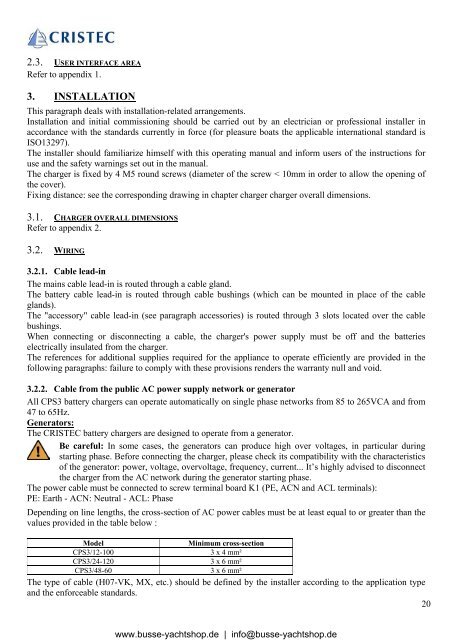
The power cable must be connected to screw terminal board K1 (PE, ACN and ACL terminals):<br />
PE: Earth - ACN: Neutral - ACL: Phase<br />
Depending on line lengths, the cross-section of AC power cables must be at least equal to or greater than the<br />
values provided in the table below :<br />
Model Minimum cross-section<br />
CPS3/12-100 3 x 4 mm²<br />
CPS3/24-120 3 x 6 mm²<br />
CPS3/48-60 3 x 6 mm²<br />
The type of cable (H07-VK, MX, etc.) should be defined by the installer according to the application type<br />
and the enforceable standards.<br />
20<br />
www.busse-yachtshop.de | info@busse-yachtshop.de