TermoRossella Plus DSA – TermoNicoletta DSA TermoRossella ...
TermoRossella Plus DSA – TermoNicoletta DSA TermoRossella ...
TermoRossella Plus DSA – TermoNicoletta DSA TermoRossella ...

Create successful ePaper yourself
Turn your PDF publications into a flip-book with our unique Google optimized e-Paper software.
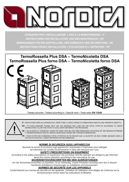
<strong>TermoRossella</strong> <strong>Plus</strong> <strong>DSA</strong> <strong>–</strong> <strong>TermoNicoletta</strong> <strong>DSA</strong><br />
<strong>TermoRossella</strong> <strong>Plus</strong> forno <strong>DSA</strong> <strong>–</strong> <strong>TermoNicoletta</strong> forno <strong>DSA</strong><br />
|<br />
!<br />
ISTRUZIONI PER L’INSTALLAZIONE, L’USO E LA MANUTENZIONE - IT<br />
INSTRUCTIONS FOR INSTALLATION, USE AND MAINTENANCE - EN<br />
ANWEISUNGEN FÜR DIE AUFSTELLUNG, DEN GEBRAUCH UND DIE WARTUNG - DE<br />
INSTRUCTIONS POUR L’INSTALLATION, L’UTILISATION ET L’ENTRETIEN - FR<br />
Testata secondo / Tested according to / Geprüft nach / Testé selon EN 13240<br />
IT <strong>–</strong> PER EVITARE DANNI ALL’APPARECCHIO, RISPETTARE IL CARICO ORARIO DI COMBUSTIBILE INDICATO NEL PRESENTE LIBRETTO.<br />
EN <strong>–</strong> TO AVOID DAMAGES, PLEASE ONLY USE THE MAXIMUM FUEL LOAD FOR THE INITIAL START-UP ACCORDING TO USER'S<br />
INSTRUCTIONS. ALLOW THE STOVE TO COOL DOWN AND REPEAT THE PROCEDURE.<br />
DE <strong>–</strong> UM SCHÄDEN ZU VERMEIDEN, HEIZEN SIE IHREN OFEN BEI DER INBETRIEBNAHME HÖCHSTENS MIT DER BRENNSTOFFMENGE<br />
IT. BEDIENUNGSANLEITUNG AN. DANACH AUSKÜHLEN LASSEN UND VORGANG WIEDERHOLEN.<br />
FR <strong>–</strong> POUR EVITER DES DOMMAGES FAITES ATTENTION DE NE BRULER QUE LA QUANTITE DE BOIS COMME INDIQUEE DANS LA<br />
NOTICE D'UTILISATION. LAISSEZ REFROIDIR PUIS RECOMMENCES.<br />
NORME DI SICUREZZA SUGLI APPARECCHI<br />
Secondo le norme di sicurezza sugli apparecchi l’acquirente e l’esercente sono obbligati<br />
ad informarsi sul corretto funzionamento in base alle istruzioni per l’uso.<br />
SAFETY PRESCRIPTIONS ON EQUIPMENT<br />
According to the safety prescriptions on equipment, the purchaser and the operator are obliged to get informed<br />
about the correct operation according to the instructions for use.<br />
SICHERHEITSVORSCHRIFTEN BEI DEN AUSRÜSTUNGEN<br />
Um die Sicherheitsvorschriften zu beachten, ist es notwendig, unsere Produkte vorsichtig nach den in diesem<br />
Handbuch enthaltenen Anweisungen zu installieren und anzuwenden.<br />
NORMES DE SECURITE SUR LES APPAREILS<br />
Conformément aux normes de sécurité sur les appareils, l’acheteur et l’utilisateur sont obligés de s’informer sur le<br />
fonctionnement correct selon les instructions d’utilisation.
TERMOROSSELLA <strong>Plus</strong> <strong>DSA</strong> / Forno <strong>DSA</strong> <strong>–</strong> TERMONICOLETTA <strong>DSA</strong> / Forno <strong>DSA</strong><br />
DICHIARAZIONE DI CONFORMITA’ DEL COSTRUTTORE<br />
Oggetto: assenza di amianto e cadmio<br />
Si dichiara che tutti i nostri apparecchi vengono assemblati con materiali che non presentano parti di amianto o suoi<br />
derivati e che nel materiale d’apporto utilizzato per le saldature non è presente/utilizzato in nessuna forma il cadmio,<br />
come previsto dalla norma di riferimento.<br />
Oggetto: regolamento CE n. 1935/2004<br />
Si dichiara che in tutti gli apparecchi da noi prodotti, i materiali destinati a venire a contatto con i cibi sono adatti<br />
all’uso alimentari, in conformità al Regolamento CE in oggetto.<br />
DECLARATION OF CONFORMITY OF THE MANUFACTURER<br />
Object: Absence of asbestos and cadmium<br />
We declare that the materials used for the assembly of all our appliances are without asbestos parts or asbestos<br />
derivates and that in the material used for welding, cadmium is not present, as prescribed in relevant norm.<br />
Object: CE n. 1935/2004 regulation.<br />
We declare that in all products we produce, the materials which will get in touch with food are suitable for alimentary<br />
use, according to the a.m. CE regulation.<br />
KONFORMITÄTSERKLÄRUNG DES HERSTELLERS<br />
Betreff: Fehlen von Asbest und Kadmium<br />
Wir bestätigen, dass die verwendeten Materialen oder Teilen für die Herstellung der La Nordica Geräte ohne Asbest<br />
und Derivat sind und auch das Lot für das Schweißen immer ohne Kadmium ist.<br />
Betreff: Ordnung CE n. 1935/2004. Wir erklären in alleiniger Verantwortung, dass die Materialien der Teile, die für<br />
den Kontakt mit Lebensmitteln vorgesehen sind, für die Nahrungsbenutzung geeignet sind und der Richtlinien CE n.<br />
1935/2004 erfüllen<br />
DECLARATION DE CONFORMITE DU FABRICANT<br />
Objet: absence d’amiante et de cadmium<br />
Nous déclarons que tous nos appareils sont fabriqués avec des matériaux qui ne présentent pas de pièces en<br />
amiante ou ses dérivés et que le matériel d’apport utilisé pour les soudures ne contient/n’utilise sous aucune forme du<br />
cadmium, comme prévu dans la norme de référence.<br />
Objet: Règlement CE n. 1935/2004<br />
Nous déclarons que sur tous nos appareils, les matériaux destinés à entrer en contact avec les aliments sont<br />
adéquats à l’usage alimentaire, conformément au Règlement CE en objet.<br />
2 7197100 Rev.05 <strong>–</strong> IT <strong>–</strong> EN <strong>–</strong> DE <strong>–</strong> FR
TERMOROSSELLA <strong>Plus</strong> <strong>DSA</strong> / Forno <strong>DSA</strong> <strong>–</strong> TERMONICOLETTA <strong>DSA</strong> / Forno <strong>DSA</strong><br />
INDICE IT<br />
1. DATI TECNICI ............................................................................................................................................................................ 5<br />
2. DESCRIZIONE TECNICA .......................................................................................................................................................... 6<br />
3. NORME PER L’INSTALLAZIONE .............................................................................................................................................. 6<br />
3.1. Vaso di espansione APERTO ............................................................................................................................................ 7<br />
3.2. Vaso di espansione CHIUSO ............................................................................................................................................ 8<br />
3.3. VALVOLA MISCELATRICE TERMOSTATICA AUTOMATICA (OPTIONAL) .................................................................... 8<br />
3.4. VALVOLA SCARICO TERMICO (OPTIONAL) .................................................................................................................. 8<br />
4. SICUREZZA ANTINCENDIO ..................................................................................................................................................... 9<br />
4.1. PRONTO INTERVENTO ................................................................................................................................................. 10<br />
5. CANNA FUMARIA .................................................................................................................................................................... 10<br />
5.1. POSIZIONE DEL COMIGNOLO ...................................................................................................................................... 10<br />
6. COLLEGAMENTO AL CAMINO ............................................................................................................................................... 12<br />
7. AFFLUSSO D’ARIA NEL LUOGO D’INSTALLAZIONE DURANTE LA COMBUSTIONE ........................................................ 12<br />
8. COMBUSTIBILI AMMESSI / NON AMMESSI .......................................................................................................................... 13<br />
9. ACCENSIONE.......................................................................................................................................................................... 13<br />
10. FUNZIONAMENTO NORMALE ........................................................................................................................................... 14<br />
11. USO DEL FORNO (dove presente) ..................................................................................................................................... 15<br />
12. MANCANZA DI ENERGIA ELETTRICA .............................................................................................................................. 15<br />
13. FUNZIONAMENTO NEI PERIODI DI TRANSIZIONE ......................................................................................................... 15<br />
13.1. UTILIZZO COME NORMALE STUFA. ............................................................................................................................ 15<br />
14. MANUTENZIONE E CURA .................................................................................................................................................. 15<br />
14.1. PULIZIA CANNA FUMARIA ............................................................................................................................................ 15<br />
14.2. PULIZIA VETRO .............................................................................................................................................................. 16<br />
14.3. PULIZIA CASSETTO CENERE ....................................................................................................................................... 16<br />
14.4. MANUTENZIONE DELL’IMPIANTO IDRAULICO ........................................................................................................... 16<br />
15. FERMO ESTIVO .................................................................................................................................................................. 16<br />
16. COLLEGAMENTO ALLA CANNA FUMARIA DI UN CAMINETTO O FOCOLARE APERTO .............................................. 17<br />
18. SCHEDA TECNICA / TECHNICAL DATA SHEETS / TECHNISCHE PROTOKOLLE ......................................................... 56<br />
19. CERAMICHE / CERAMICS / KACHELN / FAIENCES / MONTAGE DES FAIENCES (TERMONICOLETTA) .................... 58<br />
20. SCHEMA D’INSTALLAZIONE / INSTALLATION DIAGRAM / INSTALLATION SCHEME ................................................... 59<br />
INDEX EN<br />
1. TECHNICAL DATA .................................................................................................................................................................. 18<br />
2. TECHNICAL DESCRIPTION ................................................................................................................................................... 19<br />
3. REGULATIONS FOR INSTALLATION ..................................................................................................................................... 19<br />
3.1. OPEN expansion VESSEL system .................................................................................................................................. 20<br />
3.2. CLOSED expansion VESSEL system ............................................................................................................................. 20<br />
3.3. AUTOMATIC THERMOSTATIC MIXER VALVE (OPTIONAL) ........................................................................................ 21<br />
3.4. HEAT DISCHARGE VALVE (OPTIONAL) ....................................................................................................................... 21<br />
4. FIRE RISK SAFETY ................................................................................................................................................................. 22<br />
4.1. EMERGENCY PLAN ....................................................................................................................................................... 22<br />
5. FLUE ........................................................................................................................................................................................ 23<br />
5.1. POSITION OF THE CHIMNEY POT ............................................................................................................................... 23<br />
6. CONNECTION TO THE CHIMNEY .......................................................................................................................................... 25<br />
7. FLOW OF AIR IN THE PLACE OF INSTALLATION DURING COMBUSTION ........................................................................ 25<br />
8. ACCEPTED / UNACCEPTED FUELS ...................................................................................................................................... 25<br />
9. IGNITION ................................................................................................................................................................................. 26<br />
10. NORMAL FUNCTIONING .................................................................................................................................................... 27<br />
11. OVEN USE (if present) ........................................................................................................................................................ 27<br />
12. POWER CUT ....................................................................................................................................................................... 27<br />
13. FUNCTIONING IN TRANSITION PERIODS ........................................................................................................................ 28<br />
13.1. USE AS A NORMAL STOVE. .......................................................................................................................................... 28<br />
14. MAINTENANCE AND CARE ............................................................................................................................................... 28<br />
14.1. CLEANING THE FLUE .................................................................................................................................................... 28<br />
14.2. CLEANING THE GLASS ................................................................................................................................................. 28<br />
14.3. CLEANING THE ASH BOX ............................................................................................................................................. 28<br />
14.4. MAINTENANCE ON THE WATER SYSTEM .................................................................................................................. 29<br />
15. SUMMER SHUTDOWN ....................................................................................................................................................... 29<br />
16. CONNECTION TO THE FLUE OF AN OPEN CHIMNEY OF FIREPLACE ......................................................................... 29<br />
18. SCHEDA TECNICA / TECHNICAL DATA SHEETS / TECHNISCHE PROTOKOLLE ......................................................... 56<br />
19. CERAMICHE / CERAMICS / KACHELN / FAIENCES / MONTAGE DES FAIENCES (TERMONICOLETTA) .................... 58<br />
20. SCHEMA D’INSTALLAZIONE / INSTALLATION DIAGRAM / INSTALLATION SCHEME ................................................... 59<br />
7197100 Rev.05 <strong>–</strong> IT <strong>–</strong> EN <strong>–</strong> DE <strong>–</strong> FR 3
TERMOROSSELLA <strong>Plus</strong> <strong>DSA</strong> / Forno <strong>DSA</strong> <strong>–</strong> TERMONICOLETTA <strong>DSA</strong> / Forno <strong>DSA</strong><br />
INHALTSVERZEICHNIS DE<br />
1. TECHNISCHE DATEN ............................................................................................................................................................. 30<br />
2. TECHNISCHE BESCHREIBUNG ............................................................................................................................................ 31<br />
3. INSTALLATIONSVORSCHRIFTEN ......................................................................................................................................... 31<br />
3.1. OFFENEM Ausdehnungsgefäß ....................................................................................................................................... 32<br />
3.2. GESCHLOSSENEM Ausdehnungsgefäß ........................................................................................................................ 33<br />
3.3. AUTOMATISCHES THERMOSTAT- MISCHVENTIL (OPTIONAL)- ABB. 2 ................................................................... 33<br />
3.4. WÄRMEABLASSVENTIL (NICHT IM LIEFERUMFANG) - ABB. 3 .................................................................................. 34<br />
4. BRANDSCHUTZ ...................................................................................................................................................................... 34<br />
4.1. SOFORTIGES EINSCHREITEN ..................................................................................................................................... 35<br />
5. RAUCHABZUG ........................................................................................................................................................................ 35<br />
5.1. SCHORNSTEINPOSITION ............................................................................................................................................. 36<br />
6. ANSCHLUSS AN DEN SCHORNSTEIN .................................................................................................................................. 37<br />
7. LUFTZUSTROM AM INSTALLATIONSORT WÄHREND DER VERBRENNUNG ................................................................... 37<br />
8. ZULÄSSIGE / UNZULÄSSIGE BRENNSTOFFE ..................................................................................................................... 38<br />
9. ANZÜNDEN ............................................................................................................................................................................. 38<br />
10. NORMALER BETRIEB ........................................................................................................................................................ 39<br />
11. BENUTZUNG DES BACKOFENS ....................................................................................................................................... 40<br />
12. STROMAUSFALL ................................................................................................................................................................ 40<br />
13. BETRIEB IN DER ÜBERGANGSZEIT ................................................................................................................................. 40<br />
13.1. VERWENDUNG ALS NORMALER OFEN ...................................................................................................................... 40<br />
14. INSTANDHALTUNG UND PFLEGE .................................................................................................................................... 41<br />
14.1. REINIGUNG DES RAUCHABZUGS ............................................................................................................................... 41<br />
14.2. REINIGUNG DER GLASSCHEIBE ................................................................................................................................. 41<br />
14.3. REINIGUNG DES ASCHEKASTENS .............................................................................................................................. 41<br />
14.4. WARTUNG DER HYDRAULIKANLAGE.......................................................................................................................... 41<br />
15. STILLSTAND IM SOMMER ................................................................................................................................................. 42<br />
16. ANSCHLUSS AN DEN RAUCHABZUG EINES OFFENEN KAMINS .................................................................................. 42<br />
18. SCHEDA TECNICA / TECHNICAL DATA SHEETS / TECHNISCHE PROTOKOLLE ......................................................... 56<br />
19. CERAMICHE / CERAMICS / KACHELN / FAIENCES / MONTAGE DES FAIENCES (TERMONICOLETTA) .................... 58<br />
20. SCHEMA D’INSTALLAZIONE / INSTALLATION DIAGRAM / INSTALLATION SCHEME ................................................... 59<br />
SOMMAIRE FR<br />
1. DONNES TECHNIQUES ......................................................................................................................................................... 43<br />
2. DESCRIPTION TECHNIQUE ................................................................................................................................................... 44<br />
3. NORMES POUR L’INSTALLATION ......................................................................................................................................... 44<br />
3.1. Vase d’expansion OUVERT ............................................................................................................................................ 45<br />
3.2. Vase d’expansion FERME ............................................................................................................................................... 46<br />
3.3. VANNE MELANGEUSE THERMOSTATIQUE AUTOMATIQUE (OPTIONNEL) ............................................................. 46<br />
3.4. VANNE DE DECHARGE THERMIQUE (OPTIONNEL)................................................................................................... 46<br />
4. SECURITE ANTINCENDIE ...................................................................................................................................................... 47<br />
4.1. INTERVENTION EN CAS D’URGENCE ......................................................................................................................... 48<br />
5. CONDUIT DE FUMEE ............................................................................................................................................................. 48<br />
5.1. POSITION DU TERMINAL DU CONDUIT DE FUMEE ................................................................................................... 48<br />
6. RACCORDEMENT AU CONDUIT DE FUMEE ........................................................................................................................ 50<br />
7. AMENEE D’AIR DANS LE LIEU DE LA MISE EN PLACE DURANT LA COMBUSTION ........................................................ 50<br />
8. COMBUSTIBLES ADMIS / NON ADMIS .................................................................................................................................. 51<br />
9. ALLUMAGE .............................................................................................................................................................................. 51<br />
10. FONCTIONNEMENT NORMAL ........................................................................................................................................... 52<br />
11. UTILISATION DU FOUR (où présente) ............................................................................................................................... 53<br />
12. ABSENCE D’ENERGIE ELECTRIQUE ............................................................................................................................... 53<br />
13. FONCTIONNEMENT PENDANT LES PERIODES DE TRANSITION ................................................................................. 53<br />
13.1. UTILISATION COMME UN POELE NORMAL ................................................................................................................ 53<br />
14. ENTRETIEN ET SOIN ......................................................................................................................................................... 53<br />
14.1. NETTOYAGE DU CONDUIT DE FUMEE........................................................................................................................ 54<br />
14.2. NETTOYAGE DE LA VITRE ............................................................................................................................................ 54<br />
14.3. NETTOYAGE DU CENDRIER ......................................................................................................................................... 54<br />
14.4. ENTRETIEN DE L’INSTALLATION HYDRAULIQUE ...................................................................................................... 54<br />
15. ARRET PENDANT L’ETE .................................................................................................................................................... 54<br />
16. CONNEXION AU CONDUIT DE FUMEE D’UNE CHEMINEE OU D’UN FOYER OUVERT ................................................ 55<br />
18. SCHEDA TECNICA / TECHNICAL DATA SHEETS / TECHNISCHE PROTOKOLLE ......................................................... 56<br />
19. CERAMICHE / CERAMICS / KACHELN / FAIENCES / MONTAGE DES FAIENCES (TERMONICOLETTA) .................... 58<br />
20. SCHEMA D’INSTALLAZIONE / INSTALLATION DIAGRAM / INSTALLATION SCHEME ................................................... 59<br />
4 7197100 Rev.05 <strong>–</strong> IT <strong>–</strong> EN <strong>–</strong> DE <strong>–</strong> FR
TERMOROSSELLA <strong>Plus</strong> <strong>DSA</strong> / Forno <strong>DSA</strong> <strong>–</strong> TERMONICOLETTA <strong>DSA</strong> / Forno <strong>DSA</strong><br />
1. DATI TECNICI<br />
Definizione: termostufa secondo EN 13240<br />
<strong>DSA</strong><br />
TERMO<br />
ROSSELLA<br />
<strong>Plus</strong><br />
TERMO<br />
ROSSELLA<br />
<strong>Plus</strong> FORNO<br />
TERMO<br />
NICOLETTA<br />
TERMO<br />
NICOLETTA<br />
FORNO<br />
Potenza termica globale in kW 17.3 16.7 17.3 16.7<br />
Potenza termica utile in kW 13.5 13.5 13.5 13.5<br />
Potenza resa all’acqua in kW 10.5 10.5 10.5 10.5<br />
Potenza resa all’ambiente in kW 3 3 3 3<br />
Consumo orario legna in kg/h<br />
(legna con 20% umidità)<br />
4 3.9 4 3.9<br />
Rendimento in % 78.2 81,1 78.2 81,1<br />
CO misurato al 13% di ossigeno in % 0.10 0.07 0.10 0.07<br />
Diametro tubo uscita fumi in mm 130 130 130 130<br />
Diametro canna fumaria in mm ∗<br />
5m 220x220<br />
Ø220<br />
4m 250x250<br />
Ø250<br />
5m 220x220<br />
Ø220<br />
4m 250x250<br />
Ø250<br />
5m 220x220<br />
Ø220<br />
4m 250x250<br />
Ø250<br />
5m 220x220<br />
Ø220<br />
4m 250x250<br />
Ø250<br />
Contenuto di acqua nella caldaia in litri (L) 18.5 18.5 18.5 18.5<br />
Depressione al camino in (mm H2O) 1.7 / 2 1.7 / 2 1.7 / 2 1.7 / 2<br />
Diametro raccordi mandata e ritorno in pollici gas 1”g F 1”g F 1”g F 1”g F<br />
Sezione presa aria esterna Ø in mm 200 200 200 200<br />
Emissione gas di scarico in g/s <strong>–</strong> legna 13.5 14.7 13.5 14.7<br />
Temperatura gas di scarico nel mezzo in °C -<br />
legna<br />
270 214 270 214<br />
Temperatura ottimale di esercizio in °C 70 - 75 70 - 75 70 - 75 70 - 75<br />
Pressione max d’esercizio in bar VEA1,5 <strong>–</strong> VEC3 VEA1,5 <strong>–</strong> VEC3 VEA1,5 - VEC3 VEA1,5 - VEC3<br />
Dimensioni apertura focolare in mm (L x H) 355x245 345x245 355x245 345x245<br />
Dimensioni corpo focolare / testata focolare in<br />
mm (L x H x P)<br />
307x245x345 307x318x345 307x245x345 307x318x345<br />
Dimensioni forno in mm (L x H x P) - 330x300x370 - 330x300x370<br />
Tipo di griglia Griglia piana, girevole dall’esterno<br />
Altezza termostufa in mm 915 1359 980 1423<br />
Larghezza termostufa in mm 559 559 587 587<br />
Profondità termostufa (con maniglie) in mm 533 533 575 575<br />
Peso in Kg 160 - 175 218 <strong>–</strong> 242 183 254<br />
Distanze di sicurezza antincendio Capitolo 4<br />
∗ Diametro 200 mm utilizzabile con canna fumaria non inferiore a 6 m<br />
La capacità di riscaldamento dei locali secondo EN 13240, per edifici il cui isolamento termico non corrisponde ai<br />
requisiti del Regolamento sugli isolamenti termici, è :<br />
(30 Kcal/h x m 3 ) - tipo di costruzione favorevole: 390 m³<br />
(40 Kcal/h x m 3 ) - tipo di costruzione meno favorevole: 292 m³<br />
(50 Kcal/h x m 3 ) - tipo di costruzione sfavorevole: 233 m³<br />
Con un isolamento termico adeguato alle disposizioni sulla protezione del calore il volume di riscaldamento è<br />
maggiore. Con un riscaldamento temporaneo, in caso di interruzioni superiori a 8h, la capacità di riscaldamento<br />
diminuisce del 25% circa.<br />
7197100 Rev.05 <strong>–</strong> IT 5
2. DESCRIZIONE TECNICA<br />
TERMOROSSELLA <strong>Plus</strong> <strong>DSA</strong> / Forno <strong>DSA</strong> <strong>–</strong> TERMONICOLETTA <strong>DSA</strong> / Forno <strong>DSA</strong><br />
Le termostufe La Nordica si addicono a riscaldare spazi abitativi dotati di un impianto di riscaldamento centralizzato<br />
costituito da radiatori o da termoconvettori sostituendo del tutto o in parte la tradizionale caldaia a gas o gasolio. Esse<br />
sono ideali per appartamenti di vacanza e case del fine settimana oppure come riscaldamento ausiliario durante tutto<br />
l’anno. Come combustibili vengono utilizzati ceppi di legna.<br />
Il focolare si trova all’interno della caldaia costruita con acciaio di 4 mm di spessore e rinforzata con chiodi saldati.<br />
Nella caldaia circola l’acqua dell’impianto di riscaldamento la quale assorbe il calore prodotto nel focolare.<br />
All’interno del focolare si trova una griglia girevole estraibile.<br />
Il focolare è dotato di una porta panoramica con vetro ceramico (resistente fino a 700°C). Questo cons ente<br />
un’affascinante vista sulle fiamme ardenti. Inoltre viene così impedita ogni possibile fuoriuscita di scintille e fumo.<br />
Il riscaldamento dell’ambiente avviene:<br />
a) per irraggiamento: attraverso il vetro panoramico e le superfici esterne<br />
B<br />
calde della termostufa viene irraggiato il calore nell’ambiente;<br />
b) per conduzione: mediante i radiatori o termoconvettori dell’impianto<br />
centralizzato alimentati dall’acqua calda prodotta dalla Termostufa<br />
stessa.<br />
La termostufa è dotata di registri per l’aria primaria e secondaria, con i quali viene<br />
regolata l’aria di combustione.<br />
Registro aria PRIMARIA (leva inferiore) (Pos.A Figura 1)<br />
Con il registro posto in basso a SX della porta del focolare viene regolato il A<br />
passaggio dell’aria attraverso il cassetto cenere e la griglia in direzione del<br />
combustibile. L’aria primaria è necessaria per il processo di combustione. Il<br />
cassetto cenere deve essere svuotato regolarmente, in modo che la cenere non<br />
possa ostacolare l’entrata dell’aria primaria per la combustione. Attraverso l’aria<br />
Figura 1<br />
primaria viene anche mantenuto vivo il fuoco.<br />
Durante la combustione di legna, il registro dell’aria primaria deve essere aperto solo un poco, poiché altrimenti la<br />
legna arde velocemente e la termostufa si può surriscaldare.<br />
Con la leva tutta estratta il registro è aperto, con la leva inserita il registro è chiuso.<br />
Registro aria SECONDARIA ( leva superiore ) (Pos.B Figura 1)<br />
Sopra la porta del focolare si trova il registro dell’aria secondaria. Questo registro deve essere aperto (quindi la leva<br />
deve essere spostata verso destra), in particolare per la combustione di legna, cosicché il carbonio incombusto può<br />
subire una post-combustione. Vedi paragrafo 10. Attraverso questo registro è possibile regolare l’andamento della<br />
Termostufa.<br />
Lasciandolo leggermente aperto, a seconda del tiraggio del camino, è possibile mantenere il vetro pulito.<br />
3. NORME PER L’INSTALLAZIONE<br />
L’installazione della termostufa e degli equipaggiamenti ausiliari, relativi all’impianto di riscaldamento, deve essere<br />
conforme a tutte le Norme e Regolamentazioni attuali ed a quanto previsto dalla Legge.<br />
L’installazione, i relativi collegamenti dell’impianto, la messa in servizio e la verifica del corretto funzionamento<br />
devono essere eseguiti a regola d’arte da personale professionalmente autorizzato nel pieno rispetto delle norme<br />
vigenti, sia nazionali, regionali, provinciali e comunali presenti nel paese in cui è stato installato l’apparecchio, nonché<br />
delle presenti istruzioni.<br />
L’installazione deve essere eseguita da personale autorizzato, che dovrà rilasciare all’acquirente una dichiarazione di<br />
conformità dell’impianto, il quale si assumerà l’intera responsabilità dell’installazione definitiva e del conseguente<br />
buon funzionamento del prodotto installato.<br />
Non vi sarà responsabilità da parte di La NORDICA S.p.A. in caso di mancato rispetto di tali precauzioni.<br />
Prima dell’installazione, si consiglia di effettuare un lavaggio accurato di tutte le tubazioni dell’impianto onde<br />
rimuovere eventuali residui che potrebbero compromettere il buon funzionamento dell’apparecchio.<br />
IMPORTANTE:<br />
a) In caso di fuoriuscite d’acqua chiudere l’alimentazione idrica ed avvisare con sollecitudine il servizio tecnico di<br />
assistenza;<br />
b) La pressione di esercizio dell’impianto deve essere periodicamente controllata.<br />
c) In caso di non utilizzo della caldaia per un lungo periodo è consigliabile l’intervento del servizio tecnico di<br />
assistenza per effettuare almeno le seguenti operazioni:<br />
- chiudere i rubinetti dell’acqua sia dell’impianto termico sia del sanitario;<br />
- svuotare l’impianto termico e sanitario se c’è rischio di gelo.<br />
La Nordica S.p.A. declina ogni responsabilità per danni a cose e/o persone provocati dall’impianto. Inoltre<br />
non è responsabile del prodotto modificato senza autorizzazione e tanto meno per l’uso di ricambi non<br />
originali.<br />
6 7197100 Rev.05 <strong>–</strong> IT
TERMOROSSELLA <strong>Plus</strong> <strong>DSA</strong> / Forno <strong>DSA</strong> <strong>–</strong> TERMONICOLETTA <strong>DSA</strong> / Forno <strong>DSA</strong><br />
Il Vostro abituale spazzacamino di zona deve essere informato sull’installazione della termostufa, affinché possa<br />
verificarne il regolare collegamento alla canna fumaria ed il grado di efficienza di quest’ultima.<br />
NON SI POSSONO EFFETTUARE MODIFICHE ALL’APPARECCHIO.<br />
Prima dell’installazione, verificate se il Vostro pavimento può sopportare il peso della Termostufa.<br />
ATTENZIONE: assicurarsi che l’apparecchio sia posto perfettamente in piano e che il diametro del tubo di<br />
scarico dei fumi sia quello richiesto.<br />
Non è concesso il collegamento di più stufe allo stesso camino.<br />
Vi consigliamo di far verificare dal Vostro abituale spazzacamino di zona sia il collegamento al camino sia il sufficiente<br />
afflusso d’aria per la combustione nel luogo d’installazione.<br />
Il diametro dell’apertura per il collegamento al camino deve corrispondere per lo meno al diametro del tubo fumo.<br />
L’apertura dovrebbe essere dotata di una connessione a muro per l’inserimento del tubo di scarico e di un rosone.<br />
Le termostufe modello <strong>DSA</strong> possono essere installate sia in un impianto a VASO di espansione APERTO (cap.3.1)<br />
sia in un impianto a VASO di espansione CHIUSO (cap.3.2).<br />
3.1. Vaso di espansione APERTO<br />
L’impianto con vaso di espansione APERTO, deve essere OBBLIGATORIAMENTE provvisto di:<br />
1. VASO DI ESPANSIONE APERTO: vaso avente una capacità pari al 10 % del contenuto d’acqua totale del<br />
termoprodotto e dell’impianto. Il vaso va posizionato nel punto più alto dell’impianto almeno 2 m sopra il radiatore<br />
posto al livello più alto.<br />
2. TUBO DI SICUREZZA : tubo che collega per la via più breve, senza tratti discendenti o sifonanti la mandata del<br />
termoprodotto con la parte superiore del vaso di espansione aperto. Il tubo di sicurezza deve avere la sezione<br />
minima interna di 1”gas.<br />
3. TUBO DI CARICO : tubo che collega il fondo del vaso di espansione aperto con il tubo di ritorno dell’impianto. La<br />
sezione minima deve essere di ¾”gas. Tutti questi elementi non devono per nessuna ragione avere organi di<br />
intercettazione interposti che possano accidentalmente escluderli e devono essere posizionati in ambienti non<br />
esposti al gelo poiché, se dovessero gelare, si potrebbe verificare la rottura o addirittura l’esplosione del corpo<br />
caldaia. In caso di esposizione al gelo sarà opportuno aggiungere all’acqua dell’impianto una adeguata<br />
percentuale di liquido antigelo che consentirà di eliminare completamente il problema. In nessun modo ci dovrà<br />
essere circolazione d’acqua nel vaso di espansione aperto fra il tubo di sicurezza ed il tubo di carico. Questa<br />
provocherebbe l’ossigenazione dell’acqua e la conseguente corrosione del termoprodotto e dell’impianto in tempi<br />
molto brevi<br />
4. VALVOLA DI SCARICO TERMICO: costituisce una ulteriore sicurezza positiva in grado di prevenire l’ebollizione<br />
anche in assenza di energia elettrica. E’ costituita da un corpo valvola simile ad una valvola di sicurezza a<br />
pressione che, a differenza di questa, si apre al raggiungimento di una temperatura pretarata ( di solito 94 <strong>–</strong> 95° C)<br />
scaricando dalla mandata dell’impianto acqua calda che verrà sostituita con altrettanta acqua fredda proveniente<br />
attraverso il tubo di carico del vaso di espansione aperto smaltendo in questo modo il calore eccessivo.<br />
5. VALVOLA DI SICUREZZA da 1,5bar: la massima pressione di esercizio ammessa per l’impianto è di 1,5bar (pari<br />
a 15m di colonna d’acqua), pressioni superiori possono provocare deformazioni e rotture del corpo caldaia.<br />
6. DISPOSITIVI DI SICUREZZA previsti dalla Normativa vigente in materia.<br />
7. POMPA DI CIRCOLAZIONE: deve essere preferibilmente montata sul ritorno per evitare che possa disinnescarsi<br />
a temperature dell’acqua molto elevate, accertarsi però che non faccia circolare l’acqua nel vaso di espansione<br />
aperto altrimenti provocherebbe una continua ossigenazione dell’acqua con conseguente, rapida, corrosione del<br />
corpo caldaia. La sua prevalenza deve essere tale da non provocare una circolazione forzata nel vaso di<br />
espansione aperto. Deve inoltre essere collegata ad un termostato o alla centralina elettronica fornita come<br />
OPTIONAL.<br />
8. VALVOLA MISCELATRICE TERMOSTATICA AUTOMATICA <strong>–</strong> (vedi capitolo 3.3)<br />
IMPORTANTE: i sensori di sicurezza della temperatura devono essere a bordo macchina o a una distanza non<br />
maggiore di 30 cm dal collegamento di mandata del termoprodotto.<br />
Qualora i termoprodotti non siano provvisti di tutti i dispostivi, quelli mancanti possono essere installati sulla tubazione<br />
di mandata del termoprodotto entro una distanza dal termoprodotto non maggiore di 1 m.<br />
ATTENZIONE: Per nessuna ragione si deve accendere il fuoco se prima l’impianto non sia stato<br />
completamente riempito d’acqua; il farlo comporterebbe un danneggiamento gravissimo di tutta la<br />
struttura. Il riempimento dell’impianto deve essere fatto tramite il tubo di carico direttamente dalla vaschetta<br />
del vaso aperto in modo da evitare che una eccessiva pressione della rete idrica deformi il corpo caldaia della<br />
termostufa.<br />
L’impianto va tenuto costantemente pieno d’acqua anche nei periodi in cui non è richiesto l’uso della termostufa.<br />
Durante il periodo invernale un’eventuale non attività va affrontata con l’aggiunta di sostanze antigelo.<br />
7197100 Rev.05 <strong>–</strong> IT 7
3.2. Vaso di espansione CHIUSO<br />
TERMOROSSELLA <strong>Plus</strong> <strong>DSA</strong> / Forno <strong>DSA</strong> <strong>–</strong> TERMONICOLETTA <strong>DSA</strong> / Forno <strong>DSA</strong><br />
L’impianto con vaso di espansione CHIUSO, deve essere OBBLIGATORIAMENTE provvisto di:<br />
1. VALVOLA DI SICUREZZA da 3 bar: la massima pressione di esercizio ammessa per l’impianto è di 3 bar (pari<br />
a 30 m di colonna d’acqua), pressioni superiori possono provocare deformazioni e rotture del corpo caldaia.<br />
2. VALVOLA MISCELATRICE TERMOSTATICA AUTOMATICA <strong>–</strong> (vedi capitolo 3.3)<br />
3. VALVOLA DI SCARICO TERMICO o SCARICO DI SICUREZZA TERMICA (a sicurezza positiva, cioè in caso di<br />
guasto della valvola questa continua a scaricare lo stesso)<br />
4. VASO DI ESPANSIONE CHIUSO<br />
5. TERMOSTATO DI COMANDO DEL CIRCOLATORE<br />
6. TERMOSTATO DI ATTIVAZIONE DELL’ALLARME ACUSTICO<br />
7. ALLARME ACUSTICO<br />
8. INDICATORE DI TEMPERATURA<br />
9. INDICATORE DI PRESSIONE<br />
10. SISTEMA DI CIRCOLAZIONE<br />
IMPORTANTE: i sensori di sicurezza della temperatura devono essere a bordo macchina o a una distanza non<br />
maggiore di 30 cm dal collegamento di mandata del termoprodotto. Qualora i termoprodotti non siano provvisti di tutti<br />
i dispostivi, quelli mancanti possono essere installati sulla tubazione di mandata del termoprodotto entro una distanza<br />
dal termoprodotto non maggiore di 1 m.<br />
OBBLIGATORIAMENTE i termoprodotti per il riscaldamento di tipo domestico inseriti in impianti di riscaldamento a<br />
VASO CHIUSO devono essere dotati, al loro interno, di un circuito di raffreddamento predisposto dal costruttore<br />
dell’apparecchio, attivato da una valvola di sicurezza termica (vedi capitolo 3.4) che non richieda energia<br />
ausiliaria e tale da garantire che non venga superata la temperatura limite imposta dalla norma. Il collegamento tra<br />
il gruppo di alimentazione e la valvola deve essere privo di intercettazioni. La pressione a monte del circuito di<br />
raffreddamento deve essere di almeno 1,5 bar.<br />
3.3. VALVOLA MISCELATRICE TERMOSTATICA AUTOMATICA (OPTIONAL)<br />
La valvola miscelatrice termostatica automatica trova applicazione nei generatori termici a combustibile solido in<br />
quanto previene il ritorno di acqua fredda nello scambiatore.<br />
Le tratte 1 e 3 sono sempre aperte e, assieme alla pompa installata sul ritorno (Figura 2 R), garantiscono la<br />
circolazione dell’acqua all’interno dello scambiatore della caldaia a biomassa (CB).<br />
Una elevata temperatura di ritorno permette di migliorare l’efficienza, riduce la formazione di condensa dei fumi e<br />
allunga la vita della caldaia.<br />
Le valvole in commercio presentano svariate tarature, La NORDICA consiglia l’utilizzo del modello 55°C con<br />
connessioni idrauliche da 1”. Una volta raggiunta la temperatura di taratura della valvola, viene aperta la tratta 2 e<br />
l’acqua della caldaia va all’impianto attraverso la mandata (M).<br />
IMPORTANTE la mancata installazione del dispositivo fa decadere la garanzia dello scambiare di calore.<br />
CB<br />
TERMOPRODOTTO<br />
3.4. VALVOLA SCARICO TERMICO (OPTIONAL)<br />
55°<br />
Figura 2<br />
I termoprodotti a combustibile solido devono essere installati con le sicurezze previste dalle vigenti leggi in materia.<br />
A tale scopo la termostufa è munita di uno serpentino di scarico termico.<br />
Il serpentino di scarico termico dovrà essere collegato da un lato alla rete idrica (Figura 3 A) e dall’altro alla rete di<br />
drenaggio (C). La valvola di scarico termico, il cui bulbo andrà collegato all’attacco B, al raggiungimento della<br />
temperatura di sicurezza abilita l’ingresso di acqua fredda nel serpentino contenuto nella caldaia, scaricando<br />
l’eccesso termico tramite il tubo C verso uno scarico opportunamente installato.<br />
La pressione a monte del circuito di raffreddamento deve essere di almeno 1,5 bar.<br />
8 7197100 Rev.05 <strong>–</strong> IT<br />
1<br />
3<br />
2<br />
M<br />
R
TERMOROSSELLA <strong>Plus</strong> <strong>DSA</strong> / Forno <strong>DSA</strong> <strong>–</strong> TERMONICOLETTA <strong>DSA</strong> / Forno <strong>DSA</strong><br />
A<br />
4. SICUREZZA ANTINCENDIO<br />
B<br />
Nell’installazione della termostufa devono essere osservate le seguenti misure di sicurezza:<br />
a) Al fine di assicurare un sufficiente isolamento termico, rispettare la distanza minima di sicurezza dal retro e da<br />
entrambi i lati da elementi costruttivi ed oggetti infiammabili e sensibili al calore (mobili, rivestimenti di legno,<br />
stoffe ecc.) (vedi Figura 4 A). Tutte le distanze minime di sicurezza sono indicate sulla targhetta tecnica del<br />
prodotto e NON si deve scendere al di sotto dei valori indicati.<br />
b) davanti alla porta del focolare, nell’area di radiazione della stessa, non deve esserci alcun oggetto o materiale di<br />
costruzione infiammabile e sensibile al calore a meno di 100 cm di distanza. Tale distanza può essere ridotta a<br />
40 cm qualora venga installata una protezione, retroventilata e resistente al calore, davanti all’intero componente<br />
da proteggere.<br />
c) qualora il prodotto venga installato su un pavimento di materiale infiammabile, bisogna prevedere un sottofondo<br />
ignifugo. I pavimenti in materiale infiammabile, come moquette, parquet o sughero etc., devono essere<br />
sostituiti da uno strato di materiale non infiammabile, ad esempio ceramica, pietra, vetro o acciaio etc.<br />
(dimensioni secondo l’ordinamento regionale). Il sottofondo deve sporgere frontalmente di almeno 50 cm e<br />
lateralmente di almeno 30 cm oltre all’apertura della porta di carico (vedi Figura 4 B).<br />
d) sopra al prodotto non devono essere presenti componenti infiammabili (es. mobili - pensili).<br />
A B<br />
Figura 3<br />
Figura 4<br />
La termostufa deve funzionare esclusivamente con il cassetto cenere inserito. I residui solidi della combustione<br />
(ceneri) devono essere raccolti in un contenitore ermetico e resistente al fuoco. La termostufa non deve mai essere<br />
accesa in presenza di emissioni gassose o vapori (per esempio colla per linoleum, benzina ecc.). Non depositate<br />
materiali infiammabili nelle vicinanze della termostufa.<br />
Durante la combustione viene sprigionata energia termica che comporta un marcato riscaldamento delle superfici,<br />
della porta e del vetro del focolare, delle maniglie delle porte o di comando, del tubo fumi ed eventualmente della<br />
parte anteriore dell’apparecchio. Evitate il contatto con tali elementi senza un corrispondente abbigliamento protettivo<br />
o senza utensili accessori (guanti resistenti al calore, dispositivi di comando).<br />
Fate in modo che i bambini siano consapevoli di questi pericoli e teneteli lontani dal focolare durante il suo<br />
funzionamento.<br />
Quando si utilizza un combustibile errato o troppo umido si potrebbero formare dei depositi (creosoto) nella canna<br />
fumaria con possibile incendio della canna fumaria stessa.<br />
7197100 Rev.05 <strong>–</strong> IT 9<br />
C<br />
30<br />
30<br />
A<br />
B
4.1. PRONTO INTERVENTO<br />
TERMOROSSELLA <strong>Plus</strong> <strong>DSA</strong> / Forno <strong>DSA</strong> <strong>–</strong> TERMONICOLETTA <strong>DSA</strong> / Forno <strong>DSA</strong><br />
Se si manifesta un incendio nel collegamento o nella canna fumaria :<br />
a) Chiudere la porta di caricamento e del cassetto cenere.<br />
b) Chiudere i registri dell’aria comburente<br />
c) Spegnere tramite l’uso di estintori ad anidride carbonica ( CO2 a polveri )<br />
d) Richiedere l’immediato intervento dei Vigili del Fuoco<br />
Non spegnere il fuoco con l’uso di getti d’acqua.<br />
Quando la canna fumaria smette di bruciare, farla verificare da uno specialista per individuare eventuali crepe o punti<br />
permeabili.<br />
5. CANNA FUMARIA<br />
Requisiti fondamentali per un corretto funzionamento dell’apparecchio:<br />
• la sezione interna deve essere preferibilmente circolare;<br />
• essere termicamente isolata ed impermeabile e costruita con materiali idonei a resistere al calore, ai prodotti<br />
della combustione ed alle eventuali condense;<br />
• essere priva di strozzature ed avere andamento verticale con deviazioni non superiori a 45°;<br />
• se già usata deve essere pulita;<br />
• rispettare i dati tecnici del manuale di istruzioni;<br />
Qualora le canne fumarie fossero a sezione quadrata o rettangolare gli spigoli interni devono essere arrotondati con<br />
raggio non inferiore a 20 mm. Per la sezione rettangolare il rapporto massimo tra i lati deve essere ≤ 1,5.<br />
Una sezione troppo piccola provoca una diminuzione del tiraggio. Si consiglia un’altezza minima di 4 m.<br />
Sono vietate e pertanto pregiudicano il buon funzionamento dell’apparecchio: fibrocemento, acciaio zincato, superfici<br />
interne ruvide e porose. In Figura 5 sono riportati alcuni esempi di soluzione.<br />
La sezione minima deve essere di 4 dm 2 (per esempio 20x20cm) per<br />
gli apparecchi il cui diametro di condotto è inferiore a 200mm, o<br />
6,25dm 2 (per esempio 25x25cm) per gli apparecchi con diametro<br />
superiore a 200mm.<br />
Il tiraggio creato dalla vostra canna fumaria deve essere sufficiente ma non<br />
eccessivo.<br />
Una sezione della canna fumaria troppo importante può presentare un<br />
volume troppo grande da riscaldare e dunque provocare delle difficoltà di<br />
funzionamento dell’apparecchio; per evitare ciò provvedete ad intubare la<br />
stessa per tutta la sua altezza. Una sezione troppo piccola provoca una<br />
diminuzione del tiraggio.<br />
La canna fumaria deve essere adeguatamente distanziata da materiali<br />
infiammabili o combustibili mediante un opportuno isolamento o<br />
un’intercapedine d’aria.<br />
E’ vietato far transitare all’interno della stessa tubazioni di impianti o canali<br />
di adduzione d’aria. E’ proibito inoltre praticare aperture mobili o fisse, sulla<br />
stessa, per il collegamento di ulteriori apparecchi diversi.<br />
5.1. POSIZIONE DEL COMIGNOLO<br />
Il tiraggio della canna fumaria dipende anche dall’idoneità del<br />
comignolo.<br />
È pertanto indispensabile che, se costruito artigianalmente, la sezione di<br />
uscita sia più di due volte la sezione interna della canna fumaria.<br />
Dovendo sempre superare il colmo del tetto, il comignolo dovrà assicurare<br />
lo scarico anche in presenza di vento (Figura 6).<br />
Il comignolo deve rispondere ai seguenti requisiti:<br />
• avere sezione interna equivalente a quella del camino.<br />
• avere sezione utile d’uscita doppia di quella interna della canna<br />
fumaria.<br />
(1) (2)<br />
Max. A+1/2A<br />
A+1/2A<br />
• essere costruito in modo da impedire la penetrazione nella canna fumaria di pioggia, neve e di qualsiasi<br />
corpo estraneo.<br />
• essere facilmente ispezionabile, per eventuali operazioni di manutenzione e pulizia.<br />
10 7197100 Rev.05 <strong>–</strong> IT<br />
(3)<br />
(4)<br />
(1) Canna fumaria in acciaio AISI 316<br />
con doppia camera isolata con<br />
materiale resistente a<br />
400°C. Efficienza 100% ottima.<br />
(2) Canna fumaria in refrattario con<br />
doppia camera isolata e rivestimento<br />
esterno in calcestruzzo alleggerito.<br />
Efficienza 100% ottima.<br />
(3) Canna fumaria tradizionale in argilla<br />
sezione quadrata con intercapedini.<br />
Efficienza 80% ottima.<br />
(4) Evitare canne fumarie con sezione<br />
rettangolare interna il cui rapporto sia<br />
diverso dal disegno. Efficienza 40%<br />
mediocre.<br />
Figura 5<br />
A
TERMOROSSELLA <strong>Plus</strong> <strong>DSA</strong> / Forno <strong>DSA</strong> <strong>–</strong> TERMONICOLETTA <strong>DSA</strong> / Forno <strong>DSA</strong><br />
(1) Comignolo industriale<br />
ad elementi prefabbricati,<br />
consente un ottimo<br />
smaltimento dei fumi.<br />
2 m 10 m<br />
1<br />
m<br />
Figura 6<br />
Figura 7<br />
50 cm (1) In caso di canne fumarie affiancate un<br />
comignolo dovrà sovrastare l’altro d’almeno 50<br />
cm al fine d’evitare trasferimenti di pressione tra<br />
le canne stesse.<br />
H min.<br />
α<br />
>A<br />
(2) Comignolo artigianale.<br />
La giusta sezione di uscita<br />
deve essere minimo 2 volte<br />
la sezione interna della<br />
canna fumaria, ideale 2,5<br />
volte.<br />
><br />
_ A<br />
(1)Asse colmo<br />
(2)Tetto<br />
Figura 8<br />
Figura 9<br />
7197100 Rev.05 <strong>–</strong> IT 11<br />
0,5 m<br />
(3) Comignolo per<br />
canna fumaria in<br />
acciaio con cono<br />
interno deflettore dei<br />
fumi.<br />
(1) Il comignolo non deve avere ostacoli entro i 10 m da<br />
muri, falde ed alberi. In caso contrario innalzare lo stesso<br />
d’almeno 1 m sopra l’ostacolo.<br />
Il comignolo deve oltrepassare il colmo del tetto d’almeno<br />
1 m.
6. COLLEGAMENTO AL CAMINO<br />
TERMOROSSELLA <strong>Plus</strong> <strong>DSA</strong> / Forno <strong>DSA</strong> <strong>–</strong> TERMONICOLETTA <strong>DSA</strong> / Forno <strong>DSA</strong><br />
COMIGNOLI DISTANZE E POSIZIONAMENTO UNI 10683/98<br />
Inclinazione del tetto Distanza tra il colmo e il camino<br />
Altezza minima del camino (misurata dallo<br />
sbocco)<br />
α A (m) H (m)<br />
15°<br />
30°<br />
45°<br />
60°<br />
< 1,85 m 0,50 m oltre il colmo<br />
> 1,85 m 1,00 m dal tetto<br />
< 1,50 m 0,50 m oltre il colmo<br />
> 1,50 m 1,30 m dal tetto<br />
< 1,30 m 0,50 m oltre il colmo<br />
> 1,30 m 2,00 m dal tetto<br />
< 1,20 m 0,50 m oltre il colmo<br />
> 1,20 m 2,60 m dal tetto<br />
Gli apparecchi con chiusura automatica della porta (tipo 1) devono obbligatoriamente funzionare, per motivi di<br />
sicurezza, con la porta del focolare chiusa (fatta eccezione per la fase di carico del combustibile o l’eventuale<br />
rimozione della cenere ).<br />
Gli apparecchi con le porte non a chiusura automatica (tipo 2) devono essere collegati ad una propria canna fumaria.<br />
Il funzionamento con porta aperta è consentito soltanto previa sorveglianza.<br />
ATTENZIONE: qualora il collegamento attraversi particolari composti da materiali infiammabili, nel raggio di 20cm<br />
attorno al tubo tutti i materiali infiammabili devono essere sostituiti da materiali ignifughi e resistenti al calore.<br />
La termostufa è dotata di uno scarico fumi superiore. Il tubo di congiunzione per il collegamento al camino deve<br />
essere il più corto possibile ed i punti d’unione dei singoli tubi devono essere ermetici. Il collegamento al camino deve<br />
essere eseguito con tubi stabili e robusti (Vi consigliamo uno spessore di 2 mm). Il tubo di scarico fumi deve essere<br />
fissato ermeticamente al camino. Il diametro interno del tubo di collegamento deve corrispondere al diametro esterno<br />
del tronchetto di scarico fumi della termostufa. Ciò viene garantito dai tubi secondo DIN 1298.<br />
Per un buon funzionamento dell’apparecchio è essenziale che nel luogo d’installazione venga immessa sufficiente<br />
aria per la combustione (vedi paragrafo 7).<br />
La depressione al camino (TIRAGGIO) deve essere di almeno 17-20 Pascal (=1,7 <strong>–</strong> 2 mm di colonna d’acqua). La<br />
misurazione deve essere fatta sempre ad apparecchio caldo (resa calorifica nominale). Quando la depressione<br />
supera i 20 Pascal (2 mm di colonna d’acqua) è necessario ridurre la stessa con l’installazione di un regolatore di<br />
tiraggio supplementare (valvola a farfalla) sul tubo di scarico o nel camino.<br />
7. AFFLUSSO D’ARIA NEL LUOGO D’INSTALLAZIONE DURANTE LA COMBUSTIONE<br />
Poiché le stufe ricavano la loro aria di combustione dal locale di installazione, è essenziale che nel luogo stesso<br />
venga immessa una sufficiente quantità d’aria. In caso di finestre e porte a tenuta stagna (es .case costruite con il<br />
criterio di risparmio energetico) è possibile che l’ingresso di aria fresca non venga più garantito e questo compromette<br />
il tiraggio dell’apparecchio, il vostro benessere e la vostra sicurezza. Bisogna pertanto garantire una alimentazione<br />
aggiuntiva di aria fresca mediante una presa d’aria esterna posta nelle vicinanze dell’apparecchio oppure tramite la<br />
posa di una conduttura per l’aria di combustione che porti verso l’esterno od in un vicino locale areato, ad eccezione<br />
del locale caldaia o garage (VIETATO).<br />
Il tubo di collegamento deve essere liscio con un diametro minimo di 120 mm, deve avere una lunghezza massima di<br />
4 m e presentare non più di tre curve. Qualora questo sia collegato direttamente con l’esterno deve essere dotato di<br />
un apposito frangivento.<br />
L’entrata dell’aria per la combustione nel luogo d’installazione non deve essere ostruita durante il funzionamento della<br />
termostufa. E’ assolutamente necessario che negli ambienti, in cui vengono fatte funzionare stufe con un tiraggio<br />
naturale del camino, venga immessa tanta aria quanta ne è necessaria per la combustione, ossia fino a 25 m³/ora. Il<br />
naturale ricircolo dell’aria deve essere garantito da alcune aperture fisse verso l’esterno, la loro grandezza è stabilita<br />
da relative normative in materia. Chiedete informazioni al Vostro spazzacamino di fiducia. Le aperture devono essere<br />
protette con delle griglie e non devono mai essere otturate. Una cappa di estrazione (aspirante) installata nella stessa<br />
12 7197100 Rev.05 <strong>–</strong> IT
TERMOROSSELLA <strong>Plus</strong> <strong>DSA</strong> / Forno <strong>DSA</strong> <strong>–</strong> TERMONICOLETTA <strong>DSA</strong> / Forno <strong>DSA</strong><br />
stanza od in una confinante provoca una depressione nell’ambiente.<br />
Questo provoca la fuoriuscita di gas combusti (fumo denso, odore); é<br />
dunque necessario assicurare un maggiore afflusso di aria fresca.<br />
La depressione di una cappa aspirante può, nella peggiore delle<br />
ipotesi, trasformare la canna fumaria della termostufa in presa<br />
d’aria esterna risucchiando i fumi nell’ambiente con<br />
conseguenze gravissime per le persone.<br />
OPTIONAL : Per un miglior benessere e relativa ossigenazione<br />
dell’ambiente stesso, l’aria di combustione della termostufa può<br />
essere prelevata direttamente all’esterno. Per far questo. la<br />
termostufa può essere collegata alla presa d’aria esterna tramite<br />
un raccordo opzionale (Figura 10 - C) ( Kit d. 120 )<br />
8. COMBUSTIBILI AMMESSI / NON AMMESSI<br />
I combustibili ammessi sono ceppi di legna. Si devono utilizzare esclusivamente ceppi di legna secca (contenuto<br />
d’acqua max 20%). Si devono caricare al massimo 2 o 3 ceppi di legna per volta. I pezzi di legna devono avere una<br />
lunghezza massima di ca. 25 cm ed una circonferenza massima di 25 cm.<br />
La legna usata come combustibile deve avere un contenuto d’umidità inferiore al 20% e la si ottiene con un tempo di<br />
essiccazione di almeno un anno (legno tenero) o di due anni (legno duro) collocandola in un luogo asciutto e ventilato<br />
(per esempio sotto una tettoia). La legna umida rende la combustione più difficile, poiché è necessaria una maggiore<br />
quantità d’energia per far evaporare l’acqua presente. Il contenuto umido ha inoltre lo svantaggio, con l’abbassarsi<br />
della temperatura, di far condensare l’acqua prima nel focolare e quindi nel camino. La legna fresca contiene circa il<br />
60% di H2O, perciò non è adatta ad essere bruciata.<br />
Specie Kg/mc KWh/Kg Umidità 20%<br />
Faggio 750 4,0<br />
Cerro 900 4,2<br />
Olmo 640 4,1<br />
Pioppo 470 4,1<br />
Larice * 660 4,4<br />
Abete rosso * 450 4,5<br />
Pino silvestre * 550 4,4<br />
* LEGNI RESINOSI POCO ADATTI PER LA TERMOSTUFA<br />
Tra gli altri non possono essere bruciati: resti di carbone, ritagli, cascami di corteccia e pannelli, legna umida<br />
o trattata con vernici, materiali di plastica; in tal caso decade la garanzia sull’apparecchio.<br />
Carta e cartone devono essere utilizzati solo per l’accensione. La combustione di rifiuti è vietata e danneggerebbe<br />
inoltre la termostufa e la canna fumaria, provocando inoltre danni alla salute ed in virtù del disturbo olfattivo a reclami<br />
da parte del vicinato.<br />
La legna non è un combustibile a lunga durata e pertanto non è possibile un riscaldamento continuo della termostufa<br />
durante la notte.<br />
ATTENZIONE : L'uso continuo e prolungato di legna particolarmente ricca di oli aromatici (p.e. Eucalipto,<br />
Mirto, etc.) provoca il deterioramento (sfaldamento) repentino dei componenti in ghisa<br />
presenti nel prodotto.<br />
9. ACCENSIONE<br />
Figura 10<br />
ATTENZIONE: Per nessuna ragione si deve accendere il fuoco se prima l’impianto non sia stato<br />
completamente riempito d’acqua; il farlo comporterebbe un danneggiamento gravissimo di<br />
tutta la struttura.<br />
IMPORTANTE: alla prima accensione è inevitabile che venga prodotto un odore sgradevole (dovuto<br />
all’essiccamento dei collanti nella cordicella di guarnizione o delle vernici protettive), che sparisce<br />
dopo un breve utilizzo. Deve comunque essere assicurata una buona ventilazione<br />
dell’ambiente. Alla prima accensione Vi consigliamo di caricare una quantità ridotta di combustibile<br />
e di aumentare lentamente la resa calorifica dell’apparecchio.<br />
7197100 Rev.05 <strong>–</strong> IT 13<br />
C
TERMOROSSELLA <strong>Plus</strong> <strong>DSA</strong> / Forno <strong>DSA</strong> <strong>–</strong> TERMONICOLETTA <strong>DSA</strong> / Forno <strong>DSA</strong><br />
Per effettuare una corretta prima accensione dei prodotti trattati con vernici per alte temperature, occorre sapere<br />
quanto segue:<br />
• i materiali di costruzione dei prodotti in questione non sono omogenei, infatti coesistono parti in ghisa e in acciaio.<br />
• la temperatura alla quale il corpo del prodotto è sottoposto non è omogenea: da zona a zona si registrano<br />
temperature variabili dai 300 °C ai 500 °C;<br />
• durante la sua vita, il prodotto è sottoposto a cicli alternati di accensioni e di spegnimento durante la stessa<br />
giornata e a cicli di intenso utilizzo o di assoluto riposo al variare delle stagioni;<br />
• la termostufa nuova, prima di potersi definire rodata, dovrà essere sottoposta a diversi cicli di avviamento per<br />
poter consentire a tutti i materiali ed alla vernice di completare le varie sollecitazioni elastiche;<br />
• in particolare inizialmente si potrà notare l’emissione di odori tipici dei metalli sottoposti a grande sollecitazione<br />
termica e di vernice ancora fresca. Tale vernice, sebbene in fase di costruzione venga cotta a 250 °C per qualche<br />
ora, dovrà superare più volte e per una certa durata la temperatura di 350 °C, prima di incorporarsi p erfettamente<br />
con le superfici metalliche<br />
Diventa quindi importante seguire questi piccoli accorgimenti in fase di accensione:<br />
1. Assicuratevi che sia garantito un forte ricambio d'aria nel luogo dove è installato l'apparecchio.<br />
2. Nelle prime accensioni, non caricare eccessivamente la camera di combustione (circa metà della quantità<br />
indicata nel manuale d'istruzioni) e tenere il prodotto acceso per almeno 6-10 ore di continuo, con i registri<br />
meno aperti di quanto indicato nel manuale d'istruzioni.<br />
3. Ripetere questa operazione per almeno 4-5 o più volte, secondo la Vostra disponibilità.<br />
4. Successivamente caricare sempre più (seguendo comunque quanto descritto sul libretto di istruzione<br />
relativamente al massimo carico) e tenere possibilmente lunghi i periodi di accensione evitando, almeno in<br />
questa fase iniziale, cicli di accensione-spegnimento di breve durata.<br />
5. Durante le prime accessioni nessun oggetto dovrebbe essere appoggiato sulla termostufa ed in particolare sulle<br />
superfici laccate. Le superfici laccate non devono essere toccate durante il riscaldamento.<br />
6. Una volta superato il «rodaggio» si potrà utilizzare il Vostro prodotto come il motore di un’auto, evitando bruschi<br />
riscaldamenti con eccessivi carichi.<br />
Per accendere il fuoco consigliamo di usare piccoli listelli di legno con carta oppure altri mezzi di accensione in<br />
commercio, escluse tutte le sostanze liquide come per es. alcool, benzina, petrolio e simili.<br />
Le aperture per l’aria (primaria e secondaria) devono essere aperte contemporaneamente solo un po' (si deve aprire<br />
anche l’eventuale valvola a farfalla posta sul tubo di scarico fumi). Quando la legna comincia ad ardere regolare l’aria<br />
per la combustione secondo le indicazioni del paragrafo 10.<br />
ATTENZIONE: durante le prime accensioni potrà avvenire una consistente condensazione dei fumi con una<br />
piccola fuoriuscita d’acqua dalla termostufa ; questo è un fenomeno destinato a sparire in<br />
brevissimo tempo, se invece dovesse risultare persistente sarà necessario far controllare il<br />
tiraggio della canna fumaria.<br />
Non si deve mai sovraccaricare la termostufa. Troppo combustibile e troppa aria per la combustione possono<br />
causare surriscaldamento e quindi danneggiare la termocucina. I danni causati da surriscaldamento non<br />
sono coperti da garanzia.<br />
10. FUNZIONAMENTO NORMALE<br />
ATTENZIONE: Per nessuna ragione si deve accendere il fuoco se prima l’impianto non sia stato<br />
completamente riempito d’acqua; il farlo comporterebbe un danneggiamento gravissimo di<br />
tutta la struttura.<br />
Gli apparecchi con chiusura automatica della porta (tipo 1) devono obbligatoriamente funzionare, per motivi di<br />
sicurezza, con la porta del focolare chiusa (fatta eccezione per la fase di carico del combustibile o l’eventuale<br />
rimozione della cenere ).<br />
Gli apparecchi con le porte non a chiusura automatica (tipo 2) devono essere collegati ad una propria canna fumaria.<br />
Il funzionamento con porta aperta è consentito soltanto previa sorveglianza.<br />
IMPORTANTE: Per motivi di sicurezza la porta del focolare può essere aperta solo durante il caricamento di<br />
combustibile. Il focolare deve rimanere chiuso durante il funzionamento ed i periodi di non-utilizzo.<br />
Con i registri posti sulla facciata viene regolata l’emissione di calore della termostufa. Essi devono essere aperti<br />
secondo il bisogno calorifico. La migliore combustione (con emissioni minime) viene raggiunta quando, caricando<br />
legna, la maggior parte dell’aria per la combustione passa attraverso il registro dell’aria secondaria.<br />
La regolazione dei registri necessaria per l’ottenimento della resa calorifica nominale con una depressione al camino<br />
di 17-20 Pa (= 1,7-2 mm di colonna d’acqua) è la seguente:<br />
Combustibile Aria PRIMARIA Aria SECONDARIA<br />
Non si deve mai sovraccaricare la termostufa.<br />
Legna 1/5 APERTO APERTO<br />
14 7197100 Rev.05 <strong>–</strong> IT
TERMOROSSELLA <strong>Plus</strong> <strong>DSA</strong> / Forno <strong>DSA</strong> <strong>–</strong> TERMONICOLETTA <strong>DSA</strong> / Forno <strong>DSA</strong><br />
Troppo combustibile e troppa aria per la combustione possono causare surriscaldamento e quindi<br />
danneggiare la termostufa . I danni causati da surriscaldamento non sono coperti da garanzia.<br />
Bisogna pertanto usare la termostufa sempre con porta chiusa per evitare l’effetto forgia.<br />
Oltre che dalla regolazione dell’aria per la combustione, l’intensità della combustione e quindi la resa calorifica della<br />
Vostra termostufa è influenzata dal camino. Un buon tiraggio del camino richiede una regolazione più ridotta dell’aria<br />
per la combustione, mentre uno scarso tiraggio necessita maggiormente di un’esatta regolazione dell’aria per la<br />
combustione.<br />
Per verificare la buona combustione della termostufa, controllate se il fumo che esce dal camino è trasparente. Se è<br />
bianco significa che non è regolata correttamente o la legna è troppo bagnata; se invece il fumo è grigio o nero è<br />
segno che la combustione non è completa (è necessaria una maggior quantità di aria secondaria).<br />
11. USO DEL FORNO (dove presente)<br />
Dopo aver pulito la griglia, caricate del combustibile. Grazie all’apporto d’aria per la combustione la temperatura del<br />
forno può essere sensibilmente influenzata. Un sufficiente tiraggio al camino e dei canali ben puliti per il flusso dei<br />
fumi roventi attorno al forno sono fondamentali per un buon risultato di cottura.<br />
La padella forno può essere collocata su diversi piani. Torte spesse e arrosti grandi sono da inserire al livello più<br />
basso. Torte piatte e biscotti vanno al livello medio. Il livello superiore può essere utilizzato per riscaldare o rosolare.<br />
12. MANCANZA DI ENERGIA ELETTRICA<br />
Nella eventualità di una improvvisa interruzione dell’energia elettrica durante il normale funzionamento dell’impianto,<br />
sarà necessario compiere queste semplici manovre per evitare che la termostufa vada in ebollizione in seguito al<br />
mancato funzionamento della pompa.<br />
1. Chiudere completamente i registri dell’aria primaria e secondaria in modo da soffocare il più possibile<br />
la fiamma<br />
2. Chiudere il registro fumi, se presente, per limitare ulteriormente l’afflusso dell’aria comburente<br />
attraverso eventuali fessure.<br />
13. FUNZIONAMENTO NEI PERIODI DI TRANSIZIONE<br />
ATTENZIONE: Per nessuna ragione si deve accendere il fuoco se prima l’impianto non sia stato<br />
completamente riempito d’acqua; il farlo comporterebbe un danneggiamento gravissimo di<br />
tutta la struttura.<br />
L’impianto va tenuto costantemente pieno d’acqua anche nei periodi in cui non è richiesto l’uso della termostufa.<br />
Durante il periodo invernale un’eventuale non attività va affrontata con l’aggiunta di sostanze antigelo.<br />
Durante il periodo di transizione, ovvero quando le temperature esterne sono più elevate, in caso di improvviso<br />
aumento della temperatura si possono avere dei disturbi alla canna fumaria che fanno si che i gas combusti non<br />
vengono aspirati completamente. I gas di scarico non fuoriescono più completamente (odore intenso di gas).<br />
In tal caso scuotete più frequentemente la griglia e aumentate l’aria per la combustione. Caricate in seguito una<br />
quantità ridotta di combustibile facendo sì che questo bruci più rapidamente ( con sviluppo di fiamme ) e si stabilizzi<br />
così il tiraggio della canna fumaria. Controllate quindi che tutte le aperture per la pulizia e i collegamenti al camino<br />
siano ermetici.<br />
13.1. UTILIZZO COME NORMALE STUFA.<br />
ATTENZIONE: Per nessuna ragione si deve accendere il fuoco se prima l’impianto non sia stato<br />
completamente riempito d’acqua; il farlo comporterebbe un danneggiamento gravissimo di<br />
tutta la struttura.<br />
L’utilizzo come normale stufa NON è previsto!<br />
La pompa di circolazione dovrà comunque essere in condizione di funzionare per poter smaltire su alcuni radiatori il<br />
poco calore così ceduto all’acqua per evitare l’ebollizione.<br />
14. MANUTENZIONE E CURA<br />
L’ APPARECCHIO NON PUÒ ESSERE MODIFICATO!<br />
Fate controllare dal Vostro spazzacamino responsabile di zona la regolare installazione della termostufa, il<br />
collegamento al camino e l’aerazione.<br />
Per la pulizia delle parti smaltate usare acqua saponata o detergenti non abrasivi o chimicamente non aggressivi.<br />
IMPORTANTE : si possono usare esclusivamente parti di ricambio espressamente autorizzate ed offerte da La<br />
Nordica. In caso di bisogno Vi preghiamo di rivolgerVi al Vs rivenditore specializzato.<br />
14.1. PULIZIA CANNA FUMARIA<br />
La corretta procedura di accensione, l’utilizzo di quantità e tipi di combustibili idonei, il corretto posizionamento del<br />
registro dell’aria secondaria, il sufficiente tiraggio del camino e la presenza d’aria comburente sono indispensabili per<br />
7197100 Rev.05 <strong>–</strong> IT 15
TERMOROSSELLA <strong>Plus</strong> <strong>DSA</strong> / Forno <strong>DSA</strong> <strong>–</strong> TERMONICOLETTA <strong>DSA</strong> / Forno <strong>DSA</strong><br />
il funzionamento ottimale dell’apparecchio. Almeno una volta l’anno è consigliabile eseguire una pulizia completa, o<br />
qualora sia necessario (problemi di malfunzionamento con scarsa resa). Questa operazione, fatta esclusivamente a<br />
stufa fredda, dovrebbe essere svolta da uno spazzacamino che contemporaneamente può effettuare un’ispezione.<br />
Durante la pulizia bisogna togliere dalla stufa il cassetto cenere ed il tubo fumi.<br />
Si può pulire il vano di raccolta fumi dal focolare e, dopo aver tolto il tubo fumi, anche dal tronchetto di scarico con<br />
l’aiuto di una spazzola e di un aspiratore.<br />
Fate Attenzione che dopo la pulizia tutte le parti smontate vengano reinstallate in modo ermetico.<br />
14.2. PULIZIA VETRO<br />
Tramite uno specifico ingresso dell’aria secondaria, la formazione di deposito di sporco sul vetro della porta viene<br />
efficacemente rallentata. Non può comunque mai essere evitata con l’utilizzo dei combustibili solidi (in particolare con<br />
legna umida) e questo non è da considerarsi come un difetto dell’apparecchio.<br />
IMPORTANTE: la pulizia del vetro panoramico deve essere eseguita solo ed esclusivamente a stufa fredda<br />
per evitarne l’esplosione. Non usare comunque panni, prodotti abrasivi o chimicamente<br />
aggressivi.<br />
La corretta procedura di accensione, l’utilizzo di quantità e tipi di combustibili idonei, il corretto posizionamento del<br />
registro dell’aria secondaria, il sufficiente tiraggio del camino e la presenza dell’aria comburente sono indispensabili<br />
per il funzionamento ottimale dell’apparecchio e per mantenere pulito il vetro.<br />
ROTTURA DEI VETRI: i vetri essendo in vetroceramica resistenti fino ad uno sbalzo termico di 750°C, no n<br />
sono soggetti a shock termici. La loro rottura può essere causata solo da shock meccanici (urti o chiusura<br />
violenta della porta ecc.). Pertanto la sostituzione non è in garanzia.<br />
14.3. PULIZIA CASSETTO CENERE<br />
Tutte le termostufe La Nordica sono dotate di una griglia focolare e di un<br />
cassetto per la raccolta delle ceneri (Pos.A Figura 11). Vi consigliamo di<br />
svuotare periodicamente il cassetto dalla cenere e di evitarne il riempimento<br />
totale, per non surriscaldare la griglia. Inoltre Vi consigliamo di lasciare sempre<br />
3-4 cm di cenere nel focolare.<br />
ATTENZIONE: le ceneri tolte dal focolare vanno riposte in un recipiente di<br />
materiale ignifugo dotato di un coperchio stagno. Il recipiente<br />
va posto su di un pavimento ignifugo, lontano da materiali<br />
infiammabili fino allo spegnimento e raffreddamento completo<br />
delle ceneri.<br />
14.4. MANUTENZIONE DELL’IMPIANTO IDRAULICO<br />
Ad impianto spento, una volta all’anno, eseguire le seguenti verifiche:<br />
• controllare la funzionalità e l’efficienza delle valvole di scarico termico e di sicurezza. Qualora queste fossero<br />
difettose contattare l’installatore autorizzato. E’ TASSATIVAMENTE VIETATO LA RIMOZIONE O<br />
MANOMISSIONE DI TALI SICUREZZE.<br />
• Verificare l’isolamento termico del tubo di riempimento e del tubo di sicurezza.<br />
• Accertarsi che l’impianto sia carico ed in pressione, controllare il livello dell’acqua all’interno del vaso di<br />
espansione, e verificarne la funzionalità assicurandosi anche dell’efficienza del tubo di sicurezza.<br />
15. FERMO ESTIVO<br />
Figura 11<br />
ATTENZIONE : L’impianto va tenuto costantemente pieno d’acqua anche nei periodi in cui non è richiesto l’uso della<br />
termostufa. In caso di esposizione al gelo è opportuno aggiungere all’acqua dell’impianto una<br />
adeguata percentuale di liquido antigelo che consente di eliminare completamente il problema.<br />
Dopo aver effettuato la pulizia del focolare, del camino e della canna fumaria, provvedendo all’eliminazione totale<br />
della cenere ed altri eventuali residui, è opportuno chiudere tutte le porte con i relativi registri focolare. Nel caso in cui<br />
l’apparecchio venga disconnesso dal camino, è opportuno chiuderne il foro di uscita.<br />
E’ consigliabile effettuare l’operazione di pulizia della canna fumaria almeno una volta all’anno; verificando nel<br />
contempo l’effettivo stato delle guarnizioni che se non risultassero perfettamente integre - cioè non più aderenti alla<br />
termostufa - non garantirebbero il buon funzionamento dell’apparecchio! Si renderebbe quindi necessaria la loro<br />
sostituzione.<br />
In caso di umidità del locale dove è posto l’apparecchio, sistemare dei sali assorbenti all’interno del focolare di<br />
quest’ultimo.<br />
16 7197100 Rev.05 <strong>–</strong> IT<br />
A
TERMOROSSELLA <strong>Plus</strong> <strong>DSA</strong> / Forno <strong>DSA</strong> <strong>–</strong> TERMONICOLETTA <strong>DSA</strong> / Forno <strong>DSA</strong><br />
16. COLLEGAMENTO ALLA CANNA FUMARIA DI UN CAMINETTO O FOCOLARE APERTO<br />
Il canale fumi è il tratto di tubo che collega il termoprodotto alla canna fumaria, nel collegamento devono essere<br />
rispettati questi semplici ma importantissimi principi:<br />
• per nessuna ragione si dovrà usare il canale fumo avente un diametro inferiore a quello del collarino di uscita di<br />
cui è dotato il termoprodotto;<br />
• ogni metro di percorso orizzontale del canale fumo provoca una sensibile perdita di carico che dovrà<br />
eventualmente essere compensata con un innalzamento della canna fumaria;<br />
• il tratto orizzontale non dovrà comunque mai superare i 2m (UNI 10683-2005);<br />
• ogni curva del canale fumi riduce sensibilmente il tiraggio della canna fumaria che dovrà essere eventualmente<br />
compensata innalzandola adeguatamente;<br />
• la Normativa UNI 10683-2005 <strong>–</strong> ITALIA prevede che le curve o variazioni di direzione non devono in nessun caso<br />
essere superiori a 2 compresa l’immissione in canna fumaria.<br />
Volendo usare la canna fumaria di un caminetto o focolare aperto, sarà necessario chiudere ermeticamente la cappa<br />
al di sotto del punto di imbocco del canale fumo pos.A Figura 12.<br />
Se poi la canna fumaria è troppo grande (p.e. cm 30x40 oppure 40x50) è necessario intubarla con un tubo di acciaio<br />
inox di almeno 200mm di diametro, pos.B, avendo cura di chiudere bene lo spazio rimanente fra il tubo stesso e la<br />
canna fumaria immediatamente sotto al comignolo pos. C.<br />
Figura 12<br />
C - Tamponamento<br />
A - Chiusura ermetica<br />
Sportello di<br />
ispezione<br />
Per qualsiasi ulteriore chiarimento Vi preghiamo di rivolgerVi al Vs. rivenditore di fiducia!<br />
7197100 Rev.05 <strong>–</strong> IT 17<br />
B
1. TECHNICAL DATA<br />
Definition: thermoheating stove in compliance with EN 13240<br />
TERMOROSSELLA <strong>Plus</strong> <strong>DSA</strong> / Forno <strong>DSA</strong> <strong>–</strong> TERMONICOLETTA <strong>DSA</strong> / Forno <strong>DSA</strong><br />
<strong>DSA</strong><br />
TERMO<br />
ROSSELLA<br />
<strong>Plus</strong><br />
TERMO<br />
ROSSELLA<br />
<strong>Plus</strong> FORNO<br />
TERMO<br />
NICOLETTA<br />
TERMO<br />
NICOLETTA<br />
FORNO<br />
Global thermal power in kW 17.3 16.7 17.3 16.7<br />
Useful thermal power in kW 13.5 13.5 13.5 13.5<br />
Power yielded to the water in kW 10.5 10.5 10.5 10.5<br />
Power yielded to the environment in kW 3 3 3 3<br />
Hourly wood consumption in kg/h<br />
(wood with 20% humidity)<br />
4 3.9 4 3.9<br />
Yield in % 78.2 81,1 78.2 81,1<br />
CO measured at 13% of oxygen in % 0.10 0.07 0.10 0.07<br />
Flue pipe diameter in mm 130 130 130 130<br />
Flue diameter in mm *<br />
5m 220x220<br />
Ø220<br />
4m 250x250<br />
Ø250<br />
5m 220x220<br />
Ø220<br />
4m 250x250<br />
Ø250<br />
5m 220x220<br />
Ø220<br />
4m 250x250<br />
Ø250<br />
5m 220x220<br />
Ø220<br />
4m 250x250<br />
Ø250<br />
Water content in the boiler in litres (L) 18.5 18.5 18.5 18.5<br />
Depression at the chimney in (mm H2O) 1.7 / 2 1.7 / 2 1.7 / 2 1.7 / 2<br />
Delivery and return connection diameters in gas<br />
inches<br />
1”g F 1”g F 1”g F 1”g F<br />
External air intake section Ø in mm 200 200 200 200<br />
Flu gas emission in g/s <strong>–</strong> wood 13.5 14.7 13.5 14.7<br />
Flue gas temperature in the middle in °C - wood 270 214 270 214<br />
Optimal working temperature in °C 70 - 75 70 - 75 70 - 75 70 - 75<br />
Max. operating pressure in bar VEA1,5 <strong>–</strong> VEC3 VEA1,5 <strong>–</strong> VEC3 VEA1,5 - VEC3 VEA1,5 - VEC3<br />
Fireplace opening dimensions in mm (W x H) 355x245 345x245 355x245 345x245<br />
Fireplace body dimensions /fireplace head<br />
in mm (W x H x D)<br />
307x245x345 307x318x345 307x245x345 307x318x345<br />
Stove dimensions in mm (W x H x D) - 330x300x370 - 330x300x370<br />
Type of grid mobile, flat<br />
Thermoheating stove height in mm 915 1359 980 1423<br />
Thermoheating stove width in mm 559 559 587 587<br />
Thermoheating stove depth (with handles) in mm 533 533 575 575<br />
Weight in Kg 160 - 175 218 <strong>–</strong> 242 183 254<br />
Fire precaution safety distance Chapter 4<br />
∗ Diameter 200 mm to be used with flue not less than 6 m<br />
The heating capacity of the rooms according to EN 13240 for buildings whose heat insulation does not correspond<br />
with the requisites of the Regulation regarding heat insulation, is:<br />
(30 Kcal/h x m 3 ) - favourable type of construction: 390 m³<br />
(40 Kcal/h x m 3 ) - less favourable type of construction: 292 m³<br />
(50 Kcal/h x m 3 ) - unfavourable type of construction: 233 m³<br />
With heat insulation suitable for the provisions regarding heat protection the heating volume is greater. With<br />
temporary heating, in the case of interruptions exceeding 8h, the heating capacity decreases by about 25%.<br />
18 7197100 Rev.05 <strong>–</strong> EN
TERMOROSSELLA <strong>Plus</strong> <strong>DSA</strong> / Forno <strong>DSA</strong> <strong>–</strong> TERMONICOLETTA <strong>DSA</strong> / Forno <strong>DSA</strong><br />
2. TECHNICAL DESCRIPTION<br />
La Nordica thermoheating stoves are suitable for heating homes using a centralised heating system made up from<br />
radiators or heat convectors entirely or partially replacing the traditional gas or diesel oil boiler. They are ideal for<br />
holiday apartments and week-end homes or as auxiliary heating throughout the entire year.<br />
Wooden logs are used ad fuel.<br />
The fireplace is found inside the boiler, is built in 4 mm thick steel and is reinforced using welded nails. The water in<br />
the heating system circulates in the boiler, which absorbs the heat produced in the fireplace.<br />
A swivelling, removable grid is found inside the fireplace.<br />
The fireplace has a panoramic door with glass ceramic (resistant up to 700°C). This allows a fascinati ng view of the<br />
burning flames. Moreover, sparks and smoke cannot escape.<br />
Room heating takes place by:<br />
B<br />
a) radiation: the heat is radiated into the environment through the panoramic<br />
window and the hot external surfaces of the thermoheating stove;<br />
b) by conduction: radiators or heat convectors of the centralised system fed by<br />
hot water produced by the thermoheating stove itself.<br />
The thermoheating stove has regulators for primary and secondary air, with which<br />
the combustion air is adjusted.<br />
Adjustment of PRIMARY air (lower lever) (Pos. A Picture 1)<br />
The passage of air through the ash box and the grid in the direction of the fuel is A<br />
adjusted using the regulator positioned in the bottom left of the fireplace door. The<br />
primary air is necessary for the combustion process. The ash box must be emptied<br />
regularly, so that the ash does not obstruct the entry of the primary air for Picture 1<br />
combustion. The fire is also kept alive by the primary air.<br />
During the combustion of wood, the primary air adjuster must only be slightly open otherwise the wood burns quickly<br />
and the thermoheating stove can overheat.<br />
When the lever is completely extracted, the regulator is open; with the lever inserted, the regulator is closed.<br />
Adjustment of SECONDARY air (upper lever) (Pos. B Picture 1)<br />
The secondary air regulator is found above the fireplace door. This regulator must be open (the lever must be moved<br />
to the right), in particular for the combustion of wood, so that the unburned carbon can undergo post-combustion. See<br />
paragraph 10. This regulator can be used to adjust the performance of the thermoheating stove.<br />
Leaving it slightly open, depending on the chimney effect, it is possible to keep the glass clean.<br />
3. REGULATIONS FOR INSTALLATION<br />
Installation of the thermo stove and auxiliary equipment in relation to the heating system must comply with all current<br />
Standards and Regulations and to those envisioned by the law.<br />
Installation relating to the connections of the system, commissioning and the check of the correct functioning must be<br />
carried out in compliance with the regulations in force by authorised professional personnel with the requisites<br />
required by the law, being national, regional, provincial or town council present in the country within which the<br />
appliance is installed, besides these present instructions.<br />
Installation must be carried out by authorised personnel who must provide the buyer with a system declaration of<br />
conformity certificate and will assume full responsibility for final installation and as a consequence the correct<br />
functioning of the installed product.<br />
NORDICA S.p.A. cannot be held responsible for lack of respect for such precautions.<br />
Before installation, accurately wash the pipes of the system in order to remove any residuals that could compromise<br />
the correct functioning of the appliance.<br />
IMPORTANT:<br />
a) In case of water leaking, close the water supply and promptly warn the after sales technical service;<br />
b) The system working pressure must periodically be checked.<br />
c) If not using the boiler for a long period of time, it is recommended that the after sales technical service is<br />
contacted to carry out at least the following operations:<br />
- close the water taps of both the thermal system and the domestic hot water system;<br />
- empty the thermal system and the domestic hot water system if there is risk of freezing.<br />
La Nordica S.p.a. declines all responsibility for damage to objects and/or injury to persons caused by the<br />
system. Moreover, it is not liable for the product that has been modified without authorisation and also for<br />
the use of non-original spare parts<br />
Your chimney sweep must be informed regarding the installation of the thermoheating stove, so that he can check the<br />
correct connection to the flue and the level of efficiency of the latter.<br />
Modifications cannot be made to the appliance.<br />
Before installation, check that your floor can support the weight of the thermoheating stove.<br />
7197100 Rev.05 <strong>–</strong> EN 19
TERMOROSSELLA <strong>Plus</strong> <strong>DSA</strong> / Forno <strong>DSA</strong> <strong>–</strong> TERMONICOLETTA <strong>DSA</strong> / Forno <strong>DSA</strong><br />
ATTENTION: assure that the appliance is on a perfect level and that the diameter of the fumes outlet pipe is<br />
that requested.<br />
Several stoves cannot be connected to the same chimney.<br />
Have your local chimney sweep check the chimney connection and the sufficient flow of air for combustion in the<br />
place of installation.<br />
The diameter of the opening for connection to the chimney must correspond with the diameter of the flue pipe. The<br />
opening must have a wall connection for the insertion of the outlet pipe and must also have a washer.<br />
The <strong>DSA</strong> thermo stove models, can be installed in both an OPEN expansion VESSEL system (see chapter 3.1) and a<br />
CLOSED expansion VESSEL system (see chapter 3.2).<br />
3.1. OPEN expansion VESSEL system<br />
It is COMPULSORY that the OPEN expansion VESSEL system is provided with:<br />
1. OPEN EXPANSION Tank: which has a capacity of 10% of total water content of thermo-product and of the<br />
installation. This is installed at the highest point of the system, at least 2 m over the radiator that is at the highest<br />
level.<br />
2. SAFETY PIPE : that connects through the shortest way, without descending or siphoning parts, the delivery of<br />
thermo-product to the upper side of open expansion tank. The minimum diameter of safety pipe is 1”gas.<br />
3. LOAD PIPE : which connects the bottom of open expansion tank with the return pipe of installation. The minimum<br />
diameter must be ¾” gas. All those parts must no have for any reason meditate intercept bodies that could<br />
accidentally exclude them and must be placed in rooms which are protected from frost. On the contrary, if they<br />
freeze, the boiler body could break or even explode. In case of frost placing it will be right to add a proper<br />
percentage of antifreeze liquid to the water of installation in order to delete the whole problem. In no way there<br />
must be water circulation in the open expansion tank between the safety and loading pipe. This would cause the<br />
water oxygenation and the consequent corrosion of thermo-product and installation in a very short time.<br />
4. THERMAL DISCHARGE VALVE which is a further positive safety that prevents the boiling even when electric<br />
energy is missing. It is made by a valve cover like a pressure safety valve which differs from it as it opens by<br />
reaching a pre-calibrated temperature (normally at 94 <strong>–</strong> 95°C) and unload hot water from the installati on delivery.<br />
This will be replaced with as much cold water coming from the open expansion tank loading pipe of open tank by<br />
draining away the excessive heat.<br />
5. SAFETY VALVE of 1,5bar: the maximum operating pressure allowed for the system is 1.5bar (equal to 15m of<br />
water column), greater pressures can cause deformations and damage to the boiler body.<br />
6. OTHER SAFETY DEVICES required by the Regulation in force on the matter.<br />
7. CIRCULATION PUMP : . It would be better to install it on the return in order to avoid that it could disconnect itself at very high<br />
water temperatures but checking that it does not drive water in the open expansion tank otherwise it should cause a continuous<br />
water oxygenation with consequent, fast corrosion of boiler body. It must be not to avoid a forced circulation in the open<br />
expansion tank. Furthermore it must be electrically connected to a thermostat or a electronic control unit that can be purchased<br />
with the thermo-fireplace as OPTIONAL part.<br />
8. AUTOMATIC THERMOSTATIC MIXING VALVE <strong>–</strong> (see chapter 3.3)<br />
IMPORTANT: temperature safety sensors must be in place on the machine at a distance no greater than 30 cm from<br />
the flow connection of the thermo-product. Whenever the thermo products lack a device, those missing can be<br />
installed on the thermo product flow pipe, within a distance no greater than 1m from the thermo product.<br />
ATTENTION: For no reason must the fire be ignited before the system has been completely filled with water;<br />
doing this would lead to serious damage of the entire structure. The system must be filled by means of the<br />
loading pipe directly from the open vessel tank in a way to prevent an excessive water pressure network deforming<br />
the body of the thermoheating stove.<br />
The system must be kept constantly full of water even during the periods when the use of the thermoheating stove is<br />
not requested. During the winter, inactivity must be faced with the addition of antifreeze.<br />
3.2. CLOSED expansion VESSEL system<br />
It is COMPULSORY that the CLOSED expansion VESSEL system is provided with:<br />
1. A 3 bar SAFETY VALVE: maximum operation pressure allowed for the system is 3 bar (equal to 30m of the water<br />
column). Higher pressures can cause deformation and breakage of the boiler body<br />
2. AUTOMATIC THERMOSTATIC MIXING VALVE <strong>–</strong> (see chapter 3.3)<br />
3. HEAT DISCHARGE VALVE or HEAT SAFETY DISCHARGE (positive safety, therefore, this continues discharge,<br />
should the valve be damaged)<br />
4. CLOSED EXPANSION VESSEL<br />
5. PUMP CONTROL THERMOSTAT<br />
20 7197100 Rev.05 <strong>–</strong> EN
TERMOROSSELLA <strong>Plus</strong> <strong>DSA</strong> / Forno <strong>DSA</strong> <strong>–</strong> TERMONICOLETTA <strong>DSA</strong> / Forno <strong>DSA</strong><br />
6. NOISE ALARM ACTIVATION THERMOSTAT<br />
7. NOISE ALARM<br />
8. TEMPERATURE INDICATOR<br />
9. PRESSURE INDICATOR<br />
10. PUMP SYSTEM<br />
IMPORTANT: temperature safety sensors must be in place on the machine at a distance no greater than 30 cm from<br />
the flow connection of the thermo-product. Whenever the thermo products lack a device, those missing can be<br />
installed on the thermo product flow pipe, within a distance no greater than 1m from the thermo product.<br />
IT IS MANDATORY that the thermo products for domestic heating inserted in CLOSED VESSEL heating systems,<br />
must be internally equipped, with a cooling circuit, prepared by the unit manufacturer, which is activated by a<br />
thermal safety valve (see chapter 3.4) which does not require auxiliary power and can guarantee that the<br />
standard set temperature limit is not exceeded. Connection between the power supply unit and the valve must be<br />
free from interceptions. Cooling circuit upstream pressure must be at least 1,5 bar.<br />
3.3. AUTOMATIC THERMOSTATIC MIXER VALVE (OPTIONAL)<br />
The automatic thermostatic mixer valve finds applications in solid fuel heat generators as it prevents cold water return<br />
in the exchanger.<br />
Routes 1 and 3 are always open and, along with the pump installed on the return (Picture 2 R), the guarantee water<br />
circulation inside the biomass boiler exchanger (CB).<br />
An elevated return temperature, allows efficiency improvement, reduces formation of smoke condensation and<br />
prolongs the boiler life span.<br />
Valves on the market have different calibrations. NORDICA advises use of model 55°c with 1" hydraulic connections.<br />
Once the valve calibration temperature is reached, route 2 is opened and the boiler water is goes to the system via<br />
the flow (M).<br />
IMPORTANT lack of installation of the device voids the heat exchanger warranty<br />
3.4. HEAT DISCHARGE VALVE (OPTIONAL)<br />
Solid fuel thermo products must be installed with safety devices determined by laws in vigour.<br />
For this reason the thermo stove are equipped with a heat discharge coil.<br />
The heat discharge coil must have one side connected to the water network (Picture 3 A) and the other rot drainage<br />
network(C). When the safety temperature is reached, the heat discharge valve, the bulb of which is to be connected<br />
to attachment B, enables the intake of cold water in the boiler coil, discharging the excess heat out of pipe C towards<br />
a conveniently installed drain.<br />
Cooling circuit upstream pressure must be at least 1,5 bar.<br />
A<br />
CB<br />
TERMOPRODOTTO<br />
B<br />
55°<br />
C<br />
Picture 2<br />
Picture 3<br />
7197100 Rev.05 <strong>–</strong> EN 21<br />
1<br />
3<br />
2<br />
M<br />
R<br />
A<br />
B
4. FIRE RISK SAFETY<br />
TERMOROSSELLA <strong>Plus</strong> <strong>DSA</strong> / Forno <strong>DSA</strong> <strong>–</strong> TERMONICOLETTA <strong>DSA</strong> / Forno <strong>DSA</strong><br />
On installation of the thermoheating stove the following safety measures must be observed:<br />
a) In order to ensure sufficient thermal insulation, respect the minimum safety distance from objects or furnishing<br />
components flammable and sensitive to heat (furniture, wood sheathings, fabrics. etc.) and from materials with<br />
flammable structure (see Picture 4 A). All of the minimum safety distances are shown on the product data<br />
plate and lower values must not be used.<br />
b) must be no objects or inflammable construction or heat sensitive materials in front of the fireplace door, in the<br />
area of radiation, nearer than 100 cm. This distance can be reduced to 40 cm if a back-ventilated and heat<br />
resistant protection is installed, in front of the entire component to be protected.<br />
c) If the product is installed on a non totally refractory floor, one must foresee a fireproof background. The floors<br />
made of inflammable material, such as moquette, parquet or cork etc., must be replaced by a layer of noinflammable<br />
material, for instance ceramic, stone, glass or steel etc. (dimensions according to the local<br />
regulations). The platform must project frontally by at least 50 cm and laterally by at least 30 cm beyond the<br />
opening of the loading door (see Picture 4 B).<br />
d) no flammable components (e.g. wall units) must be present above the product.<br />
The thermoheating stove must function exclusively with the ash box inserted. The solid residues of combustion (ash)<br />
must be collected in a fire-resistant hermetic container. The thermoheating stove must never be ignited in the<br />
presence of gaseous emissions or vapours (e.g. glue for linoleum, petrol etc.). Do not deposit inflammable materials<br />
in the vicinity of the thermoheating stove.<br />
Heat energy is released during combustion that leads to a marked heating of the surfaces, the door and the glass of<br />
the fireplace, the door and control handles, the fumes pipe and eventually the font part of the appliance. Avoid contact<br />
with these elements without corresponding protective clothing or without using tools (heat-resistant gloves, control<br />
devices).<br />
Make sure that children are aware of these dangers and keep them away from the fireplace while functioning.<br />
When an incorrect or too humid fuel is used deposits may form (creosote) in the flue with possible catching fire of the<br />
flue itself.<br />
4.1. EMERGENCY PLAN<br />
If a fire occurs in the connection or in the flue:<br />
a) Close the loading door and ash box door.<br />
b) Close the combustion air regulators<br />
A B<br />
c) Out the fire out using carbon dioxide extinguishers (powder CO2)<br />
d) Request the immediate intervention of the fire service<br />
Picture 4<br />
DO NOT PUT THE FIRE OUT USING WATER.<br />
When the flue stops burning, have it checked by a specialist in order to identify any cracks or permeable points.<br />
22 7197100 Rev.05 <strong>–</strong> EN<br />
30<br />
30
TERMOROSSELLA <strong>Plus</strong> <strong>DSA</strong> / Forno <strong>DSA</strong> <strong>–</strong> TERMONICOLETTA <strong>DSA</strong> / Forno <strong>DSA</strong><br />
5. FLUE<br />
Fundamental requisites for correct functioning of the appliance:<br />
• the internal section must be preferably circular;<br />
• be heat insulated and impermeable and built using material<br />
suitable to resist heat, the combustion products and any<br />
condensation;<br />
• not have constrictions and have a vertical course with<br />
deviations not exceeding 45°;<br />
• if already used it must be clean;<br />
• technical data in the instruction manual must be respected;<br />
Whenever the flues should have a square or rectangular section the<br />
internal corners must be rounded with radius no smaller than 20 mm.<br />
For the rectangular section the maximum relationship between the<br />
sides must be ≤ 1.5.<br />
A section that is too small causes a decrease in the chimney effect. A<br />
minimum height of 4 m. is recommended.<br />
The following are PROHIBITED and therefore jeopardise the good<br />
functioning of the appliance: fibre cement, galvanised steel, rough or<br />
porous internal surfaces. Picture 5 gives some examples for<br />
solutions.<br />
The minimum section must be 4 dm 2 (e.g. 20x20cm) for<br />
appliances whose pipe diameter is 200mm, or 6.25dm 2 (e.g.<br />
25x25cm) for appliances with diameter exceeding 200mm.<br />
The chimney effect created by your flue must be sufficient but not<br />
excessive.<br />
A flue section that is too large can present a volume that is too big to<br />
heat and therefore cause functioning difficulties for the appliance; in<br />
order to prevent this duct the same for its entire height. A section that<br />
is too small causes the decrease of the chimney effect.<br />
The flue must be at a suitable distance from inflammable<br />
materials or fuel by means of relevant insulation or an air gap.<br />
It is prohibited to transit inside the same system pipes or air adduction channels. It is also prohibited to make mobile<br />
or fixed openings, on the same, for the connection of other different appliances.<br />
5.1. POSITION OF THE CHIMNEY POT<br />
The chimney effect of the flue also depends on the suitability of the chimney pot.<br />
It is therefore indispensable that, if built by artisans, the exit section is twice the internal section of the flue.<br />
As they must always exceed the ridge of the roof, the chimney pot must ensure discharge also in the presence of<br />
wind (Picture 6).<br />
The chimney pot must respond to the following requisites:<br />
• have an internal section equal to that of the chimney.<br />
• have useful exit section double to that inside the flue.<br />
• be built in a way to prevent the penetration of rain, snow of any foreign body into the flue.<br />
• be easy to inspect, for any maintenance and cleaning operations.<br />
(1) Industrial chimney pot<br />
with prefabricated<br />
elements, allows optimal<br />
disposal of fumes.<br />
(1) Flue in AISI 316 stainless steel with<br />
double insulated chamber with material<br />
resistant to 400°C. Efficiency 100%<br />
optimal.<br />
(2) Flue in refractory material with double<br />
insulated chamber and external covering<br />
in lightened concrete. Efficiency 100%<br />
optimal.<br />
(3) Traditional flue in clay with square<br />
section with double walls. Efficiency<br />
80% optimal.<br />
(4) Avoid flues with internal rectangular<br />
section whose aspect is different to the<br />
diagram. Efficiency 40% mediocre.<br />
Picture 5<br />
Picture 6<br />
7197100 Rev.05 <strong>–</strong> EN 23<br />
(3)<br />
(2) Artisan chimney pot. The<br />
correct exit section must be a<br />
minimum 2 times the internal<br />
section of the flue, ideal 2.5<br />
times.<br />
(1) (2)<br />
(4)<br />
Max.<br />
A+1/2A<br />
A+1/2A<br />
(3) Chimney pot for steel<br />
flue with fume deflector<br />
internal cone.<br />
A
Roof pitch<br />
TERMOROSSELLA <strong>Plus</strong> <strong>DSA</strong> / Forno <strong>DSA</strong> <strong>–</strong> TERMONICOLETTA <strong>DSA</strong> / Forno <strong>DSA</strong><br />
DISTANCES AND POSITIONING OF CHIMNEY CAPS UNI 10683/98<br />
Distance between the ridge and<br />
the chimney<br />
Minimum chimney height<br />
(measure from the outlet)<br />
α A (m) H (m)<br />
15°<br />
30°<br />
45°<br />
60°<br />
50 cm<br />
2 m 10 m<br />
1<br />
m<br />
H min.<br />
α<br />
>A<br />
(1) In the case of flanked flues, one chimney pot must<br />
rise above the other by at least 50 cm in order to prevent<br />
pressure transfer between the flues themselves.<br />
< 1.85 m 0.50 m beyond the ridge<br />
> 1.85 m 1.00 m from the roof<br />
< 1.50 m 0.50 m beyond the ridge<br />
> 1.50 m 1.30 m from the roof<br />
< 1.30 m 0.50 m beyond the ridge<br />
> 1.30 m 2.00 m from the roof<br />
< 1.20 m 0.50 m beyond the ridge<br />
> 1.20 m 2.60 m from the roof<br />
Picture 7<br />
(1) The chimney pot must not have obstacles within 10 m such as<br />
walls, gables and trees. On the contrary, raise the same by at least 1<br />
m above the obstacle.<br />
The chimney pot must pass over the ridge of the roof by at least 1 m.<br />
> _ A<br />
(1)Ridge axis<br />
(2)Roof<br />
Picture 8<br />
Picture 9<br />
24 7197100 Rev.05 <strong>–</strong> EN<br />
0,5 m
TERMOROSSELLA <strong>Plus</strong> <strong>DSA</strong> / Forno <strong>DSA</strong> <strong>–</strong> TERMONICOLETTA <strong>DSA</strong> / Forno <strong>DSA</strong><br />
6. CONNECTION TO THE CHIMNEY<br />
The appliances with automatic door closure (type 1) must function, for safety reasons, with the fireplace door closed<br />
(with exception of the fuel loading phase or removal of ash).<br />
The appliances that do not have automatic door closure (type 2) must be connected to their own flue. Functioning with<br />
the door open is only allowed under surveillance.<br />
ATTENTION: whenever the connection passes particular composites of inflammable materials, all inflammable<br />
materials within a range of 20 cm around the pipe must be replaced by non-flammable and heat resistant<br />
materials.<br />
The thermoheating stove has an upper fumes pipe. The junction pipe for connection to the chimney must be as short<br />
as possible and the joints of the individual pipes must be hermetic. The connection to the chimney must be made<br />
using strong, stable pipes (a thickness of 2 mm is recommended). The fumes outlet pipe must be fixed hermetically to<br />
the chimney. The internal diameter of the connection pipe must correspond to the external diameter of the fumes<br />
drain stub pipe of the thermoheating stove. This is guaranteed by pipes in compliance with DIN 1298.<br />
For good functioning of the appliance it is essential that sufficient air for combustion is introduced into the place of<br />
installation (see paragraph 7).<br />
The depression at the chimney (CHIMNEY EFFECT) must be at least 17-20 Pascal (=1.7-2 mm of water column).<br />
The measurement must always be made when the appliance is hot nominal heat yield). When the depression<br />
exceeds 20 Pascal (2 mm of water column) this must be reduced with the installation of an additional chimney effect<br />
regulator (false air valve) on the outlet pipe or in the chimney.<br />
7. FLOW OF AIR IN THE PLACE OF INSTALLATION DURING COMBUSTION<br />
As the stoves obtain their combustion air from the room where installed, it is essential that a sufficient amount of air is<br />
introduced into the room itself. In the case of leak-tight windows and doors (e.g. .houses built with energy saving<br />
criteria) it is possible that the fresh air is no longer guaranteed and this jeopardises the chimney effect of the<br />
appliance, tour well-being and safety. An additional source of fresh air must therefore be guaranteed by means of an<br />
external air inlet positioned in the vicinity of the appliance or by laying a pipe for the combustion air that leads outside<br />
or to a nearby aired room, except the boiler room or garage (PROHIBITED).<br />
The connection pipe must be smooth with a minimum diameter of 120 mm; it must have a maximum length of 4 m<br />
and have no more than three bends. Whenever this is connected directly to the outside it must have a relevant<br />
windbreak.<br />
The entry of air for combustion in the place of installation must not be obstructed during functioning of the<br />
thermoheating stove. It is absolutely necessary that the same amount of air is introduced into the environments where<br />
stoves function with natural chimney effect that is required for combustion, i.e. up to 25 m³/hour. The natural<br />
recirculation of the air must be guaranteed by several fixed openings towards the outside. Their size is established by<br />
the relative regulations regarding the subject. Request information from your chimney sweep. The openings must be<br />
protected with grids and must never be blocked. An extraction hood (sucking) installed in the same room or in an<br />
adjacent one causes a depression in the environment. This causes the escape of flue gases (dense smoke, odour); it<br />
is therefore necessary to assure a greater flow of fresh air.<br />
The depression of a suction hood can, in the worst hypothesis,<br />
transform the thermoheating stove flue into an external air inlet<br />
sucking the fumes back into the environment with serious<br />
consequences for the people present.<br />
OPTIONAL<br />
For improved well-being and relative oxygenation of the environment<br />
itself, the thermoheating stove combustion air can be withdrawn directly<br />
from outdoors. To do this. the thermoheating stove can be connected to<br />
an external air intake by means of an optional connection (Picture 10 -<br />
C) (Kit d. 120)<br />
8. ACCEPTED / UNACCEPTED FUELS<br />
Picture 10<br />
Wooden logs are the accepted fuel. Only dry logs must be used (max. water content 20%). A maximum of 2 or 3 logs<br />
must be loaded at a time. The pieces of wood must have a maximum length of about 25 cm and a maximum<br />
circumference of 25 cm.<br />
The wood used as fuel must have a water content lower than 20% and this is obtained with a drying time of at last<br />
one year (softwood) or two years (hardwood) by placing it in a dry ventilated place (e.g. under a roof). Humid wood<br />
makes combustion more difficult, as a lager amount of energy is required to make the water present evaporate. The<br />
water content also has the disadvantage, with the lowering of the temperature, of making the water condense first in<br />
the fireplace and then in the chimney. Fresh wood contains about 60% H2O; therefore it is unsuitable for burning.<br />
7197100 Rev.05 <strong>–</strong> EN 25<br />
C
TERMOROSSELLA <strong>Plus</strong> <strong>DSA</strong> / Forno <strong>DSA</strong> <strong>–</strong> TERMONICOLETTA <strong>DSA</strong> / Forno <strong>DSA</strong><br />
The following, among other things, cannot be burned: coal, trimmings, bark waste and panels, wet wood or<br />
wood treated with paints, plastic; in this case the warranty becomes void.<br />
Paper and cardboard must only be used for lighting the fire. The burning of waste is prohibited and would also<br />
damage the thermoheating stove and the flue, also damaging health and in virtue of the olfactory disturbance and<br />
claims by neighbours.<br />
The wood does not have long combustion duration and therefore continuous heating is not possible by the<br />
thermoheating stove during the night.<br />
Species Kg/mc KWh/Kg Humidity 20%<br />
Beech 750 4.0<br />
Turkey oak 900 4.2<br />
Elm 640 4.1<br />
Poplar 470 4.1<br />
Larch * 660 4.4<br />
Common spruce * 450 4.5<br />
Scots pine * 550 4.4<br />
* RESINOUS WOODS NOT REALLY SUITABLE FOR THE THERMOHEATING STOVE<br />
ATTENTION: The continuous and prolonged use of wood that is particularly rich in aromatic oils (e.g.<br />
Eucalyptus, Myrtle, etc.) causes the sudden deterioration (decay) of the cast iron components present in<br />
the product.<br />
9. IGNITION<br />
ATTENTION: For no reason must the fire be ignited before the system has been completely filled with water;<br />
doing this would lead to serious damage of the entire structure.<br />
IMPORTANT: on first ignition it is inevitable that an unpleasant odour is produced (due to the drying of the glues in<br />
the sealing cord or the protective paints), which disappears after brief use. Good ventilation of the room,<br />
however, must be assured. On first ignition we advise that a reduced amount of fuel is loaded and the heat<br />
yield of the appliance is increased slowly.<br />
To carry out a correct first ignition of the products treated with paints for high-temperatures, the following must be<br />
known:<br />
• the materials used for construction of the products in question are not homogeneous; in fact parts in cast iron and<br />
steel co-exist.<br />
• The temperature to which the body of the product is exposed is not homogeneous: temperatures are registered<br />
from area to area that vary from 300 °C to 500 °C;<br />
• during its lifespan, the product undergoes alternate switch-on switch-off cycles during the same day and cycles of<br />
intense use or absolute rest, depending on the season;<br />
• the new thermoheating stove, before being considered run-in, must undergo several start-up cycles in order to<br />
allow all materials and the paint to complete the various elastic stresses;<br />
• in particular, initially it is possible to note the emission of odours typical of metals undergoing great heat stress<br />
and of fresh paint. This paint, even if fired at 250 °C for a few hours during construction, must exce ed the<br />
temperature of 350 °C several times and for a certa in duration, before incorporating itself perfectly with the metal<br />
surfaces.<br />
It therefore becomes important to follow these small arrangements during the ignition phase:<br />
1. Ensure that the room where the appliance is installed is well aired.<br />
2. In the first ignitions, do not load the combustion chamber excessively (about half of the amount indicated in the<br />
instruction manual) and keep the product lit for at least 6-10 hours continuously, with the regulators less open<br />
than that indicated in the instruction manual.<br />
3. Repeat this operation for at least 4-5 or more times, according to your availability.<br />
4. Successively, load always more (following that described in the instruction book relative to the maximum load)<br />
and keep ignition period long avoiding brief switch-on/off cycles at least in this initial phase.<br />
5. During the first switch-ons no objects must be placed on the thermoheating stove and particularly on the<br />
enamelled surfaces. The enamelled surfaces must not be touched during heating.<br />
6. Once «running-in» has been passed your product can be used like a car engine, avoiding sudden heating with<br />
excessive loads.<br />
26 7197100 Rev.05 <strong>–</strong> EN
TERMOROSSELLA <strong>Plus</strong> <strong>DSA</strong> / Forno <strong>DSA</strong> <strong>–</strong> TERMONICOLETTA <strong>DSA</strong> / Forno <strong>DSA</strong><br />
To ignite the fire, we recommend the use of small wooden slats with paper or other means of ignition on the market,<br />
excluding liquids e.g. alcohol, petrol, paraffin and similar.<br />
The openings for the air (primary and secondary) must be opened at the same time only for a short period (the<br />
butterfly valve positioned on the fumes outlet pipe must also be opened). When the wood starts to burn, adjust the air<br />
for combustion according to the indications in paragraph 10.<br />
ATTENTION: during the first ignitions a consistent condensation of fumes may take place with a small<br />
escape of water from the thermoheating stove; this is a phenomenon that is destined to<br />
disappear in a short amount of time, if it should, however, result persistent the flue chimney<br />
effect must be checked.<br />
The thermoheating stove must never be overloaded. Too much fuel and too much air for combustion can<br />
cause overheating and therefore damage the thermoheating stove. Damage caused by overheating is not<br />
covered by the warranty.<br />
10. NORMAL FUNCTIONING<br />
ATTENTION: For no reason must the fire be ignited before the system has been completely filled with water;<br />
doing this would lead to serious damage of the entire structure.<br />
The appliances with automatic door closure (type 1) must function, for safety reasons, with the door of the fireplace<br />
closed (except to load fuel or to remove ash).<br />
The appliances that do not have automatic door closure (type 2) must be connected to their own flue. Functioning with<br />
the door open is only allowed under surveillance.<br />
IMPORTANT: given the noteworthy dimensions of the loading door, we recommend that it is opened very slowly to<br />
prevent the exit of fumes. For safety reasons, the fireplace door can only be opened to load fuel.<br />
The fireplace must remain closed during functioning and the period of non-use.<br />
The emission of heat from the thermoheating stove is adjusted using the regulators positioned on the face. They must<br />
be opened according to heat requirement. The best combustion (with minimum emissions) is reached when, on<br />
loading wood, most of the air for combustion passes through the secondary air regulator. The adjustment of the<br />
regulators necessary to obtain the nominal heat yield with a depression at the chimney of 17-20 Pa (= 1.7-2 mm water<br />
column) is the following:<br />
Fuel Primary Air Secondary Air<br />
Wood 1/5 OPEN OPEN<br />
The thermoheating stove must never be overloaded.<br />
The thermoheating stove must never be overloaded. Too much fuel and too much air for combustion can<br />
cause overheating and therefore damage the thermoheating stove. Damage caused by overheating is not<br />
covered by the warranty.<br />
The thermoheating stove must always be used with the door closed to prevent the forge effect.<br />
As well as regulating the air for combustion, the intensity of the combustion and therefore the heat yield of your<br />
thermoheating stove are affected by the chimney. A good chimney effect requires reduced regulation of the<br />
combustion air, while a slight chimney effect more greatly requires exact regulation of the air for combustion.<br />
To check good combustion of the thermoheating stove, check whether the smoke that escapes from the chimney is<br />
transparent. If it is white it means that it is not adjusted correctly or the wood is too wet; if the smoke is grey or black it<br />
is a sign that combustion is not complete (a larger amount of secondary air is required).<br />
11. OVEN USE (if present)<br />
After cleaning the grill, load some fuel. Thanks to the air intake due to combustion, the oven temperature may be<br />
significantly affected. Sufficient draught to the chimney and channels well-cleaned due to the flow of scorching fumes<br />
around the oven are essential for a good cooking result. The oven pan may be located on different levels. Thick cakes<br />
and large roasts must be placed on the lowest level.<br />
Flat cakes and biscuits should be placed on the medium level. The upper level can be used to heat or brown.<br />
12. POWER CUT<br />
In the eventuality of a sudden power cut during normal functioning of the system, the following simple manoeuvres<br />
must be performed to prevent the thermoheating stove boiling due to the pump not functioning.<br />
1. Close the primary and secondary air regulators completely in a way to suffocate the flame as much as<br />
possible.<br />
2. Close the fumes regulator, if present, in order to further limit the flow of combustion air through any<br />
slots.<br />
7197100 Rev.05 <strong>–</strong> EN 27
13. FUNCTIONING IN TRANSITION PERIODS<br />
TERMOROSSELLA <strong>Plus</strong> <strong>DSA</strong> / Forno <strong>DSA</strong> <strong>–</strong> TERMONICOLETTA <strong>DSA</strong> / Forno <strong>DSA</strong><br />
ATTENTION: For no reason must the fire be ignited before the system has been completely filled with water;<br />
doing this would lead to serious damage of the entire structure.<br />
The system must be kept constantly full of water even during the periods when the use of the thermoheating stove is<br />
not requested. During the winter, inactivity must be faced with the addition of antifreeze.<br />
During the transition period when the outdoor temperature are higher, in case of sudden temperature increasing it<br />
could be that the flue had some problems and that the fumes are not totally aspirated. There may be a certain<br />
difficulty in discharging the fumes (intense smell of gas).<br />
In this case frequently shake the grid and increase the combustion air. Then, load a reduced quantity of fuels which<br />
allows a quick burning (by developing flames) and therefore stabilise the flue draught. Check that all openings for<br />
cleaning and connections to the chimney are hermetic.<br />
13.1. USE AS A NORMAL STOVE.<br />
ATTENTION: For no reason must the fire be ignited before the system has been completely filled with water;<br />
doing this would lead to serious damage of the entire structure.<br />
Use as a normal stove is NOT envisioned!<br />
In order to prevent water boiling in the boiler, when the thermoheating stove is in function, the circulation pump must<br />
be in function in order to dispose of the heat given to the boiler water on the radiators.<br />
The system must be kept constantly full of water even in period when use of the thermoheating stove is not<br />
requested. During the winter, inactivity must be faced with the addition of antifreeze.<br />
14. MAINTENANCE AND CARE<br />
Have your chimney sweep check the correct installation of the thermoheating stove, the connection to the chimney<br />
and also airing.<br />
To clean the enamelled parts use soapy water or non abrasive or non chemically aggressive detergents.<br />
IMPORTANT: only use spare parts that are expressly authorised and offered by La Nordica. If necessary connect<br />
your authorised dealer. THE APPLIANCE CANNOT BE MODIFIED!<br />
14.1. CLEANING THE FLUE<br />
The correct ignition procedure the use of suitable types and amounts of fuel, the correct positioning of the secondary<br />
air regulator, the sufficient chimney effect of the chimney and the presence of combustion air are all indispensable for<br />
the optimal functioning of the appliance. In-depth cleaning is recommended at least once a year or when necessary<br />
(malfunctioning problems with little yield). This operation, performed exclusively when the stove is cold, should be<br />
carried out by a chimney sweep that can perform an inspection at the same time.<br />
The ash box and the flue pipe must be removed from the stove during cleaning.<br />
The fumes collection chamber can be cleaned from the fireplace and, after having removed the flue pipe, also from<br />
the drain stub pipe with the aid of a brush and a suction device.<br />
Pay ATTENTION that after cleaning all disassembled parts are re-installed in a hermetic manner.<br />
14.2. CLEANING THE GLASS<br />
Through a specific secondary air inlet, the formation of dirt on the glass door is effectively slowed down. However, it<br />
can never be avoided with the use of solid fuels (in particular humid wood) and this must not be considered as a<br />
defect of the appliance.<br />
IMPORTANT: the panoramic glass must only be cleaned when the stove is cold in order to prevent its<br />
explosion. Do not use cloths, abrasive or chemically aggressive products.<br />
The correct lighting phase, the use of proper quantities and types of fuels, the correct position of the secondary air<br />
regulator, enough draught of the chimney-flue and the presence of combustion air are the essential elements for the<br />
optimal functioning of the appliance and for the cleaning of the glass.<br />
BREAKAGE OF THE GLASS: as the windows are in glass ceramic they resist up to a thermal shock of 750°C ,<br />
but do not undergo thermal shocks. They can only be broken by mechanical shocks (blows or violent closure<br />
of the door etc). Therefore they are not replaced under warranty.<br />
14.3. CLEANING THE ASH BOX<br />
All La Nordica thermoheating stoves have a fireplace grid and a box for the<br />
collection of ashes (Pos. A Picture 11). We recommend that the box is emptied<br />
periodically to prevent complete filling, in order not to heat the grid. Moreover,<br />
we advise that 3-4 cm of ash is always left in the fireplace.<br />
ATTENTION: the ashes removed from the fireplace must be placed in a<br />
container made from non-inflammable material and that has a<br />
sealed cover. The container must be placed on a noninflammable<br />
floor surface, away from inflammable materials<br />
until the ashes have gone out completely and are cool.<br />
Picture 11<br />
28 7197100 Rev.05 <strong>–</strong> EN<br />
A
TERMOROSSELLA <strong>Plus</strong> <strong>DSA</strong> / Forno <strong>DSA</strong> <strong>–</strong> TERMONICOLETTA <strong>DSA</strong> / Forno <strong>DSA</strong><br />
14.4. MAINTENANCE ON THE WATER SYSTEM<br />
With the system switched off, once a year carry out the following checks:<br />
• Check the operation and efficiency of the blowdown and safety valves. If they are defective, contact your<br />
authorised installer. IT IS STRICTLY FORBIDDEN TO REMOVE OR TAMPER WITH THE SAFETY<br />
DEVICES.<br />
• Check the thermal insulation of the filling pipe and the safety pipe.<br />
• Make sure that the system is filled and under pressure, checking the water level in the expansion tank; also<br />
check that it is working properly and check the efficiency of the safety pipe.<br />
15. SUMMER SHUTDOWN<br />
ATTENTION: The system must be kept constantly full of water even during the periods when the use of the<br />
thermoheating stove is not requested. During the winter, inactivity must be faced with the addition of<br />
antifreeze.<br />
When the fireplace, chimney and flue have been cleaned completely, eliminating the ash and any other residues, it is<br />
good practice to close all of the doors with the relative fireplace regulators. If the appliance is disconnected from the<br />
chimney, the outlet hole must be closed.<br />
It is recommended to clean the flue at least once a year; verifying in time the effective state of the seals, which if are<br />
not perfectly integral <strong>–</strong> i.e. do not adhere to the thermoheating stove <strong>–</strong> do not guarantee the good functioning of the<br />
appliance! They must therefore be replaced.<br />
If there is humidity in the place where the appliance is placed, place absorbent salts inside the fireplace of the latter.<br />
16. CONNECTION TO THE FLUE OF AN OPEN CHIMNEY OF FIREPLACE<br />
In the connection of the flue channel and the tract of pipe that connects the thermo-product to the flue, these simple<br />
but very important principles must be respected:<br />
• for no reason must a flue channel be used that has a diameter lower than that of the output collar with which<br />
the thermo-product is equipped;<br />
• every horizontal metre of the flue channel causes a sensitive loss of pressure, which must be compensated<br />
by rising of the flue;<br />
• the horizontal tract must never exceed 2m (UNI 10683-2005);<br />
• each bend in the flue channel notably<br />
reduces the chimney effect of the flue,<br />
which must be compensated by raising it<br />
adequately;<br />
• the UNI 10683-2005 <strong>–</strong> Standard ITALY<br />
envisions that the bends or variations of<br />
direction must never be more than 2<br />
including the entry into the flue.<br />
C - Infill<br />
In order to use the flue of an open chimney or<br />
fireplace, the hood must be closed hermetically<br />
below the intake point of the flue channel pos. A<br />
Picture 12.<br />
If the flue is too big (e.g. cm 30x40 or 40x50) it<br />
must be ducted with a stainless steel pipe with at<br />
least 200mm diameter, pos. B, taking care to close<br />
the space remaining between the pipe itself and<br />
the flue well, immediately under the chimney pot<br />
pos. C.<br />
For any clarifications, please contact your local<br />
dealer!<br />
A <strong>–</strong> Hermetic sealing<br />
Inspection<br />
hatch<br />
Picture 12<br />
7197100 Rev.05 <strong>–</strong> EN 29<br />
B
1. TECHNISCHE DATEN<br />
Definition: Heizungsherd gemäß EN 13240<br />
TERMOROSSELLA <strong>Plus</strong> <strong>DSA</strong> / Forno <strong>DSA</strong> <strong>–</strong> TERMONICOLETTA <strong>DSA</strong> / Forno <strong>DSA</strong><br />
<strong>DSA</strong><br />
TERMO<br />
ROSSELLA<br />
<strong>Plus</strong><br />
TERMO<br />
ROSSELLA<br />
<strong>Plus</strong> FORNO<br />
TERMO<br />
NICOLETTA<br />
TERMO<br />
NICOLETTA<br />
FORNO<br />
Gesamtwärmeleistung in kW 17.3 16.7 17.3 16.7<br />
Nutzwärmeleistung in kW 13.5 13.5 13.5 13.5<br />
Dem Wasser gelieferte Leistung in kW 10.5 10.5 10.5 10.5<br />
Der Umgebung gelieferte Leistung in kW 3 3 3 3<br />
Stündlicher Holzverbrauch in kg / h (Holz mit<br />
20% Feuchtigkeit)<br />
4 3.9 4 3.9<br />
Wirkungsgrad in % 78.2 81,1 78.2 81,1<br />
CO gemessen an 13% Sauerstoff in % 0.10 0.07 0.10 0.07<br />
Durchmesser Rauchabzugsrohr in mm 130 130 130 130<br />
Durchmesser Rauchabzug in mm<br />
5m 220x220<br />
Ø220<br />
4m 250x250<br />
Ø250<br />
5m 220x220<br />
Ø220<br />
4m 250x250<br />
Ø250<br />
5m 220x220<br />
Ø220<br />
4m 250x250<br />
Ø250<br />
5m 220x220<br />
Ø220<br />
4m 250x250<br />
Ø250<br />
Wasserinhalt im Kessel in l 18.5 18.5 18.5 18.5<br />
Saugdruck am Schornstein in (mm H2O) 1.7 / 2 1.7 / 2 1.7 / 2 1.7 / 2<br />
Durchmesser Zufuhr- und<br />
Rückführungsverbindungen in Zoll<br />
1”g F 1”g F 1”g F 1”g F<br />
Außenlufteintritt Ø in mm 200 200 200 200<br />
Abgasemission in g/s <strong>–</strong> Holz 13.5 14.7 13.5 14.7<br />
Abgastemperatur im Medium in °C - Holz 270 214 270 214<br />
Optimale Betriebstemperatur in °C 70 - 75 70 - 75 70 - 75 70 - 75<br />
Arbeitstdruck in bar VEA1,5 <strong>–</strong> VEC3 VEA1,5 <strong>–</strong> VEC3 VEA1,5 - VEC3 VEA1,5 - VEC3<br />
Ausmaße Feuerraumöffnung in mm (B x H) 355x245 345x245 355x245 345x245<br />
Ausmaße Feuerraumkörper /<br />
Feuerraumfront in mm (B x H x T)<br />
307x245x345 307x318x345 307x245x345 307x318x345<br />
Ausmaße Backofen in mm (B x H x T) - 330x300x370 - 330x300x370<br />
Rosttyp Planrost, von außen abrüttelbar<br />
Höhe Heizungsherd in mm 915 1359 980 1423<br />
Breite Heizungsherd in mm 559 559 587 587<br />
Tiefe Heizungsherd (mit Handgriffen) in mm 533 533 575 575<br />
Gewicht in Kg 160 - 175 218 <strong>–</strong> 242 183 254<br />
Sicherheitsabstände zur Brandverhütung Capitolo 4<br />
* Durchmesser 200 mm nutzbar mit Rauchabzug nicht unter 6 m<br />
Das Heizvolumen der Herde gemäß EN 12815 für Gebäude, deren Wärmeisolierung den Wärmeschutzbedingungen<br />
nicht entspricht, beträgt:<br />
(30 Kcal/h x m 3 ) - vorteilhafter Bautyp: 444 m³<br />
(40 Kcal/h x m 3 ) - weniger vorteilhafter Bautyp: 333 m³<br />
(50 Kcal/h x m 3 ) - unvorteilhafter Bautyp: 266 m³<br />
Bei einer Wärmeisolierung, die den Normen zur Energieersparnis entspricht, ist das Heizvolumen höher.<br />
Bei zeitweiliger Heizung, im Falle von Unterbrechungen von mehr als 8 Stunden, verringert sich die Heizkapazität um<br />
ca. 25%.<br />
30 7197100 Rev.05 <strong>–</strong> DE
TERMOROSSELLA <strong>Plus</strong> <strong>DSA</strong> / Forno <strong>DSA</strong> <strong>–</strong> TERMONICOLETTA <strong>DSA</strong> / Forno <strong>DSA</strong><br />
2. TECHNISCHE BESCHREIBUNG<br />
Die Heizungsherde von La Nordica sind zur Beheizung von Wohnräumen geeignet, die eine Zentralheizung mit<br />
Heizkörpern oder Konvektoren besitzen, und ersetzen vollständig oder teilweise die traditionellen Gas- oder<br />
Ölheizkessel. Sie sind ideal für Ferienwohnungen und Wochenenddomizile oder als zusätzliche Heizung das ganze<br />
Jahr über.<br />
Als Brennmaterial werden Holzscheite verwendet.<br />
Der Feuerraum befindet sich im Innern des Kessels, der mit 4mm dickem Stahl gebaut und mit geschweißten Nägeln<br />
verstärkt ist. Im Kessel zirkuliert das Wasser der Heizungsanlage, das die im Feuerraum erzeugte Wärme absorbiert.<br />
Im Innern des Feuerraums befindet sich ein herausnehmbarer Drehrost.<br />
Der Feuerraum besitzt eine Panoramatür mit Glaskeramikscheibe (beständig bis 700°C). Dies ermöglicht e inen<br />
reizvollen Blick auf die brennenden Flammen. Außerdem wird damit jeder mögliche Austritt von Funken und Rauch<br />
verhindert.<br />
Die Heizung des Raums erfolgt<br />
a) durch Strahlung: Durch die Panoramascheibe und die warmen Außenflächen des Ofens wird Wärme in den<br />
Raum gestrahlt.<br />
b) Durch Leitung: d.h. die Heizkörper oder Konvektoren der Zentralheizung werden mit dem vom Heizungsherd<br />
erzeugten warmen Wasser versorgt.<br />
Der Heizungsherd ist mit Reglern für die Primär- und Sekundärluft und mit einem Thermostat ausgestattet, mit denen<br />
die Verbrennungsluft reguliert wird.<br />
PRIMÄRLUFTREGLER (Unterer Hebel ABB. 1 <strong>–</strong> Pos. A -)<br />
Mit dem unteren Luft-Schieber (links an der Feuerstelletuer) wird der Zustrom an<br />
Primärluft im unteren Ofenteil durch den Aschenkasten und den Rost in Richtung<br />
Brennstoff eingestellt.<br />
Die Primärluft ist für den Verbrennungsprozeß notwendig. Der Aschenkasten muß<br />
regelmäßig entleert werden, da die Asche den Eintritt der primären<br />
Verbrennungsluft behindern kann.<br />
Durch die Primärluft wird auch das Feuer am Brennen gehalten.<br />
Der Primärluft-Schieber darf während der Verbrennung von Holz nur wenig<br />
geöffnet werden, da andernfalls das Holz schnell verbrennt und der Kaminofen<br />
sich überhitzen kann. Wenn der Hebel ganz herausgezogen ist, ist die Luft offen,<br />
wenn der Hebel ganz hineingesteckt ist, ist die Luft zu.<br />
Die Sekundärluftschieber (oberer Hebel ABB. 1 <strong>–</strong> Pos. B)<br />
Über der Feuerraumtür befindet sich der Sekundärluft-Schieber.<br />
Dieser Schieber muß ebenfalls bei der Verfeuerung von Holz geöffnet werden (also nach rechts geschoben werden)<br />
damit der unverbrannte Kohlenstoff nachverbrannt werden kann. Vgl.<br />
Abschnitt 10. Durch diese Schieber kann den Ofenbetrieb kontrolliert werden und man hält dabei gleichzeitig das<br />
Glas rein (bei offenem Regler).<br />
3. INSTALLATIONSVORSCHRIFTEN<br />
ABB. 1<br />
Die Installation des Ofens und der zur Heizung gehörigen Zusatzausstattung muss sämtlichen geltenden und vom<br />
Gesetz vorgesehenen Normen und Vorschriften entsprechen.<br />
Die Installation, die entsprechenden Anschlüsse der Anlage, die Inbetriebnahme und die Überprüfung der korrekten<br />
Funktion müssen von entsprechend geschultem, autorisierten Fachpersonal fachgerecht und unter Einhaltung der<br />
national, regional und lokal geltenden Bestimmungen des Landes ausgeführt werden, in welchem das Gerät zum<br />
Einsatz kommt. Ferner sind diese Anleitungen einzuhalten.<br />
Die Installation muss von einem autorisierten Fachmann ausgeführt werden, der dem Käufer eine<br />
Konformitätsbescheinigung der Anlage ausstellen muss und die komplette Verantwortung für die definitive Installation<br />
und die daraus folgende reibungslose Funktion des installierten Produktes übernimmt.<br />
Sollten diese Vorkehrungen nicht eingehalten werden, übernimmt die Gesellschaft La NORDICA S.p.A. keinerlei<br />
Haftung.<br />
Vor der Installation wird eine gründliche Reinigung sämtlicher Leitungen der Anlage empfohlen, um eventuelle<br />
Rückstände zu entfernen, welche die Funktion des Gerätes beeinträchtigen könnten.<br />
WICHTIG:<br />
a) Im Fall eines Wasseraustritts die Wasserzufuhr sperren und umgehend den technischen Kundendienst<br />
verständigen;<br />
b) Der Betriebsdruck der Anlage muss regelmäßig kontrolliert werden.<br />
c) Wird der Kessel für längere Zeit nicht verwendet, wird der Eingriff des technischen Kundendienstes<br />
empfohlen, der zumindest folgende Tätigkeiten ausführen soll:<br />
- die Wasserhähne sowohl an der Heizanlage als auch im Bereich der Wasserinstallation schließen;<br />
- die Heizanlage und die Wasseranlage entleeren, wenn Frostgefahr besteht.<br />
7197100 Rev.05 <strong>–</strong> DE 31<br />
B<br />
A
TERMOROSSELLA <strong>Plus</strong> <strong>DSA</strong> / Forno <strong>DSA</strong> <strong>–</strong> TERMONICOLETTA <strong>DSA</strong> / Forno <strong>DSA</strong><br />
- .<br />
La Nordica S.p.A. haftet nicht für Produkte, die ohne Genehmigung geändert wurden, und ebenso wenig,<br />
wenn keine Originalersatzteile verwendet wurden.<br />
Ihr gewohnter Bezirksschornsteinfeger ist von der Installation des Heizungsherds zu unterrichten, damit er seinen<br />
ordnungsgemäßen Anschluss an den Rauchabzug und dessen Leistungsvermögen überprüfen kann.<br />
Kontrollieren Sie bitte vor der Installation, ob Ihr Fußboden das Gewicht des Thermoofens aushalten kann.<br />
Vergewissern Sie sich danach, dass das Gerät völlig eben steht und den Rauchrohrdurchmesser korrekt ist.<br />
Der Anschluss mehrerer Öfen an denselben Schornstein ist zulässig.<br />
Wir raten Ihnen, von Ihrem gewohnten Bezirksschornsteinfeger sowohl den Anschluss an den Schornstein als auch<br />
die ausreichende Verbrennungsluftzufuhr am Installationsort kontrollieren zu lassen.<br />
Der Durchmesser der Öffnung für den Schornsteinanschluss muss mindestens dem Durchmesser des Rauchrohrs<br />
entsprechen. Die Öffnung sollte mit einem Wandanschluss zum Einsetzen des Abzugsrohrs und einer Scheibe<br />
ausgestattet sein.<br />
Die Öfen des Modells <strong>DSA</strong> können sowohl in einer Anlage mit OFFENEM AUSDEHNUNGSGEFÄSS (siehe Kapitel<br />
3.1) als auch in solchen mit einem GESCHLOSSENEN AUSDEHNUNGSGEFÄSS (siehe Kapitel 3.2) installiert<br />
werden.<br />
3.1. OFFENEM Ausdehnungsgefäß<br />
Die Anlage mit OFFENEM Ausdehnungsgefäß muss VERPFLICHTEND mit folgenden Elementen ausgestattet sein:<br />
1. OFFENES EXPANSIONSGEFÄSS : Mit einer Kapazität gleich 10 % des gesamt Wassergehalts des<br />
Thermoprodukt der Anlage. Dieses muss sich im höchsten Punkt der Anlage, mindestens 2 Meter über dem<br />
höchsten Punkt des Heizkörpers, befinden.<br />
2. SICHERHEITSROHR : verbindet auf dem kürzesten Weg, ohne absteigende oder Siphonbesetzte Bereiche, die<br />
Zufuhr des Thermoprodukt, mit dem oberen Bereich des offenen Expansionsgefäßes. Das Sicherheitsrohr muss<br />
einen 1’’Gas Mindest-Durchschnitt haben.<br />
3. LADEROHR : Verbindet den Boden des offenen Expansionsgefäßes, mit dem Rücklaufrohr der Anlage. Der<br />
Mindestdurchschnitt muss ¾”Gas betragen. All diese Elemente dürfen keinesfalls über Abfangorgane verfügen,<br />
die dieses ungewollt ausschließen könnten und müssen sich in Räumlichkeiten befinden, die Frostgeschützt<br />
sind, das es bei Frost zum Bruch oder sogar zur Explosion des Heizkessels kommen könnte. Bei Frostgefahr<br />
sollte man dem Wasser der Anlage einen angemessenen Prozentsatz Frostschutzmittel zufügen, damit man das<br />
Problem ausschließen kann. Keinesfalls darf Wasser in das offene Expansiongefäß zwischen dem<br />
Sicherheitsrohr und dem Laderohr zirkulieren. Hierbei könnte es zur Sauerstoffanreicherung des Wassers<br />
kommen, die in kürzester Zeit, zur Korrosion des Thermoprodukt und der Anlage führt.<br />
4. THERMO-ABLASS-VENTIL: Hierbei handelt es sich um eine weitere positive Sicherheitseinrichtung, die das<br />
Sieden bei Fehlen der Stromversorgung vermeiden kann. Es besteht aus einem Ventilkörper der einem Druck-<br />
Sicherheits-Ventil ähnelt, dass sich, im Unterschied zu diesem, bei Erreichen einer vortarierten Temperatur<br />
(normalerweise 94<strong>–</strong>95°C) öffnet und von der Warmwass erzufuhr der Anlage ablässt, dass durch kaltes Wasser<br />
über das Laderohr des offenen Expansionsgefäßes kommt und so die überschüssige Wärme abgibt.<br />
5. SICHERHEITSVENTIL zu 1,5 bar: Der höchstzulässige Betriebsdruck für die Anlage beträgt 1,5 bar (entspricht<br />
einer Wassersäule von 15 m). Höhere Drücke können Verformungen und ein Bersten des Kessels verursachen.<br />
6. SICHERHEITSVORRICHTUNGEN, gemäß den einschlägigen geltenden Bestimmungen.<br />
7. ZIRKULATIONSPUMPE : Sollte möglichst auf der Rückkehr montiert werden, um zu vermeiden, dass sie sich<br />
bei sehr hohen Waser-Temperaturen entzündet, man muss aber kontrollieren, dass sie das Wasser nicht im<br />
offenen Expansionsgefäßes zirkulieren lässt, da es sonst zu einer dauernden Sauerstoffanreicherung des<br />
Wassers mit folglicher schnellen Korrosion des Heizkesselkörpers kommen könnte. Die Förderhöhe sollte so<br />
beschaffen sein, um nicht eine gezwungene Zirkulation im offenen Expansiongefäß hervorzurufen. Außerdem<br />
muss sie an einem Thermostat oder an einer Steuerzentrale die als OPTIONAL erhältlich ist.<br />
8. AUTOMATISCHES THERMOSTAT- MISCHVENTIL <strong>–</strong> (siehe Kapitel 3.3)<br />
WICHTIG: Die Sicherheitstemperaturfühler müssen an Bord der Maschine oder in einem Abstand von höchstens 30<br />
cm von der Zuleitung des Heizgerätes montiert werden.<br />
Sollten die Heizgeräte nicht mit allen Vorrichtungen ausgestattet sein, kann man die fehlenden Vorrichtungen an der<br />
Zuleitung der Heizgeräte in einem Abstand von höchstens 1 m von diesem installieren.<br />
ACHTUNG: Auf keinen Fall darf Feuer gemacht werden, bevor die Anlage nicht komplett mit Wasser gefüllt<br />
wurde; dies würde zu schwerwiegenden Beschädigungen an der gesamten Anlage führen. Das<br />
32 7197100 Rev.05 <strong>–</strong> DE
TERMOROSSELLA <strong>Plus</strong> <strong>DSA</strong> / Forno <strong>DSA</strong> <strong>–</strong> TERMONICOLETTA <strong>DSA</strong> / Forno <strong>DSA</strong><br />
Füllen der Anlage muss mittels eines Füllschlauchs direkt von der Wanne des offenen Gefäßes aus<br />
erfolgen, um zu vermeiden, dass ein übermäßiger Druck des Wasserleitungsnetzes den Kessel des<br />
Ofens verformt.<br />
Die Anlage muss konstant auf vollem Wasserfüllstand gehalten werden, auch dann, wenn der Ofen nicht in Betrieb<br />
ist. Während der Winterzeit erfordert eine Zeit des Stillstands gegebenenfalls die Zugabe von Frostschutzmittel.<br />
3.2. GESCHLOSSENEM Ausdehnungsgefäß<br />
Die Anlage mit GESCHLOSSENEM Ausdehnungsgefäß muss VERPFLICHTEND mit folgenden Elementen<br />
ausgestattet sein:<br />
1. SICHERHEITSVENTIL von 3 bar: Der höchstzulässige Betriebsdruck für die Anlage beläuft sich auf 3 bar<br />
(entspricht einer Wassersäule von 30 m), höhere Drücke können Verformungen und ein Bersten des Kessels<br />
bewirken.<br />
2. AUTOMATISCHES THERMOSTAT- MISCHVENTIL <strong>–</strong> (siehe Kapitel 3.3)<br />
3. WÄRMEABLASSVENTIL oder SICHERHEITSWÄRMEABLASS (positive Sicherheitsvorrichtung, d.h., im Fall<br />
eines Defektes des Ventils lässt dieses dennoch weiter Wärme ab)<br />
4. GESCHLOSSENES AUSDEHNUNGSGEFÄSS<br />
5. THERMOSTAT ZUR STEUERUNG DES ZIRKULATORS<br />
6. THERMOSTAT ZUR AKTIVIERUNG DES AKUSTISCHEN ALARMS<br />
7. AKUSTISCHER ALARM<br />
8. TEMPERATURANZEIGER<br />
9. DRUCKANZEIGER<br />
10. UMLAUFSYSTEM<br />
WICHTIG: Die Sicherheitstemperaturfühler müssen an Bord der Maschine oder in einem Abstand von höchstens 30<br />
cm von der Zuleitung des Heizgerätes montiert werden.<br />
Sollten die Heizgeräte nicht mit allen Vorrichtungen ausgestattet sein, kann man die fehlenden<br />
Vorrichtungen an der Zuleitung der Heizgeräte in einem Abstand von höchstens 1 m von diesem<br />
installieren.<br />
Die Heizgeräte für den Hausgebrauch müssen VERPFLICHTEND in eine Heizanlage mit GESCHLOSSENEM<br />
GEFÄSS installiert werden und einen schon werkseitig vorgesehenen Kühlkreislauf umfassen, der mittels eines<br />
Sicherheits-Thermoventils (siehe Kapitel 3.4) zu aktivieren ist und keine Hilfsenergie erfordert. Es muss<br />
gewährleistet sein, dass die vorschriftsmäßig eingestellte Höchsttemperatur nicht überschritten wird. Die Verbindung<br />
zwischen der Vorsorgungseinheit und dem Ventil darf nicht mit Sperrvorrichtungen versehen sein. Der Druck vor dem<br />
Kühlkreislauf muss mindestens 1,5 bar betragen.<br />
3.3. AUTOMATISCHES THERMOSTAT- MISCHVENTIL (OPTIONAL)- ABB. 2<br />
Das automatische Thermostat-Mischventil findet bei Wärmegeneratoren mit festen Brennstoffen Anwendung, da es<br />
einen Rücklauf des kalten Wassers in den Wärmetauscher verhindert.<br />
Die Abschnitte 1 und 3 sind immer offen und gewährleisten gemeinsam mit der am Rücklauf (R), installierten Pumpe<br />
die Zirkulation des Wassers im Wärmetauscher des Biomasse-Kessels (CB).<br />
Eine hohe Rücklauftemperatur ermöglicht einer Verbesserung der Effizienz, reduziert die Entstehung von<br />
Kondensation durch Dampf und verlängert die Lebensdauer des Kessels.<br />
Die handelsüblichen Ventile sind unterschiedlich tariert. Die Firma La NORDICA empfiehlt die Verwendung des<br />
Modells 55°C mit Hydraulikanschlüssen von 1”. Sobal d die eingestellte Temperatur des Ventils erreicht ist, wird der<br />
Abschnitt 2 geöffnet und das Wasser des Kessels führt über den Vorlauf (M) zur Anlage.<br />
WICHTIG: Wird diese Vorrichtung nicht installiert, dann verfällt die Garantie des Wärmetauschers.<br />
CB<br />
TERMOPRODOTTO<br />
55°<br />
ABB. 2<br />
7197100 Rev.05 <strong>–</strong> DE 33<br />
1<br />
3<br />
2<br />
M<br />
R
TERMOROSSELLA <strong>Plus</strong> <strong>DSA</strong> / Forno <strong>DSA</strong> <strong>–</strong> TERMONICOLETTA <strong>DSA</strong> / Forno <strong>DSA</strong><br />
3.4. WÄRMEABLASSVENTIL (NICHT IM LIEFERUMFANG) - ABB. 3<br />
Die Heizgeräte mit festen Brennstoffen müssen mit den von den einschlägigen Gesetzen vorgesehenen<br />
Sicherheitsvorrichtungen installiert werden.<br />
Daher ist der Ofen mit einer Rohrschlange für den Wärmeablass ausgestattet.<br />
Die Rohrschlange für den Wärmeablass muss auf einer Seite an das Wassernetz (A) und auf der anderen an das<br />
Ablassnetz (C) angeschlossen werden. Das Wärmeablassventil, dessen Kolben am Anschluss B zu montieren ist,<br />
schaltet bei Erreichen der Sicherheitstemperatur die Zuführung von Kaltwasser in die Rohrschlange im Kessel frei<br />
und lässt gleichzeitig die überschüssige Wärme über das Rohr C zu einem speziell dafür installierten Ausgang ab.<br />
Der Druck vor dem Kühlkreislauf muss mindestens 1,5 bar betragen.<br />
A<br />
4. BRANDSCHUTZ<br />
Bei der Installation des Heizungsherds sind folgende Sicherheitsmaßnahmen zu befolgen:<br />
a) Um eine ausreichende Wärmedämmung zu gewährleisten, muss die Mindestanforderungen für<br />
Sicherheitsabstand (siehe ABB. 4 A) eingehalten werden. Alle Sicherheitsabstände sind auf der Typenschild<br />
des Produktes gezeigt und sollten nicht unter der angegebenen Werte liegen.<br />
b) Vor der Feuerraumtür, im Bereich ihrer Strahlung, dürfen in einem Abstand von weniger als 100 cm keine<br />
entflammbaren oder wärmeempfindlichen Gegenstände oder Bauelemente vorhanden sein. Dieser Abstand kann<br />
auf 40 cm verringert werden, falls vor dem gesamten zu schützenden Teil eine hinten belüftete und<br />
wärmebeständige Schutzvorrichtung montiert wird.<br />
c) Wenn das Produkt auf einem leicht entzündlichen Boden installiert wird, muss ein feuerfester Unterbau<br />
vorgesehen werden. Fußböden aus brennbaren Materialien wie Teppich, Parkett oder Kork, müssen durch<br />
einen entsprechenden Belag aus nicht brennbaren Baustoffen, zum Beispiel Keramik Stein, Glas oder Stahl<br />
ersetzt werden (Abmessungen nach der regionalen Ordnung). Der Belag muss vorn mindestens 50 cm und<br />
seitlich 30 cm über die Öffnung der Einfülltür vorspringen (siehe ABB. 4 B).<br />
d) Oben sollte das Produkt keine entzündliche Teilen (z.B. Hängeschränke) befinden.<br />
B<br />
A B<br />
ABB. 3<br />
ABB. 4<br />
34 7197100 Rev.05 <strong>–</strong> DE<br />
C<br />
30<br />
B<br />
A<br />
30
TERMOROSSELLA <strong>Plus</strong> <strong>DSA</strong> / Forno <strong>DSA</strong> <strong>–</strong> TERMONICOLETTA <strong>DSA</strong> / Forno <strong>DSA</strong><br />
Der Heizungsherd darf ausschließlich mit eingesetztem Aschekasten betrieben werden. Die festen<br />
Verbrennungsrückstände (Asche) müssen in einem hermetischen und feuerfesten Behälter gesammelt werden. Der<br />
Heizungsherd darf niemals bei Vorhandensein von Gas- oder Dampfemissionen (z.B. Linoleumkleber, Benzin usw.)<br />
angezündet werden. Stellen Sie keine entflammbaren Materialien in die Nähe des Heizungsherds.<br />
Bei der Verbrennung wird Wärmeenergie freigesetzt, die eine erhebliche Erwärmung der Oberflächen, Türen, Griffe,<br />
Bedienelemente und Glasscheiben, des Rauchrohrs und eventuell der Vorderseite des Geräts mit sich bringt.<br />
Berühren Sie diese Elemente nicht ohne entsprechende Schutzkleidung oder zusätzliche Utensilien (hitzefeste<br />
Handschuhe, Bedienungsgeräte).<br />
Machen Sie den Kindern diese Gefahren bewusst und halten Sie sie während des Betriebs vom Herd fern.<br />
Wenn falscher oder zu feuchter Brennstoff verwendet wird, könnte aufgrund von Ablagerungen im Rauchabzug ein<br />
Kaminbrand entstehen.<br />
4.1. SOFORTIGES EINSCHREITEN<br />
Wenn ein Brand im Anschluss oder im Rauchabzug eintritt:<br />
a) Die Einfülltür und die Tür des Aschenkastens schließen.<br />
b) Die Verbrennungsluftregler schließen.<br />
c) Unter Verwendung von Kohlensäurelöschern (pulverförmiges CO 2 ) den Brand löschen.<br />
d) Sofort die Feuerwehr rufen.<br />
Das Feuer nicht mit Wasserstrahl löschen.<br />
Wenn der Rauchabzug aufhört zu brennen, diesen von einem Fachmann kontrollieren lassen, um eventuelle Risse<br />
oder durchlässige Stellen festzustellen.<br />
5. RAUCHABZUG<br />
Grundlegende Anforderungen für einen einwandfreien Betrieb des Geräts:<br />
• Der innere Querschnitt sollte vorzugsweise kreisförmig sein.<br />
• Er muss wärmeisoliert und wasserundurchlässig und mit<br />
Materialien gebaut sein, die der Hitze, den<br />
Verbrennungsprodukten und eventuellen Kondensaten<br />
widerstehen.<br />
• Er darf keine Verengungen aufweisen und muss einen<br />
senkrechten Verlauf mit Abweichungen von nicht mehr als 45°<br />
haben.<br />
• Wenn er bereits benutzt wurde, muss er gereinigt werden.<br />
• Es sind die technischen Daten der Bedienungsanleitung zu<br />
beachten.<br />
Sollten die Rauchabzüge einen quadratischen oder rechteckigen<br />
Querschnitt besitzen, sind die Innenkanten mit einem Radius von nicht<br />
weniger als 20 mm abzurunden. Beim rechteckigen Querschnitt muss das<br />
maximale Verhältnis zwischen den Seiten ≤ 1,5 betragen.<br />
Ein zu kleiner Querschnitt führt zu einer Verringerung des Zugs. Wir<br />
empfehlen eine Mindesthöhe von 4 m.<br />
Verboten sind, da sie den ordnungsgemäßen Betrieb des Geräts<br />
beieinträchtigen: Eternit, verzinkter Stahl, raue und poröse Innenflächen.<br />
In ABB. 5 sind einige Lösungsbeispiele wiedergegeben.<br />
Der Mindestquerschnitt muss 4 dm 2 (z.B. 20x20cm) für die Geräte<br />
mit einem Rohrleitungsdurchmesser von weniger als 200mm, oder<br />
6,25dm 2 (z.B. 25x25cm) für die Geräte mit einem Durchmesser von<br />
mehr als 200mm betragen.<br />
Der von Ihrem Rauchabzug geschaffene Zug muss ausreichend,<br />
darf aber nicht übermäßig sein.<br />
Ein zu großer Querschnitt des Rauchabzugs kann ein zu großes<br />
Heizvolumen aufweisen und daher zu Betriebsproblemen des Geräts<br />
führen: Um dies zu vermeiden, sollten Sie denselben über die gesamte<br />
Höhe verrohren. Ein zu kleiner Querschnitt führt zu einer Verringerung<br />
des Zugs.<br />
Der Rauchabzug muss durch geeignete Isolierung oder einen<br />
(1) (2)<br />
(1) Rauchabzug in Stahl AISI 316 mit<br />
zweifacher Kammer, mit bis zu<br />
400°C beständigem Material isoliert.<br />
Wirkungsgrad 100% - sehr gut.<br />
(2) Rauchabzug in Schamottestein mit<br />
zweifacher isolierter Kammer und<br />
Außenverkleidung in Leichtbeton.<br />
Wirkungsgrad 100% - sehr gut.<br />
(3) Traditioneller Rauchabzug in Ton mit<br />
quadratischem Querschnitt mit<br />
Hohlräumen.<br />
Wirkungsgrad 80% - sehr gut.<br />
(4) Vermeiden Sie Rauchabzüge mit<br />
rechteckigem Querschnitt, dessen<br />
Verhältnis anders ist als in der<br />
Zeichnung.<br />
Wirkungsgrad 40% - mittelmäßig.<br />
ABB. 5<br />
7197100 Rev.05 <strong>–</strong> DE 35<br />
(3)<br />
(4)<br />
A+1/2A<br />
Max.<br />
A+1/2A<br />
A
TERMOROSSELLA <strong>Plus</strong> <strong>DSA</strong> / Forno <strong>DSA</strong> <strong>–</strong> TERMONICOLETTA <strong>DSA</strong> / Forno <strong>DSA</strong><br />
Luftzwischenraum von entflammbaren oder brennbaren Materialien angemessen entfernt gehalten werden.<br />
Es ist verboten, im Innern des Rauchabzugs Anlagenleitungsrohre oder Luftzufuhrkanäle durchgehen zu lassen.<br />
Außerdem ist verboten, daran bewegliche oder feste Öffnungen zum Anschluss weiterer verschiedener Geräte<br />
anzubringen.<br />
5.1. SCHORNSTEINPOSITION<br />
Der Zug des Rauchabzugs hängt auch von der Eignung des Schornsteins ab.<br />
Es ist unerlässlich, dass der Ausgangsquerschnitt eines handwerklich gebauten Schornsteins mehr als das Zweifache<br />
des Innenquerschnitts des Rauchabzugs beträgt. Der Schornstein muss immer den Dachfirst überragen und muss<br />
daher die Ableitung auch bei Wind gewährleisten (ABB. 6).<br />
Der Schornstein muss folgenden Anforderungen entsprechen:<br />
• Der innere Querschnitt muss dem des Kamins entsprechen.<br />
• Der Ausgangsnutzquerschnitt muss doppelt so groß wie der innere Querschnitt des Rauchabzugs sein.<br />
• Er muss so gebaut sein, dass er das Eindringen von Regn, Schnee und jeglichen Fremdkörpern in den<br />
Rauchabzug verhindert.<br />
• Er muss leicht inspizierbar sein, um eventuelle Instandhaltungs- und Reinigungsverfahren zu ermöglichen.<br />
(1) Industrieller Schornstein<br />
mit vorgefertigten Elementen.<br />
Er gestattet eine optimale<br />
Rauchableitung.<br />
50 cm<br />
2 m 10 m<br />
1<br />
m<br />
H min.<br />
α<br />
(2) Handwerklicher<br />
Schornstein. Der richtige<br />
Ausgangsquerschnitt muss<br />
mindestens das Zweifache,<br />
idealerweise das<br />
Zweieinhalbfache des<br />
Innenquerschnitts des<br />
Rauchabzugs betragen.<br />
>A<br />
(3) Schornstein für<br />
Schornsteinrohr aus Stahl<br />
mit einer Kegelförmigen<br />
Rauchumlenkplatte.<br />
(1) Der Schornstein darf innerhalb von 10 m keine Hindernisse<br />
durch Mauern, Dachflächen oder Bäume aufweisen. Andernfalls<br />
muss er auf mindestens 1 m über dem Hindernis erhöht werden.<br />
Der Schornstein muss den Dachfirst um mindestens 1 m<br />
überragen.<br />
ABB. 6<br />
ABB. 7<br />
(1) Im Falle nebeneinander liegender Rauchabzüge muss ein<br />
Schornstein den anderen um mindestens 50 cm überragen, um eine<br />
Druckübertragung zwischen den Rauchabzügen zu vermeiden.<br />
ABB. 8<br />
ABB. 9<br />
36 7197100 Rev.05 <strong>–</strong> DE<br />
><br />
_ A<br />
(1)Asse colmo<br />
(2)Tetto<br />
0,5 m<br />
1- Firstachse<br />
2 -Dach
TERMOROSSELLA <strong>Plus</strong> <strong>DSA</strong> / Forno <strong>DSA</strong> <strong>–</strong> TERMONICOLETTA <strong>DSA</strong> / Forno <strong>DSA</strong><br />
Dachschräge<br />
SCHORNSTEINE - ABSTÄNDE UND POSITIONIERUNG UNI 10683/98<br />
Abstand zwischen First und<br />
Schornstein<br />
6. ANSCHLUSS AN DEN SCHORNSTEIN<br />
Mindesthöhe des Schornsteins (von der<br />
Mündung aus gemessen)<br />
α A (m) H (m)<br />
15°<br />
30°<br />
45°<br />
60°<br />
< 1,85 m 0,50 m über dem First<br />
> 1,85 m 1,00 m vom Dach<br />
< 1,50 m 0,50 m über dem First<br />
> 1,50 m 1,30 m vom Dach<br />
< 1,30 m 0,50 m über dem First<br />
> 1,30 m 2,00 m vom Dach<br />
< 1,20 m 0,50 m über dem First<br />
> 1,20 m 2,60 m vom Dach<br />
Bei Herden mit selbstschließenden Feuerraumtüren (Typ 1) ist ein Anschluss an einen bereits mit anderen Öfen oder<br />
Feuerstätten belegten Schornstein möglich, sofern die Rauchfangbemessung gem. DIN 4705, Teil 3, dem nicht<br />
widerspricht.<br />
Aus Sicherheitsgründen müssen die Herde mit selbstschließender Tür - außer beim Nachfüllen von Brennstoff und<br />
der eventuellen Entfernung der Asche - unbedingt mit geschlossenem Feuerraum betrieben werden.<br />
Die Geräte ohne automatische Türschließung (Typ 2) müssen an einen eigenen Rauchabzug angeschlossen werden.<br />
Der Betrieb mit offener Tür ist nur unter Beaufsichtigung zulässig.<br />
ACHTUNG: Falls die Verbindung an Einzelteilen vorbeigeht, die aus entflammbarem Material bestehen, müssen im<br />
Umkreis von 20cm um die Rohre alle entflammbaren Materialen durch feuerfeste und wärmebeständige<br />
Materialien ersetzt werden.<br />
Für ein einwandfreies Funktionieren des Geräts ist es erforderlich, dass am Installationsort genügend<br />
Verbrennungsluft zugeführt wird (siehe Abschnitt 7).<br />
Der Heizungsherd ist mit einer oberen Rauchableitung ausgestattet. Das Verbindungsrohr zum Anschluss an den<br />
Kamin muss so kurz wie möglich sein, und die Verbindungsstellen der einzelnen Rohre müssen hermetisch sein. Der<br />
Anschluss an den Kamin muss mit stabilen und robusten Rohren (wir empfehlen eine Stärke von 2 mm) erfolgen. Das<br />
Rauchabzugsrohr muss hermetisch am Kamin befestigt werden. Der Innendurchmesser des Verbindungsrohrs muss<br />
dem Außendurchmesser des Rauchabzugsstutzens des Heizungsherds entsprechen. Dies gewährleisten Rohre nach<br />
DIN 1298.<br />
Der Unterdruck des Kamins (ZUG) muss mindestens 17-20 Pascal (=1,7-2 mm Wassersäule) betragen. Die Messung<br />
muss immer bei warmem Gerät erfolgen (nominale Heizleistung). Wenn der Unterdruck 20 Pascal (2,0 mm<br />
Wassersäule) übersteigt, muss sie durch Installation eines zusätzlichen Zugreglers (Drosselklappe) am Abzugsrohr<br />
oder im Kamin verringert werden.<br />
7. LUFTZUSTROM AM INSTALLATIONSORT WÄHREND DER VERBRENNUNG<br />
Da die Heizungsherde ihre Verbrennungsluft aus dem Installationsraum erhalten, ist es notwendig, dass in diesen<br />
Raum eine ausreichende Luftmenge zugeführt wird. Im Falle von hermetisch dichten Fenstern und Türen (z.B. nach<br />
dem Kriterium der Energieersparnis gebaute Häuser) ist es möglich, dass der Eintritt von Frischluft nicht mehr<br />
gesichert ist, was den Zug des Geräts, Ihr Wohlbefinden und Ihre Sicherheit beeinträchtigt. Daher ist eine zusätzliche<br />
Frischluftzufuhr zu sichern, und zwar mithilfe eines Außenlufteintritts, der in der Nähe des Geräts anzubringen ist,<br />
oder durch eine Rohrleitung für die Verbrennungsluft, die nach außen oder in einen nahen belüfteten Raum <strong>–</strong> mit<br />
Ausnahme eines Kesselraums oder einer Garage (VERBOTEN) <strong>–</strong> führt.<br />
Das Verbindungsrohr muss glatt sein und einen Mindestdurchmesser von 120 mm besitzen, es darf höchstens 4 m<br />
lang sein und nicht mehr als drei Rohrbögen aufweisen. Falls es direkt nach außen führt, muss es mit einem<br />
geeigneten Windbrecher ausgestattet sein.<br />
Der Eintritt der Verbrennungsluft in den Installationsraum darf während des Betriebs des Heizungsherds nicht<br />
verstopft sein. Es ist unbedingt notwendig, dass in die Räume, in denen Heizungsherde mit natürlichem Kaminzug<br />
7197100 Rev.05 <strong>–</strong> DE 37
TERMOROSSELLA <strong>Plus</strong> <strong>DSA</strong> / Forno <strong>DSA</strong> <strong>–</strong> TERMONICOLETTA <strong>DSA</strong> / Forno <strong>DSA</strong><br />
betrieben werden, so viel Luft zugeführt wird wie für die Verbrennung erforderlich ist, d.h. bis zu 25 m³/h. Die<br />
natürliche Luftzirkulation muss durch einige feste Öffnungen nach außen gesichert sein, deren Größe von den<br />
diesbezüglich geltenden Bestimmungen festgelegt wird. Bitten Sie den Schornsteinfeger Ihres Vertrauens um<br />
Informationen. Die Öffnungen müssen durch Gitter geschützt sein und dürfen niemals verstopft sein. Eine in<br />
demselben oder in einem angrenzenden Raum installierte Abzugshaube verursacht einen Unterdruck im Raum.<br />
Dieser führt zum Austritt von Verbrennungsgasen (dichter Rauch, Geruch), daher muss eine größere Frischluftzufuhr<br />
gesichert werden.<br />
Der Unterdruck einer Abzugshaube kann im schlimmsten Fall den<br />
Rauchabzug des Heizungsherds in einen Außenlufteintritt<br />
verwandeln und die Rauchgase in den Raum saugen, was schwerste<br />
Folgen für die Personen haben kann.<br />
OPTIONAL : Um eine bessere Raumsauerstoffanreicherung zu haben,<br />
kann die Verbrennungsluft des Ofens durch die Verbindung an die<br />
äußere Abluft mit einem optionalen Verbindungsstück (ABB. 10 <strong>–</strong><br />
C) (Kit ø. 120) direkt von Außen entnommen werden.<br />
8. ZULÄSSIGE / UNZULÄSSIGE BRENNSTOFFE<br />
Als Brennstoff sind Holzscheite zulässig. Es dürfen ausschließlich trockene Holzscheite (Wassergehalt max. 20%)<br />
verwendet werden. Die Holzscheite sollten eine Länge von ca. 25 cm und einen Umfang von max. 25 cm haben.<br />
Das als Brennstoff verwandte Holz muss einen Feuchtigkeitsgehalt von weniger als 20% haben, was mit einer<br />
Trockenzeit von mindestens einem Jahr (Weichholz) oder von zwei Jahren (Hartholz) erzielt wird, indem man es an<br />
einem trockenen und belüfteten Ort lagert (z.B. unter einem Schutzdach). Feuchtes Holz macht das Anzünden<br />
schwieriger, da eine größere Energiemenge erforderlich ist, um das vorhandene Wasser verdunsten zu lassen. Der<br />
Feuchtigkeitsgehalt hat außerdem den Nachteil, bei Absinken der Temperatur das Wasser zuerst im Feuerraum und<br />
danach im Kamin kondensieren zu lassen. Frisches Holz enthält ca. 60% H2O, daher ist es nicht zum Verbrennen<br />
geeignet.<br />
Unter Anderem dürfen nicht verbrannt werden: Kohlenreste, Abschnitte, Rindenabfälle und Bretter, feuchtes<br />
oder mit Lacken behandeltes Holz, Kunststoffmaterial. In diesem Fall verfällt die Garantie auf das Gerät.<br />
* HARZIGE HÖLZER, WENIG GEEIGNET FÜR DEN HEIZUNGSHERD<br />
Papier und Pappe dürfen nur zum Anzünden verwendet werden. Die Verbrennung von Abfällen ist verboten. Sie<br />
würde außerdem den Heizungsherd und den Rauchabzug beschädigen sowie zu Gesundheitsschäden und aufgrund<br />
der Geruchsbelästigung zu Beschwerden seitens der Nachbarschaft führen.<br />
Holz ist kein Brennstoff von langer Dauer, daher ist eine ständige Erwärmung des Heizungsherds in der Nacht nicht<br />
möglich.<br />
ACHTUNG: Die ständige lange Verwendung von Hölzern, die besonders reich an ätherischen Ölen sind (z.B.<br />
Eukalyptus, Myrte usw.), führt zu einer plötzlichen Beschädigung (Abblättern) der am Produkt<br />
vorhandenen Gusseisenteile.<br />
9. ANZÜNDEN<br />
ABB. 10<br />
Art Kg/m³ KWh/kg Feuchtigkeit 20%<br />
Buche 750 4,0<br />
Zerreiche 900 4,2<br />
Ulme 640 4,1<br />
Pappel 470 4,1<br />
Lärche* 660 4,4<br />
Fichte* 450 4,5<br />
Föhre* 550 4,4<br />
ACHTUNG: Auf keinen Fall darf das Feuer angezündet werden, bevor die Anlage vollständig mit Wasser<br />
gefüllt ist; dies würde zu einer sehr schweren Beschädigung der gesamten Einrichtung führen.<br />
WICHTIG: Beim ersten Anzünden ist es unvermeidlich, dass ein unangenehmer Geruch (durch das Austrocknen der<br />
Kleber am Dichtungsring oder der Schutzlacke) erzeugt wird, der jedoch nach kurzem Gebrauch<br />
38 7197100 Rev.05 <strong>–</strong> DE<br />
C
TERMOROSSELLA <strong>Plus</strong> <strong>DSA</strong> / Forno <strong>DSA</strong> <strong>–</strong> TERMONICOLETTA <strong>DSA</strong> / Forno <strong>DSA</strong><br />
verschwindet. In jedem Fall ist eine gute Belüftung des Raums zu sichern. Beim ersten Anzünden raten<br />
wir Ihnen, eine geringe Brennstoffmenge einzufüllen und die Heizleistung des Geräts langsam zu steigern.<br />
Zur richtigen Durchführung des ersten Anzündens der Produkte, die mit für Hochtemperaturen geeigneten Lacken<br />
behandelt sind, ist Folgendes wissenswert:<br />
• Die Baumaterialen der besagten Produkte sind nicht homogen, sondern bestehen in Teilen aus Gusseisen und<br />
aus Stahl.<br />
• Die Temperatur, der der Körper des Produkts ausgesetzt ist, ist nicht gleichmäßig: Von Bereich zu Bereich sind<br />
Temperaturen festzustellen, die von 300 °C bis zu 5 00 °C variieren.<br />
• In seinem Leben ist das Produkt abwechselnd Zyklen des Anzündens und des Ausgehens im Verlauf eines Tags<br />
und Zyklen intensiven Gebrauchs oder absoluter Ruhe im Wechsel der Jahreszeiten ausgesetzt.<br />
• Der neue Heizungsherd muss, bis er als eingelaufen gelten kann, diversen Inbetriebsetzungszyklen unterzogen<br />
werden, damit alle Materialien und der Lack die verschiedenen elastischen Spannungen vervollständigen können.<br />
• Insbesondere am Anfang kann eine Geruchsemission, die für großer thermischer Beanspruchung ausgesetzte<br />
Metalle typisch ist, und der Geruch nach noch frischem Lack bemerkt werden. Obwohl dieser Lack bei der<br />
Herstellung einige Stunden lang bei 250°C gebrannt wird, muss er mehrmals und eine gewisse Zeit lang eine<br />
Temperatur von 350°C überschreiten, bis er von den metallenen Oberflächen perfekt aufgenommen ist.<br />
Beim Anzünden sind daher folgende Hinweise zu befolgen:<br />
1. Vergewissern Sie sich, dass in dem Raum, in dem das Gerät installiert ist ein starker Luftwechsel gesichert ist.<br />
2. Bei den ersten Malen des Anzündens die Verbrennungskammer nicht übermäßig füllen (etwa die Hälfte der in<br />
der Bedienungsanleitung angegebenen Menge), den Heizungsherd mindestens 6-10 Stunden ständig<br />
angezündet lassen und dabei die Regler weniger öffnen als in der Bedienungsanleitung angegeben.<br />
3. Dieses Verfahren je nach Ihren Möglichkeiten mindestens 4-5 oder mehr Mal wiederholen.<br />
4. Danach immer mehr Brennstoff einfüllen (wobei in jedem Fall die Angaben der Bedienungsanleitung hinsichtlich<br />
der Höchstladung zu beachten sind) und die Anzündzeiten möglichst lang halten. Zumindest in dieser<br />
Anfangszeit sollten Sie vermeiden, den Herd mehrmals für kurze Zeit anzuzünden und wieder ausgehen zu<br />
lassen.<br />
5. Bei den ersten Malen des Anzündens sollte kein Gegenstand auf den Heizungsherd und insbesondere auf die<br />
lackierten Oberflächen gestellt werden. Die lackierten Oberflächen dürfen während der Heizphase nicht berührt<br />
werden.<br />
6. Nach der „Einlaufzeit“ können Sie Ihren Heizungsherd wie einen Automotor benutzen, indem Sie plötzliches<br />
starkes Erhitzen mit übermäßiger Beschickung vermeiden.<br />
Zum Anzünden des Feuers raten wir, kleine Holzleisten mit Papier oder andere handelsübliche Anzünder zu<br />
benutzen, ausgeschlossen alle flüssigen Stoffe wie z.B. Alkohol, Benzin, Petroleum und Ähnliches.<br />
Die Primär- und SekundärluftÖffnungen sind ein wenig zusammen zu offen (und auch die eventuelle Drosselklappe,<br />
die an Gussstutzen steht). Wenn das Holz zu brennen beginnt, stellen die Luftschieber nach den Angaben in<br />
Abschnitt 10 .<br />
ACHTUNG: Bei den ersten Malen des Anzündens kann eine erhebliche Kondensation der Rauchgase mit<br />
geringem Wasseraustritt aus dem Heizungsherd erfolgen. Diese Erscheinung sollte in sehr kürzester<br />
Zeit verschwinden, sollte sie dagegen anhalten, ist es erforderlich, den Zug des Rauchabzugs<br />
kontrollieren zu lassen.<br />
Der Heizungsherd darf nie überladen werden. Zu viel Brennstoff und zu viel Verbrennungsluft können zu<br />
einer Überhitzung führen und daher den Heizungsherd beschädigen. Die durch Überhitzung verursachten<br />
Schäden sind nicht durch die Garantie gedeckt.<br />
10. NORMALER BETRIEB<br />
ACHTUNG: Auf keinen Fall darf das Feuer angezündet werden, bevor die Anlage vollständig mit Wasser<br />
gefüllt ist; dies würde zu einer sehr schweren Beschädigung der gesamten Einrichtung führen.<br />
Die Geräte mit automatischer Türschließung (Typ 1) müssen aus Sicherheitsgründen obligatorisch mit geschlossener<br />
Feuerraumtür betrieben werden (ausgenommen die Phase des Einfüllens des Brennstoffs oder der Beseitigung der<br />
Asche).<br />
Die Geräte ohne automatische Türschließung (Typ 2) müssen an einen eigenen Rauchabzug angeschlossen werden.<br />
Der Betrieb mit offener Tür ist nur unter Beaufsichtigung zulässig.<br />
WICHTIG: Aus Sicherheitsgründen darf die Feuerraumtür nur in der Phase des Anzündens und um Holz<br />
nachzulegen offen sein. Während des Betriebs und in den Zeiten der Nichtbenutzung muss sie<br />
geschlossen bleiben.<br />
Die nominale Heizleistung des Heizungsherds wird mit einem Zug (Unterdruck) von mindestens 17-20 Pa (=1,7-2 mm<br />
Wassersäule ) erreicht.<br />
Daher ist der Heizungsherd immer mit geschlossener Tür zu benutzen, um den Schmiedeeffekt zu vermeiden.<br />
7197100 Rev.05 <strong>–</strong> DE 39
TERMOROSSELLA <strong>Plus</strong> <strong>DSA</strong> / Forno <strong>DSA</strong> <strong>–</strong> TERMONICOLETTA <strong>DSA</strong> / Forno <strong>DSA</strong><br />
Der Heizungsherd darf nie überladen werden. Zu viel Brennstoff und zu viel Verbrennungsluft können zu<br />
einer Überhitzung führen und daher den Heizungsherd beschädigen. Die durch Überhitzung verursachten<br />
Schäden sind nicht durch die Garantie gedeckt.<br />
Daher ist der Heizungsherd immer mit geschlossener Tür zu benutzen, um den Schmiedeeffekt zu vermeiden.<br />
Mit den Reglern an der Vorderseite des Heizungsherds wird die Wärmeemission des Feuerraums reguliert. Sie sind<br />
je nach dem Heizbedürfnis zu öffnen. Die beste Verbrennung (minimale Emissionen) wird erzielt, wenn beim<br />
Holznachlegen der Großteil der Verbrennungsluft durch die Sekundärluftregler strömt.<br />
Folgende Regulierung der Regler ist zum Erreichen der nominalen Heizleistung erforderlich:<br />
Brennstoff PRIMÄRLUFT SEKUNDÄRLUFT<br />
HOLZ 1/5 offen OFFEN<br />
Neben der Einstellung der Verbrennungsluftschieber, beeinflußt der Schornstein die Intensität der Verbrennung und<br />
damit die Heizleistung Ihres Kaminofens. Erhöhter Schornsteinzug erfordert kleinere Verbrennungslufteinstellungen,<br />
geringerer Schornsteinzug erfordert größere Verbrennungslufteinstellungen.<br />
Um die gute Verbrennung Ihres Kaminofens zu prüfen, kontrollieren Sie, ob der aus dem Schornstein austretender<br />
Rauch transparent ist. Wenn er weiß ist, bedeutet das, daß der Ofen nicht richtig eingestellt ist oder das Holz zu naß<br />
ist; wenn er grau oder schwarz scheint, ist dies ein Zeichnen für unvollständige Verbrennung (es ist eine höhere<br />
Sekundärluftmenge erforderlich).<br />
11. BENUTZUNG DES BACKOFENS<br />
Reinigen Sie den Rost des Feuerraums und füllen Sie danach Brennstoff ein. Durch die Zufuhr von Verbrennungsluft<br />
kann die Backofentemperatur merklich beeinflusst werden. Ein ausreichender Kaminzug und saubere Kanäle für den<br />
Fluss der heißen Rauchgase rings um den Backofen sind für ein gutes Backergebnis wesentlich. Der<br />
Backofenschieber kann auf verschiedenen Ebenen untergebracht werden. Hohe Kuchen und große Braten sind auf<br />
der untersten Ebene einzuschieben. Flache Kuchen und Kekse werden auf der mittleren Ebene gebacken. Die obere<br />
Ebene kann zum Erhitzen oder zum Anbraten benutzt werden.<br />
12. STROMAUSFALL<br />
Im Falle eines plötzlichen Stromausfalls während des normalen Betriebs der Anlage sind die folgenden einfachen<br />
Handgriffe vorzunehmen, um zu vermeiden, dass der Thermoofen infolge des fehlenden Pumpenbetriebs zum Sieden<br />
kommt.<br />
1 Die Primär- und Sekundärluftregler schließen und den Drehknopf des Steuerthermostats, der sich rechts<br />
an der Rückseite des Heizungsherds befindet, auf 0 stellen, um die Verbrennungsluftzufuhr völlig zu<br />
sperren.<br />
2 Den Rauchgasregler zu schließen, um der Verbrennungsluftstrom durch möglichen Spalten<br />
einzuschränken<br />
13. BETRIEB IN DER ÜBERGANGSZEIT<br />
ACHTUNG: Auf keinen Fall darf das Feuer angezündet werden, bevor die Anlage vollständig mit Wasser<br />
gefüllt ist; dies würde zu einer sehr schweren Beschädigung der gesamten Einrichtung führen. Die<br />
Anlage ist ständig voll Wasser zu halten, auch in den Zeiträumen, in denen die Benutzung des Heizungsherds<br />
nicht erforderlich ist. In der Winterzeit ist eine eventuelle Außerbetriebsetzung durch Hinfügen von<br />
Frostschutzmitteln anzugehen.<br />
Während der Übergangszeit, d. h. bei höheren Außentemperaturen, kann es bei plötzlichem Temperaturanstieg zu<br />
Störungen des Schornsteineinzugs kommen, sodass die Abgase nicht vollständig abgezogen werden. Die Abgase<br />
treten nicht mehr vollständig aus (intensiver Gasgeruch).<br />
In diesem Fall sollten Sie den Rost häufiger rütteln und die Verbrennungsluft erhöhen. Legen Sie dann eine geringere<br />
Brennstoffmenge nach und sorgen Sie dafür, dass diese schneller (mit Flammentwicklung) abbrennt und dadurch der<br />
Schornsteinzug stabilisiert wird. Kontrollieren Sie schließlich, ob alle Reinigungsöffnungen und die Kaminanschlüsse<br />
dicht sind.<br />
13.1. VERWENDUNG ALS NORMALER OFEN<br />
Die Verwendung als normaler normaler Ofen ist nicht vorgesehen.<br />
ACHTUNG: Auf keinen Fall darf das Feuer angezündet werden, bevor die Anlage vollständig mit Wasser<br />
gefüllt ist; dies würde zu einer sehr schweren Beschädigung der gesamten Einrichtung führen.<br />
Die Umlaufpumpe muss in jedem Fall betriebsbereit sein, um an einigen Heizkörpern die ans Wasser<br />
abgegebene Wärme ableiten zu können und damit das Sieden zu verhindern.<br />
40 7197100 Rev.05 <strong>–</strong> DE
TERMOROSSELLA <strong>Plus</strong> <strong>DSA</strong> / Forno <strong>DSA</strong> <strong>–</strong> TERMONICOLETTA <strong>DSA</strong> / Forno <strong>DSA</strong><br />
14. INSTANDHALTUNG UND PFLEGE<br />
Lassen Sie die ordnungsgemäße Installation der Heizungsherds, den Anschluss an den Schornstein und die<br />
Belüftung von Ihrem Bezirksschornsteinfeger kontrollieren.<br />
Zur Reinigung der lackierten Teile Seifenwasser oder andernfalls nicht abreibende oder chemisch aggressive<br />
Reinigungsmittel verwenden.<br />
Sollten die Messingteile aufgrund von Überhitzung bläulich werden, kann dem mit einem geeigneten Reinigungsmittel<br />
abgeholfen werden.<br />
WICHTIG: Es dürfen ausschließlich von La Nordica ausdrücklich genehmigte und angebotene Ersatzteile verwendet<br />
werden. Wenden Sie sich im Bedarfsfall bitte an Ihren Fachhändler.<br />
DAS GERÄT DARF NICHT ABGEÄNDERT WERDEN!<br />
14.1. REINIGUNG DES RAUCHABZUGS<br />
Das richtige Anzündverfahren, die Verwendung geeigneter Mengen und Arten von Brennstoff, die richtige Einstellung<br />
des Sekundärluftreglers, der ausreichende Kaminzug und das Vorhandensein von Verbrennungsluft sind für einen<br />
optimalen Betrieb des Geräts unerlässlich. Mindestens einmal im Jahr und im Bedarfsfall (Funktionsstörungen und<br />
folglich geringe Heizleistung) sollte eine vollständige Reinigung vorgenommen werden.<br />
Diese Reinigung darf ausschließlich bei kaltem Herd erfolgen und sollte von einem Schornsteinfeger<br />
ausgeführt werden, der gleichzeitig eine Inspektion vornimmt.<br />
Während der Reinigung sind der Rauchabzugsstutzen und das Rauchrohr vom Thermoofen abzunehmen.<br />
Der Rauchgaskasten kann vom Feuerraum aus und nach Abbau des Rauchgasrohres vom Abgasstutzen mit Hilfe<br />
einer Bürste und eines Saugers gereinigt werden.<br />
Nach der Reinigung sollen alle Teilen wieder hermetisch eingestellt werden.<br />
14.2. REINIGUNG DER GLASSCHEIBE<br />
Durch einen besonderen Sekundärlufteintritt wird die Bildung von Schmutzablagerungen an der Türscheibe wirksam<br />
verlangsamt. Bei Verwendung fester Brennstoffe (z.B. feuchtem Holz) kann dies jedoch niemals ganz vermieden<br />
werden und ist nicht als Defekt des Geräts anzusehen.<br />
WICHTIG: Die Reinigung der Panoramascheibe darf ausschließlich bei kaltem Heizungsherd erfolgen, um<br />
eine Explosion zu vermeiden. Keinesfalls abreibende Tücher oder abreibende oder chemisch aggressive<br />
Produkte verwenden.<br />
Das richtige Anfeuern, die Verwendung der geeigneten Art und Menge an Brennstoff, die korrekte Einstellung des<br />
Sekundärluftreglers, der ausreichende Kaminzug und das Vorhandensein von Verbrennungsluft sind für eine optimale<br />
Funktionsweise des Geräts und für die Glassauberkeit unerlässlich.<br />
BRUCH DER GLASSCHEIBEN: Die Scheiben aus Glaskeramik sind bis zu einer Temperaturschwankung von<br />
750°C beständig und damit keinen Thermoschocks ausg esetzt. Ihr Bruch kann deshalb nur durch<br />
mechanische Schocks (Stöße oder heftiges Schließen der Tür usw.) verursacht werden. Daher fällt die<br />
Auswechslung nicht unter die Garantie.<br />
14.3. REINIGUNG DES ASCHEKASTENS<br />
Alle Heizungsherde von LA NORDICA besitzen einen Feuerrost und einen<br />
Aschekasten zum Sammeln der Asche (ABB. 11). Wir empfehlen, den<br />
Aschekasten regelmäßig zu leeren, bevor er ganz voll ist, um den Rost nicht zu<br />
überhitzen. Außerdem raten wir, immer 3-4 cm Asche im Feuerraum zu lassen.<br />
ACHTUNG: Geben Sie die aus dem Feuerraum entfernte Asche in einen<br />
Behälter aus feuerfestem Material mit dicht schließendem<br />
Deckel. Stellen Sie den Behälter auf einen feuerfesten<br />
Fußboden, fern von entflammbaren Materialien, bis die Asche<br />
gelöscht und völlig abgekühlt ist.<br />
14.4. WARTUNG DER HYDRAULIKANLAGE<br />
ABB. 11<br />
Bei ausgeschalteter Anlage müssen einmal im Jahr folgende Kontrollen durchgeführt werden:<br />
• Kontrolle der Funktionstüchtigkeit und der Leistungsfähigkeit des thermischen Ablassventils und des<br />
Sicherheitsventils. Sollte sich diese nicht in einem einwandfreien Zustand befinden, den autorisierten<br />
Installateur kontaktieren. DAS ENTFERNEN ODER VERÄNDERUNGEN AN DIESEN<br />
SICHERHEITSVORRICHTUNGEN, SIND STRENGSTENS VERBOTEN.<br />
• Die Thermoisolierung der Füllrohre und des Sicherheitsrohrs überprüfen.<br />
• Sicherstellen, dass die Anlage gefüllt ist und unter Druck steht, den Wasserstand im Inneren des<br />
Expansionsgefäßes kontrollieren, ebenso wie dessen Funktionstüchtigkeit, auch die Leistungsfähigkeit des<br />
Sicherheitsrohrs muss kontrolliert werden.<br />
7197100 Rev.05 <strong>–</strong> DE 41<br />
A
15. STILLSTAND IM SOMMER<br />
TERMOROSSELLA <strong>Plus</strong> <strong>DSA</strong> / Forno <strong>DSA</strong> <strong>–</strong> TERMONICOLETTA <strong>DSA</strong> / Forno <strong>DSA</strong><br />
ACHTUNG : Die Anlage ist ständig voll Wasser zu halten, auch in den Zeiträumen, in denen die Benutzung des<br />
Heizungsherds nicht erforderlich ist.<br />
Sollte das Gerät Frost ausgesetzt sein, dann muss dem Wasser in der Anlage eine ausreichende Menge an<br />
Frostschutzmittel beigefügt werden, wodurch das Problem gänzlich ausgeschaltet wird.<br />
Nach der Reinigung des Feuerraums, des Schornsteins und des Rauchabzugs und der vollständigen Beseitigung der<br />
Asche und eventueller anderer Rückstände alle Türen des Herds und die entsprechenden Regler schließen und das<br />
Gerät vom Schornstein trennen.<br />
Wir raten, die Reinigung des Rauchabzugs mindestens einmal im Jahr vorzunehmen. In der Zwischenzeit den<br />
tatsächlichen Zustand der Dichtungen überprüfen, die, wenn sie nicht völlig unversehrt sind, den einwandfreien<br />
Betrieb des Geräts nicht gewährleisten! In diesem Fall ist ihre Auswechslung erforderlich.<br />
Im Falle von Feuchtigkeit im Aufstellraum, hygroskopische Salze innerhalb der Feuerstelle stellen.<br />
16. ANSCHLUSS AN DEN RAUCHABZUG EINES OFFENEN KAMINS<br />
Der Rauchkanal ist der Rohrabschnitt, der das Heizungsprodukt mit dem Rauchabzug verbindet. Bei der Verbindung<br />
sind diese einfachen, aber äußerst wichtigen Grundsätze zu beachten:<br />
• Auf keinen Fall darf ein Rauchkanal benutzt werden, der einen geringeren Durchmesser als die<br />
Ausgangsmanschette hat, mit dem das Heizungsprodukt ausgestattet ist.<br />
• Jeder Meter eines horizontalen Verlaufs des Rauchkanals verursacht einen merklichen Lastverlust, der<br />
gegebenenfalls durch eine Erhöhung des Rauchabzugs auszugleichen ist;<br />
• Der horizontale Abschnitt darf in keinem Fall 2m überschreiten (UNI 10683-2005);<br />
• Jeder Bogen des Rauchkanals verringert den Zug des Rauchabzugs erheblich, was gegebenenfalls durch<br />
dessen angemessene Erhöhung des Rauchabzugs auszugleichen ist.<br />
• Die Norm UNI 10683-2005 <strong>–</strong> ITALIA sieht vor, dass es in keinem Fall mehr als 2 Bögen oder<br />
Richtungsänderungen <strong>–</strong> einschließlich der Mündung in den Rauchabzug <strong>–</strong> sein dürfen.<br />
Wenn der Rauchabzug eines offenen Kamins benutzt werden soll, muss die Haube unter der Stelle der Einmündung<br />
des Rauchkanals hermetisch verschlossen werden (Pos. A ABB. 12).<br />
Wenn der Rauchabzug zu groß ist (z.B. 30x40 oder 40x50 cm), muss er mit einem Rohr aus rostfreiem Stahl von<br />
mindestens 200mm Durchmesser verrohrt werden (Pos.B), wobei darauf zu achten ist, den verbliebenen Raum<br />
zwischen dem Rohr und dem Rauchabzug unmittelbar unter dem Schornstein fest zu schließen (Pos. C).<br />
ABB. 12<br />
C - Abdichtung<br />
A <strong>–</strong><br />
Hermetischer<br />
Verschluss<br />
Inspektionsklap<br />
pe<br />
Für jede weitere Klärung wenden Sie sich bitten an Ihren Fachhändler!<br />
42 7197100 Rev.05 <strong>–</strong> DE<br />
B
TERMOROSSELLA <strong>Plus</strong> <strong>DSA</strong> / Forno <strong>DSA</strong> <strong>–</strong> TERMONICOLETTA <strong>DSA</strong> / Forno <strong>DSA</strong><br />
Definition: Thermo-poêle selon EN 12815<br />
1. DONNES TECHNIQUES<br />
<strong>DSA</strong><br />
TERMO<br />
ROSSELLA<br />
<strong>Plus</strong><br />
TERMO<br />
ROSSELLA<br />
<strong>Plus</strong> FORNO<br />
TERMO<br />
NICOLETTA<br />
TERMO<br />
NICOLETTA<br />
FORNO<br />
Puissance globale en kW 17.3 16.7 17.3 16.7<br />
Puissance thermochimique en kW 13.5 13.5 13.5 13.5<br />
Puissance rendue à l’eau en kW 10.5 10.5 10.5 10.5<br />
Puissance rendue à l’air in kW 3 3 3 3<br />
Consommation de bois par heure en kg (bois<br />
avec 20% d’humidité)<br />
4 3.9 4 3.9<br />
Rendement en % 78.2 81,1 78.2 81,1<br />
Emission de CO au 13% Oxig. 0.10 0.07 0.10 0.07<br />
Diamètre conduite sortie fumées en mm 130 130 130 130<br />
Diamètre tuyau d’évacuation fumée en mm<br />
5m 220x220<br />
Ø220<br />
4m 250x250<br />
Ø250<br />
5m 220x220<br />
Ø220<br />
4m 250x250<br />
Ø250<br />
5m 220x220<br />
Ø220<br />
4m 250x250<br />
Ø250<br />
5m 220x220<br />
Ø220<br />
4m 250x250<br />
Ø250<br />
Contenu d’eau dans la chaudière en litres (L) 18.5 18.5 18.5 18.5<br />
Dépression de la cheminée en (mm H2O) 1.7 / 2 1.7 / 2 1.7 / 2 1.7 / 2<br />
Diamètre raccords entrée et retour en pouces<br />
gaz<br />
1”g F 1”g F 1”g F 1”g F<br />
Section prise air externe en mm 200 200 200 200<br />
Emission gaz de décharge en g/s <strong>–</strong> bois 13.5 14.7 13.5 14.7<br />
Température gaz de décharge dans le milieu en<br />
°C <strong>–</strong> bois<br />
270 214 270 214<br />
Température optimale d’exercice en °C 70 - 75 70 - 75 70 - 75 70 - 75<br />
Pression d’exercice en bar VEA1,5 <strong>–</strong> VEC3 VEA1,5 <strong>–</strong> VEC3 VEA1,5 - VEC3 VEA1,5 - VEC3<br />
Dimensions ouverture foyer en mm (B x H) 355x245 345x245 355x245 345x245<br />
Dimensions corps du foyer / tête du foyer en<br />
(B x H x T)<br />
307x245x345 307x318x345 307x245x345 307x318x345<br />
Dimensions du four en mm (B x H x T) - 330x300x370 - 330x300x370<br />
Type de grille Grille plate, pivotante depuis l’extérieur<br />
Hauteur poêle en mm 915 1359 980 1423<br />
Largeur poêle en mm 559 559 587 587<br />
Profondeur poêle (avec poignées) en mm 533 533 575 575<br />
Poids en Kg 160 - 175 218 <strong>–</strong> 242 183 254<br />
Distances de sécurité antincendie Chap. 4<br />
* Diamètre 200 mm utilisable avec tuyau d’évacuation de la fumée d’au moins 6 m<br />
La capacité de chauffage des locaux selon EN 12815, pour les édifices dont l’isolation thermique ne correspond pas<br />
aux exigences du Règlement sur les isolations thermiques, est de:<br />
(30 Kcal/h x m 3 ) - type de construction favorable: 444 m³<br />
(40 Kcal/h x m 3 ) - type de construction moins favorable: 333 m³<br />
(50 Kcal/h x m 3 ) - type de construction défavorable: 266 m³<br />
Avec une isolation thermique conforme aux dispositions sur la protection de la chaleur, le volume de chauffage est<br />
supérieur.<br />
En cas de chauffage temporaire, des interruptions de plus de 8 h. provoquent une diminution de 25% environ de la<br />
capacité de chauffage.<br />
7197100 Rev.05 <strong>–</strong> FR 43
2. DESCRIPTION TECHNIQUE<br />
TERMOROSSELLA <strong>Plus</strong> <strong>DSA</strong> / Forno <strong>DSA</strong> <strong>–</strong> TERMONICOLETTA <strong>DSA</strong> / Forno <strong>DSA</strong><br />
Les poêles La Nordica permettent de chauffer les espaces de logement dotés d’une installation de chauffage<br />
centralisée composée de radiateurs ou de thermo convecteurs remplaçant complètement ou en partie la chaudière<br />
traditionnelle à gaz ou gasoil. Ils conviennent parfaitement aux appartements de vacances ou de week-end ou bien<br />
comme chauffage d’appoint pendant toute l’année.<br />
Comme combustible, ils utilisent des bûches de bois.<br />
Le foyer se trouve à l’intérieur de la chaudière fabriquée en acier de 4 mm. d’épaisseur et renforcée par des clous<br />
soudés. L’eau de l’installation de chauffage circule dans la chaudière et absorbe la chaleur produite dans le foyer.<br />
A l’intérieur du foyer, se trouve une grille pivotante amovible.<br />
Le foyer est équipé d’une porte panoramique avec vitre céramique (résistante jusqu’à 700°C), ce qui pe rmet une vue<br />
fascinante sur les flammes. De plus ceci permet également d’éviter tout échappement d’étincelles et de fumée.<br />
Le chauffage du milieu ambiant se fait :<br />
a) par rayonnement : la chaleur est rayonnée dans le milieu ambiant à travers la vitre panoramique et les superficies<br />
externes chaudes du poêle.<br />
b) au moyen des radiateurs ou thermo convecteurs de l’installation centralisée alimentée par l’eau chaude produite<br />
par le poêle lui-même.<br />
Le poêle est équipé de régulateurs pour l’air primaire et secondaire, qui permettent de régler l’air de combustion.<br />
Régulateur AIR PRIMAIRE (manette inférieure Figure 1 <strong>–</strong> Pos. A -)<br />
Le régulateur situé en bas à gauche de la porte du foyer permet de régler le<br />
passage de l’air à travers le tiroir des cendres et la grille en direction du B<br />
combustible. L’air primaire est nécessaire au processus de combustion. Il faut<br />
vider régulièrement le tiroir cendrier de façon à ce que les cendres ne puissent<br />
pas empêcher l’entrée de l’air primaire pour la combustion. L’air primaire permet<br />
également de maintenir le feu. Pendant la combustion du bois, le régulateur de<br />
l’air primaire ne doit être ouvert qu’un peu puisque autrement le bois brûle A<br />
rapidement et le poêle pourrait se surchauffer.<br />
Avec la manette complètement sortie, le régulateur est ouvert, avec la manette<br />
rentrée, le régulateur est fermé.<br />
Figure 1<br />
Régulateur AIR SECONDAIRE (manette supérieure Figure 1 <strong>–</strong> Pos. B)<br />
Le régulateur de l’air secondaire se trouve sur la porte du foyer. Ce régulateur<br />
doit être ouvert (c’est-à-dire que la manette doit être déplacée sur la droite), en particulier pour la combustion du bois,<br />
de sorte que le carbone non brûlé puisse subir une postcombustion. Voir paragraphe 10. Ce régulateur permet de<br />
régler le fonctionnement du poêle.<br />
En le laissant légèrement ouvert, selon le tirage de la cheminée, il est possible de maintenir la vitre propre.<br />
3. NORMES POUR L’INSTALLATION<br />
L’installation du thermo-poêle et des éléments auxiliaires relatifs à l’installation du chauffage, doit être conforme à<br />
toutes les Normes et aux Réglementations actuelles prévues par la Loi.<br />
L’installation, les relatifs branchements de l’installation, la mise en service ainsi que le contrôle du correct<br />
fonctionnement doivent être scrupuleusement effectués par un personnel autorisé en respectant les instructions<br />
suivantes ainsi que les normes en vigueur (nationales, régionales, provinciales et municipales) présentes dans le<br />
pays où est installé l’appareil.<br />
L'installation doit être effectuée par un personnel autorisé, qui remettra à l'acheteur une déclaration de conformité de<br />
l'installation, et qui assumera l'entière responsabilité de l'installation définitive et par conséquent du bon<br />
fonctionnement du produit installé.<br />
En cas de non respect de ces précautions, la société NORDICA S.p.A ne s'assume aucune responsabilité.<br />
Avant de procéder à l'installation, nous conseillons de laver soigneusement toute la tuyauterie de l'installation afin<br />
d'éliminer les résidus qui risqueraient de compromettre le bon fonctionnement de l'appareil.<br />
IMPORTANT:<br />
a) En cas de perte d'eau, fermer l'alimentation hydrique et prévenir avec insistance le service d'assistance<br />
technique;<br />
b) La pression d'exercice de l'installation doit être contrôlée périodiquement.<br />
c) Dans le cas d'inutilisation prolongée de la chaudière, nous conseillons l'intervention du service d'assistance<br />
technique qui effectuera les opérations suivantes:<br />
- fermeture des robinets d'eau de l’installation thermique et de l’installation sanitaire;<br />
- vidage de l'installation thermique et sanitaire, en prévision du gel.<br />
La société Nordica S.p.a. décline toute responsabilité pour les dommages aux choses et/ou personnes<br />
provoqués par la mise en place. En outre elle n’est pas responsable du produit modifié sans son autorisation<br />
et même pas de l’utilisation de pièces de rechange non originales.<br />
44 7197100 Rev.05 <strong>–</strong> FR
TERMOROSSELLA <strong>Plus</strong> <strong>DSA</strong> / Forno <strong>DSA</strong> <strong>–</strong> TERMONICOLETTA <strong>DSA</strong> / Forno <strong>DSA</strong><br />
Le ramoneur habituel de votre zone doit être informé de la mise en place de la cuisinière thermique pour qu’il puisse<br />
en contrôler la juste connexion au conduit de fumée et le degré d’efficacité de ce dernier.<br />
L’APPAREIL NE PEUT ETRE MODIFIE !<br />
Avant la mise en place, vérifier si le sol peut supporter le poids du poele.<br />
ATTENTION: s’assurer que l’appareil est parfaitement à plat et que le diamètre du tuyau d’échappement des<br />
fumées est le tuyau approprié<br />
La connexion de plusieurs poêles à la même cheminée n’est pas autorisée.<br />
Nous conseillons de faire vérifier par le ramoneur habituel de la zone la connexion de la cheminée ainsi que<br />
l’écoulement suffisant d’air pour la combustion dans le lieu d’installation.<br />
Le diamètre d’ouverture pour la connexion à la cheminée doit correspondre au moins avec le diamètre du tuyau de la<br />
fumée. L’ouverture devrait être dotée d’une connexion murale pour introduire le tuyau d’échappement et un verre à<br />
fleuron.<br />
Si le trou d’échappement des fumées n’est pas utilisé, il devra être recouvert par le bouchon prévu à cet effet.<br />
Les thermo-poêles version <strong>DSA</strong> peuvent être installés soit sur une installation à VASE d'expansion OUVERT<br />
(chap.3.1) soit sur une installation avec vase d’expansion FERME 3.2).<br />
3.1. Vase d’expansion OUVERT<br />
L’installation avec vase d'expansion ouvert, doit être OBLIGATOIREMENT équipée de:<br />
1. VASE D’EXPANSION OUVERT: ayant une capacité de 10 % du contenu d’eau de la thermo-chaudière et de<br />
l’installation. Celui-ci doit être placé au point le plus haut de l’installation et au moins 2 m au dessus du radiateur<br />
le plus haut.<br />
2. TUYAU DE SÉCURITÉ: qui relie par la distance la plus brève (en évitant des sections en descente ou des<br />
siphons) le refoulement de la thermo-chaudière avec la partie supérieure de la cuve décrite au point 1. Le tuyau<br />
de sécurité doit avoir la section minimum de 1”.<br />
3. TUYAU DE REMPLISSAGE: qui relie le fond de la cuve du point 1 avec le tuyau de retour de l’installation. Il doit<br />
avoir une section minimum de ¾’’. Tous ces éléments ne doivent en aucun cas avoir des organes d’interception<br />
interposés qui pourraient accidentellement les exclurent et doivent être placés en milieux protégés du gel, car, en<br />
cas de gel ils risquent de se casser ou même d’exploser. En cas d’exposition au gel il est préférable d’ajouter, à<br />
l’eau du système, un pourcentage adéquat de liquide antigel afin d’éliminer complètement le problème. En aucun<br />
cas de l’eau ne doit circuler dans la cuve entre le tuyau de sécurité et celui de remplissage, en effet, cela risque<br />
de provoquer très rapidement l’oxygénation de l’eau et par conséquent la corrosion de la structure de la thermochaudière<br />
et de l’installation.<br />
4. VANNE DE DECHARGE THERMIQUE: c'est un élément de sécurité supplémentaire positif capable d'éviter<br />
l'ébullition même en cas d'absence d'énergie électrique.<br />
Elle est formée d'une valve qui ressemble à une valve de sécurité à pression mais qui, contrairement à celle-ci,<br />
s'ouvre dès que la température atteint celle préfixée (en général 94 - 95°C) en évacuant par le refoul ement de<br />
l'installation l'eau chaude qui sera remplacée avec la même quantité d'eau froide qui arrivera par le tuyau de<br />
remplissage du vase ouvert, en éliminant de cette façon la chaleur en excès.<br />
5. SOUPAPE DE SECURITE de 1,5 bar: la pression d'exercice maximum acceptée par l'installation est de 1,5bar<br />
(égale à 15m de colonne d’eau). Attention car des pressions supérieures risquent de provoquer des<br />
déformations et des dommages de la structure de la chaudière.<br />
6. AUTRES DISPOSITIFS DE SECURITE, prévus par la Réglementation en vigueur.<br />
7. POMPE DE CIRCULATION: devrait de préférence être montée sur le retour pour éviter qu’elle ne puisse se<br />
déconnecter à des températures de l’eau très élevées toute en s’assurant cependant qu’elle ne fasse pas<br />
circuler de l’eau dans le vase d’expansion ouvert pour ne pas provoquer une oxygénation continue de l’eau et la<br />
corrosion rapide du corps chaudière qui s’en suivrait. Sa prévalence ne devrait pas provoquer une circulation<br />
forcée dans le vase d’expansion ouvert. Elle doit en outre être connectée à un thermostat ou au régulateur.<br />
électronique OPTIONNEL.<br />
8. VANNE MELANGEUSE THERMOSTATIQUE AUTOMATIQUE <strong>–</strong> (voir Chap. 3.3)<br />
IMPORTANT: les capteurs de sécurité de la température doivent se trouver dans la machine ou bien à 30 cm<br />
(maximum) de distance du branchement de refoulement du produit thermique.<br />
Dans le cas où les produits thermiques sont dépourvus de tous les dispositifs, ceux manquants peuvent être installés<br />
sur la tuyauterie de refoulement du produit thermique à une distance maximum de 1 m.<br />
ATTENTION: : En aucun cas il ne faut allumer le feu avant que l'installation ait été totalement remplie d'eau;<br />
cela risquerait d'endommager gravement toute la structure. Le remplissage d'eau de l'installation doit être<br />
effectué par l'intermédiaire du tuyau de remplissage directement par la cuve du vase ouvert de façon à éviter<br />
qu'une pression excessive du réseau hydrique déforme la structure de la thermo-chaudière.<br />
7197100 Rev.05 <strong>–</strong> FR 45
TERMOROSSELLA <strong>Plus</strong> <strong>DSA</strong> / Forno <strong>DSA</strong> <strong>–</strong> TERMONICOLETTA <strong>DSA</strong> / Forno <strong>DSA</strong><br />
L'installation doit être constamment pleine d'eau même quand la thermo-chaudière est inutilisée. En hiver, l'éventuelle<br />
inutilisation doit être affrontée en ajoutant de l'antigel.<br />
3.2. Vase d’expansion FERME<br />
L’installation avec vase d'expansion fermé, doit être OBLIGATOIREMENT équipée de:<br />
1. VANNE DE SECURITE de 3 bar: la pression d’exercice maximum admise pour l’installation est de 3 bar (même<br />
que 30 m de colonne d’eau), des pression supérieurs peuvent provoquer des déformations et des ruptures de la<br />
chaudière.<br />
2. VANNE MELANGEUSE THERMOSTATIQUE AUTOMATIQUE <strong>–</strong> (voir chap. 3.3)<br />
3. VANNE D’EVACUACION THERMIQUE ou bien DECHARGE DE SECURITE THERMIQUE (à sécurité positif,<br />
c'est-à-dire en cas de dégât de la vanne elle continue a décharger également)<br />
4. VASE D’EXPANSION FERME<br />
5. THERMOSTAT DE COMMANDE DU DISPOSITIF CIRCULATEUR<br />
6. THERMOSTAT D’ACTIVATION DE LA SIRENE ACUSTIQUE<br />
7. SIRENE ACUSTIQUE<br />
8. INDICATEUR DE TEMPERATURE<br />
9. INDICATEUR DE PRESSION<br />
10. SYSTEME DE CIRCULATION<br />
IMPORTANT: les capteurs de sécurité de la température doivent être dans l’appareil ou bien a une distance pas<br />
supérieur a 30 m de la liaison d’envoi du thermo produit.<br />
Dans le cas ou les thermo produits n’ont pas tous les dispositifs, celui qui manquent peuvent être installes sur le<br />
tuyauterie d’envoi du thermo produit à une distance pas supérieur de 1 m du thermo produit.<br />
OBLIGATOIREMENT les thermo produits pour le chauffage domestique insérés dans des installations avec VASE<br />
FERME doivent être équipés, à l’intérieur, d’un circuit de refroidissement prévu par le constructeur de l’appareil,<br />
active par une vanne de sécurité thermique (voir chapitre 3.4) qui ne demande pas de l’énergie auxiliaire et telle<br />
qui garantie que la température limite imposée par la norme ne vient pas superée. La pression en amont du circuit<br />
de refroidissement doit être d’au moins 1,5 bar.<br />
3.3. VANNE MELANGEUSE THERMOSTATIQUE AUTOMATIQUE (OPTIONNEL)<br />
Les liaisons 1 et 3 sont toujours ouvertes et, avec la pompe installée sur le retour (Figure 2 R), elles garantissent la<br />
circulation de l'eau à l'intérieur de l'échangeur de la chaudière à biomasse (CB).<br />
Une température de retour élevée permet d'améliorer le rendement, réduit la formation de condensation des fumées<br />
et prolonge la durée de vie de la chaudière.<br />
Les vannes en commerce proposent différents tarages, La Société NORDICA conseille d'utiliser le modèle 55°C avec<br />
des branchements électriques de 1”.<br />
Lorsque la température de tarage de la vanne est atteinte, la liaison 2 s'ouvre et l'eau de la chaudière se dirige vers<br />
l'installation par le refoulement (M).<br />
CB<br />
TERMOPRODOTTO<br />
55°<br />
IMPORTANT l'absence d'installation du dispositif provoque l'annulation de la garantie de l'échangeur de<br />
chaleur.<br />
3.4. VANNE DE DECHARGE THERMIQUE (OPTIONNEL)<br />
Figure 2<br />
Les thermo produits à combustibles solides doivent être installes avec les sécurités prévues par les lois en vigueur<br />
pour cette matière.<br />
46 7197100 Rev.05 <strong>–</strong> FR<br />
1<br />
3<br />
2<br />
M<br />
R
TERMOROSSELLA <strong>Plus</strong> <strong>DSA</strong> / Forno <strong>DSA</strong> <strong>–</strong> TERMONICOLETTA <strong>DSA</strong> / Forno <strong>DSA</strong><br />
Le serpentin d’évacuation thermique devra être branché d’une part au système hydrique (Figure 3 A) et pour l’autre<br />
au système de drainage (C). La vanne d’évacuation thermique, dont sa boule devra être branché à la prise B, en<br />
arrivant à la température de sécurité permet l’accès de l’eau froide dans le serpentin contenu dans la chaudière et<br />
décharge l’excès thermique avec le tube C en direction d’une décharge installée.<br />
La pression en amont du circuit de refroidissement doit être d’au moins 1,5 bar.<br />
A<br />
4. SECURITE ANTINCENDIE<br />
Dans l’installation de la cuisinière thermique, respecter les mesures de sécurité suivantes:<br />
a) pour assurer une isolation thermique suffisent, respecter la distance minimale de sécurité entre le poêle et les<br />
éléments de construction et objets inflammables et sensibles à la chaleur (meubles, revêtements en bois, tissus,<br />
etc.) (voir Figure 4 A). Toutes les distances minimales de sécurité sont indiquées dans l’étiquette du<br />
produit et on il NE FAUT PAS descendre au-dessous des valeurs indiqués.<br />
b) devant la porte du foyer, dans la zone de radiation de cette dernière, il ne doit y avoir aucun objet ou matériau de<br />
construction inflammable et sensible à la chaleur à moins de 100 cm de distance. Cette distance peut être<br />
réduite à 40 cm si l’on installe une protection, rétro ventilée et résistante à la chaleur devant toute la composante<br />
à protéger.<br />
c) si le produit est installée sur un sol de matériau inflammable, prévoir une base ignifuge. Les sols composés par<br />
matériaux inflammables, comme moquette, parquet ou liège etc., doivent être remplacés pas une couche de<br />
matériel pas inflammable, par exemple céramique, pierre, vitre ou acier etc.. (dimensions selon les dispositions<br />
régionales). Le fond de sol doit dépasser de face d’au moins 50 cm et latéralement d’au moins 30 cm l’ouverture<br />
de la porte de remplissage (voir Figure 4 B).<br />
d) Il ne faut pas mettre des éléments inflammables au au-dessus du produit (es. meubles <strong>–</strong> suspendus)<br />
B<br />
A B<br />
Figure 3<br />
Figure 4<br />
Le thermo-poêle doit fonctionner exclusivement quand le tiroir à cendres est inséré. Les résidus solides de la<br />
combustion (cendres) doivent être recueillis dans un conteneur hermétique et résistant au feu. La cuisinière<br />
thermique ne doit jamais être allumée en présence d’émissions de gaz ou de vapeurs (par exemple colle pour<br />
linoleum, essence etc.). Ne pas déposer de matériaux inflammables près de la cuisinière thermique.<br />
7197100 Rev.05 <strong>–</strong> FR 47<br />
30<br />
C<br />
30<br />
B<br />
A
TERMOROSSELLA <strong>Plus</strong> <strong>DSA</strong> / Forno <strong>DSA</strong> <strong>–</strong> TERMONICOLETTA <strong>DSA</strong> / Forno <strong>DSA</strong><br />
Durant la combustion l’énergie thermique qui se dégage comporte un réchauffement net des surfaces, portes,<br />
poignées, commandes, vitres et tuyau des fumées et éventuellement de la partie antérieure de l’appareil. Eviter le<br />
contact avec ces éléments et porter toujours des vêtements de protection adéquats ou des outils accessoires (gants<br />
résistants à la chaleur, dispositifs de commande).<br />
Faire en sorte que les enfants soient conscients de ces dangers et qu’ils ne s’approchent pas de l’appareil en<br />
marche.<br />
L’utilisation d’un combustible erroné ou trop humide, à cause des dépôts du conduit de fumée, pourrait provoquer un<br />
incendie de cette dernière.<br />
4.1. INTERVENTION EN CAS D’URGENCE<br />
En cas d’incendie dans la connexion ou dans le conduit de fumée:<br />
a) Fermer la porte de remplissage et du tiroir à cendres.<br />
b) Fermer les registres de l’air comburant<br />
c) Eteindre à l’aide d’extincteurs à anhydride carbonique ( CO2 poussières)<br />
d) Demander l’intervention immédiate des Sapeurs Pompiers<br />
NE PAS ETEINDRE LE FEU AVEC DES JETS D’EAU.<br />
Quand le conduit de fumée cesse de brûler, le faire contrôler par un spécialiste pour localiser d’éventuelles fissures<br />
ou points perméables.<br />
5. CONDUIT DE FUMEE<br />
Conditions fondamentales pour un bon fonctionnement de l’appareil:<br />
• être thermiquement isolée imperméable et construite avec des<br />
matériaux aptes à résister à la chaleur, aux produits de la<br />
combustion et aux éventuelles vapeurs de la condensation;<br />
• ne pas comporter d’étranglements et posséder un<br />
développement vertical avec des déviations ne dépassant pas<br />
45°;<br />
• si elle est déjà utilisée, elle doit être propre;<br />
• respecter les données techniques de la notice d’emploi.<br />
Si les conduits de fumée sont à section carrée ou Rectangulaire, les<br />
angles internes doivent être arrondis avec un rayon non inférieur à 20<br />
mm. Pour la section rectangulaire le rapport max. entre les côtés doit<br />
être ≤ 1,5.<br />
Une section trop petite provoque une diminution du tirage On conseille<br />
une hauteur minimale de 4 m.<br />
Le fibrociment, l’acier galvanisé, et les surfaces internes rugueuses et<br />
poreuses sont interdits car ils compromettent le bon fonctionnement<br />
de l’appareil. Sur la Figure 5 on a reporté certains exemples de<br />
solutions.<br />
La section minimale doit être de 4 dm2 (par exemple 20x20cm)<br />
pour les appareils dont le diamètre du conduit est inférieur à<br />
200mm, ou 6,25dm2 (par exemple 25x25cm) pour les appareils<br />
dont le diamètre est supérieur à 200mm.<br />
Le tirage créé par le conduit de fumée doit être suffisant mais non pas<br />
excessif.<br />
Une section du conduit de fumée trop importante peut présenter un<br />
volume trop grand à chauffer et, par conséquent, provoquer des<br />
difficultés de fonctionnement de l’appareil; pour éviter cela, le tuber sur<br />
toute sa longueur. Une section trop petite provoque une diminution du<br />
tirage.<br />
Le conduit de fumée doit être distancé de façon appropriée des matériaux inflammables ou des combustibles<br />
au moyen d’une isolation adéquate ou d’un matelas d’air.<br />
Il n’est pas permis de faire transiter à l’intérieur de la cheminée des tuyauteries d’installations ou de canaux d’amenée<br />
d’air. Il est en outre interdit de pratiquer des ouvertures mobiles ou fixes sur la cheminée, pour connecter des<br />
appareils différents et supplémentaires.<br />
5.1. POSITION DU TERMINAL DU CONDUIT DE FUMEE<br />
Der Zug des Rauchabzugs hängt auch von der Eignung des Schornsteins ab.<br />
(1) (2)<br />
48 7197100 Rev.05 <strong>–</strong> FR<br />
(3)<br />
(4)<br />
A+1/2A<br />
Max.<br />
A+1/2A<br />
1) Tuyau d'évacuation des fumées en<br />
acier AISI 316 avec double chambre<br />
isolée avec du matériel résistant à 400.<br />
Efficacité 100% optimale.<br />
(2) Tuyau d'évacuation des fumées en<br />
matériel réfractaire avec double chambre<br />
isolée et revêtement extérieur en béton<br />
allégé. Efficacité 100% optimale.<br />
(3) Tuyau d'évacuation de fumées<br />
traditionnel en argile section carrée avec<br />
cloisons de doublage.<br />
Efficacité 80% optimale.<br />
(4) Éviter des tuyaux d'évacuation des<br />
fumées d'une section rectangulaire<br />
interne dont le rapport soit différent de<br />
celui indiqué sur le dessin.<br />
Efficacité 40% médiocre.<br />
Figure 5<br />
A
TERMOROSSELLA <strong>Plus</strong> <strong>DSA</strong> / Forno <strong>DSA</strong> <strong>–</strong> TERMONICOLETTA <strong>DSA</strong> / Forno <strong>DSA</strong><br />
Le tirage du conduit de fumée dépend également de la justesse du pot de la cheminée.<br />
Il est donc indispensable que, s’il est construit de façon artisanale, la section de sortie soit égale à plus de deux fois la<br />
section interne du conduit de fumée. Le pot de la cheminée, qui doit toujours dépasser le faîte du toit, devra garantir<br />
l’échappement même en cas de vent (Figure 6).<br />
Le pot de la cheminée doit correspondre aux conditions requises suivantes:<br />
• avoir une section interne équivalente à celle de la cheminée.<br />
• avoir une section utile de sortie deux fois celle interne du conduit de fumée.<br />
• être construit de façon à empêcher la pénétration de pluie, neige et de n'importe quel corps étranger dans le<br />
conduit de fumée.<br />
• être facile à vérifier, pour les éventuelles opérations d’entretien et de nettoyage.<br />
(1) Un terminal industriel à<br />
éléments préfabriqués,<br />
permet une excellente<br />
élimination de la fumée<br />
50 cm<br />
2 m 10 m<br />
1<br />
m<br />
H min.<br />
α<br />
>A<br />
(2) Terminal de cheminée<br />
artisanal. La section correcte<br />
de sortie doit être au minimum<br />
2 fois la section interne du<br />
conduit de la cheminée, idéale<br />
2,5 fois.<br />
Figure 6<br />
(1) Le pot de cheminée ne doit pas avoir d’obstacles à moins de<br />
10 m des murs,<br />
appentis et arbres. Dans le cas contraire il faut le surélever d’au<br />
moins 1 m au-dessus de l’obstacle.<br />
Le pot de cheminée doit dépasser le faîte du toit d’au moins 1 m.<br />
Figure 8<br />
(1) En cas de conduits de fumée accolés, un pot de cheminée devra<br />
dominer l’autre d’au moins 50 cm pour éviter des transferts de<br />
pression entre les conduits.<br />
> _ A<br />
(1) Axe faîtier<br />
(2)Toit<br />
Figure 7<br />
Figure 9<br />
7197100 Rev.05 <strong>–</strong> FR 49<br />
0,5 m<br />
(3) Terminal pour conduit<br />
de cheminée en acier<br />
avec cône interne<br />
déflecteur de la fumée.
Inclinaison du toit<br />
6. RACCORDEMENT AU CONDUIT DE FUMEE<br />
TERMOROSSELLA <strong>Plus</strong> <strong>DSA</strong> / Forno <strong>DSA</strong> <strong>–</strong> TERMONICOLETTA <strong>DSA</strong> / Forno <strong>DSA</strong><br />
TERMINAUX DISTANCES ET POSITIONNEMENT UNI 10683/98<br />
Distance entre le faîtage et le<br />
terminal de la cheminée<br />
Hauteur minimum de la cheminée (à partir de<br />
l'embouchure)<br />
α A (m) H (m)<br />
15°<br />
30°<br />
45°<br />
60°<br />
< 1,85 m 0,50 m au-dessus du faîtage<br />
> 1,85 m 1,00 m du toit<br />
< 1,50 m 0,50 m au-dessus du faîtage<br />
> 1,50 m 1,30 m du toit<br />
< 1,30 m 0,50 m au-dessus du faîtage<br />
> 1,30 m 2,00 m du toit<br />
< 1,20 m 0,50 m au-dessus du faîtage<br />
> 1,20 m 2,60 m du toit<br />
Les appareils avec fermeture automatique de la porte (type 1) doivent obligatoirement fonctionner, pour des raisons<br />
de sécurité, avec la porte du foyer fermée (exception faite pour la phase de chargement du combustible ou de<br />
l'enlèvement des cendres).Les appareils dotés de portes sans fermeture automatique (type 2) doivent être raccordés<br />
à leur propre conduit d'évacuation de la fumée. Le fonctionnement avec la porte ouverte est permis seulement sous<br />
surveillance.<br />
ATTENTION: Si le raccordement devait transiter au travers d'éléments composés de matériels inflammables, dans un<br />
rayon de 20 cm tout autour du tube, tous les matériels inflammables doivent être substitués par des<br />
matériels ignifugés et résistants à la chaleur.<br />
Le thermo-poêle présente la sortie de fumée supérieure. Le tuyau de connexion au conduit de fumée doit être le plus<br />
court possible, rectiligne et étanche.<br />
La connexion doit être effectuée avec des tuyaux stables et robustes (nous conseillons une épaisseur de 2 mm) et<br />
être fixée hermétiquement au conduit de fumée. Le diamètre interne du tuyau de connexion doit correspondre au<br />
diamètre externe du petit tronc d’échappement des fumées de la cuisinière (DIN 1298).<br />
Pour un bon fonctionnement de l'appareil il est essentiel que, dans le lieu de l'installation, suffisamment d'air<br />
s'introduise pour la combustion (voir paragraphe 7).<br />
La dépression à la cheminée (TIRAGE) doit être d’au moins 17-20 Pascals (=1,7 -2 mm de colonne d’eau).<br />
Le mesurage doit toujours être fait quand l’appareil est chaud (rendu calorifique nominal). Quand la dépression<br />
dépasse 20 Pascals (2 mm de colonne d’eau) il faut la réduire en installant un régulateur de tirage supplémentaire<br />
(vanne papillon) sur le tuyau d’échappement ou dans la cheminée.<br />
7. AMENEE D’AIR DANS LE LIEU DE LA MISE EN PLACE DURANT LA COMBUSTION<br />
Vu que les cuisinières thermiques prennent leur air de combustion de la pièce d’installation, il faut qu’il existe une<br />
quantité suffisante d’air dans ce lieu. En cas de fenêtre et portes étanches (ex. Maisons construites avec le critère de<br />
l’épargne énergétique) il est possible que l’entrée d’air frais ne soit plus garantie et ceci compromet le tirage de<br />
l’appareil, votre bien-être et votre sécurité.<br />
Il faut donc garantir une alimentation supplémentaire d’air frais au moyen d’une prise d’air extérieur placée près de<br />
l’appareil en posant un conduit pour l’air de combustion portant vers l’extérieur ou dans un local voisin aéré, sauf le<br />
local de la chaudière ou le garage (INTERDIT).<br />
Le tube de liaison doit être lisse avec un diamètre de 120 mm, doit avoir une longueur maximum de 4 m et ne pas<br />
avoir plus de 3 courbes. Si il est branché directement avec l’extérieur il doit avoir un brise-vent.<br />
L’entrée de l’air pour la combustion dans le lieu de l’installation ne doit pas être obstruée durant le fonctionnement de<br />
la cuisinière thermique. Il est absolument nécessaire que dans les endroits où l’on fait fonctionner les cuisinières<br />
thermiques avec un tirage naturel de la cheminée, qu’il y ait autant d’air qu’il est nécessaire pour la combustion, à<br />
savoir jusqu’à 25 m³/heure. La recirculation naturelle de l’air doit être garantie par quelques ouvertures fixes vers<br />
l’extérieur, leurs dimensions doit être déterminées par les règlements en la matière. Demander des informations à<br />
votre ramoneur de confiance. Les ouvertures doivent être protégées par des grilles et ne doivent jamais être<br />
obturées. Une hotte d’extraction (aspirante) installée dans la même pièce ou dans une pièce voisine provoque une<br />
50 7197100 Rev.05 <strong>–</strong> FR
TERMOROSSELLA <strong>Plus</strong> <strong>DSA</strong> / Forno <strong>DSA</strong> <strong>–</strong> TERMONICOLETTA <strong>DSA</strong> / Forno <strong>DSA</strong><br />
dépression dans le local. Ceci provoque la sortie de gaz brûlés<br />
(fumée dense, odeur, odore); il faut donc garantir une plus grande<br />
amenée d’air frais.<br />
La dépression d’une hotte aspirante peut, dans le pire des cas,<br />
transformer la hotte de la cheminée en prise d’air extérieur en<br />
aspirant les fumées dans le local avec des conséquences<br />
gravissimes pour les personnes.<br />
OPTIONAL: Pour avoir un meilleur bien-être et donc relatif<br />
oxygénation de la pièce chauffée, il est possible de prendre l’air<br />
de combustion du thermo-poêle directement à l’extérieur. Pour<br />
faire ça le thermo-poêle peut être branché à la prise d’air externe<br />
à travers un raccord OPTIONNEL (Figure 10 C) (Kit ø. 120).<br />
8. COMBUSTIBLES ADMIS / NON ADMIS<br />
Les combustibles admis sont des bûches de bois. On doit utiliser exclusivement des bûches de bois sec (contenu<br />
d’eau max. 20%). Les morceaux de bois devraient avoir une longueur d'environ 25 cm et une circonférence de 25 cm.<br />
max.<br />
Le bois utilisé comme combustible doit avoir un contenu d’humidité inférieur à 20% que l’on obtient avec un temps de<br />
séchage d’au moins un an (bois tendre) ou de deux ans (bois dur) en le mettant dans un lieu sec et ventilé (par<br />
exemple sous un auvent). Le bois humide rend l’allumage plus difficile, car il faut une plus grande énergie pour faire<br />
l’évaporer l’eau qu’il contient. Le contenu humide a en outre l’inconvénient, quand la température baisse, de faire<br />
condenser l’eau d’abord dans le foyer puis dans la cheminée. Le bois frais contient environ 60% de H2O, il n’est donc<br />
pas indiqué pour être brûlé.<br />
Parmi les autres combustibles ne pouvant pas être brûlés: les restes de charbon, chutes, restes d’écorce et<br />
panneaux, bois humide ou traité à la peinture, matériaux en pastique; dans ce cas la garantie sur l’appareil<br />
déchoit.<br />
* BOIS RESINEUX PEU ADAPTS POUR THERMO-POELE<br />
Le papier et le carton doivent être utilisés uniquement pour l’allumage. La combustion de déchets en effet est<br />
interdite et elle endommagerait en outre la cuisinière et le conduit de fumée, en provoquant même des problèmes à<br />
la santé et, à cause de la gêne olfactive, des plaintes de la part du voisinage.<br />
Le bois n’est pas un combustible à longue durée et il n’est donc pas possible d’avoir un chauffage continu de la<br />
cuisinière thermique durant la nuit.<br />
ATTENTION: En utilisant de façon continue et prolongée du bois aromatisé (eucalyptol, myrte, etc.), on cause<br />
rapidement des dégâts (clivage) au niveau des éléments en fonte du produit.<br />
9. ALLUMAGE<br />
Figure 10<br />
Type Kg/m³ KWh/kg Humidité 20%<br />
Hêtre 750 4,0<br />
Chêne Chevelu 900 4,2<br />
Orme 640 4,1<br />
Peuplier 470 4,1<br />
Mélèze * 660 4,4<br />
Sapin rouge * 450 4,5<br />
Pin sylvestre* 550 4,4<br />
ATTENTION: : En aucun cas il ne faut allumer le feu avant que l'installation ait été totalement remplie d'eau; cela<br />
risquerait d'endommager gravement toute la structure.<br />
IMPORTANT: il est inévitable qu'une odeur désagréable se produise au premier allumage (suite au séchage des<br />
collants de la cordelette câblée du joint d'étanchéité et des vernis de protection), qui disparaît après une courte<br />
période d'utilisation. Il faut donc assurer une bonne ventilation du local. Au premier allumage, nous vous<br />
conseillons de charger une quantité réduite de combustible et d'augmenter progressivement le rendement<br />
calorifique de l'appareil.<br />
7197100 Rev.05 <strong>–</strong> FR 51<br />
C
TERMOROSSELLA <strong>Plus</strong> <strong>DSA</strong> / Forno <strong>DSA</strong> <strong>–</strong> TERMONICOLETTA <strong>DSA</strong> / Forno <strong>DSA</strong><br />
Pour effectuer un premier allumage correct des produits traités avec des vernis pour hautes températures, il faut<br />
savoir ce qui suit:<br />
• les matériaux utilises pour la fabrication des appareils en question ne sont pas homogènes, en effet<br />
coexistent des éléments en fonte, en acier, réfractaire et en faïence;<br />
• la température à laquelle le corps de l'appareil est soumis n'est pas homogène: de secteur à secteur on<br />
enregistre des températures qui varient de 300°C à 500°C;<br />
• tout au long de sa durée de vie l'appareil est soumis à des cycles alternés d'allumage et de repos durant la<br />
même journée et à des cycles d'utilisation intense ou de repos absolu au cours des saisons;<br />
• l'appareil neuf, avant de pouvoir se considérer rodé devra être soumis à divers cycles d'allumage afin de<br />
consentir à tous ses matériaux et à la peinture de compléter les différentes sollicitations élastiques;<br />
• en particulier au tout début on pourra noter l'émission d'odeurs typiques des métaux soumis à une grande<br />
sollicitation thermique et de vernis encore frais. Ce vernis, bien qu'il soit cuit à 250ºC pendant quelques<br />
heures au cours de sa fabrication, devra dépasser plusieurs fois et pendant une certaine durée la<br />
température de 350ºC avant de s'incorporer parfaitement aux surfaces métalliques.<br />
Il est donc important de prendre ces petites précautions au cours de l'allumage:<br />
1) S'assurer qu'un renouvellement important de l'air soit garanti dans le local où est installé l'appareil.<br />
2) Au cours des premiers allumages, ne pas charger excessivement la chambre de combustion (la moitié<br />
environ de la quantité indiquée dans le manuel d'instructions) et maintenir le produit allumé pendant au moins<br />
6-10 heures de suite, avec les réglages moins ouverts que ce qui est indiqué dans le manuel d'instructions.<br />
3) Répéter cette opération au moins 4-5 fois ou plus, selon votre disponibilité.<br />
4) Ensuite charger de plus en plus (en suivant de toute façon les indications fournies dans le manuel<br />
d'instructions au sujet de la charge maximale) et si possible, effectuer de longues périodes d'allumage en<br />
évitant, au moins au début, des cycles d'allumage-arrêt de courte durée.<br />
5) Au cours des premiers allumages, aucun objet ne devrait être appuyé sur l'appareil et tout particulièrement<br />
sur les superficies laquées. Les surfaces laquées ne doivent pas être touchées pendant le chauffage.<br />
6) Après avoir terminé la période de «rodage», vous pourrez utiliser votre appareil comme le moteur d'une<br />
voiture, en évitant de brusques échauffements avec des charges excessives<br />
Pour allumer le feu, nous conseillons d'utiliser du petit bois et du papier journal ou d'autres moyens d'allumage<br />
vendus dans le commerce, à l'exception de toutes les substances liquides telles que alcool, essence, pétrole et<br />
équivalents. Le réglage pour l'air (primaire et secondaire) doit être ouverts un petit peu (il faut ouvrir aussi l’éventuelle<br />
registre de fumée si présente sur le tuyau de fumées).<br />
Quand le bois commence à brûler, régler l’air de combustion selon les instruction du chap. 10.<br />
ATTENTION: pendant les premières mises à feu il pourrait se produire une condensation consistante de<br />
fumées provoquant une petite fuite d'eau de la cuisinière thermique; il s’agit d’un phénomène destiné à<br />
disparaître très rapidement, si au contraire il devait persister, faire contrôler le tirage du conduit de<br />
fumée.<br />
Ne jamais surcharger thermo-poêle. Trop de combustible et trop d’air peuvent provoquer une surchauffe et,<br />
en conséquence, endommager la cuisinière thermique. Les dommages provoqués par la surchauffe ne sont<br />
pas couverts par la garantie.<br />
10. FONCTIONNEMENT NORMAL<br />
ATTENTION : En aucun cas il ne faut allumer le feu avant que l'installation ait été totalement remplie d'eau;<br />
cela risquerait d'endommager gravement toute la structure.<br />
Les appareils dotés de porte avec fermeture automatique (type 1) doivent obligatoirement fonctionner, pour des<br />
raisons de sûreté, avec la porte du foyer fermée (exception faite pour la phase de remplissage du combustible ou<br />
l'éventuelle élimination des cendres).<br />
Les appareils dotés de portes à fermeture non automatique (type 2) doivent être connectés à un propre conduit de<br />
fumée. Le fonctionnement avec la porte ouverte est consenti seulement sous surveillance.<br />
IMPORTANT: Pour des raisons de sûreté la porte du foyer doit être ouverte uniquement au cours de la phase<br />
d’allumage et pour recharger le bois, en revanche, durant le fonctionnement et les périodes de nonutilisation,<br />
elle devra rester fermée.<br />
Avec les registres qui se trouvent sur la façade on règle l’émission de la chaleur du thermo-poêle. Il faut les ouvrir<br />
selon la demande de chaleur. On obtient la meilleure combustion (avec des émissions min.) quand, en chargeant le<br />
bois, la plus grande partie de l’air de combustion passe à travers le registre d’air secondaire.<br />
Le réglage des registres nécessaire pour l’obtention du rendu calorifique nominal avec une dépression à la cheminée<br />
de 17-20 Pa (=1,7-2 mm colonne d’eau) est le suivant :<br />
Combustible Air primaire Air secondaire<br />
BOIS 1/5 OUVERT OUVERT<br />
52 7197100 Rev.05 <strong>–</strong> FR
TERMOROSSELLA <strong>Plus</strong> <strong>DSA</strong> / Forno <strong>DSA</strong> <strong>–</strong> TERMONICOLETTA <strong>DSA</strong> / Forno <strong>DSA</strong><br />
Ne jamais surcharger la cuisinière thermique. Trop de combustible et trop d’air pour la combustion peuvent<br />
provoquer la surchauffe et, en conséquence, endommager la cuisinière thermique. Les dommages<br />
provoqués par la surchauffe ne sont pas couverts par la garantie.<br />
Utiliser toujours la cuisinière avec la porte fermée pour éviter l’effet forge.<br />
L’intensité de la combustion et, donc, le rendu calorifique de votre cuisinière thermique est influencée par la<br />
cheminée.<br />
Un bon tirage de la cheminée demande un réglage inférieur de la quantité d’eau pour la combustion, tandis qu’un<br />
tirage médiocre a besoin d’une plus grande quantité<br />
Pour vérifier la bonne combustion de la cuisinière thermique contrôler que la fumée qui sort de la cheminée est<br />
transparente. Si elle est blanche ceci signifie que la cuisinière thermique n’est pas bien réglée ou que le bois est trop<br />
mouillé; si, au contraire, la fumée est grise ou noire, ceci signifie que la combustion n’est pas complète (il faut une<br />
plus grande quantité d’air secondaire)<br />
11. UTILISATION DU FOUR (où présente)<br />
Après avoir nettoyé la grille du foyer, chargez le combustible. L’apport d’air pour la combustion peut influencer<br />
sensiblement la température du four. Un tirage suffisant de la cheminée et des conduits bien propres pour le flux des<br />
fumées chaudes autour du four sont des conditions fondamentales pour un bon résultat de cuisson.<br />
La plaque du four peut être située à différents niveaux. Les gâteaux épais et les grands rôtis doivent être enfournés<br />
au niveau le plus bas, les gâteaux plats et les biscuits au niveau moyen. Le niveau supérieur peut être utilisé pour<br />
réchauffer ou rissoler.<br />
12. ABSENCE D’ENERGIE ELECTRIQUE<br />
En cas d’interruption inopinée de la distribution de l’énergie électrique durant le fonctionnement normal de<br />
l’installation, il faudra accomplir ces simples manœuvres pour éviter que la chaudière puisse aller en ébullition par<br />
suite du non-fonctionnement de la pompe.<br />
1. Fermer complètement les registres de l’air primaire et secondaire, afin de étouffer le plus possible la flamme.<br />
2. Fermer le registre des fumées, si présente, pour limiter ultérieurement l’arrive d’air comburante à travers<br />
éventuelles fissures.<br />
13. FONCTIONNEMENT PENDANT LES PERIODES DE TRANSITION<br />
ATTENTION: En aucun cas il ne faut allumer le feu avant que l'installation ait été totalement remplie d'eau;<br />
cela risquerait d'endommager gravement toute la structure. L'installation doit être constamment pleine d'eau<br />
même quand le thermo-poele est inutilisé. En hiver, l'éventuelle inutilisation doit être affrontée en ajoutant de<br />
l'antigel.<br />
Pendant la période de transition, c’est-à-dire quand les températures externes sont plus élevées, en cas<br />
d’augmentation imprévue de la température, il peut se produire certaines difficultés avec le tuyau d’évacuation de la<br />
fumée qui font que les gaz de combustion ne sont pas complètement aspirés. Les gaz de décharge ne sortent plus<br />
complètement (forte odeur de gaz).<br />
Dans de tels cas, secouez plus fréquemment la grille et augmenter l’air pour la combustion. Ensuite chargez une<br />
quantité réduite de combustible en faisant en sorte que celui-ci brûle plus rapidement (avec plus de flammes) et le<br />
tirage du tuyau d’évacuation de la fumée se stabilise. Contrôlez également que toutes les ouvertures pour le<br />
nettoyage et les raccordements à la cheminée soient hermétiques.<br />
13.1. UTILISATION COMME UN POELE NORMAL<br />
ATTENTION: En aucun cas il ne faut allumer le feu avant que l'installation ait été totalement remplie d'eau;<br />
cela risquerait d'endommager gravement toute la structure.<br />
L’utilisation comme poêle normal N’EST PAS prévu!<br />
La pompe de circulation devra donc être en condition de fonctionner pour pouvoir évacuer sur certains radiateurs le<br />
peu de chaleur restant à l’eau pour éviter l’ébullition.<br />
14. ENTRETIEN ET SOIN<br />
L’APPAREIL NE PEUT PAS ETRE MODIFIE!<br />
Faire contrôler par le ramoneur responsable de la zone la correcte installation du thermo-poêle, la connexion avec la<br />
cheminée et l’aération.<br />
Pour le nettoyage des parties peintes, utiliser de l’eau savonneuse ou des détergents non abrasifs ou chimiquement<br />
non agressifs.<br />
IMPORTANT: utiliser exclusivement des pièces de rechange expressément autorisées et offertes par La Nordica. En<br />
cas de besoin prière de vous adresser à votre revendeur spécialisé.<br />
7197100 Rev.05 <strong>–</strong> FR 53
14.1. NETTOYAGE DU CONDUIT DE FUMEE<br />
TERMOROSSELLA <strong>Plus</strong> <strong>DSA</strong> / Forno <strong>DSA</strong> <strong>–</strong> TERMONICOLETTA <strong>DSA</strong> / Forno <strong>DSA</strong><br />
La procédure correcte d’allumage, l’utilisation de quantités et types de combustibles appropriés, le juste<br />
positionnement du registre de l’air secondaire, le tirage suffisant de la cheminée et la présence d’air comburant sont<br />
indispensables pour le fonctionnement optimal de l’appareil. Une fois par an au moins il est préférable d’effectuer un<br />
nettoyage complet, ou au besoin (problèmes de dysfonctionnement avec un rendu médiocre). Pour cette opération,<br />
à exécuter exclusivement quand la cuisine froide, s’adresser à un ramoneur qui peut en même temps<br />
effectuer une inspection.<br />
Pendant ce nettoyage il faut enlever le cendrier et le tuyau des fumées.<br />
On peut nettoyer le casier de récolte des fumées par le foyer et, après avoir enlevé le tuyau des fumées, il est<br />
possible aussi par la buse de décharge Le nettoyage peut se faire avec l’aide d’une brosse et d’un aspirateur.<br />
Faire en sorte qu’après le nettoyage toutes les parties démontées soient réinstallées de façon hermétique.<br />
14.2. NETTOYAGE DE LA VITRE<br />
Au moyen d’une entrée spécifique de l’air secondaire, on peut ralentir de façon efficace la formation du dépôt de<br />
saleté sur la vitre de la porte. Ceci ne peut être évité en utilisant des combustibles solides (ex. bois humide ) et ceci<br />
ne doit pas être considéré un défaut de l’appareil.<br />
IMPORTANT: le nettoyage de la vitre panoramique doit avoir lieu uniquement et exclusivement quand la<br />
cuisinière thermique est froide pour en éviter l’explosion. Ne pas utiliser en tout cas de chiffons, produits<br />
abrasifs ou chimiquement agressifs.<br />
La procédure correcte pour l’allumage, l’utilisation de quantités et de combustibles, la position correcte du registre de<br />
l’aire secondaire, le tirage suffisant de la chemine et la présence d’aire comburante sont indispensables pour le<br />
fonctionnement optimale de l’appareil et pour que la vitre reste propre.<br />
RUPTURE DES VITRES: les vitres en vitrocéramique résistant à un saut thermique max de 750°C, ne sont p as<br />
sujettes à des chocs thermiques. Leur rupture peut être provoquée uniquement par des chocs mécaniques<br />
(chocs ou fermeture violente de la porte etc.). Par conséquent, le remplacement de la vitre n’est pas couvert<br />
par la garantie.<br />
14.3. NETTOYAGE DU CENDRIER<br />
Toutes les thermo-poêles LA NORDICA ont une grille du foyer et un tiroir à<br />
cendres (Figure 11). Nous vous conseillons de vider périodiquement le tiroir à<br />
cendres et d’éviter de le remplir complètement, pour ne pas surchauffer la grille.<br />
Nous vous conseillons en outre de laisser toujours 3-4 cm de cendre dans le<br />
foyer.<br />
ATTENTION: Les cendres enlevées du foyer doit être placées dans un<br />
récipient de matériau ignifuge doté d’un couvercle étanche. Le récipient<br />
doit être placé sur un sol ignifuge, loin des matériaux inflammables jusqu’à<br />
l’extinction et le refroidissement complet des cendres.<br />
14.4. ENTRETIEN DE L’INSTALLATION HYDRAULIQUE<br />
Avec l’installation éteinte et une fois par an, effectuer les vérifications suivantes:<br />
• contrôler le fonctionnement et l’efficacité des vannes de décharge thermique et de sécurité. Dans le cas où<br />
celles-ci seraient défectueuses, contacter l’installateur autorisé. IL EST ABSOLUMENT INTERDIT DE<br />
RETIRER OU DE MANIPULER CES SECURITES.<br />
• Vérifier l’isolation thermique du tuyau de remplissage et du tuyau de sécurité.<br />
• S’assurer que l’installation soit chargée et sous pression, contrôler le niveau de l’eau à l’intérieur du vase<br />
d’expansion, et en vérifier le fonctionnement tout en s’assurant également de l’efficacité du tuyau de sécurité.<br />
15. ARRET PENDANT L’ETE<br />
Figure 11<br />
ATTENTION: L'installation doit être constamment pleine d'eau même quand la thermo-poêle est inutilisé. En hiver,<br />
l'éventuelle inutilisation doit être affrontée en ajoutant de l'antigel.<br />
Après avoir effectué le nettoyage du foyer, de la cheminée et du conduit de fumée, en éliminant entièrement la<br />
cendre et d’éventuels autres résidus, fermer toutes les portes du foyer et les registres correspondants et déconnecter<br />
l’appareil de la cheminée.<br />
Nous conseillons d’effectuer l’opération de nettoyage du conduit de fumée au moins une fois par an; vérifier entre<br />
temps l’état effectif des garnitures qui, si elles ne sont pas parfaitement intactes, ne garantissent pas le bon<br />
fonctionnement de l’appareil! Dans ce cas il faut les remplacer.<br />
Protéger les parties en fonte avec de la vaseline neutre, si on veut protéger l’aspect esthétique dans le temps.<br />
54 7197100 Rev.05 <strong>–</strong> FR<br />
A
TERMOROSSELLA <strong>Plus</strong> <strong>DSA</strong> / Forno <strong>DSA</strong> <strong>–</strong> TERMONICOLETTA <strong>DSA</strong> / Forno <strong>DSA</strong><br />
16. CONNEXION AU CONDUIT DE FUMEE D’UNE CHEMINEE OU D’UN FOYER OUVERT<br />
Le canal des fumées est une partie de tuyau qui connecte le thermo-produit au conduit de fumée, dans cette<br />
connexion respecte ces principes simples mais fondamentaux:<br />
• pour aucune raison que ce soit on devra utiliser un conduit de fumée ayant un diamètre inférieur à celui du<br />
manchon de sortie dont est doté le thermo-produit;<br />
• chaque mètre de parcours horizontal du canal de fumée provoque une perte sensible de charge qui devra<br />
être éventuellement compensée par un exhaussement du conduit de fumée;<br />
• la partie horizontale ne devra jamais dépasser en tout cas 2m (UNI 10683-2005);<br />
• chaque courbe du canal des fumées réduit sensiblement le tirage du conduit de fumée qui devra être<br />
éventuellement compensé en en l’exhaussant de façon adéquate;<br />
• le Règlement UNI 10683-2005 <strong>–</strong> ITALIE prévoit que les courbes ou les variations de direction ne doivent en<br />
aucun cas être supérieures à 2 y compris l’introduction dans le conduit de fumée.<br />
Si l’on veut utiliser le conduit de fumée d’une cheminée ou d’un foyer ouvert, il faudra fermer hermétiquement le hotte<br />
sous le point d’entrée du canal de fumée (Figure 12 A).<br />
Si, ensuite le conduit de fumée est trop grand (p.ex. 30x40 cm ou 40x50) il faut le tuber avec un tuyau en acier d’au<br />
moins 200 mm de diamètre (Pos. B), en ayant soin de bien fermer l’espace restant entre le tuyau et le conduit de<br />
fumée immédiatement sous le pot de la cheminée (Pos. C).<br />
Figure 12<br />
C <strong>–</strong> Espace<br />
tampon<br />
A <strong>–</strong> Fermeture<br />
hermetique<br />
Verschluss<br />
Volet<br />
d’inspection<br />
Pour toute information ultérieure, prière de vous adresser à votre revendeur de confiance!<br />
7197100 Rev.05 <strong>–</strong> FR 55<br />
B
TERMOROSSELLA <strong>Plus</strong> <strong>DSA</strong> / Forno <strong>DSA</strong> <strong>–</strong> TERMONICOLETTA <strong>DSA</strong> / Forno <strong>DSA</strong><br />
17. SCHEDA TECNICA / TECHNICAL DATA SHEETS / TECHNISCHE PROTOKOLLE<br />
1 <strong>–</strong> USCITA caldaia - OUTLET central heating - AUSGANG Kessel - SORTIE Chaudière<br />
2 <strong>–</strong> ENTRATA caldaia - INLET central heating - EINGANG Kessel - ENTREE Chaudière<br />
3 <strong>–</strong> Sonda regolatore - regulator probe <strong>–</strong> Einstellsonde - Sonde regulateur<br />
A <strong>–</strong> ENTRATA Sistema integrato <strong>DSA</strong> / INLET Integration System <strong>DSA</strong> / EINGANG Integriert<br />
System <strong>DSA</strong> / ENTRÉE System intégré <strong>DSA</strong><br />
B <strong>–</strong> sonda valvola VST (Caleffi) - probe valve - Fühler Ventil - sonde vanne<br />
C <strong>–</strong> UCITA Sistema integrato <strong>DSA</strong> / OULET Integration System <strong>DSA</strong> / AUSGANG Integriert<br />
System <strong>DSA</strong> / SORTIE System intégré <strong>DSA</strong><br />
56 7197100 Rev.05 <strong>–</strong> IT <strong>–</strong> EN <strong>–</strong> DE <strong>–</strong> FR<br />
3<br />
C<br />
TERMOROSSELLA <strong>Plus</strong> <strong>DSA</strong> : 160 Kg<br />
175 Kg Petra <strong>–</strong> Soapstone <strong>–</strong> Speckstein - Pierre<br />
3<br />
1<br />
B<br />
C A<br />
1 <strong>–</strong> USCITA caldaia - OUTLET central heating - AUSGANG Kessel - SORTIE Chaudière<br />
2 <strong>–</strong> ENTRATA caldaia - INLET central heating - EINGANG Kessel - ENTREE Chaudière<br />
3 <strong>–</strong> Sonda regolatore - regulator probe <strong>–</strong> Einstellsonde - Sonde regulateur<br />
A <strong>–</strong> ENTRATA Sistema integrato <strong>DSA</strong> / INLET Integration System <strong>DSA</strong> / EINGANG Integriert<br />
System <strong>DSA</strong> / ENTRÉE System intégré <strong>DSA</strong><br />
B <strong>–</strong> sonda valvola VST (Caleffi) - probe valve - Fühler Ventil - sonde vanne<br />
C <strong>–</strong> UCITA Sistema integrato <strong>DSA</strong> / OULET Integration System <strong>DSA</strong> / AUSGANG Integriert<br />
System <strong>DSA</strong> / SORTIE System intégré <strong>DSA</strong><br />
TERMONICOLETTA <strong>DSA</strong> : 183 Kg<br />
2<br />
1<br />
A<br />
2<br />
B
TERMOROSSELLA <strong>Plus</strong> <strong>DSA</strong> / Forno <strong>DSA</strong> <strong>–</strong> TERMONICOLETTA <strong>DSA</strong> / Forno <strong>DSA</strong><br />
1 <strong>–</strong> MANDATA caldaia / DELIVERY central heating / ZUFUHR Kessel / AMENÉE chaudière<br />
2 <strong>–</strong> RITORNO caldaia / RETURN central heating / RUCKLAUF Kessel / RETOUR chaudière<br />
3 <strong>–</strong> Sonda regolatore / Regulator probe / Einstellsonde / sonde regulateur<br />
A <strong>–</strong> ENTRATA Sistema integrato <strong>DSA</strong> / INLET Integration System <strong>DSA</strong> / EINGANG Integriert<br />
System <strong>DSA</strong> / ENTRÉE System intégré <strong>DSA</strong><br />
B <strong>–</strong> Sonda valvola VST / Probe VST valve / Fühler Ventil VST / Sonde vanne VST<br />
C <strong>–</strong> USCITA Sistema integrato <strong>DSA</strong> / OULET Integration System <strong>DSA</strong> / AUSGANG Integriert<br />
System <strong>DSA</strong> / SORTIE System intégré <strong>DSA</strong><br />
TERMOROSSELLA <strong>Plus</strong> Forno <strong>DSA</strong>: 218 Kg<br />
242 Kg Petra <strong>–</strong> Soapstone <strong>–</strong> Speckstein<br />
7197100 Rev.05 <strong>–</strong> IT <strong>–</strong> EN <strong>–</strong> DE <strong>–</strong> FR 57<br />
2<br />
C<br />
C<br />
2<br />
3 B<br />
3<br />
TERMONICOLETTA Forno <strong>DSA</strong> : 254Kg<br />
1 <strong>–</strong> MANDATA caldaia / DELIVERY central heating / ZUFUHR Kessel / AMENÉE chaudière<br />
2 <strong>–</strong> RITORNO caldaia / RETURN central heating / RUCKLAUF Kessel / RETOUR chaudière<br />
3 <strong>–</strong> Sonda regolatore / Regulator probe / Einstellsonde / sonde regulateur<br />
A <strong>–</strong> ENTRATA Sistema integrato <strong>DSA</strong> / INLET Integration System <strong>DSA</strong> / EINGANG Integriert<br />
System <strong>DSA</strong> / ENTRÉE System intégré <strong>DSA</strong><br />
B <strong>–</strong> Sonda valvola VST / Probe VST valve / Fühler Ventil VST / Sonde vanne VST<br />
C <strong>–</strong> USCITA Sistema integrato <strong>DSA</strong> / OULET Integration System <strong>DSA</strong> / AUSGANG Integriert<br />
System <strong>DSA</strong> / SORTIE System intégré <strong>DSA</strong><br />
1<br />
1<br />
A<br />
B<br />
A
TERMOROSSELLA <strong>Plus</strong> <strong>DSA</strong> / Forno <strong>DSA</strong> <strong>–</strong> TERMONICOLETTA <strong>DSA</strong> / Forno <strong>DSA</strong><br />
18. CERAMICHE / CERAMICS / KACHELN / FAIENCES / MONTAGE DES FAIENCES<br />
(TERMONICOLETTA)<br />
B<br />
E<br />
TERMONICOLETTA<br />
C<br />
D<br />
A<br />
Posizionare le piastrelle laterali (A) in un lato, iniziando dal basso e agganciando i supporti (B) in corrispondenza dei<br />
sostegni laterali (C). Procedere con l’altro lato della stufa.<br />
Posizionare la copertura ceramica superiore (D), appoggiandola posteriormente sulla schiena della stufa e<br />
anteriormente sul riparo calore (E).<br />
AVVERTENZE: maneggiare le piastrelle usando molta cura in quanto. causa la fragilità, si possono danneggiare.<br />
Place the lateral tiles (A) in one side, starting from the bottom by hooking the holders (B) where the side supports (C)<br />
are. Go on with the other side of the stove.<br />
Place the upper ceramic covering (D), putting it on the rear side of the stove and in front where the heating shelter (E)<br />
is.<br />
CAUTION: handle the tiles with great care as they could be damaged being very fragile.<br />
Setzen Sie von unten nach oben die Seitenkacheln ein (A); haken Sie die Teile (B) an die seitlichen Stützen (C) ein.<br />
Wiederholen Sie das Verfahren an der anderen Seite des Ofens.<br />
Setzen Sie Keramikabdeckplatte (D) ein, beim Lehnen sie sich auf die Rückwand des Ofens und auf das Schutzblech<br />
(E)<br />
WARNUNG: Haken Sie die Kacheln mit Sorgfalt ein, da sie sehr zerbrechlich sind.<br />
Monter les faïences latérales (A) sur un cote en commençant du bas et en accrochant les supportes (B) en<br />
correspondance des soutiens latérales (C). Proceder avec l’autre cote du poele .<br />
Monter le couvercle en faïence (D), en l’appuyant sur le dos du poêle dans la partie postérieure et sur la protection de<br />
chaleur dans la partie antérieure (E)<br />
SOIN: manier avec grande attention le faïences, car il s’agit de produits fragiles qui pourraient être endommagées.<br />
58 7197100 Rev.05 <strong>–</strong> IT <strong>–</strong> EN <strong>–</strong> DE <strong>–</strong> FR<br />
E<br />
B C<br />
D<br />
A<br />
IT<br />
EN<br />
DE<br />
FR
TERMOROSSELLA <strong>Plus</strong> <strong>DSA</strong> / Forno <strong>DSA</strong> <strong>–</strong> TERMONICOLETTA <strong>DSA</strong> / Forno <strong>DSA</strong><br />
19. SCHEMA D’INSTALLAZIONE / INSTALLATION DIAGRAM / INSTALLATION SCHEME<br />
I T La nostra responsabilità è limitata alla fornitura dell’apparecchio. Il suo impianto va realizzato a regola d’arte<br />
secondo le prescrizioni delle seguenti istruzioni e le regole della professione, da personale qualificato, che agisce a<br />
nome di imprese adatte ad assumere l’intera responsabilità dell’impianto secondo quanto riportato al capitolo 3.<br />
Gli schemi presenti sono puramente indicativi non hanno quindi valore di progetto.<br />
A termini di legge la presente documentazione è strettamente confidenziale e riservata e ne è vietata la riproduzione, l’utilizzazione<br />
e la comunicazione a terzi. La divulgazione non consentita da La NORDICA S.p.a. verrà sanzionata secondo i termini di legge.<br />
EN Our responsibility is limited to the supply of the appliance. Its system is realised precisely according to the<br />
provisions of the following instructions and the regulations of the profession, by qualified staff, which acts in the name<br />
of companies suitable to assume the entire responsibility of the system according to that stated in chapter 3.<br />
The present planes are purely indicative, therefore they have not value as project.<br />
According to the laws, the present documentation is closely confidential and reserved and it is forbidden the reproduction, the use<br />
and the communication to a third party. The diffusion not allowed from La Nordica S.p.a. will be sanctioned from the laws.<br />
DE Die Haftung der Fa. La NORDICA beschränkt sich auf die Gerätelieferung. Die Installation muss fachgerecht<br />
in Übereinstimmung mit den Vorschriften der folgenden Anweisungen und den Berufsregeln von qualifiziertem<br />
Personal vorgenommen werden, das im Namen von Unternehmen handelt, die die gesamte Haftung für die<br />
Installation wie in Kapitel 3 beschrieben übernehmen kann.<br />
Die gezeigten Pläne sind rein Indikativ, und haben keinen Wert als Projekt.<br />
Gesetzlich ist diese Dokumentation streng vertraulich und die Reproduktion, die Benutzung und der Vertrieb an Dritte ist verboten.<br />
Eine nicht von La Nordica gestattete Verbreitung der selben, wird gesetzlich sanktioniert.<br />
FR La responsabilité de La NORDICA S.p.A. est limitée à la fourniture de l’appareil. L’installation doit être<br />
réalisée selon les règles de l’art et selon les instructions du manuel et des règles de la profession, par personnes<br />
qualifiés, qui agissent à nom des sociétés qui s’endossent entièrement la responsabilité de l’installation, selon les<br />
indications du chap. 3.<br />
Les schémas présentés sont purement indicatives et n’ont pas valeur de projet.<br />
Selon la loi, la présente documentation est strictement confidentielle et réservée. La reproduction, l’utilisation et la communication<br />
à tiers de telle documentation est interdite. La divulgation pas autorisée par La Nordica sera sanctionnée selon les termes de loi.<br />
IT - LEGENDA EN - KEY DE - ZEICHENERKLÄRUNG FR - LEGENDE<br />
C Circolatore Circulator Pumpe Pompe<br />
F Flussostato Flow switch Flussmesser Indicateur d’écoulement<br />
M Manometro Manometer Manometer Manomètre<br />
P Circolatore Circulator Pumpe Pompe<br />
P1 Circolatore nr.1 Circulator n°.1 Pumpe Nr.1 Pompe N r.1<br />
P2 Circolatore nr.2 Circulator n°.2 Pumpe Nr. 2 Pompe Nr. 2<br />
T Termometro Thermometer Thermometer Thermomètre<br />
V Valvola a sfera Ball valve Kugelventil Vanne à sphère<br />
VB Valvola di bilanciamento Balancing damper Ausgleichventil Soupape d’équilibrage<br />
VDM<br />
Valvola deviatrice<br />
motorizzata<br />
Motorized deviator valve Motorisiertes Ablenkventil Vanne déviatrice motorisée<br />
VEA Vaso d’espansione aperto Open expansion chamber Offenes Expansionsgefäß Vase d’expansion ouvert<br />
VEAC<br />
Vaso espansione aperto<br />
caldaia<br />
Central heating expansion<br />
tank open<br />
Offnes Ausgleichsbehälter<br />
Heizkessel<br />
Vase d’expansion ouvert<br />
chaudière<br />
VEC Vaso espansione chiuso Close expansion vessel Offnes Ausgleichsbehälter Vase d’expansion fermé<br />
VECTS<br />
VMS<br />
Vaso espansione chiuso<br />
sanitario<br />
Valvola miscelatrice<br />
sanitario<br />
Sanitary expansion tank<br />
closed<br />
Geschlossener Warmerwasser -<br />
Ausgleichsbehälter<br />
Vase d’expansion fermé eau<br />
sanitaire<br />
Sanitary mixing valve Warmwasser-Mischventil Vanne mélangeuse sanitaire<br />
VR Valvola di non ritorno Non return valve Rückschlagventil Vanne de non-retour<br />
VSP Valvola di sicurezza Safety valve Sicherheitsventil Soupape de sécurité<br />
VST Valvola scarico termico Thermal drain valve Wärmeableitventil Soupape de décharge thermique<br />
VTMA<br />
Valvola miscelatrice<br />
termostatica automatica<br />
Automatic thermostatic<br />
mixing valve<br />
Mischventil mit automatischem<br />
Thermostat<br />
Vanne mélangeuse<br />
thermostatique automatique<br />
7197100 Rev.05 <strong>–</strong> IT <strong>–</strong> EN <strong>–</strong> DE <strong>–</strong> FR 59
TERMOROSSELLA <strong>Plus</strong> <strong>DSA</strong> / Forno <strong>DSA</strong> <strong>–</strong> TERMONICOLETTA <strong>DSA</strong> / Forno <strong>DSA</strong><br />
IT - LEGENDA EN - KEY DE - ZEICHENERKLÄRUNG FR - LEGENDE<br />
1 Tubo di sicurezza da Ø 1” Safety pipe ø 1” Sicherheitsrohr ø 1” Tuyau de sécurité ø 1”<br />
2 Tubo di carico ø ¾” Load pipe ø ¾”” Zufuhrrohr ø ¾” Tuyau de remplissage ø ¾””<br />
3 Entrata acqua fredda Cold water inlet Eintritt kaltes Wasser Entrée de l’eau chaude<br />
4 Innesto venturi Venturi coupling Venturi-Verbindung Liaison Venturi<br />
5 Sonda regolatore Regulator Probe Einstellsonde Sonde régulateur<br />
6 Acqua sanitaria Sanitary water Sanitärwasser Eau sanitaire<br />
7<br />
Alimentazione 230 Volt -<br />
50 Hz<br />
Power supply 230 Volt - 50<br />
Hz<br />
Stromversorgung 230 Volt - 50<br />
Hz<br />
Alimentation 230 Volts - 50 Hz<br />
8 Scambiatore 30 piastre 30 Plate exchanger Austauscher mit 30 Platten Échangeur 30 plaques<br />
9 Caldaia murale gas Wall mounted gas boiler GAS-Wand KESSEL Chaudière murale gas,<br />
10 Scarico termico Heat Discharge Wärmeableit Décharge Thermique<br />
11 Carico impianto Loading System Ladung Anlage Chargement du système<br />
12 Scarico impianto Download system Auslass Anlage Décharge du système<br />
20<br />
Centralina elettronica -<br />
OPTIONAL<br />
Electronic control unit -<br />
OPTIONAL<br />
Elektronische Steuereinheit -<br />
OPTIONAL<br />
Centrale él ectronique -<br />
OPTIONAL<br />
21 Sistema integrato <strong>DSA</strong> Integration System <strong>DSA</strong> Integriert System <strong>DSA</strong> System intégré <strong>DSA</strong><br />
60 7197100 Rev.05 <strong>–</strong> IT <strong>–</strong> EN <strong>–</strong> DE <strong>–</strong> FR
TERMOROSSELLA <strong>Plus</strong> <strong>DSA</strong> / Forno <strong>DSA</strong> <strong>–</strong> TERMONICOLETTA <strong>DSA</strong> / Forno <strong>DSA</strong><br />
IMPIANTO a vaso APERTO / OPEN chamber / OFFENEM AUSDEHNUNGSGEFÄSS fuer / INSTALLATION a vase OUVERT<br />
9196632 - 16/02/2009<br />
4<br />
4<br />
TERMOPRODOTTO<br />
TERMOPRODOTTO<br />
1<br />
5<br />
1<br />
5<br />
(1,5 bar)<br />
VST<br />
(1,5 bar)<br />
VSP<br />
S<br />
T M<br />
S<br />
VST<br />
2<br />
VSP<br />
T<br />
VEAC<br />
2<br />
Tubo di carico ø ¾"<br />
Load pipe ø ¾"<br />
Zufuhrrohr ø ¾"<br />
M<br />
VEAC<br />
C<br />
V<br />
VMTA<br />
V<br />
C<br />
VDM<br />
VB<br />
M<br />
VDM<br />
M<br />
Bollitore<br />
7197100 Rev.05 <strong>–</strong> IT <strong>–</strong> EN <strong>–</strong> DE <strong>–</strong> FR 61<br />
7<br />
T<br />
(6 bar)<br />
VSP<br />
VMTA<br />
VECTS<br />
VB<br />
Bollitore<br />
7<br />
T<br />
(6 bar)<br />
VSP<br />
7<br />
V<br />
V<br />
7<br />
VECTS<br />
3<br />
S<br />
3<br />
V<br />
V<br />
1 2 3 4 5 6<br />
1 2 3 4 5 6<br />
S<br />
CM CR<br />
V<br />
6<br />
V<br />
6<br />
OFF<br />
ON<br />
20<br />
OFF<br />
ON<br />
20<br />
CM CR
9196616-B - 09/07/2008<br />
TERMOROSSELLA <strong>Plus</strong> <strong>DSA</strong> / Forno <strong>DSA</strong> <strong>–</strong> TERMONICOLETTA <strong>DSA</strong> / Forno <strong>DSA</strong><br />
IMPIANTO a vaso CHIUSO / CLOSE chamber / GESCHLOSSENEM AUSDEHNUNGSGEFÄSS / INSTALLATION a vase FERME<br />
9196627B - 19-11-2009<br />
10<br />
21<br />
VST<br />
(95°C)<br />
TERMOPRODOTTO<br />
SANITARIA DA BOILER<br />
12<br />
1<br />
TERMOPRODOTTO<br />
5<br />
VST<br />
VEC<br />
V<br />
5<br />
11<br />
VSP<br />
(3 bar)<br />
3<br />
T<br />
V<br />
VSP<br />
1,5<br />
bar<br />
VR<br />
T M<br />
M<br />
C<br />
VEAC<br />
2<br />
V C1 V<br />
VMTA<br />
VEC<br />
VR<br />
VB<br />
8<br />
9<br />
VR<br />
6<br />
M<br />
VDM<br />
62 7197100 Rev.05 <strong>–</strong> IT <strong>–</strong> EN <strong>–</strong> DE <strong>–</strong> FR<br />
7<br />
T<br />
VSP<br />
3 bar<br />
CM<br />
Mandat aimpianto riscaldamento<br />
CR<br />
VSP<br />
6 bar<br />
BOILER<br />
M<br />
3<br />
7<br />
T<br />
V<br />
V C2 VR<br />
VETC<br />
7<br />
Boiler<br />
7<br />
VECTS<br />
1 2 3 4 5 6<br />
1 2 3 4 5 6<br />
VSP<br />
(6 bar)<br />
VEC<br />
VMS<br />
VR<br />
V<br />
V<br />
CM<br />
CR<br />
V<br />
3<br />
20<br />
VR<br />
OFF<br />
ON<br />
20<br />
6<br />
TS<br />
OFF<br />
ON<br />
9
TERMOROSSELLA <strong>Plus</strong> <strong>DSA</strong> / Forno <strong>DSA</strong> <strong>–</strong> TERMONICOLETTA <strong>DSA</strong> / Forno <strong>DSA</strong><br />
10<br />
21<br />
VST<br />
(95°C)<br />
TERMOPRODOTTO<br />
12<br />
V<br />
5<br />
VEC<br />
VSP<br />
(3 bar)<br />
3<br />
T<br />
VR<br />
M<br />
C<br />
V 11<br />
VMTA<br />
VB<br />
7197100 Rev.05 <strong>–</strong> IT <strong>–</strong> EN <strong>–</strong> DE <strong>–</strong> FR 63<br />
CM<br />
CR<br />
M<br />
Boiler<br />
1 2 3 4 5 6<br />
VSP<br />
(6 bar)<br />
20 IT EN DE FR<br />
20<br />
A Fusibile Fuse SCHMELZSICHERUNG Fusible<br />
B Circolatore attivo Circulator active Aktive Pumpe<br />
C<br />
Allarme<br />
sovratemperatura<br />
7<br />
A<br />
T<br />
7<br />
B<br />
C<br />
D<br />
VEC<br />
E<br />
VMS<br />
VR<br />
H<br />
F<br />
V<br />
Circulateur en<br />
fonctionnement<br />
Excess temperature alarm Übertemperatur-Alarm Alerte haute température<br />
D Valvola a tre vie Three way valve Dreiwegventil Vanne à 3 voies<br />
E Visualizzatore Display ANZEIGE Display<br />
F<br />
Regolazione valvola<br />
(20-80°C)<br />
Regulation valve<br />
(20 <strong>–</strong> 80°C)<br />
Ventileinstellung (20 <strong>–</strong><br />
80°C)<br />
3<br />
TS<br />
OFF<br />
ON<br />
20<br />
6<br />
Régulation vanne (20-80°C)<br />
G Allarme acustico Acoustic alarm EIN/AUS Tonsignal Alerte acoustique<br />
H<br />
Regolazione circolatore<br />
(20-80°C)<br />
- Regolare a 50°C<br />
Regulation Circulator (20 <strong>–</strong><br />
80°C) - Set to 50°C<br />
Pumpeeinstellung (20 <strong>–</strong><br />
80°C) - Auf 50°C einstellen<br />
Régulation Circulateur (20 <strong>–</strong><br />
80°C) - Régler à 50°C<br />
G
DICHIARAZIONE DI<br />
CONFORMITÀ<br />
TERMOROSSELLA <strong>Plus</strong> <strong>DSA</strong> / Forno <strong>DSA</strong> <strong>–</strong> TERMONICOLETTA <strong>DSA</strong> / Forno <strong>DSA</strong><br />
DECLARATION OF CONFORMITY<br />
KONFORMITÄTSERKLÄRUNG<br />
In accordo con la Direttiva 89/106/CEE (Prodotti da Costruzione), il Regolamento CE n. 1935/2004 (Materiali e Oggetti<br />
destinati a venire a contatto con prodotti alimentari)<br />
According to the Directive 89/106/EEC (Construction Products ), the CE Regulation No. 1935/2004 (Materials and<br />
Articles intended to come into contact with foodstuffs)<br />
Im Einklang mit der Direktive 89/106/EEC (Bauprodukte) und der CE- Vorschrift Nr. 1935/2004 (Materialien und<br />
Gegenstände, die für den Kontakt mit Lebensmitteln vorgesehen sind)<br />
N° di identificazione - Identification No.- Identifikationsnummer: 080<br />
Emesso da - Issued by - Ausgestellt von:<br />
Tipo di apparecchio - Type of equipment <strong>–</strong> Gerätetyp:<br />
Marchio commerciale <strong>–</strong>Trademark <strong>–</strong> Handelsmarke: La NORDICA<br />
La NORDICA S.p.A.<br />
Via Summano,104-36030 Montecchio Precalcino (VICENZA)<br />
+39 0445 804000 - Fax +39 0445 804040<br />
Stufe a combustibile solido<br />
Chimney stove by solid fuel<br />
Kaminofen für Festbrennstoffe<br />
Modello o tipo <strong>–</strong> Model or type <strong>–</strong> Modell: TERMOROSSELLA PLUS <strong>DSA</strong><br />
TERMONICOLETTA <strong>DSA</strong><br />
Uso <strong>–</strong> Use <strong>–</strong><br />
Verwendungszweck :<br />
Costruttore <strong>–</strong> Manufacturer <strong>–</strong> Herstelle :<br />
Riscaldamento domestico - Space heating in buildings - Erwärmung von Wohnräume<br />
Ente notificato - Notified body - Benanntes Labor :<br />
La NORDICA S.p.A.<br />
Via Summano,104-36030 Montecchio Precalcino (VICENZA)<br />
0445-804000-Fax 0445-804040<br />
RRF 1625<br />
RRF Rhein-Ruhr Feuerstätten Prüfstelle GmbH.<br />
Am Technologie Park 1<br />
D-45307 ESSEN<br />
Le norme armonizzate o le specifiche tecniche (designazioni) che sono state applicate in accordo con le regole della<br />
buona arte in materia di sicurezza in vigore nella CEE sono :<br />
The following harmonised standards or technical specifications (designations) which comply with good engineering<br />
practice in safety matters in force within the EEC have been applied :<br />
Die folgenden abgeglichenen Standards bzw. technischen Einzelheiten (Bestimmungen) - angewandt im Einklang mit<br />
den Normen in Sicherheitsangelegenheiten <strong>–</strong> die in der CEE in Kraft sind, wurden angewandt :<br />
Norme o altri riferimenti normative<br />
Standards or other normative documents<br />
Standards oder andere normensetzende Dokumente<br />
Condizioni particolari - Particular conditions <strong>–</strong><br />
Besondere Bedingungen :<br />
Rapporto di Prova ITT<br />
Initial Type Tests Report<br />
Prüfbericht<br />
EN 13240 RRF <strong>–</strong> 40 09 1848<br />
Informazioni marcatura CE <strong>–</strong> CE Marking information <strong>–</strong><br />
Auszeichnungsinformationen :<br />
64 7197100 Rev.05 <strong>–</strong> IT <strong>–</strong> EN <strong>–</strong> DE <strong>–</strong> FR<br />
-<br />
vedi allegato / see enclosure / siehe Beilage<br />
In qualità di costruttore e/o rappresentante autorizzato della società all’interno della CEE, si dichiara sotto la propria<br />
responsabilità che gli apparecchi sono conformi alle esigenze essenziali previste dalle Direttive su menzionate.<br />
As the manufacturer’s authorised representative established within EEC, we declare under out sole responsibility that the<br />
equipment follows the provisions of the Directives stated above.<br />
Als vom Hersteller bevollmächtigter und in der EEC etablierter Vertreter erklären wir, dass wir die volle Verantwortung dafür<br />
übernehmen, dass die Geräte den Vorschriften entsprechen, die in den oben angegebenen Direktiven dargelegt werden.<br />
15/01/2009 Montecchio Precalcino (VI)<br />
(data e luogo di emissione - place and date of issue -<br />
Ort und Datum der Ausstellung)<br />
|<br />
…………………………………………<br />
(nome, posizione e firma - name, function and segnature -<br />
Positionsbezeichnung)
TERMOROSSELLA <strong>Plus</strong> <strong>DSA</strong> / Forno <strong>DSA</strong> <strong>–</strong> TERMONICOLETTA <strong>DSA</strong> / Forno <strong>DSA</strong><br />
INFORMAZIONI MARCATURA CE<br />
MARKING INFORMATION<br />
AUSZEICHNUNGSINFORMATIONEN<br />
LA NORDICA S.p.A.<br />
09<br />
EN 13240<br />
TERMOROSSELLA PLUS <strong>DSA</strong> / TERMONICOLETTA <strong>DSA</strong><br />
Distanza minima da materiali infiammabili<br />
Distance to adjacent combustible materials<br />
Mindestabstand zu brennbaren Materialen<br />
Emissione di CO (13 % O2 )<br />
Emission of CO (13 % O2 )<br />
CO-Ausstoss bez.auf (13 % O2 )<br />
Emissioni polveri (13 % O2 )<br />
Dust emissions (13 % O2 )<br />
Staubemissionen (13 % O2 )<br />
Massima pressione idrica di esercizio ammessa<br />
Maximum operating pressure<br />
Maximale Betriebsdruck<br />
Temperatura gas di scarico<br />
Flue gas temperature<br />
Abgastemperatur<br />
Potenza termica nominale<br />
Thermal output<br />
Nennheizleistung<br />
|<br />
7197100 Rev.05 <strong>–</strong> IT <strong>–</strong> EN <strong>–</strong> DE <strong>–</strong> FR 65<br />
: Laterale / lateral / seiten 10 cm<br />
Posteriore / rear / hinten 15 cm<br />
: 0,10 % ( < 1500 mg/m 3 )<br />
: 29 mg/m 3<br />
: 3 bar<br />
: 270°C<br />
: 13.5 kW<br />
Rendimento / Energy efficiency / Wirkungsgrad : 78.2 %<br />
Tipi di combustibile / Fuel types / Brennstoffarten : LEGNA <strong>–</strong> WOOD <strong>–</strong> HOLZ<br />
VKF Nr. : n° AEAI 19015<br />
SINTEF Nr. : -<br />
15a B-VG Nr. : RRF- 40 09 1848
DICHIARAZIONE<br />
DI CONFORMITÀ<br />
TERMOROSSELLA <strong>Plus</strong> <strong>DSA</strong> / Forno <strong>DSA</strong> <strong>–</strong> TERMONICOLETTA <strong>DSA</strong> / Forno <strong>DSA</strong><br />
DECLARATION OF<br />
CONFORMITY<br />
KONFORMITÄTSERKLÄRUNG<br />
In accordo con la Direttiva 89/106/CEE (Prodotti da Costruzione), il Regolamento CE n. 1935/2004 (Materiali e Oggetti<br />
destinati a venire a contatto con prodotti alimentari)<br />
According to the Directive 89/106/EEC (Construction Products ), the CE Regulation No. 1935/2004 (Materials and<br />
Articles intended to come into contact with foodstuffs)<br />
Im Einklang mit der Direktive 89/106/EEC (Bauprodukte) und der CE- Vorschrift Nr. 1935/2004 (Materialien und<br />
Gegenstände, die für den Kontakt mit Lebensmitteln vorgesehen sind)<br />
N° di identificazione - Identification No.- Identifikationsnummer: 077<br />
Emesso da - Issued by - Ausgestellt von:<br />
Tipo di apparecchio - Type of equipment <strong>–</strong> Gerätetyp:<br />
Marchio commerciale <strong>–</strong>Trademark <strong>–</strong> Handelsmarke: La NORDICA<br />
La NORDICA S.p.A.<br />
Via Summano,104-36030 Montecchio Precalcino (VICENZA)<br />
+39 0445 804000 - Fax +39 0445 804040<br />
Stufe a combustibile solido<br />
Chimney stove by solid fuel<br />
Kaminofen für Festbrennstoffe<br />
Modello o tipo <strong>–</strong> Model or type <strong>–</strong> Modell: TERMOROSSELLA PLUS FORNO <strong>DSA</strong><br />
TERMONICOLETTA FORNO <strong>DSA</strong><br />
Uso <strong>–</strong> Use <strong>–</strong><br />
Verwendungszweck :<br />
Costruttore <strong>–</strong> Manufacturer <strong>–</strong> Herstelle :<br />
Riscaldamento domestico - Space heating in buildings - Erwärmung von Wohnräume<br />
Ente notificato - Notified body - Benanntes Labor :<br />
La NORDICA S.p.A.<br />
Via Summano,104-36030 Montecchio Precalcino (VICENZA)<br />
0445-804000-Fax 0445-804040<br />
RRF 1625<br />
RRF Rhein-Ruhr Feuerstätten Prüfstelle GmbH.<br />
Am Technologie Park 1<br />
D-45307 ESSEN<br />
Le norme armonizzate o le specifiche tecniche (designazioni) che sono state applicate in accordo con le regole della<br />
buona arte in materia di sicurezza in vigore nella CEE sono :<br />
The following harmonised standards or technical specifications (designations) which comply with good engineering<br />
practice in safety matters in force within the EEC have been applied :<br />
Die folgenden abgeglichenen Standards bzw. technischen Einzelheiten (Bestimmungen) - angewandt im Einklang mit<br />
den Normen in Sicherheitsangelegenheiten <strong>–</strong> die in der CEE in Kraft sind, wurden angewandt :<br />
Norme o altri riferimenti normative<br />
Rapporto di Prova ITT<br />
Standards or other normative documents<br />
Initial Type Tests Report<br />
Standards oder andere normensetzende Dokumente<br />
Prüfbericht<br />
EN 13240 RRF <strong>–</strong> 40 08 1702<br />
Condizioni particolari - Particular conditions <strong>–</strong><br />
Besondere Bedingungen :<br />
Informazioni marcatura CE <strong>–</strong> CE Marking information <strong>–</strong><br />
Auszeichnungsinformationen :<br />
vedi allegato / see enclosure / siehe Beilage<br />
In qualità di costruttore e/o rappresentante autorizzato della società all’interno della CEE, si dichiara sotto la propria<br />
responsabilità che gli apparecchi sono conformi alle esigenze essenziali previste dalle Direttive su menzionate.<br />
As the manufacturer’s authorised representative established within EEC, we declare under out sole responsibility that the<br />
equipment follows the provisions of the Directives stated above.<br />
Als vom Hersteller bevollmächtigter und in der EEC etablierter Vertreter erklären wir, dass wir die volle Verantwortung dafür<br />
übernehmen, dass die Geräte den Vorschriften entsprechen, die in den oben angegebenen Direktiven dargelegt werden.<br />
21/07/2008 Montecchio Precalcino (VI)<br />
(data e luogo di emissione - place and date of issue -<br />
Ort und Datum der Ausstellung)<br />
|<br />
…………………………………………<br />
(nome, posizione e firma - name, function and segnature -<br />
Positionsbezeichnung)<br />
66 7197100 Rev.05 <strong>–</strong> IT <strong>–</strong> EN <strong>–</strong> DE <strong>–</strong> FR
TERMOROSSELLA <strong>Plus</strong> <strong>DSA</strong> / Forno <strong>DSA</strong> <strong>–</strong> TERMONICOLETTA <strong>DSA</strong> / Forno <strong>DSA</strong><br />
INFORMAZIONI MARCATURA CE<br />
MARKING INFORMATION<br />
AUSZEICHNUNGSINFORMATIONEN<br />
LA NORDICA S.p.A.<br />
08<br />
EN 13240<br />
TERMOROSSELLA PLUS FORNO <strong>DSA</strong> - TERMONICOLETTA FORNO <strong>DSA</strong><br />
Distanza minima da materiali infiammabili<br />
Distance to adjacent combustible materials<br />
Mindestabstand zu brennbaren Materialen<br />
Emissione di CO (13 % O2 )<br />
Emission of CO (13 % O2 )<br />
CO-Ausstoss bez.auf (13 % O2 )<br />
Emissioni polveri (13 % O2 )<br />
Dust emissions (13 % O2 )<br />
Staubemissionen (13 % O2 )<br />
Massima pressione idrica di esercizio ammessa<br />
Maximum operating pressure<br />
Maximale Betriebsdruck<br />
Temperatura gas di scarico<br />
Flue gas temperature<br />
Abgastemperatur<br />
Potenza termica nominale<br />
Thermal output<br />
Nennheizleistung<br />
|<br />
7197100 Rev.05 <strong>–</strong> IT <strong>–</strong> EN <strong>–</strong> DE <strong>–</strong> FR 67<br />
: Laterale / lateral / seiten 10 cm<br />
Posteriore / rear / hinten 20 cm<br />
: 0.07 % ( < 1500 mg/m 3 )<br />
: 37 mg/m 3<br />
: 3 bar<br />
: 214 °C<br />
: 13.5 kW<br />
Rendimento / Energy efficiency / Wirkungsgrad : 81,1 %<br />
Tipi di combustibile / Fuel types / Brennstoffarten : LEGNA <strong>–</strong> WOOD <strong>–</strong> HOLZ<br />
VKF Nr. : Z 18653<br />
SINTEF Nr. : -<br />
15a B-VG Nr. : RRF- 40 08 1702
TERMOROSSELLA <strong>Plus</strong> <strong>DSA</strong> / Forno <strong>DSA</strong> <strong>–</strong> TERMONICOLETTA <strong>DSA</strong> / Forno <strong>DSA</strong><br />
Dati e modelli non sono impegnativi: la ditta si riserva<br />
di apportare modifiche e migliorie senza alcun preavviso.<br />
Data and models are not binding: the company reserves the right<br />
to perform modifications and improvements without notice.<br />
Daten und Modelle sind unverbindlich: die Firma behält sich das<br />
Recht für Änderungen und Verbesserungen ohne Voranmeldung vor.<br />
La Maison constructrice n’est pas tenue à respecter ces données et ces<br />
modèles: elle se réserve le droit d’apporter des modifications et des<br />
améliorations sans préavis<br />
La NORDICA S.p.A.<br />
Via Summano, 104 <strong>–</strong> 36030 Montecchio Precalcino <strong>–</strong> VICENZA <strong>–</strong> ITALIA<br />
Tel: +39 0445 804000 <strong>–</strong> Fax: +39 0445 804040<br />
email: info@lanordica.com - www.lanordica-extraflame.com<br />
7197100 Rev.05 <strong>–</strong> IT <strong>–</strong> EN <strong>–</strong> DE <strong>–</strong> FR.<br />
68 7197100 Rev.05 <strong>–</strong> IT <strong>–</strong> EN <strong>–</strong> DE <strong>–</strong> FR