You also want an ePaper? Increase the reach of your titles
YUMPU automatically turns print PDFs into web optimized ePapers that Google loves.
4<br />
D<br />
A<br />
CH<br />
GB<br />
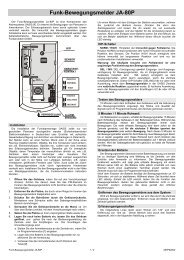
Auf der ausklappbaren Seite 3 finden Sie alle<br />
beschriebenen Bedien elemente und Anschlüsse.<br />
1 Übersicht der Bedienelemente<br />
und Anschlüsse<br />
1.1 Frontseite<br />
1 Eingangsbuchsen für die Kanäle 1 und 2<br />
(XLR/6,3-mm-Klinken-Kombibuchse):<br />
XLR-Anschluss für ein Mikrofon oder<br />
Klinkenanschluss für ein Audiogerät mit Line-<br />
Ausgang (CD-Spieler, Kassettenrecorder etc.)<br />
2 Lautstärkeregler VOLUME für die Kanäle 1 und 2<br />
Bei eingeschaltetem Funkmikrofon leuchtet die<br />
rote LED neben dem zugehörigen Regler:<br />
Kanal 1 für die Empfangsfrequenz 863,05 MHz,<br />
Kanal 2 für 864,80 MHz (nur bei <strong>TXA</strong>-<strong>650</strong>)<br />
3 Klangregler BASS und TREBLE jeweils für die<br />
Kanäle 1 und 2<br />
4 Lautstärkeregler VOLUME 3 für den Kanal 3<br />
5 Eingangsbuchsen (Cinch) für Kanal 3 zum An -<br />
schluss eines Audiogerätes mit Line-Ausgang<br />
6 Eingangsbuchsen (Cinch) für Kanal 4 zum An -<br />
schluss eines Audiogerätes mit Line-Ausgang<br />
Hinweis: Entweder an diese Buchsen ein Gerät<br />
anschließen oder an den 3,5-mm-Klinken -<br />
stecker (11) einen CD-Spieler<br />
7 Lautstärkeregler VOLUME 4 für den Kanal 4<br />
8 Regler MUTE LEVEL zum Einstellen der Laut stärkeabsenkung<br />
der Kanäle 3 und 4 bei Mikrofondurchsagen<br />
9 Anzeige-LEDs<br />
PRIORITY MIC 1+2, grün<br />
leuchtet, wenn die Lautstärke der Kanäle 3 und<br />
4 automatisch bei einer Mikrofondurchsage<br />
abgesenkt wird<br />
AMP ON, gelb<br />
leuchtet bei eingeschaltetem Gerät<br />
All operating elements and connections de -<br />
scribed can be found on the fold-out page 3.<br />
1 Operating Elements and Connections<br />
1.1 Front panel<br />
1 Input jacks for the channels 1 and 2<br />
(combined XLR/6.3 mm jack):<br />
XLR connection for a microphone or<br />
6.3 mm connection for an audio unit with line output<br />
(CD player, tape recorder, etc.)<br />
2 Control VOLUME for the channels 1 and 2<br />
The red LED next to the corresponding control<br />
lights up with the wireless microphone switched<br />
on.<br />
Channel 1 for the receiving frequency 863.05 MHz,<br />
channel 2 for 864.80 MHz (only for <strong>TXA</strong>-<strong>650</strong>)<br />
3 Tone controls BASS and TREBLE, each for the<br />
channels 1 and 2<br />
4 Control VOLUME 3 for channel 3<br />
5 Input jacks (phono) for channel 3 for connection<br />
of an audio unit with line output<br />
6 Input jacks (phono) for channel 4 for connection<br />
of an audio unit with line output<br />
Note: either connect a unit to these jacks or a<br />
CD player to the 3.5 mm plug (11)<br />
7 Control VOLUME 4 for channel 4<br />
8 Control MUTE LEVEL to adjust the volume<br />
attenuation of channels 3 and 4 in case of microphone<br />
announcements<br />
9 Indicating LEDs<br />
PRIORITY MIC 1+2, green<br />
lights up if the volume of channels 3 and 4 is<br />
automatically attenuated in case of a microphone<br />
announcement<br />
AMP ON, yellow<br />
lights up with the unit switched on<br />
LIM, red<br />
lights up if the integrated limiter limits the vo l u me<br />
when reaching the maximum, undistorted level<br />
LIM, rot<br />
leuchtet, wenn der integrierte Limiter die Laut stärke<br />
beim Erreichen des maximalen, unverzerrten<br />
Pegels begrenzt<br />
10 Klangregler BASS und TREBLE gemeinsam für<br />
die Kanäle 3 und 4<br />
1.2 Rückseite<br />
11 3,5-mm-Klinkenstecker zum Anschluss an den<br />
Audioausgang eines tragbaren CD-Spielers<br />
(siehe Kap. 4.3.3); parallel geschaltet mit den<br />
Cinch-Buchsen (6) für Kanal 4<br />
12 Stecker für die Stromversorgung eines tragbaren<br />
CD-Spielers (5 V , Innenkontakt = Pluspol)<br />
13 Mulde zum Einsetzen eines tragbaren CD-Spielers<br />
14 Lüftungsschlitze; nicht abdecken, damit es im<br />
Gerät nicht zu einer Überhitzung kommt!<br />
15 Halterung für die Netzsicherung;<br />
eine durchgebrannte Sicherung nur durch eine<br />
gleichen Typs ersetzen<br />
16 Netzbuchse zum Anschluss an eine Steckdose<br />
(230 V~/50 Hz) über das beiliegende Verbindungskabel<br />
17 Ein-/Ausschalter für das Verstärkerteil<br />
Hinweis: Das Ladeteil ist immer in Betrieb,<br />
sobald das Gerät über die Netzbuchse (16) mit<br />
einer Steckdose verbunden wird.<br />
18 Ladeanzeige für den internen Akkumulator<br />
> 75 %, grün<br />
leuchtet, wenn der Akku über 75 % geladen ist<br />
< 25 %, rot<br />
leuchtet, wenn die Akkuladung unter 25 %<br />
gefallen ist und der Akku geladen werden sollte<br />
CHARGE, Betriebsanzeige für das Ladeteil<br />
rot: der Akku wird geladen<br />
grün: der Ladevorgang ist beendet<br />
19 6,3-mm-Klinkenbuchsen LINE LINK INPUT und<br />
OUTPUT zum Betrieb mehrerer Aktivboxen<br />
(siehe Kap. 4.3.4)<br />
10 Tone controls BASS and TREBLE in common for<br />
channels 3 and 4<br />
1.2 Rear panel<br />
11 3.5 mm plug for connection to the audio output of a<br />
portable CD player (see chapter 4.3.3); con nected<br />
in parallel to the phono jacks (6) for channel 4<br />
12 Plug for the power supply of a portable CD player<br />
(5 V , inside contact = positive pole)<br />
13 Recess for inserting a portable CD player<br />
14 Ventilation slots; do not cover them to prevent<br />
overheating inside the unit!<br />
15 Support for the mains fuse;<br />
only replace a blown fuse by one of the same type<br />
16 Mains jack for connection to a mains socket<br />
(230 V~/50 Hz) via the supplied connection cable<br />
17 POWER switch for the amplifier part<br />
Note: the charging part is always in operation as<br />
soon as the unit is connected via the mains jack<br />
(16) to a mains socket<br />
18 Charging control LED for the internal rechargeable<br />
battery<br />
> 75 %, green<br />
lights up if the rechargeable battery is charged<br />
more than 75 %<br />
< 25 %, red<br />
lights up if the charge of the rechargeable battery<br />
has fallen below 25 % and the rechargable<br />
battery should be charged<br />
CHARGE, power indication for the charging part<br />
red: the rechargeable battery is being charged<br />
green: the charging procedure is terminated<br />
19 6.3 mm jacks LINE LINK INPUT and OUTPUT<br />
for operating several active speaker systems<br />
(see chapter 4.3.4)<br />
20 6.3 mm jack EXT. SPEAKER for parallel operation<br />
of a passive 4 Ω speaker system, e. g. TXB-<strong>600</strong><br />
21 POWER indications<br />
TRANSFER ON AIR, green<br />
without function<br />
20 6,3-mm-Klinkenbuchse EXT. SPEAKER zum<br />
parallelen Betrieb einer passiven 4-Ω-Laut -<br />
sprecherbox, z. B. TXB-<strong>600</strong><br />
21 Betriebsanzeigen<br />
TRANSFER ON AIR, grün<br />
ohne Funktion<br />
LIM, rot<br />
leuchtet, wenn der integrierte Limiter die Laut stärke<br />
beim Erreichen des maximalen, unverzerrten<br />
Pegels begrenzt<br />
POWER AMP ON, gelb<br />
leuchtet bei eingeschaltetem Gerät<br />
2 Hinweise für den sicheren Gebrauch<br />
Das Gerät entspricht allen relevanten Richtlinien der<br />
EU und ist deshalb mit gekennzeichnet.<br />
WARNUNG Das Gerät wird mit lebensgefähr -<br />
licher Netzspannung (230 V~) versorgt.<br />
Nehmen Sie deshalb nie selbst<br />
Eingriffe am Gerät vor. Durch un -<br />
sach ge mäßes Vorgehen besteht die<br />
Gefahr eines elektrischen Schlages.<br />
Beachten Sie auch unbedingt die folgenden Punkte:<br />
● Verwenden Sie das Gerät nur im Innenbereich.<br />
Schützen Sie es vor Tropf- und Spritzwasser,<br />
hoher Luftfeuchtigkeit und Hitze (zulässiger Einsatztemperaturbereich<br />
0 – 40 °C).<br />
● Stellen Sie keine mit Flüssigkeit gefüllten Gefäße,<br />
z. B. Trinkgläser, auf das Gerät.<br />
● Die im Gerät entstehende Wärme muss durch<br />
Luftzirkulation abgegeben wer den. Decken Sie<br />
die Lüftungsöffnungen (14) nicht ab.<br />
● Nehmen Sie das Gerät nicht in Betrieb und ziehen<br />
Sie sofort den Netzstecker aus der Steckdose,<br />
wenn:<br />
1. sichtbare Schäden am Gerät oder am Netz -<br />
kabel vorhanden sind,<br />
2. nach einem Sturz oder Ähnlichem der Verdacht<br />
auf einen Defekt besteht,<br />
LIM, red<br />
lights up if the integrated limiter limits the vol u -<br />
me when reaching the maximum, undistort ed<br />
level<br />
POWER AMP ON, yellow<br />
lights up with the unit switched on<br />
2 Safety Notes<br />
This unit corresponds to all relevant directives of the<br />
EU and is therefore marked with .<br />
WARNING The unit is supplied with hazardous<br />
mains voltage (230 V~). Leave servic -<br />
ing to skilled personnel only. Inexpert<br />
handling or modification of the unit<br />
may cause an electric shock hazard.<br />
It is essential to observe the following items:<br />
● The unit is suitable for indoor use only. Protect it<br />
against dripping water and splash water, high air<br />
humidity, and heat (admissible ambient temperature<br />
range 0 – 40 °C).<br />
● Do not place any vessels filled with liquid, e. g.<br />
drinking glasses, on the unit.<br />
● The heat being generated in the unit has to be<br />
removed via air circulation. Therefore, the air<br />
vents (14) must not be covered.<br />
● Do not set the unit into operation, and immediately<br />
disconnect the mains plug from the mains socket if<br />
1. there is visible damage to the unit or to the<br />
mains cable,<br />
2. a defect might have occurred after a drop or<br />
similar accident,<br />
3. there are malfunctions.<br />
The unit must in any case be repaired by skilled<br />
personnel.<br />
● Never pull the mains cable to disconnect the<br />
mains plug from the mains socket, always seize<br />
the plug!<br />
● For cleaning only use a dry, soft cloth, by no<br />
means chemicals or water.