OM, DMS160, A/AT/Gyro, 2010-01, EN
OM, DMS160, A/AT/Gyro, 2010-01, EN
OM, DMS160, A/AT/Gyro, 2010-01, EN

Create successful ePaper yourself
Turn your PDF publications into a flip-book with our unique Google optimized e-Paper software.
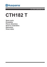
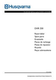
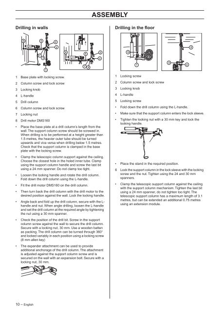
Drilling in walls<br />
6 5<br />
1 Base plate with locking screw.<br />
2 Column screw and lock screw<br />
3 Locking knob<br />
4 L-handle<br />
5 Drill column<br />
6 Column screw and lock screw<br />
7 Locking nut<br />
8 Drill motor <strong>DMS160</strong><br />
• Place the base plate at a drill column’s length from the<br />
wall. The support column screw should be screwed in.<br />
When drilling is to be performed at a height greater than<br />
1.5 metres, the heavier outer tube should be turned<br />
upwards and vice versa when drilling below 1.5 metres.<br />
Check that the support column is clamped in the base<br />
plate with the locking screw.<br />
• Clamp the telescopic column support against the ceiling.<br />
Choose the closest hole in the holed inner tube. Clamp<br />
using the support column handle and screw the last bit<br />
using a 24 mm spanner. Do not clamp too tight.<br />
• Loosen the locking handle and rotate the drill column.<br />
Fold down the drill column using the L-handle.<br />
• Fit the drill motor <strong>DMS160</strong> on the drill column.<br />
• Then turn back the drill column with the drill motor to the<br />
desired position against the wall. Lock the locking handle.<br />
• Angle back and fold up the drill column, secure with the Lhandle<br />
and nut. When angle drilling, loosen the L-handle<br />
and set the drill column at the required angle by tightening<br />
the nut using a 30 mm spanner.<br />
• Check the position of the drill bit. Screw in the support<br />
column screw against the wall to secure the drill column.<br />
Secure with a locking nut, 30 mm. Use a wooden batten<br />
as packing. The drill column can be turned through 360°<br />
and locked variably in each position using a locking screw<br />
(8 mm allen key)<br />
• The expander attachment can be used to provide<br />
additional anchorage of the drill column. The attachment<br />
is adjusted against the support column screw and is<br />
secured on the wall with an expansion bolt. Secure with a<br />
locking nut, 30 mm.<br />
10 – English<br />
7 4<br />
1<br />
2<br />
3<br />
6<br />
5<br />
7 4<br />
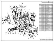
ASSEMBLY<br />
2<br />
3<br />
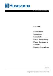
Drilling in the floor<br />
1 Locking screw<br />
2 Column screw and lock screw<br />
3 Locking knob<br />
4 L-handle<br />
5 Locking screw<br />
• Fold down the drill column using the L-handle.<br />
• Make sure that the support column enters the lock sleeve.<br />
• Tighten the locking nut with a 30 mm key and lock the<br />
locking handle.<br />
• Place the stand in the required position.<br />
6 Lock the support column in the lock sleeve with the locking<br />
screw and the nut. Tighten using the 24 and 30 mm<br />
spanners.<br />
• Clamp the telescopic support column against the ceiling<br />
with the support column mechanism. Tighten the last bit<br />
using a 24 mm spanner, do not tighten too tight. The<br />
telescopic support column has a maximum length of 3.1<br />
metres, but can be extended an additional 0.75 metres<br />
using an extension module.