
You also want an ePaper? Increase the reach of your titles
YUMPU automatically turns print PDFs into web optimized ePapers that Google loves.
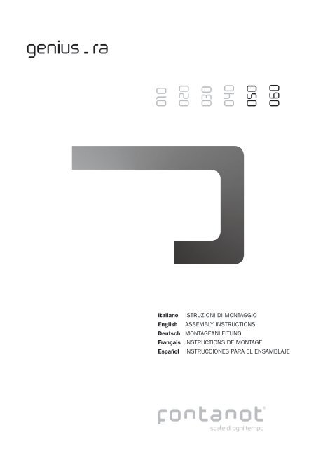
<strong>genius</strong> - <strong>ra</strong><br />
010<br />
020<br />
030<br />
040<br />
050<br />
060<br />
Italiano ISTRUZIONI DI MONTAGGIO<br />
English ASSEMBLY INSTRUCTIONS<br />
Deutsch MONTAGEANLEITUNG<br />
F<strong>ra</strong>nçais INSTRUCTIONS DE MONTAGE<br />
Español INSTRUCCIONES PARA EL ENSAMBLAJE
ATTENZIONE: per un corretto ser<strong>ra</strong>ggio dei g<strong>ra</strong>ni 001010 - 001013, ruotare la chiave di circa 180° dal punto di contatto.<br />
Una ulteriore inutile rotazione potrebbe danneggiare il g<strong>ra</strong>dino.<br />
ATTENTION: for the correct fixing of 001010 - 001013, turn the key around 180° from the contact point. A further additional<br />
rotation could damage the tread.<br />
ACHTUNG: zur korrekten Befestigung der Stifte 001010 - 001013 den Schlüssel um c.a. 180° gegenüber dem<br />
Befestigungspunkt drehen. Das weitere, unnötige Anziehen kann zur Beschädigung der Stufe führen.<br />
ATTENTION: pour serrer correctement les vis 001010 - 001013, tourner le clef à environ 180° à partir du point de contact.<br />
Un ultérieur et inutile ser<strong>ra</strong>ge pour<strong>ra</strong>it endommager la marche.<br />
ATENCIÓN: pa<strong>ra</strong> apretar correctamente los tornillos 001010 - 001013 es suficiente apretar la llave 180° desde el punto de<br />
contacto. Apretar más de lo indicado es inútil y puede dañar los peldaños.
3 - Genius 050 - 060 RA
Italiano<br />
Prima di iniziare l’assemblaggio, sballare tutti gli elementi della scala. Sistemarli su una superficie ampia e<br />
verificare la quantità degli elementi utilizzando la distinta pezzi allegata.<br />
Assemblaggio<br />
1. Misu<strong>ra</strong>re attentamente l’altezza da pavimento a pavimento (H) (fig. 2).<br />
2. Misu<strong>ra</strong>re attentamente il foro solaio (F) (fig. 2).<br />
3. Calcolare il valore della pedata (P):<br />
per le versioni con larghezza g<strong>ra</strong>dino L = 67 / 74 cm e pedata 19÷22,5 cm:<br />
a) Sott<strong>ra</strong>rre al valore trovato del foro solaio (F) le seguenti dimensioni:<br />
1) g<strong>ra</strong>dino finale, scegliere una delle due misure possibili, 29 e 26,5 cm;<br />
2) g<strong>ra</strong>dini d’angolo;<br />
3) distanza dal muro, da 3 a 6 cm.<br />
b) Dividere questo valore per il numero dei g<strong>ra</strong>dini rimanenti.<br />
Esempio: per un foro solaio di 228 cm e una scala con g<strong>ra</strong>dino L=74:<br />
228 – 29 – 68 – 3 / 6 = 21.33 cm (fig. 5).<br />
per le versioni con larghezza g<strong>ra</strong>dino L =74 / 81 / 88 / 95 cm e pedata 22,5÷26 cm:<br />
a) Sott<strong>ra</strong>rre al valore trovato del foro solaio (F) le seguenti dimensioni:<br />
1) g<strong>ra</strong>dino finale, scegliere una delle tre misure possibili, 32, 29, e 26,5 cm;<br />
2) g<strong>ra</strong>dini d’angolo o pianerottolo;<br />
3) distanza dal muro, da 3 a 6 cm.<br />
b) Dividere questo valore per il numero g<strong>ra</strong>dini rimanenti.<br />
Esempio: per un foro solaio di 324 cm e una scala con g<strong>ra</strong>dino L=88:<br />
324 – 29 – 82 – 5 / 8 = 26 cm (fig. 6).<br />
4. Calcolare il valore dell’alzata medio:<br />
1) Sott<strong>ra</strong>rre 20 cm (altezza della prima alzata) al valore dell’altezza da pavimento a pavimento (H)<br />
precedentemente rilevato;<br />
2) Dividere questo valore per il numero delle alzate meno una. Il valore trovato dovrà essere un numero<br />
compreso f<strong>ra</strong> 18 e 23 cm.<br />
Esempio: per un’altezza misu<strong>ra</strong>ta da pavimento a pavimento di 275,5 cm e una scala di 14 alzate;<br />
(275,5 – 20 / (14 – 1) ) = 19,65 cm (fig. 2).<br />
5. Determinare la quantità degli spessori 031078.<br />
a) Per determinare la quantità totale degli spessori 031078, in funzione del numero di alzate della scala e<br />
dell’altezza da pavimento a pavimento (H), utilizzare la TAB. 2 (H = altezza, A = alzata).<br />
Esempio: per un’altezza misu<strong>ra</strong>ta da pavimento a pavimento di 275,5 cm e una scala di 14 alzate. In<br />
corrispondenza di 276, nella fila A=14, si legge 41.<br />
La struttu<strong>ra</strong> della scala è composta da tre diverse tipologie di supporti:<br />
1) supporto finale 116012 e 116022 per il fissaggio della scala sul solaio di arrivo in alto;<br />
2) supporto intermedio 116002 e 116004 aventi rispettivamente due differenti misure di pedata, 19÷22,5<br />
cm e 22,5÷26 cm, secondo la configu<strong>ra</strong>zione scelta.<br />
Attenzione: per le versioni con larghezza g<strong>ra</strong>dino L = 74 e 81 cm, e pedata del g<strong>ra</strong>dino rettilineo pari a<br />
22,5÷26 cm, in corrispondenza dei g<strong>ra</strong>dini d’angolo, gli intermedi sono pedata 19÷22,5 cm;<br />
3) supporto di base 116006 per il fissaggio della scala a pavimento (fig. 1).<br />
Distribuire gli spessori 031078, in successione, partendo dal supporto di base 116006, sulla parte<br />
predisposta dei supporti, fino al loro esaurimento.<br />
b) Per calcolare la quantità degli spessori, nel caso in cui il numero delle alzate previsto non sia presente<br />
nella TAB. 2:<br />
calcolare il valore dell’alzata medio;<br />
sott<strong>ra</strong>rre 18 cm (altezza alzata minima) al valore dell’alzata medio;<br />
moltiplicare questo valore per il numero delle alzate meno due;<br />
dividere il risultato per 0,5.<br />
Esempio: per un’altezza misu<strong>ra</strong>ta da pavimento a pavimento di 275,5 cm e una scala di 14 alzate il valore<br />
medio dell’alzata risulta di:<br />
(276 - 20/ 14 - 1) = 19,69 cm (Il valore trovato dovrà essere un numero compreso f<strong>ra</strong> 18 e 23 cm).<br />
(19,69 - 18) x (14 - 2) / 0.5 = 40,32 = 41.<br />
Distribuire gli spessori 031078, in successione, partendo dal supporto di base 116006, sulla parte<br />
predisposta dei supporti, fino al loro esaurimento.<br />
6. Determinare la quantità delle colonnine finali, intermedie e di giunzione (fig. 1) (fig. 8).<br />
Attenzione: conside<strong>ra</strong>re che la lunghezza dei tondini forniti copre al massimo la ringhie<strong>ra</strong> di tre g<strong>ra</strong>dini. Di<br />
4 - Genius 050 - 060 RA
conseguenza si dovrà inserire una colonnina di giunzione (z) al massimo ogni tre g<strong>ra</strong>dini.<br />
a) Assemblaggio delle colonnine finali (x): inserire l’articolo 011071 nel foro della colonnina 127031 o<br />
127035 dal lato della svasatu<strong>ra</strong>. Dall’altro lato inserire l’articolo 033159 e poi l’articolo 031096 e avvitare.<br />
Assemblare l’elemento 033158 nelle colonnine 127031 o 127035 con il foro dal lato della svasatu<strong>ra</strong> e<br />
ser<strong>ra</strong>re definitivamente (all’interno del particolare 033158 sono già presenti gli articoli 001027 e 001028<br />
<strong>ra</strong>ppresentati in fig. 1).<br />
Inserire l’elemento 033078 nell’elemento 033158. Avvitare con l’elemento 011072.<br />
b) Assemblaggio delle colonnine intermedie (y): avvitare l’articolo 001011 nello 034040 senza ser<strong>ra</strong>re.<br />
Inserire l’articolo 011070 nel foro della colonnina 127031 o 127035 dal lato della svasatu<strong>ra</strong> e avvitarlo agli<br />
articoli 001011+034040.<br />
Assemblare l’elemento 033158 nelle colonnine 127031 o 127035 con il foro dal lato della svasatu<strong>ra</strong> e<br />
ser<strong>ra</strong>re definitivamente (all’interno del particolare 033158 sono già presenti gli articoli 001027 e 001028<br />
<strong>ra</strong>ppresentati in fig. 1).<br />
Inserire l’elemento 033078 nell’elemento 033158. Avvitare con l’elemento 011072.<br />
c) Assemblaggio delle colonnine di giunzione tondini (z): inserire l’articolo 011071 nel foro della colonnina<br />
127031 o 127035 dal lato della svasatu<strong>ra</strong>. Dall’altro lato inserire l’articolo 033159, sov<strong>ra</strong>pporvi l’articolo<br />
033160 e avvitare.<br />
Assemblare l’elemento 033158 nelle colonnine 127031 o 127035 con il foro dal lato della svasatu<strong>ra</strong> e<br />
ser<strong>ra</strong>re definitivamente (all’interno del particolare 033158 sono già presenti gli articoli 001027 e 001028<br />
<strong>ra</strong>ppresentati in fig. 1).<br />
Inserire l’elemento 033078 nell’elemento 033158. Avvitare con l’elemento 011072.<br />
7. Assemblare gli elementi 116022, 116012 e 033150 del supporto finale con gli articoli 011062, 009008 e<br />
005009, secondo la profondità scelta in precedenza (vedi punto 3) (fig. 3 - 5 - 6).<br />
In base alla profondità della pedata, inserire gli articoli 033150 secondo i seguenti criteri:<br />
a. pedata 32 cm: utilizzare gli articoli 033150 senza nessuna modifica;<br />
b. pedata 29 cm: tagliare lungo la linea di pretaglio;<br />
c. pedata 26,5 cm: non utilizzare gli articoli 033150.<br />
8. Tagliare, se necessario, il g<strong>ra</strong>dino rettilineo finale con il seghetto alternativo (il taglio è necessario per le<br />
profondità pari a 29 e 26,5 cm (fig. 3). Eliminare con carta a vetro eventuali imperfezioni presenti sul bordo e<br />
proteggere con la tinta da legno fornita.<br />
9. Fo<strong>ra</strong>re con punta Ø 5 mm su ent<strong>ra</strong>mbi i lati i g<strong>ra</strong>dini ad una distanza pari alla pedata calcolata<br />
precedentemente (vedi punto 3) (fig. 8A).<br />
Attenzione: fo<strong>ra</strong>re il g<strong>ra</strong>dino finale solo sul lato dove è prevista la ringhie<strong>ra</strong>!<br />
Inserire l’articolo 001004 negli articoli 033142 e assemblarli quindi sui g<strong>ra</strong>dini rettilinei con le viti 002040<br />
ad una distanza pari alla pedata calcolata precedentemente (vedi punto 3) (fig. 8A).<br />
10.Inserire gli articoli 001010 nei g<strong>ra</strong>dini (fig. 1). Determinare la posizione del g<strong>ra</strong>dino finale rispetto al supporto<br />
116012. Riportare il posizionamento rilevato in corrispondenza del foro solaio.<br />
11.Determinare il punto di fo<strong>ra</strong>tu<strong>ra</strong> sul solaio in corrispondenza delle asole presenti sulla piast<strong>ra</strong> del supporto<br />
116022. Fo<strong>ra</strong>re con punta Ø 18 mm (fig. 3).<br />
12.Fissare il supporto finale al solaio con gli articoli 008020 senza ser<strong>ra</strong>re. Assemblare il g<strong>ra</strong>dino finale<br />
al supporto con gli articoli 009012 e 011038 e ser<strong>ra</strong>re. Verificare l’orizzontalità del g<strong>ra</strong>dino e ser<strong>ra</strong>re<br />
definitivamente gli articoli 008020 (fig. 4).<br />
13.Applicare l’articolo 132013 per coprire la piast<strong>ra</strong> (fig. 4) utilizzando gli elementi 008004+002035.<br />
14.Accostare il supporto intermedio 116002 o 116004 sul supporto finale 116012 interponendo i relativi<br />
spessori 031078 calcolati precedentemente e bloccarlo con una pinza autobloccante. Inserire il bullone<br />
003009, gli elementi 009041, 023039, 009040 e 005040. Assemblare il g<strong>ra</strong>dino con gli articoli 009012 e<br />
011038 senza ser<strong>ra</strong>re; t<strong>ra</strong> un g<strong>ra</strong>dino e l’altro inserire da un lato una colonnina 127031 o 127035 (finale x,<br />
intermedia y o di giunzione z) (fig. 8) della ringhie<strong>ra</strong>, e dall’altro lato una colonnina provvisoria 127033 (alte<br />
135 cm, senza fori) per determinare l’esatto allineamento dell’insieme. Sostituire la colonnina provvisoria<br />
con una porzione della stessa precedentemente tagliata in base alla misu<strong>ra</strong> dell’alzata. Se necessario,<br />
tagliare le colonnine 127031 o 127035 dalla parte inferiore per ottenere un’altezza della ringhie<strong>ra</strong> pari a<br />
circa 100 cm. Orientare le colonnine con l’elemento 033078 con la parte fo<strong>ra</strong>ta verso l’alto (fig. 7). Verificare<br />
l’orizzontalità del g<strong>ra</strong>dino e la verticalità delle colonnine, ser<strong>ra</strong>re definitivamente il dado 005040, con una<br />
coppia pari a 100 Nm, e gli articoli 009012 e 011038. Puntellare i supporti a mano a mano che si procede<br />
con l’assemblaggio della struttu<strong>ra</strong> e dei g<strong>ra</strong>dini, per far sì che il peso non g<strong>ra</strong>vi sul solaio.<br />
Assemblaggio dei g<strong>ra</strong>dini d’angolo: utilizzare una colonnina provvisoria anche sul lato esterno per<br />
determinare il posizionamento di fulcro dei g<strong>ra</strong>dini d’angolo (si consiglia l’uso della colonnina provvisoria al<br />
fine di evitare danneggiamenti della colonnina definitiva).<br />
E’ indispensabile inserire un puntello ogni 4/5 supporti ed è seve<strong>ra</strong>mente vietato, per motivi di sicurezza,<br />
salire sulla scala prima di averla fissata a pavimento e irrigidita. Proseguire così con l’assemblaggio dei<br />
restanti supporti intermedi (fig. 1).<br />
5 - Genius 050 - 060 RA
15.Assemblare infine il supporto di base 116006, completo di g<strong>ra</strong>dino, interponendo gli spessori 031078<br />
calcolati precedentemente. Ser<strong>ra</strong>re definitivamente l’articolo 003039 (fig. 1). Smontare il primo ed il<br />
secondo g<strong>ra</strong>dino, controllare la posizione della scala rispetto al vano ed eventualmente correggerla. Fo<strong>ra</strong>re il<br />
pavimento con punta Ø 14 mm; inserire gli articoli 008021 e ser<strong>ra</strong>re definitivamente. Rimontare i g<strong>ra</strong>dini tolti<br />
precedentemente (fig. 1). Terminato il montaggio, determinare l’altezza della colonnina di fulcro e sostituire la<br />
colonnina provvisoria con una colonnina 127033 o 127045 tagliata a misu<strong>ra</strong> (fig. 8B).<br />
Assemblaggio struttu<strong>ra</strong> pianerottolo (passare al punto 17 per i modelli senza pianerottolo)<br />
16.Assemblare il supporto 116010 al supporto intermedio 116002 interponendo gli spessori 031078 calcolati<br />
precedentemente senza ser<strong>ra</strong>re definitivamente. Assemblare gli elementi 116024 alla struttu<strong>ra</strong> pianerottolo<br />
116020 / 116018 / 116016 / 116014 nella posizione (sono possibili tre misure) data dalla distanza<br />
dal muro. Assemblare la struttu<strong>ra</strong> pianerottolo al supporto 116010, sostenere la struttu<strong>ra</strong> con un numero<br />
di puntelli sufficiente, con gli articoli 116026 e 011065. Assemblare l’articolo 116008 alla struttu<strong>ra</strong><br />
pianerottolo con gli articoli 116026 e 011065.<br />
Posizionare il pianerottolo di legno, senza fissarlo, e verificare l’orizzontalità e l’allineamento della scala.<br />
Assemblare il supporto intermedio 116002 interponendo gli spessori 031078 calcolati precedentemente, e<br />
successivamente il g<strong>ra</strong>dino rettilineo utilizzando i paletti per ga<strong>ra</strong>ntire l’allineamento della struttu<strong>ra</strong>. Ser<strong>ra</strong>re<br />
definitivamente gli articoli 003039 con una coppia di ser<strong>ra</strong>ggio pari a 100Nm. Togliere il pianerottolo e<br />
assemblare gli articoli 047083, rispettando il piano di appoggio superiore, con gli articoli 011057, fo<strong>ra</strong>re<br />
la struttu<strong>ra</strong> con punta Ø 5 mm e filettare M 6. T<strong>ra</strong>cciare il centro dei fori in corrispondenza delle piastre<br />
116024, fo<strong>ra</strong>re il muro con punta Ø 18 mm e creare nel foro una sede iniziale Ø 19 mm profonda 15 mm per<br />
il dado 006001 di ser<strong>ra</strong>ggio. Assemblare gli articoli 006001 sui ti<strong>ra</strong>nti 046029 senza arrivare a fondo corsa;<br />
fissare a muro con la resina chimica (non fornita), attendere l’essiccazione, e ser<strong>ra</strong>re definitivamente gli<br />
articoli 006001; coprire con i tappi 031083/031021/031044. Posizionare il pianerottolo di legno e fissare<br />
con le viti 002040. Proseguire con l’assemblaggio dei restanti supporti intermedi (fig. 9).<br />
Assemblaggio dei fissaggi a muro e a pavimento<br />
17.Fissare a muro la scala utilizzando gli elementi 033010 con gli articoli 008004, 011053, 031059, 033056,<br />
011057 e 005035 (fo<strong>ra</strong>re con punta Ø 8 mm) (fig. 9).<br />
18.Irrigidire ulteriormente la scala nei seguenti punti:<br />
1. Inserire in una posizione intermedia (6°-7° alzata) il palo telescopico 047087- 047085 a pavimento con<br />
gli articoli 047089 e 031070; tagliare se necessario in altezza; la base 047087 ed il finale 047085 devono<br />
avere una lunghezza equivalente; conside<strong>ra</strong>re almeno 25 cm di inserimento del finale 047085 nella base<br />
047087. Fo<strong>ra</strong>re con punta Ø 13 mm il supporto e fissare la staffa del sostegno 047089 con gli articoli<br />
011062, 009008 e 005009. Fo<strong>ra</strong>re (due fori) con punta Ø 9 mm gli elementi 047085 e 047087, fissare<br />
la base con del silicone e assemblare l’articolo di bloccaggio 046046 e 004052. Incollare con silicone gli<br />
articoli 031083 o 031021 o 031044 in corrispondenza dei fori della piast<strong>ra</strong> a pavimento. In caso di altezze<br />
superiori ai 160 cm, fo<strong>ra</strong>re il pavimento con punta Ø 18 mm e fissare con gli articoli 046029, 006001,<br />
031083 o 031021 o 031044.<br />
2. Fissare a muro la scala utilizzando il palo telescopico 047087, 047085 con gli articoli 046029 e 006001;<br />
fo<strong>ra</strong>re il muro con punta Ø 18 mm; creare nel foro una sede iniziale Ø 19 mm profonda 15 mm per il dado<br />
006001 di ser<strong>ra</strong>ggio.<br />
Assemblare gli articoli 006001 sui ti<strong>ra</strong>nti 046029 senza arrivare a fondo corsa; fissare a muro con la resina<br />
chimica, attendere l’essiccazione, e ser<strong>ra</strong>re definitivamente gli articoli 006001. Fo<strong>ra</strong>re con punta Ø 13 mm il<br />
supporto e fissare la staffa del sostegno 047089 con gli articoli 011062, 009008 e 005009.<br />
Assemblaggio della ringhie<strong>ra</strong><br />
19.Tagliare a misu<strong>ra</strong> i segmenti di corrimano 140053; applicare i tappi terminali 033164 alle estremità del<br />
corrimano con gli articoli 011069 e 004034, fo<strong>ra</strong>re con punta Ø 6 mm (fig. 7). Unire i segmenti di corrimano<br />
con l’articolo 046011 interponendo l’articolo 031076. Per ottenere un ottimo fissaggio, il corrimano deve<br />
compiere circa 1/8 di giro dal punto di contatto.<br />
20.Fissare il corrimano alle colonnine, con gli articoli 002031; mantenere le colonnine verticali. In caso di<br />
ringhie<strong>ra</strong> esterna e di balaust<strong>ra</strong> al piano superiore, inserire gli articoli a gomito 033162, 033163 e 033164<br />
con le viti 012014 e 001017 per i cambi di direzione.<br />
21.Dopo aver montato il corrimano, ser<strong>ra</strong>re le viti 001004 e 001010.<br />
22.Determinare la posizione sul g<strong>ra</strong>dino della colonnina in prossimità del fulcro della scala dal lato interno.<br />
Tagliare le colonnine del fianco interno della ringhie<strong>ra</strong> in modo che il corrimano non interferisca con i fissaggi<br />
della colonnina di fulcro.<br />
23.Tagliare a misu<strong>ra</strong> i segmenti di corrimano 140053; assemblarli con l’articolo 046011 interponendo l’articolo<br />
6 - Genius 050 - 060 RA
031076. Per ottenere un ottimo fissaggio, il corrimano deve compiere circa 1/8 di giro dal punto di contatto.<br />
24.Applicare i tappi terminali 033164 ad una estremità del corrimano con gli articoli 011069 e 004034, fo<strong>ra</strong>re<br />
con punta Ø 6 mm (fig. 7). Applicare gli articoli 033057, 033127, 033164, 005035, 011057 e 002033<br />
sull’alt<strong>ra</strong> estremità del corrimano. Fissare il corrimano con gli articolo 002031. Determinare l’altezza della<br />
colonnina in prossimità del fulcro e posizionarla verificandone la verticalità.<br />
25.In caso di ringhie<strong>ra</strong> esterna, adeguare l’altezza delle colonnine in modo tale che l’inclinazione del corrimano<br />
sia uguale a quella della ringhie<strong>ra</strong> interna. Fissare la ringhie<strong>ra</strong> esterna al muro in corrispondenza dell’ultima<br />
colonnina (più vicina al muro) (punto 17). In caso di ringhie<strong>ra</strong> esterna e di balaust<strong>ra</strong> al piano superiore,<br />
inserire gli articoli a gomito 033162, 033163 e 033164 con le viti 012014 e 001017 per i cambi di<br />
direzione.<br />
26.Determinare la lunghezza dei tondini 076058 in base al calcolo fatto precedentemente (punto 14) e alla<br />
configu<strong>ra</strong>zione della scala e tagliarli. Assemblare i tondini 076058. Per agevolare l’inserimento dei tondini<br />
in corrispondenza delle colonnine di giunzione, smontare gli articoli 033159 e 033160. Infine ser<strong>ra</strong>re gli<br />
elementi 001011 precedentemente inseriti negli articoli 034040 delle colonnine intermedie.<br />
27.Completare l’assemblaggio della ringhie<strong>ra</strong>, inserendo gli elementi 004051 nella parte late<strong>ra</strong>le dei g<strong>ra</strong>dini e<br />
gli elementi 031064 nella parte inferiore delle colonnine 127031 o 127035 (fig. 1).<br />
28.Inserire gli articoli 031063 negli elementi 031062 e coprire tutti i supporti. Tagliare l’articolo 031062 in<br />
corrispondenza del supporto di base 116006.<br />
29.Applicare l’etichetta adesiva sul primo g<strong>ra</strong>dino, lato ringhie<strong>ra</strong>.<br />
7 - Genius 050 - 060 RA
English<br />
Unpack each element before starting to assemble the staircase. Position the elements on an ample surface and<br />
check the number of parts against the attached parts list.<br />
Assembly<br />
1. Carefully measure the height from floor to floor (H) (Fig.2).<br />
2. Carefully measure the floor opening (F) (Fig. 2).<br />
3. Calculate the value of the going (P):<br />
for the versions with a tread width (L) of 67 - 74 cm and a step of 19-22.5 cm:<br />
a) Subt<strong>ra</strong>ct the following dimensions from the floor opening (F) value obtained:<br />
1) final tread, select one of the two possible measurements: 29 and 26.5 cm;<br />
2) corner treads;<br />
3) distance from the wall 3 to 6 cm.<br />
b) Divide this value by the remaining number of treads.<br />
Example: for a floor opening of 228 cm and a staircase with a tread width (L) of 74 cm:<br />
228 - 29 - 68 - 3 / 6 = 21.33 cm.<br />
for the versions with a tread width (L) of 74 / 81 / 88 / 95 cm and a step of 22.5-26 cm:<br />
a) Subt<strong>ra</strong>ct the following dimensions from the floor opening (F) value obtained:<br />
1) final tread, select one of the three possible measurements, 32, 29, and 26.5 cm;<br />
2) corner or landing treads;<br />
3) distance from the wall 3 to 6 cm.<br />
b) Divide this value by the remaining number of treads.<br />
Example: For a floor opening of 324 cm and a staircase with a tread width (L) of 88 cm:<br />
324 – 29 – 82 – 5 / 8 = 26 cm.<br />
4. Calculate the value of the ave<strong>ra</strong>ge rise:<br />
a) Subt<strong>ra</strong>ct 20 cm (height of first rise) from the floor to floor height (H) previously measured.<br />
b) Divide this value by the number of rises less one.<br />
The value obtained must be a number between 18 and 23 cm.<br />
Example: for a measured height of 275.5 cm from floor to floor and a staircase with 14 rises;<br />
(275.5 - 20 / (14 - 1) ) = 19.65 cm (Fig. 2)<br />
5. Determine the number of plastic spacers 031078.<br />
a) To determine the total number of spacers 031078 in relation to the number of staircase rises and the<br />
height from floor to floor (H), refer to Table 2 (H = height, A = rise).<br />
Example: for a measured height of 275.5 cm from floor to floor and a staircase with 14 rises.<br />
In correspondence to 276, in the row A=14 the number of plastic spacers given is 41.<br />
The staircase structure is composed of three different types of support:<br />
1) end support 116012 and 116022 to fasten the staircase to the top landing floor<br />
2) intermediate support 116002 and 116004, respectively with two different step measurements, 19-22.5<br />
cm and 22.5-26 cm, depending on the configu<strong>ra</strong>tion chosen.<br />
Warning: for the versions with a tread width (L) of 74 and 81 cm and a st<strong>ra</strong>ight tread step of 22.5-26 cm, the<br />
intermediate supports have a step of 19-22.5 cm in correspondence to the corner treads.<br />
3) base support 116006 for fastening the staircase to the floor (Fig. 1).<br />
Distribute the plastic spacers 031078 in sequence starting from the base support 116006, where provision<br />
has been made on the supports, until they have all been used up.<br />
b) To calculate the number of plastic spacers if the required number of rises is not indicated in Table 2:<br />
calculate the value of the ave<strong>ra</strong>ge rise;<br />
subt<strong>ra</strong>ct 18 cm (minimum rise height) from the ave<strong>ra</strong>ge rise value;<br />
multiply this value by the number of rises less two;<br />
divide the result by 0.5.<br />
Example: for a measured height of 275.5 cm from floor to floor and a staircase with 14 rises, the ave<strong>ra</strong>ge<br />
value of the rise is:<br />
(276 - 20/ 14 - 1) = 19.69 cm (the value obtained must be a number between 18 and 23 cm).<br />
(19.69 – 18) x (14 - 2) / 0.5 = 40.32 = 41.<br />
Distribute the plastic spacers 031078 in sequence starting from the base support 116006, where provision<br />
has been made on the supports, until they have all been used up.<br />
6. Determine the number of end, intermediate and joining balusters (Fig. 1) (Fig. 8).<br />
Warning: take into account that the length of the rods provided cover the <strong>ra</strong>iling over a maximum of three<br />
treads. Consequently, a joining baluster (z) should be fitted every three treads.<br />
a) End baluster assembly (x): fit the part 011071 in the hole of the baluster 127031 or 127035 on the<br />
countersink side. From the other side fit the part 033159 and then the part 031096 and screw on.<br />
Fit the part 033158 into the balusters 127031 or 127035 with the hole on the countersink side and finally<br />
tighten them (the parts 001027 and 001028 are already fitted in the part 033158 as shown in Fig. 1).<br />
Fit the part 033078 into the part 033158. Screw on with the part 011072.<br />
8 - Genius 050 - 060 RA
) Intermediate baluster assembly (y): Screw the part 001011 into the part 034040 without tightening. Fit<br />
the part 011070 in the hole of the baluster 127031 or 127035 from the countersink side and screw it onto<br />
the parts 001011+034040.<br />
Fit the part 033158 into the balusters 127031 or 127035 with the hole on the countersink side and finally<br />
tighten them (the parts 001027 and 001028 are already fitted in the part 033158 as shown in Fig. 1).<br />
Fit the part 033078 in the part 033158. Screw on with the part 011072.<br />
c) Rod joining baluster assembly (z): fit the part 011071 in the hole of the baluster 127031 or 127035 on<br />
the countersink side. On the other side fit the part 033159, overlay the part 033160 and screw it on. Fit the<br />
part 033158 into the balusters 127031 or 127035 with the hole on the countersink side and finally tighten<br />
them (the parts 001027 and 001028 are already fitted in the part 033158 as shown in Fig. 1).<br />
Fit the part 033078 in the part 033158. Screw on with the part 011072.<br />
7. Assemble the parts 116022, 116012 and 033150 of the end support with the parts 011062, 009008 and<br />
005009 according to the depth chosen previously. (see point 3) (Fig. 3 - 5 - 6).<br />
Based on the step depth, fit the parts 033150 according to the following criteria:<br />
a) 32 cm step: use the parts 033150 without any modification;<br />
b) 29 cm step: cut along the pre-cut line;<br />
c) 26.5 cm step: do not use the parts 033150.<br />
8. Cut, if necessary, the st<strong>ra</strong>ight final tread with the muley saw (cutting is required for the depths of 29 and<br />
26.5 cm (Fig. 3). Sand off any imperfections on the edge using sandpaper and protect with the wood stain<br />
provided.<br />
9. Using a 5 mm Ø bit, drill a hole in the treads on either side at a distance equal to the step calculated<br />
previously<br />
(see point 3) (Fig. 8A).<br />
Warning: drill a hole in the final tread only on the side where the <strong>ra</strong>iling will be fitted!<br />
Fit the part 001004 in the parts 033142 and then assemble them on the st<strong>ra</strong>ight treads using the screws<br />
002040 at a distance equal to the step calculated previously (see point 3) (Fig. 8A).<br />
10.Fit the parts 001010 on the treads (Fig. 1). Determine the position of the final tread with respect to the<br />
support 116012 and position it in correspondence to the floor opening according to the measurement made.<br />
11.Determine the opening point in the floor in correspondence to the slot in the support plate 116022. Drill a<br />
hole using an 18 mm Ø bit (Fig. 3).<br />
12.Fasten the end support to the floor using the parts 008020 without tightening. Assemble the final tread to<br />
the support with the parts 009012 and 011038 and tighten. Check that the tread is horizontal and finally<br />
secure the parts 008020 (Fig. 4).<br />
13.Fit the part 132013 to cover the plate (Fig. 4) using the parts 008004+002035.<br />
14.Place the intermediate support 116002 or 116004 on the end support 116012 interposing the relative<br />
plastic spacers 031078 calculated previously and lock it with a self-locking clamp. Fit the bolt 003009, the<br />
parts 009041, 023039, 009040 and 005040. Assemble the tread with the parts 009012 and 011038<br />
without tightening; on one side between two treads fit a <strong>ra</strong>iling baluster 127031 or 127035 (end x,<br />
intermediate y or joining z) (Fig. 8), and on the other side a provisional baluster 127033 (135 cm high without<br />
holes) to determine the exact alignment of the assembly. Replace the provisional baluster with a section of<br />
the same baluster previously cut based on the rise measurement. If necessary, cut the balusters 127031 or<br />
127035 on the lower side to obtain a <strong>ra</strong>iling height of about 100 cm. Orient the the balusters with the part<br />
033078 with the drilled part facing up (Fig. 7). Check that the tread is horizontal and the balusters vertical,<br />
finally tighten the nut 005040 to a torque of 100 Nm, and the parts 009012 and 011038. Prop up the<br />
supports as you proceed with assembly of the structure and the treads to ensure that the weight is not borne<br />
by the floor.<br />
Corner tread assembly: use a provisional baluster also on the outside to determine positioning of the corner<br />
tread fulcrum (it is recommended to use the provisional baluster to prevent damaging the end baluster).<br />
It is essential to fit a prop every 4-5 supports and, for safety reasons, it is strictly prohibited to climb the<br />
staircase before having fastened it to the floor and stiffened it. Continue in the same way with assembly of<br />
the remaining intermediate supports (Fig. 1).<br />
15.Finally, assemble the base support 116006, complete with tread, interposing the plastic spacers 031078<br />
calculated previously. Finally tighten the part 003039 (Fig. 1). Remove the first and the second tread and<br />
check the position of the staircase with respect to the stairwell opening and correct it if necessary. Drill a<br />
hole in the floor using a 14 mm Ø bit: fit the parts 008021 and finally tighten them. Refit the treads removed<br />
previously (Fig. 1). When assembly has been completed, determine the height of the fulcrum baluster and<br />
replace the provisional baluster with a baluster 127033 or 127045 cut to size (Fig. 8B).<br />
Landing structure assembly (go to point 17 for models without landing)<br />
16.Assemble the support 116010 to the intermediate support 116002 interposing the plastic spacers<br />
031078 calculated previously without tightening. Assemble the parts 116024 to the landing structure<br />
116020/116018/116016/116014 (three sizes are possible) in the position given by the distance from the<br />
wall. Assemble the landing structure to the support 116010 (support the structure with a sufficient number<br />
of props) with the parts 116026 and 011065. Assemble the part 116008 to the landing structure with the<br />
parts 116026 and 011065. Position the wooden landing without fastening it and check that the staircase<br />
is horizontal and aligned. Assemble the intermediate support 116002 interposing the plastic spacers<br />
9 - Genius 050 - 060 RA
031078 calculated previously, and then the st<strong>ra</strong>ight tread using the balusters to ensure that the structure<br />
is aligned. Finally tighten the parts 003039 to a torque of 100 Nm. Remove the landing and assemble the<br />
parts 047083 with the parts 011057 respecting the upper support surface. Drill a hole in the structure using<br />
a 5 mm Ø bit and M6 thread. T<strong>ra</strong>ce the centre of the holes in correspondence to the plates 116024; drill a<br />
hole in the wall using an 18 mm Ø bit and make an initial seat of 19 mm Ø and 15 mm deep in the hole for<br />
the tightening nut 006001.Assemble the parts 006001 on the tie-rods 046029 without going to the end of<br />
t<strong>ra</strong>vel; fasten to the wall with chemical resin (not provided), wait for the resin to dry and then finally tighten<br />
the parts 006001; cover with the caps 031083/031021/031044. Position the wooden landing and fasten<br />
with the screws 002040. Continue with assembly of the remaining intermediate supports (Fig. 9).<br />
Fastening to the wall and floor<br />
17.Fasten the staircase to the wall using the parts 033010 with the parts 008004, 011053, 031059, 033056,<br />
011057 and 005035 (drill a hole using an 8 mm Ø bit) (Fig. 9).<br />
18.Stiffen the staircase in the following points:<br />
a) Fit the telescopic cent<strong>ra</strong>l column 047087-047085 on the floor in an intermediate position (6th-7th rise)<br />
using the parts 047089 and 031070; cut in height if necessary; the base 047087 and the end piece<br />
047085 must have the same length; allow at least 25 cm for fitting the end piece 047085 to the base<br />
047087. Drill a hole in the support using a 13 mm Ø bit and fasten the support b<strong>ra</strong>cket 047089 with the<br />
parts 011062, 009008 and 005009. Drill the parts 047085 and 047087 (two holes) using a 9 mm Ø bit,<br />
secure the base with silicone and assemble the locking part 046046 and 004052. Glue the parts 031083 or<br />
031021 or 031044 with silicone in correspondence to the holes in the plate on the floor. In case of heights<br />
over 160 cm, drill a hole in the floor using an 18 mm Ø bit and fasten with the parts 046029, 006001,<br />
031083 or 031021 or 031044.<br />
b) Fasten the staircase to the wall using the telescopic cent<strong>ra</strong>l column 047087, 047085 with the parts<br />
046029 and 006001; drill a hole in the wall using an 18 mm Ø bit; make an initial seat of 19 mm Ø and 15<br />
mm deep in the hole for the tightening nut 006001. Assemble the parts 006001 on the tie-rods 046029<br />
without going to the end of t<strong>ra</strong>vel; fasten to the wall with chemical resin, wait for the resin to dry and then<br />
finally tighten the parts 006001. Drill a hole in the support using a 13 mm Ø bit and fasten the support<br />
b<strong>ra</strong>cket 047089 with the parts 011062, 009008 and 005009.<br />
Railing assembly<br />
19.Cut the hand<strong>ra</strong>il segments 140053 to size; fit the end caps 033164 at the ends of the hand<strong>ra</strong>il with the<br />
parts 011069 and 004034, drill a hole using a 6 mm Ø bit (Fig. 7). Join the hand<strong>ra</strong>il segments with the part<br />
046011 interposing the part 031076. For optimal fastening, the hand<strong>ra</strong>il must be turned about 1/8 turn<br />
from the contact point.<br />
20.Secure the hand<strong>ra</strong>il to the balusters using the parts 002031 maintaining the balusters in vertical position.<br />
In case of an external <strong>ra</strong>iling and a balust<strong>ra</strong>de on the upper floor, fit the elbow parts 033162, 033163 and<br />
033164 with the screws 012014 and 001017 for the changes in direction.<br />
21.After fitting the hand<strong>ra</strong>il, tighten the screws 001004 and 001010.<br />
22.Determine the position of the baluster on the tread in proximity of the staircase fulcrum on the inside. Cut<br />
the balusters on the inside of the <strong>ra</strong>iling in such a way that the hand<strong>ra</strong>il does not interfere with the fulcrum<br />
baluster fasteners.<br />
23.Cut the hand<strong>ra</strong>il segments 140053 to size; assemble them with the part 046011 interposing the part<br />
031076. For optimal fastening, the hand<strong>ra</strong>il must be turned about 1/8 turn from the contact point.<br />
24.Fit the end caps 033164 on one end of the hand<strong>ra</strong>il with the parts 011052 and 004034, drill a hole using<br />
a 6 mm Ø bit (Fig. 7). Fit the parts 033057, 033127, 033164, 005035, 011057 and 002033 on the other<br />
end of the hand<strong>ra</strong>il. Fasten the hand<strong>ra</strong>il with the parts 002031. Determine the height of the baluster in<br />
proximity of the fulcrum and position it checking that it is vertical.<br />
25.In case of an external <strong>ra</strong>iling, adjust the baluster height so that the inclination of the hand<strong>ra</strong>il is the same<br />
as that of the internal <strong>ra</strong>iling. Fasten the external <strong>ra</strong>iling to the wall in correspondence to the last baluster<br />
(closest to the wall) (point 17). In case of an external <strong>ra</strong>iling and a balust<strong>ra</strong>de on the upper floor, fit the elbow<br />
parts 033162, 033163 and 033164 with the screws 012014 and 001017 for the changes in direction.<br />
26.Determine the length of the rods 076058 based on the calculation made previously (point 14) and on<br />
the staircase configu<strong>ra</strong>tion and cut them. Assemble the rods 076058. To facilitate fitting the rods in<br />
correspondence to the joining balusters, remove the parts 033159 and 033160. Finally, tighten the parts<br />
001011 previously fitted in the parts 034040 of the intermediate balusters.<br />
27.Complete <strong>ra</strong>iling assembly, fitting the parts 004051 in the side of the treads and the parts 031064 in the<br />
lower part of the balusters 127031 or 127035 (Fig. 1).<br />
28.Fit the parts 031063 in the parts 031062 and cover all the supports. Cut the part 031062 in<br />
correspondence to the base support 116006.<br />
29.Apply the adhesive label on the first tread on the <strong>ra</strong>iling side.<br />
10 - Genius 050 - 060 RA
Deutsch<br />
Vor dem Zusammenbau alle Treppenteile aus der Verpackung nehmen. Die Teile auf einer großen Fläche auflegen<br />
und ihre Anzahl anhand der beiliegenden Stückliste kontrollieren.<br />
Montage<br />
1. Die Geschosshöhe (H) exakt messen (Abb. 2).<br />
2. Die Deckenöffnung (F) genau abmessen (Abb. 2).<br />
3. Das Maß des Auftritts (P) berechnen:<br />
a) Bei Versionen mit einer Stufenbreite von L = 67/74 cm und einem Auftritt von 19-22,5 cm:<br />
vom berechneten Wert der Deckenöffnung (F) folgende Größen abziehen:<br />
1) Austrittsstufe, eines der zwei möglichen Maße (29 oder 26,5 cm) wählen;<br />
2) Eckstufen;<br />
3) Abstand von der Wand zwischen 3 und 6 cm.<br />
b) Diesen Wert durch die Anzahl der restlichen Stufen dividieren.<br />
Beispiel: bei einer Deckenöffnung von 228 cm und einer Treppe mit Stufen L=74:<br />
(228 – 29 – 68 – 3): 6 = 21,33 cm (Abb. 5).<br />
a) bei Versionen mit einer Stufenbreite von L =74/81/88/95 cm und einem Auftritt von 22,5-26 cm:<br />
vom berechneten Wert der Deckenöffnung (F) folgende Größen abziehen:<br />
1) Austrittsstufe, eines der drei möglichen Maße (32, 29 oder 26,5 cm) wählen;<br />
2) Eckstufen oder Podest;<br />
3) Abstand von der Wand zwischen 3 und 6 cm.<br />
b) Diesen Wert durch die Anzahl der restlichen Stufen dividieren.<br />
Beispiel: bei einer Deckenöffnung von 324 cm und einer Treppe mit Stufen L=88:<br />
(324 - 29 – 82 – 5): 8 = 26 cm (Abb. 6).<br />
4. Den Mittelwert der Steigung berechnen:<br />
a) 20 cm (Höhe der ersten Steigung) von der zuvor ermittelten Geschosshöhe (H) abziehen;<br />
b) Diesen Wert durch die Anzahl der Steigungen minus einer dividieren. Der berechnete Wert muss zwischen<br />
18 und<br />
23 cm liegen.<br />
Beispiel: bei einer gemessenen Geschosshöhe von 275,5 cm und einer Treppe mit 14 Steigungen;<br />
(275,5 - 20) : (14 - 1) ) = 19,65 cm (Abb. 2).<br />
5. Die Anzahl der Distanzstücke 031078 bestimmen.<br />
a) für die Bestimmung der Gesamtanzahl an Distanzstücken 031078 je nach Anzahl der Treppensteigungen<br />
und der Geschosshöhe (H) die TAB. 2 zu Hilfe nehmen (H = Höhe, A = Steigung).<br />
Beispiel: bei einer gemessenen Geschosshöhe von 275,5 cm und einer Treppe mit 14 Steigungen.<br />
In Übereinstimmung mit 276 kann in der Reihe A=14 die Zahl 41 abgelesen werden.<br />
Die Treppenkonstruktion besteht aus drei verschiedenen Arten von Stützen:<br />
1) Endstützen 116012 und 116022 für die Befestigung der Treppe am oberen Treppenaustritt;<br />
2) Mittelstützen 116002 und 116004, die je nach gewählter Konfigu<strong>ra</strong>tion zwei verschieden große Auftritte<br />
(19-22,5 cm und 22,5-26 cm) aufweisen. Achtung: bei den Versionen mit Stufenbreite L = 74 und 81 cm und<br />
einem Auftritt der ge<strong>ra</strong>den Stufe von 22,5-26 cm haben die Mittelstützen in Übereinstimmung mit den Eckstufen<br />
einen Auftritt von 19-22,5 cm;<br />
3) Basisstütze 116006 für die Befestigung der Treppe auf dem Fußboden (Abb. 1).<br />
Beginnend bei der Basisstütze 116006 ein Distanzstück 031078 nach dem anderen auf dem dafür<br />
vorgesehenen Teil der Stützen verteilen, bis sie aufgeb<strong>ra</strong>ucht sind.<br />
b) für die Berechnung der Anzahl von Distanzstücken in Fällen, in denen die vorgesehene Anzahl von<br />
Steigungen nicht in TAB. 2 aufscheint:<br />
den Mittelwert der Steigung berechnen;<br />
18 cm (Mindesthöhe der Steigung) vom Mittelwert abziehen;<br />
diesen Wert mit der Anzahl der Steigungen minus zwei multiplizieren;<br />
das Ergebnis durch 0,5 dividieren.<br />
Beispiel: bei einer gemessenen Geschosshöhe von 275,5 cm und einer Treppe mit 14 Steigungen beträgt der<br />
Mittelwert der Steigung:<br />
(276 - 20): (14 - 1) = 19,69 cm (der berechnete Wert muss zwischen 18 und 23 cm liegen).<br />
(19,69 - 18) x (14 - 2): 0,5 = 40,32 = 41.<br />
Beginnend bei der Basisstütze 116006 ein Distanzstück 031078 nach dem anderen auf dem dafür<br />
vorgesehenen Teil der Stützen verteilen, bis sie aufgeb<strong>ra</strong>ucht sind.<br />
6. Die Anzahl der End-, Zwischen- und Verbindungsgeländersäulen bestimmen (Abb. 1) (Abb. 8).<br />
Achtung: Beachten, dass die Länge der gelieferten Rundstäbe höchstens für das Geländer über drei Stufen<br />
reicht. Folglich muss mindestens nach je drei Stufen eine Geländerverbindungssäule (z) eingesetzt werden.<br />
a) Montage der Endgeländersäulen (x): das Teil 011071 von der Seite der Aussenkung in die Öffnung in<br />
der Geländersäule 127031 bzw. 127035 einsetzen. Von der anderen Seite zuerst das Teil 033159, dann<br />
031096 einsetzen und festsch<strong>ra</strong>uben. Das Element 033158 in die Geländersäulen 127031 bzw. 127035<br />
einsetzen, wobei die Öffnung zur Aussenkung gerichtet sein muss. Endgültig festziehen (im Teil 033158 sind<br />
bereits die Teile 001027 und 001028 montiert, die in Abb. 1 zu sehen sind). Das Element 033078 in das<br />
Element 033158 einsetzen und mit 011072 festsch<strong>ra</strong>uben.<br />
b) Montage der Zwischensäulen (y): den Artikel 001011 auf 034040 sch<strong>ra</strong>uben, ohne festzuziehen. Das<br />
Teil 011070 von der Seite der Aussenkung in die Öffnung in der Geländersäule 127031 bzw. 127035<br />
11 - Genius 050 - 060 RA
einsetzen und mit den Teilen 001011 und 034040 festsch<strong>ra</strong>uben.<br />
Das Element 033158 in die Geländersäulen 127031 bzw. 127035 einsetzen, wobei sich die Öffnung auf der<br />
Seite der Aussenkung befinden muss. Endgültig festziehen (im Teil 033158 sind bereits die Teile 001027<br />
und 001028 montiert, die in Abb. 1 zu sehen sind).<br />
Das Element 033078 in das Element 033158 einsetzen und mit 011072 festsch<strong>ra</strong>uben.<br />
c) Montage der Geländerverbindungssäulen (z): das Teil 011071 von der Seite der Aussenkung in die<br />
Öffnung in der Geländersäule 127031 bzw. 127035 einsetzen. Von der anderen Seite zuerst das Teil<br />
033159 einsetzen, dann das Teil 033160 d<strong>ra</strong>ufsetzen und festsch<strong>ra</strong>uben. Das Element 033158 in die<br />
Geländersäulen 127031 bzw. 127035 einsetzen, wobei die Öffnung zur Aussenkung gerichtet sein muss.<br />
Endgültig festziehen (im Teil 033158 sind bereits die Teile 001027 und 001028 montiert, die in Abb. 1 zu<br />
sehen sind).<br />
Das Element 033078 in 033158 einsetzen und mit dem Element 011072 festsch<strong>ra</strong>uben.<br />
7. Die Elemente 116022, 116012 und 033150 der Endstütze mit den Teilen 011062, 009008 und 005009 je<br />
nach der zuvor gewählten Tiefe montieren (siehe Punkt 3) (Abb. 3 - 5 - 6).<br />
Die Teile 033150 je nach Tiefe des Auftritts unter Beachtung folgender Kriterien einsetzen:<br />
a) Auftritt 32 cm: die Teile 033150 ohne jede Änderung verwenden;<br />
b) Auftritt 29 cm: entlang der Vorschnittlinie schneiden;<br />
c) Auftritt 26,5 cm: die Teile 033150 nicht verwenden.<br />
8. Die ge<strong>ra</strong>de Endstufe ggf. mit der Alternativsäge schneiden (der Schnitt ist für die Tiefen 29 und 26,5 cm<br />
(Abb. 3 notwendig). Evtl. Unebenheiten am Rand mit Sandpapier entfernen und zum Schutz die mitgelieferte<br />
Holzfarbe auft<strong>ra</strong>gen.<br />
9. Die Stufen zu beiden Seiten mit einem Bohrer Ø 5 mm anbohren. Der Abstand muss dem zuvor berechneten<br />
Austritt entsprechen (siehe Punkt 3) (Abb. 8A).<br />
Achtung: die Endstufe nur an der Geländerseite anbohren! Das Teil 001004 in die Teile 033142 einsetzen<br />
und sie mit den Sch<strong>ra</strong>uben 002040 auf den ge<strong>ra</strong>den Stufen befestigen. Der Abstand muss dem zuvor<br />
berechneten Austritt entsprechen (siehe Punkt 3) (Abb. 8A).<br />
10.Die Teile 001010 in die Stufen einsetzen (Abb. 1). Die Position der Endstufe im Verhältnis zur Stütze 116012<br />
bestimmen. Die in Übereinstimmung mit der Deckenöffnung ermittelte Positionierung übert<strong>ra</strong>gen.<br />
11.Die Bohrstelle auf der Decke in Übereinstimmung mit den Schlitzen auf der Platte der Stütze 116022<br />
bestimmen. Die Bohrung mit einem Bohrer Ø 18 mm ausführen (Abb. 3).<br />
12.Die Endstütze mit den Teilen 008020 an der Decke befestigen, ohne festzuziehen. Die Endstufe mit den<br />
Teilen 009012 und 011038 auf der Stütze montieren und festziehen. Prüfen, ob die Stufe waagrecht liegt<br />
und die Teile 008020 endgültig festziehen (Abb. 4).<br />
13.Das Teil 132013 anbringen, um die Platte abzudecken (Abb. 4). Dazu die Elemente 008004 und 002035<br />
verwenden.<br />
14.Die Mittelstütze 116002 bzw. 116004 an die Endstütze 116012 he<strong>ra</strong>nbringen und die zuvor berechneten<br />
Distanzstücke 031078 dazwischenlegen. Die Stütze mit einer selbsthaltenden Spannzange blockieren.<br />
Den Sch<strong>ra</strong>ubenbolzen 003009 und die Elemente 009041, 023039, 009040 und 005040 einsetzen. Die<br />
Stufe mit den Teilen 009012 und 011038 verbinden, ohne festzuziehen; zwischen eine Stufe und die<br />
andere auf einer Seite eine Säule 127031 oder 127035 (Endgeländersäule x, Zwischengeländersäule y<br />
oder Geländerverbindungssäule z) (Abb.8) des Geländers einsetzen und auf der anderen eine provisorische<br />
Säule 127033 (135 cm hoch, ohne Bohrlöcher), um die perfekte Ausrichtung der Konstruktion bestimmen<br />
zu können. Die provisorische Säule durch einen Abschnitt der zuvor auf das Maß der Steigung zugeschnitten<br />
Säule ersetzen. Wenn nötig, die Geländersäulen 127031 oder 127035 im unteren Bereich kürzen, um<br />
eine Geländerhöhe von ca. 100 cm zu erhalten. Die Geländersäulen mit dem Teil 033078 so ausrichten,<br />
dass die angebohrte Seite nach oben gerichtet ist (Abb. 7). Prüfen, ob die Stufe waagrecht liegt und die<br />
Geländersäulen senkrecht stehen und die Mutter 005040 mit einem Anzugsmoment von 100 Nm festziehen.<br />
Die Teile 009012 und 011038 ebenfalls festziehen. Die Stützen bei der Montage der Konstruktion und der<br />
Stufen nach und nach sichern, damit das Gewicht nicht die Decke belastet.<br />
Montage der Eckstufen: auch an der Außenseite eine provisorische Säule verwenden, um die Position<br />
des Drehpunkts der Eckstufen zu bestimmen (es wird empfohlen, eine provisorische Säule zu verwenden,<br />
damit die endgültige nicht beschädigt wird). Es ist unbedingt erforderlich, alle 4-5 Stützen eine Abstützung<br />
einzusetzen und es ist aus Sicherheitsgründen strikt verboten, die Treppe zu besteigen, bevor sie am Boden<br />
befestigt und verstärkt worden ist. Auf diese Weise mit der Montage der restlichen Mittelstützen fortfahren<br />
(Abb. 1).<br />
15.Zuletzt die Basisstütze 116006 auf der Stufe montieren und die zuvor berechneten Distanzstücke 031078<br />
dazwischensetzen. Das Teil 003039 endgültig festziehen (Abb. 1). Die erste und zweite Stufe abmontieren,<br />
die Position der Treppe in Bezug auf den Treppen<strong>ra</strong>um kontrollieren und sie ggf. korrigieren. Mit einem Bohrer<br />
Ø 14 mm ein Loch in den Fußboden bohren; die Teile 008021 einsetzen und endgültig festziehen. Die zuvor<br />
entfernten Stufen wieder montieren (Abb. 1). Nach beendeter Montage die Höhe der Geländersäule im<br />
Drehpunkt bestimmen und die provisorische Säule durch eine auf das richtige Maß zugeschnittene Säule<br />
127033 oder 127045 ersetzen (Abb. 8B).<br />
Montage der Podestkonstruktion (bei Modellen ohne Podest bei Punkt 17 weiterlesen)<br />
16.Die Stütze 116010 an der Mittelstütze 116002 befestigen und die zuvor berechneten Distanzstücke 031078<br />
dazwischensetzen. Nicht endgültig festziehen. Die Elemente 116024 in der vom Wandabstand abhängigen<br />
Position auf der Podestkonstruktion 116020/116018/116016/116014 montieren (es sind drei Maße<br />
möglich). Die Podestkonstruktion mit den Teilen 116026 und 011065 auf der Stütze 116010 montieren und<br />
die Konstruktion dabei ausreichend abstützen. Das Element 116008 mit den Teilen 116026 und 011065 auf<br />
der Podestkonstruktion montieren. Das Holzpodest auflegen, ohne es zu befestigen und die waagrechte Lage<br />
und Ausrichtung der Treppe prüfen. Die Mittelstütze montieren, wobei die zuvor berechneten Distanzstücke<br />
116002 dazwischenzulegen sind.<br />
12 - Genius 050 - 060 RA
Anschließend die ge<strong>ra</strong>de Stufe montieren und die Geländerpfosten als Bezugspunkt für die korrekte<br />
Ausrichtung der Konstruktion verwenden. Die Teile 003039 endgültig mit einem Anzugsmoment von 100 Nm<br />
festziehen. Das Podest entfernen und die Teile 047083 unter Beachtung der oberen Auflagefläche mit den<br />
Teilen 011057 zusammenbauen. Die Konstruktion mit einem Bohrer Ø 5 mm anbohren und ein Gewinde M6<br />
ausführen. Den Mittelpunkt der Bohrlöcher in Übereinstimmung mit den Platten 116024 anzeichnen und<br />
die Bohrung der Wand mit einem Bohrer Ø 18 mm ausführen. Das Bohrloch muss zu Beginn eine 15 mm<br />
tiefe Aufnahme mit Ø 19 mm für die Spannmutter 006001 aufweisen. Die Teile 006001 auf den Zugstangen<br />
046029 montieren, ohne zum Anschlag zu gelangen; mit Chemieharz (nicht mitgeliefert) an der Wand<br />
befestigen, warten bis das Harz trocken ist und die Teile 006001 endgültig festziehen; die Abdeckungen<br />
031083/031021/031044 anbringen. Das Holzpodest auflegen und mit den Sch<strong>ra</strong>uben 002040 befestigen.<br />
Mit der Montage der restlichen Mittelstützen fortfahren (Abb. 9).<br />
Montage der Wand- und Fußbodenbefestigungen<br />
17.Die Treppe unter Verwendung der Elemente 033010 mit den Teilen 008004, 011053, 031059, 033056,<br />
011057 und 005035 an der Wand befestigen (einen Bohrer Ø 8 mm verwenden) (Abb. 9).<br />
18.Die Treppe zusätzlich an folgenden Stellen verstärken:<br />
a) die Teleskopsäule 047087- 047085 in einer mittleren Position (6./7. Steigung) mit den Teilen 047089<br />
und 031070 auf dem Boden befestigen; die Säule ggf. kürzen; die Basis 047087 und das Endstück 047085<br />
müssen dieselbe Länge aufweisen; beachten, dass mindestens 25 cm des Endstücks 047085 in das<br />
Basisstück 047087 eingeschoben werden. Die Stütze mit einem Bohrer Ø 13 anbohren und den Haltebügel<br />
047089 mit den Teilen 011062, 009008 und 005009 befestigen. Mit einem Bohrer Ø 9 mm zwei Löcher<br />
auf den Teilen 047085 und 047087 ausführen, die Basis mit Silikon befestigen und die Befestigungsteile<br />
046046 und 004052 montieren. Die Teile 031083, 031021 bzw. 031044 in Übereinstimmung mit den<br />
Löchern der Bodenplatte mit Silikon ankleben. Im Fall von Höhen über 160 cm das Loch auf dem Boden mit<br />
einem Bohrer Ø 18 mm ausführen und zur Befestigung die Teile 046029, 006001, 031083, 031021 bzw.<br />
031044 verwenden.<br />
b) die Treppe unter Verwendung der Teleskopsäule 047087 und 047085 mit den Teilen 046029 und 006001<br />
an der Wand befestigen; in der Wand ein Loch mit einem Bohrer Ø 18 mm ausführen; eine 15 mm tiefe<br />
Aufnahme mit Ø 19 mm für die Spannmutter 006001 vorsehen. Die Teile 006001 auf den Zugstangen<br />
046029 montieren, ohne zum Anschlag zu gelangen; mit Chemieharz an der Wand befestigen, warten, bis<br />
das Harz trocken ist und die Teile 006001 endgültig festziehen. Mit einem Bohrer Ø 13 mm auf der Stütze<br />
ein Loch ausführen und den Haltebügel 047089 mit den Teilen 011062, 009008 und 005009 befestigen.<br />
Zusammenbau des Geländers<br />
19.Die Abschnitte des Handlaufs 140053 auf das richtige Maß zuschneiden; die Abschlussplättchen 033164<br />
mit den Teilen 011069 und 004034 an den Enden des Handlaufs befestigen, einen Bohrer Ø 6 mm<br />
verwenden (Abb. 7). Die Abschnitte des Handlaufs mit dem Teil 046011 verbinden und das Teil 031076<br />
dazwischensetzen. Für eine optimale Befestigung muss der Handlauf von der Berührungsstelle aus ungefähr<br />
1/8 Drehung ausführen.<br />
20.Den Handlauf mit den Teilen 002031 auf den Geländersäulen befestigen und dabei da<strong>ra</strong>uf achten, dass die<br />
Säulen senkrecht stehen. Im Fall eines Außengeländers und einer Balust<strong>ra</strong>de im oberen Geschoss für die<br />
Richtungsänderung die Kniestücke 033162, 033163 und 033164 mit den Sch<strong>ra</strong>uben 012014 und 001017<br />
einsetzen.<br />
21.Nach der Montage des Handlaufs die Sch<strong>ra</strong>uben 001004 und 001010 festziehen.<br />
22.Die Position der Geländersäule auf der Innenseite der Stufe in der Nähe des Drehpunkts der Treppe<br />
bestimmen. Die Geländersäulen der Geländerinnenseite so abschneiden, dass sich der Handlauf nicht mit<br />
den Befestigungen der Geländersäule im Drehpunkt überschneidet.<br />
23.Die Abschnitte des Handlaufs 140053 auf das richtige Maß zuschneiden; die Abschnitte mit dem Teil<br />
046011 verbinden und das Teil 031076 dazwischensetzen. Für eine optimale Befestigung muss der Handlauf<br />
von der Berührungsstelle aus ungefähr 1/8 Drehung ausführen.<br />
24.Die Abschlussplättchen 033164 mit den Teilen 011052 und 004034 an einem Ende des Handlaufs<br />
befestigen, einen Bohrer Ø 6 mm verwenden (Abb. 7). Die Teile 033057, 033127, 033164, 005035,<br />
011057 und 002033 auf dem anderen Ende des Handlaufs befestigen. Den Handlauf mit den Teilen 002031<br />
befestigen. Die Höhe der Geländersäule in der Nähe des Drehpunkts bestimmen, die Säule positionieren und<br />
prüfen, ob er senkrecht steht.<br />
25.Im Fall eines Außengeländers die Höhe der Geländersäulen so anpassen, dass die Neigung des Handlaufs<br />
jener des Innengeländers entspricht. Das Außengeländer in Übereinstimmung mit der letzten Geländersäule<br />
(die sich am nächsten zur Mauer befindet) an der Mauer befestigen (Punkt 17). Im Fall eines Außengeländers<br />
und einer Balust<strong>ra</strong>de im oberen Geschoss für die Richtungsänderung die Kniestücke 033162, 033163 und<br />
033164 mit den Sch<strong>ra</strong>uben 012014 und 001017 einsetzen.<br />
26.Die Länge der Rundstäbe 076058 aufgrund der zuvor durchgeführten Berechnung (Punkt 14) und der<br />
Treppenkonfigu<strong>ra</strong>tion bestimmen und die Stäbe zuschneiden. Die Rundstäbe 076058 montieren. Um das<br />
Einsetzen der Stäbe in Übereinstimmung mit den Verbindungsgeländersäulen zu erleichtern, die Teile 033159<br />
und 033160 entfernen. Zuletzt die Elemente 001011, die zuvor in die Teile 034040 der Zwischensäulen<br />
eingesetzt wurden, festziehen.<br />
27.Die Montage des Geländers vervollständigen, indem die Elemente 004051 in den seitlichen Bereich der<br />
Stufen und die Elemente 031064 in den unteren Teil der Geländersäulen 127031 bzw. 127035 eingesetzt<br />
werden (Abb. 1).<br />
28.Die Teile 031063 in die Elemente 031062 einsetzen und alle Stützen abdecken. Das Teil 031062 in<br />
Übereinstimmung mit der Basisstütze 116006 abschneiden.<br />
29.Das Klebeetikett auf der ersten Stufe auf der Geländerseite anbringen.<br />
13 - Genius 050 - 060 RA
F<strong>ra</strong>nçais<br />
Avant de commencer l’assemblage, il faut déballer tous les éléments de l’escalier. Les installer sur une vaste<br />
surface et contrôler la quantité des éléments à l’aide de la liste des pièces, fournie dans l’emballage.<br />
Assemblage<br />
1. Mesurer soigneusement la hauteur de plancher à plancher (H) (fig.2).<br />
2. Mesurer minutieusement l’orifice dans le plancher (F) (fig.2).<br />
3. Calculer la valeur du giron (P):<br />
pour les versions avec une largeur de marche L = 67 / 74 cm et un giron de 19÷22,5 cm:<br />
a) Soust<strong>ra</strong>ire à la valeur trouvée pour l’orifice dans le plancher (F) les dimensions suivantes:<br />
1) marche palière, choisir l’une des deux mesures possibles, 29 et 26,5 cm;<br />
2) marches d’angle;<br />
3) distance du mur, de 3 à 6 cm.<br />
b) Diviser cette valeur par le nombre de marches restantes.<br />
Exemple: pour un orifice dans le plancher de 228 cm et un escalier avec une marche L=74:<br />
228 - 29 - 68 - 3 / 6 = 21.33 cm (fig. 5).<br />
pour les versions avec une largeur de marche L =74 / 81 / 88 / 95 cm et un giron de 22,5÷26 cm:<br />
a) Soust<strong>ra</strong>ire à la valeur trouvée pour l’orifice dans le plancher (F) les dimensions suivantes:<br />
1) marche palière, choisir l’une des trois mesures possibles, 32, 29, et 26,5 cm;<br />
2) marches d’angle ou palier;<br />
3) distance du mur, de 3 à 6 cm.<br />
b) Diviser cette valeur par le nombre de marches restantes.<br />
Exemple: pour un orifice dans le plancher de 324 cm et un escalier avec une marche L=88:<br />
324 - 29 - 82 - 5 / 8 = 26 cm (fig. 6).<br />
4. Calculer la valeur de la contremarche moyenne :<br />
a) Soust<strong>ra</strong>ire 20 cm (hauteur de la première contremarche) de la valeur de la hauteur de plancher à plancher<br />
(H) relevée précédemment;<br />
b) Diviser cette valeur par le nombre des contremarches moins une. La valeur trouvée dev<strong>ra</strong> être un nombre<br />
compris entre 18 et 23 cm.<br />
Exemple: pour une hauteur mesurée de plancher à plancher de 275,5 cm et un escalier de 14<br />
contremarches; (275,5 - 20 / (14 - 1) ) = 19,65 cm (fig. 2).<br />
5. Déterminer la quantité des entretoises 031078.<br />
a) pour déterminer la quantité totale des entretoises 031078, en fonction du nombre de contremarches de<br />
l’escalier et de la hauteur de plancher à plancher (H), utiliser le TAB. 2 (H = hauteur, A = contremarche).<br />
Exemple: pour une hauteur mesurée de plancher à plancher de 275,5 cm et un escalier de 14<br />
contremarches.<br />
En face de 276, dans la <strong>ra</strong>ngée A=14, on lit 41.<br />
La structure de l’escalier comprend trois types de supports différents:<br />
1) support final 116012 et 116022 pour la fixation de l’escalier sur le plancher d’arrivée en haut;<br />
2) support intermédiaire 116002 et 116004 ayant respectivement deux mesures différentes de giron,<br />
19÷22,5 cm et 22,5÷26 cm, selon la configu<strong>ra</strong>tion choisie. Attention: pour les versions ayant une largeur de<br />
marche L = 74 et 81 cm, et un giron de la marche rectiligne de 22,5÷26 cm, en face de la marche d’angle,<br />
les intermédiaires sont des girons 19÷22,5 cm;<br />
3) support de base 116006 pour la fixation de l’escalier au sol (fig. 1).<br />
Distribuer les entretoises 031078, l’une après l’autre, en partant du support de base 116006, sur la partie<br />
prévue pour les supports, jusqu’à ce qu’ils se terminent.<br />
b) pour calculer la quantité des entretoises, si le nombre des contremarches prévu n’est pas obtenu dans le<br />
TAB. 2:<br />
calculer la valeur de la contremarche moyenne;<br />
soust<strong>ra</strong>ire 18 cm (hauteur minimum contremarche) à la valeur de la contremarche moyenne;<br />
multiplier cette valeur par le nombre de contremarches moins deux;<br />
diviser le résultat par 0,5.<br />
Exemple: pour une hauteur mesurée de plancher à plancher de 275,5 cm et un escalier de 14<br />
contremarches la valeur moyenne de la contremarche est:<br />
(276 – 20/ 14 – 1) = 19,69 cm (la valeur trouvée dev<strong>ra</strong> être un chiffre compris entre 18 et 23 cm).<br />
(19,69 – 18) x (14 - 2) / 0.5 = 40,32 = 41.<br />
Distribuer les entretoises 031078, l’une après l’autre, en partant du support de base 116006, sur la partie<br />
prévue pour les supports, jusqu’à ce qu’ils se terminent.<br />
6. Déterminer la quantité des colonnettes finales, intermédiaires et de jonction (fig. 1) (fig. 8).<br />
Attention: il faut considérer que la longueur des tondins fournis couvre au maximum le garde-corps de<br />
trois marches. Par conséquent, il faud<strong>ra</strong> insérer une colonnette de jonction (z) au maximum toutes les trois<br />
marches.<br />
a) Assemblage des colonnettes finales (x): insérer l’article 011071 dans l’orifice de la colonnette 127031<br />
ou 127035 par le côté de l’évasement. De l’autre côté, insérer l’article 033159, puis l’article 031096 et<br />
visser. Assembler l’élément 033158 et l’insérer dans les colonnettes 127031 ou 127035 ayant le trou du<br />
côté de l’évasement et serrer à fond (à l‘intérieur de l‘élément 033158, les articles 001027 et 001028 sont<br />
14 - Genius 050 - 060 RA
déjà présents; ils sont représentés à la fig. 1).<br />
Insérer l’élément 033078 dans l’élément 033158. Visser avec l’élément 011072.<br />
b) Assemblage des colonnettes intermédiaires (y): visser l’article 001011 dans l’article 034040 sans<br />
serrer. Insérer l’article 011070 dans le trou de la colonnette 127031 ou 127035 par le côté de l’évasement<br />
et le visser aux articles 001011+034040.<br />
Assembler l’élément 033158 et l’insérer dans les colonnettes 127031 ou 127035 avec le trou sur le côté<br />
de l’évasement et serrer à fond (à l‘intérieur de l‘élément 033158, les articles 001027 et 001028 sont déjà<br />
présents; ils sont représentés à la fig. 1).<br />
Insérer l’élément 033078 dans l’élément 033158. Visser à l’élément 011072.<br />
c) Assemblage des colonnettes de jonction des tondins (z): insérer l’article 011071 dans l’orifice de<br />
la colonnette 127031 ou 127035 par le côté de l’évasement. De l’autre côté, insérer l’article 033159,<br />
puis superposer l’article 033160 et visser. Assembler l’élément 033158 et l’insérer dans les colonnettes<br />
127031 ou 127035 ayant le trou du côté de l’évasement et serrer à fond (à l‘intérieur de l‘élément 033158,<br />
les articles 001027 et 001028 sont déjà présents; ils sont représentés à la fig. 1).<br />
Insérer l’élément 033078 dans l’élément 033158. Visser à l’élément 011072.<br />
7. Assembler les éléments 116022, 116012 et 033150 du support final aux articles 011062, 009008 et<br />
005009, selon la profondeur choisie précédemment (voir point 3) (fig. 3 - 5 - 6).<br />
En fonction de la profondeur du giron, insérer les articles 033150 selon les critères suivants:<br />
a) giron 32 cm: utiliser les articles 033150 sans aucune modification;<br />
b) giron 29 cm: couper le long de la ligne en pointillés;<br />
c) giron 26,5 cm: ne pas utiliser les articles 033150.<br />
8. Couper, le cas échéant, la marche palière rectiligne à l’aide de la scie alternative (la coupe est nécessaire<br />
pour les profondeurs de 29 et 26,5 cm (fig. 3). Eliminer, à l’aide du papier de verre, les imperfections<br />
éventuelles se trouvant sur le bord et protéger avec la teinte bois fournie.<br />
9. Percer avec une mèche de Ø 5 mm sur les deux côtés les marches à une distance équivalente au giron<br />
calculé précédemment (voir point 3) (fig. 8A).<br />
Attention: percer la marche palière uniquement sur le côté où est prévu le garde-corps!<br />
Insérer l’article 001004 dans les articles 033142, puis les assembler sur les marches rectilignes à l’aides<br />
des vis 002040 à une distance équivalente au giron calculé précédemment (voir point 3) (fig. 8A).<br />
10.Insérer les articles 001010 dans les marches (fig. 1). Déterminer la position de la marche palière par <strong>ra</strong>pport<br />
au support 116012. Reporter la position relevée en face de l’orifice dans le plancher.<br />
11.Déterminer le point de perçage sur le plancher en face des fentes se trouvant sur la plaque de support<br />
116022. Percer à l’aide d’une mèche de Ø 18 mm (fig. 3).<br />
12.Fixer le support final au plancher à l’aide des articles 008020 sans serrer. Assembler la marche palière au<br />
support à l’aide des articles 009012 et 011038, puis serrer. Contrôler l’horizontalité de la marche et serrer<br />
à fond les articles 008020 (fig. 4).<br />
13.Appliquer l’article 132013 pour couvrir la plaque (fig. 4) en utilisant les éléments 008004+002035.<br />
14.Juxtaposer le support intermédiaire 116002 ou 116004 au support final 116012 en plaçant les entretoises<br />
correspondantes 031078 calculées précédemment et le bloquer à l’aide d’une pince de blocage. Insérer<br />
le boulon 003009, les éléments 009041, 023039, 009040 et 005040. Assembler la marche aux<br />
articles 009012 et 011038 sans serrer; entre une marche et l’autre, insérer d’un côté du garde-corps<br />
une colonnette 127031 ou 127035 (finale x, intermédiaire y ou de jonction z) (fig. 8), et de l’autre côté<br />
une colonnette provisoire 127033 (hauteur 135 cm, sans trous) pour déterminer l’alignement exact de<br />
l’ensemble. Remplacer la colonnette provisoire par une portion de cette dernière coupée précédemment en<br />
fonction de la mesure de la contremarche. Le cas échéant, couper les colonnettes 127031 ou 127035 par la<br />
partie inférieure pour obtenir une hauteur du garde-corps d’environ 100 cm. Orienter les colonnettes à l’aide<br />
de l’élément 033078 avec la partie percée vers le haut (fig. 7). Contrôler l’horizontalité de la marche et la<br />
verticalité des colonnettes, serrer à fond l’écrou 005040, à un couple de ser<strong>ra</strong>ge de 100 Nm, et les articles<br />
009012 et 011038. Etayer les supports au fur et à mesure que l’on effectue l’assemblage de la structure et<br />
des marches, afin que le poids ne repose pas sur le plancher.<br />
Assemblage des marches d’angle: utiliser également une colonnette provisoire sur le côté extérieur pour<br />
déterminer le positionnement du point d’appui des marches d’angle (il est conseillé d’utiliser la colonnette<br />
provisoire afin d’éviter de détériorer la colonnette définitive). Il faut impé<strong>ra</strong>tivement insérer un étai tous les<br />
4/5 supports et il est strictement interdit, pour des <strong>ra</strong>isons de sécurité, de monter sur l’escalier avant de<br />
l’avoir fixé au sol et l’avoir <strong>ra</strong>idi. Poursuivre l’assemblage des supports intermédiaires restants (fig. 1).<br />
15.Enfin, assembler le support de base 116006, équipé de la marche, en plaçant les entretoises 031078<br />
calculées précédemment. Serrer à fond l’article 003039 (fig. 1). Démonter la première et la deuxième<br />
marche, contrôler la position de l’escalier par <strong>ra</strong>pport à la cage et, le cas échéant, la corriger. Percer le sol<br />
à l’aide d’une mèche de Ø 14 mm; insérer les articles 008021 et serrer à fond. Remonter les marches<br />
déposées précédemment (fig. 1). Après le montage, déterminer la hauteur de la colonnette de point d’appui<br />
et remplacer la colonnette provisoire par une colonnette 127033 ou 127045 coupée sur mesure (fig. 8B).<br />
Assemblage de la structure du palier (passer au point 17 pour les modèles sans palier)<br />
16.Assembler le support 116010 au support intermédiaire 116002 en plaçant entre les deux les entretoises<br />
031078 calculées précédemment sans serrer à fond. Assembler les éléments 116024 à la structure du<br />
palier 116020 / 116018 / 116016 / 116014 dans la position (il y a 3 mesures possibles) fournie par la<br />
distance du mur. Assembler la structure du palier au support 116010, soutenir la structure avec un nombre<br />
d’étais suffisant, avec les articles 116026 et 011065. Assembler l’article 116008 à la structure du palier à<br />
l’aide des articles 116026 et 011065. Positionner le palier en bois, sans le fixer, et contrôler l’horizontalité<br />
15 - Genius 050 - 060 RA
et l’alignement de l’escalier. Assembler le support intermédiaire 116002 en installant les entretoises<br />
031078 calculées précédemment, puis la marche rectiligne en utilisant les boulins pour assurer l’alignement<br />
de la structure. Serrer à fond les articles 003039 à un couple de ser<strong>ra</strong>ge de 100Nm. Déposer le palier et<br />
assembler les articles 047083, en respectant le plan d’appui supérieur, aux articles 011057, percer la<br />
structure à l’aide d’une mèche de Ø 5 mm et fileter M 6. T<strong>ra</strong>cer le centre des trous en face des plaques<br />
116024, percer le mur à l’aide d’une mèche de Ø 18 mm et faire un logement dans le trou initial de Ø 19<br />
mm profond de 15 mm pour l’écrou 006001 de ser<strong>ra</strong>ge.<br />
Assembler les articles 006001 sur les ti<strong>ra</strong>nts 046029 sans arriver en fin de course ; fixer au mur avec de la<br />
résine chimique (n’étant pas fournie), attendre qu’elle sèche, puis serrer à fond les articles 006001; couvrir<br />
avec des bouchons 031083/031021/031044. Positionner le palier en bois et fixer à l’aide des vis 002040.<br />
Poursuivre l’assemblage des supports intermédiaires restants (fig. 9).<br />
Assemblage des fixations au mur et au plancher<br />
17.Fixer l’escalier au mur en utilisant les éléments 033010 avec les articles 008004, 011053, 031059,<br />
033056, 011057 et 005035 (percer à l’aide d’une mèche de Ø 8 mm) (fig. 9).<br />
18.Raidir encore l’escalier aux points suivants :<br />
a) Insérer, en position intermédiaire (6 ème -7 ème contremarche) le poteau télescopique 047087- 047085 sur le<br />
sol avec les articles 047089 et 031070; couper, si nécessaire, en haut; la base 047087 et la partie finale<br />
047085 doivent avoir une longueur équivalente; il faut considérer au moins 25 cm d’insertion de la partie<br />
finale 047085 dans la base 047087. Percer à l’aide d’une mèche de Ø 13 mm le support et fixer l’étrier du<br />
support 047089 avec les articles 011062, 009008 et 005009. Percer (deux trous) à l’aide d’une mèche<br />
de Ø 9 mm dans les éléments 047085 et 047087, fixer la base avec de la silicone et assembler l’article de<br />
blocage 046046 et 004052. Coller avec de la silicone les articles 031083 ou 031021 ou 031044 en face<br />
des trous de la plaque au sol. En cas de hauteurs supérieures à 160 cm, percer le sol à l’aide d’une mèche<br />
de Ø 18 mm et fixer avec les articles 046029, 006001, 031083 ou 031021 ou 031044.<br />
b) Fixer l’escalier au mur en utilisant le poteau télescopique 047087, 047085 avec les articles 046029 et<br />
006001; percer le mur à l’aide d’une mèche de Ø 18 mm; réaliser un logement dans le trou initial de<br />
Ø 19 mm profond de 15 mm pour l’écrou 006001 de ser<strong>ra</strong>ge. Assembler les articles 006001 sur les ti<strong>ra</strong>nts<br />
046029 sans arriver en fin de course; fixer au mur avec de la résine chimique, attendre qu’elle sèche,<br />
puis serrer à fond les articles 006001. Percer à l’aide d’une mèche de Ø 13 mm le support et fixer l’étrier<br />
dusupport 047089 avec les articles 011062, 009008 et 005009.<br />
Assemblage du garde-corps<br />
19.Couper sur mesure les segments de la main cou<strong>ra</strong>nte 140053; appliquer les bouchons d’extrémité 033164<br />
à chaque extrémité de la main cou<strong>ra</strong>nte avec les articles 011069 et 004034, percer à l’aide d’une mèche<br />
de Ø 6 mm (fig. 7). Unir les segments de la main cou<strong>ra</strong>nte avec l’article 046011 en plaçant entre les deux<br />
l’article 031076. Pour obtenir une excellente fixation, la main cou<strong>ra</strong>nte doit effectuer environ 1/8 de tour du<br />
point de contact.<br />
20.Fixer la main cou<strong>ra</strong>nt aux colonnettes, avec les articles 002031; maintenir les colonnettes verticales.<br />
Dans le cas d’un garde-corps extérieur et d’une balust<strong>ra</strong>de à l’étage supérieur, insérer les articles à coude<br />
033162, 033163 et 033164 avec les vis 012014 et 001017 pour les changements de sens.<br />
21.Après avoir monté la main cou<strong>ra</strong>nte, il faut serrer les vis 001004 et 001010.<br />
22.Déterminer la position sur la marche de la colonnette à proximité du point d’appui de l’escalier par la partie<br />
interne. Couper les colonnettes du flanc interne du garde-corps afin que la main cou<strong>ra</strong>nte ne gène pas les<br />
fixations de la colonnette de point d’appui.<br />
23.Couper sur mesure les segments de la main cou<strong>ra</strong>nte 140053; les assembler avec l’article 046011 en<br />
plaçant entre les deux l’article 031076. Pour obtenir une excellente fixation, la main cou<strong>ra</strong>nte doit effectuer<br />
environ 1/8 de tour du point de contact.<br />
24.Appliquer les bouchons d’extrémité 033164 à l’une des extrémités de la main cou<strong>ra</strong>nte avec les articles<br />
011052 et 004034, percer à l’aide d’une mèche de Ø 6 mm (fig. 7). Appliquer les articles 033057, 033127,<br />
033164, 005035, 011057 et 002033 sur l’autre extrémité de la main cou<strong>ra</strong>nte. Fixer la main cou<strong>ra</strong>nte avec<br />
les articles 002031. Déterminer la hauteur de la colonnette à proximité du point d’appui et la positionner en<br />
contrôlant la verticalité.<br />
25.Dans le cas d’un garde-corps extérieur, il faut adapter la hauteur des colonnettes afin que l’inclinaison de<br />
la main cou<strong>ra</strong>nte soit identique à celle du garde-corps interne. Fixer le garde-corps extérieur au mur en face<br />
de la dernière colonnette (plus proche du mur) (point 17). Dans le cas d’un garde-corps extérieur et d’une<br />
balust<strong>ra</strong>de à l’étage supérieur, insérer les articles à coude 033162, 033163 et 033164 avec les vis 012014<br />
et 001017 pour les changements de sens.<br />
26.Déterminer la longueur des tondins 076058 en fonction du calcul effectué précédemment (point 14) et de<br />
la configu<strong>ra</strong>tion de l’escalier, puis les couper. Assembler les tondins 076058. Pour faciliter l’introduction<br />
des tondins en face des colonnettes de jonction, il faut démonter les articles 033159 et 033160. Enfin,<br />
il faut serrer les éléments 001011 insérés précédemment dans les articles 034040 des colonnettes<br />
intermédiaires.<br />
27.Terminer l’assemblage du garde-corps, en insé<strong>ra</strong>nt les éléments 004051 dans la partie laté<strong>ra</strong>le des marches<br />
et les éléments 031064 dans la partie inférieure des colonnettes 127031 ou 127035 et (fig. 1).<br />
28.Insérer les articles 031063 dans les éléments 031062 et couvrir tous les supports. Couper l’article 031062<br />
en face du support de base 116006.<br />
29.Appliquer l’autocollant sur la première marche, coté garde-corps.<br />
16 - Genius 050 - 060 RA
Español<br />
Antes de comenzar el ensamblaje, desembale todos los elementos de la escale<strong>ra</strong>. Colóquelos sobre una<br />
superficie amplia y verifique la cantidad de los elementos utilizando la lista de piezas adjunta.<br />
Ensamblaje<br />
1. Mida cuidadosamente la altu<strong>ra</strong> de pavimento a pavimento (H) (fig. 2).<br />
2. Mida cuidadosamente la abertu<strong>ra</strong> del suelo (F) (fig. 2).<br />
3. Calcule el valor de la huella (P):<br />
pa<strong>ra</strong> las versiones con anchu<strong>ra</strong> del peldaño L = 67 / 74 cm y huella de 19÷22,5 cm:<br />
a) Reste al valor de la abertu<strong>ra</strong> del suelo (F) las siguientes medidas:<br />
1) peldaño final, elija una de las dos medidas posibles: 29 y 26,5 cm;<br />
2) peldaños angulares;<br />
3) distancia de la pared, de 3 a 6 cm.<br />
b) Divida este valor entre el número de peldaños restantes.<br />
Ejemplo: pa<strong>ra</strong> una abertu<strong>ra</strong> del suelo de 228 cm y una escale<strong>ra</strong> con peldaño L=74:<br />
228 – 29 – 68 – 3 / 6 = 21,33 cm (fig. 5).<br />
pa<strong>ra</strong> las versiones con anchu<strong>ra</strong> del peldaño L =74 / 81 / 88 / 95 cm y huella de 22,5÷26 cm:<br />
a) Reste al valor de la abertu<strong>ra</strong> del suelo (F) las siguientes medidas:<br />
1) peldaño final, elija una de las tres medidas posibles: 32, 29 y 26,5 cm;<br />
2) peldaños angulares o meseta;<br />
3) distancia de la pared, de 3 a 6 cm.<br />
b) Divida este valor entre el número de peldaños restantes.<br />
Ejemplo: pa<strong>ra</strong> una abertu<strong>ra</strong> del suelo de 324 cm y una escale<strong>ra</strong> con peldaño L=88:<br />
324 – 29 – 82 – 5 / 8 = 26 cm (fig. 6).<br />
4. Calcule el valor medio de la cont<strong>ra</strong>huella:<br />
a) Reste 20 cm (altu<strong>ra</strong> de la prime<strong>ra</strong> cont<strong>ra</strong>huella) al valor de la altu<strong>ra</strong> de pavimento a pavimento (H)<br />
previamente obtenido;<br />
b) Divida este valor entre el número de cont<strong>ra</strong>huellas menos uno. El valor obtenido deberá ser un número<br />
comprendido entre 18 y 23 cm.<br />
Ejemplo: pa<strong>ra</strong> una altu<strong>ra</strong> de pavimento a pavimento de 275,5 cm y una escale<strong>ra</strong> de 14 cont<strong>ra</strong>huellas;<br />
(275,5 – 20 / (14 – 1)) = 19,65 cm (fig. 2).<br />
5. Determine la cantidad de riost<strong>ra</strong>s 031078.<br />
a) pa<strong>ra</strong> determinar la cantidad total de riost<strong>ra</strong>s 031078 en función del número de cont<strong>ra</strong>huellas de la<br />
escale<strong>ra</strong> y de la altu<strong>ra</strong> de pavimento a pavimento (H), utilice la TAB. 2 (H = altu<strong>ra</strong>, A = cont<strong>ra</strong>huella).<br />
Ejemplo: pa<strong>ra</strong> una altu<strong>ra</strong> de pavimento a pavimento de 275,5 cm y una escale<strong>ra</strong> de 14 cont<strong>ra</strong>huellas.<br />
En correspondencia con 276, en la fila A=14, se lee 41.<br />
La estructu<strong>ra</strong> de la escale<strong>ra</strong> está compuesta por tres tipos de soportes distintos:<br />
1) soportes finales 116012 y 116022 pa<strong>ra</strong> la fijación de la escale<strong>ra</strong> en el suelo de llegada superior;<br />
2) soportes intermedios 116002 y 116004, con medidas de huella distintas de 19÷22,5 cm y 22,5÷26 cm,<br />
respectivamente, según la configu<strong>ra</strong>ción elegida. Atención: pa<strong>ra</strong> las versiones con anchu<strong>ra</strong> del peldaño L =<br />
74 y 81 cm y huella del peldaño rectilíneo de 22,5÷26 cm correspondiendo con los peldaños angulares, la<br />
huella de los intermedios es de 19÷22,5 cm;<br />
3) soporte de la base 116006 pa<strong>ra</strong> la fijación de la escale<strong>ra</strong> al pavimento (fig. 1).<br />
Distribuya las riost<strong>ra</strong>s 031078 en sucesión, partiendo del soporte de la base 116006, en la parte prevista<br />
en los soportes, hasta agotar los mismos.<br />
b) pa<strong>ra</strong> calcular la cantidad de riost<strong>ra</strong>s, en caso de que el número de cont<strong>ra</strong>huellas previsto no esté presente<br />
en la TAB. 2:<br />
calcule el valor medio de la cont<strong>ra</strong>huella;<br />
reste 18 cm (altu<strong>ra</strong> mínima de la cont<strong>ra</strong>huella) al valor medio de la cont<strong>ra</strong>huella;<br />
multiplique este valor por el número de cont<strong>ra</strong>huellas menos dos;<br />
divida el resultado entre 0,5.<br />
Ejemplo: pa<strong>ra</strong> una altu<strong>ra</strong> de pavimento a pavimento de 275,5 cm y una escale<strong>ra</strong> de 14 cont<strong>ra</strong>huellas, el valor<br />
medio de la cont<strong>ra</strong>huella es de:<br />
(276 – 20/ 14 – 1) = 19,69 cm (el valor obtenido deberá ser un número comprendido entre 18 y 23 cm).<br />
(19,69 – 18) x (14 - 2) / 0.5 = 40,32 = 41.<br />
Distribuya las riost<strong>ra</strong>s 031078 en sucesión, partiendo del soporte de la base 116006, en la parte prevista<br />
en los soportes, hasta agotar los mismos.<br />
6. Determine la cantidad de los barrotes finales, intermedios y de unión (fig. 1) (fig. 8).<br />
Atención: considere que la longitud de las bar<strong>ra</strong>s suminist<strong>ra</strong>das cubre la ba<strong>ra</strong>ndilla, como mucho, por tres<br />
peldaños. Por consiguiente, habrá que introducir un barrote de unión (z) cada tres peldaños, como mucho.<br />
a) Ensamblaje de los barrotes finales (x): introduzca el artículo 011071 en la abertu<strong>ra</strong> del barrote 127031<br />
ó 127035 por el lado del avellanado. Por el otro lado, introduzca el artículo 033159 y luego el artículo<br />
031096, enroscándolos. Introduzca el elemento 033158 en los barrotes 127031 ó 127035 con la abertu<strong>ra</strong><br />
por el lado avellanado y apriételos definitivamente (dentro del elemento 033158 se encuent<strong>ra</strong>n ya presentes<br />
los artículos 001027 y 001028 representados en la fig. 1).<br />
Introduzca el elemento 033078 en el elemento 033158. Enrosque con el elemento 011072.<br />
17 - Genius 050 - 060 RA
) Ensamblaje de los barrotes intermedios (y): enrosque el artículo 001011 en el 034040 sin apretar.<br />
Introduzca el artículo 011070 en la abertu<strong>ra</strong> del barrote 127031 ó 127035 por el lado avellanado y<br />
enrósquelo a los artículos 001011+034040.<br />
Introduzca el elemento 033158 en los barrotes 127031 ó 127035 con la abertu<strong>ra</strong> por el lado avellanado y<br />
apriételos definitivamente (dentro del elemento 033158 se encuent<strong>ra</strong>n ya presentes los artículos 001027 y<br />
001028 representados en la fig. 1).<br />
Introduzca el elemento 033078 en el elemento 033158. Enrosque con el elemento 011072.<br />
c) Ensamblaje de los barrotes de unión de las bar<strong>ra</strong>s (z): introduzca el artículo 011071 en la abertu<strong>ra</strong><br />
del barrote 127031 ó 127035 por el lado del avellanado. Por el otro lado, introduzca el artículo 033159,<br />
coloque sobre éste el artículo 033160 y enrósquelos. Introduzca el elemento 033158 en los barrotes<br />
127031 ó 127035 con la abertu<strong>ra</strong> por el lado avellanado y apriételos definitivamente (dentro del elemento<br />
033158 se encuent<strong>ra</strong>n ya presentes los artículos 001027 y 001028 representados en la fig. 1).<br />
Introduzca el elemento 033078 en el elemento 033158. Enrosque con el elemento 011072.<br />
7. Ensamble los elementos 116022, 116012 y 033150 del soporte final con los artículos 011062, 009008 y<br />
005009, en función de la profundidad previamente elegida (véase el punto 3) (fig. 3 - 5 - 6).<br />
Según la profundidad de la huella, introduzca los artículos 033150 siguiendo estos criterios:<br />
a) huella de 32 cm: utilice los artículos 033150 sin ninguna modificación;<br />
b) huella de 29 cm: corte a lo largo de la línea de precorte;<br />
c) huella de 26,5 cm: no utilice los artículos 033150.<br />
8. Si hace falta, corte el peldaño rectilíneo final con la sier<strong>ra</strong> alternativa (el corte es necesario pa<strong>ra</strong> las<br />
profundidades de 29 y 26,5 cm (fig. 3). Elimine con papel de lija cualquier imperfección del borde y proteja<br />
con el tono de made<strong>ra</strong> suminist<strong>ra</strong>do.<br />
9. Perfore los peldaños por ambos lados con una broca de Ø 5 mm y a una distancia equivalente a la huella<br />
previamente calculada (véase el punto 3) (fig. 8A).<br />
Atención: ¡perfore el peldaño final solamente por el lado donde está prevista la ba<strong>ra</strong>ndilla!<br />
Introduzca el artículo 001004 en los artículos 033142 y ensámblelos en los peldaños rectilíneos con los<br />
tornillos 002040 a una distancia equivalente a la huella previamente calculada (véase el punto 3) (fig. 8A).<br />
10.Introduzca los artículos 001010 en los peldaños (fig. 1). Determine la posición del peldaño final con<br />
respecto al soporte 116012. Coloque la posición obtenida de modo que coincida con la abertu<strong>ra</strong> del suelo<br />
11.Determine el punto de perfo<strong>ra</strong>ción en el suelo de modo que coincida con las hendidu<strong>ra</strong>s presentes en la<br />
chapa del soporte 116022. Perfore con una broca de Ø 18 mm (fig. 3).<br />
12.Fije el soporte final al suelo con los artículos 008020 sin apretar. Ensamble el peldaño final en el<br />
soporte con los artículos 009012 y 011038 y apriete. Compruebe la horizontalidad del peldaño y apriete<br />
definitivamente los artículos 008020 (fig. 4).<br />
13.Aplique el artículo 132013 pa<strong>ra</strong> cubrir la chapa (fig. 4) utilizando los elementos 008004+002035.<br />
14.Junte el soporte intermedio 116002 ó 116004 al soporte final 116012, interponiendo las riost<strong>ra</strong>s 031078<br />
previamente calculadas, y bloquéelo con una pinza de autobloqueo. Introduzca el perno 003009 y los<br />
elementos 009041, 023039, 009040 y 005040. Ensamble el peldaño con los artículos 009012 y 011038<br />
sin apretar; entre un peldaño y otro, introduzca por un lado un barrote 127031 ó 127035 (final x, intermedio<br />
y o de unión z) (fig. 8) de la ba<strong>ra</strong>ndilla y, por el otro, un barrote provisional 127033 (135 cm de altu<strong>ra</strong>, sin<br />
abertu<strong>ra</strong>s) pa<strong>ra</strong> determinar la alineación exacta del conjunto. Sustituya el barrote provisional con una porción<br />
del mismo previamente cortada en función de la medida de la cont<strong>ra</strong>huella. Si hace falta, corte los barrotes<br />
127031 ó 127035 por la parte inferior pa<strong>ra</strong> obtener una altu<strong>ra</strong> de la ba<strong>ra</strong>ndilla de aproximadamente 100<br />
cm. Oriente los barrotes con el elemento 033078 con la parte perfo<strong>ra</strong>da hacia arriba (fig. 7). Compruebe la<br />
horizontalidad del peldaño y la verticalidad de los barrotes y apriete definitivamente la tuerca 005040, con<br />
un par de torsión de 100 Nm, y los artículos 009012 y 011038. Apuntale los soportes a medida que se<br />
procede con el ensamblaje de la estructu<strong>ra</strong> y los peldaños pa<strong>ra</strong> evitar que el peso recaiga sobre el suelo.<br />
Ensamblaje de los peldaños angulares: utilice un barrote provisional en el lado externo también pa<strong>ra</strong><br />
determinar la posición de apoyo de los peldaños angulares (se recomienda utilizar el barrote provisional<br />
pa<strong>ra</strong> evitar daños en el barrote definitivo). Es indispensable introducir un puntal cada 4/5 soportes y está<br />
terminantemente prohibido, por <strong>ra</strong>zones de seguridad, subirse a la escale<strong>ra</strong> antes de haberla fijado al<br />
pavimento y reforzado. Prosiga del mismo modo con el ensamblaje de los demás soportes intermedios (fig. 1).<br />
15.Por último, ensamble el soporte de la base 116006 con su peldaño, interponiendo las riost<strong>ra</strong>s 031078<br />
previamente calculadas. Apriete definitivamente el artículo 003039 (fig. 1). Desmonte el primero y el<br />
segundo peldaño, verifique la posición de la escale<strong>ra</strong> con respecto vano y, si hace falta, corríjala. Perfore el<br />
pavimento con una broca de Ø 14 mm; introduzca los artículos 008021 y apriete definitivamente. Vuelva a<br />
montar los peldaños previamente reti<strong>ra</strong>dos (fig. 1).<br />
Al finalizar el montaje, determine la altu<strong>ra</strong> del barrote de apoyo y sustituya el barrote provisional con un<br />
barrote 127033 ó 127045 cortado a medida (fig. 8B).<br />
Ensamblaje de la estructu<strong>ra</strong> de la meseta (vaya al punto 17 pa<strong>ra</strong> los modelos sin meseta)<br />
16.Ensamble el soporte 116010 en el soporte intermedio 116002, interponiendo las riost<strong>ra</strong>s 031078<br />
previamente calculadas, sin apretar definitivamente. Ensamble los elementos 116024 en la estructu<strong>ra</strong> de la<br />
meseta 116020 / 116018 / 116016 / 116014 en la posición obtenida de la distancia de la pared (hay tres<br />
medidas posibles). Ensamble la estructu<strong>ra</strong> de la meseta en el soporte 116010, sosteniendo la estructu<strong>ra</strong><br />
con un número suficiente de puntales, con los artículos 116026 y 011065. Ensamble el artículo 116008<br />
en la estructu<strong>ra</strong> de la meseta con los artículos 116026 y 011065. Coloque la meseta de made<strong>ra</strong> sin fijarla<br />
y compruebe la horizontalidad y la alineación de la escale<strong>ra</strong>. Ensamble el soporte intermedio 116002,<br />
18 - Genius 050 - 060 RA
interponiendo las riost<strong>ra</strong>s 031078 previamente calculadas, y luego, ensamble el peldaño rectilíneo utilizando<br />
los barrotes pa<strong>ra</strong> ga<strong>ra</strong>ntizar la alineación de la estructu<strong>ra</strong>. Apriete definitivamente los artículos 003039 con<br />
un par de torsión de 100 Nm. Retire la meseta y ensamble los artículos 047083 con los artículos 011057,<br />
respetando la planta de apoyo superior, perfore la estructu<strong>ra</strong> con una broca de Ø 5 mm y efectúe un roscado<br />
M 6. T<strong>ra</strong>ce el centro de las abertu<strong>ra</strong>s de modo que coincidan con las chapas 116024, perfore la pared con<br />
una broca de Ø 18 mm y realice en la abertu<strong>ra</strong> un alojamiento inicial de Ø 19 mm y profundidad de 15 mm<br />
pa<strong>ra</strong> la tuerca 006001 de ajuste.<br />
Ensamble los artículos 006001 en los ti<strong>ra</strong>ntes 046029 sin llegar al final de carre<strong>ra</strong>; fíjelos a la pared con<br />
la resina química (no suminist<strong>ra</strong>da), espere a que ésta se seque y apriete definitivamente los artículos<br />
006001; cub<strong>ra</strong> con las tapas 031083/031021/031044. Coloque la meseta de made<strong>ra</strong> y fíjela con los<br />
tornillos 002040. Prosiga con el ensamblaje de los demás soportes intermedios (fig. 9).<br />
Ensamblaje de las fijaciones de pared y pavimento<br />
17.Fije la escale<strong>ra</strong> a la pared utilizando los elementos 033010 con los artículos 008004, 011053, 031059,<br />
033056, 011057 y 005035 (perfore con una broca de Ø 8 mm) (fig. 9).<br />
18.Refuerce ulteriormente la escale<strong>ra</strong> en los siguientes puntos:<br />
a) Introduzca el palo telescópico 047087- 047085 en el suelo en una posición intermedia (6ª-7ª<br />
cont<strong>ra</strong>huella), utilizando los artículos 047089 y 031070; si hace falta, corte la altu<strong>ra</strong>; la base 047087 y el<br />
final 047085 deben tener la misma longitud; considere por lo menos 25 cm pa<strong>ra</strong> la introducción del final<br />
047085 en la base 047087. Perfore el soporte con una broca de Ø 13 mm y fije el estribo del soporte<br />
047089 con los artículos 011062, 009008 y 005009. Perfore (dos abertu<strong>ra</strong>s) con una broca de Ø 9 mm los<br />
elementos 047085 y 047087, fije la base con silicona y ensamble el artículo de bloqueo 046046 y 004052.<br />
Encole con silicona los artículos 031083 ó 031021 ó 031044 de modo que coincidan con las abertu<strong>ra</strong>s de<br />
la chapa en el suelo. Pa<strong>ra</strong> altu<strong>ra</strong>s de más de 160 cm, perfore el pavimento con una broca de Ø 18 mm y fije<br />
con los artículos 046029, 006001, 031083 ó 031021 ó 031044.<br />
b) Fije la escale<strong>ra</strong> a la pared utilizando el palo telescópico 047087, 047085 con los artículos 046029 y<br />
006001; perfore la pared con una broca de Ø 18 mm; realice en la abertu<strong>ra</strong> un alojamiento inicial de Ø<br />
19 mm y profundidad de 15 mm pa<strong>ra</strong> la tuerca 006001 de ajuste. Ensamble los artículos 006001 en los<br />
ti<strong>ra</strong>ntes 046029 sin llegar al final de carre<strong>ra</strong>; fije a la pared con resina química, espere a que se seque y<br />
apriete definitivamente los artículos 006001. Perfore el soporte con una broca de Ø 13 mm y fije el estribo<br />
del soporte 047089 con los artículos 011062, 009008 y 005009.<br />
Ensamblaje de la ba<strong>ra</strong>ndilla<br />
19.Corte a medida los segmentos de pasamanos 140053; aplique las tapas terminales 033164 en los<br />
extremos del pasamanos con los artículos 011069 y 004034 y perfore con una broca de Ø 6 mm (fig. 7).<br />
Una los segmentos de pasamanos con el artículo 046011, interponiendo el artículo 031076. Pa<strong>ra</strong> obtener<br />
una fijación óptima, el pasamanos debe dar aproximadamente 1/8 de vuelta desde el punto de contacto.<br />
20.Fije el pasamanos en los barrotes con los artículos 002031; mantenga los barrotes verticales. En caso de<br />
ba<strong>ra</strong>ndilla externa y balaust<strong>ra</strong>da en la planta superior, introduzca los artículos acodados 033162, 033163 y<br />
033164 con los tornillos 012014 y 001017 pa<strong>ra</strong> los cambios de dirección.<br />
21.Después de montar el pasamanos, apriete los tornillos 001004 y 001010.<br />
22.Determine la posición en el peldaño del barrote cerca del apoyo de la escale<strong>ra</strong> y por el lado interno. Corte<br />
los barrotes del flanco interno de la ba<strong>ra</strong>ndilla de modo que el pasamanos no interfie<strong>ra</strong> con las fijaciones del<br />
barrote de apoyo.<br />
23.Corte a medida los segmentos de pasamanos 140053; ensámblelos con el artículo 046011, interponiendo<br />
el artículo 031076. Pa<strong>ra</strong> obtener una fijación óptima, el pasamanos debe dar aproximadamente 1/8 de<br />
vuelta desde el punto de contacto.<br />
24.Aplique las tapas terminales 033164 a un extremo del pasamanos con los artículos 011052 y 004034 y<br />
perfore con una broca de Ø 6 mm (fig. 7). Aplique los artículos 033057, 033127, 033164, 005035, 011057<br />
y 002033 en el otro extremo del pasamanos. Fije el pasamanos con el artículo 002031. Determine la altu<strong>ra</strong><br />
del barrote cerca del apoyo y coloque el mismo comprobando su verticalidad.<br />
25.En caso de ba<strong>ra</strong>ndilla externa, adapte la altu<strong>ra</strong> de los barrotes de modo que la inclinación del pasamanos<br />
sea igual que la de la ba<strong>ra</strong>ndilla interna. Fije la ba<strong>ra</strong>ndilla externa a la pared de modo que coincida con el<br />
último barrote (más cerca de la pared) (punto 17). En caso de ba<strong>ra</strong>ndilla externa y balaust<strong>ra</strong>da en la planta<br />
superior, introduzca los artículos acodados 033162, 033163 y 033164 con los tornillos 012014 y 001017<br />
pa<strong>ra</strong> los cambios de dirección.<br />
26.Determine la longitud de las bar<strong>ra</strong>s 076058 en función del cálculo previamente realizado (punto 14) y de la<br />
configu<strong>ra</strong>ción de la escale<strong>ra</strong> y corte las mismas. Ensamble las bar<strong>ra</strong>s 076058. Pa<strong>ra</strong> facilitar la introducción<br />
de las bar<strong>ra</strong>s de modo que coincidan con los barrotes de unión, desmonte los artículos 033159 y 033160.<br />
Por último, apriete los elementos 001011 previamente introducidos en los artículos 034040 de los barrotes<br />
intermedios.<br />
27.Complete el ensamblaje de la ba<strong>ra</strong>ndilla introduciendo los elementos 004051 en la parte late<strong>ra</strong>l de los<br />
peldaños y los elementos 031064 en la parte inferior de los barrotes 127031 ó 127035 (fig. 1).<br />
28.Introduzca los artículos 031063 en los elementos 031062 y tape todos los soportes. Corte el artículo<br />
031062 donde coincide con el soporte de la base 116006.<br />
29.Aplique la etiqueta adhesiva en el primer peldaño, por el lado de la ba<strong>ra</strong>ndilla.<br />
19 - Genius 050 - 060 RA
TAB.2<br />
H cm A = 12 H cm A = 13 H cm A = 14 H cm A = 15 H cm A = 16 H cm A = 17<br />
218 0 236 0 254 0 272 0 290 0 308 0<br />
219 2 237 2 255 2 273 2 291 2 309 2<br />
220 4 238 4 256 4 274 4 292 4 310 4<br />
221 6 239 6 257 6 275 6 293 6 311 6<br />
222 8 240 7 258 8 276 8 294 8 312 8<br />
223 10 241 9 259 10 277 10 295 10 313 10<br />
224 11 242 11 260 12 278 12 296 12 314 12<br />
225 13 243 13 261 13 279 13 297 14 315 14<br />
226 15 244 15 262 15 280 15 298 15 316 15<br />
227 17 245 17 263 17 281 17 299 17 317 17<br />
228 19 246 18 264 19 282 19 300 19 318 19<br />
229 20 247 20 265 21 283 21 301 21 319 21<br />
230 22 248 22 266 23 284 23 302 23 320 23<br />
231 24 249 24 267 24 285 25 303 25 321 25<br />
232 26 250 26 268 26 286 26 304 27 322 27<br />
233 28 251 28 269 28 287 28 305 28 323 29<br />
234 30 252 29 270 30 288 30 306 30 324 30<br />
235 31 253 31 271 32 289 32 307 32 325 32<br />
236 33 254 33 272 34 290 34 308 34 326 34<br />
237 35 255 35 273 36 291 36 309 36 327 36<br />
238 37 256 37 274 37 292 38 310 38 328 38<br />
239 39 257 39 275 39 293 39 311 40 329 40<br />
240 40 258 40 276 41 294 41 312 42 330 42<br />
241 42 259 42 277 43 295 43 313 43 331 44<br />
242 44 260 44 278 45 296 45 314 45 332 45<br />
243 46 261 46 279 47 297 47 315 47 333 47<br />
244 48 262 48 280 48 298 49 316 49 334 49<br />
245 50 263 50 281 50 299 51 317 51 335 51<br />
246 51 264 51 282 52 300 52 318 53 336 53<br />
247 53 265 53 283 54 301 54 319 55 337 55<br />
248 55 266 55 284 56 302 56 320 56 338 57<br />
249 57 267 57 285 58 303 58 321 58 339 59<br />
250 59 268 59 286 60 304 60 322 60 340 60<br />
251 60 269 61 287 61 305 62 323 62 341 62<br />
252 62 270 62 288 63 306 64 324 64 342 64<br />
253 64 271 64 289 65 307 65 325 66 343 66<br />
254 66 272 66 290 67 308 67 326 68 344 68<br />
255 68 273 68 291 69 309 69 327 70 345 70<br />
256 70 274 70 292 71 310 71 328 71 346 72<br />
257 71 275 72 293 72 311 73 329 73 347 74<br />
258 73 276 73 294 74 312 75 330 75 348 75<br />
259 75 277 75 295 76 313 77 331 77 349 77<br />
260 77 278 77 296 78 314 78 332 79 350 79<br />
261 79 279 79 297 80 315 80 333 81 351 81<br />
262 80 280 81 298 82 316 82 334 83 352 83<br />
263 82 281 83 299 84 317 84 335 84 353 85<br />
264 84 282 84 300 85 318 86 336 86 354 87<br />
265 86 283 86 301 87 319 88 337 88 355 89<br />
266 88 284 88 302 89 320 90 338 90 356 90<br />
267 90 285 90 303 91 321 91 339 92 357 92<br />
268 91 286 92 304 93 322 93 340 94 358 94<br />
269 93 287 94 305 95 323 95 341 96 359 96<br />
270 95 288 95 306 96 324 97 342 98 360 98<br />
271 97 289 97 307 98 325 99 343 99 361 100<br />
272 99 290 99 308 100 326 101 344 101 362 102<br />
273 100 291 101 309 102 327 103 345 103 363 104<br />
292 103 310 104 328 104 346 105 364 105<br />
293 105 311 106 329 106 347 107 365 107<br />
294 106 312 108 330 108 348 109 366 109<br />
295 108 313 109 331 110 349 111 367 111<br />
296 110 314 111 332 112 350 112 368 113<br />
315 113 333 114 351 114 369 115<br />
316 115 334 116 352 116 370 117<br />
317 117 335 117 353 118 371 119<br />
318 119 336 119 354 120 372 120<br />
319 120 337 121 355 122 373 122<br />
338 123 356 124 374 124<br />
339 125 357 126 375 126<br />
340 127 358 127 376 128<br />
341 129 359 129 377 130<br />
342 130 360 131 378 132<br />
361 133 379 134<br />
362 135 380 135<br />
363 137 381 137<br />
364 139 382 139<br />
365 140 383 141<br />
384 143<br />
385 145<br />
20 - Genius 050 - 060 RA
21 - Genius 050 - 060 RA
22 - Genius 050 - 060 RA
23 - Genius 050 - 060 RA
24 - Genius 050 - 060 RA
25 - Genius 050 - 060 RA
26 - Genius 050 - 060 RA
27 - Genius 050 - 060 RA
<strong>genius</strong> - <strong>ra</strong><br />
010<br />
020<br />
030<br />
040<br />
050<br />
060<br />
Italiano DATI IDENTIFICATIVI DEL PRODOTTO<br />
English PRODUCT DETAILS<br />
Deutsch PRODUKTEIGENSCHAFTEN<br />
F<strong>ra</strong>nçais DONNÉES D’IDENTIFICATION DU PRODUIT<br />
Español DATOS DE IDENTIFICACIÓN
1<br />
3<br />
9<br />
30 - Genius 050 - 060 RA<br />
2<br />
8<br />
6<br />
5<br />
4<br />
7
dati identificativi del prodotto<br />
denominazione commerciale: GENIUS 050 - 060 RA (<strong>ra</strong>mpa acciaio)<br />
tipologia: scala a <strong>ra</strong>mpa<br />
STRUTTURA<br />
descrizione<br />
composta da supporti metallici (1), spessori interni (2) ed esterni (3) assemblati f<strong>ra</strong><br />
loro con bulloni<br />
materiali<br />
bulloni: acciaio 8.8<br />
supporti metallici e spessori interni: Fe 370<br />
spessori esterni (3): policarbonato<br />
accessori (9): ABS<br />
finitu<strong>ra</strong><br />
supporti metallici e spessori interni: verniciatu<strong>ra</strong> a forno con polveri epossidiche<br />
GRADINI<br />
descrizione<br />
g<strong>ra</strong>dini (4) in legno rettilinei, a ventaglio e pianerottoli assemblati alla struttu<strong>ra</strong> con<br />
bulloni<br />
materiali<br />
faggio / f<strong>ra</strong>ssino<br />
finitu<strong>ra</strong><br />
colo<strong>ra</strong>zione e verniciatu<strong>ra</strong> UV ad acqua<br />
RINGHIERE<br />
descrizione Genius 050<br />
composta da colonnine (5) verticali in acciaio inox fissate ai g<strong>ra</strong>dini (4), da un tondino<br />
in acciaio inox (6) e da un corrimano (7) in legno<br />
descrizione Genius 060<br />
composta da colonnine (5) verticali in metallo fissate ai g<strong>ra</strong>dini (4), da un tondino in<br />
acciaio inox (6) e da un corrimano (7) in legno<br />
materiali<br />
colonnine (5): acciaio inox (050) o Fe 370 (060)<br />
corrimano (7): faggio / f<strong>ra</strong>ssino<br />
tondino (6): acciaio inox<br />
fissaggi (8): zama<br />
finitu<strong>ra</strong><br />
colonnine (060) e fissaggi (8): nichelatu<strong>ra</strong> e verniciatu<strong>ra</strong> protettiva t<strong>ra</strong>sparente<br />
corrimano di legno: colo<strong>ra</strong>zione e verniciatu<strong>ra</strong> UV ad acqua<br />
PULIZIA<br />
pulire con panno morbido inumidito in acqua, privo di qualsiasi prodotto contenente solventi, alcool etilico,<br />
ammoniaca e materiali ab<strong>ra</strong>sivi. le parti metalliche verniciate a polvere possono essere pulite con un panno<br />
morbido inumidito con acqua e con sapone neutro. le parti pulite devono essere asciugate nel più breve tempo<br />
possibile, sempre con un panno morbido, per evitare che le finiture lucide perdano la loro brillantezza, a causa<br />
dell’ossidazione delle parti metalliche.<br />
MANUTENZIONE<br />
il controllo e la manutenzione della propria scala ga<strong>ra</strong>ntisce un buon funzionamento ed un buon rendimento nel<br />
tempo. eventuali inconvenienti che si possono verificare nell’uso quotidiano possono essere eliminati da voi<br />
stessi senza necessità di rivolgersi all’assistenza clienti, facendovi evitare perdite di tempo o costi aggiuntivi. ad<br />
esempio, dopo circa 12 mesi dal montaggio della scala, una attenzione va rivolta alla viteria dei vari componenti<br />
che potrebbe richiedere di essere ser<strong>ra</strong>ta.<br />
PRECAUZIONI D’USO<br />
evitare usi impropri e non consoni al prodotto. eventuali manomissioni o installazioni non rispondenti alle istruzioni<br />
del produttore possono inficiare le conformità prestabilite del prodotto.<br />
31 - Genius 050 - 060 RA<br />
I
product identification data<br />
t<strong>ra</strong>de name: GENIUS 050 - 060 RA (steel flight)<br />
type: flight staircase<br />
STRUCTURE<br />
description<br />
composed of metal supports (1), internal (2) and external (3) spacers assembled to<br />
each other with bolts<br />
materials<br />
bolts: steel 8.8<br />
metal supports and internal spacers: Fe 370<br />
external spacers (3): polycarbonate<br />
accessories (9): ABS<br />
finishing<br />
metal supports and internal spacers: epoxy powder coated in furnace<br />
TREADS<br />
description<br />
wooden st<strong>ra</strong>ight fanned out treads (4) and landings assembled to the structure with bolts<br />
materials<br />
beech / ash<br />
finishing<br />
water-based colouring and UV painting<br />
RAILINGS<br />
Genius 050 description<br />
composed of stainless steel vertical balusters (5) fixed to the treads (4), of a stainless<br />
steel bar (6) and of a wooden hand<strong>ra</strong>il (7)<br />
Genius 060 description<br />
composed of metal vertical balusters (5) fixed to the treads (4), of a stainless steel bar<br />
(6) and of a wooden hand<strong>ra</strong>il (7)<br />
materials<br />
balusters (5): stainless steel (050) or Fe 370 (060)<br />
hand<strong>ra</strong>il (7): beech / ash<br />
bar (6): stainless steel<br />
fixings (8): zamak<br />
finishing<br />
balusters (060) and fixings: nickel plating and t<strong>ra</strong>nsparent protective film<br />
wooden hand<strong>ra</strong>il: water-based colouring and UV painting<br />
CLEANING<br />
clean with a soft wet cloth, without any product containing solvents, ethyl alcohol, ammonia and ab<strong>ra</strong>sive materials.<br />
the powder varnished metallic parts can be cleaned with a soft cloth, after dampening it with a solution of water<br />
and neut<strong>ra</strong>l soap. the clean parts must be dried as soon as possible, with a soft cloth, in order to avoid that the<br />
shiny parts lose their brilliance, due to the oxidation of the metallic parts.<br />
MAINTENANCE<br />
regular inspection and maintenance of your staircase will gua<strong>ra</strong>ntee good functioning and good efficiency over time.<br />
you can solve any problems that may occur in daily use yourselves without having to call customer service, that<br />
way saving time and ext<strong>ra</strong> costs. for example, about 12 months after installation, check the screws of the various<br />
components which may need tightening.<br />
USE PRECAUTION<br />
avoid any improper use that is not in accordance with the product. possible violations or installations which don’t<br />
comply with the providers instructions can invalidate the agreed product conformities.<br />
32 - Genius 050 - 060 RA<br />
GB
Produkteigenschaften<br />
Handelsbezeichnung: GENIUS 050 - 060 RA (Stahlmittelholm)<br />
Typ: Mittelholmtreppe<br />
STRUKTUR<br />
Beschreibung<br />
besteht aus Metallträgern (1), inneren (2) und äusseren (3) Distanzstücken, die mit<br />
Bolzen aneinander befestigt sind<br />
Materialen<br />
Bolzen: 8.8 Stahl<br />
Metallträgern und innere Distanzstücke: Fe 370<br />
äussere Distanzstücke (3): Polycarbonat<br />
Accessoires (9): ABS<br />
Ausführung<br />
Metallträgern und innere Distanzstücke: Ofenlackierung mit Epoxydharzpulver<br />
STUFEN<br />
Beschreibung<br />
ge<strong>ra</strong>de, fächerförmige Holzstufen (4) und Podeste, die mit Bolzen an der Struktur befestigt<br />
sind<br />
Materialen<br />
Buche / Esche<br />
Ausführung<br />
Wasserfärbung und Wasser-UV-Lackierung<br />
GELÄNDER<br />
Beschreibung Genius 050<br />
bestehend aus senkrechten Edelstahlgeländersäulen (5) die auf den Stufen (4) befestigt<br />
sind, einem Rundeisen (6) und einem Holzhandlauf (7)<br />
Beschreibung Genius 060<br />
bestehend aus senkrechten Metallgeländersäulen (5) die auf den Stufen (4) befestigt<br />
sind, einem Rundeisen (6) und einem Holzhandlauf (7)<br />
Materialen<br />
Geländersäule (5): Edelstahl (050) oder Fe 370 (060)<br />
Handlauf (7): Buche / Eschenholz<br />
Rundeisen (6): Edelstahl<br />
Befestigungen (8): Zamak<br />
Ausführung<br />
Geländersäulen (060) und Befestigungen: Vernickelung und t<strong>ra</strong>nsparente Schutzlack<br />
Holzhandlauf: Wasserfärbung und Wasser-UV-Lackierung<br />
REINIGUNG<br />
mit einem weichen feuchten Tuch reinigen. keine Reinigungsmittel verwenden, die Lösungs-, Scheuermittel,<br />
Äthylalkohol oder Ammoniak beinhalten. die beschichteten Metallteile können mit einem weichen, mit Wasser und<br />
neut<strong>ra</strong>ler Seife angefeuchteten Tuch gereinigt werden. die gereinigten Teile müssen so schnell wie möglich und<br />
ebenfalls mit einem weichen Tuch abgetrocknet werden, um zu vermeiden, dass die blanken Ausführungen durch<br />
die Oxidation der Metallteile ihren Glanz verlieren.<br />
WARTUNG<br />
die Kontrolle und Wartung der eigenen Treppe ga<strong>ra</strong>ntiert einwandfreies Funktionieren und gute dauerhafte Leistung.<br />
eventuelle Störungen, die bei der täglichen Benutzung auftreten, können von ihnen selbst ohne Benachrichtigung<br />
des Kundendienstes behoben werden, wobei Zeitaufwand und zusätzliche Kosten vermieden werden. zum Beispiel<br />
muss das Sch<strong>ra</strong>ubenmaterial der verschiedenen Komponenten zirka 12 Monate nach der Montage überprüft und<br />
eventuell festgezogen werden.<br />
VORSICHTSMAßNAHMEN FÜR DIE ANWENDUNG<br />
die falsche und unangemessene Verwendung des Produkts vermeiden. eventuelle Beschädigungen oder nicht der<br />
Montageanleitung des Herstellers gemässe Einrichtungen können die vorgegebene Produktkonformität für ungültig<br />
erklären.<br />
33 - Genius 050 - 060 RA<br />
D
données d’identification du produit<br />
désignation commerciale: GENIUS 050 - 060 RA (<strong>ra</strong>mpe acier)<br />
type: escalier en volée<br />
STRUCTURE<br />
description<br />
comprenant de supports métalliques (1) et des cales intérieures (2) et extérieures (3)<br />
assemblés entre eux par des boulons<br />
materiaux<br />
boulons: acier 8.8<br />
supports métalliques et cales intérieures: Fe 370<br />
cales extérieures (3): polycarbonate<br />
accessoires (9): ABS<br />
finition<br />
supports métalliques et cales intérieures: peinture au four avec des poudres d’époxi<br />
MARCHES<br />
description<br />
marches (4) en bois rectilignes, en éventail et paliers assemblés à la structure par des<br />
boulons<br />
materiaux<br />
hêtre / frêne<br />
finition<br />
colo<strong>ra</strong>tion et peinture UV à l’eau<br />
GARDE-CORPS<br />
description Genius 050<br />
composé de colonnettes (5) verticales en acier inoxidable fixées aux marches (4), d’une<br />
lisse en acier inoxidable (6) et d’une main cou<strong>ra</strong>nte (7) en bois<br />
description Genius 060<br />
composé de colonnettes (5) verticales en métal fixées aux marches (4), d’une lisse en<br />
acier inoxidable (6) et d’une main cou<strong>ra</strong>nte (7) en bois<br />
materiaux<br />
colonnettes (5): acier inoxidable (050) ou Fe 370 (060)<br />
main cou<strong>ra</strong>nte (7): hêtre / frêne<br />
lisse (6): acier inoxidable<br />
fixations (8): zamak<br />
finition<br />
colonnettes (060) et fixations: nickelage et couche de vernis protectrice t<strong>ra</strong>nsparent<br />
main cou<strong>ra</strong>nte en bois: colo<strong>ra</strong>tion et peinture UV à l’eau<br />
NETTOYAGE<br />
nettoyer avec un chiffon souple humidifié à l’eau, sans aucun produit contenant des solvants, de l’alcool éthylique,<br />
de l’ammoniac et des matières ab<strong>ra</strong>sives. les éléments métalliques peints à la poudre peuvent être nettoyés<br />
à l’aide d’un chiffon doux, trempé dans de l’eau savonneuse (savon neutre). les éléments propres doivent être<br />
séchés le plus vite possible, toujours à l’aide d’un chiffon doux, pour éviter que les finitions brillantes ne perdent<br />
leur brillant, à cause de l’oxydation des éléments métalliques.<br />
ENTRETIEN<br />
le contrôle et l’entretien de l’escalier permet de ga<strong>ra</strong>ntir son bon foncionnement et son bon état du<strong>ra</strong>ble. les<br />
éventuels problèmes susceptibles de présenter peuvent être eliminés par l’utilisateur sans devoir faire appel au<br />
service d’assistance clients et en évitant ainsi pertes de temps ou coûts supplèmentaires. ainsi, 12 mois environ<br />
après le montage de l’escalier, il convient de bien contrôler les vis des différents et au besoin de les serrer.<br />
PRECAUTION D’UTILISATION<br />
éviter l’utilisation impropre et non conforme au produit. d’éventuelles alte<strong>ra</strong>tions ou installations non<br />
correspondantes aux instructions du producteur peuvent invalider les conformités preetablies du produit.<br />
34 - Genius 050 - 060 RA<br />
F
datos de identificación del producto<br />
denominación comercial: GENIUS 050 - 060 RA (<strong>ra</strong>mpa acero)<br />
tipología: escale<strong>ra</strong> de <strong>ra</strong>mpa<br />
ESTRUCTURA<br />
descripción<br />
compuesta por soportes de metal (1), espaciadores interiores (2) y exteriores (3)<br />
ensamblados entre sí con pernos<br />
materiales<br />
pernos: acero 8.8<br />
soportes de metal y espaciadores interiores: Fe 370<br />
espaciadores exteriores (3): policarbonato<br />
acesorios (9): ABS<br />
acabado<br />
soportes de metal y espaciadores interiores: barnizado al horno con polvos epoxídicos<br />
PELDAÑOS<br />
descripción<br />
peldaños (4) de made<strong>ra</strong> rectilíneos, en forma de abanico y mesetas ensamblados en la<br />
estructu<strong>ra</strong> con pernos<br />
materiales<br />
haya / fresno<br />
acabado<br />
pintu<strong>ra</strong> y barnizado UV al agua<br />
BARANDILLAS<br />
descripción Genius 050<br />
compuesta por barrotes (5) verticales de acero inoxidable fijados a los peldaños (4), por<br />
una bar<strong>ra</strong> de acero inoxidable (6) y por un pasamanos (7) de made<strong>ra</strong><br />
descripción Genius 060<br />
compuesta por barrotes (5) verticales de metal fijados a los peldaños (4), por una bar<strong>ra</strong><br />
de acero inoxidable (6) y por un pasamanos (7) de made<strong>ra</strong><br />
materiales<br />
barrotes (5): acero inoxidable (050) o Fe 370 (060)<br />
pasamanos (7): haya / fresno<br />
bar<strong>ra</strong> (6): acero inoxidable<br />
fijaciones (8): zamac<br />
acabado<br />
barrotes (060) y fijaciones: niquelado y barniz protector t<strong>ra</strong>nsparente<br />
pasamanos de made<strong>ra</strong>: pintu<strong>ra</strong> y barnizado UV al agua<br />
LIMPIEZA<br />
limpiar con un t<strong>ra</strong>po suave humedecido con agua y sin ningún producto que contenga disolventes, alcohol etílico,<br />
amoníaco y materiales ab<strong>ra</strong>sivos. las partes de metal pintadas en polvo se pueden limpiar con un paño suave<br />
humedecido con agua y jabón neut<strong>ra</strong>l. las partes limpiadas se deben secar lo antes posible, siempre con un paño<br />
suave, pa<strong>ra</strong> evitar que los acabados en brillo pierdan su brillantez debido a la oxidación de las partes metálicas.<br />
MANTENIMIENTO<br />
el control y el mantenimiento de la escale<strong>ra</strong> ga<strong>ra</strong>ntizan un buen funcionamiento y un buen rendimiento con el paso<br />
del tiempo. usted mismo podrá eliminar los problemas eventuales que podrían aparecer en el uso cotidiano sin<br />
necesitades de contactar con el servicio de asistencia al cliente, ahor<strong>ra</strong>ndo así tiempo y dinero. por ejemplo, 12<br />
meses después del montaje de la escale<strong>ra</strong>, hay que prestar atención a la tornillería de los distintos componentes,<br />
ya que podría requerir un ajuste.<br />
PRECAUCIONES DE USO<br />
evitar usos impropios y no conformes con el producto. eventuales manipulaciones o instalaciones que no cumplan<br />
con las instrucciones del fabricante pueden menoscabar las cualidades certificadas en las pruebas de conformidad<br />
a las que previamente fue sometido el producto.<br />
35 - Genius 050 - 060 RA<br />
E
Albini & Fontanot S.p.A.<br />
Sede legale ed amminist<strong>ra</strong>tiva<br />
via P. Paolo Pasolini, 6<br />
47853 Ce<strong>ra</strong>solo Ausa<br />
Rimini, Italy<br />
tel. +39.0541.90.61.11<br />
fax +39.0541.90.61.24<br />
info@fontanot.it<br />
www.fontanot.it<br />
cod. 066367000<br />
Sistema aziendale Albini & Fontanot S.p.A.<br />
certificato CSQ ISO-9001<br />
RA<br />
050-060<br />
D.U.M<br />
07/2011<br />
Design: Centro Ricerche Fontanot