0 Istruzioni Carrelli Professional Line Oct04.pmd - Eurokit
0 Istruzioni Carrelli Professional Line Oct04.pmd - Eurokit
0 Istruzioni Carrelli Professional Line Oct04.pmd - Eurokit

Create successful ePaper yourself
Turn your PDF publications into a flip-book with our unique Google optimized e-Paper software.
<strong>Carrelli</strong> retrattili - Retractable L/G<br />
Trains rentrants - Einziehfahrwerke<br />
<strong>Professional</strong> <strong>Line</strong><br />
<strong>Istruzioni</strong> per l’installazione - Installation instructions<br />
Montage - Einbaueinleitung<br />
IT ITALIANO<br />
IT ITALIANO<br />
ALIANO<br />
ENGLISH<br />
ENGLISH<br />
FRANCAIS<br />
FRANCAIS<br />
DEUTSCH<br />
DEUTSCH
La ditta <strong>Eurokit</strong> vi ringrazia per la preferenza accordata ai suoi<br />
prodotti e vi consiglia di seguire attentamente le avvertenze e<br />
le istruzioni riportate in questo manuale per un buon utilizzo di<br />
questi carrelli.<br />
AVVERTENZE E PRECAUZIONI<br />
Questi carrelli devono essere utilizzati da persone esperte nel<br />
settore del modellismo aereo.<br />
E’ sconsigliato l’utilizzo ai minori di anni 12 se non seguiti da<br />
un adulto.<br />
L’impianto di questi carrelli una volta caricato contiene olio<br />
od aria compressa ad alta pressione, evitate di staccare la<br />
tubazione quando l’impianto è in pressione.<br />
Questi carrelli devono essere utilizzati esclusivamente per<br />
aeromodelli.<br />
Allontanate qualsiasi parte del corpo e non trattenete le gambe<br />
dei carrelli durante il funzionamento.<br />
Non caricate i serbatoi di aria compressa ad una pressione<br />
maggiore di 10 bar.<br />
Evitate di far funzionare i carrelli ad una pressione bassa poiché<br />
la retrazione non avverrà correttamente.<br />
Non utilizzate questi carrelli in caso di danneggiamento di<br />
qualche parte o perdite dell’impianto, prima di aver eseguito<br />
le riparazioni del caso.<br />
In caso di inosservanza delle seguenti norme sono possibili<br />
danni a persone o cattivi funzionamenti dei carrelli.<br />
IT ITALIANO<br />
IT ITALIANO<br />
ALIANO
INTRODUZIONE<br />
La <strong>Professional</strong> <strong>Line</strong> è una nuova gamma di carrelli retrattili completamente in dural il cui<br />
meccanismo, che è stato nuovamente progettato e migliorato, può funzionare con circuito idraulico<br />
ad olio come quello dei veri aerei, oppure ad aria compressa. Questa linea di carrelli è stata<br />
studiata appositamente per soddisfare le esigenze dei modellisti più esperti specialmente nel settore<br />
dei modelli di jet con turbina.<br />
Nel funzionamento con circuito idraulico ad olio una pompa elettrica ad ingranaggi muove il<br />
fluido dal serbatoio verso i cilindri dei carrelli azionando così le camme; un distributore meccanico<br />
a due vie comanda l’apertura o la chiusura dei carrelli, mentre una centralina elettronica stacca la<br />
pompa elettrica quando viene raggiunta la posizione di apertura o chiusura.<br />
Il funzionamento ad aria compressa può essere a singolo effetto (ovvero chiusura con aria<br />
compressa, e apertura con molla meccanica) oppure a doppio effetto apertura e chiusura con aria<br />
compressa (in questo caso la molla meccanica non è necessaria, ma se viene lasciata al suo posto<br />
avremo la sicurezza di una apertura automatica del carrello in caso di perdita di aria dal circuito).<br />
La linea di carrelli <strong>Professional</strong> <strong>Line</strong> è disponibile in tre versioni: PICCOLA, MEDIA e GRANDE.<br />
la più piccola è adatta per modelli fino a 5-6 Kg.; la media per modelli fino a 10-12 Kg.; la più<br />
grande per modelli fino a 20 Kg..<br />
Ogni versione è disponibile con due tipi di meccaniche diverse, una con retrazione della gamba<br />
dalla parte opposta al cilindro e corsa di chiusura regolabile da 90 a 120 gradi in modo da permettere<br />
il rientro totale in fusoliera della gamba e della ruota (foto 1-2), l’altra con retrazione della gamba<br />
verso il cilindro e corsa di chiusura di 90 gradi (foto 3-4); disponibili orientabili per carrelli<br />
anteriori (foto 1-3) o fisse per carrelli posteriori (foto 2-4).<br />
foto 1 foto 2 foto 3<br />
foto 4<br />
La posizione di apertura in entrambe le meccaniche, che normalmente è di 90 gradi, può essere<br />
regolata di + o – 5 gradi, quindi è possibile avere aperture di 85-86-87-88-89-91-92-93-94-95<br />
gradi.<br />
Se viene utilizzato il circuito ad olio questa regolazione è semplicissima basta spostare il fine<br />
corsa del carrello per avere i gradi di apertura desiderati, (l’olio non essendo comprimibile blocca<br />
meccanicamente in qualsiasi posizione la camma del carrello sia in apertura che in chiusura).<br />
Se vengono utilizzati i circuiti ad aria compressa (singolo o doppio effetto) per ottenere le diverse<br />
aperture è necessario sostituire la camma del carrello scegliendo fra quelle disponibili; questo<br />
perché l’aria essendo comprimibile non blocca perfettamente le camme nelle posizioni di apertura<br />
o chiusura, quindi è necessario utilizzare un blocco meccanico<br />
sulle camme stesse.<br />
Della serie <strong>Professional</strong> <strong>Line</strong> è disponibile un altro tipo di<br />
carrello, quello con gamba che ruota di 90 gradi sul proprio<br />
foto 5<br />
asse mentre si retrae, questo per permettere l’alloggiamento<br />
di piatto della ruota nel vano alare o di fusoliera (foto 5). La
apertura di questo carrello può essere regolata da 90 a 100 gradi; anche questo è disponibile in tre<br />
versioni: PICCOLA, MEDIA e GRANDE.<br />
REGOLAZIONE DEL MOVIMENTO DEI CARRELLI<br />
In questa sezione Vi spiegheremo come regolare il movimento delle camme, per ottenere le aperture<br />
e chiusure richieste. Vi consigliamo di applicare del<br />
frenafiletti sulle viti A per evitare allentamenti con le<br />
vibrazioni.<br />
A<br />
CARRELLO 120° (foto 6-7-8)<br />
Regolazione posizione di apertura: (foto 6)<br />
Per il funzionamento ad olio è sufficiente avvitare o svitare<br />
la vite A fino ad ottenere i gradi di apertura desiderati<br />
(campo di regolazione 85-95°).<br />
Per il funzionamento ad aria è necessario acquistare<br />
un carrello con la camma adatta ai gradi di apertura<br />
richiesti, portare il carrello in posizione di completa<br />
apertura e regolare la vite A fino ad accostare alla<br />
camma.<br />
Regolazione posizione di chiusura:<br />
Per entrambi i sistemi di funzionamento olio od aria<br />
la regolazione della posizione di chiusura viene<br />
effettuata allentando le due viti B e spostando il<br />
distanziale C completamente verso il basso per<br />
ottenere una chiusura di 90° (rispetto alla posizione<br />
di apertura standard di 90°) (foto 7), oppure<br />
completamente verso l’alto per ottenere una<br />
chiusura di 120° (foto 8). Fissando il distanziale<br />
nelle posizioni intermedie si ottiene una chiusura<br />
compresa fra 90° e 120°.<br />
CARRELLO 95° (foto 9)<br />
Regolazione posizione di apertura:<br />
Per il funzionamento ad olio è sufficiente avvitare o<br />
svitare la vite A fino ad ottenere i gradi di apertura<br />
desiderati (campo di regolazione 85-95°).<br />
Per il funzionamento ad aria è necessario acquistare<br />
un carrello con la camma adatta ai gradi di apertura<br />
richiesti, portare il carrello in posizione di completa<br />
apertura e regolare la vite A fino ad accostare alla<br />
camma.<br />
Regolazione posizione di chiusura:<br />
In questo tipo di carrello la chiusura è fissa a 90° e non può essere regolata.<br />
A<br />
C<br />
B<br />
foto 6<br />
foto 7<br />
foto 8<br />
foto 9<br />
IT ITALIANO<br />
IT ITALIANO<br />
ALIANO
CARRELLO CON GAMBA RUOTANTE DI 90° (foto 10)<br />
Regolazione posizione di apertura:<br />
Avvitare o svitare le viti A fino ad ottenere i gradi<br />
di apertura desiderati (campo di regolazione 90-<br />
100°).<br />
Regolazione posizione di chiusura:<br />
In questo tipo di carrello la chiusura è fissa a 90° e<br />
non può essere regolata.<br />
COMPOSIZIONE DELL’IMPIANTO DI CARRELLI<br />
I carrelli della serie <strong>Professional</strong> <strong>Line</strong> non vengono venduti a terne o coppie come quelli delle<br />
serie Classic <strong>Line</strong> o Classic <strong>Line</strong> Pro, ma singolarmente per permettere un’ampia gamma di<br />
combinazioni fra i vari tipi disponibili, con rotazione anteriore o posteriore, orientabili o fisse;<br />
questo per permettere ad ognuno di comporre una terna o una coppia a secondo del tipo di modello<br />
in suo possesso.<br />
Per il funzionamento ad olio o ad aria dei carrelli, sono disponibili separatamente dei kit per terne<br />
o coppie che comprendono tutto il necessario (foto 11-12-13-14-15-16).<br />
A<br />
foto10<br />
foto 11 - RCA/15946/000 Kit olio per terne. foto 12 - RCA/15947/000 Kit olio per coppie.<br />
foto 13 - RCA/15950/000 Kit aria per terne<br />
doppio effetto.<br />
foto 14 - RCA/15951/000 Kit aria per coppie<br />
doppio effetto.
foto 15 - RCA/15948/000 Kit aria per terne<br />
singolo effetto.<br />
foto 16 - RCA/15949/000 Kit aria per<br />
coppie singolo effetto.<br />
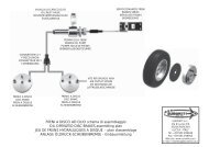
I cilindri dei carrelli <strong>Professional</strong> <strong>Line</strong>, potendo funzionare ad olio o ad aria singolo o doppio<br />
effetto, sono dotati alle estremità di due attacchi rapidi per l’innesto della tubazione. Per<br />
convenzione negli schemi di collegamento degli impianti olio/aria chiameremo questi attacchi<br />
“apertura” e “chiusura” riferendoci alla fasi di apertura e chiusura del carrello.<br />
Carrello 120° orientabile<br />
Carrello 120° fisso<br />
Carrello 95° orientabile<br />
Carrello 95° fisso<br />
Carrello gamba ruotante<br />
Chiusura carrello<br />
Chiusura carrello<br />
Apertura carrello<br />
Apertura carrello<br />
Apertura carrello<br />
Apertura carrello<br />
Apertura carrello<br />
Chiusura carrello<br />
Chiusura carrello<br />
Chiusura carrello<br />
IT ITALIANO<br />
IT ITALIANO<br />
ALIANO
EUROKIT thank you for choosing their products and warmly<br />
recommend for a proper use of these landing gears to follow<br />
the instructions included in this handbook.<br />
INSTRUCTIONS - PRECAUTIONS<br />
These landing gears are intended for model aircrafts only<br />
and should be used by expert pilots.<br />
Teen-agers under 12 years are advised against using these<br />
landing gears unless under a grown-up’s guidance.<br />
The ready-to-use undercarriage system contains high-pressurized<br />
oil or air, so DO NOT take out the tubing when the<br />
system is under pressure.<br />
DO NOT put your hand to nor hold the landing gears when<br />
they are in operation.<br />
Air pressure in the tanks must not exceed 10 bar.<br />
DO NOT let the landing gears work at low pressure or they<br />
would not move correctly.<br />
In case of leakage or faults of any part of the system, DO<br />
NOT make the landing gears work before having the fault<br />
repaired.<br />
Non-observance of these instructions/precautions may cause<br />
injury to persons or cause unproper operation.
INTRODUCTION<br />
The <strong>Professional</strong> <strong>Line</strong> is a new line of dural-made retractable landing gears. The mechanism has<br />
been completely redesigned and improved, and it can operate with an hydraulic oil circuit, like in<br />
the real aircrafts, or with compressed air. This new line is expressely designed to meet the<br />
requirements of the most demanding modelers, especially in the turbine jet models.<br />
An electrical gear pump in the oil system forces the fluid from the tank in the cylinder of the<br />
landing gears, and sets the leg bearing cam in motion: a mechanical two-way distributor controls<br />
the landing gear’s opening/closing, while an electronic control unit steadily monitors the system<br />
to disconnect the electric pump just at the end of the pull-in/pull-out travel.<br />
The air operating mode can be “single-action” (L/G pulled in by air-pressure and pulled out by<br />
a return spring situated in the cylinder), or “double action” (air-operated L/G’s opening/closing.<br />
Although the spring is not necessary in this mode, it is advisable to keep it in place to ensure<br />
automatic L/G pull-out in case of air leckage). The <strong>Professional</strong> <strong>Line</strong> comes in three sizes: SMALL,<br />
MEDIUM, and LARGE, to fit 5-6, 10-12, and up to 20 Kg. respectively.<br />
Each size comes with two types of mechanism: in one, the leg retracts to the opposite side of the<br />
cylinder and the pull-in travel is adjustable within 90 and 120 degrees to allow the leg, and the<br />
wheel, to get completely into the fuselage (Photo-1-2). The leg/wheel unit can be steerable in the<br />
front L/G (Photo 1-3) or fixed in the main L/G (Photo 2-4). In the other version the leg retracts<br />
against the cylinder and the pull-in travel is 90 degrees (Photo 3-4).<br />
In either mechanisms, the open position, which is usually 90°, can be set +/- 5° so that we can<br />
select a continuous opening range between 85 and 95 degrees.<br />
Photo 1 Photo 2 Photo 3 Photo 4<br />
This adjustment is very easy in the oil-circuit mode: just shift the landing gear end-travel point to<br />
get the desired opening amount: since oil is not compressible, the cam will stop in whichever<br />
position whether in the opening or in the closing process. If, on the contrary, your system is an<br />
air-operated one (single or double action), you must replace the cam choosing among the available<br />
ones; this is necessary because the air, being compressible, cannot lock the cam exactly into the<br />
opening/closing positions and, for this reason, the cam must be stopped mechanically.<br />
Another type of landing gear, belonging to <strong>Professional</strong> <strong>Line</strong>,<br />
is available, i.e. that one in which the wheel can turn 90° on its<br />
own axle while it is pulled in to get into its wing or fuselage<br />
compartment (Photo 5). The pull-in position of this L/G can be<br />
set between 90° and 100°. This landing gear is available in<br />
Photo 5 three versions as well: SMALL, MEDIUM, and LARGE.<br />
ENGLISH<br />
ENGLISH
ADJUSTING THE L/G MOVEMENT<br />
In this section we are going to describe how to adjust the movement of the cams in order to obtain<br />
the required pull-in / pull-out. We recommend to use thread stoppers on screws A, in order to<br />
prevent from vibration-induced loosening.<br />
120° LANDING GEAR (Photo 6-7-8)<br />
Adjusting the pull-out position (Photo 6):<br />
In the pressurized oil-system it is sufficient to unscrew or<br />
screw in A until the desired pull-out amount is obtained<br />
(adjustment range 85-95°).<br />
In the air operating mode your L/G must have a cam suited<br />
for the required opening degrees. Pull out the L/G<br />
completely and adjust screw A drawing it close to the<br />
cam.<br />
Adjusting the pull-in position:<br />
In either mode, oil or air, pulling-in is adjusted by<br />
loosening the two screws B and shifting spacer C<br />
downwards completely, to get a 90° retracting<br />
(compared with the standard 90°)(Photo 7), or<br />
completely upwards to get a 120° retracting (Photo<br />
8). A pull-in between 90° and 120° is obtained by<br />
fixing the spacer into the intermediate positions.<br />
95° LANDING GEAR (Photo 9)<br />
Adjusting the pull-out position:<br />
In the pressurized oil-system just unscrew or screw<br />
A as to reach the desired opening amount (adjustment<br />
range 85-95°)<br />
In the air operating mode your L/G must have a cam<br />
suited for the required pull-out degrees. Pull-out the<br />
L/G completely and adjust screw A, drawing it close<br />
to the cam.<br />
Adjusting the pull-in position:<br />
In this type of L/G the pull-in position is 90° is fixed<br />
and cannot be adjusted.<br />
A<br />
C<br />
A<br />
B<br />
Photo 6<br />
Photo 7<br />
Photo 8<br />
Photo 9
90° ROTATING LEG LANDING GEAR (Photo 10)<br />
Adjusting the pull-out position:<br />
Screw or unscrew A as to get the required pull-in<br />
(adjustment range 90-100°)<br />
Adjusting the pull-in position:<br />
In this type of L/G the pull-out position is fixed at<br />
90° and cannot be adjusted.<br />
A<br />
Photo 10<br />
ASSEMBLING THE LANDING GEAR SYSTEM<br />
Other than the landing gears belonging to the Classic <strong>Line</strong> or Classic <strong>Line</strong> Pro, the L/G of<br />
<strong>Professional</strong> <strong>Line</strong> are sold individually to allow the user to choose among a number of combinations:<br />
forwards or backwards travel, steerable or fixed. You can thus set up a trike or a main L/G suiting<br />
your model’s features.<br />
Concerning the operation mode (oil or air) of the L/G, ready-assembled inclusive kits (trikes,<br />
pairs) are also available (Photos 11-12-13-14-15-16).<br />
Photo 11 - RCA/15946/000 Oil kit for trikes. Photo 12 - RCA/15947/000 Oil kit for couples.<br />
Photo 13 - RCA/15950/000 Air kit for double<br />
action trikes.<br />
Photo 14 - RCA/15951/000 Air kit for double<br />
action couples.<br />
ENGLISH<br />
ENGLISH
Photo 15 - RCA/15948/000 Air kit for single<br />
action trikes.<br />
Photo 16 - RCA/15949/000 Air kit for single<br />
action couples.<br />
Since the L/G belonging to the <strong>Professional</strong> <strong>Line</strong> can be air or oil-operated, single or doubleaction,<br />
they are equipped of nipples at their ends, for piping quick connection. In our connecting<br />
diagrams these attachment points are marked “open”, “close”, meaning the landing gear’s pullout,<br />
pull-in.<br />
L/G Close<br />
Steerable 120° L/G<br />
Fixed 120° L/G<br />
Steerable 95° L/G<br />
Fixed 95° L/G<br />
Rotating leg L/G<br />
L/G Close<br />
L/G Open<br />
L/G Open<br />
L/G Open<br />
L/G Open<br />
L/G Open<br />
L/G Close<br />
L/G Close<br />
L/G Close
Nous vous remercions pour l’attention dediée à nos produits<br />
et nous vous conseillons de suivre attentivement les<br />
instructions et indications de ce manuel pour la bonne<br />
utilisation de nos trains d’atterrissage.<br />
RECOMMANDATIONS ET<br />
PRECAUTIONS<br />
L’utilisation de ces trains d’atterrissage est reservée aux pilots<br />
expérimentés et ils sont à utiliser exclusivement dans le<br />
modélisme aérien.<br />
Nous en déconseillons l’usage aux mineurs de 12 ans à moins<br />
qu’ils ne soient assistés par un adulte.<br />
L’installation prête à l’usage contenant de l’huile ou de l’air<br />
sous haute pression, il ne faut pas détacher les tubes lorsque<br />
l’installation est en pression.<br />
Ne vous approchez pas des trains ni tâchez pas d’en retenir les<br />
jambes lorsque ceux-ci sont en fonction.<br />
Ne pas charger les reservoirs d’air comprimé à plus de 10 bar.<br />
Eviter de faire fonctionner les trains à basse pression, parce<br />
que dans ce cas la retraction ne se passerait pas correctement.<br />
En cas d’endommagement d’une partie de l’installation ou en<br />
présence de pertes d’air, réparer l’installation avant de l’utiliser.<br />
La non observance de ces règles pourrait donner lieu à des<br />
dommages aux personnes ou à mauvais fonctionnement des<br />
trains d’atterrissage.<br />
FRANCAIS<br />
FRANCAIS
INTRODUCTION<br />
La <strong>Professional</strong> <strong>Line</strong> est une nouvelle gamme de trains rentrants fabriqués complètement en Dural.<br />
La mécanique, réalisée d’après un nouveau projet, peut fonctionner soit avec un circuit hydraulique<br />
à huile, comme dans les vrais avions, soit par air comprimé. Cette ligne de trains est spécialement<br />
conçue pour satisfaire les exigences des modélistes expérimentés, notamment dans le secteur des<br />
turboréacteurs.<br />
Dans le fonctionnement par circuit hydraulique (huile) une pompe électrique à engrenages envoie<br />
le fluide du réservoir aux cylindres des trains, actionant les cames. Une soupape mécanique à<br />
deux voies gouverne la rentrée ou la sortie des trains, tandis qu’un régulateur électronique coupera<br />
la pompe électrique aussitôt que les train sont complètement rentrés ou sortis.<br />
Le foncionnement par air comprimé, par contre, peut être à simple action (rentrée par l’action de<br />
l’air comprimé, sortie grâce au ressort de rappel), ou double action, c’est-à dire rentrée et sortie<br />
par action de l’air comprimé. Dans ce dernier cas le ressort n’est plus necessaire; toutefois, s’il<br />
est laissé à sa place, il pourra toujours intervenir en cas de perte d’air du circuit, garantissant<br />
l’ouverture automatique des trains. Les trains d’atterrissage de la gamme <strong>Professional</strong> <strong>Line</strong> sont<br />
disponibles en trois tailles: P’TIT- GROS, MOYEN ET GROS, respectivement pour les modèles<br />
jusqu’à 5-6 Kg., 10-12 Kg. et jusqu’à 20 Kg.<br />
Chaque version peut fonctionner avec deux types de mécanique: une avec jambe rentrante du<br />
côté opposé au cylindre et course règlable entre 90° et 120°, ce qui permet à la jambe (et la roue),<br />
orientable dans le train avant (photo 1) fixe dans les trains d’aile (photo 2), de trouver place<br />
complètement dans le fuselage. Une seconde version avec jambe rentrante vers le cylindre et<br />
excursion de 90° (photo 3-4).<br />
Dans les deux mécaniques la position train sorti, normalement de 90°, pouvant être réglée de +/-<br />
Photo 1 Photo 2 Photo 3 Photo 4<br />
5°, il est donc possible d’obtenir des ouvertures de train de 85°-86°-87°…..95°. Réglage très<br />
simple pour les installations à huile: on n’a qu’à déplacer le fin de course du train pour obtenir le<br />
degré d’ouverture désiré. L’huile n’étant pas compressible, la came du train s’arrête mécaniquement<br />
dans n’importe quelle position, que le train rentre ou qu’il sort. Si, par contre, on utilise un<br />
circuit à air comprimé (single ou double action), pour obtenir les différents ouvertures il faut<br />
remplacer la came choisissant parmi celles disponibles: en effet l’air, qui peut être comprimé, ne<br />
reussit pas à bloquer parfaitement les cames et, pour cette raison, il est nécessaire de réaliser sur<br />
celles-ci un verrouillage mécanique.<br />
Un autre type de train est inclus dans la <strong>Professional</strong> <strong>Line</strong>: celui<br />
qui monte une roue tournante sur son essieu lors de la rentrée<br />
du train, de manière que l’ensemble roue-jambe peut se loger<br />
complètement dans le fuselage ou dans l’aile (photo 5). La<br />
rentrée de ce train est réglable entre 90° et 100° et il est<br />
Photo 5 disponible également dans les tailles P’TIT-GROS, MOYEN,<br />
GROS.
RÉGLAGE DU MOUVEMENT DES TRAINS<br />
Dans cette section nous allons montrer comme on fait le réglage du mouvement des cames afin<br />
d’obtenir les rentrées et sorties désirées. Nous conseillons de monter des arrêts de filets sur les<br />
vis A pour éviter que celles-ci ne se relâchent à cause des vibrations.<br />
TRAIN D’ATTERRISSAGE 120° (photos 6-7-8)<br />
Réglage de la position train sorti (photo 6):<br />
Dans le fonctionnement à huile il suffit de visser ou dévisser<br />
la vis A jusqu’à obtenir l’ouverture désirée (champ de<br />
réglage 85°-95°).<br />
En fonctionnement pneumatique il est indispensable de se<br />
procurer un train équipé d’une came indiquée pour les<br />
degrés d’ouverture désirés, faire sortir le train<br />
complètement et régler la vis A jusqu’à ce que celleci<br />
ne touche la came.<br />
Réglage de la position train rentré:<br />
Le réglage de la position train rentré est le même pour<br />
les deux systèmes. Desserrer les deux vis B et<br />
déplacer à fond, en bas, l’entretoise C pour atteindre<br />
une rentrée de 90° (par rapport à la position<br />
d’ouverture standard de 90°)(photo 7), ou bien<br />
complètement en haut pour une rentrée de 120°<br />
(photo 8). En bloquant l’entretoise dans une des<br />
positions intermédiaires on obtiendra des rentrées<br />
de train comprises entre 90° et 120°.<br />
TRAIN D’ATTERRISSAGE 95° (photo 9)<br />
Réglage de la position train sorti:<br />
En cas de train actionné par huile il suffit de visser ou<br />
dévisser la vis A jusqu’à obtenir l’ouverture désirée<br />
(champ de réglage 85°-95°). En fonctionnement<br />
pneumatique il faut se procurer un train avec une came<br />
indiquée pour les degrés d’ouverture désirés, faire sortir<br />
le train complètement et régler la vis A jusqu’à ce que<br />
celle-ci ne touche la came.<br />
Réglage de la position train rentré:<br />
Dans ce type de train la came est fixe sur 90° est le<br />
réglage n’est pas possible.<br />
A<br />
C<br />
A<br />
B<br />
Photo 6<br />
Photo 7<br />
Photo 8<br />
Photo 9<br />
FRANCAIS<br />
FRANCAIS
TRAIN JAMBE TOURNANTE 90° (photo 10)<br />
Réglage position train sorti:<br />
Serrez ou desserrez les vis A jusqu'à obtenir<br />
l'ouverture désirée (champs de réglage 90-100°).<br />
Réglage position train rentré:<br />
La position de train rentré étant fixe dans ce train,<br />
aucun réglage n'est possible.<br />
COMPOSITION DE L’INSTALLATION TRAINS D’ATTERRISSAGE<br />
Les trains de la <strong>Professional</strong> <strong>Line</strong> ne sont pas vendus par deux ou par trois comme ceux de la<br />
Classic <strong>Line</strong> ou Classic <strong>Line</strong> Pro, mais à l’unité, cela pour permettre de choisir entre plusieurs<br />
combinaisons, mouvement en avant ou en arrière, jambes orientables ou fixes, pour les adapter au<br />
modèle dont on dispose.<br />
Selon le fonctionnement, huile ou air, des trains à trois ou deux jambes complets d’accessoires<br />
sont disponibles (photos 11-12-13-14-15-16).<br />
Photo 11 - RCA/15946/000 Boite oléodinamique<br />
pour atterrisseur triple.<br />
Photo 13 - RCA/15950/000 Boite air comprimé<br />
double effect pour atterrisseur triple.<br />
A<br />
Photo 10<br />
Photo 12 - RCA/15947/000 Boite oléodinamique<br />
pour atterrisseur double.<br />
Photo 14 - RCA/15951/000 Boite air comprimé<br />
double effect pour atterrisseur double.
Photo 15 - RCA/15948/000 Boite air comprimé<br />
single effect pour atterrisseur triple.<br />
Photo 16 - RCA/15949/000 Boite air comprimé<br />
single effect pour atterrisseur double.<br />
Les cylindres des trains <strong>Professional</strong> <strong>Line</strong> pouvant être actionnés soit par air (single ou double<br />
action) soit par huile, possèdent de raccords rapides pour l’insertion des tuyaux. Dans nos plans<br />
de connexion des systèmes huile/air ces raccords sont indiqué par “ouvert”, “fermé”, signifiant,<br />
bien entendu, les phase de “sortie du train” et de “rentrée du train”.<br />
Train 120° orientable<br />
Train 120° fixe<br />
Train 95° orientable<br />
Train 95° fixe<br />
Train jambe tournante<br />
Train fermé<br />
Train fermé<br />
Train ouvert<br />
Train ouvert<br />
Train ouvert<br />
Train ouvert<br />
Train ouvert<br />
Train fermé<br />
Train fermé<br />
Train fermé<br />
FRANCAIS<br />
FRANCAIS
Die Fa. <strong>Eurokit</strong> SrL bedankt sich für Ihr Interesse, welches Sie<br />
dem Produkt entgegenbringen, und empfiehlt, die in dieser<br />
Anleitung enthaltenen Anweisungen zu beachten.<br />
ANWEISUNGEN UND<br />
VORSICHTSMASSNAHMEN<br />
Diese Fahrwerke dürfen nur von erfahrenen Modellpiloten<br />
benutzt und ausschließlich in Flugzeugmodellen eingesetzt<br />
werden. Jugendliche unter 12 Jahren sollten nur unter der<br />
Aufsicht von erwachsenen Personen damit umgehen.<br />
Schläuche nicht ahnehmen, solange sich die Fahrwerkanlage<br />
unter Druck befindet, denn diese sind mit Luft oder Öl unter<br />
hohem Druck gefüllt. Bitte halten Sie immer zur Anlage den<br />
nötigen Abstand. Fahrwerkbeine nicht zurückhalten, solang<br />
diese sich in Betrieb befinden.<br />
Luftflaschen nicht überladen! Maximaler Druck: 10 bar.<br />
Fahrwerke nicht in Betrieb setzen, wenn der Druck allzu niedrig<br />
ist, das könnte der ordungsmässen Funktion schädlich sein.<br />
Fahrwerke nur dann benutzen, wenn sie sich in einwandfreiem<br />
Zustand befinden.<br />
Die Nichtbefolgung dieser Hinweise könnte Personenschäden
EINLEITUNG<br />
<strong>Professional</strong> <strong>Line</strong> ist einer neue Serie von neu entworfenen verbesserten Fahrwerken aus Dural,<br />
die sowohl mit Preßluft als auch mit Öl (so wie in den echten Flugzeugen) betätigt werden können.<br />
Diese neue Linie von Fahrwerken kommt den Anforderungen der erfahrensten Modellpiloten<br />
nach, insbesondere im Gebiet der Turbinenflieger.<br />
Bei der hydraulischen Betriebsweise wird die in der Anlage enthaltene Flüßigkeit (Spezialöl)<br />
durch eine elektrische Zahnradpumpe aus dem Öltank an die Fahrwerkzylinder getrieben und<br />
betätigt somit die Nocken, an denen die Beine mit dem Rad befestigt sind. Für das Ein- und<br />
Ausfahren des Fahrwerkes sorgt ein Zweiwege-Ventil, während eine elektronische Steureinheit<br />
die Pumpe ausschaltet, sobald die Endlaufstellungen erreicht werden.<br />
Die Preßluftbetriebsweise kann sowohl einfach ( Luft betriebenes Einfahren, Rückholfeder<br />
bewirktes Ausfahren) als doppelwirkend (beides, Ein-und Ausfahren, durch Preßluft, wobei die<br />
Rückholfeder überflüßig ist. Wird jedoch diese Feder an ihrer Stelle belassen, so kann man bei<br />
Undichte jederzeit mit einer sicheren Landung rechnen, da durch die Federwirkung ein Ausfahren<br />
des Fahrwerkes gesichert wird).<br />
Die Fahrwerke der <strong>Professional</strong> <strong>Line</strong> werden in drei Formaten angeboten: KLEIN, MITTELGROß<br />
und GROß, d.h. diese sind für Modelle mit 5-6 bzw. 10-12 und 20 Kg Gewicht ausgelegt, Jede<br />
dieser Version ist mit zweierlei Mechanik lieferbar: einer, in welcher das Bein in die dem Zylinder<br />
entgegengesetzten Richtung ausfährt und dessen Einschwenkwinkel zwischen 90 und 120 Grad<br />
einstellbar ist, wobei Bein und Rad in dem Rumpf aufenommen werden; in dieser Version ist das<br />
Bugfahrwerk lenkbar (Abb.1), das Hauptfahrwerk unlenkbar (Abb.2). Eine zweite Version, in<br />
der das Bein 90 Grad gegen den Zylinder einschwenkt (Abb.3-4).<br />
In beiden Mechaniken ist die Auszieh-Stellung (normaleweise 90 Grad) um ? 5 Grad verstellbar;<br />
dies ermöglicht alle Ausfahrwinkel im Bereich 85-86-87-……bis 95 Grad.<br />
Abb.1 Abb.2 Abb.3 Abb.4<br />
Diese Einstellung ist sehr einfach bei der Hydraulik-Version: man braucht nur den Fahrwerkendlauf<br />
zu verstellen bis die gewünschte Öffnung erreicht ist (Da Öl nicht verdichtbar ist, die Nocken des<br />
Fahrwerks läßt sich mechanisch in jeder beliebiger Stellung blockieren sowohl einfahrend als<br />
auch ausfahrend).<br />
Im Preßluftbetrieb (einfach oder doppelwirkend) ist das Erlangen des gewünschten<br />
Öffnungswinkelserst möglich, wenn man eine andere Nocke einsetzt, da die komprimierbare<br />
Luft<br />
nicht imstande ist, die Nocken in der gewollten Stellung zu blockieren; deshalb bedarf es einer<br />
mechanischen Sperre auf der Nocke. Zu der <strong>Professional</strong> <strong>Line</strong> gehört ferner ein weiterer Typ von<br />
Fahrwerk, und zwar das mit dem beim Einziehen um 90 Grad drehbaren Bein; diese Eigenschaft<br />
ermöglicht das Einlagern des Beines samt Rad in den Rumpf<br />
(Abb.5). Das Ausfahren dieses Fahrwerkes, das ebenso in den<br />
Formaten KLEIN, MITTELGROß und GROß lieferbar ist,<br />
kann zwischen 90 und 120 Grad eingestellt werden.<br />
Abb. 5<br />
DEUTSCH<br />
DEUTSCH
EINSTELLEN DER FAHRWERKE<br />
In diesem Abschnitt wird gezeigt, wie die Nockenbewegung eingestellt werden kann, um die<br />
gewünschten Auszih- und Einziehwinkel zu erhalten. Der Einsatz von Gewindesperren ist ratsam,<br />
um vibrationsbedingtes Losrütteln vorzubeugen.<br />
120 GRAD FAHRWERK (Abb. 6-7-8)<br />
Einstellen des Ausfahrwinkels (Abb.6):<br />
Im hydraulischen Betrieb Schraube A einfach ein- oder<br />
aufdrehen bis die gewünschten Öffnungswinkel erreicht<br />
sind (Regulierungsbereich 85 bis 95 Grad).<br />
Im Preßluftbetrieb muß man sich ein Fahrwerk mit der<br />
passenden Nocke anschaffen, das Fahrwerk komplett<br />
Ausfahren und Schraube A einstellen, bis diese an<br />
die Nocke heranrreicht.<br />
Einstellen des Einfahrwinkels:<br />
In beiden Betriebsweisen, Luft oder Öl, erfolgt die<br />
Einstellung durch Aufdrehen der zwei Schrauben B<br />
und Verschieben des Zwischenstückes C ganz nach<br />
unten für eine 90 Grad Schliessen (bezogen auf die<br />
90° Standardöffnungsstellung, Abb.7) oder ganz<br />
aufwärts, um eine Schliessung von 120° zu erlangen<br />
(Abb.8). Durch das Einsetzen eines<br />
Zwischenstückes erhalten wir einen Einziehwinkel<br />
zwischen 90° und 120°.<br />
95 GRAD FAHRWERK (Abb.9)<br />
Einstellen des Ausfahrwinkels:<br />
Im hydraulischen Betrieb Schraube A einfach ein- oder<br />
aufdrehen bis die gewünschten Ausfahrwinkels erreicht<br />
sind (Regulierungbereich 85° bis 95°).<br />
Im Preßluftbetrieb muß man sich ein Fahrwerk mit der<br />
passenden Nocken anschaffen, das Fahrwerk komplett<br />
Ausfahren und Schraube A einstellen, bis diese an die<br />
Nocke anchließt.<br />
Einstellen des Einfahrwinkels:<br />
Die ZU-Stellung ist hier fest auf 90° und kann nicht geändert werden.<br />
A<br />
C<br />
A<br />
B<br />
Abb.6<br />
Abb.7<br />
Abb.8<br />
Abb.9
DREHBARES (90°) FAHRWERKSBEIN (Abb.10)<br />
Einstellen des Ausfahrwinkels<br />
Schraube A einfach ein- oder aufdrehen bis die<br />
gewünschten Öffnungswinkel erreicht sind<br />
(Regulierungbereich 90° bis 100°).<br />
Einstellen des Einfahrwinkels:<br />
Die ZU-Stellung ist hier fest auf 90° und kann nicht<br />
geändert werden.<br />
ZUSAMMENSETZUNG DER FAHRWERKANLAGE<br />
Die zu der <strong>Professional</strong> <strong>Line</strong> gehörigen Fahrwerke werden nicht als dreier, zweier Fahrwerke,<br />
wie es bei der Classic <strong>Line</strong> oder Classic <strong>Line</strong> Pro der Fall ist, sondern einzeln geliefert. Dies<br />
ermöglicht, die verschiedenen erhältlichen Fahrwerke (drehbar nach vorne, nach hinten, lenkbar,<br />
nicht lenkbar)<br />
Beliebig zu kombinieren, um sie dem jeweiligen Modell am besten anzupassen. Je nach Funktion<br />
(Öl oder Luft) fertige Baukästen zweier und dreier Fahrwerke mit komplettem Zubehör sind<br />
abenso lieferbar (Abb. 11-12-13-14-15-16).<br />
Abb.11 - RCA/15946/000 Baukasten Öldrucksytem<br />
für Dreiradfahrwerke.<br />
Abb.13 - RCA/15950/000 Baukasten Doppelwirkung-Preßluftsystem<br />
für Dreiradfahrwerke.<br />
A<br />
Abb.10<br />
Abb.12 - RCA/15947/000 Baukasten Öldrucksystem<br />
für Zweiradfahrwerke.<br />
Abb.14 - RCA/15951/000 Baukasten Doppelwirkung-Preßluftsystem<br />
für Zweiradfahrwerke.<br />
DEUTSCH<br />
DEUTSCH
Abb.15 - RCA/15948/000 Baukasten Einzelwirkung-Preßluftsystem<br />
für Dreiradfahrwerke.<br />
Abb.16 - RCA/15949/000 Baukasten Einzelwirkung-Preßluftsystem<br />
für Zweiradfahrwerke.<br />
Da die Zylinder der Fahrwerke der <strong>Professional</strong> <strong>Line</strong> sowohl mit Öl als auch mit Luft, “single”<br />
und “double effect”, funktionieren, besitzen sie an beiden Enden zwei Schnellverbindungen zum<br />
Einstecken der Schläuche. In unseren Verbindungsplänen bezeichnen wir diese Verbindungen<br />
mit den Stichworten “Öffnen” und “Schließen”, wobei das Ausfahren und das Einfahren des<br />
Fahrwerkes gemeint ist.<br />
Fahrwerke Schließen<br />
Fahrwerke 120° lenkbar<br />
Fahrwerke 120° unlenkbar<br />
Fahrwerke 95° lenkbar<br />
Fahrwerke 95° unlenkbar<br />
Fahrwerke mit lenkbarem<br />
bein<br />
Fahrwerke Schließen<br />
Fahrwerke Öffnen<br />
Fahrwerke Öffnen<br />
Fahrwerke Öffnen<br />
Fahrwerke Öffnen<br />
Fahrwerke Öffnen<br />
Fahrwerke<br />
Schließen<br />
Fahrwerke<br />
Schließen<br />
Fahrwerke<br />
Schließen
DEUTSCH<br />
DEUTSCH
EUROKIT S.r.L.<br />
Via di Lucia 3/A<br />
55016 PORCARI<br />
LUCCA - ITALY<br />
Tel. +39 0583 299944<br />
Fax +39 0583 299953<br />
E-mail: modelling@eurokitlucca.it<br />
Per aggiornamenti su nuovi prodotti, cataloghi, istruzioni consultate regolarmente<br />
il nostro sito Web all’indirizzo: www.eurokitlucca.it<br />
For New Product Up-dating, catalogues, instructions please visit our Web<br />
Site under: www.eurokitlucca.it<br />
Prenez vision des nouveautés, catalogues, notices en consultant notre page<br />
web à l’adresse: www.eurokitlucca.it<br />
Besuchen Sie uns bitte unter www.eurokitlucca.it, um Einsicht in unsere<br />
neuen Produkte, Kataloge, Informationen zu nehmen.<br />
October 2004 revision