SPECIFICO ROLL-IN - Everlasting
SPECIFICO ROLL-IN - Everlasting
SPECIFICO ROLL-IN - Everlasting

You also want an ePaper? Increase the reach of your titles
YUMPU automatically turns print PDFs into web optimized ePapers that Google loves.
Capitolo 1 NORME ED AVVERTENZE GENERALI<br />
Section 1 STANDARDS AND GENERAL WARN<strong>IN</strong>GS<br />
Chapitre 1 NORMES ET AVERTISSEMENTS GENERAUX<br />
Kap. 1 NORMEN UND ALLGEME<strong>IN</strong>E H<strong>IN</strong>WEISE<br />
1.1 DICHIARAZIONE DI CONFORMITA' - DECLARATION OF CONFORMITY<br />
DECLARATION DE CONFORMITE - KONFORMITÄTSERKLÄRUNG<br />
Suzzara ................................<br />
DICHIARAZIONE CE DI CONFORMITA'<br />
CE DECLARATION OF CONFORMITY<br />
DECLARATION CE DE CONFORMITE<br />
KONFORMITÄTSERKLÄRUNG<br />
NOI - THE COMPANY - NOUS - DIE FIRMA<br />
EVERLAST<strong>IN</strong>G S.R.L. - Fabbrica Frigoriferi Industriali<br />
S.S. Cisa km. 161 - 46029 SUZZARA ( MN ) - ITALIA<br />
Dichiariamo sotto la nostra esclusiva responsabilità che il prodotto ARMADIO REFRIGERATO<br />
Declares, under its own sole responsibility, that the product designated REFRIGERATED CAB<strong>IN</strong>ET<br />
Déclarons sous notre responsabilité exclusive que le produit ARMOIRE REFRIGEREE<br />
Erklärt unter der eigenen und ausschließlichen Verantwortung, daß das Produkt KÜHLSCHRANK<br />
Numero di serie<br />
Serial number<br />
Numéro de série<br />
Seriennummer<br />
al quale questa dichiarazione si riferisce è conforme alle seguenti direttive europee:<br />
to which the present declaration refers, complies with the following european directives:<br />
auquel cette déclaration se rapporte, est conforme aux dispositions européennes suivantes:<br />
auf das sich diese Erklärung bezieht, den folgende europäische Richtlinien entsprechen:<br />
"Macchine" 2006/42/CE<br />
"Bassa tensione" 2006/95/CEE e successive modificazioni<br />
"Compatibilità elettromagnetica" 2004/108/CEE e successive modificazioni<br />
"Materiali ed oggetti destinati a venire in contatto con i prodotti alimentari" 89/109/CEE<br />
"Direttiva 97/23/CE" (PED - Pressure Equipment Directive) apparecchi in classe 1<br />
"Machines" 2006/42/CE<br />
"Low voltage" 2006/95/EEC and subsequent modifications<br />
"Electromagnetic Compatibility" 2004/108/EEC and subsequent modifications<br />
"Materials and objects designed to come into contact with foodstuff" 89/109/EEC<br />
"Directive 97/23/EC" (PED - Pressure Equipment Directive) appliances in class 1<br />
"Machines" 2006/42/CE<br />
"Basse Tensions" 2006/95/CEE et modifications successives<br />
"Compatibilité Electromagnétique" 2004/108/CEE et modifications successives<br />
"Matériels et objets destinés à entrer en contact avec des produits alimentaires" 89/109/CEE<br />
"Directive 97/23/CE" (PED - Pressure Equipment Directive) appareils en class 1<br />
"Maschinen" 2006/42/CE<br />
"Niaderspannung" 2006/95/EG und nachfolgende Änderungen<br />
"Elektromagnetische Verträglichkeit" 2004/108/EG und nachfolgende Änderungen<br />
"Zum Umgang mit Nahrungsmitteln bestimmte Materialien und Gegenstände" 89/109/EG<br />
"Richtlinie 97/23/EG" (PED - Pressure Equipment Directive) Geräte in Klasse 1<br />
La persona autorizzata a costituire il fascicolo tecnico è Paolo Guidetti, legale rappresentante della ditta<br />
EVERLAST<strong>IN</strong>G S.R.L. S.S. CISA KM 161 – 46029 SUZZARA (MN) – ITALIA, sede presso la quale è anche custodito.<br />
The person authorized to constitute the technical file is Paolo Guidetti, legal representative of the Company<br />
EVERLAST<strong>IN</strong>G S.R.L. S.S. CISA KM 161 – 46029 SUZZARA (MN) – ITALY, where the file is kept.<br />
La personne autorisée à constituer le dossier technique est Paolo Guidetti, représentant légal de la société<br />
EVERLAST<strong>IN</strong>G S.R.L. S.S. CISA KM 161 – 46029 SUZZARA (MN) – ITALIE, ou le dossier est conservé.<br />
Die Person die berechtigt ist die technische Unterlagen zusammenzustellen ist Paolo Guidetti, gesetzlicher Vertreter der Firma<br />
EVERLAST<strong>IN</strong>G S.R.L. S.S. CISA KM 161 – 46029 SUZZARA (MN) – ITALIEN, wo die Datei gehalten wird.<br />
2<br />
.........................................<br />
<strong>ROLL</strong>.02
<strong>ROLL</strong>.02<br />
Cap. 8 Istruzioni per l'utilizzatore 4<br />
8.1 Comandi................................................................. 4<br />
8.2 Indicazioni relative all’uso ...................................... 4<br />
Sect. 8 User instructions 6<br />
8.1 Controls.................................................................. 6<br />
8.2 Operation ............................................................... 6<br />
Chap. 8 Instructions pour l'utilisateur 8<br />
8.1 Commandes........................................................... 8<br />
8.2 Indications relatives à l'utilisation ........................... 8<br />
Kap. 8 Benutzeranleitungen 10<br />
8.1 Bedienung ............................................................. 10<br />
8.2 Gebrauchshinweise ............................................... 10<br />
ITALIANO<br />
Indice generale<br />
ENGLISH<br />
Content<br />
FRANÇAIS<br />
Index général<br />
DEUTSCH<br />
Inhaltsverzeichnis<br />
3<br />
Modelli disponibili 12<br />
Tabella 1 caratteristiche tecniche 12<br />
Schemi elettrici 13<br />
Models 12<br />
Table 1 technical features 12<br />
Wiring diagrams 13<br />
Modèles 12<br />
Tableau 1 caractèristiques tèchniques 12<br />
Schémas électriques 13<br />
Modell 12<br />
Tabelle 1 Teknische Mekmale 12<br />
Elektronische Bedienung 13
ITALIANO<br />
Capitolo 8 ISTRUZIONI PER L’UTILIZZATORE<br />
4<br />
<strong>ROLL</strong>.02<br />
Le informazioni contenute in questo capitolo sono destinate all’utilizzatore oppure a personale non specializzato (vedi par. 1.3 Manuale<br />
d’uso e manutenzione).<br />
Una volta installata, secondo le istruzioni di cui al cap. 3 (vedi Manuale d’uso e manutenzione), la macchina è da considerare pronta<br />
all’uso.<br />
8.1 COMANDI<br />
A seconda dei modelli la macchina verrà fornita di combinazioni diverse di comandi:<br />
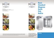
8.1.1 Descrizione dei comandi e pulsanti ( Fig. 10)<br />
Il pannello di comando è un termoregolatore digitale per il freddo<br />
ed è provvisto di 4 pulsanti con funzioni specifiche:<br />
I comandi di cui è dotata la macchina sono :<br />
display (11) visore di temperatura e dello stato di funzionamento<br />
della macchina<br />
Tasto SET (13) accede al Set-point, conferma i parametri modificati.<br />
Se premuto per oltre 4 secondi porta in standby l’armadio,<br />
spegnendo il display e disattivando tutte le uscite digitali.<br />
Tasto neutro (12) in questa applicazione il tasto non è abilitato.<br />
Tasto UP (6) consente l’incremento dei valori, (temperatura più<br />
alta) e, se premuto per 4 secondi all’attivazione manuale del ciclo<br />
di sbrinamento. In combinazione con il tasto down permette di<br />
visualizzare il menù parametri.<br />
Tasto DOWN (5) consente il decremento dei parametri, (temperatura<br />
più bassa). Se premuto per 4 secondi consente di visualizzare la<br />
temperatura della sonda evaporatore. Se premuto, in combinazione<br />
con il tasto set il display visualizzerà LO e la tastiera sarà bloccata,<br />
non sarà consentita nessuna modifica. Premere nuovamente<br />
entrambi i tasti contemporaneamente per sbloccare la tastiera il display visualizzerà UN.<br />
Se premuto, in combinazione con il tasto UP per 4 secondi si accede al menù programmazione, protetto da password. Per accedere<br />
ai parametri premere SET, inserire la password -19, premere il tasto SET per confermarla e premere contemporaneamente i tasti UP<br />
e DOWN per 4 secondi il display indicherà d’essere nel menù visualizzando il primo parametro SP. Premendo Set si visualizzerà il<br />
valore, con up o down si modificherà il valore. Esce automaticamente dal menù parametri non operando sulla tastiera per 1 minuto<br />
o premendo nuovamente, contemporaneamente i tasti up e down per 4 secondi.<br />
8.1.2 Allarmi e segnalazioni (fig.10)<br />
L’interruttore generale (1) è dotato di una spia luminosa che segnala la presenza di tensione.<br />
Sul termoregolatore digitale compaiono le seguenti segnalazioni di funzioni in atto:<br />
Led compressore (10) è acceso quando il compressore è in funzione, lampeggia quando è in attesa per protezione attivata compressore.<br />
Led sbrinamento (9) è acceso durante uno sbrinamento, lampeggia durante lo sgocciolamento.<br />
Led ventilatore evaporatore (8) è acceso quando è in funzione il ventilatore, lampeggia quando è in attesa per tempo di ritardo attivazione<br />
ventilatore.<br />
Led unità di misura (14), indica se il termoregolatore legge la temperatura in gradi centigradi °C oppure in gradi Fahrenheit.<br />
Led allarme (7) è acceso in caso di allarmi o anomalia sonde in corso.<br />
In caso di allarme sul display possono comparire le seguenti label:<br />
AL allarme di temperatura minima, la temperatura ha superato il minimo valore impostato.<br />
AH allarme di temperatura massima, la temperatura ha superato il massimo valore impostato.<br />
P1 errore sonda cella, la sonda del vano interno è guasta, il compressore rimarrà sempre in funzione.<br />
P2 errore sonda evaporatore, la sonda evaporatore è guasta, lo sbrinamento e la ventilazione non verranno più regolati dai parametri<br />
sonda ma saranno regolati da un programma di sicurezza. (sbrinamento per tempo massimo e ventilazione attiva con compressore<br />
in funzione).
<strong>ROLL</strong>.02 ITALIANO<br />
8.2 <strong>IN</strong>DICAZIONI RELATIVE ALL’USO<br />
8.2.1 Avviamento<br />
Prima di effettuare l’avviamento è necessario verificare che il collegamento elettrico e l’allacciamento siano stati realizzati come<br />
previsto nei par. 3.3 e 3.4. Manuale d’uso e manutenzione.<br />
E’ inoltre necessaria una pulizia preliminare secondo le modalità descritte nel par. 5.2.1 Manuale d’uso e manutenzione.<br />
Sequenza d’avviamento (fig.10).<br />
Disporre l’interruttore generale (1) sulla posizione -1-.<br />
Attendere che il pannello comandi cessi di lampeggiare.<br />
Attivare gli eventuali comandi ausiliari.<br />
8.2.2 Modi d’arresto<br />
Disattivare gli eventuali comandi ausiliari.<br />
Disporre l’interruttore generale (1) sulla posizione -0-.<br />
8.2.3 Messa a punto e regolazione<br />
La macchina è impostata dalla fabbrica per poter funzionare alle seguenti temperature:<br />
gamma TNBV (temperatura normale bassa) +2 +10 °C<br />
Se l’utilizzatore vuole operare in condizioni di temperatura diverse da quelle impostate deve agire come segue:<br />
Comando elettronico (fig.10)<br />
Termoregolatore<br />
Premere il tasto SET (13) e rilasciare, sul display compare il valore di Setpoint attuale.<br />
Per incrementare il valore, agire sul tasto UP (6) e non operare su alcun tasto per 10 secondi oppure premere il tasto Set per confermare<br />
il nuovo valore.<br />
Per abbassare il valore, agire sul tasto DOWN (5) e non operare su alcun tasto per 10 secondi oppure premere il tasto SET per<br />
confermare il nuovo valore.<br />
8.2.4 Sbrinamento automatico e manuale<br />
La macchina è impostata, dalla fabbrica per poter effettuare lo sbrinamento automatico ad intervalli prestabiliti come segue:<br />
gamma TNBV (temp. normale bassa) 1 sbrinamento con durata massima di 30 min ogni 8 ore.<br />
L’utilizzatore può effettuare lo sbrinamento manuale a seconda delle proprie necessità agendo come segue:<br />
Premere per 4 secondi il tasto UP (6), la macchina andrà in sbrinamento, sempre che l’evaporatore lo richieda.<br />
NB. Al termine del ciclo di sbrinamento il led si spegnerà e la macchina automaticamente riprenderà il ciclo di normale raffreddamento.<br />
5
ENGLISH<br />
Section 8 USER <strong>IN</strong>STRUCTIONS<br />
6<br />
<strong>ROLL</strong>.02<br />
The information in this section of the manual regards the user or other non-specialized personnel (see par. 1.3 in the “Instruction<br />
and Maintenance Manual”). After the appliance has been installed in accordance with the instructions of section 3 of this manual, it<br />
is ready for use.<br />
8.1 CONTROLS<br />
According to the models, the appliance is equipped of different types of controls:<br />
8.1.1 Description of controls and pushbuttons (Fig.10)<br />
The control panel is a digital refrigerating thermoregulator and it is<br />
equipped with 4 keys with specific functions:<br />
• display (11) visualizes the temperature and the working status<br />
of the device.<br />
• SET Key (13) allows access to Set-point, confirms the modified<br />
parameters. When pushed for over 4 seconds, the cabinet turns<br />
into stand-by mode, the display is turned off and all the digital<br />
outputs are deactivated.<br />
• Neutral key (12) the key is not active on this application<br />
• UP key (6) allows to increase the values (higher temperature)<br />
and to manually activate the defrosting cycle when pushed for 4<br />
seconds. In combination with the down key, it allows to display the<br />
parameter menu.<br />
• DOWN key (5) allows to decrease the parameters (lower temperature).<br />
When pushed for 4 seconds, it allows to display the<br />
evaporator probe temperature. If pushed in combination with the<br />
set key, the writing LO will be displayed and the keyboard will be<br />
locked without any possibility of modification. Push both keys again<br />
to unlock the keyboard: the writing UN will be displayed. When<br />
pushed for 4 seconds in combination with the down key, the programming<br />
menu (protected by a password) will be accessed. To<br />
access the parameters, push the SET key, key in the password -19,<br />
push the SET key to confirm it and push the Up and DOWN keys<br />
at the same time for 4 seconds. The menu will be accessed, displaying the first SP parameter. The value will be displayed by pushing<br />
the SET key, and it will be modified by pushing the UP and DOWN keys. The menu will be automatically quit when not operating on<br />
the keyboard for 1 minute or by pushing again the up and down key at the same time for 4 seconds.<br />
8.1.2 Alarms and signals (drawing 10)<br />
The general switch (1) is equipped with a warning light that indicates the presence of voltage.<br />
The following signals appear on the thermoregulator to indicate the ongoing functions:<br />
• Compressor led (10) is on when the compressor is working. It blinks when it is on hold to actively protect the compressor.<br />
• Defrosting led (9) is on during a defrosting. It blinks during dripping.<br />
• Evaporator ventilator led (8) is on when the ventilator is working. It blinks when it is on hold for delay in the activation of the ventilator.<br />
• Unit of measurement led (14),indicates whether the thermoregulator reads the temperature in Centigrade or in Fahrenheit degrees.<br />
• Alarm led (7) is on in case of alarms or ongoing probe anomalies<br />
In case of alarm, the following labels can be displayed:<br />
• AL alarm for minimum temperature. The temperature has exceeded the minimum set value.<br />
• AH alarm for maximum temperature. The temperature has exceeded the maximum set value.<br />
• P1 chamber probe error. The internal chamber probe is broken. The compressor will continue working.<br />
• P2 evaporator probe error. The evaporator probe is broken. The defrosting and the ventilation will not be controlled by probe parameters,<br />
but by a security program (defrosting at maximum time and ventilation active with compressor working).<br />
8.2 USAGE <strong>IN</strong>STRUCTIONS<br />
8.2.1 Start<br />
Before starting the device it is necessary to control that the electrical and hydraulic connections have been effected as in par. 3.3 and<br />
3.4 on the usage and maintenance manual.<br />
Moreover, it is necessary to clean the device as per par. 5.2.1 on the usage and maintenance manual.<br />
Start sequence (drawing 10).<br />
• Place the general switch (1) on position -1-.<br />
• Wait until the control panel stops blinking.<br />
• Activate the auxiliary controls if necessary.<br />
8.2.2 Stop modes<br />
Deactivate any auxiliary control.<br />
Place the general switch (1) on position -0-.
<strong>ROLL</strong>.02 ENGLISH<br />
8.2.3 Adjustments<br />
The device is set from the factory to work at the following temperatures:<br />
• TNBV range (low positive temperature) +2 +10 °C<br />
If users wish to operate in different temperature conditions than the set ones, they have to act as follows:<br />
Electronic control board (drawing 10)<br />
Thermoregulator<br />
Push the SET key (13)and release it. The present Setpoint value is displayed.<br />
To increase the value, push the UP key (6) and do not operate on any key for 10 seconds or push the Set key to confirm the new<br />
value.<br />
To decrease the value, push the DOWN key (5) and do not operate on any key for 10 seconds or push the Set key to confirm the<br />
new value.<br />
8.2.4 Automatic and manual defrosting<br />
The device ist set from the factory to start the automatic defrosting at predetermined intervals as follows:<br />
• TNBV range (low positive temperature) 1 30 minutes max. defrosting each 8 hours<br />
Users can activate manual defrosting according to their needs, acting as follows:<br />
• Push the UP (6) key for 4 seconds. The device will start the defrosting if the evaporator needs it.<br />
Attention: At the end of the defrosting cycle the led will turn off and the device will resume the normal cooling cycle.<br />
7
FRANÇAIS<br />
Chapitre 8 <strong>IN</strong>STRUCTIONS POUR L’UTILISATEUR<br />
8<br />
<strong>ROLL</strong>.02<br />
Les informations contenues dans ce chapitre sont destinées à l’utilisateur ou aux personnes non spécialisées (voir paragraphe 1.3<br />
du livret d’instruction et entretien).<br />
Une fois installé conformément aux instructions du chap. 3, l’appareil peut être considéré comme prêt à l’usage.<br />
8.1 COMMANDES<br />
L'appareil est fournì, selon les modèles, avec différents types de commandes:<br />
8.1.1 Commande électronique<br />
Description (Fig. 10)<br />
Le panneau de contrôle est un thermorégulateur digital pour la réfrigération et il est pourvu de 4 touches à fonctions spécifiques:<br />
• écran (11) viseur de température et de l’état de fonctionnement de la machine<br />
• Touche SET (13) accède au Set-point, confirme les paramètres<br />
modifiés. Si appuyée pour plus de 4 secondes l’armoire passe à<br />
la modalité stand-by, l’écran s’éteint et toutes les sorties digitales<br />
se désactivent.<br />
• Touche neutre (12) dans cette application la touche n’est pas<br />
habilitée.<br />
• Touche UP (6) permet l’augmentation des valeurs (température plus<br />
haute) et, si appuyée pour 4 secondes au moment de l’activation<br />
manuelle du cycle de dégivrage avec la touche down permet de<br />
visualiser le menu paramètres.<br />
• Touche DOWN (5) permet la diminution des paramètres<br />
(température plus baisse). Si appuyée pour 4 secondes, elle permet<br />
de visualiser la température de la sonde évaporateur. Si appuyée<br />
en combinaison avec la touche set, l’écran visualisera LO, le clavier<br />
sera verrouillé, et aucune modification sera permise. Appuyer encore<br />
les deux touches en même temps pour réactiver le clavier. L’écran<br />
visualisera UN. Si appuyée pour 4 secondes en combinaison avec<br />
la touche down, on accède au menu programmation, qui est protégé<br />
par un mot de passe. Pour accéder aux paramètres, appuyer sur<br />
SET, taper le mot de passe -19, appuyer sur la touche SET pour<br />
le confirmer et appuyer en même temps sur les touches UP et<br />
DOWN pour 4 secondes. L’écran indiquera d’être dans le menu<br />
en visualisant le premier paramètre SP. En appuyant sur la touche<br />
Set la valeur sera visualisée. Avec les touches up ou down la<br />
valeur sera modifiée. On sort du menu paramètres en pas opérant sur le clavier pour 1 minute ou en appuyant en même temps sur<br />
les touches up et down pour 4 secondes.<br />
8.1.2 Alarmes et signals (fig.10)<br />
L’interrupteur général (1) est pourvu d’une lumière clignotante qui signale la présence de tension. Sur le thermorégulateur digital<br />
apparaitraient les signaux suivants de fonctions courantes:<br />
• Led compresseur (10) est allumé quand le compresseur marche. Il clignote quand il est en attente pour protection activée du<br />
compresseur.<br />
• Led dégivrage (9) est allumé pendant un dégivrage. Il clignote pendant l’égouttage.<br />
• Led ventilateur évaporateur (8) est allumé quand le ventilateur marche. Il clignote quand il est en attente pour temps de retard<br />
activation ventilateur.<br />
• Led pige (14), indique si le thermorégulateur lit la température en centigrades ou en degrés Fahrenheit.<br />
• Led alarme (7) est allumé en cas d’alarmes ou d’anomalie des sondes en cours.<br />
En cas d’alarme, les écritures suivantes peuvent apparaitre sur l’écran:<br />
• AL alarme de température minimum: la température a dépassé la valeur minimum programmée.<br />
• AH alarme de température maximum: la température a dépassé la valeur maximum programmée.<br />
• P1 erreur sonde chambre: la sonde de la chambre est cassée, mais le compresseur marche quand-même.<br />
• P2 erreur sonde évaporateur: la sonde évaporateur est cassée, le dégivrage et la ventilation ne seront plus commandés par les<br />
paramètres de la sonde mais par un programme de sécurité (dégivrage par temps maximum et ventilation active avec compresseur<br />
en marche).<br />
8.2 <strong>IN</strong>DICATIONS D’UTILISATION<br />
8.2.1 Démarrage<br />
Avant d’effectuer le démarrage il est nécessaire de vérifier que le branchement électrique et les connexions ont été effectués comme<br />
prévu aux par. 3.3 et 3.4 du manuel d’usage et entretien. En outre, un nettoyage préliminaire est nécessaire selon les modalités<br />
décrites aux par. 5.2.1 du manuel d’usage et entretien.<br />
Séquence de démarrage (fig.11).<br />
• Placer l’interrupteur général (1) sur la position -1-.<br />
• Attendre que le panneau de contrôle s’arrête de clignoter<br />
• Activer les éventuels commandes auxiliaires.
<strong>ROLL</strong>.02 FRANÇAIS<br />
8.2.2 Modalités d’arrêt<br />
Désactiver les eventuels commandes auxiliaires.<br />
Placer l’interrupteur général (1) sur la position -0-.<br />
8.2.3 Mise à point et réglage<br />
La machine est configurée par l’usine pour pouvoir fonctionner aux températures suivantes:<br />
• Gamme TNBV (température positive baisse) +2 +10 °C<br />
Si l’utilisateur veut opérer en conditions de température différentes de celles configurées, il doit agir comme suit:<br />
Panneau électronique (fig.10)<br />
Thermorégulateur<br />
Appuyer sur la touche SET (13) et la délivrer : l’écran visualisera la valeur de Setpoint courant.<br />
Pour augmenter la valeur, agir sur la touche UP (6) et ne pas opérer sur aucune touche pour 10 secondes ou appuyer sur la touche<br />
Set pour confirmer la nouvelle valeur.<br />
Pour réduire la valeur, agir sur la touche DOWN (5) et ne pas opérer sur aucune touche pour 10 secondes ou appuyer sur la touche<br />
SET pour confirmer la nouvelle valeur.<br />
8.2.4 Dégivrage automatique et manuel<br />
La machine est configurée par l’usine pour pouvoir effectuer le dégivrage automatique à intervalles déterminés d’avance comme<br />
suit:<br />
• Gamme TNBV (température positive baisse) 1 dégivrage à durée maximum de 30 minutes chaque 8 heures.<br />
L’utilisateur peut effectuer le dégivrage manuel selon ses nécessités en opérant comme suit :<br />
• Appuyer pour 4 secondes sur la touche UP (6), la machine commencera le dégivrage, pourvu que l’évaporateur en ait besoin.<br />
Attention : à la fin du cycle de dégivrage le Led s’éteindra et la machine reprendra automatiquement le cycle normal de<br />
refroidissement.<br />
9
DEUTSCH<br />
Kapitel 8 BENUTZERANLEITUNGEN<br />
10<br />
<strong>ROLL</strong>.02<br />
Die in diesem Kapitel aufgeführten Anleitungen sind für den Benutzer bzw. nicht ausgebildetes Personal bestimmt (siehe Par.1.3<br />
Bedienungs- und Wartungsanleitung).<br />
Nach der Installation gemäß den Anleitungen in Kap. 3 ist das Gerät betriebsbereit.<br />
8.1 BEDIENUNG<br />
Nach Modell Kann die Maschine mit verschiedenen Bedienungstypen geliefert werden:<br />
8.1.1 Elektronische Bedienung<br />
Beschreibung (Abb. 10)<br />
Die Schalttafel ist ein digitaler Thermoregler für die Kühlung und ist mit 4 Tasten mit spezifischen Funktionen vorgesehen:<br />
• Display (11) zeigt di Temperatur und das Funktionierungsstatus<br />
des Geräts.<br />
• Taste SET (13) erreicht das Set-point, bestätigt die geänderten<br />
Faktorenwerten. Wenn sie für mehr als 4 Sekunden gedrückt wird,<br />
bringt sie die Kühlschrank auf Stand-by, schaltet das Display auf<br />
und sperrt alle digitale Ausgaben zu.<br />
• Taste neutral (12) ist in dieser Applikation nicht aktiv.<br />
• Taste UP (6) erlaubt die Zunahme der Werte (höhere Temperatur),<br />
und wenn sie für 4 Sekunden im Moment der manuellen Aktivierung<br />
des Abtauungszyklus zusammen mit der Taste Down gedrückt wird,<br />
wird das Faktorenwertemenü gezeigt.<br />
• Taste DOWN (5) erlaubt die Abnahme der Faktorenwerten<br />
(niedrigere Temperatur). Wenn sie für 4 Sekunden gedrückt<br />
wird, wird die Temperatur der Verdampfersonde gezeigt. Wenn<br />
sie zusammen mit der Taste set gedrückt wird, wird das Display<br />
LO zeigen: die Tastatur wird gesperrt und keine Änderung wird<br />
erlaubt. Die zwei Tasten gleichzeitig drücken, um die Tastatur<br />
wieder zu aktivieren: das Display wird UN zeigen. Wenn sie mit<br />
der Taste down für 4 Sekunden gedrückt wird, erreicht man das<br />
Programmierungsmodus, das von einem Passwort geschützt ist.<br />
Die Taste SET drücken, um die Faktorenwerten zu erreichen: das<br />
Passwort -19 schreiben, die Taste SET drücken, um es zu bestätigen<br />
und die Taste UP und DOWN für 4 Sekunden gleichzeitig drücken.<br />
Das Display wird zeigen, dass man im Menü ist, und der erste<br />
Faktorenwert SP wird gezeigt. Indem man Set drückt, wird der wert gezeigt: mit up oder down der Wert wird geändert. Man verlässt<br />
automatisch das Faktorenwertemenü indem man auf die Tastatur für 1 Minute nicht drückt, oder indem die Taste up und down für 4<br />
Sekunden gleichzeitig wieder drückt.<br />
8.1.2 Alarme und Signale (Bild 10)<br />
Der Hauptschalter ist mit einer Licht versehen, die die Anwesenheit von Spannung zeigt. Die folgende Signale für aktiven Funktionen<br />
werden auf den digitalen Thermoregler gezeigt:<br />
• Kompressorsled (10) ist an wenn der Kompressor funktioniert, blinkt wenn er wartet auf aktivierten Kompressorschutz.<br />
• Abtauungsled (9) ist an während einer Abtauung, blinkt während das Tropfen.<br />
• Verdampfersventilatorled (8) ist an wenn der Ventilator funktioniert, blinkt wenn er wartet wegen Verzögerung für die Aktivierung<br />
des Ventilators.<br />
• Maßeinheitsled (14) zeigt ob der Thermoregler die Temperatur mit Grad Celsius oder Fahrenheit liest.<br />
• Alarmled (7) ist an bei Alarmen oder Unregelmäßigkeiten der Sonden.<br />
Bei Alarmfall kann das Display die folgenden Label zeigen:<br />
• AL Mindesttemperaturalarm, die Temperatur hat den eingestellten Mindestwert überschreiten.<br />
• AH Maximaltemperaturalarm, die Temperatur hat den eingestellten Maximalwert überschreiten.<br />
• P1 Fehler der Zellesonde, die Sonde des Innenraums ist kaputt, der Kompressor funktioniert auf jedem Fall.<br />
• P2 Fehler der Verdampfersonde, die Sonde des Verdampfers ist kaputt, die Abtauung und die Ventilation werden nicht mehr von<br />
den Sondeparametern kontrolliert, sondern von einem Sicherheitsprogramm (Abtauung bei Maximalzeit und aktive Ventilation mit<br />
funktionierendem Verdampfer).<br />
8.2 GEBRAUCHSANWEISUNGEN<br />
8.2.1 Ingangsetzung<br />
Vor der Ingangsetzung ist es nötig, zu kontrollieren, dass die elektrische und hydraulische Anschlüssen wie auf Par. 3.3 du 3.4 der<br />
Gebrauchs- und Wartungsanleitung angefertigt wurden.<br />
Es ist auch nötig, das Gerät wie auf Par. 5.2.1 der Gebrauchs- und Wartungsanleitung zu reinigen.<br />
Ingangsetzungsreihenfolge (Bild 11).<br />
• Der Hauptschalter (1) auf Position -1- stellen.<br />
• Darauf warten, dass die Schalttafel aufhört, zu blinken<br />
• Die eventuellen Hilfskontrolle aktivieren.
<strong>ROLL</strong>.02 DEUTSCH<br />
8.2.2 Stopparten<br />
Die eventuellen Hilfskontrolle deaktivieren.<br />
Der Hauptschalter (1) auf Position -0- stellen.<br />
8.2.3 Einstellungen<br />
Das Gerät ist von der Fabrik eingestellt, um mit den folgenden Temperaturen zu funktionieren:<br />
• Reihe TNBV (niedrige Normaltemperatur) +2 +10 °C<br />
Wenn die Benutzer wünschen, mit anderen Temperaturlagen als den eingestellten Temperaturen zu arbeiten, sollen sie handeln,<br />
wie folgt:<br />
Schalttafel (Bild 10)<br />
Thermoregler<br />
Die Taste SET (13) drücken und loslassen. Das Display zeigt den aktuellen Setpointswert. Die Taste UP (6) drücken, um den Wert<br />
zu erheben, und keine Taste für 10 Sekunden drücken oder die Taste SET drücken, um den neuen Wert zu bestätigen. Die taste<br />
DOWN (5) drücken, um den Wert zu erniedrigen, und keine Taste für 10 Sekunden drücken oder die Taste SET drücken, um den<br />
neuen Wert zu bestätigen.<br />
8.2.4 Automatische und manuelle Abtauung<br />
Das Gerät ist von der Fabrik eingestellt, um die automatische Abtauung in vorbestimmten Abständen anzufangen, wie folgt:<br />
• Reihe TNBV (niedrige Normaltemperatur) 1 Abtauung mit Höchstdauer von 30 Minuten je 8 Stunden.<br />
Benutzer können eine manuelle Abtauung nach Bedarf aktivieren, wie folgt:<br />
• Die Taste UP (6) für 4 Sekunden drücken. Die Abtauung wird anfangen, wenn der Verdampfer sie braucht.<br />
ACHTUNG: Am Ende des Abtauungzyklus wird das LED abgestellt und das Gerät wird das normale Kühlungszyklus<br />
wiederaufnehmen.<br />
11
Modello - Model - Modèle - Modell<br />
CP - Moto-compressore<br />
HL - Selettore umidità<br />
IG - Interruttore generale<br />
IL - Interruttore luce<br />
IP - Interruttore porta<br />
K1 - Relé compressore<br />
LI - Luce interna<br />
MS - Morsettiera alimentazione<br />
RB - Resistenza bacinella<br />
RC - Resistenza scarico<br />
RE - Reattore<br />
RP - Resistenza anticondensa<br />
RS - Resistenza sbrinamento<br />
SA - Sonda termostato<br />
SG - Valvola solenoide<br />
SS - Sonda sbrinamento<br />
LS - Lampada spia sbrinamento<br />
S - Starter<br />
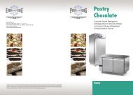
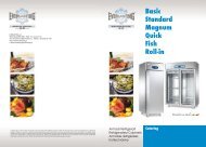
Legenda componenti<br />
UR - Unità remota<br />
VC - Ventilatore condensatore<br />
VE - Ventilatore evaporatore<br />
Legenda colori<br />
Légende des composants<br />
CP - Motocompresseur<br />
HL - Sélecteur humidité<br />
IG - Interrupteur général<br />
IL - Interrupteur lumière<br />
IP - Interrupteur porte<br />
K1 - Relais compresseur<br />
LI - Lumière intérieure<br />
MS - Bornier alimentation<br />
RB - Résistance bac évaportaion<br />
RC - Résistance évacuation<br />
RE - Ballaste<br />
RP - Résistance anti-eau de condensation<br />
RS - Résitance dégivrage<br />
SA - Sonde thermostat<br />
SG - Soupape solénoÏde<br />
SS - Sonde dégivrage<br />
LS - Témoin dégivrage<br />
S - Starter<br />
NE - Nero<br />
GR - Grigio<br />
AR - Arancio<br />
RO - Rosso<br />
MA - Marrone<br />
BL - Blu<br />
BI - Bianco<br />
GV - Giallo-verde<br />
RA - Rosa<br />
VI - Viola<br />
AZ - Azzurro chiaro<br />
UR - Group à distance<br />
VC - Ventilateur condenseur<br />
VE - Ventilateur évaporateur<br />
Légende des couleurs<br />
NE - Noir<br />
GR - Gris<br />
AR - Orange<br />
RO - Rouge<br />
MA - Marron<br />
BL - Bleu<br />
BI - Blanc<br />
GV - Jaune-vert<br />
RA - Rose<br />
VI - Violet<br />
AZ - Bleu clair<br />
12<br />
List of components<br />
CP - Motor compressor<br />
HL - Humidity selector<br />
IG - Main switch<br />
IL - Light switch<br />
IP - Door microswitch<br />
K1 - Compressor relay<br />
LI - Interior light<br />
MS - Power supply terminal board<br />
RB - Condensate collecting tray heater<br />
RC - Drain resistance<br />
RE - Reactor<br />
RP - Anti-condensate resistance<br />
RS - Defrost resistance<br />
SA - Thermostat sensor<br />
SG - Solenoid Valve<br />
SS - Defrost sensor<br />
LS - Defrost warning light<br />
S - Starter<br />
Tabelle Teilebeschreibung<br />
CP - Motorverdichter<br />
HL - Feuchtigkeitswähler<br />
IG - Hauptschalter<br />
IL - Lichtschalter<br />
IP - Türschalter<br />
K1 - Verdichterrelais<br />
LI - Innenlicht<br />
MS - Klemmenleiste Versorgung<br />
RB - Kondenswasserschale Heizung<br />
RC - Ablaßwiderstand<br />
RE - Reaktor<br />
RP - Heizwiderstand<br />
RS - Abtauwiderstand<br />
SA - Temperatursensor<br />
SG - Solenoidventil<br />
SS - Abtausensor<br />
LS - Abtauung Kontrollampe<br />
S - Starter<br />
UR - Remote unit<br />
VC - Condenser fan<br />
VE - Evaporator fan<br />
Colour code<br />
NE - Black<br />
GR - Grey<br />
AR - Orange<br />
RO - Red<br />
MA - Brown<br />
BL - Blue<br />
BI - White<br />
GV - Yellow-Green<br />
RA - Pink<br />
VI - Violet<br />
AZ - Light blue<br />
<strong>ROLL</strong>.02<br />
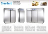
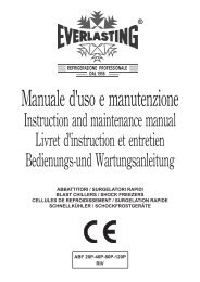
MODELLO Dimensioni Capacità Temp. interna Classe Potenza Assorbimento Gas Peso<br />
MODELE Dimensions Capacity Internal temp. Class Power Absorption Gas Weight<br />
MODEL Dimensions Capacité Temp. Intérieure Classe Puissance Absorption Gaz Poids<br />
MODELL Abmessungen Kapazität Innentemperatur Klasse Leistung Energieverbrauch Kältemittel Gewicht<br />
mm lt °C °C watt watt gas kg<br />
<strong>ROLL</strong>-<strong>IN</strong> 1 TNV 880x994x2200h 1120 +2° +10°C T<br />
+43° C<br />
<strong>ROLL</strong>-TH 1 TNV 880x1081x2200h 1233 +2° +10°C Max<br />
<strong>ROLL</strong>-<strong>IN</strong> 2 TNV 1760x994x2200h 2466 +2° +10°C T<br />
+43° C<br />
<strong>ROLL</strong>-TH 2 TNV 1760x1081x2200h 2700 +2° +10°C Max<br />
Tensione alimentazione - Voltage - Tension d’alimentation - Speisungsspannung 230/1/50<br />
2200<br />
1820<br />
994<br />
880<br />
2200<br />
1820<br />
1081<br />
880<br />
1833 810 R404 A 215<br />
1630 1220 R404 A 292<br />
994 1760 1081 1760<br />
UR - Entfernt installierte Einheit<br />
VC - Verflüssigergebläse<br />
VE - Verdampfergebläse<br />
Tabelle Farben<br />
NE - Schwarz<br />
GR - Grau<br />
AR - Orange<br />
RO - Rot<br />
MA - Braun<br />
BL - Blau<br />
BI - Weiß<br />
GV - Gelb-Grün<br />
RA - Rosarot<br />
VI - Violett<br />
AZ - Hellblau
<strong>ROLL</strong>.02<br />
MA<br />
BL<br />
VI<br />
H L<br />
MA<br />
NE<br />
13<br />
RS<br />
RC<br />
RO<br />
GR<br />
BL<br />
EVKB33
<strong>ROLL</strong>.02<br />
15
EVERLAST<strong>IN</strong>G s.r.l.<br />
46029 SUZZARA (MN) - ITALY - S.S. Cisa km.161<br />
Tel.0376/521800 (4 linee r.a.) - Telefax 0376/521794<br />
http://www.everlasting.it - E-mail:everlasting@everlasting.it