Digital Communication - Bürkert Fluid Control Systems
Digital Communication - Bürkert Fluid Control Systems
Digital Communication - Bürkert Fluid Control Systems

Create successful ePaper yourself
Turn your PDF publications into a flip-book with our unique Google optimized e-Paper software.
Type 8605<br />
<strong>Digital</strong>e Ansteuerelektronik<br />
für Proportionalventile<br />
- <strong>Digital</strong> <strong>Communication</strong><br />
Serial communication (RS 232 / RS 485)<br />
Serielle Kommunikation (RS 232 / RS 485)<br />
<strong>Communication</strong> sérielle (RS 232 / RS 485)<br />
Supplement to Operating Instructions<br />
Ergänzung zur Bedienungsanleitung<br />
Complément aux instructions de service
We reserve the right to make technical changes without notice.<br />
Technische Änderungen vorbehalten!<br />
Sous réserve de modifications techniques.<br />
© 2010 <strong>Bürkert</strong> Werke GmbH<br />
Operating Instructions 1011/00_EU-ML_00809477 / Original DE
Co n t e n t s<br />
Typ 8605<br />
Description of <strong>Communication</strong> with Type 8605<br />
1. Supplementary Operating inStructiOnS ..............................................................................................................4<br />
1.1. Symbols ......................................................................................................................................................................................4<br />
2. general infOrmatiOn................................................................................................................................................................5<br />
2.1. contact addresses................................................................................................................................................................5<br />
2.2. information on the internet...............................................................................................................................................5<br />
2.3. english terms...........................................................................................................................................................................5<br />
3. Serial cOmmunicatiOn.............................................................................................................................................................6<br />
3.1. rS232 connection to pc....................................................................................................................................................6<br />
3.2. rS485 connection to pc....................................................................................................................................................8<br />
3.3. transfer protocol.................................................................................................................................................................10<br />
3.4. telegram..................................................................................................................................................................................11<br />
3.5. commands.............................................................................................................................................................................15<br />
3.6. error messages ...................................................................................................................................................................25<br />
english<br />
3
4<br />
1. SupplemenTary OperaTing<br />
inSTrucTiOnS<br />
Supplementary Operating Instructions<br />
The Supplementary Operating Instructions describe communication with the control electronics for proportional<br />
valves.<br />
Safety Information!<br />
Safety instructions and information for using the device may be found in the corresponding operating instructions.<br />
• The operating instructions must be read and understood.<br />
1.1. Symbols<br />
Danger!<br />
Warns of an immediate danger!<br />
•<br />
Failure to observe the warning may result in a fatal or serious injury.<br />
WarnIng!<br />
Warns of a potentially dangerous situation!<br />
•<br />
Failure to observe the warning may result in serious injuries or death.<br />
CauTIon!<br />
Warns of a possible danger!<br />
•<br />
Failure to observe this warning may result in a moderate or minor injury.<br />
noTe!<br />
Warns of damage to property!<br />
•<br />
Failure to observe the warning may result in damage to the device or the equipment.<br />
Indicates important additional information, tips, and recommendations which are important for your safety<br />
and the flawless functioning of the device.<br />
Refers to information in these operating instructions or in other documentation.<br />
→ designates<br />
a procedure that must be carried out.<br />
english<br />
Typ 8605
General Information<br />
2. general infOrmaTiOn<br />
2.1. contact addresses<br />
germany<br />
Contact address:<br />
<strong>Bürkert</strong> <strong>Fluid</strong> <strong>Control</strong> System<br />
Sales Center<br />
Chr.-<strong>Bürkert</strong>-Str. 13-17<br />
d-74653 Ingelfingen<br />
Phone: 07940 - 10 91 111<br />
Fax: 07940 - 10 91 448<br />
E-mail: info@de.buerkert.com<br />
International<br />
Contact addresses can be found on the final pages of the printed operating instructions.<br />
And also on the Internet at:<br />
www.burkert.com<br />
2.2. information on the internet<br />
The operating instructions and data sheets for device types can be found on the Internet at:<br />
www.burkert.com<br />
Complete documentation is also available on Cd and can be ordered under Id number 804625.<br />
2.3.<br />
Typ 8605<br />
english terms<br />
English technical terms and proper nouns appear just as they were in the original German version (i.e. in English).<br />
The English variables and function names, etc. that were used in the German version are also unchanged in the<br />
English version.<br />
english<br />
5
6<br />
3.<br />
Serial cOmmunicaTiOn<br />
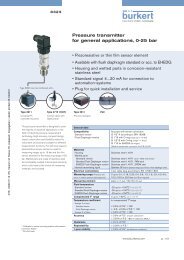
3.1. rS232 connection to pc<br />
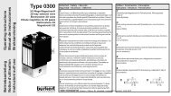
3.1.1. rS232 - module for cable plug<br />
(item number: 667840)<br />
Fig. 1:<br />
Pin assignment<br />
RS232 - Module for cable plug (667840)<br />
3<br />
4 2<br />
type 8605 - rS232 pc (SuB-D 9-pin plug)<br />
RS232 Txd (Pin 1 M8 plug) Pin 2<br />
RS232 Rxd (Pin 3 M8 plug) Pin 3<br />
RS232 GNd (Pin 2 and 4 M8 plug) Pin 5<br />
Table 1:<br />
Pin assignment - module for cable plug - RS232<br />
english<br />
1<br />
5<br />
9<br />
31,8<br />
Typ 8605<br />
Serial <strong>Communication</strong><br />
45
Serial <strong>Communication</strong><br />
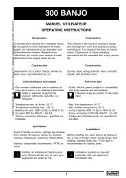
3.1.2. rS232 - module for Din-rail version<br />
(item number: 667842)<br />
7 8 9<br />
Fig. 2: RS232 - Module for DIN-rail version (667842)<br />
Assignment of screw-type terminals<br />
type 8605 - rS232 pc (SuB-D 9-pin plug)<br />
RS232 Txd (terminal 7) Pin 2<br />
RS232 Rxd (terminal 8) Pin 3<br />
RS232 GNd (terminal 9) Pin 5<br />
Table 2:<br />
Typ 8605<br />
Assignment of screw-type terminals - Module for DIN-rail version - RS232<br />
31,5<br />
22,4<br />
english<br />
4<br />
7
8<br />
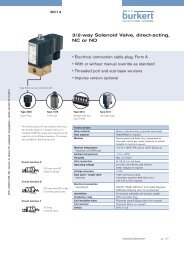
3.2. rS485 connection to pc<br />
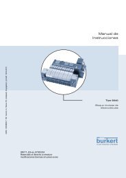
3.2.1. rS485 - module for cable plug<br />
(item number: 667841)<br />
Fig. 3:<br />
Pin assignment<br />
RS485 - Module for cable plug (667841)<br />
type 8605 - rS485<br />
3<br />
4 2<br />
RS485 Rxd / Txd-N A cable (Pin 3 M8 plug)<br />
RS485 Rxd / Txd-P B cable (Pin 1 M8 plug)<br />
RS485 GNd (Pin 2 and 4 M8 plug)<br />
Table 3:<br />
Pin assignment - RS485<br />
1<br />
5<br />
9<br />
31,8<br />
Serial <strong>Communication</strong><br />
Operation with terminating resistors (last subscriber):<br />
The terminating resistors can be connected/disconnected with the dIP switches on the communication module.<br />
Fig. 4:<br />
dIP switches<br />
RS485 - Position of the DIP switches<br />
english<br />
Typ 8605<br />
45
Serial <strong>Communication</strong><br />
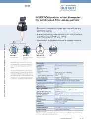
3.2.2. rS485<br />
- module for Din-rail version<br />
(item number: 667843)<br />
7 8 9<br />
Fig. 5: RS485<br />
- Module for DIN-rail version (667843)<br />
Assignment of screw-type terminals<br />
type 8605 - rS 485<br />
RS485 Rxd / Txd-N A-Leitung (Klemme 8)<br />
RS485 Rxd / Txd-P B-Leitung (Klemme 7)<br />
RS485 GNd (Klemme 9)<br />
Table 4:<br />
Typ 8605<br />
Assignment of screw-type terminals - Module for DIN-rail version - RS485<br />
Operation with terminating resistors (last subscriber):<br />
The terminating resistors can be connected/disconnected with the dIP switches on the communication module.<br />
31,5<br />
22,4<br />
english<br />
6,2<br />
9
10<br />
3.3.<br />
3.3.1.<br />
Transfer protocol<br />
Transfer channels<br />
The following lines are used for the serial interface:<br />
Wire-conducted communication<br />
GNd Ground<br />
Rxd Reception line (PC → device)<br />
Txd Transmission line (device → PC)<br />
3.3.2.<br />
Data format<br />
The layout of the serial interface protocol is as follows:<br />
Transfer rate 9600 Bd<br />
data bits 8<br />
Parity None<br />
Stop bits 1<br />
Hardware handshake No<br />
english<br />
Typ 8605<br />
Serial <strong>Communication</strong>
3.4.<br />
3.4.1.<br />
Serial <strong>Communication</strong><br />
Telegram<br />
general information<br />
The layout of the transmission telegram is based on the HART protocol. HART is a master slave protocol, i.e.<br />
each transmission is started by a master device (PC or manual operating unit). The slave device (field device, 8605)<br />
responds only to a master telegram if the device was addressed by the telegram.<br />
Exception: Burst message<br />
Additional information about the HART protocol may be found under:<br />
http://www.hartcomm.org/<br />
A distinction is drawn between short frame and long frame telegrams. They consist of the following characters:<br />
Short frame<br />
Preamble 2 ... 20 Bytes 0xFF (differs from HART: 5...20 bytes)<br />
hex<br />
delimiter 1 byte<br />
Master → Slave 0x02hex Slave → Master 0x06hex Burst message 0x01hex Address 1 byte (Master address + Burst info + Polling address)<br />
Command 1 byte<br />
Byte count 1 byte<br />
Status 2 bytes, only for slave → master<br />
data 0 ... 255 (... 255 (-2)) bytes<br />
Checksum 1 byte<br />
long frame<br />
Typ 8605<br />
Preamble 2 ... 20 bytes 0xFF (differs from HART: 5...20 bytes)<br />
hex<br />
delimiter 1 byte<br />
Master → Slave 0x82hex Slave → Master 0x86hex Burst message 0x81hex Address 5 bytes<br />
Command 1 bytes<br />
Byte count 1 byte<br />
Status 2 bytes, only for slave → Master<br />
data 0 ... 255 bytes<br />
Checksum 1 byte<br />
english<br />
11
12<br />
3.4.2.<br />
preamble<br />
The preamble consists of 2 to 20 0xFF characters. It is used to synchronize the data transfer.<br />
3.4.3.<br />
Delimiter<br />
Telegrams are distinguished from each other mainly by the delimiter:<br />
message type Short frame long frame<br />
Master → Slave 0x02 0x82<br />
Slave → Master 0x06 0x86<br />
Burst message from slave 0x01 0x81<br />
Master: PC or manual operating unit<br />
Slave: Field device, 8605<br />
3.4.4.<br />
address<br />
Serial <strong>Communication</strong><br />
The address field contains both the master address and the slave address of the message. One byte is used for this<br />
purpose in a short frame, while 5 bytes are used in a long frame. Each device must respond to a long frame address<br />
of 0 (= broadcast address), i.e. bit 0 and bit 1 = 1 or 0, bits 2 ... 39 = 0.<br />
The highest-order bit in both formats indicates which master is involved in communication.<br />
(1: Primary master, continuously connected hosts;<br />
0: Secondary master, manual operating units)<br />
Short frame adresse (1 byte)<br />
Bit 0 (MBS) Master Address (m)<br />
0: Secondary Master<br />
1: Primary Master<br />
Bit 1 Burst Info (b)<br />
0: Not in burst mode<br />
1: In burst mode<br />
Bit 2 ... 7 (LBS) Polling Address (x) (0 ... 32), bit 4 = MSB, bit 7 = LSB<br />
mbxxxxxx<br />
Fig. 6:<br />
Short Frame Adresse<br />
english<br />
x: Polling Address<br />
b: Burst Info<br />
m: Master Address<br />
Typ 8605
Serial <strong>Communication</strong><br />
long frame address (5 bytes)<br />
Bit 0 (MSB) Master Address (m)<br />
0: Secondary Master<br />
1: Primary Master<br />
Bit 1 Burst Info (b)<br />
0: Not in burst mode<br />
1: In burst mode<br />
Bit 2 ... 7 Manufacturer Id Code (x) (Bit 2 = MSB, Bit 7 = LSB)<br />
0x78 = Burkert<br />
hex<br />
Bit 8 ... 15 device Type Code (y) (Bit 8 = MSB, Bit 15 = LSB)<br />
0xEB = 8605<br />
hex<br />
Bit 16 ... 39 (LBS) device Id Number (z) (Bit 16 = MSB, Bit 39 = LSB),<br />
(corresponds to the address, results from an XOR link between identification number and<br />
serial number of the device)<br />
Each field device must reply to address 0 (bit 2 … 39 = 0) (broadcast telegram)<br />
Byte 4<br />
mbxxxxxx<br />
Fig. 7:<br />
3.4.5.<br />
Byte 4<br />
yyyyyyyy<br />
Byte 4<br />
zzzzzzzz<br />
Long Frame Adresse<br />
command<br />
Byte 4<br />
zzzzzzzz<br />
Byte 4<br />
zzzzzzzz<br />
z: device Id Number<br />
y: device Type Code<br />
x: Manufacturer Id Code<br />
b: Burst Info<br />
m: Master Address<br />
Commands are divided into the following categories in conformity with HART:<br />
Universal commands Commands 0 ... 30<br />
Standard commands Commands 32 ... 126 (123 ... 126 not public)<br />
device-specific command Commands 128 ... 253<br />
(reserved: 31, 127, 254, 255)<br />
3.4.6.<br />
Typ 8605<br />
Byte count<br />
The byte count indicates how many more bytes come before the checksum, i.e. the number of status bytes +<br />
number of data bytes. This results in a maximum total number of 255 status and data bytes.<br />
english<br />
13
14<br />
3.4.7.<br />
Status<br />
Serial <strong>Communication</strong><br />
Transferred only from the slave to the master in a response telegram. Consists of 2 bytes. The status bytes are<br />
used to detect communication errors or for the operating status of the slave device.<br />
3.4.8.<br />
Data<br />
data bytes, depending on the command. A maximum of 255 data bytes can be transferred. Ensure that the total<br />
number of bytes of address + data cannot exceed 255.<br />
3.4.9.<br />
checksum<br />
The checksum is an XOR (exclusive OR, anticoincidence) combination of all bytes from the starting byte (delimiter)<br />
up to and including the last data byte.<br />
An XOR combination is the logical combination function of two logical values ("0" and "1"). It yields a result of "1"<br />
if one but not both of the two values is "1".<br />
Table 5:<br />
XOR combination<br />
a B y = a XOr B<br />
0 0 0<br />
0 1 1<br />
1 0 1<br />
1 1 0<br />
english<br />
Typ 8605
Serial <strong>Communication</strong><br />
3.5. commands<br />
command number<br />
0x00<br />
command name<br />
request<br />
readuniqueldentifier<br />
Command 0x00<br />
Byte count 0<br />
data -<br />
response<br />
Command 0x00<br />
Byte count 14 (18)<br />
Status 2 bytes, device status<br />
data 12 (16) bytes<br />
0 "254" (expansion)<br />
1 manufacturer identification code<br />
2 manufacturer‘s device type code<br />
3 number of preambles required<br />
4 universal command revision<br />
5 device-specific command revision<br />
6 software revision<br />
7 hardware revision<br />
8 device function flags<br />
9 ... 11 device Id number 1)<br />
(12 common-practice command revision) 1)<br />
(13 common tables revision) 2)<br />
(14 data link revision) 2)<br />
(15 device family code) 2)<br />
Description<br />
HART-Universal Command 0.<br />
Table 6:<br />
Command 0x00 - ReadUniqueldentifier<br />
1) First byte transferred: MSB<br />
2) Reserved for later versions<br />
Typ 8605<br />
english<br />
15
16<br />
command number<br />
0x01<br />
command name<br />
request<br />
readprimaryVariable<br />
Command 0x01<br />
Byte count 0<br />
data -<br />
response<br />
Command 0x01<br />
Byte count 7<br />
Status 2 bytes, device status<br />
data 5 bytes<br />
0 PV units code<br />
1 ... 4 primary variable (float) 3)<br />
Description<br />
HART-Universal Command 1.<br />
PV Unit 0 x 39 %<br />
hex<br />
PV Coil current scaled as a %, where I LO = 0 % and I HI = 100 %<br />
(see also "3.6.3. Codings and units")<br />
Table 7:<br />
Command 0x01 - ReadPrimaryVariable<br />
Example:<br />
All data as hexadecimal numbers (prefix 0x) short frame<br />
Primary master<br />
Short address 0<br />
data sent<br />
data received<br />
• Read Primary Variable<br />
0xFF 0xFF 0x02 0x80 0x01 0x00 0x83<br />
0xFF 0xFF 0x06 0x80 0x01 0x07 0x00 0x00 0x39 0x41 0xC8 0x00 0x00 0x30<br />
3)<br />
0x39 for PV Unit = %<br />
0x41C80000 = 25.0 IEEE 754 floating point<br />
First byte transferred: MSB<br />
english<br />
Typ 8605<br />
Serial <strong>Communication</strong>
Serial <strong>Communication</strong><br />
command number<br />
0x02<br />
command name<br />
request<br />
readcurrentandpercentOfrange<br />
Command 0x02<br />
Byte count 0<br />
data -<br />
response<br />
Command 0x02<br />
Byte count 10<br />
Status 2 bytes, device status<br />
data 8 bytes<br />
0 ... 3 current (mA) (float) 4)<br />
4 ... 7 percent of range (float) 4)<br />
Description<br />
HART-Universal Command 2.<br />
current: Coil current (mA)<br />
percent of range: Coil current scaled as a %, where I = 0 % and I = 100 %<br />
LO HI<br />
(see also „3.6.3. Codings and units“)<br />
Table 8: Command 0x02 - ReadCurrentAndPercentOfRange<br />
4)<br />
First byte transferred: MSB<br />
Typ 8605<br />
english<br />
17
18<br />
command number<br />
0x03<br />
command name<br />
request<br />
readcurrentandfourDynamicVariables<br />
Command 0x03<br />
Byte count 0<br />
data -<br />
response<br />
Command 0x03<br />
Byte count 26<br />
Status 2 bytes, device status<br />
data 24 bytes<br />
0 ... 3 current (mA) (float) 5)<br />
4 PV units code<br />
5 ... 8 primary variable (float) 5)<br />
9 SV units code<br />
10 ... 13 secondary variable (float) 5)<br />
14 TV units code<br />
15 ... 18 third variable (float) 5)<br />
19 FV units code<br />
20 ... 23 fourth variable (float) 5)<br />
Description<br />
HART-Universal Command 3.<br />
current Coil current / PV in mA<br />
PV Unit 0x39 „%“<br />
hex<br />
PV Coil current Process Value PV in %, where I = 0 % and I = 100 %<br />
LO HI<br />
SV Unit 0x39 „%“<br />
hex<br />
SV Setpoint SP in %, where I = 0 % and I = 100 %<br />
LO HI<br />
TV Unit 0x39 „%“ hex 6)<br />
TV <strong>Control</strong>led Variable CV<br />
FV Unit 0x33 „sec“ hex 6)<br />
FV Operating time of the device since it was last switched on or reset<br />
(see also „3.6.3. Codings and units“)<br />
Table 9:<br />
Command 0x03 - ReadCurrentAndFourDynamicVariables<br />
5) First byte transferred: MSB<br />
6) As of firmware version A.04.00.01, before it 0xFBhex none<br />
english<br />
Typ 8605<br />
Serial <strong>Communication</strong>
Serial <strong>Communication</strong><br />
command number<br />
0x06<br />
command name<br />
request<br />
Writepollingaddress<br />
Command 0x06<br />
Byte count 1<br />
data 1 byte<br />
0 polling address<br />
response<br />
Command 0x06<br />
Byte count 3<br />
Status 2 bytes, device status<br />
data 1 byte<br />
0 polling address<br />
Description<br />
HART-Universal Command 6:<br />
Command for changing the HART polling address.<br />
Table 10:<br />
Typ 8605<br />
Command 0x06 - WritePollingAddress<br />
english<br />
19
20<br />
command number<br />
0x27<br />
command name<br />
request<br />
eepromcontrol<br />
Command 0x27<br />
Byte count 1<br />
data 1 byte<br />
0 = Write to EEPROM<br />
1 = Copy content of EEPROM to RAM<br />
response<br />
Command 0x27<br />
Byte count 3<br />
Status 2 bytes, device status<br />
data 1 byte<br />
0 = Write to EEPROM<br />
1 = Copy content of EEPROM to RAM<br />
Description<br />
HART-Universal Command 39.<br />
Command to write/read parameters (for example the polling address) to/from EEPROM.<br />
Table 11:<br />
Command 0x27 - Eeprom<strong>Control</strong><br />
english<br />
Typ 8605<br />
Serial <strong>Communication</strong>
Serial <strong>Communication</strong><br />
command number<br />
0x80<br />
command name<br />
request<br />
readVersion<br />
Command 0x80<br />
Byte count 0<br />
data<br />
response<br />
-<br />
Command 0x80<br />
Byte count 36<br />
Status 2 bytes, device status<br />
data 34 bytes<br />
0...1 device type (unsigned int), e.g. 8605<br />
2 device number, z. B. 1<br />
3...6 device Id number (unsigned long) 7)<br />
7...10 device serial number (unsigned long) 7)<br />
11...14 Software Id number (unsigned long) 7)<br />
15 Software version x (x.y.z.cc): A ... Z<br />
16 Software version y (x.y.z.cc): 0 ... 99<br />
17 Software version z (x.y.z.cc): 0 ... 99<br />
18 Software version cc (x.y.z.cc): 0 ... 99<br />
19 EEPROM layout version x (x.y): A ... Z<br />
20 EEPROM layout version y (x.y): 0 ... 99<br />
21 Table_x version (x.y): A ... Z<br />
22 Table_y version (x.y): 0 ... 99<br />
23 ... 26 Bios Id number (unsigned long)<br />
27 Bios version x (x.y.z.cc): A ... Z<br />
28 Bios version y (x.y.z.cc): 0 ... 99<br />
29 Bios version z (x.y.z.cc): 0 ... 99<br />
30 Bios version cc (x.y.z.cc): 0 ... 99<br />
31 MFi software version x (x.y): A ... Z<br />
32 MFi software version y (x.y): 0 ... 99<br />
33 MFi software version x (x.y): A ... Z<br />
Description<br />
Command to read device information and the software version.<br />
Table 12:<br />
7)<br />
Command 0x80 - ReadVersion<br />
First byte transferred: LSB<br />
Typ 8605<br />
english<br />
21
22<br />
command number<br />
0x92<br />
command name<br />
request<br />
extSetpoint<br />
Command 0x92<br />
Byte count 5<br />
data 1 byte<br />
0 Internal set-point value settings<br />
1<br />
4 bytes<br />
External set-point value settings<br />
0 ... 3 Set-point value [%] (float) 8)<br />
response<br />
Command 0x92<br />
Byte count 7<br />
Status 2 bytes, device status<br />
Serial <strong>Communication</strong><br />
data 1 byte<br />
0 Internal set-point value settings<br />
1 External set-point value settings<br />
4 bytes<br />
0 ... 3 Set-point value [%] (float) 8)<br />
Description<br />
determines the set-point value settings and describes the external set-point value as a percentage:<br />
Internal = analog - the set-point value settings is assigned by the analog set-point value signal that is<br />
created<br />
External = RS232, RS485<br />
Table 13:<br />
8)<br />
Command 0x92 - ExtSetpoint<br />
First byte transferred: MSB<br />
english<br />
Typ 8605
Example:<br />
Typ 8605<br />
Serial <strong>Communication</strong><br />
All data as hexadecimal numbers (prefix 0x) short frame<br />
Primary master<br />
Short address 0<br />
data sent<br />
data received<br />
• Set-point value settings digital 0.0% ( 0x00000000 IEEE 754)<br />
0xFF 0xFF 0x02 0x80 0x92 0x05 0x01 0x00 0x00 0x00 0x00 0x14<br />
0xFF 0xFF 0x06 0x80 0x92 0x07 0x00 0x00 0x01 0x00 0x00 0x00 0x00 0x12<br />
• Set-point value settings digital 50.0% ( 0x42480000 IEEE 754)<br />
0xFF 0xFF 0x02 0x80 0x92 0x05 0x01 0x42 0x48 0x00 0x00 0x1E<br />
0xFF 0xFF 0x06 0x80 0x92 0x07 0x00 0x00 0x01 0x42 0x48 0x00 0x00 0x18<br />
• Set-point value settings digital 100.0% ( 0x42C80000 IEEE 754)<br />
0xFF 0xFF 0x02 0x80 0x92 0x05 0x01 0x42 0xC8 0x00 0x00 0x9E<br />
0xFF 0xFF 0x06 0x80 0x92 0x07 0x00 0x00 0x01 0x42 0xC8 0x00 0x00 0x98<br />
• Switch set-point value settings to analog set-point value settings:<br />
0xFF 0xFF 0x02 0x80 0x92 0x05 0x00 0x00 0x00 0x00 0x00 0x15<br />
0xFF 0xFF 0x06 0x80 0x92 0x07 0x00 0x00 0x00<br />
english<br />
23
24<br />
command number<br />
command name<br />
Device types<br />
request<br />
0xee<br />
Command 0x92<br />
Byte count 5<br />
0x98<br />
extSetpointWithoutanswer<br />
data 1 byte<br />
0 Set-point value settings, internal<br />
1<br />
4 bytes<br />
Set-point value settings, external<br />
1 ... 4 Set-point value [%] (float) 9)<br />
response<br />
Command -<br />
Byte count -<br />
Status -<br />
Serial <strong>Communication</strong><br />
data -<br />
Description<br />
determines the set-point value settings and describes the external set-point value as a percentage:<br />
Internal = analog - the set-point value settings is assigned by the analog<br />
set-point value signal that is created<br />
External = RS232, RS485<br />
No response is sent for this command.<br />
Table 14:<br />
9)<br />
Command 0x98 - ExtSetpointWithoutAnswer<br />
First byte transferred: MSB<br />
english<br />
Typ 8605
Serial <strong>Communication</strong><br />
3.6. error messages<br />
3.6.1. first status byte<br />
communication error<br />
Error code 0x82<br />
Error name overflow<br />
description UART error, receive buffer, overflow was detected.<br />
Error code 0x88<br />
Error name checksum<br />
description An incorrect checksum was received.<br />
Error code 0x90<br />
Error name framing<br />
description UART error, framing error was detected.<br />
Error code 0xa0<br />
Error name overrun<br />
description UART error, overrun error was detected.<br />
Error code 0xc0<br />
Error name parity<br />
description UART error, parity error was detected.<br />
Table 15:<br />
Typ 8605<br />
Error messages - First status byte - <strong>Communication</strong> error<br />
english<br />
25
26<br />
command error<br />
Error code 0x02<br />
Error name invalid_selection<br />
description An invalid data range was selected.<br />
Error code 0x03<br />
Error name parameter_too_large<br />
description<br />
Serial <strong>Communication</strong><br />
Transfer parameter too large. It may be a table or array index from the data range, i.e. an<br />
incorrect value range.<br />
Error code 0x04<br />
Error name parameter_too_small<br />
description<br />
Transfer parameter too small. It may be a table or array index from the data range, i.e. too low<br />
for the value range.<br />
Error code 0x05<br />
Error name too_few_data_bytes<br />
description Not enough data bytes were received.<br />
Error code 0x07<br />
Error name write_protected<br />
description device is write-protected.<br />
Error code 0x10<br />
Error name access_restricted<br />
The command that was sent cannot be executed (currently). Access was denied. The cause<br />
description could be, for example, that the necessary access rights are lacking or the command is not<br />
permitted in the current operating mode.<br />
Error code 0x40<br />
Error name no_command<br />
description<br />
Invalid/incorrect command, i.e. the command that was received is not supported by the<br />
device.<br />
Table 16:<br />
Error messages - First status byte - Command error<br />
english<br />
Typ 8605
Serial <strong>Communication</strong><br />
Device status<br />
Error code 0x20<br />
Error name device_busy<br />
description device is busy.<br />
Table 17:<br />
Error messages - First status byte - Device status<br />
internal device-specific error messages<br />
Error code 0x01<br />
Error name timeout<br />
description<br />
The time limit was exceeded, i.e. too much time passed between a valid received delimiter<br />
and a complete command.<br />
Error code 0x41<br />
Error name wrong_command<br />
description<br />
Incorrect command structure, i.e. the command is valid and exists, but the number of bytes<br />
transferred does not match. Only 1 byte was transferred for a 2-byte variable.<br />
Table 18:<br />
Typ 8605<br />
Error messages - First status byte - Internal device-specific error messages<br />
english<br />
27
28<br />
3.6.2. Second status byte<br />
Second status byte<br />
Bit 7 Field device malfunction<br />
Bit 6 reserved for future purposes<br />
Bit 5 reserved for future purposes<br />
Bit 4 reserved for future purposes<br />
Bit 3 reserved for future purposes<br />
Bit 2 reserved for future purposes<br />
Bit 1 reserved for future purposes<br />
Bit 0 reserved for future purposes<br />
Table 19:<br />
Error messages - Second status byte<br />
UART errors take precedence in error detection.<br />
Multiple UART errors cannot be detected simultaneously.<br />
3.6.3. codings and units<br />
manufacturer coding (Hart standard)<br />
Hex Dec Description<br />
0x78 120 Buerkert<br />
0xFA 250 not used<br />
0x FB 251 none<br />
0xFC 252 unknown<br />
0xFd 253 special<br />
Table 20:<br />
Codings<br />
units (Hart standard)<br />
Hex Dec unit Description<br />
0x33 51 sec Seconds<br />
0x39 57 % Percent<br />
0xFA 250 - not used<br />
0xFB 251 - none<br />
0xFC 252 - unknown<br />
0xFd 253 - special<br />
Table 21:<br />
Units<br />
english<br />
Typ 8605<br />
Serial <strong>Communication</strong>
In h a lt<br />
Typ 8605<br />
Beschreibung der Kommunikation mit Typ 8605<br />
1. ergänzenDe BeDienungSanleitung.........................................................................................................................28<br />
1.1. Darstellungsmittel ..............................................................................................................................................................28<br />
2. allgemeine HinWeiSe ..............................................................................................................................................................29<br />
2.1. Kontaktadressen.................................................................................................................................................................29<br />
2.2. informationen im internet...............................................................................................................................................29<br />
2.3. englische Begriffe..............................................................................................................................................................29<br />
3. Serielle KOmmuniKatiOn.....................................................................................................................................................30<br />
3.1. rS 232 Verbindung zum pc .........................................................................................................................................30<br />
3.2. rS 485 Verbindung zum pc .........................................................................................................................................32<br />
3.3. Übertragungsprotokoll.....................................................................................................................................................34<br />
3.4. telegramm..............................................................................................................................................................................35<br />
3.5. Befehle .....................................................................................................................................................................................39<br />
3.6. fehlermeldungen................................................................................................................................................................49<br />
deutsch<br />
27
28<br />
Ergänzende Bedienungsanleitung<br />
1. ergänzenDe BeDienungSanleiTung<br />
die ergänzende Bedienungsanleitung beschreibt die Kommunikation mit der Ansteuerelektronik für<br />
Proportionalventile.<br />
Informationen zur Sicherheit!<br />
Sicherheitshinweise und Informationen für den Einsatz des Gerätes finden Sie in der dazugehörigen<br />
Bedienungsanleitung.<br />
•<br />
die Bedienungsanleitung muss gelesen und verstanden werden.<br />
1.1. Darstellungsmittel<br />
gefahr!<br />
Warnt vor einer unmittelbaren gefahr!<br />
•<br />
Bei Nichtbeachtung sind Tod oder schwere Verletzungen die Folge.<br />
Warnung!<br />
Warnt vor einer möglicherweise gefährlichen Situation!<br />
•<br />
Bei Nichtbeachtung drohen schwere Verletzungen oder Tod.<br />
VorSIChT!<br />
Warnt vor einer möglichen gefährdung!<br />
•<br />
Nichtbeachtung kann mittelschwere oder leichte Verletzungen zur Folge haben.<br />
hInWeIS!<br />
Warnt vor Sachschäden!<br />
•<br />
Bei Nichtbeachtung kann das Gerät oder die Anlage beschädigt werden.<br />
Bezeichnet wichtige Zusatzinformationen, Tipps und Empfehlungen.<br />
Verweist auf Informationen in dieser Bedienungsanleitung oder in anderen dokumentationen.<br />
→ Markiert<br />
einen Arbeitsschritt, den Sie ausführen müssen.<br />
deutsch<br />
Typ 8605
Allgemeine Hinweise<br />
2. allgemeine HinweiSe<br />
2.1. Kontaktadressen<br />
Deutschland<br />
Kontaktadresse:<br />
<strong>Bürkert</strong> <strong>Fluid</strong> <strong>Control</strong> System<br />
Sales Center<br />
Chr.-<strong>Bürkert</strong>-Str. 13-17<br />
d-74653 Ingelfingen<br />
Tel. : 07940 - 10 91 111<br />
Fax: 07940 - 10 91 448<br />
E-mail: info@de.buerkert.com<br />
International<br />
die Kontaktadressen finden Sie auf den letzten Seiten der gedruckten Bedienungsanleitung.<br />
Außerdem im Internet unter:<br />
www.burkert.com<br />
2.2. informationen im internet<br />
Bedienungsanleitungen und datenblätter zu Typ 8605 finden Sie im Internet unter:<br />
www.buerkert.de<br />
desweiteren steht eine komplette dokumentation auf Cd bereit, die unter der Identnummer 804625 bestellt<br />
werden kann.<br />
2.3.<br />
Typ 8605<br />
englische Begriffe<br />
Auf eine Übersetzung von englischen Fachbegriffen und Eigennamen wird verzichtet. Weiterhin werden die verwendeten<br />
Variablen, Funktionsnamen usw. im Englischen belassen und wie deutsche Begriffe verwendet.<br />
deutsch<br />
29
30<br />
3.<br />
3.1.<br />
Serielle KOmmuniKaTiOn<br />
rS 232 Verbindung zum pc<br />
3.1.1. rS232 - modul für gerätesteckdose<br />
(Bestellnummer: 667840)<br />
Bild 1:<br />
Anschlussbelegung<br />
RS232 - Modul für Gerätesteckdose (667840)<br />
3<br />
4 2<br />
typ 8605 - rS 232 pc (SuB-D 9pin Stecker)<br />
RS232 Txd (Pin 1 M8 Stecker) Pin 2<br />
RS232 Rxd (Pin 3 M8 Stecker) Pin 3<br />
RS232 GNd (Pin 2 und 4 M8 Stecker) Pin 5<br />
Tabelle 1:<br />
Anschlussbelegung - Modul für Gerätesteckdose RS 232<br />
deutsch<br />
1<br />
5<br />
9<br />
31,8<br />
Typ 8605<br />
Serielle Kommunikation<br />
45
Serielle Kommunikation<br />
3.1.2. rS232 - modul für Hutschienenausführung<br />
(Bestellnummer: 667842)<br />
7 8 9<br />
Bild 2: RS232 - Modul für Hutschienenausführung (667842)<br />
Anschlussbelegung<br />
typ 8605 - rS 232 pc (SuB-D 9pin Stecker)<br />
RS232 Txd (Klemme 7) Pin 2<br />
RS232 Rxd (Klemme 8) Pin 3<br />
RS232 GNd (Klemme 9) Pin 5<br />
Tabelle 2:<br />
Typ 8605<br />
31,5<br />
Anschlussbelegung Modul für Hutschienenausführung RS 232<br />
deutsch<br />
22,4<br />
4<br />
31
32<br />
3.2.<br />
rS 485 Verbindung zum pc<br />
3.2.1. rS485 - modul für gerätesteckdose<br />
(Bestellnummer: 667841)<br />
Bild 3:<br />
Anschlussbelegung<br />
3<br />
4 2<br />
RS485 - Modul für Gerätesteckdose (667841)<br />
typ 8605 - rS 485<br />
RS485 Rxd / Txd-N A-Leitung (Pin 3 M8 Stecker)<br />
RS485 Rxd / Txd-P B-Leitung (Pin 1 M8 Stecker)<br />
RS485 GNd (Pin 2 und 4 M8 Stecker)<br />
Tabelle 3:<br />
Anschlussbelegung RS 485<br />
1<br />
5<br />
9<br />
31,8<br />
Serielle Kommunikation<br />
Betrieb mit Abschlusswiderständen (letzter Teilnehmer):<br />
die Abschlusswiderstände können mit den dIP-Schaltern auf dem Kommunikationsmodul zu/abgeschaltet<br />
werden.<br />
Bild 4:<br />
dIP-Schalter<br />
RS485 - Position der DIP-Schalter<br />
deutsch<br />
Typ 8605<br />
45
Serielle Kommunikation<br />
3.2.2. rS485<br />
- modul für Hutschienenausführung<br />
(Bestellnummer: 667843)<br />
7 8 9<br />
Bild 5: RS485<br />
- Modul für Hutschienenausführung (667843)<br />
Anschlussbelegung<br />
typ 8605 - rS 485<br />
RS485 Rxd / Txd-N A-Leitung (Klemme 8)<br />
RS485 Rxd / Txd-P B-Leitung (Klemme 7)<br />
RS485 GNd (Klemme 9)<br />
Tabelle 4:<br />
Typ 8605<br />
Anschlussbelegung RS 485<br />
Betrieb mit Abschlusswiderständen (letzter Teilnehmer):<br />
die Abschlusswiderstände können mit den dIP-Schalter auf dem Kommunikationsmodul zu-/abgeschaltet<br />
werden.<br />
31,5<br />
deutsch<br />
22,4<br />
6,2<br />
33
34<br />
3.3.<br />
3.3.1.<br />
Übertragungsprotokoll<br />
Übertragungskanäle<br />
Für die serielle Schnittstelle werden folgende Leitungen verwendet:<br />
drahtgebundene Kommunikation<br />
GNd Masse<br />
Rxd Empfangsleitung (PC → Gerät)<br />
Txd Sendeleitung (Gerät → PC)<br />
3.3.2.<br />
Datenformat<br />
das Protokoll der seriellen Schnittstelle ist wie folgt aufgebaut:<br />
Übertragungsrate 9600 Bd<br />
datenbits 8<br />
Parität none<br />
Stoppbits 1<br />
Hardware-Handshake nein<br />
deutsch<br />
Typ 8605<br />
Serielle Kommunikation
3.4.<br />
3.4.1.<br />
Serielle Kommunikation<br />
Telegramm<br />
allgemeines<br />
der Aufbau des Sendetelegramms beruht auf dem HART-Protokoll. HART ist ein Master-Slave-Protokoll,<br />
d. h. jede Übertragung wird durch ein Master-Gerät gestartet (PC oder manuelle Bedieneinheit). das<br />
Slave-Gerät (Feldgerät, 8605) reagiert nur auf ein Master-Telegramm, wenn es von ihm adressiert wurde.<br />
Ausnahme: Burst message (Burstmeldung).<br />
Weitere Informationen über das HART-Protokoll sind zu finden unter:<br />
http://www.hartcomm.org/<br />
Es wird unterschieden zwischen Short Frame und Long Frame Telegrammen. diese bestehen aus den folgenden<br />
Zeichen:<br />
Short frame<br />
Preamble (Präambel) 2 ... 20 Bytes 0xFF hex (abweichend von HART: 5...20 Bytes)<br />
delimiter (Startzeichen) 1 Byte<br />
Master → Slave 0x02 hex<br />
Slave → Master 0x06 hex<br />
Burstmeldung 0x01hex Address (Adresse) 1 Byte (Master-Adresse + Burst-Info + Polling-Adresse)<br />
Command (Befehl) 1 Byte<br />
Byte count (Bytezählwert) 1 Byte<br />
Status 2 Byte, nur für Slave → Master<br />
data (daten) 0 ... 255 (... 255 (-2)) Bytes<br />
Checksum (Checksumme) 1 Byte<br />
long frame<br />
Typ 8605<br />
Preamble (Präambel) 2 ... 20 Bytes 0xFF hex (abweichend von HART: 5...20 Bytes)<br />
delimiter (Startzeichen) 1 Byte<br />
Master → Slave 0x82 hex<br />
Slave → Master 0x86 hex<br />
Burstmeldung 0x81hex Address (Adresse) 5 Bytes<br />
Command (Befehl) 1 Bytes<br />
Bytecount (Bytezählwert) 1 Byte<br />
Status 2 Byte, nur für Slave → Master<br />
data (daten) 0 ... 255 Bytes<br />
Checksum (Checksumme) 1 Byte<br />
deutsch<br />
35
36<br />
3.4.2.<br />
präambel<br />
Serielle Kommunikation<br />
die Präambel besteht aus 2 bis 20 0xFF Zeichen. Sie wird zum Synchronisieren des datentransfers verwendet.<br />
3.4.3.<br />
Startzeichen<br />
die Telegramme unterscheiden sich in erster Linie durch das Startzeichen (delimiter):<br />
message type (meldungstyp) Short frame long frame<br />
Master → Slave 0x02 0x82<br />
Slave → Master 0x06 0x86<br />
Burst message from Slave<br />
(Burstmeldung vom Slave)<br />
0x01 0x81<br />
Master: PC oder manuelle Bedieneinheit<br />
Slave: Feldgerät, 8605<br />
3.4.4.<br />
adresse<br />
das Adressfeld enthält sowohl die Master Address (Masteradresse), wie auch die Slave Address (Slaveadresse)<br />
der Meldung. In einem Short Frame wird ein Byte dafür verwendet und 5 Bytes in einem Long Frame. Jedes Gerät<br />
muss auf eine Long Frame-Adresse von 0 (= Rundrufadresse (Broadcast Adress)) antworten, d. h. Bit 0 und Bit 1<br />
= 1 oder 0, Bit 2 ... 39 = 0.<br />
In beiden Formaten zeigt das höchste Wertbit an, welcher Master an der Kommunikation beteiligt ist.<br />
(1: Primary Master (Primärer Master), ständig angeschlossene Hosts;<br />
0: Secondary Master (Sekundärer Master), manuelle Betriebseinheiten)<br />
Short frame adresse (1 Byte)<br />
Bit 0 (MBS) Master Address (m)<br />
0: Secondary Master (Sekundärer Master)<br />
1: Primary Master (Primärer Master)<br />
Bit 1 Burst Info (b)<br />
0: Not in burst mode (Nicht im Burstmodus)<br />
1: In burst mode (Im Burstmodus)<br />
Bit 2 ... 7 (LBS) Polling Address (Polling-Adresse) (x) (0 ... 32), Bit 4 = MSB, Bit 7 = LSB<br />
mbxxxxxx<br />
Bild 6:<br />
Short Frame Adresse<br />
deutsch<br />
Typ 8605<br />
x: Polling Address (Polling-Adresse)<br />
b: Burst Info<br />
m: Master Address (Master Adresse)
Serielle Kommunikation<br />
long frame-adresse (5 Byte)<br />
Bit 0 (MSB) Master Adresse (m)<br />
0: Secondary Master (Sekundärer Master)<br />
1: Primary Master (Primärer Master)<br />
Bit 1 Burst Info (b)<br />
0: Not in burst mode (Nicht im Burstmodus)<br />
1: In burst mode (Im Burstmodus)<br />
Bit 2 ... 7 Manufacturer (Hersteller) Id Code (x) (Bit 2 = MSB, Bit 7 = LSB)<br />
0x78 = Burkert<br />
hex<br />
Bit 8 ... 15 device Type (Gerätetyp) Code (y) (Bit 8 = MSB, Bit 15 = LSB)<br />
0xEB = 8605<br />
hex<br />
Bit 16 ... 39 (LBS) device Id Number (Geräte Id Nummer) (z) (Bit 16 = MSB, Bit 39 = LSB),<br />
(entspricht der Adresse, ergibt sich aus einer XOR-Verknüpfung von Identnummer und<br />
Seriennummer des Gerätes)<br />
auf die Adresse 0 (Bit 2 ... 39 = 0) muss jedes Feldgerät antworten<br />
(Broadcasttelegramm)<br />
Byte 4<br />
mbxxxxxx<br />
Bild 7:<br />
3.4.5.<br />
Byte 4<br />
yyyyyyyy<br />
Byte 4<br />
zzzzzzzz<br />
Long Frame Adresse<br />
Befehl<br />
Byte 4<br />
zzzzzzzz<br />
Byte 4<br />
zzzzzzzz<br />
z: device Id Number<br />
y: device Type Code<br />
x: Manufacturer Id Code<br />
b: Burst Info<br />
m: Master Address<br />
Befehle werden entsprechend HART unterteilt in:<br />
Universelle Befehle Befehl 0 ... 30<br />
Standard Befehle Befehl 32 ... 126 (123 ... 126 nicht öffentlich)<br />
Gerätespezifischer Befehl Befehl 128 ... 253<br />
(reserviert 31, 127, 254, 255)<br />
3.4.6.<br />
Typ 8605<br />
Bytezählwert<br />
der Bytezählwert zeigt an, wie viele Bytes noch vor der Checksumme kommen, d. h. die Zahl der Statusbytes<br />
+ Zahl der datenbytes. dies führt zu einem maximalen Zählwert von einer Gesamtzahl von 255 Status- und<br />
datenbytes.<br />
deutsch<br />
37
38<br />
3.4.7.<br />
Status<br />
Serielle Kommunikation<br />
Wird nur vom Slave zum Master in einem Antworttelegramm übertragen und besteht aus 2 Bytes. die Statusbytes<br />
werden für die detektion von Kommunikationsfehlern oder für den Betriebsstatus des Slave-Gerätes verwendet.<br />
3.4.8.<br />
Daten<br />
datenbytes, je nach Befehl. Bis zu maximal 255 datenbytes können übertragen werden. Es ist zu beachten, dass<br />
die Gesamtanzahl der Bytes von Adresse + daten 255 nicht übersteigen kann.<br />
3.4.9.<br />
checksumme<br />
die Checksumme ist eine XOR (Exklusiv-Oder, Antivalenz) Kombination aller datenbytes ab dem Startbyte (Startzeichen)<br />
bis zum letzten datenbyte (jeweils inklusive).<br />
Eine XOR-Kombination ist die logische Kombinationsfunktion für zwei logische Werte („0“ und „1“), was das Ergebnis<br />
„1“ ergibt, wenn einer der zwei Werte, aber nicht beide, „1“ sind.<br />
Tabelle 5:<br />
a B y = a XOr B<br />
0 0 0<br />
0 1 1<br />
1 0 1<br />
1 1 0<br />
XOR-Kombination<br />
deutsch<br />
Typ 8605
Serielle Kommunikation<br />
3.5. Befehle<br />
Befehlsnummer 0x00<br />
Befehlsname<br />
anforderung<br />
readuniqueldentifier<br />
Befehl 0x00<br />
Bytezählwert 0<br />
daten -<br />
antwort<br />
Befehl 0x00<br />
Bytezählwert 14 (18)<br />
Status 2 Bytes Gerätestatus<br />
daten 12 (16) Bytes<br />
0 „254“ (expansion)<br />
1 manufacturer identification code<br />
2 manufacturer‘s device type code<br />
3 number of preambles required<br />
4 universal command revision<br />
5 device-specific command revision<br />
6 software revision<br />
7 hardware revision<br />
8 device function flags<br />
9 ... 11 device Id number 1)<br />
(12 common-practice command revision) 2)<br />
(13 common tables revision) 2)<br />
(14 data link revision) 2)<br />
(15 device family code) 2)<br />
Beschreibung<br />
HART-Universal Command 0.<br />
Tabelle 6:<br />
Typ 8605<br />
Befehl 0x00 - ReadUniqueldentifier<br />
1) erstes übertragenes Byte: MSB<br />
2) reserviert für spätere Versionen<br />
deutsch<br />
39
40<br />
Befehlsnummer 0x01<br />
Befehlsname<br />
anforderung<br />
readprimaryVariable<br />
Befehl 0x01<br />
Bytezählwert 0<br />
daten -<br />
antwort<br />
Befehl 0x01<br />
Bytezählwert 7<br />
Status 2 Bytes Gerätestatus<br />
daten 5 Bytes<br />
0 PV units code<br />
1 ... 4 primary variable (float) 3)<br />
Beschreibung<br />
HART-Universal Command 1.<br />
PV Unit 0 x 39 %<br />
hex<br />
PV Spulenstrom skaliert in %, wobei I LO = 0 % und I HI = 100 %<br />
(siehe auch „3.6.3. Codierungen und Einheiten“)<br />
Tabelle 7:<br />
Befehl 0x01 - ReadPrimaryVariable<br />
Beispiel:<br />
alle daten als hexadezimale Zahlen (Präfix 0x) Short Frame<br />
Primary Master<br />
Short Adresse 0<br />
gesendete daten<br />
empfangene daten<br />
• Read Primary Variable<br />
0xFF 0xFF 0x02 0x80 0x01 0x00 0x83<br />
0xFF 0xFF 0x06 0x80 0x01 0x07 0x00 0x00 0x39 0x41 0xC8 0x00 0x00 0x30<br />
3)<br />
0x39 für PV Unit = %<br />
0x41C80000 = 25,0 IEEE 754 floating point<br />
erstes übertragenes Byte: MSB<br />
deutsch<br />
Typ 8605<br />
Serielle Kommunikation
Serielle Kommunikation<br />
Befehlsnummer 0x02<br />
Befehlsname<br />
anforderung<br />
readcurrentandpercentOfrange<br />
Befehl 0x02<br />
Bytezählwert 0<br />
daten -<br />
antwort<br />
Befehl 0x02<br />
Bytezählwert 10<br />
Status 2 Bytes Gerätestatus<br />
daten 8 Bytes<br />
0 ... 3 current (mA) (float) 4)<br />
4 ... 7 percent of range (float) 4)<br />
Beschreibung<br />
HART-Universal Command 2.<br />
current: Spulenstrom in mA<br />
percent of range: Spulenstrom skaliert in %, wobei I = 0 % und I = 100 %<br />
LO HI<br />
(siehe auch „3.6.3. Codierungen und Einheiten“)<br />
Tabelle 8: Befehl 0x02 - ReadCurrentAndPercentOfRange<br />
4)<br />
Typ 8605<br />
erstes übertragenes Byte: MSB<br />
deutsch<br />
41
42<br />
Befehlsnummer 0x03<br />
Befehlsname<br />
anforderung<br />
readcurrentandfourDynamicVariables<br />
Befehl 0x03<br />
Bytezählwert 0<br />
daten -<br />
antwort<br />
Befehl 0x03<br />
Bytezählwert 26<br />
Status 2 Bytes Gerätestatus<br />
Serielle Kommunikation<br />
daten 24 Bytes<br />
0 ... 3 current (mA) (float) 5)<br />
4 PV units code<br />
5 ... 8 primary variable (float) 5)<br />
9 SV units code<br />
10 ... 13 secondary variable (float) 5)<br />
14 TV units code<br />
15 ... 18 third variable (float) 5)<br />
19 FV units code<br />
20 ... 23 fourth variable (float) 5)<br />
Beschreibung<br />
HART-Universal Command 3.<br />
current Spulenstrom / PV in mA<br />
PV Unit 0x39 „%“<br />
hex<br />
PV Spulenstrom Istwert PV (Process Value) in %, wobei I = 0 % und I = 100 %<br />
LO HI<br />
SV Unit 0x39 „%“<br />
hex<br />
SV Sollwert SP (Setpoint) in %, wobei I = 0 % und I = 100 %<br />
LO HI<br />
TV Unit 0x39 „%“ hex 6)<br />
TV Stellgröße CV (<strong>Control</strong>led Variable)<br />
FV Unit 0x33 „sec“ hex 6)<br />
FV Betriebszeit des Gerätes seit dem letzten Einschalten bzw. Reset<br />
(Siehe auch „3.6.3. Codierungen und Einheiten“)<br />
Tabelle 9:<br />
Befehl 0x03 - ReadCurrentAndFourDynamicVariables<br />
5) erstes übertragenes Byte: MSB<br />
6) ab Firmware Version A.04.00.01, davor 0xFBhex none<br />
deutsch<br />
Typ 8605
Serielle Kommunikation<br />
Befehlsnummer 0x06<br />
Befehlsname<br />
anforderung<br />
Writepollingaddress<br />
Befehl 0x06<br />
Bytezählwert 1<br />
daten 1 Byte<br />
0 polling address<br />
antwort<br />
Befehl 0x06<br />
Bytezählwert 3<br />
Status 2 Bytes Gerätestatus<br />
daten 1 Byte<br />
0 polling address<br />
Beschreibung<br />
HART-Universal Command 6:<br />
Befehl zur Änderung der Polling-Adresse.<br />
Tabelle 10:<br />
Typ 8605<br />
Befehl 0x06 - WritePollingAddress<br />
deutsch<br />
43
44<br />
Befehlsnummer 0x27<br />
Befehlsname<br />
anforderung<br />
eepromcontrol<br />
Befehl 0x27<br />
Bytezählwert 1<br />
Serielle Kommunikation<br />
daten 1 Byte<br />
0 = Write to EEPROM (EEPROM beschreiben)<br />
1 = Copy content of EEPROM to RAM (Inhalt des EEPROM in den RAM kopieren)<br />
antwort<br />
Befehl 0x27<br />
Bytezählwert 3<br />
Status 2 Bytes Gerätestatus<br />
daten 1 Byte<br />
0 = Write to EEPROM (EEPROM beschreiben)<br />
1 = Copy content of EEPROM to RAM (Inhalt des EEPROM in den RAM kopieren)<br />
Beschreibung<br />
HART-Common Practice (Universal) Command 39.<br />
Befehl zum Schreiben/Lesen der Konfigurationsdaten ins / aus dem nichtflüchtigen Speicher des Gerätes.<br />
Tabelle 11:<br />
Befehl 0x27 - Eeprom<strong>Control</strong><br />
deutsch<br />
Typ 8605
Serielle Kommunikation<br />
Befehlsnummer 0x80<br />
Befehlsname<br />
anforderung<br />
readVersion<br />
Befehl 0x80<br />
Bytezählwert 0<br />
daten -<br />
antwort<br />
Befehl 0x80<br />
Bytezählwert 33<br />
Status 2 Bytes Gerätestatus<br />
daten 31 Bytes<br />
0...1 Gerätetyp (unsigned int), z. B. 8605<br />
2 Gerätenummer, z. B. 1<br />
3...6 Geräte-Identnummer (unsigned long) 7)<br />
7...10 Geräte-Seriennummer (unsigned long) 7)<br />
11...14 Software-Identnummer (unsigned long) 7)<br />
15 Software-Version x (x.y.z.cc): A ... Z<br />
16 Software-Version y (x.y.z.cc): 0 ... 99<br />
17 Software-Version z (x.y.z.cc): 0 ... 99<br />
18 Software-Version cc (x.y.z.cc): 0 ... 99<br />
19 Version EEPROM-Aufbau x (x.y): A ... Z<br />
20 Version EEPROM-Aufbau y (x.y): 0 ... 99<br />
21 Version Table_x<br />
22 Version Table_y<br />
23 ... 26 Bios-Identnummer (unsigned long)<br />
27 Bios-Version x (x.y.z.cc): A ... Z<br />
28 Bios-Version y (x.y.z.cc): 0 ... 99<br />
29 Bios-Version z (x.y.z.cc): 0 ... 99<br />
30 Bios-Version cc (x.y.z.cc): 0 ... 99<br />
Beschreibung<br />
Befehl zum Auslesen von Geräteinformationen und der Softwareversion.<br />
Tabelle 12:<br />
7)<br />
Typ 8605<br />
Befehl 0x80 - ReadVersion<br />
erstes übertragenes Byte: LSB<br />
deutsch<br />
45
46<br />
Befehlsnummer 0x92<br />
Befehlsname<br />
anforderung<br />
extSetpoint<br />
Befehl 0x92<br />
Bytezählwert 5<br />
daten 1 Byte<br />
0 interne Sollwertvorgabe<br />
1<br />
4 Byte<br />
externe Sollwertvorgabe<br />
1 ... 4 Sollwert [%] (float) 8)<br />
antwort<br />
Befehl 0x92<br />
Bytezählwert 7<br />
daten 1 Byte<br />
0 interne Sollwertvorgabe<br />
1 externe Sollwertvorgabe<br />
4 Byte<br />
1 ... 4 Sollwert [%] (float) 8)<br />
Beschreibung<br />
Legt die Sollwertvorgabe fest und beschreibt den externen Sollwert in Prozent:<br />
intern = analog, die Sollwertvorgabe erfolgt über das angelegte analoge Sollwertsignal<br />
extern = RS232, RS485<br />
Tabelle 13:<br />
8)<br />
Befehl 0x92 - ExtSetpoint<br />
erstes übertragenes Byte: MSB<br />
deutsch<br />
Typ 8605<br />
Serielle Kommunikation
Beispiel:<br />
Typ 8605<br />
Serielle Kommunikation<br />
Alle daten als hexadezimale Zahlen (Präfix 0x) Short Frame<br />
Primary Master<br />
Short-Adresse 0<br />
gesendete daten<br />
empfangene daten<br />
• Sollwertvorgabe digital 0,0 % ( 0x00000000 IEEE 754)<br />
0xFF 0xFF 0x02 0x80 0x92 0x05 0x01 0x00 0x00 0x00 0x00 0x14<br />
0xFF 0xFF 0x06 0x80 0x92 0x07 0x00 0x00 0x01 0x00 0x00 0x00 0x00 0x12<br />
• Sollwertvorgabe digital 50,0 % ( 0x42480000 IEEE 754)<br />
0xFF 0xFF 0x02 0x80 0x92 0x05 0x01 0x42 0x48 0x00 0x00 0x1E<br />
0xFF 0xFF 0x06 0x80 0x92 0x07 0x00 0x00 0x01 0x42 0x48 0x00 0x00 0x18<br />
• Sollwertvorgabe digital 100,0 % ( 0x42C80000 IEEE 754)<br />
0xFF 0xFF 0x02 0x80 0x92 0x05 0x01 0x42 0xC8 0x00 0x00 0x9E<br />
0xFF 0xFF 0x06 0x80 0x92 0x07 0x00 0x00 0x01 0x42 0xC8 0x00 0x00 0x98<br />
• Sollwertvorgabe auf analoge Sollwertvorgabe schalten:<br />
0xFF 0xFF 0x02 0x80 0x92 0x05 0x00 0x00 0x00 0x00 0x00 0x15<br />
0xFF 0xFF 0x06 0x80 0x92 0x07 0x00 0x00 0x00<br />
deutsch<br />
47
48<br />
Befehlsnummer 0x98<br />
Befehlsname<br />
anforderung<br />
extSetpointWithoutanswer<br />
Befehl 0x98<br />
Bytezählwert 5<br />
daten 1 Byte<br />
0 Sollwertvorgabe intern<br />
1<br />
4 Byte<br />
Sollwertvorgabe extern<br />
1 ... 4 Sollwert [%] (float) 9)<br />
antwort<br />
Befehl -<br />
Bytezählwert -<br />
Status -<br />
daten -<br />
Beschreibung<br />
Legt die Sollwertvorgabe fest und beschreibt den externen Sollwert in Prozent:<br />
intern = analog, die Sollwertvorgabe erfolgt über das angelegte analoge Sollwertsignal<br />
extern = RS232, RS485<br />
Bei diesem Befehl wird keine antwort gesendet.<br />
Tabelle 14:<br />
9)<br />
Befehl 0x98 - ExtSetpointWithoutAnswer<br />
erstes übertragenes Byte: MSB<br />
deutsch<br />
Typ 8605<br />
Serielle Kommunikation
Serielle Kommunikation<br />
3.6. fehlermeldungen<br />
3.6.1. erstes Statusbyte<br />
Kommunikationsfehler<br />
Fehlercode 0x82<br />
Fehlername overflow<br />
Beschreibung UART-Fehler, Receive Buffer, Overflow wurde erkannt.<br />
Fehlercode 0x88<br />
Fehlername checksum<br />
Beschreibung Es wurde eine falsche Checksumme empfangen.<br />
Fehlercode 0x90<br />
Fehlername framing<br />
Beschreibung UART-Fehler, Framing Error wurde erkannt.<br />
Fehlercode 0xa0<br />
Fehlername overrun<br />
Beschreibung UART-Fehler, Overrun Error wurde erkannt.<br />
Fehlercode 0xc2<br />
Fehlername parity<br />
Beschreibung UART-Fehler, Parity Error wurde erkannt.<br />
Tabelle 15:<br />
Typ 8605<br />
Fehlermeldungen - Erstes Statusbyte - Kommunikationsfehler<br />
deutsch<br />
49
50<br />
Befehlsfehler<br />
Fehlercode 0x02<br />
Fehlername invalid_selection<br />
Beschreibung Es wurde ein ungültiger datenbereich ausgewählt.<br />
Serielle Kommunikation<br />
Fehlercode 0x03<br />
Fehlername parameter_too_large<br />
Beschreibung Übergabeparameter zu groß, dies kann ein Tabellen- oder Array-Index sein oder auch einer<br />
der Parameter aus dem datenbereich, d. h. der Wertebereich wurde überschritten.<br />
Fehlercode 0x04<br />
Fehlername parameter_too_small<br />
Beschreibung Übergabeparameter zu klein, dies kann ein Tabellen- oder Array-Index sein oder auch einer<br />
der Parameter aus dem datenbereich, d. h. der Wertbereich wurde unterschritten.<br />
Fehlercode 0x05<br />
Fehlername too_few_data_bytes<br />
Beschreibung Es wurden zu wenig datenbytes empfangen.<br />
Fehlercode 0x07<br />
Fehlername write_protected<br />
Beschreibung Gerät ist schreibgeschützt.<br />
Fehlercode 0x10<br />
Fehlername access_restricted<br />
Beschreibung der gesendete Befehl kann (momentan) nicht ausgeführt werden, der Zugriff wurde verweigert.<br />
Ursachen können zum Beispiel sein, dass die erforderlichen Zugriffsrechte fehlen<br />
oder der Befehl in der aktuellen Betriebsart nicht zulässig ist.<br />
Fehlercode 0x40<br />
Fehlername no_command<br />
Beschreibung Ungültiger/falscher Befehl, d. h. der empfangene Befehl wird vom Gerät nicht unterstützt.<br />
Tabelle 16:<br />
Fehlermeldungen - Erstes Statusbyte - Befehlsfehler<br />
deutsch<br />
Typ 8605
Serielle Kommunikation<br />
gerätestatus<br />
Fehlercode 0x20<br />
Fehlername device_busy<br />
Beschreibung Gerät ist beschäftigt.<br />
Tabelle 17:<br />
Fehlermeldungen - Erstes Statusbyte - Gerätestatus<br />
gerätespezifische fehlermeldungen<br />
Fehlercode 0x01<br />
Fehlername timeout<br />
Beschreibung das Zeitlimit wurde überschritten, d. h. zwischen dem Empfang eines gültigen Startzeichens<br />
und einem kompletten Befehl verging zuviel Zeit.<br />
Fehlercode 0x41<br />
Fehlername wrong_command<br />
Beschreibung Falscher Befehlsaufbau, d. h. der Befehl ist gültig und existiert, jedoch stimmt die Anzahl<br />
der übertragenen Bytes nicht überein. Es wurde bei einer 2-Byte Variablen nur 1 Byte<br />
übergeben.<br />
Tabelle 18:<br />
Typ 8605<br />
Fehlermeldungen - Erstes Statusbyte - Gerätespezifisch<br />
deutsch<br />
51
52<br />
3.6.2. zweites Statusbyte<br />
zweites Statusbyte<br />
Bit 7 Field device malfunction (Feldgerätefehlfunktion)<br />
Bit 6 reserviert für zukünftige Zwecke<br />
Bit 5 reserviert für zukünftige Zwecke<br />
Bit 4 reserviert für zukünftige Zwecke<br />
Bit 3 reserviert für zukünftige Zwecke<br />
Bit 2 reserviert für zukünftige Zwecke<br />
Bit 1 reserviert für zukünftige Zwecke<br />
Bit 0 reserviert für zukünftige Zwecke<br />
Tabelle 19:<br />
Fehlermeldungen - Zweites Statusbyte<br />
UART-Fehler haben bei der Fehlererkennung Vorrang.<br />
Mehrere UART-Fehler können nicht gleichzeitig erkannt werden.<br />
3.6.3. codierungen und einheiten<br />
codierung Hersteller (nach Hart)<br />
Hex Dez Beschreibung<br />
0x78 120 Buerkert<br />
0xFA 250 not used<br />
0xFB 251 none<br />
0xFC 252 unknown<br />
0xFd 253 special<br />
Tabelle 20:<br />
Codierungen<br />
einheiten (nach Hart)<br />
Hex Dez einheit Beschreibung<br />
0x33 51 sec Sekunde<br />
0x39 57 % Prozent<br />
0xFA 250 - not used<br />
0xFB 251 - none<br />
0xFC 252 - unknown<br />
0xFd 253 - special<br />
Tabelle 21:<br />
Einheiten<br />
deutsch<br />
Typ 8605<br />
Serielle Kommunikation
so m m a Ir e<br />
Typ 8605<br />
Description de la communication avec le type 8605<br />
1. inStructiOnS De SerVice cOmplémentaireS ....................................................................................................54<br />
1.1. Symboles.................................................................................................................................................................................54<br />
2. inDicatiOnS généraleS ........................................................................................................................................................55<br />
2.1. adresses..................................................................................................................................................................................55<br />
2.2. informations sur internet................................................................................................................................................55<br />
2.3. termes anglais.....................................................................................................................................................................55<br />
3. cOmmunicatiOn Série ............................................................................................................................................................56<br />
3.1. rS232 connexion avec le pc........................................................................................................................................56<br />
3.2. rS 485 connexion avec le pc......................................................................................................................................58<br />
3.3. protocole de transmission.............................................................................................................................................60<br />
3.4. trame.........................................................................................................................................................................................61<br />
3.5. commandes ..........................................................................................................................................................................65<br />
3.6. messages d'erreur..............................................................................................................................................................75<br />
français<br />
53
54<br />
1. inSTrucTiOnS De SerVice<br />
cOmplémenTaireS<br />
Instructions de service complémentaires<br />
Les instructions de service complémentaires décrivent la communication avec l’électronique de pilotage pour<br />
électrovannes proportionnelles.<br />
Informations importantes pour la sécurité.<br />
Vous trouverez les consignes de sécurité et les informations concernant l'utilisation de l'appareil dans les instructions<br />
de service correspondantes.<br />
•<br />
Les instructions de service doivent être lues et comprises.<br />
1.1. Symboles<br />
Danger !<br />
Met en garde contre un danger imminent.<br />
•<br />
Le non-respect peut entraîner la mort ou de graves blessures.<br />
aVerTISSeMenT !<br />
Met en garde contre une situation éventuellement dangereuse.<br />
•<br />
Risque de blessures graves, voire la mort en cas de non-respect.<br />
aTTenTIon !<br />
Met en garde contre un risque possible.<br />
•<br />
Le non-respect peut entraîner des blessures légères ou de moyenne gravité.<br />
reMarque !<br />
Met en garde contre des dommages matériels.<br />
•<br />
L’appareil ou l’installation peut être endommagé(e) en cas de non-respect.<br />
désigne des informations supplémentaires importantes, des conseils et des recommandations d’importance<br />
pour votre sécurité et le parfait fonctionnement de l’appareil.<br />
Renvoie à des informations dans ces instructions de service ou dans d’autres documentations.<br />
→ Identifie<br />
une opération que vous devez effectuer.<br />
français<br />
Typ 8605
Instructions de service<br />
complémentaires<br />
2. inDicaTiOnS généraleS<br />
2.1. adresses<br />
allemagne<br />
Adresse :<br />
<strong>Bürkert</strong> <strong>Fluid</strong> <strong>Control</strong> System<br />
Sales Center<br />
Chr.-<strong>Bürkert</strong>-Str. 13-17<br />
d-74653 Ingelfingen<br />
Tél. : 07940 - 10 91 111<br />
Fax : 07940 - 10 91 448<br />
E-mail : info@de.buerkert.com<br />
International<br />
Les adresses se trouvent aux dernières pages des instructions de service imprimées.<br />
Egalement sur internet sous :<br />
www.burkert.com<br />
2.2. informations sur internet<br />
Vous trouverez les instructions de service et les fiches techniques concernant les types d'appareil sur Internet sous :<br />
www.buerkert.fr<br />
Par ailleurs, une documentation complète est disponible sur un Cd pouvant être commandé sous le numéro<br />
d'identification 804625.<br />
2.3.<br />
Typ 8605<br />
Termes anglais<br />
Nous renonçons à la traduction des termes spécialisés ainsi que des noms propres anglais. de même, les variables,<br />
noms de fonction, etc mentionnés restent en anglais et sont utilisés comme des termes français.<br />
français<br />
55
56<br />
3.<br />
cOmmunicaTiOn Série<br />
3.1. rS232 connexion avec le pc<br />
3.1.1. rS232 - module pour le connecteur<br />
(code ident.: 667840)<br />
Fig. 1 :<br />
RS232 - Module pour le connecteur (667840)<br />
Affectation des broches<br />
3<br />
4 2<br />
1<br />
5<br />
9<br />
31,8<br />
<strong>Communication</strong> Série<br />
type 8605 - rS232 pc (connecteur SuB-D à 9 broches)<br />
RS232 Txd (broche 1 du connecteur rond M8) Broche 2<br />
RS232 Rxd (broche 3 du connecteur rond M8) Broche 3<br />
RS232 GNd (broche 2 et 4 du connecteur rond M8) Broche 5<br />
Table 1 :<br />
Affectation des broches - Module pour le connecteur - RS232<br />
français<br />
Typ 8605<br />
45
<strong>Communication</strong> Série<br />
3.1.2. rS232 - module pour la version rail Din<br />
(code ident.: 667842)<br />
7 8 9<br />
Fig. 2 : RS232 - Module pour la version rail DIN (667842)<br />
Affectation des bornes à vis<br />
type 8605 - rS232 pc (connecteur SuB-D à 9 broches)<br />
RS232 Txd (borne à vis 7) Broche 2<br />
RS232 Rxd (borne à vis 8) Broche 3<br />
RS232 GNd (borne à vis 9) Broche 5<br />
Table 2 :<br />
Typ 8605<br />
31,5<br />
Affectation des bornes à vis - module pour la version rail DIN - RS232<br />
français<br />
22,4<br />
4<br />
57
58<br />
3.2. rS 485 connexion avec le pc<br />
3.2.1. rS485 - module pour le connecteur<br />
(code ident.: 667841)<br />
Fig. 3 :<br />
3<br />
4 2<br />
RS485 - Module pour le connecteur (667841)<br />
Affectation des broches<br />
type 8605 - rS485<br />
RS485 Rxd / Txd-N A-Ligne (broche 3 du connecteur rond M8)<br />
RS485 Rxd / Txd-P B-Ligne (broche 1 du connecteur rond M8)<br />
RS485 GNd (broche 2 et 4 du connecteur rond M8)<br />
Table 3 :<br />
1<br />
5<br />
Affectation des broches - Module pour le connecteur - RS 485<br />
9<br />
31,8<br />
<strong>Communication</strong> Série<br />
Utilisation avec des résistances terminales (dernier participant) :<br />
Les résistances terminales peuvent être activées/désactivées à l’aide des interrupteurs dIP sur le module de<br />
communication.<br />
Interrupteur dIP<br />
Fig. 4 : RS485 - Position des interrupteurs<br />
DIP<br />
français<br />
Typ 8605<br />
45
<strong>Communication</strong> Série<br />
3.2.2. rS485<br />
- module pour la version rail Din<br />
(code ident.: 667843)<br />
7 8 9<br />
Fig. 5 : RS485<br />
- Module pour la version rail DIN (667843)<br />
Affectation des bornes à vis<br />
type 8605 - rS485<br />
RS485 Rxd / Txd-N A-Ligne (borne à vis 8)<br />
RS485 Rxd / Txd-P B-Ligne (borne à vis 7)<br />
RS485 GNd (borne à vis 9)<br />
Table 4 :<br />
Typ 8605<br />
31,5<br />
Affectation des bornes à vis - module pour la version rail DIN - RS 485<br />
Utilisation avec des résistances terminales (dernier participant) :<br />
Les résistances terminales peuvent être activées/désactivées à l’aide des interrupteurs dIP sur le module de<br />
communication.<br />
français<br />
22,4<br />
6,2<br />
59
60<br />
3.3.<br />
3.3.1.<br />
protocole de transmission<br />
canaux de transmission<br />
Les lignes suivantes sont utilisées pour l'interface série :<br />
<strong>Communication</strong> par fil<br />
GNd Masse<br />
Rxd Ligne de réception (PC → appareil)<br />
Txd Ligne d'émission (appareil → PC)<br />
3.3.2.<br />
format de données<br />
Le protocole de l'interface série est structuré comme suit :<br />
Vitesse de transmission 9600 Bd<br />
Bits de données 8<br />
Parité aucune<br />
Bits d'arrêt 1<br />
Hardware-Handshake<br />
(reconnaissance du matériel)<br />
non<br />
français<br />
Typ 8605<br />
<strong>Communication</strong> Série
3.4.<br />
3.4.1.<br />
<strong>Communication</strong> Série<br />
Trame<br />
généralités<br />
La structure de la trame d'émission est basée sur le protocole HART. HART est un protocole Master-Slave (maîtreesclave),<br />
c'est-à-dire que chaque transmission est démarrée par un appareil maître (PC ou unité de commande<br />
manuelle). L'appareil esclave (appareil de terrain, 8605) ne réagit à une trame maître que s'il a été adressé par celui-ci.<br />
Exception : Message burst<br />
Vous trouverez de plus amples informations sur le protocole HART sous :<br />
http://www.hartcomm.org/<br />
Une distinction est faite entre les trames Short Frame et Long Frame. Celles-ci sont composés des symboles suivants<br />
:<br />
Short frame<br />
Preamble (préambule) 2 ... 20 octets 0xFF (se différencie par rapport à HART: 5...20 octets)<br />
hex<br />
delimiter (caractère de démarrage) 1 octet<br />
Master → Slave 0x02hex Slave → Master 0x06hex Message burst 0x01hex Address (adresse) 1 octet (adresse Master + info burst + adresse polling)<br />
Command (commande) 1 octet<br />
Byte count (nombre d’octets) 1 octet<br />
Status 2 octets, uniquement pour Slave (esclave) → Master<br />
data (données) 0 ... 255 (... 255 (-2)) octets<br />
Checksum (somme de contrôle) 1 octet<br />
long frame<br />
Typ 8605<br />
Preamble (préambule) 2 ... 20 octets 0xFF hex (se différencie par rapport à HART: 5...20 octets)<br />
delimiter (caractère de démarrage) 1 octet<br />
Master → Slave 0x82 hex<br />
Slave → Master 0x86 hex<br />
Message burst 0x81 hex<br />
Address (adresse) 5 octets<br />
Command (commande) 1 octet<br />
Bytecount (nombre d'octets) 1 octet<br />
Status 2 octets, uniquement pour Slave (esclave) → Master<br />
data (données) 0 ... 255 octets<br />
Checksum (somme de contrôle) 1 octet<br />
français<br />
61
62<br />
3.4.2.<br />
préambule<br />
<strong>Communication</strong> Série<br />
Le préambule est composé de 2 à 20 caractères 0xFF. Il est utilisé pour synchroniser le transfert des données.<br />
3.4.3.<br />
caractère de démarrage<br />
En premier lieu, les trames se différencient entre elles par leur caractère de démarrage :<br />
type de message Short frame long frame<br />
Master → Slave 0x02 0x82<br />
Slave → Master 0x06 0x86<br />
Message burst du Slave 0x01 0x81<br />
Master : PC ou unité de commande manuelle<br />
Slave : Appareil de terrain, 8605<br />
3.4.4.<br />
adresse<br />
Le champ d'adresse comprend l'adresse Master ainsi que l'adresse Slave du message. dans un Short Frame,<br />
cela nécessite un octet, dans un Long Frame 5 octets. Chaque appareil doit répondre à une adresse Long Frame<br />
de 0 (= appel à tous les participants), c.-à-d. Bit 0 et Bit 1 = 1 ou 0, Bit 2 ... 39 = 0.<br />
dans les deux formats, le bit de valeur le plus élevé indique quel Master participe à la communication.<br />
(1 : Master primaire, hôtes raccordés en permanence ;<br />
0 : Master secondaire, unités de commande manuelles)<br />
Short frame adresse (1 Byte)<br />
Bit 0 (MBS) Adresse Master (m)<br />
0: Secondary Master (Master secondaire)<br />
1: Primary Master (Master primaire)<br />
Bit 1 Burst Info (b)<br />
0: Not in burst mode (Pas en mode burst)<br />
1: In burst mode (En mode burst)<br />
Bit 2 ... 7 (LBS) Polling Address (Adresse polling) (x) (0 ... 32), Bit 4 = MSB, Bit 7 = LSB<br />
mbxxxxxx<br />
Fig. 6 :<br />
Short Frame Adresse<br />
Typ 8605<br />
x: Polling Address (Adresse polling)<br />
b: Burst Info<br />
m: Master Address (Adresse Master)<br />
français
<strong>Communication</strong> Série<br />
adresse long frame (5 octets)<br />
Bit 0 (MSB) Adresse Master (m)<br />
0: Secondary Master (Master secondaire)<br />
1: Primary Master (Master primaire)<br />
Bit 1 Burst Info (b)<br />
0: Not in burst mode (Pas en mode burst)<br />
1: In burst mode (En mode burst)<br />
Bit 2 ... 7 Manufacturer (fabricant) Id Code (x) (Bit 2 = MSB, Bit 7 = LSB)<br />
0x78 = Burkert<br />
hex<br />
Bit 8 ... 15 device Type (type d’appareil) Code (y) (Bit 8 = MSB, Bit 15 = LSB)<br />
0xEB = 8605<br />
hex<br />
Bit 16 ... 39 (LBS) device Id Number (Code du type d’appareil) (z) (Bit 16 = MSB, Bit 39 = LSB),<br />
(correspond à l’adresse, résulte d’une combinaison XOR du numéro d’identification et du<br />
numéro de série de l’appareil)<br />
Chaque appareil de terrain doit répondre à l’adresse 0 (bit 2...39 = 0) (télégramme<br />
Broadcast)<br />
Byte 4<br />
mbxxxxxx<br />
Fig. 7 :<br />
3.4.5.<br />
Byte 4<br />
yyyyyyyy<br />
Byte 4<br />
zzzzzzzz<br />
Long Frame Adresse<br />
commande<br />
Byte 4<br />
zzzzzzzz<br />
Byte 4<br />
zzzzzzzz<br />
z: device Id Number<br />
y: device Type Code<br />
x: Manufacturer Id Code<br />
b: Burst Info<br />
m: Master Address<br />
Conformément à HART, les commandes sont subdivisées en :<br />
Commandes universelles commandes 0 ... 30<br />
Commandes standard commandes 32 ... 126 (123 ... 126 non publiques)<br />
Commandes spécifiques à l'appareil commandes 128 ... 253<br />
(réservés 31, 127, 254, 255)<br />
3.4.6.<br />
Typ 8605<br />
nombre d'octets<br />
Cette valeur indique le nombre d'octets encore présents avant la somme de contrôle, c.-à-d. le nombre d'octets<br />
d'état + le nombre d'octets de données. Il en résulte une valeur maximale total de 255 octets d'état et de<br />
données.<br />
français<br />
63
64<br />
3.4.7.<br />
Status<br />
<strong>Communication</strong> Série<br />
Ce code est transmis uniquement du Slave au Master dans une trame de réponse et est constituée de<br />
2 octets. Les octets d'état sont utilisés pour la détection des erreurs de communication ou encore pour l'état de<br />
service de l'appareil Slave.<br />
3.4.8.<br />
Données<br />
Octets de données, en fonction de la commande. La transmission maximale possible est de 255 octets de<br />
données. Il est à noter que le nombre total d’octets de l’adresse + données ne doit pas dépasser 255.<br />
3.4.9.<br />
checksum<br />
Le checksum est une combinaison XOR (OU exclusif, antivalence) de l'ensemble des octets à partir de l'octet de<br />
démarrage (caractère de démarrage) jusqu'au dernier octet de données y compris.<br />
La combinaison XOR est la fonction de combinaison logique de deux valeurs logiques (« 0 » et « 1 »), aboutissant<br />
au résultat « 1 », lorsque l'une des deux valeurs est « 1 », mais pas les deux.<br />
Table 5 :<br />
a B y = a XOr B<br />
0 0 0<br />
0 1 1<br />
combinaison XOR<br />
Typ 8605<br />
1 0 1<br />
1 1 0<br />
français
<strong>Communication</strong> Série<br />
3.5. commandes<br />
numéro de la 0x00<br />
commande<br />
readuniqueldentifier<br />
nom de la<br />
commande<br />
exigence<br />
Commande 0x00<br />
Nombre d'octets 0<br />
données -<br />
réponse<br />
Commande 0x00<br />
Nombre d'octets 14 (18)<br />
Status Etat de l’appareil 2 octets<br />
données 12 (16) octets<br />
0 « 254 » (expansion)<br />
1 manufacturer identification code (code d'identification du fabricant)<br />
2 manufacturer‘s device type code (code du type d'appareil du fabricant)<br />
3 number of preambles required (nombre de préambules requis)<br />
4 universal command revision (révision commande universelle)<br />
5 device-specific command revision (révision commande spécifique à l'appareil)<br />
6 software revision (révision du logiciel)<br />
7 hardware revision (révision du matériel)<br />
8 device function flags (indicateurs de fonction de l'appareil)<br />
9 ... 11 device Id number (n° Id de l'appareil) 1)<br />
common-practice command revision) (révision de commande de pratique cou-<br />
(12<br />
rante)) 1)<br />
(13 common tables revision) (révision des tableaux courants)) 2)<br />
(14 data link revision) (révision des liens de données)) 2)<br />
(15 device family code) (code de famille d'appareils)) 2)<br />
Description<br />
HART-Universal Command 0 (commande universelle HART 0).<br />
Table 6 :<br />
Typ 8605<br />
Commande 0x00 - ReadUniqueldentifier<br />
1) premier octet transmis : MSB<br />
2) réservé aux versions ultérieures<br />
français<br />
65
66<br />
numéro de la 0x01<br />
commande<br />
readprimaryVariable<br />
nom de la<br />
commande<br />
exigence<br />
Commande 0x01<br />
Nombre d'octets 0<br />
données -<br />
réponse<br />
Commande 0x01<br />
Nombre d'octets 7<br />
Status Etat de l’appareil 2 octets<br />
données 5 octets<br />
0 PV units code (code unités PV)<br />
1 ... 4 primary variable (float) (première variable (float)) 3)<br />
Description<br />
HART-Universal Command 1 (commande universelle HART 1).<br />
PV Unit (unité PV) 0 x 39 %<br />
PV Courant de bobine paramétré en %, I LO étant = 0 % et I HI = 100 %<br />
(voir également « 3.6.3. Codages et unités »)<br />
Table 7 :<br />
Commande 0x01 - ReadPrimaryVariable<br />
Exemple :<br />
toutes les données en tant que nombres hexadécimaux (préfixe 0x) Short Frame<br />
Master primaire<br />
Adresse Short 0<br />
données envoyées<br />
données reçues<br />
• Read Primary Variable (Lecture variable primaire)<br />
0xFF 0xFF 0x02 0x80 0x01 0x00 0x83<br />
0xFF 0xFF 0x06 0x80 0x01 0x07 0x00 0x00 0x39 0x41 0xC8 0x00 0x00 0x30<br />
0x39 pour PV Unit = %<br />
0x41C80000 = 25,0 IEEE 754 virgule flottante<br />
3) premier octet transmis : MSB<br />
français<br />
Typ 8605<br />
<strong>Communication</strong> Série
<strong>Communication</strong> Série<br />
numéro de la 0x02<br />
commande<br />
readcurrentandpercentOfrange<br />
nom de la<br />
commande<br />
exigence<br />
Commande 0x02<br />
Nombre d’octets 0<br />
données -<br />
réponse<br />
Typ 8605<br />
Commande 0x02<br />
Nombre d’octets 10<br />
Status Etat de l’appareil 2 octets<br />
données 8 octets<br />
0 ... 3 current (mA) (float) 4)<br />
4 ... 7 percent of range (float) 4)<br />
Description<br />
HART-Universal Command 2 (commande universelle HART 2).<br />
current: Courant de bobine en mA<br />
percent of range: Courant de bobine paramétré en %, étant I = 0 % et I = 100 %<br />
LO HI<br />
(voir également « 3.6.3. Codages et unités »)<br />
Table 8 : Commande 0x02 - ReadCurrentAndPercentOfRange<br />
4) premier octet transmis : MSB<br />
français<br />
67
68<br />
numéro de la 0x03<br />
commande<br />
readcurrentandfourDynamicVariables<br />
nom de la<br />
commande<br />
exigence<br />
Commande 0x03<br />
Nombre d'octets 0<br />
données -<br />
réponse<br />
Commande 0x03<br />
Nombre d'octets 26<br />
Status Etat de l’appareil 2 octets<br />
<strong>Communication</strong> Série<br />
données 24 octets<br />
0 ... 3 current (mA) (float) 5)<br />
4 PV units code (code unités PV)<br />
5 ... 8 primary variable (float) (première variable (float)) 5)<br />
9 SV units code (code unités SV)<br />
10 ... 13 secondary variable (float) (deuxième variable (float)) 5)<br />
14 TV units code (code unités TV)<br />
15 ... 18 third variable (float) (troisième variable (float)) 5)<br />
19 FV units code (code unités FV)<br />
20 ... 23 fourth variable (float) (quatrième variable (float)) 5)<br />
Description<br />
HART-Universal Command 3 (commande universelle HART 3).<br />
current Courant de bobine / PV en mA<br />
PV Unit 0x39 „%“<br />
hex<br />
PV Courant de bobine valeur effective PV (Process Value) en %,<br />
étant I = 0 % et I = 100 %<br />
LO HI<br />
SV Unit 0x39 „%“<br />
hex<br />
SV Valeur de consigne SP (Setpoint) en %, étant I = 0 % et I = 100 %<br />
LO HI<br />
TV Unit 0x39 „%“ hex 6)<br />
TV Grandeur de réglage CV (<strong>Control</strong>led Variable)<br />
FV Unit 0x33 „sec“ hex 6)<br />
FV Temps de fonctionnement de l’appareil depuis la dernière mise en marche,<br />
resp. le dernier reset<br />
Table 9 :<br />
Commande 0x03 - ReadCurrentAndFourDynamicVariables<br />
5) premier octet transmis : MSB<br />
6) à partir de la version Firmware A.04.00.01, devant 0xFBhex none<br />
français<br />
Typ 8605
Typ 8605<br />
<strong>Communication</strong> Série<br />
numéro de la 0x06<br />
commande<br />
Writepollingaddress<br />
nom de la<br />
commande<br />
exigence<br />
Commande 0x06<br />
Nombre d'octets 1<br />
données 1 octet<br />
0 polling address<br />
réponse<br />
Commande 0x06<br />
Nombre d'octets 3<br />
Status Etat de l’appareil 2 octets<br />
données 1 octet<br />
0 polling address<br />
Description<br />
HART-Universal Command 6 (commande universelle HART 6) :<br />
Commande pour modifier l'adresse polling HART.<br />
Table 10 : Commande 0x06 - WritePollingAddress<br />
français<br />
69
70<br />
numéro de la 0x27<br />
commande<br />
eepromcontrol<br />
nom de la<br />
commande<br />
exigence<br />
Commande 0x27<br />
Nombre d'octets 1<br />
données 1 octet<br />
0 = écrire EEPROM<br />
1 = copier le contenu de l’EEPROM dans la RAM<br />
réponse<br />
Commande 0x27<br />
Nombre d'octets 3<br />
Status Etat de l’appareil 2 octets<br />
<strong>Communication</strong> Série<br />
données 1 octet<br />
0 = écrire EEPROM<br />
1 = copier le contenu de l’EEPROM dans la RAM<br />
Description<br />
HART-Universal Command 39 (commande universelle HART 39).<br />
Commande pour écrire / lire les paramètres HART (par ex. adresse polling) dans EEPROM.<br />
Table 11 : Commande 0x27 - Eeprom<strong>Control</strong><br />
français<br />
Typ 8605
<strong>Communication</strong> Série<br />
numéro de la commande<br />
0x80<br />
nom de la commande<br />
exigence<br />
readVersion<br />
Commande 0x80<br />
Nombre d'octets 0<br />
données<br />
réponse<br />
-<br />
Commande 0x80<br />
Nombre d'octets 36<br />
Status Etat de l’appareil 2 octets<br />
données 34 octets<br />
0...1 Type d'appareil (unsigned int), par ex. 8605<br />
2 Numéro d'appareil, par ex. 1<br />
3...6 Numéro d'identification de l'appareil (unsigned long) 7)<br />
7...10 Numéro de série de l'appareil (unsigned long) 7)<br />
11...14 Numéro d'identification du logiciel (unsigned long) 7)<br />
15 Version logiciel x (x.y.z.cc) : A ... Z<br />
16 Version logiciel y (x.y.z.cc) : 0 ... 99<br />
17 Version logiciel z (x.y.z.cc) : 0 ... 99<br />
18 Version logiciel cc (x.y.z.cc) : 0 ... 99<br />
19 Version structure EEPROM x (x.y) : A ... Z<br />
20 Version structure EEPROM y (x.y) : 0 ... 99<br />
21 Version tableau_x (x.y) : A ... Z<br />
22 Version tableau_y (x.y) : 0 ... 99<br />
23 ... 26 Numéro d'identification bios (unsigned long)<br />
27 Version bios x (x.y.z.cc) : A ... Z<br />
28 Version bios y (x.y.z.cc) : 0 ... 99<br />
29 Version bios z (x.y.z.cc) : 0 ... 99<br />
30 Version bios cc (x.y.z.cc) : 0 ... 99<br />
31 Version logiciel MFi x (x.y) : A ... Z<br />
32 Version logiciel MFi y (x.y) : 0 ... 99<br />
33 Version logiciel MFi x (x.y) : A ... Z<br />
Description<br />
Commande de lecture des informations de l'appareil et de la version logicielle.<br />
Table 12 : Commande 0x80 - ReadVersion<br />
7)<br />
Typ 8605<br />
premier octet transmis : LSB<br />
français<br />
71
72<br />
numéro de la commande<br />
0x92<br />
nom de la commande<br />
exigence<br />
extSetpoint<br />
Commande 0x92<br />
Nombre d'octets 5<br />
données 1 octet<br />
0 valeur de consigne interne<br />
1<br />
4 octets<br />
valeur de consigne externe<br />
0 ... 3 valeur de consigne [%] (float) 8)<br />
réponse<br />
Commande 0x92<br />
Nombre d'octets 7<br />
Status Etat de l’appareil 2 octets<br />
<strong>Communication</strong> Série<br />
données 1 octet<br />
0 valeur de consigne interne<br />
1 valeur de consigne externe<br />
4 octets<br />
0 ... 3 valeur de consigne [%] (float) 8)<br />
Description<br />
détermine la valeur de consigne et décrit la valeur de consigne externe en pourcentage :<br />
interne = analogique, la valeur de consigne est prescrite via le signal de consigne analogique créé<br />
externe = RS232, RS485<br />
Table 13 : Commande 0x92 - ExtSetpoint<br />
8) premier octet transmis : MSB<br />
français<br />
Typ 8605
Typ 8605<br />
<strong>Communication</strong> Série<br />
Exemple :<br />
toutes les données décrites en hexadécimal (préfixe 0x) Short Frame<br />
Master primaire<br />
Adresse Short 0<br />
données envoyées<br />
données reçues<br />
• Valeur de consigne numérique 0,0 % ( 0x00000000 IEEE 754)<br />
0xFF 0xFF 0x02 0x80 0x92 0x05 0x01 0x00 0x00 0x00 0x00 0x14<br />
0xFF 0xFF 0x06 0x80 0x92 0x07 0x00 0x00 0x01 0x00 0x00 0x00 0x00 0x12<br />
• Valeur de consigne numérique 50,0 % ( 0x42480000 IEEE 754)<br />
0xFF 0xFF 0x02 0x80 0x92 0x05 0x01 0x42 0x48 0x00 0x00 0x1E<br />
0xFF 0xFF 0x06 0x80 0x92 0x07 0x00 0x00 0x01 0x42 0x48 0x00 0x00 0x18<br />
• Valeur de consigne numérique 100,0 % ( 0x42C80000 IEEE 754)<br />
0xFF 0xFF 0x02 0x80 0x92 0x05 0x01 0x42 0xC8 0x00 0x00 0x9E<br />
0xFF 0xFF 0x06 0x80 0x92 0x07 0x00 0x00 0x01 0x42 0xC8 0x00 0x00 0x98<br />
• Commuter la valeur de consigne vers la valeur de consigne analogique :<br />
0xFF 0xFF 0x02 0x80 0x92 0x05 0x00 0x00 0x00 0x00 0x00 0x15<br />
0xFF 0xFF 0x06 0x80 0x92 0x07 0x00 0x00 0x00<br />
français<br />
73
74<br />
numéro de la 0x98<br />
commande<br />
extSetpointWithoutanswer<br />
nom de la<br />
commande<br />
Device types<br />
(types d'appareil)<br />
exigence<br />
0xee<br />
Commande 0x92<br />
Nombre d'octets 5<br />
données 1 octet<br />
0 Valeur de consigne interne<br />
1<br />
4 octets<br />
Valeur de consigne externe<br />
1 ... 4 Valeur de consigne [%] (float) 9)<br />
réponse<br />
Commande -<br />
Nombre d'octets -<br />
Status -<br />
données -<br />
Description<br />
détermine la valeur de consigne et décrit la valeur de consigne externe en pourcentage :<br />
interne = analogique, la valeur de consigne est prescrite via le<br />
signal de consigne analogique créé<br />
externe = RS232, RS485<br />
Avec cette commande, aucune réponse n'est envoyée.<br />
Table 14 : Commande 0x98 - ExtSetpointWithoutAnswer<br />
9)<br />
premier octet transmis : MSB<br />
français<br />
Typ 8605<br />
<strong>Communication</strong> Série
<strong>Communication</strong> Série<br />
3.6. messages d'erreur<br />
3.6.1. premier octet d'état<br />
erreur de communication<br />
Code d'erreur 0x82<br />
Nom de l'erreur overflow<br />
description<br />
Typ 8605<br />
Une erreur UART, Receive Buffer (tampon de réception), Overflow (dépassement) a été<br />
détectée.<br />
Code d'erreur 0x88<br />
Nom de l'erreur checksum<br />
description Une somme de contrôle erronée a été reçue.<br />
Code d'erreur 0x90<br />
Nom de l'erreur framing<br />
description Une erreur UART, erreur Framing (synchronisation) a été détectée.<br />
Code d'erreur 0xa0<br />
Nom de l'erreur overrun<br />
description Une erreur UART, erreur Overrun (dépassement de capacité) a été détectée.<br />
Code d'erreur 0xc0<br />
Nom de l'erreur parity<br />
description Une erreur UART, erreur Parity (parité) a été détectée.<br />
Table 15 : Messages d’erreur - Premier octet d’état - Premier octet d’état<br />
français<br />
75
76<br />
erreur de commande<br />
Code d'erreur 0x02<br />
Nom de l'erreur invalid_selection<br />
description Une plage de données non valide a été sélectionnée.<br />
Code d'erreur 0x03<br />
Nom de l'erreur parameter_too_large<br />
description<br />
<strong>Communication</strong> Série<br />
L’argument est trop grand. Il peut s'agir d'un index de tableau ou Matrice ou encore de l'un<br />
des paramètres de la plage de données, c.-à-d. une plage de valeurs erronée.<br />
Code d'erreur 0x04<br />
Nom de l'erreur parameter_too_small<br />
description<br />
L’argument est trop petit. Il peut s'agir d'un index de tableau ou Matrice ou encore de l'un<br />
des paramètres de la plage de données, c.-à-d. que la plage de valeurs n'a pas été atteinte.<br />
Code d'erreur 0x05<br />
Nom de l'erreur too_few_data_bytes<br />
description Les octets de données reçus sont trop peu nombreux.<br />
Code d'erreur 0x07<br />
Nom de l'erreur write_protected<br />
description L'appareil est protégé en écriture.<br />
Code d'erreur 0x10<br />
Nom de l'erreur access_restricted<br />
La commande envoyée ne peut être exécuté (actuellement), l'accès a été refusé. Les causes<br />
description peuvent être par exemple l'absence des droits d'accès nécessaires ou le fait que la commande<br />
n'est pas autorisée dans le mode de fonctionnement actuel.<br />
Code d'erreur 0x40<br />
Nom de l'erreur no_command<br />
description<br />
Commande non valide / erronée, c.-à-d. que la commande reçue n'est pas supportée par<br />
l'appareil.<br />
Table 16 : Messages d’erreur - Premier octet d’état - Erreur de commande<br />
français<br />
Typ 8605
<strong>Communication</strong> Série<br />
etat de l'appareil<br />
Code d'erreur 0x20<br />
Nom de l'erreur device_busy<br />
description L'appareil est occupé.<br />
Table 17 : Messages d’erreur - Premier octet d’état - Etat de l’appareil<br />
messages d'erreur propres, spécifiques à l'appareil<br />
Code d'erreur 0x01<br />
Nom de l'erreur timeout<br />
description<br />
Typ 8605<br />
La limite temps a été dépassée, c.-à-d. que trop de temps s'est écoulé entre la réception<br />
d'un caractère de démarrage valide et d'une commande complette.<br />
Code d'erreur 0x41<br />
Nom de l'erreur wrong_command<br />
Structure de commande erronée, c.-à-d que la commande est valide et existe, toutefois le<br />
description nombre d'octets transmis ne correspond pas. Seul 1 octet a été transmis pour une variable<br />
à 2 octets.<br />
Table 18 : Messages d’erreur - Premier octet d’état - Messages d’erreur propres, spécifiques à l’appareil<br />
français<br />
77
78<br />
3.6.2. Deuxième octet d'état<br />
Deuxième octet d'état<br />
Bit 7 dysfonctionnement d'un appareil de terrain<br />
Bit 6 réservé à des fins ultérieures<br />
Bit 5 réservé à des fins ultérieures<br />
Bit 4 réservé à des fins ultérieures<br />
Bit 3 réservé à des fins ultérieures<br />
Bit 2 réservé à des fins ultérieures<br />
Bit 1 réservé à des fins ultérieures<br />
Bit 0 réservé à des fins ultérieures<br />
Table 19 : Messages d’erreur - Deuxième octet d’état<br />
Les erreurs UART sont prioritaires lors de la détection des erreurs.<br />
Il n'est pas possible de détecter plusieurs erreurs UART simultanément.<br />
3.6.3. codages et unités<br />
codage fabricant (selon Hart)<br />
Hex Déc. Description<br />
0x78 120 Buerkert<br />
0xFA 250 non utilisé<br />
0x FB 251 aucun<br />
0xFC 252 inconnu<br />
0xFd 253 spécial<br />
Table 20 : Codages<br />
unités (selon Hart)<br />
Hex Déc. unité Description<br />
0x33 51 s seconde<br />
0x39 57 % pour-cent<br />
0xFA 250 - non utilisé<br />
0xFB 251 - aucun<br />
0xFC 252 - inconnu<br />
0xFd 253 - spécial<br />
Table 21 : Unités<br />
français<br />
Typ 8605<br />
<strong>Communication</strong> Série
www.burkert.com