4998153065C BLP1-P ML Installation Instructions.indd
4998153065C BLP1-P ML Installation Instructions.indd
4998153065C BLP1-P ML Installation Instructions.indd

You also want an ePaper? Increase the reach of your titles
YUMPU automatically turns print PDFs into web optimized ePapers that Google loves.
2<br />
2-1<br />
2-2<br />
2-3<br />
2-4<br />
2-5<br />
3<br />
3-2<br />
5<br />
Blue Line P1-P<br />
(Pet Friendly)<br />
4<br />
3-1 0 m<br />
17.5<br />
3,1 6,1 9,1 10,7<br />
5,3<br />
15<br />
4,6<br />
10 3,1<br />
5<br />
0 ft<br />
5<br />
10<br />
15<br />
17.5<br />
0 ft 10<br />
0 m<br />
10<br />
3,1 6,1 9,1 10,7<br />
3,1<br />
7.5<br />
2,3<br />
5<br />
1,5<br />
20<br />
0 ft<br />
0 ft 10 20 30<br />
3-3<br />
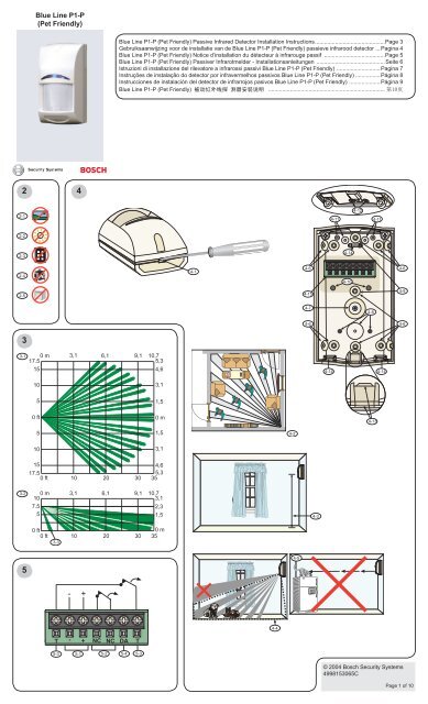
Blue Line P1-P (Pet Friendly) Passive Infrared Detector <strong>Installation</strong> <strong>Instructions</strong> .............................................Page 3<br />
Gebruiksaanwijzing voor de installatie van de Blue Line P1-P (Pet Friendly) passieve infrarood detector ... Pagina 4<br />
Blue Line P1-P (Pet Friendly) Notice d’installation du détecteur à infrarouge passif .......................................Page 5<br />
Blue Line P1-P (Pet Friendly) Passiver Infrarotmelder - <strong>Installation</strong>sanleitungen ............................................Seite 6<br />
Istruzioni di installazione del rilevatore a infrarossi passivi Blue Line P1-P (Pet Friendly) ............................Pagina 7<br />
Instruções de instalação do detector por infravermelhos passivos Blue Line P1-P (Pet Friendly) ................Página 8<br />
Instrucciones de instalación del detector de infrarrojos pasivos Blue Line P1-P (Pet Friendly) ....................Página 9<br />
Blue Line P1-P (Pet Friendly) ........................................................................... <br />
30<br />
T - + NC NC DA T<br />
5-3<br />
-<br />
+<br />
5-4<br />
5-1 5-2 5-3<br />
1,5<br />
0 m<br />
1,5<br />
3,1<br />
4,6<br />
5,3<br />
35<br />
0 m<br />
35<br />
4-1<br />
4-4<br />
4-2<br />
4-5<br />
4-6<br />
4-15<br />
4-7<br />
4-6<br />
4-3<br />
4-14<br />
4-12<br />
4-11 4-11<br />
4-10<br />
4-8<br />
4-14 4-14<br />
4-13<br />
4-6<br />
4-9<br />
4-6<br />
© 2004 Bosch Security Systems<br />
<strong>4998153065C</strong><br />
Page 1 of 10
6<br />
7<br />
6-2 6-3<br />
6-1<br />
6-4<br />
6-6<br />
6-5<br />
6-8<br />
6-7<br />
Bosch Security Systems<br />
130 Perinton Parkway<br />
Fairport, NY 14450-9199<br />
www.boschsecuritysystems.com<br />
© 2004 Bosch Security Systems<br />
<strong>4998153065C</strong><br />
Page 2 of 10
Blue Line P1-P<br />
(Pet Friendly ® )<br />
Passive Infrared Detector<br />
<strong>Installation</strong> <strong>Instructions</strong><br />
2<br />
<strong>Installation</strong> Considerations<br />
Not suitable for outdoor use (2-1).<br />
Never install the detector where<br />
the PIR is in constant alarm (LED<br />
on). The LED is off when properly<br />
installed.<br />
Point away from direct and indirect<br />
sunlight (2-2).<br />
Point away from glass or other<br />
objects that rapidly change<br />
temperatures (2-3, 2-4, and 2-5).<br />
5<br />
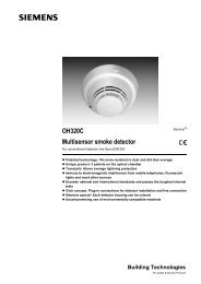
Terminal Block Wiring<br />
Terminal block (4-15) wiring:<br />
- 9 VDC to 15 VDC (5-1)<br />
- NC alarm contacts (5-2)<br />
- NC tamper contacts (5-3)<br />
- Digital alarm output (5-4)<br />
6<br />
1<br />
Specifi cations<br />
Input Power1 : 9 VDC to 15 VDC<br />
Current 10 mA @ 12 VDC standby<br />
Draw1 : Alarm current 18 mA<br />
Standby No internal standby battery. For UL Listed Product<br />
Power1 : <strong>Installation</strong>s, 4 hours (40 mAh) standby power must be provided by the control unit or by a UL Listed<br />
burglary power supply.<br />
Solid State Supervised Form “A” normally-closed (NC) rated for 125 mA at 28 VDC, 3 W.<br />
Relay2: Tamper2 : NC (with cover on) contacts rated at 28 VDC, 125 mA maximum. Connect tamper circuit to a 24-hour<br />
protection circuit.<br />
Digital Alarm 5 V normally, grounded during alarm<br />
Output:<br />
Temperature: -20°F to +120°F (-29°C to +49°C)<br />
For UL Listed installations, the temperature range is +32°F to +120°F (0°C to +49°C)<br />
Humidity: 0 to 95% non-condensing<br />
Dimensions: 4.2 in. x 2.4 in. x 1.9 in. (10.7 cm x 6.1 cm x 4.8 cm)<br />
Pet Immunity: Bosch Security Systems Pet Friendly Blue Line P1-P Passive Infrared (PIR) Detector does not<br />
detect pets up to 30 lb (13 kg) total or numerous rodents. The pet immunity feature was not tested<br />
by UL.<br />
Options: B335 Low Profi le Swivel Mount Bracket, B328 Gimbal Mount Bracket, and B338 Ceiling Bracket.<br />
These brackets can reduce the detector’s range and increase the dead zone area.<br />
Note: You cannot use a camera with the B338 Ceiling Mount Bracket.<br />
1 Use only a Listed limited-power source.<br />
3<br />
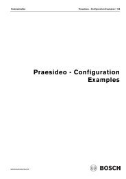
Coverage Patterns<br />
Top view (3-1)<br />
Side view (3-2)<br />
Optional look- down (3-3)<br />
LED Operation<br />
1. Select LED (6-1) operation:<br />
- Jumper position for LED on (6-2)<br />
- Jumper position for LED off (6-3)<br />
2. Non-pet installations only: Create a look-down zone directly below the<br />
detector by removing the tape covering the lens<br />
(6-4).<br />
Note: You cannot cover the look-down zone once the tape is<br />
removed.<br />
3. Replace the cover.<br />
4. To lock the cover (optional):<br />
a. Press the top of the cover tab (6-5) with your fi nger to lift the lower<br />
edge.<br />
b. Lift the lower end of cover tab with your fi nger (6-6) to open it.<br />
c. Insert a fl at head screwdriver in the slot (6-7) in the cover tab opening<br />
and turn it 180° to lock cover. Indicator points down (6-8).<br />
7<br />
Walk Test<br />
Note: Ensure the LED jumper is set to on (6-2).<br />
1. Wait at least 2 minutes after power up to start the Walk Test.<br />
The LED lights for 1 to 2 minutes until the detector<br />
stabilizes and no movement is detected for 2 seconds.<br />
The LED does not light when there is no motion.<br />
2. Watch the LED as you walk to the farthest edge of the pattern. Walk<br />
closer to the detector by crossing the pattern. The LED lights at the<br />
outside edge of the coverage range.<br />
4<br />
Mounting<br />
1. Insert a fl at head screwdriver in slot (4-1) and lift to open cover.<br />
2. Select a mounting location. Mount the sensor where an intruder is most<br />
likely to cross the coverage pattern (4-2).<br />
3. Mount the detector 7.5 ft to 9 ft (2.25 m to 2.7 m) above the fl oor (4-3).<br />
4. Pet mounting recommendations:<br />
- Range of pet immunity (4-4).<br />
- Do not point the detector where pets can climb (4-5).<br />
5. Optional: Mount the detector temporarily by peeling the blue tape off the<br />
back of the base to expose the adhesive. Do not use where adhesive<br />
can damage the wall.<br />
6. Mount the base using one of these options:<br />
- for surface or corner mounting, use the appropriate mounting holes (4-<br />
6) and the two fl at head screws and anchors provided.<br />
- use the optional B335 Bracket here (4-7).<br />
- use the optional B328 Bracket here (4-8).<br />
- use the optional B338 Bracket here (4-9).<br />
Note: Do not over tighten the mounting screws. The cover might not attach<br />
correctly.<br />
7. For the wall tamper function, insert the two pan head screws through the<br />
wall tamper knockouts (4-10). If needed, use the anchors provided to<br />
secure the screws.<br />
8. Wire the detector base. Thread the wires through the appropriate<br />
diameter wire knockouts on the detector base (4-11) or on the removable<br />
top insert (4-12).<br />
9. When wiring from below, thread wiring through these wire knockouts that<br />
are perpendicular to the base (4-13).<br />
10. Use the cable ties (4-14) for strain relief.<br />
Bosch Security Systems<br />
130 Perinton Parkway<br />
Fairport, NY 14450-9199<br />
www.boschsecuritysystems.com<br />
Pet Friendly ® is a registered<br />
trademark of Bosch Security<br />
Systems in the United States.<br />
© 2004 Bosch Security Systems<br />
<strong>4998153065C</strong><br />
Page 3 of 10
Gebruiksaanwijzing voor de<br />
installatie van de<br />
Blue Line P1-P<br />
(Pet Friendly)<br />
passieve infrarood detector<br />
2<br />
Niet geschikt voor buitengebruik<br />
(2-1).<br />
Nooit de detector installeren<br />
wanneer de PIR of microgolf in<br />
constant alarm is (LED aan). Bij<br />
correcte installatie is de LED uit.<br />
Niet richten op direct of indirect<br />
zonlicht (2-2).<br />
Niet op glas of andere voorwerpen<br />
richten die snel van temperatuur<br />
kunnen veranderen (2-3, 2-4, and<br />
2-5).<br />
5<br />
6<br />
7<br />
Aandachtspunten<br />
voor installatie<br />
Aansluitblokbedrading<br />
Aansluitblokbedrading (4-15):<br />
- 9 VDC t/m 15 VDC (5-1)<br />
- NC alarmcontacten (5-2)<br />
- NC tampercontacten (5-3)<br />
- Digitale alarmoutput (5-4)<br />
LED-werking<br />
1<br />
Technische beschrijving<br />
Ingangsvermogen: 9 VDC tot 15 VDC<br />
Stroom: 10 mA op 12 VDC stand-by<br />
Alarmstroom 18 mA<br />
Stand-by elektriciteit: Geen interne stand-by batterij.<br />
Halfgeleider relais * : Te selecteren toezichtsvorm “A” normaal gesloten (NC) berekend voor 125 mA op 28 VDC,<br />
3 W.<br />
Tamper * : NC (met kap) contacten geschat op 28 VDC, 125 mA maximaal. Verbind tamper met het 24uurs<br />
beschermingscircuit.<br />
Digitaal alarmoutput: 5 V normaal, aarding tijdens alarm<br />
Temperatuursgebied: -29°C t/m +49°<br />
Vochtigheid: 0 t/m 95% niet condenserend<br />
Afmetingen: 10,67 cm x 6,1 cm x 4,8 cm<br />
Ongevoelig voor Het security System Blue Line passieve infrarood (PIR) detector Pet<br />
huisdieren: Friendly (huisdiervriendelijk) van Bosch negeert huisdieren tot 13 kg en verscheidene<br />
knaagdieren.<br />
Opties: B335 Draaibare bevestigingsarm met laag profi el, B328 gyro-bevestigingsarm en B338<br />
plafondarm. Deze armen kunnen het bereik van de detector verkleinen en de grootte van het<br />
onwaarneembare gebied vergroten.<br />
Opmerking: Men kan met de B338 Plafondarm geen camera gebruiken.<br />
* Bedrading mag alleen worden aangesloten op een circuit dat een extra laag veiligheidsvoltage heeft.<br />
3 Bereikpatronen 4<br />
Bovenaanzicht (3-1)<br />
Zijaanzicht (3-2)<br />
Optioneel onderaanzicht (3-3)<br />
1. Kies LED (6-1) werking:<br />
- Springpositie voor LED aan (6-2)<br />
- Springpositie voor LED uit (6-3)<br />
2. Alleen voor huisdiergevoelige installaties: Creëer een gebied met<br />
benedenzicht direct onder de detector door de tape die de lens bedekt te<br />
verwijderen (6-4).<br />
Opmerking: U kunt het gebied met benedenzicht niet bedekken wanneer de<br />
tape eenmaal is verwijderd.<br />
3. Plaats de kap terug.<br />
4. Voor het op slot zetten van de kap (optioneel):<br />
a. Druk met uw vinger op de top van de beschermingskap (6-5) om de<br />
onderste rand op te lichten.<br />
b. Licht het onderste gedeelte van de beschermingskap met uw vinger<br />
op (6-6) om het te openen.<br />
c. Steek een platkopschroevendraaier in de groef (6-7) van de<br />
opening van de beschermingskap en draai het 180o om de kap af<br />
te sluiten. Indicator wijst naar beneden (6-8).<br />
Looptest<br />
Opmerking: Zorg er voor dat de LED springer aan staat (6-2).<br />
1. Wacht ten minste 2 minuten na inschakelen alvorens met de looptest te<br />
beginnen.<br />
De LED is gedurende 1 tot 2 minuten verlicht totdat de detector<br />
gestabiliseerd is en wanneer gedurende 2 seconden geen beweging<br />
waargenomen is.<br />
Als er geen beweging is, verlicht de LED niet.<br />
2. Houdt de LED in de gaten terwijl u naar het uiterste einde van het bereik<br />
loopt. Loop naar de detector toe en doorkruis daarmee het bereik. De<br />
LED-lichten aan de buitenrand van het gezichtsveld lichten op.<br />
Bevestiging<br />
1. Steek een platkopschroevendraaier in de groef (4-1) en licht op om de<br />
kap te openen.<br />
2. Kies een bevestigingsplaats. Bevestig de sensor waar een indringer<br />
meest waarschijnlijk het gezichtsveld zou kunnen doorkruisen (4-2).<br />
3. Bevestig de detector 2,25 tot 2,70 meter boven de vloer (4-3).<br />
4. Aanbevelingen m.b.t. bevestiging en huisdieren:<br />
- Bereik waarin huisdieren niet worden waargenomen (4-4).<br />
- Richt de detector niet op punten waar huisdieren kunnen komen (4-5).<br />
5. Optioneel: Bevestig de detector tijdelijk door de blauwe tape aan de<br />
achterkant van de basis te verwijderen. Gebruik niet op plaatsen waar<br />
de kleefstof schade aan de muur kan brengen.<br />
6. Bevestig de basis volgens één van de volgende opties:<br />
- gebruik voor bevestiging op een oppervlak of in de hoek de geschikte<br />
bevestigingsgaten (4-6) en de twee meegeleverde platkopschroeven<br />
en de ankers.<br />
- gebruik hier de optionele B335 arm (4-7).<br />
- gebruik hier de optionele B328 arm (4-8).<br />
- gebruik hier de optionele B338 arm (4-9).<br />
Opmerking: Draai de bevestigingsschroeven niet te vast aan. De kap kan<br />
dan mogelijk niet juist worden aangebracht.<br />
7. Voor de muurrefl ectiefunctie, steek de twee cilinderkopschroeven door<br />
de muurrefl ectie-gaatjes (4-10). Gebruik, indien nodig, de meegeleverde<br />
ankers om de schroeven vast te zetten.<br />
8. Voorzie de detectorbasis van bedrading. Geleid de bedrading door<br />
de daarvoor geschikte gaten op de detectorbasis (4-11) of op de<br />
verwijderbare topgroef (4-12).<br />
9. Wanneer bedrading van beneden af wordt aangelegd, geleid dan de<br />
draden door de bedoelde gaten die loodrecht op de basis staan (4-13).<br />
10. Gebruik de kabelbindingen (4-14) om de spanning te verlichten.<br />
Bosch Security Systems<br />
130 Perinton Parkway<br />
Fairport, NY 14450-9199<br />
www.boschsecuritysystems.com<br />
© 2004 Bosch Security Systems<br />
<strong>4998153065C</strong><br />
Pagina 4 von 10
Blue Line P1-P<br />
(Pet Friendly)<br />
Notice d’installation du<br />
détecteur à infrarouge passif<br />
2<br />
Ne pas utiliser à l’extérieur (2-1).<br />
Ne jamais installer le détecteur à un<br />
endroit où la cellule infrarouge passif<br />
(IPR) est constamment activée<br />
(voyant LED allumé). Si le détecteur<br />
est correctement installé, le voyant<br />
LED est éteint.<br />
Ne pas exposer à la lumière directe<br />
et indirecte du soleil (2-2).<br />
Ne pas diriger vers une vitre<br />
ou d’autres objets changeant<br />
rapidement de température (2-3, 2-4<br />
et 2-5).<br />
5<br />
6<br />
7<br />
Conseils relatifs à<br />
l’installation<br />
Câblage de la borne<br />
Câblage de la borne (4-15) :<br />
- de 9 Vcc à 15 Vcc (5-1)<br />
- Contacts d’alarme NF (5-2)<br />
- Contacts autoprotégés NF (5-3)<br />
- Sortie alarme numérique (5-4)<br />
Activation des voyants LED<br />
1<br />
Caractéristiques techniques<br />
Alimentation: de 9 Vcc à 15 Vcc<br />
Consommation: 10 mA @ 12 Vcc en repos<br />
18 mA en alarme<br />
Alimentation de<br />
secours:<br />
Pas de batterie de secours interne.<br />
Relais à<br />
semi-conducteurs<br />
Form “A” contrôlée normalement fermé (NF) calibré pour 125 mA à 28 Vcc, 3 W<br />
* :<br />
Autoprotection * : Contacts NF (avec capot) calibrés à 28 Vcc, 125 mA maximum. Connecter le circuit<br />
d’autoprotection à un circuit de protection fonctionnant 24h/24.<br />
Sortie alarme<br />
numérique :<br />
5 V au repos, à la masse lorsque l’alarme est déclenchée<br />
Température : de -29°C à +49°C (de -20°F à +120°F)<br />
Humidité : de 0 à 95% sans condensation<br />
Dimensions : 10,7 cm x 6,1 cm x 4,8 cm (4,2 po x 2,4 po x 1,9 po)<br />
Immunité aux Le détecteur à infrarouge passif (IRP) Blue Line P1-P Pet Friendly (avec immunité aux<br />
animaux animaux) de Bosch Security Systems ne détecte pas les animaux domestiques dont le poids<br />
domestiques : est inférieur à 13 kg ou autres petits animaux. .<br />
Options : Support sur pivot plat B335, sur rotule B328 et sur rotule B338 pour installation au plafond.<br />
Ces supports peuvent réduire le champ de détection et augmenter la zone d’angle mort.<br />
Remarque : le support sur rotule B338 pour une installation au plafond ne permet pas<br />
d’utiliser une caméra.<br />
* Prenez soin de connecter tous les fi ls à un circuit à très basse tension de sécurité (SELV).<br />
Diagrammes illustrant<br />
3 4<br />
le champ de détection<br />
Vue du dessus (3-1)<br />
Vue de côté (3-2)<br />
Détection vers le bas facultative<br />
(3-3)<br />
1. Sélectionnez un réglage LED (6-1) :<br />
- Position du cavalier pour voyant LED allumé (6-2)<br />
- Position du cavalier pour voyant LED éteint (6-3)<br />
2. Si vous ne possédez pas d’animaux domestiques : Créez une zone de<br />
détection vers le bas directement en-dessous du détecteur en retirant<br />
l’autocollant qui recouvre la lentille (6-4).<br />
Remarque : une fois retiré, l’autocollant ne peut pas être replacé afi n de<br />
supprimer la zone de détection vers le bas.<br />
3. Remettez le capot en place.<br />
4. Pour verrouiller le capot (facultatif) :<br />
a. Avec votre doigt, appuyez sur la partie supérieure de la languette<br />
du capot (6-5) pour que la partie inférieure se soulève.<br />
b. Soulevez l’extrémité inférieure de la languette (6-6) afi n d’ouvrir le<br />
capot.<br />
c. Insérez un tournevis à tête plate dans la fente (6-7) correspondant<br />
à l’ouverture de la languette et tournez-le à 180o pour verrouiller le<br />
capot. L’indicateur est dirigé vers le bas (6-8).<br />
Test de marche<br />
Remarque: vérifi ez que le cavalier LED est réglé sur On (6-2).<br />
1. Pour commencer le test de marche, patientez deux minutes après la mise<br />
sous tension.<br />
Le voyant LED s’allume pendant 1 ou 2 minutes, puis le détecteur se<br />
stabilise quand aucun mouvement n’est détecté pendant 2 secondes.<br />
Le voyant LED ne s’allume pas si aucun mouvement n’est détecté.<br />
2. Déplacez-vous jusqu’au point le plus éloigné du champ de détection<br />
tout en observant le voyant LED. Traversez de nouveau le champ et<br />
rapprochez-vous du détecteur. Le voyant LED s’allume sur le bord<br />
extérieur du champ de détection.<br />
<strong>Installation</strong><br />
1. Insérez un tournevis à tête plate dans la fente (4-1) et appuyez dessus<br />
pour soulever le capot.<br />
2. Déterminez où installer le détecteur. Installez-le à un endroit où le<br />
champ de détection sera inévitablement traversé en cas d’intrusion<br />
(4-2).<br />
3. Installez le détecteur à au moins 2,25 m du sol (maximum 2,7 m) (4-3).<br />
4. Recommandations d’installation si vous possédez des animaux :<br />
- Rayon d’immunité des animaux (4-4).<br />
- Ne pas diriger le détecteur vers des endroits où les animaux<br />
domestiques peuvent grimper (4-5).<br />
5. Facultatif : Installez le détecteur de façon temporaire en le faisant<br />
adhérer à l’emplacement souhaité à l’aide de l’autocollant situé au dos<br />
du socle (retirez la bande adhésive bleue). Ne le collez pas à un endroit<br />
où le mur pourra être abîmé.<br />
6. Fixez le socle en procédant de l’une des manières suivantes :<br />
- pour le fi xer sur une surface plane ou dans un angle, utilisez les trous<br />
de montage appropriés (4-6) et les deux vis à tête plate et brides<br />
d’ancrage fournies.<br />
- utilisez ici le support B335 facultatif (4-7).<br />
- utilisez ici le support B328 facultatif (4-8).<br />
- utilisez ici le support B338 facultatif (4-9).<br />
Remarque : ne serrez pas trop les vis de montage, vous pourriez ensuite<br />
avoir du mal à fi xer le capot.<br />
7. Pour la fonction d’autoprotection, insérez les deux vis à tête cylindrique<br />
dans les orifi ces pré-découpés prévus à cet effet<br />
(4-10). Si besoin est, utilisez les brides d’ancrage pour fi xer les vis.<br />
8. Reliez le socle du détecteur avec les fi ls. Passez les fi ls dans les orifi ces<br />
pré-découpés du socle (4-11) ou de la plaque supérieure amovible<br />
(4-12) dont les diamètres concordent.<br />
9. Si vous insérez les fi ls par dessous, passez-les dans les orifi ces<br />
pré-découpés perpendiculaires au socle (4-13).<br />
10. Assurez la tenue des fi ls (4-14) à<br />
l’aide des frettes.<br />
Bosch Security Systems<br />
130 Perinton Parkway<br />
Fairport, NY 14450-9199<br />
www.boschsecuritysystems.com<br />
© 2004 Bosch Security Systems<br />
<strong>4998153065C</strong><br />
Page 5 sur 10
Blue Line P1-P<br />
(Pet Friendly)<br />
Passiver Infrarotmelder -<br />
<strong>Installation</strong>sanleitungen<br />
2<br />
Nicht geeignet für den Einsatz im<br />
Freien (2-1).<br />
Der Melder darf unter keinen<br />
Umständen installiert werden,<br />
wenn sich der PIR-Sensor<br />
ständig im Alarmzustand<br />
befi ndet (LED eingeschaltet). Bei<br />
ordnungsgemäßer <strong>Installation</strong> ist die<br />
LED ausgeschaltet.<br />
Den Melder nicht ins direkte oder<br />
indirekte Sonnenlicht weisen lassen<br />
(2-2).<br />
Den Melder nicht auf Glas oder<br />
andere Objekte mit starken<br />
Temperaturschwankungen richten<br />
(2-3, 2-4 und 2-5).<br />
5<br />
6<br />
7<br />
Hinweise für die<br />
<strong>Installation</strong><br />
Anschlussblockverdrahtung<br />
Verdrahtung des Anschlussblocks (4-15):<br />
- 9 V DC bis 15 V DC (5-1)<br />
- Alarm-Öffnungskontakte (5-2)<br />
- Sabotageschutz-Öffnungskontakte (5-3)<br />
- Digitaler Alarmausgang (5-4)<br />
LED-Funktion<br />
1<br />
Technische Daten<br />
Eingangsleistung: 9 V DC bis 15 V DC<br />
Stromaufnahme: 10 mA bei 12 V DC (Ruhestrom)<br />
18 mA (Alarmstrom)<br />
Notstrom: Keine interne Notstrombatterie.<br />
Transistorrelais * : Überwachter Form A-Öffner mit 125 mA Nennleistung bei 28 V DC, 3 W.<br />
Sabotageschutz * : Öffner (bei geschlossener Abdeckung) mit Kontakt-Nennleistung bei max. 28V DC, 125 mA.<br />
Schließen Sie den Sabotageschutz-Stromkreis an eine ständig aktive Schutzschaltung an.<br />
Digitaler<br />
Alarmausgang:<br />
5 V normal, geerdet während Alarm<br />
Temperatur: -29°C bis +49°C<br />
Luftfeuchtigkeit: 0 bis 95%, nicht-kondensierend<br />
Abmessungen: 10,7 cm x 6,1 cm x 4,8 cm Ausschluss der<br />
Störung durch Der passive Pet Friendly Blue Line P1-P Infrarotmelder (PIR) von Bosch Security Systems<br />
Haustiere: ignoriert Haustiere mit einem Gesamtgewicht von bis zu 13 kg oder mehrere Nagetiere.<br />
Optionen: Schwenkbare B335-Halterung in Flachbauweise, kardanisch aufgehängte B328-Halterung<br />
und B338-Deckenhalterung. Diese Halterungen können zur Reduzierung der Reichweite des<br />
Melders und zur Vergrößerung des unbewachten Bereichs führen.<br />
Hinweis: Die B338-Deckenhalterung eignet sich nicht für den Einsatz mit Kamera.<br />
* Alle Drähte sind ohne Ausnahme an einen SELV-Stromkreis anzuschließen.<br />
3 Überwachungsbereiche 4<br />
Draufsicht (3-1)<br />
Seitenansicht (3-2)<br />
Optionaler Unterkriechschutz (3-3)<br />
1. Wählen Sie die LED-Funktion (6-1):<br />
- Drahtbrückenposition für LED on (ein) (6-2)<br />
- Drahtbrückenposition für LED off (aus) (6-3)<br />
2. Nur für <strong>Installation</strong>en ohne Störungen durch Haustiere: Für eine<br />
Unterkriechschutzzone direkt unter dem Melder entfernen Sie das<br />
Klebeband zum Abdecken der Linse (6-4).<br />
Hinweis: Sie können die Unterkriechschutzzone nach Entfernen des<br />
Klebebands nicht mehr abdecken.<br />
3. Bringen Sie die Abdeckung wieder an.<br />
4. Sie können die Abdeckung folgendermaßen abschließen (optional):<br />
a. Drücken Sie mit Ihrem Finger oben auf die Abdeckungshaltelasche<br />
(6-5), um die Unterkante anzuheben.<br />
b. Heben Sie zum Öffnen der Abdeckungshaltelasche deren Unterkante<br />
mit Ihrem Finger (6-6) an.<br />
c. Stecken Sie einen Senkkopf-Schraubendreher in den Schlitz (6-7) in<br />
der Abdeckungshaltelasche und drehen Sie ihn zum Abschließen der<br />
Abdeckung um 180o . Der Anzeiger weist nach unten (6-8).<br />
Gehtest<br />
Hinweis: Stellen Sie sicher, dass die LED-Drahtbrücke auf ON (EIN) (6-2)<br />
gesetzt ist.<br />
1. Warten Sie mindestens 2 Minuten nach dem Einschalten, bevor Sie mit<br />
dem Gehtest beginnen.<br />
Die LED leuchtet 1 bis 2 Minuten lang, bis sich der Melder stabilisiert hat<br />
und 2 Sekunden lang keine Bewegung erfasst wurde.<br />
Die LED leuchtet bei Bewegungslosigkeit nicht auf.<br />
2. Beobachten Sie die LED, während Sie an die äußerste Grenze des<br />
Überwachungsbereichs gehen. Nähern Sie sich dem Melder und<br />
durchqueren Sie dabei den Überwachungsbereich. Die LED leuchtet an der<br />
Außengrenze des Überwachungsbereichs auf.<br />
Montage<br />
1. Stecken Sie einen Senkkopf-Schraubendreher in den Schlitz<br />
(4-1) und heben Sie ihn zum Öffnen der Abdeckung an.<br />
2. Wählen Sie einen Montageort. Installieren Sie den Sensor an<br />
einer Stelle, an der ein Einbrecher höchstwahrscheinlich den<br />
Überwachungsbereich durchqueren würde (4-2).<br />
3. Montieren Sie den Melder 2,25 m bis 2,7 m über dem Boden<br />
(4-3).<br />
4. Montage bei möglichen Störungen durch Haustiere:<br />
- Bereich des Ausschlusses der Störung durch Haustiere (4-4).<br />
- Den Melder nicht auf Stellen richten, an denen Haustiere<br />
hochklettern können (4-5).<br />
5. Optional: Montieren Sie den Melder vorläufi g nach Entfernen des<br />
blauen Klebestreifens von der Rückseite des Gehäusebodens, um den<br />
Klebstoff freizulegen. Verwenden Sie Klebstoff nur dort, wo dieser die<br />
Wand nicht beschädigt.<br />
6. Die folgenden Montageoptionen stehen für den Gehäuseboden zur<br />
Verfügung:<br />
- Oberfl ächen- oder Eckmontage mit den entsprechenden<br />
Montagelöchern (4-6) und den beiden mitgelieferten Schrauben und<br />
Dübeln.<br />
- Einsatz der optionalen B335-Halterung (4-7).<br />
- Einsatz der optionalen B328-Halterung (4-8).<br />
- Einsatz der optionalen B338-Halterung (4-9).<br />
Hinweis: Die Montageschrauben dürfen nicht zu stark angezogen werden.<br />
Möglicherweise schließt die Abdeckung nicht mehr richtig.<br />
7. Für den Wand-Sabotageschutz stecken Sie die beiden<br />
Zylinderkopfschrauben durch die vorbereiteten Kabeldurchführungen<br />
am Wand-Sabotageschutz (4-10). Bei Bedarf verwenden Sie die<br />
mitgelieferten Dübel, um die Schrauben sicher zu montieren.<br />
8. Verdrahten Sie den Gehäuseboden. Führen Sie die Drähte durch die<br />
vorbereiteten Kabeldurchführungen mit entsprechendem Durchmesser<br />
im Gehäuseboden (4-11) oder im abnehmbaren oberen Einsatz (4-12).<br />
9. Beim Verdrahten von unten führen Sie die Drähte durch diese<br />
vorbereiteten Kabeldurchführungen, die senkrecht zum Gehäuseboden<br />
verlaufen (4-13).<br />
10. Verwenden Sie die Kabelbinder (4-14) für Zugentlastung.<br />
Bosch Security Systems<br />
130 Perinton Parkway<br />
Fairport, NY 14450-9199<br />
www.boschsecuritysystems.com<br />
© 2004 Bosch Security Systems<br />
<strong>4998153065C</strong><br />
Seite 6 von 10
Istruzioni di installazione del<br />
rilevatore a infrarossi passivi<br />
Blue Line P1-P<br />
(Pet Friendly)<br />
Informazioni<br />
2<br />
sull’installazione<br />
Non adatto per uso esterno (2-1).<br />
Non installare il rilevatore dove il<br />
PIR è in costante allarme (LED ON).<br />
Quando l’installazione è corretta, il<br />
LED è spento (OFF).<br />
Tenere lontano da fonti luminose<br />
dirette e indirette (2-2).<br />
Tenere lontano da vetro o altri<br />
oggetti che cambiano rapidamente<br />
la temperatura (2-3, 2-4 e 2-5).<br />
5<br />
Cablaggio della morsettiera (4-15):<br />
- da 9 Vcc a 15 Vcc (5-1)<br />
- contatti di allarme NC (5-2)<br />
- contatti di tamper NC (5-3)<br />
- uscita allarme digitale (5-4)<br />
6<br />
7<br />
Cablaggio della morsettiera<br />
Funzionamento dei LED<br />
1<br />
Specifi che tecniche<br />
Alimentazione: Da 9 Vcc a 15 Vcc<br />
Assorbimento di 10 mA @ 12 Vcc a riposo<br />
corrente: Corrente in allarme 18 mA<br />
Alimentazione di Nessuna batteria di riserva interna.<br />
riserva:<br />
Relè a stato solido*: Form “A” supervisionato normalmente chiuso (NC) da 125 mA a 28 Vcc, 3 W.<br />
Tamper * : Contatti NC (con coperchio nella sua sede) da 28 Vcc, 125 mA massimo. Collegare il circuito<br />
di tamper a una zona 24 ore in centrale.<br />
Uscita allarme Di norma 5 V, messa a terra durante l’allarme<br />
digitale:<br />
Temperatura: Da -29°C a +49°C<br />
Umidità: Da 0 a 95% senza condensa<br />
Dimensioni: 10,7 cm x 6,1 cm x 4,8 cm<br />
Immunità agli animali: Il rilevatore a infrarossi passivi (PIR) Blue Line P1-P dei sistemi di sicurezza Bosch Pet<br />
Friendly (amico degli animali) non rileva la presenza di animali per un peso massimo<br />
complessivo di 13 kg o di numerosi roditori.<br />
Opzioni: B335 Staffa per snodo a basso profi lo, B328 Staffa per montaggio su sospensione cardanica<br />
e B338 Staffa per montaggio a parete. Queste staffe possono ridurre il range del rilevatore e<br />
aumentare la “zona morta”.<br />
Nota: con la staffa per montaggio a parete B338 non è possibile utilizzare la telecamera.<br />
* Collegare tutti i cavi esclusivamente a un circuito SELV (bassissima tensione di sicurezza).<br />
3 Area di copertura 4<br />
Vista dall’alto (3-1)<br />
Vista laterale (3-2)<br />
Antistrisciamento opzionale (3-3)<br />
1. Scegliere il funzionamento dei LED (6-1):<br />
- Posizione del ponticello per il LED ON (6-2)<br />
- Posizione del ponticello per il LED OFF (6-3)<br />
2. Solo per le installazioni senza animali: creare un’area antistrisciamento<br />
direttamente al di sotto del rilevatore rimuovendo il nastro di copertura<br />
delle lenti (6-4).<br />
Nota: una volto rimosso il nastro non è possibile ricoprire l’area<br />
antistrisciamento.<br />
3. Riposizionare il coperchio.<br />
4. Per bloccare il coperchio (opzionale):<br />
a. Premere con le dita la parte superiore dell’aletta del coperchio (6-5)<br />
per sollevare il bordo inferiore.<br />
b. Sollevare con le dita l’estremità inferiore dell’aletta del coperchio<br />
(6-6) per aprirlo.<br />
c. Inserire un cacciavite a testa piatta nella fessura (6-7) creatasi<br />
dall’apertura dell’aletta del coperchio e girarlo di 180o per bloccare il<br />
coperchio. L’indicatore è rivolto verso il basso (6-8).<br />
Walk Test<br />
Nota: assicurarsi che il ponticello del LED sia impostato su ON (6-2).<br />
1. Dopo l’accensione attendere almeno 2 minuti prima di cominciare il Walk<br />
Test.<br />
I LED lampeggiano per 1 o 2 minuti fi no a quando il rilevatore non si<br />
stabilizza e non vengono rilevati movimenti per 2 secondi.<br />
Quando non c’è movimento, il LED non lampeggia.<br />
2. Osservare il LED mentre ci si dirige verso l’estremità più lontana dell’area<br />
di copertura. Avvicinarsi al rilevatore attraversando l’area di copertura. Il<br />
LED lampeggia all’estremità esterna dell’area di copertura.<br />
Montaggio<br />
1. Inserire un cacciavite a testa piatta nella fessura (4-1) facendo leva per<br />
aprire il coperchio.<br />
2. Scegliere un’ubicazione per il montaggio. Installare il rilevatore in un<br />
luogo in cui sia probabile che l’intruso ne attraversi l’area di copertura<br />
(4-2).<br />
3. Posizionare il rilevatore a un’altezza compresa tra 2,25 m e 2,7 m dal<br />
pavimento (4-3).<br />
4. Consigli per il montaggio in presenza di animali:<br />
- Range di immunità agli animali domestici (4-4).<br />
- Non installare il rilevatore in luoghi in cui potrebbero arrampicarsi<br />
animali (4-5).<br />
5. Opzionale: per il montaggio provvisorio del rilevatore, rimuovere il nastro<br />
blu dal retro della base in modo da scoprire l’adesivo. Non utilizzare nei<br />
luoghi in cui l’adesivo può danneggiare il muro.<br />
6. Montare la base utilizzando una delle opzioni riportate di seguito:<br />
- per il montaggio a parete o ad angolo, utilizzare i fori appropriati (4-6)<br />
e le due viti a testa piatta e le ancore fornite in dotazione.<br />
- utilizzare la staffa opzionale B335 nella posizione indicata nella fi gura<br />
(4-7).<br />
- utilizzare la staffa opzionale B328 nella posizione indicata nella fi gura<br />
(4-8).<br />
- utilizzare la staffa opzionale B338 nella posizione indicata nella fi gura<br />
(4-9).<br />
Nota: se si stringono eccessivamente le viti di montaggio, il coperchio<br />
potrebbe non fi ssarsi correttamente.<br />
7. Per la funzione tamper a parete, inserire le due viti a testa tronco-conica<br />
attraverso i fori pretranciati del tamper a parete (4-10). Se necessario,<br />
utilizzare le ancore fornite in dotazione per fi ssare le viti.<br />
8. Cablare la base del rilevatore. Inserire i cavi attraverso i fori pretranciati<br />
di diametro appropriato sulla base del rilevatore (4-11) oppure sulla<br />
copertura rimovibile (4-12).<br />
9. Se si esegue il cablaggio dal basso, inserire i cavi attraverso i fori<br />
pretranciati perpendicolari alla base (4-13).<br />
10. Utilizzare le fascette per cavi (4-14) come serracavi.<br />
Bosch Security Systems<br />
130 Perinton Parkway<br />
Fairport, NY 14450-9199<br />
www.boschsecuritysystems.com<br />
© 2004 Bosch Security Systems<br />
<strong>4998153065C</strong><br />
Pagina 7 di 10
Instruções de instalação do<br />
detector por infravermelhos<br />
passivos<br />
Blue Line P1-P<br />
(Pet Friendly)<br />
2<br />
Não é adequado para utilizar no<br />
exterior (2-1).<br />
Nunca instale o detector onde<br />
o PIR esteja sempre em alarme<br />
constante (LED ligado). O LED está<br />
desligado quando o sistema estiver<br />
correctamente instalado.<br />
Não aponte para a luz solar directa<br />
e indirecta (2-2).<br />
Não aponte para vidros ou<br />
outros objectos que possam<br />
alterar rapidamente a respectiva<br />
temperatura (2-3, 2-4 e 2-5).<br />
5<br />
6<br />
7<br />
Notas de instalação<br />
Cablagem do bloco de terminais<br />
Cablagem do bloco de terminais (4-15):<br />
- 9 VCC a 15 VCC (5-1)<br />
- Contactos do alarme NF (5-2)<br />
- Contactos do tamper NF (5-3)<br />
- Saída do alarme digital (5-4)<br />
Funcionamento do LED<br />
1<br />
Especifi cações<br />
Alimentação de 9 VCC a 15 VCC<br />
entrada:<br />
Tomada de corrente: 10 mA @ 12 VCC em standby<br />
Corrente do alarme 18 mA<br />
Alimentação de Sem bateria interna de standby.<br />
standby:<br />
Relé de estado Form “A” supervisionada, contactos normalmente fechados (NF) com capacidade nominal<br />
sólido * : de 125 mA a 28 VCC, 3W.<br />
Tamper * : Contactos NF (com tampa) com potência nominal de 28 VCC, 125 mA, no máximo. Ligue o<br />
circuito tamper a um circuito de protecção de 24 horas.<br />
Saída do alarme Normalmente 5 V, ligado à terra durante o alarme<br />
digital:<br />
Temperatura: -29°C a +49°C (-20°F a +120°F)<br />
Humidade: 0 a 95% sem condensação<br />
Dimensões: 10,7 cm x 6,1 cm x 4,8 cm (4,2” x 2,4” x 1,9”)<br />
Imunidade aos O detector por infravermelhos passivos Blue Line P1-P Pet Friendly (imune aos animais<br />
animais domésticos: domésticos) da Bosch Security Systems não detecta animais domésticos até 13 Kg no total<br />
ou vários roedores.<br />
Opções: Suporte de montagem com perno de baixo perfi l B335, Suporte de montagem em suspensão<br />
B328 e Suporte de montagem no tecto B338. Estes suportes podem reduzir o alcance do<br />
detector e aumentar a zona de ângulo morto.<br />
Nota: Não pode utilizar uma câmara com o Suporte de montagem no tecto B338.<br />
* Ligue todas as cablagens apenas a um circuito de segurança de tensão extra baixa (SELV).<br />
3 Zonas de cobertura 4<br />
Vista superior (3-1)<br />
Vista lateral (3-2)<br />
Vista de cima opcional (3-3)<br />
1. Seleccione o funcionamento do LED (6-1):<br />
- Posição do comutador para o LED ligado (6-2)<br />
- Posição do comutador para o LED desligado (6-3)<br />
2. Apenas para as instalações sem animais domésticos: Crie uma zona vista<br />
de cima directamente abaixo do detector removendo a fi ta-cola que cobre<br />
a objectiva (6-4).<br />
Nota: Não pode tapar a zona de vista de cima quando a fi ta-cola tiver sido<br />
removida.<br />
3. Volte a colocar a tampa.<br />
4. Para trancar a tampa (opcional):<br />
a. Prima o topo da patilha da tampa (6-5) com o dedo para levantar o<br />
rebordo inferior.<br />
b. Levante a extremidade inferior da patilha da tampa com o dedo<br />
(6-6) para a abrir.<br />
c. Insira uma chave de parafusos de cabeça chata na ranhura<br />
(6-7) da abertura da patilha da tampa e rode-a 180º para trancar a<br />
tampa. O indicador aponta para baixo (6-8).<br />
Teste de passagem<br />
Nota: Certifi que-se de que o comutador do LED está na posição ligado (6-2).<br />
1. Aguarde pelo menos 2 minutos após ligar para iniciar o teste de<br />
passagem.<br />
O LED acende-se durante 1 ou 2 minutos até que o detector estabilize e<br />
não seja detectado movimento durante 2 segundos.<br />
O LED não se acende enquanto não existir movimento.<br />
2. Observe o LED à medida que caminha para a extremidade mais afastada<br />
da zona. Caminhe mais perto do detector atravessando a zona. O LED<br />
acende-se na extremidade exterior da zona de cobertura.<br />
Montagem<br />
1. Insira uma chave de parafusos de cabeça chata na ranhura (4-1) e<br />
levante para abrir a tampa.<br />
2. Seleccione um local de montagem. Monte o sensor onde é mais<br />
provável que um intruso passe na zona de cobertura (4-2).<br />
3. Monte o detector entre 2,25 m a 2,7 m (7,5 pés a 9 pés) em relação ao<br />
solo (4-3).<br />
4. Recomendações de montagem tendo em conta os animais domésticos:<br />
- Alcance da imunidade aos animais domésticos (4-4).<br />
- Não aponte o detector para um local onde os animais domésticos<br />
possam subir (4-5).<br />
5. Opcional: Monte temporariamente o detector retirando a fi ta-cola azul<br />
da parte posterior da base, de forma a expor o adesivo. Não utilize num<br />
local em que o adesivo possa danifi car a parede.<br />
6. Monte a base de acordo com uma destas opções:<br />
- para a montagem de superfície ou em cantos, utilize os orifícios de<br />
montagem adequados (4-6) e os dois parafusos de cabeça chata e<br />
suportes fornecidos.<br />
- utilize neste local o suporte opcional B335 (4-7).<br />
- utilize neste local o suporte opcional B328 (4-8).<br />
- utilize neste local o suporte opcional B338 (4-9).<br />
Nota: Não aperte em demasia os parafusos de montagem. A tampa pode<br />
não fi car bem presa.<br />
7. Para a função de tamper de parede, insira dois parafusos de cabeça<br />
redonda nos orifícios de recorte do tamper de parede (4-10). Se<br />
necessário, utilize os suportes fornecidos para fi xar os parafusos.<br />
8. Ligue a cablagem da base do detector. Passe os fi os pelos orifícios com<br />
o recorte de diâmetro adequado na base do detector (4-11) ou na tampa<br />
superior amovível (4-12).<br />
9. Ao efectuar a ligação dos fi os a partir de baixo, passe os mesmos pelos<br />
orifícios que estão perpendiculares à base (4-13).<br />
10. Utilize braçadeiras de cabos (4-14) para aliviar a pressão.<br />
Bosch Security Systems<br />
130 Perinton Parkway<br />
Fairport, NY 14450-9199<br />
www.boschsecuritysystems.com<br />
© 2004 Bosch Security Systems<br />
<strong>4998153065C</strong><br />
Página 8 de 10
Instrucciones de instalación<br />
del detector de infrarrojos<br />
pasivos<br />
Blue Line P1-P<br />
(Pet Friendly)<br />
Consejos de<br />
2<br />
instalación<br />
El aparato no debe instalarse en el<br />
exterior (2-1).<br />
Nunca instale el detector en lugares<br />
en los que los infrarrojos pasivos<br />
o las microondas estén en alarma<br />
constante (LED encendido). El LED<br />
se apaga cuando está correctamente<br />
instalado.<br />
No oriente el dispositivo hacia luz<br />
solar directa e indirecta (2-2).<br />
No oriente el dispositivo hacia<br />
cristales u otros objetos que puedan<br />
cambiar rápidamente de temperatura<br />
(2-3, 2-4 y 2-5).<br />
5<br />
Conexión del bloque terminal (4-15):<br />
- de 9 Vcc a 15 Vcc (5-1)<br />
- Contactos de alarma NC (5-2)<br />
- Contactos NC de bucle de antisabotaje (5-3)<br />
- Salida de alarma digital (5-4)<br />
6<br />
7<br />
Conexión del bloque terminal<br />
Funcionamiento del LED<br />
1<br />
Especifi caciones<br />
Alimentación: de 9 a 15 Vcc<br />
Consumo de corriente: 10 mA @ 12 Vcc en reposo<br />
18 mA en alarma<br />
Alimentación en reposo: No incorpora batería interna en reposo.<br />
Relé de estado sólido * : Form “A” supervisado fl otante NC (normally-closed) especifi cado para 125 mA a 28 Vcc,<br />
3 W.<br />
Bucle de antisabotaje * : Contactos NC (cubiertos) especifi cados a 28 Vcc, 125 mA de máximo. Conecte el circuito<br />
de bucle de antisabotaje a un circuito de protección 24 horas.<br />
Salida de alarma digital: Por lo general 5 V; actúa como toma de tierra durante la alarma<br />
Temperatura: -29°C a +49°C (-20°F a +120°F)<br />
Humedad: de 0 a 95% sin condensación<br />
Dimensiones: 10,7 cm x 6,1 cm x 4,8 cm (4,2 pulg. x 2,4 pulg. x 1,9 pulg.)<br />
Inmunidad de El detector de infrarrojos pasivos Pet Friendly (Compatible con animales domésticos)<br />
animales domésticos: Blue Line P1-P de Bosch Security Systems, no detecta animales domésticos de hasta 13<br />
kg (30 lb) o grupos de roedores.<br />
Opciones: Soporte de bajo perfi l de montaje en pared B335, soporte de cabezal Gimbal B328 y<br />
soporte de montaje de techo B338. Estos soportes pueden reducir el rango del detector y<br />
aumentar la zona de ángulo muerto.<br />
Nota: Esta cámara no se puede utilizar con un soporte de montaje de techo B338.<br />
* Conecte el cableado únicamente a un circuito de seguridad para voltajes muy bajos (SELV).<br />
3 Patrones de cobertura<br />
4<br />
1. Seleccione el funcionamiento del LED (6-1):<br />
- Posición del interruptor para el LED encendido (6-2)<br />
- Posición del interruptor para el LED apagado (6-3)<br />
2. Únicamente para instalaciones sin animales domésticos: Cree una zona<br />
de vista inferior directamente debajo del detector retirando la cinta que<br />
cubre la lente (6-4).<br />
Nota: Una vez haya retirado la cinta ya no podrá cubrir la zona de vista<br />
inferior.<br />
3. Vuelva a colocar la tapa.<br />
4. Para bloquear la tapa (opcional):<br />
a. Presione la parte superior de la pestaña de la tapa (6-5) con el dedo<br />
para levantar la parte inferior.<br />
b. Levante la parte inferior de la pestaña con el dedo (6-6) para abrirla.<br />
c. Introduzca un destornillador de cabeza plana en la ranura (6-7)<br />
de la pestaña de la tapa y gírelo 180º para bloquear la tapa. El<br />
indicador señala hacia abajo (6-8).<br />
Prueba de paseo<br />
Vista superior (3-1)<br />
Vista lateral (3-2)<br />
Vista inferior opcional (3-3)<br />
Nota: Asegúrese de que el interruptor del LED (indicador luminoso) está en la<br />
posición On (encendido) (6-2).<br />
1. Espere al menos 2 minutos después del encendido para comenzar la<br />
prueba de paseo.<br />
El LED se enciende de 1 a 2 minutos hasta que el detector se estabiliza y<br />
no se detectan movimientos durante 2 segundos.<br />
El LED no se enciende si no se detecta movimiento.<br />
2. Observe el LED mientras camina hasta el extremo del patrón. Acérquese<br />
del detector cruzando el patrón de cobertura. El LED se enciende en el<br />
extremo exterior del rango de cobertura.<br />
Montaje<br />
1. Introduzca un destornillador de cabeza plana en la ranura (4-1) y levante<br />
para abrir la tapa.<br />
2. Seleccione una ubicación para el montaje. Coloque el sensor donde sea<br />
más probable que un intruso cruce el patrón de cobertura (4-2).<br />
3. Sitúe el detector de 2,25 m a 2,7 m (7,5 pies a 9 pies) del suelo (4-3).<br />
4. Recomendaciones de montaje cuando existen animales domésticos:<br />
- Rango de inmunidad de animales domésticos (4-4).<br />
- No oriente el detector hacia lugares a los que puedan trepar los<br />
animales domésticos (4-5).<br />
5. Opcional: Monte el detector de forma provisional despegando la cinta<br />
azul de la parte trasera de la base para descubrir el adhesivo. No lo<br />
utilice en paredes que puedan quedar dañadas por el adhesivo.<br />
6. Monte la base siguiendo una de estas opciones:<br />
- para el montaje sobre superfi cies o esquinas, utilice las ranuras de<br />
montaje correspondientes (4-6) y los tornillos de cabeza plana y<br />
anclajes provistos.<br />
- utilice aquí el soporte B335 opcional (4-7).<br />
- utilice aquí el soporte B328 opcional (4-8).<br />
- utilice aquí el soporte B338 opcional (4-9).<br />
Nota: No fi je demasiado los tornillos de montaje. Puede que la tapa no<br />
encaje correctamente.<br />
7. Para la función de bucle de antisabotaje de pared, introduzca los<br />
dos tornillos de cabeza redonda en las aberturas ciegas del bucle de<br />
antisabotaje de pared (4-10). Si es necesario, puede utilizar los anclajes<br />
para asegurar los tornillos.<br />
8. Conecte la base del detector. Pase los cables por las aberturas ciegas<br />
para cable del diámetro correcto situadas en la base del detector (4-11)<br />
o en la tapa superior extraíble (4-12).<br />
9. Si efectúa la conexión desde abajo, pase el cableado a través de las<br />
aberturas ciegas para cable perpendiculares a la base (4-13).<br />
10. Utilice los anclajes de plástico (4-14) para liberar tensión.<br />
Bosch Security Systems<br />
130 Perinton Parkway<br />
Fairport, NY 14450-9199<br />
www.boschsecuritysystems.com<br />
© 2004 Bosch Security Systems<br />
<strong>4998153065C</strong><br />
Página 9 de 10
Blue Line P1-P<br />
(Pet Friendly)<br />
<br />
<br />
2<br />
<br />
<br />
<br />
<br />
<br />
<br />
<br />
<br />
<br />
<br />
5<br />
<br />
<br />
<br />
<br />
<br />
<br />
6<br />
<br />
7<br />
1<br />
<br />
<br />
<br />
<br />
<br />
<br />
<br />
<br />
<br />
<br />
<br />
<br />
<br />
<br />
<br />
<br />
<br />
* <br />
3 4<br />
<br />
<br />
<br />
<br />
<br />
<br />
<br />
<br />
<br />
<br />
<br />
<br />
<br />
<br />
<br />
<br />
<br />
<br />
<br />
<br />
<br />
<br />
<br />
<br />
<br />
<br />
<br />
<br />
<br />
<br />
<br />
<br />
<br />
<br />
<br />
<br />
<br />
<br />
<br />
<br />
<br />
<br />
<br />
<br />
<br />
<br />
<br />
<br />
Bosch Security Systems<br />
130 Perinton Parkway<br />
Fairport, NY 14450-9199<br />
www.boschsecuritysystems.com<br />
© 2004 Bosch Security Systems<br />
<strong>4998153065C</strong><br />
1010