Erection method 1275 to 1600 kg Motor XAF4 V = 1,00 ... - TEF-online
Erection method 1275 to 1600 kg Motor XAF4 V = 1,00 ... - TEF-online
Erection method 1275 to 1600 kg Motor XAF4 V = 1,00 ... - TEF-online

You also want an ePaper? Increase the reach of your titles
YUMPU automatically turns print PDFs into web optimized ePapers that Google loves.
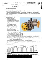
NC91A50-2<br />
Mises à jour<br />
N° 91 671 <strong>00</strong>0<br />
A : 29/07/10<br />
Page : 1/127<br />
Le : 09 / 07 / 10<br />
TE DOC 141-03/01 Par : Développement<br />
ThyssenKrupp Eleva<strong>to</strong>r<br />
Manufacturing France<br />
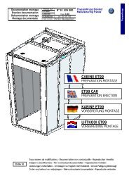
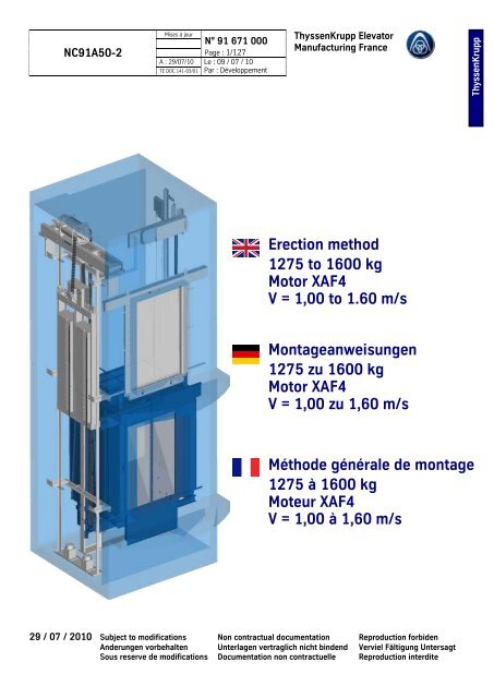
<strong>Erection</strong> <strong>method</strong><br />
<strong>1275</strong> <strong>to</strong> <strong>16<strong>00</strong></strong> <strong>kg</strong><br />
Mo<strong>to</strong>r <strong>XAF4</strong><br />
V = 1,<strong>00</strong> <strong>to</strong> 1.60 m/s<br />
Montageanweisungen<br />
<strong>1275</strong> zu <strong>16<strong>00</strong></strong> <strong>kg</strong><br />
Mo<strong>to</strong>r <strong>XAF4</strong><br />
V = 1,<strong>00</strong> zu 1,60 m/s<br />
Méthode générale de montage<br />
<strong>1275</strong> à <strong>16<strong>00</strong></strong> <strong>kg</strong><br />
Moteur <strong>XAF4</strong><br />
V = 1,<strong>00</strong> à 1,60 m/s<br />
29 / 07 / 2010 Subject <strong>to</strong> modifications Non contractual documentation Reproduction forbiden<br />
Anderungen vorbehalten Unterlagen vertraglich nicht bindend Verviel Fältigung Untersagt<br />
Sous reserve de modifications Documentation non contractuelle Reproduction interdite<br />
TK
NC91A50-2<br />
Mises à jour<br />
N° 91 671 <strong>00</strong>0<br />
A : 29/07/10<br />
Page : 2/127<br />
Le : 09 / 07 / 10<br />
TE DOC 141-03/01 Par : Développement<br />
Update index A / Aktualisierung Index A / Mise à jour indice A<br />
Add missing translations<br />
Hinzufügen fehlende Ubersetzungen<br />
Ajout des traductions manquantes<br />
ThyssenKrupp Eleva<strong>to</strong>r<br />
Manufacturing France<br />
Page<br />
TK
NC91A50-2<br />
Mises à jour<br />
Summary / Auszugs / Sommaire<br />
Phase<br />
N° 91 671 <strong>00</strong>0<br />
A : 29/07/10<br />
Page : 3/127<br />
Le : 09 / 07 / 10<br />
TE DOC 141-03/01 Par : Développement<br />
ThyssenKrupp Eleva<strong>to</strong>r<br />
Manufacturing France<br />
Working in safety<br />
Sicherheitsmassnahmen beim Arbeiten<br />
Travail en sécurité ---------------------------------------------------------------------------------- 10<br />
Safety instructions<br />
Sicherheitsanweisungen<br />
Consignes de sécurité ------------------------------------------------------------------------------ 11<br />
Foreword<br />
Präambel<br />
Préambules ------------------------------------------------------------------------------------------ 12<br />
Prerequisites<br />
Vorschriften<br />
Prérequis --------------------------------------------------------------------------------------------- 13<br />
Special <strong>to</strong>ols<br />
Spezialwerkzeug<br />
Outillage spécifique --------------------------------------------------------------------------------- 14<br />
Anforderungen: Stromversorgung in der obersten Haltestelle<br />
Prerequisite: Electricity supply at terminal level<br />
Pré-requis: Alimentation électrique au dernier niveau ----------------------------------------- 17<br />
Installation<br />
Gerüst im Schachtkopf<br />
Echafaudage haut de gaine ----------------------------------------------------------------------- 18<br />
1.<strong>00</strong> Return and deflection pulleys ---------------------------------------------------------------------- 19<br />
Umlenkrollen und Aufhängung<br />
Poulies de renvoi et mouflage<br />
Screws and nuts <strong>to</strong> be used ----------------------------------------------------------------------- 20<br />
Zu verwendende Schrauben<br />
Boulonnerie a utiliser<br />
2.<strong>00</strong> Scaffolding principle -------------------------------------------------------------------------------- 22<br />
Gerüstprinzip<br />
Principe d’échafaudage<br />
3.<strong>00</strong> Setting up the site lightin --------------------------------------------------------------------------- 30<br />
Montage der Baustellenbeleuchtung<br />
Mise en place de l’éclairage de chantier<br />
4.<strong>00</strong> Fitting the load hooks ------------------------------------------------------------------------------- 31<br />
Montage der Transporthaken<br />
Mise en place des crochets de manutention<br />
5.<strong>00</strong> Setting up the hoist --------------------------------------------------------------------------------- 36<br />
Montage des Hebegerätes<br />
Mise en place de l’appareil de levage<br />
6.<strong>00</strong>Fitting the plumb angle iron ------------------------------------------------------------------------ 37<br />
Montage der Senklotleiste<br />
Mise en place dela ferrure de plombage<br />
TK
NC91A50-2<br />
Mises à jour<br />
Summary / Auszugs / Sommaire<br />
N° 91 671 <strong>00</strong>0<br />
A : 29/07/10<br />
Page : 4/127<br />
Le : 09 / 07 / 10<br />
TE DOC 141-03/01 Par : Développement<br />
ThyssenKrupp Eleva<strong>to</strong>r<br />
Manufacturing France<br />
7.<strong>00</strong> Shaft plumbing and measuring ------------------------------------------------------------------- 39<br />
Abmessen des Schachts<br />
Relevé de gaine<br />
8.<strong>00</strong> Positioning the plumb angle iron ------------------------------------------------------------------ 40<br />
Positionerung der Senklotleiste<br />
Positionnement de la ferrure de plombage<br />
9.<strong>00</strong> Introducing the guide rails ------------------------------------------------------------------------- 41<br />
Einführen der Führungen<br />
Introduction des guides<br />
10.<strong>00</strong> Fixing the buffer guide bay ------------------------------------------------------------------------- 42<br />
Befestigung des Grubenelements<br />
Fixation de la goulotte de cuvette<br />
11.<strong>00</strong> Fixing the pit ladder --------------------------------------------------------------------------------- 43<br />
Befestigung der Leiter in der Schachtgrube<br />
Fixation de l'échelle de cuvette<br />
12.<strong>00</strong> Machine supporting beams ------------------------------------------------------------------------ 45<br />
Traversen Maschinenträger<br />
Traverses support machine<br />
13.<strong>00</strong> Fitting the guide rail fixing brackets (level 0) ---------------------------------------------------- 50<br />
Montage der Führungsbeschläge (Haltestelle 0)<br />
Mise en place des ferrures de guidage (Niveau 0 )<br />
14.<strong>00</strong> First car guide rail sections ------------------------------------------------------------------------ 51<br />
Erste Führungsschiene der Kabine<br />
Première barre de guide cabine<br />
15.<strong>00</strong>Fitting the pit buffers (V = 1.<strong>00</strong> m/s) -------------------------------------------------------------- 52<br />
Montage der Puffer in der Schachtgrube (V = 1,<strong>00</strong> m/Sek)<br />
Mise en place des amortisseurs cuvette (V = 1.<strong>00</strong> m/s)<br />
16.<strong>00</strong> Fitting the pit buffers (V < 1.60 m/s) -------------------------------------------------------------- 53<br />
Montage der Puffer in der Schachtgrube (V < 1,60 m/Sek)<br />
Mise en place des amortisseurs cuvette (V < 1.60 m/s)<br />
17.<strong>00</strong> Introducing the <strong>to</strong>p and bot<strong>to</strong>m beams ---------------------------------------------------------- 54<br />
Einführung der unteren und oberen Traversen<br />
Introduction des traverses inférieure et supérieure<br />
18.<strong>00</strong> Adjusting the guide rail fixing bracket (Level 0) ------------------------------------------------- 55<br />
Einstellung der Führungsbeschläge (Haltestelle 0)<br />
Réglage de la ferrure de guidage (Niveau 0 )<br />
19.<strong>00</strong> Fitting the first counterweight guide rail section ------------------------------------------------- 57<br />
Montage der ersten Führungsschienen der Gegengewichte<br />
Mise en place de la première barre de guide contrepoids<br />
20.<strong>00</strong> Fitting the counterweight frame ------------------------------------------------------------------- 58<br />
Montage des Rahmens der Gegengewichte<br />
Mise en place du cadre de contrepoids<br />
TK
NC91A50-2<br />
Mises à jour<br />
Summary / Auszugs / Sommaire<br />
N° 91 671 <strong>00</strong>0<br />
A : 29/07/10<br />
Page : 5/127<br />
Le : 09 / 07 / 10<br />
TE DOC 141-03/01 Par : Développement<br />
ThyssenKrupp Eleva<strong>to</strong>r<br />
Manufacturing France<br />
21.<strong>00</strong> Fitting the second counterweight guide rail section -------------------------------------------- 59<br />
Montage der zweiten Führungsschiene der Gegengewichte<br />
Mise en place de la deuxieme barre de guide contrepoids<br />
22.<strong>00</strong> Partial loading of the counterweight -------------------------------------------------------------- 60<br />
Teilweises Beladen der Gegengewichte<br />
Chargement partiel du contrepoids<br />
23.<strong>00</strong> Fitting the uprights ---------------------------------------------------------------------------------- 62<br />
Montage der Pfosten<br />
Mise en place des montants<br />
24.<strong>00</strong> Fitting of safety gear switch and rope retaining plate ------------------------------------------ 63<br />
Montage des Schaltkontakts und Seilschutzes<br />
Mise en place du contact et du garde câble<br />
25.<strong>00</strong> Setting up the work platform ---------------------------------------------------------------------- 64<br />
Montage der Arbeitsplattform<br />
Mise en place de la plateforme de travail<br />
26.<strong>00</strong> Fitting the guardrails -------------------------------------------------------------------------------- 65<br />
Montage der Schutzvorrichtungen<br />
Mise en place des protections<br />
27.<strong>00</strong> Setting the <strong>to</strong>p fixing bracket ---------------------------------------------------------------------- 66<br />
Montage der oberen Befestigung der Führungen<br />
Mise en place de la fixation supérieure<br />
28.<strong>00</strong> Fishplating the guide rails (travel < 30 m). Principle-------------------------------------------- 68<br />
Verbindung der Führungen mit S<strong>to</strong>sslaschen (Schachthöhe < 30 m). Grundsatz<br />
Éclissage des gudes (course < 30 m). Principe<br />
29.<strong>00</strong> Fishplating the guide rails (travel > 30 m). Principle-------------------------------------------- 70<br />
Verbindung der Führungen mit S<strong>to</strong>sslaschen (Schachthöhe > 30 m). Grundsatz<br />
Éclissage des gudes (course > 30 m). Principe<br />
30.<strong>00</strong> Setting up the fixed point on the guide rails ----------------------------------------------------- 71<br />
Montage des Festpunktes der Führungen<br />
Mise en place du point fixe sur les guides<br />
31.01 Fitting the speed governor (B) --------------------------------------------------------------------- 72<br />
Montage des Geschwindigkeitsbegrenzers (B)<br />
Mise en place du limiteur de vitesse (B)<br />
31.02 Fitting the speed governor (C) --------------------------------------------------------------------- 73<br />
Montage des Geschwindigkeitsbegrenzers (C)<br />
Mise en place du limiteur de vitesse (C)<br />
31.03 Fitting the speed governor (specefic)) ------------------------------------------------------------ 74<br />
Montage des Geschwindigkeitsbegrenzers (spezifisch)<br />
Mise en place du limiteur de vitesse (spécifique)<br />
32.<strong>00</strong> Fitting the bot<strong>to</strong>m governor tension jack --------------------------------------------------------- 75<br />
Montage des Spanners des untern Begrenzers<br />
Mise en place du tendeur de limiteur inférieur<br />
TK
NC91A50-2<br />
Mises à jour<br />
Summary / Auszugs / Sommaire<br />
N° 91 671 <strong>00</strong>0<br />
A : 29/07/10<br />
Page : 6/127<br />
Le : 09 / 07 / 10<br />
TE DOC 141-03/01 Par : Développement<br />
ThyssenKrupp Eleva<strong>to</strong>r<br />
Manufacturing France<br />
33.<strong>00</strong> Posioning the clamps ------------------------------------------------------------------------------- 77<br />
Positionierug der Zangen<br />
Positionnement des pinces<br />
34.<strong>00</strong> Fitting the governor rope --------------------------------------------------------------------------- 78<br />
Montage des Begrenzerkabels<br />
Mise en place du câble de limiteur<br />
35.<strong>00</strong> Fitting the shock absorbers and the frame ------------------------------------------------------ 79<br />
Montage der Puffer und des Rahmens<br />
Mise en place des amortisseurs et du châssis<br />
36.<strong>00</strong> Fixing and adjusting the guide rail fixing brackets from the platform (Principle) ------------ 80<br />
Befestigung und Einstellung der Führungsbeschläge von der Plattform (Vorgehensweise)<br />
Fixation et réglage des ferrures de guidage depuis la plate-forme (Principe)<br />
37.<strong>00</strong> Locking bracket ------------------------------------------------------------------------------------- 82<br />
Verriegelungseisen<br />
Ferrure de verrouillage<br />
38.<strong>00</strong> Setting up the work platform (Setting the machine in place ) --------------------------------- 83<br />
Montage der Arbeitsplattform (Montage der Maschine)<br />
Mise en place de la plateforme de travail (Mise en place de la machine).<br />
39.<strong>00</strong> Fitting the guardrails (priciple) --------------------------------------------------------------------- 84<br />
Montage der Schutzvorrichtungen<br />
Mise en place des protections<br />
40.<strong>00</strong> Putting the erction equipment in place on the sling -------------------------------------------- 85<br />
Montage des Werkzeugs auf dem Fahrkorbrahmen<br />
Mise en place de l'outillage sur l'arcade<br />
41.<strong>00</strong> Getting ready <strong>to</strong> mount the machine ------------------------------------------------------------- 87<br />
Vorbereitung der Kabinenmontage<br />
Préparation pour le montage de la machine<br />
42.<strong>00</strong> Suspending the machine --------------------------------------------------------------------------- 88<br />
Aufhängung der Maschine<br />
Suspension de la machine<br />
43.<strong>00</strong> Fitting the machine---------------------------------------------------------------------------------- 89<br />
Montage der Maschine<br />
Mise en place de la machine<br />
44.<strong>00</strong> Fitting the machine---------------------------------------------------------------------------------- 90<br />
Montage der Maschine<br />
Mise en place de la machine<br />
TK
NC91A50-2<br />
Mises à jour<br />
Summary / Auszugs / Sommaire<br />
N° 91 671 <strong>00</strong>0<br />
A : 29/07/10<br />
Page : 7/127<br />
Le : 09 / 07 / 10<br />
TE DOC 141-03/01 Par : Développement<br />
ThyssenKrupp Eleva<strong>to</strong>r<br />
Manufacturing France<br />
45.<strong>00</strong> Setting shaft lighting in place ---------------------------------------------------------------------- 91<br />
Montage der provisorischen Schachtbeleuchtung<br />
Mise en place de l’éclairage gaine<br />
46.<strong>00</strong> Fitting the VVVF cabinet --------------------------------------------------------------------------- 91<br />
Den Regulierungsschrank aufstellen<br />
Mise en place du coffret de régulation<br />
47.<strong>00</strong> Fitting the service box at the highest level ------------------------------------------------------ 92<br />
Montage des Wartungskastens im obersten S<strong>to</strong>ckwerk<br />
Mise en place du boîtier d’intervention au niveau supérieur<br />
48.<strong>00</strong> Electrical connections between the VVVF cabinet and mo<strong>to</strong>r ---------------------------------- 93<br />
Anschlüsse der elektrischen Verbindungen zwischen die Reulierung und der mo<strong>to</strong>r<br />
Raccordements entre le variateur et le moteur<br />
49.<strong>00</strong> Electrification at the <strong>to</strong>p of the shaft -------------------------------------------------------------- 93<br />
Elektrifizierung im Schachtkopf<br />
Électrification en haut de gaine<br />
50.<strong>00</strong> Connections and tests of the worksite up/down opera<strong>to</strong>r -------------------------------------- 94<br />
Stromanschluss und Testfahrten im Baustellenbetrieb (Montagefahrt)<br />
Raccordements et essais de la manœuvre de chantier<br />
51.<strong>00</strong> Preparations for hitching --------------------------------------------------------------------------- 98<br />
Vorbereitung der Verbindungen<br />
Préparation pour l’attelage<br />
52.<strong>00</strong> Hitching----------------------------------------------------------------------------------------------- 1<strong>00</strong><br />
Verbindung<br />
Attelage<br />
53.<strong>00</strong> Landing doors transport---------------------------------------------------------------------------- 103<br />
Transport von Schachttüren<br />
Transport des portes palières<br />
54.<strong>00</strong> Fitting the landing doors --------------------------------------------------------------------------- 104<br />
Montage der Schachttüren<br />
Mise en place des portes palières<br />
55.<strong>00</strong> Fitting the architraves ------------------------------------------------------------------------------- 104<br />
Montage der Abdichtungen<br />
Mise en place des calfeutrements<br />
56.<strong>00</strong> Fitting the service box at the highest level ------------------------------------------------------- 105<br />
Montage des Wartungskastens im obersten S<strong>to</strong>ckwerk<br />
Mise en place du boîtier d’intervention au niveau supérieur<br />
57.<strong>00</strong> Variant : Fitting the service box-------------------------------------------------------------------- 106<br />
Variante: Montage des Wartungskastens im obersten S<strong>to</strong>ckwerk<br />
Variante : Mise en place du calfeutrement du boîtier d'intervention au niveau supérieur<br />
TK
NC91A50-2<br />
Mises à jour<br />
Summary / Auszugs / Sommaire<br />
N° 91 671 <strong>00</strong>0<br />
A : 29/07/10<br />
Page : 8/127<br />
Le : 09 / 07 / 10<br />
TE DOC 141-03/01 Par : Développement<br />
ThyssenKrupp Eleva<strong>to</strong>r<br />
Manufacturing France<br />
58.<strong>00</strong> Put in place the shaft electrification --------------------------------------------------------------- 107<br />
Montage der elektrischen Kabel im Schacht<br />
Mettre en place l'électrification gaine<br />
59.<strong>00</strong> Car structure (LAND car) and car door (opera<strong>to</strong>r RT) ------------------------------------------- 108<br />
Kabinenstruktur (Kabine LAND) Kabinentür (Türantrieb RT)<br />
Structure cabine (Cabine LAND) et porte cabine ( opérateur RT )<br />
60.<strong>00</strong> Fitting the opera<strong>to</strong>r ---------------------------------------------------------------------------------- 109<br />
Montage des Türantriebs<br />
Mise en place de l’opérateur<br />
61.<strong>00</strong> Fitting the door panels ------------------------------------------------------------------------------ 109<br />
Montage der Türblätter<br />
Mise en place des vantaux<br />
62.<strong>00</strong> Fitting the light curtain SA30 ---------------------------------------------------------------------- 110<br />
Den Lichtvorhang montieren SA30<br />
Mettre en place le rideau de cellules SA30<br />
63.<strong>00</strong> Fitting the balustrade and the car ladder--------------------------------------------------------- 111<br />
Montage des Schutzgeländers und Leiter der Kabine<br />
Mise en place de la balustrade et de l’échelle cabine<br />
64.<strong>00</strong> Fitting the travelling cable -------------------------------------------------------------------------- 112<br />
Das Hängekabel anbringen<br />
Remontée du pendentif sur le <strong>to</strong>it de cabine<br />
65.<strong>00</strong> Fitting the overload --------------------------------------------------------------------------------- 112<br />
Montage der Überlast<br />
Mise en place du surcharge<br />
66.<strong>00</strong> Fitting the <strong>to</strong>e gard ---------------------------------------------------------------------------------- 113<br />
Montage der Schürze<br />
Mise en place du garde pieds<br />
67.<strong>00</strong> Fitting the counterweight screens ----------------------------------------------------------------- 113<br />
Montage der Schutzabdeckungen der Gegengewichte<br />
Mise en place des protections contrepoids<br />
68.<strong>00</strong> Put in place the car operating panel -------------------------------------------------------------- 114<br />
Die Bedienungstafel installieren<br />
Mettre en place le panneau de commande cabine<br />
69.<strong>00</strong> Put in place the selection sensor ------------------------------------------------------------------ 115<br />
Die Kopierungslichtschranke anbringen<br />
Mettre en place le capteur de sélection<br />
70.<strong>00</strong> Set connection box and hood --------------------------------------------------------------------- 116<br />
Befestigung des Anschlusskastens und der Abdeckung<br />
Fixation du boitier de connection et capot<br />
71.<strong>00</strong> Cable routing ---------------------------------------------------------------------------------------- 118<br />
untere_überlaufschalter_kabeln.<br />
Cheminement des câbles<br />
72.<strong>00</strong> Connections of the the selection sensor --------------------------------------------------------- 119<br />
Anschlüsse die Kopierungslichtschranke<br />
Raccordement du capteur de sélection<br />
73.<strong>00</strong> Fitting the trailing cable bracket ------------------------------------------------------------------- 120<br />
Montage der Klemme Hängekabel<br />
Mise en place bride de pendentif<br />
TK
NC91A50-2<br />
Mises à jour<br />
Summary / Auszugs / Sommaire<br />
N° 91 671 <strong>00</strong>0<br />
A : 29/07/10<br />
Page : 9/127<br />
Le : 09 / 07 / 10<br />
TE DOC 141-03/01 Par : Développement<br />
ThyssenKrupp Eleva<strong>to</strong>r<br />
Manufacturing France<br />
74.<strong>00</strong> Attaching the control panel trunking -------------------------------------------------------------- 121<br />
Befestigung der Kabelrinne Bedienungstafel<br />
Mise en place de la goulotte de panneau de commande<br />
75.<strong>00</strong> Option: TST7 car roof box-------------------------------------------------------------------------- 121<br />
Option: Kasten TST7 auf dem Kabinendach<br />
Option : Boitier additif TST7 sur le <strong>to</strong>it de cabine<br />
76.<strong>00</strong> Final connections in the service box -------------------------------------------------------------- 122<br />
Endgültiger Anschluss des Wartungskasten<br />
Raccordements définitifs dans le boîtier d’intervention<br />
77.<strong>00</strong> Mechanical adjustments (doors, contacts……..) ----------------------------------------------- 123<br />
Mechanische Einstellungen (Türen, Kontakte ……..)<br />
Réglages mécaniques (portes, contacts……..)<br />
78.<strong>00</strong> Door opera<strong>to</strong>r adjustment ------------------------------------------------------------------------- 123<br />
Einstellen des Türantriebs<br />
Réglage de l'opérateur de porte<br />
79.<strong>00</strong> Adjust the landing doors and the unlocking system -------------------------------------------- 124<br />
Einstellen der Schachttüren und des Systems der Entriegelung<br />
Régler les portes palières et le système de déverrouillage<br />
80.<strong>00</strong> Fixing warning plates on car roof ----------------------------------------------------------------- 125<br />
Montage der Hinweisschilder auf dem Kabinendach<br />
Mise en place des affichettes sur <strong>to</strong>it de cabine<br />
81.<strong>00</strong> Eraction: Synergy E car interior ------------------------------------------------------------------- 127<br />
Montage: Innenausstattung Synergy_E<br />
Montage : Décoration cabine Synergy_E<br />
82.<strong>00</strong> Commissioning -------------------------------------------------------------------------------------- 127<br />
Inbetriebnahme<br />
Mise en service<br />
Key – Erläuterung – Legende<br />
Compulsory instructions<br />
Unbedingt einzuhaltende Anweisungen<br />
Instructions a respecter impérativement<br />
Compulsory instructions <strong>to</strong> limit in-car noise<br />
Einzuhaltende Anweisungen zur Begrenzung der Geräuschentwicklung in der Kabine<br />
Instructions a respecter pour limiter les bruits perçus en cabine<br />
TK
NC91A50-2<br />
Mises à jour<br />
N° 91 671 <strong>00</strong>0<br />
A : 29/07/10<br />
Page : 10/127<br />
Le : 09 / 07 / 10<br />
TE DOC 141-03/01 Par : Développement<br />
Working in safety (reminder of main provisions)<br />
ThyssenKrupp Eleva<strong>to</strong>r<br />
Manufacturing France<br />
The erection operation described in these instructions must only be carried out<br />
by staff who are skilled, qualified and trained in the erection <strong>method</strong> described<br />
below.<br />
For assistance and rescue measures, please refer <strong>to</strong> the procedures applied within<br />
each company (based on the regulations in force in the country concerned).<br />
Use personal safety equipment (hard hat, gloves, safety boots, etc.).<br />
Provide statu<strong>to</strong>ry guard rails if the floor-<strong>to</strong>-wall distance is over 2<strong>00</strong> mm. Check that statu<strong>to</strong>ry guard rails are fitted on each<br />
landing opening. If a landing opening barrier must be removed temporarily <strong>to</strong> enter equipment and there is a risk of falling<br />
down the shaft, wear the safety belt and harness. Fit an anchor ring at least 18<strong>00</strong> mm above the landing floor and wear the<br />
safety belt and harness whenever there is a risk of falling down the shaft.<br />
A work floor must be provided at the <strong>to</strong>p terminal level, approximately 13<strong>00</strong> mm above the finished floor level.<br />
Always comply with the recommended work <strong>method</strong>s.<br />
Rules and regulations governing worker safety must always be observed<br />
Sicherheitsvorkehrungen beim Arbeiten (Erinnerung der wichtigsten Sicherheitsmassnahmen)<br />
Die Montage in dieser Montageanweisung beschriebenen Montage<strong>method</strong>e darf nur von befugtem Fachpersonal ,<br />
das entsprechend der nachstehend beschriebenen Montageanweisung ausgebildet wurde, ausgeführt werden.<br />
Für Rettungs- und Hilfsmaßnahmen die in jedem Unternehmen ausgehängten Prozeduren einsehen (entsprechend der in den<br />
betroffenen Ländern geltenden Vorschriften).<br />
Immer individuelle Schutzkleidung tragen (Schutzhelm, Handschuhe, Sicherheitsschuhe u.s.w.…).<br />
enn der Abstand zwischen dem Boden und den Wänden > à 2<strong>00</strong>mm. beträgt überprüfen ob die vorgeschriebenen<br />
Sicherheitsbrüstungen aufgestellt wurden. Wenn eine Sicherheitsbrüstung provisorisch für die Material einführung<br />
provisorisch entfernt werden muß und eine Absturzgefahr in den Schacht besteht immer das Sicherheitsgeschirr und<br />
einenSicherheitsgurt anlegen. das Sicherheitsgeschirr und einenSicherheitsgurt anlegen wenn eine Absturzgefahr in den<br />
Schacht besteht .<br />
Eine Arbeitsplattform in jeden S<strong>to</strong>ckwerk, in dem gearbeitet wird, mindestens ungefähr 13<strong>00</strong> mm über dem Fertigboden<br />
einplanen.<br />
Immer die vorgeschriebenen Arbeits<strong>method</strong>en beachten.<br />
In jedem Fall die vorgeschriebenen Sicherheitsvorschriften für die Arbeiter auf der Baustellen<br />
beachten.<br />
Travail en sécurité (rappel des principales dispositions)<br />
Le montage décrit dans cette méthode doit s'effectuer uniquement par du personnel<br />
compétent,qualifié et formé à la méthode de montage décrite ci après.<br />
Pour les mesures de sauvetage et de secours se reporter aux procédures décrites<br />
dans chaque entreprise (suivant réglementation en vigueur dans les pays concernés).<br />
Porter les équipements de protection individuels (Casque, gants, chaussures de sécurité, etc...).<br />
Prévoir des garde-corps réglementaires si la distance entre le plancher et les murs est > à 2<strong>00</strong>mm.Contrôler la présence des<br />
gardes corps réglementaires sur chaque baie palière. Si une protection de baie palière doit être provisoirement enlevée pour<br />
introduction du matériel, et qu’il existe un risque de chute dans la gaine, porter le harnais et la ceinture de sécurité.Mettre en<br />
place un anneau d'accrochage à 18<strong>00</strong> mm minimum au dessus du sol palier, et porter le harnais et la ceinture de sécurité,<br />
dès qu'il existe un risque de chute dans la gaine.<br />
Un plancher de travail doit être prévu au niveau supérieur à 13<strong>00</strong> mm environ au dessus du niveau fini.<br />
Respecter impérativement les méthodes de travail préconisées.<br />
D’une façon générale respecter impérativement les prescriptions réglementaires concernant la sécurité<br />
des travailleurs sur les chantiers<br />
TK
NC91A50-2<br />
Safety instructions<br />
Sicherheitsanweisungen<br />
Consignes de sécurité.<br />
Mises à jour<br />
N° 91 671 <strong>00</strong>0<br />
A : 29/07/10<br />
Page : 11/127<br />
Le : 09 / 07 / 10<br />
TE DOC 141-03/01 Par : Développement<br />
ThyssenKrupp Eleva<strong>to</strong>r<br />
Manufacturing France<br />
Risks Details of the risk Symbol Safety equipment Symbole<br />
Fall Open shaft Harness<br />
Absturz Ungeschützter Schacht<br />
Chute Présence du vide de gaine Harnais<br />
Injury <strong>to</strong> the head<br />
Coup, Blessure<br />
Crushing<br />
Risiken Einzelheiten des Risikos Symbole Sicherheitsausrüstungen Symbole<br />
Risques Détails du risque Symbole Equipements de sécurité Symbole<br />
Quetschgefahr<br />
Ecrasement<br />
Cutting, trapping and other<br />
hand injuries<br />
Schnittverletzung -<br />
Quetschung – Verletzung<br />
Coupures – Pincement -<br />
blessure<br />
Falling <strong>to</strong>ols or suspended loads –<br />
overhead obstacles.<br />
Fallendes Werkzeug oder schwebende<br />
Last – Hindernis über dem Kopf.<br />
Chute d’outillage ou de charge<br />
suspendue – obstacle au dessus de la<br />
tête.<br />
Handling of heavy loads with lifting gear<br />
– Falling <strong>to</strong>ols, equipment and loads<br />
suspended in the shaft<br />
Transport schwerer Gegenstände mit<br />
Geräten - Fallendes Werkzeug ,<br />
Materialfall und schwebende Last im<br />
Schacht<br />
Manutention charge lourde avec engin -<br />
Chute d’outillage, de matériel et de<br />
charge suspendue en gaine<br />
Handling of sheet metal and sharp <strong>to</strong>ols,<br />
etc.<br />
Blechhandhabung scharfe Werkzeuge,<br />
Schlagwerkzeug …<br />
Manipulation de tôlerie, d’outillage<br />
coupant et contendant …<br />
Sicherheitsgeschirr<br />
Hard hat<br />
Schutzhelm<br />
Casque<br />
Safety boots<br />
Sicherheitsschuhe<br />
Chaussures de sécurité<br />
Work gloves<br />
Sicherheitshandschuhe<br />
Gants de travail<br />
Deafness Emission of high-intensity sound waves Ear defenders or earplugs<br />
Lärmschädigung Starke Lärmbelastung<br />
Assourdissement<br />
Emission d’onde sonore de forte<br />
intensité<br />
Gehörschutz oder<br />
Ohrenstöpsel<br />
Casque ou oreillettes<br />
Eye injury or blinding Dust and particles given off while drilling Safety glasses or mask<br />
Verletzung – Erblindung<br />
Blessure - Aveuglement<br />
Staubentwicklung und Granulatspritzer<br />
während des Bohrens<br />
Emission de poussière et éjection de<br />
granulats pendant perçages<br />
Electrocution Live switchgear wiring<br />
Stromschlag Geräteverkabelung unter Spannung<br />
Electrocution Cablage d’appareillage sous tension<br />
Schutzbrille oder Maske<br />
Lunette ou masque<br />
Differential circuit breaker.<br />
30 mA<br />
Differenzialsicherungsau<strong>to</strong>mat<br />
30 mA<br />
Disjoncteur.différentiel.<br />
30 mA<br />
TK
NC91A50-2<br />
Foreword<br />
Mises à jour<br />
N° 91 671 <strong>00</strong>0<br />
A : 29/07/10<br />
Page : 12/127<br />
Le : 09 / 07 / 10<br />
TE DOC 141-03/01 Par : Développement<br />
ThyssenKrupp Eleva<strong>to</strong>r<br />
Manufacturing France<br />
Note 1<br />
Any copying or reproduction of the pages published in this documentation in full or in part by any means whatsoever without the<br />
publisher’s consent is illegal and constitutes an infringement of copyright.<br />
Note 2<br />
ThyssenKrupp Eleva<strong>to</strong>r France reserves the right <strong>to</strong> make alterations aimed at improving its equipment or the level of safety. The<br />
information contained in this document is therefore liable <strong>to</strong> change without notice.<br />
Note 3<br />
Non-contractual representation of the equipment<br />
Doc foreseen <strong>to</strong> cover all the cases of 630 in 1250<strong>kg</strong> and 1m in 1,60 m/s.<br />
Some pages or details can be in relation with options or variants not available <strong>to</strong>day.<br />
Präambel<br />
Anmerkung 1<br />
Rechtshinweis: jeglicher Nachdruck sowie die vollständige oder teilweise Darstellung dieser Dokumentation ohne Erlaubnis des<br />
Herausgebers, mit welchen Mitteln es auch sei, stellt eine Fälschung dar und wird strafrechtlich verfolgt.<br />
Anmerkung 2<br />
ThyssenKrupp Eleva<strong>to</strong>r France behält sich das Recht vor Änderungen vorzunehmen, die die Verbesserung der Aufzüge betreffen<br />
oder das Sicherheitsniveau erhöhen. Die Informationen in diesem Dokument können somit ohne Ankündigung geändert werden.<br />
Anmerkung 3<br />
Nichtvertragliche Darstellung des Materials<br />
Allgemeine Unterlage für alle Modelle von 630 <strong>kg</strong> bis 1250 <strong>kg</strong> und von 1 m/Sek. bis 1,60 m/Sek.<br />
Einige Seiten mögen sich auf Optionen und Varianten beziehen, die derzeit nicht angeboten werden.<br />
Préambules<br />
Note 1<br />
Toute reproduction ou représentation intégrale ou partielle, par quelque procédé que ce soit, des pages publiées dans cette<br />
documentation, faite sans au<strong>to</strong>risation de l'éditeur est illicite et constitue une contrefaçon.<br />
Note 2<br />
ThyssenKrupp Eleva<strong>to</strong>r France se réserve le droit d'apporter des modifications visant à améliorer ses appareils ou servant à<br />
augmenter le niveau de sécurité. Les informations contenues dans ce document sont donc susceptibles de changer sans avis<br />
préalable.<br />
Note 3<br />
Représentation non contractuelle du matériel<br />
Doc générale prévue pour couvrir <strong>to</strong>us les cas de 630 à 1250<strong>kg</strong> et de 1m à 1,60 m/s.<br />
Certaines pages ou détails peuvent correspondre à des options ou variantes non disponibles actuellement.<br />
TK
NC91A50-2<br />
Prerequisites<br />
Mises à jour<br />
N° 91 671 <strong>00</strong>0<br />
A : 29/07/10<br />
Page : 13/127<br />
Le : 09 / 07 / 10<br />
TE DOC 141-03/01 Par : Développement<br />
Before beginning <strong>to</strong> install our equipment, it is essential <strong>to</strong> check that:<br />
ThyssenKrupp Eleva<strong>to</strong>r<br />
Manufacturing France<br />
the shaft does indeed correspond <strong>to</strong> the general arrangement drawing,<br />
the pit is clean and sealed,<br />
the electric power supply required for the erection process is available at the <strong>to</strong>p of the shaft (power, current and cable dimensions<br />
defined according <strong>to</strong> the general arrangement drawings),<br />
a removable erection platform, complying with the dimensions and positioning recommended is provided at the <strong>to</strong>p of the shaft,<br />
the erection staff:<br />
- have been trained beforehand in our <strong>method</strong> for XAF installations,<br />
- have the erection pack (general arrangement drawing, layout + balancing, etc.),<br />
- have administrative authorisation and clearances <strong>to</strong> access the work site.<br />
Vorschriften:<br />
Vor dem Installationsbeginn unseres Materials , muß unbedingt absichert sein:<br />
Daß der Schacht dem Installationsplan entspricht,<br />
Daß die Schachtgrube sauber und dicht ist,<br />
Daß die elektrische Stromversorgung oben im Schacht für die Montageetappen (Leistung / Spannung und Kabelquerschnitt dem<br />
Installationsplan entsprechen),<br />
Daß im Schachtkopf eine abmontierbare Montageplattform entsprechend den Abmessungen und der Position unserer<br />
Empfehlungen existiert,<br />
Daß das Montagepersonal:<br />
Vorher für unsere Installations<strong>method</strong>e XAF ausgebildet wurde,<br />
Daß es im Besitz der Montageunterlagen ist (Installationsplan , Abmessungen + Ausgleichen...),<br />
Daß es die amtliche Zulassung und Befugnis zum Zugang auf die Baustelle besitzt.<br />
Prérequis:<br />
Avant débuter le chantier d'installation de notre matériel, il est impératif de s'assurer :<br />
que la gaine corresponde bien au plan d'installation,<br />
que la fosse soit propre et étanche,<br />
de arrivée en haut de gaine de l'alimentation électrique utile aux étapes de montage (puissance / intensité et dimension des câbles<br />
électriques défini suivant plans d'installation),<br />
de la présence, en tête de gaine, d'une plateforme de montage démontable et conforme aux dimensions et positionnement nos<br />
recommandations,<br />
que le personnel de montage:<br />
à été au préalablement formé à notre méthode pour installation XAF,<br />
possède le dossier de montage (plan d'installation, calpinage + équilibrage ...),<br />
possède régularisation administrative et habilitations pour accéder au chantier.<br />
Nombre de personnes affecté à la tache décrite (exemple 1 personne)<br />
Number of persons allocated <strong>to</strong> the task described (example 1 person)<br />
Anzahl der für die Arbeiten vorzusehenden Personen (z. B. 1 Person)<br />
x1<br />
TK
NC91A50-2<br />
Mises à jour<br />
N° 91 671 <strong>00</strong>0<br />
A : 29/07/10<br />
Page : 14/127<br />
Le : 09 / 07 / 10<br />
TE DOC 141-03/01 Par : Développement<br />
ThyssenKrupp Eleva<strong>to</strong>r<br />
Manufacturing France<br />
Special erection <strong>to</strong>ols (Optional – not included in basic supply)<br />
Spezialwerkzeuge für die Montage (Option – nicht mitgeliefert in der Grundausstattung)<br />
Outillages spécifiques pour le montage (Option - non fourni en base)<br />
Plumb angle iron<br />
Senklotleiste<br />
Ferrure de plombage<br />
EG 1250-14<strong>00</strong>-1650<br />
Fournisseur :<br />
CSAV TKEMF<br />
Synergy worksite up/down switch box + Synergy<br />
adapter cable.<br />
Synergie Montagefahrt-Box + Synergy Adapterkabel<br />
Boitier de commande manœuvre chantier<br />
synergy<br />
+ câble d'adaptation synergy.<br />
Fournisseur :<br />
CSAV TKEMF<br />
XAF<br />
Fournisseur :<br />
CSAV TKEMF<br />
70147F<strong>00</strong>_ (X 1) 745 8<strong>00</strong> <strong>00</strong>0 704 455 02_<br />
TK
NC91A50-2<br />
Mises à jour<br />
N° 91 671 <strong>00</strong>0<br />
A : 29/07/10<br />
Page : 15/127<br />
Le : 09 / 07 / 10<br />
TE DOC 141-03/01 Par : Développement<br />
Standard <strong>to</strong>ols / Standardwerkzeuge / Outillages standards<br />
Power supply unit<br />
Netzteilkasten<br />
Coffret alimentation<br />
Fournisseur :<br />
Élecsystem<br />
Allowable load:<br />
Zulässige Traglast:<br />
Charge admissible:<br />
750 / 1<strong>00</strong>0<strong>kg</strong><br />
Fournisseur :<br />
homologué TKEMF<br />
Lifting cable pulley<br />
Umlenkrolle<br />
Poulie de mouflage<br />
Fournisseur :<br />
homologué TKEMF<br />
ThyssenKrupp Eleva<strong>to</strong>r<br />
Manufacturing France<br />
Lifting cable pulley<br />
Umlenkrolle<br />
Poulie de mouflage<br />
Fournisseur :<br />
homologué TKEMF<br />
Allowable load:<br />
Zulässige Traglast:<br />
Charge admissible:<br />
3<strong>00</strong> <strong>kg</strong><br />
Fournisseur :<br />
homologué TKEMF<br />
799 37Z <strong>00</strong>0 (x 1) X 1 799 48R <strong>00</strong>0 799 49Z <strong>00</strong>0 (X 2) X 1<br />
Guide hand T70<br />
Führungsschuh T70<br />
Main de guide T70<br />
Fournisseur :<br />
CSAV TKEMF<br />
Fournisseur :<br />
CSAV TKEMF<br />
CTPL ep 30mm<br />
CU 3<strong>00</strong> <strong>kg</strong> MAXI<br />
Fournisseur :<br />
CSAV TKEMF<br />
plateform Support<br />
Träger für Plattform<br />
Support plateforme<br />
Fournisseur :<br />
CSAV TKEMF<br />
799 48T 010 21801701_ + 21801703_ (X1) 731 83B 01_ (X1)<br />
Canvas sling lg 1,<strong>00</strong> m<br />
Schlinge, Länge:1,<strong>00</strong> m<br />
Élingue lg 1,<strong>00</strong> m<br />
Canvas sling lg 2,50 m<br />
Schlinge, Länge 2,50 m<br />
Élingue lg 2,50 m<br />
12 Shackles<br />
Schäkel 12 mm<br />
Manille de 12<br />
20 Shackles<br />
Schäkel 20 mm<br />
Manille de 20<br />
Fournisseur :<br />
Fournisseur :<br />
Fournisseur :<br />
Fournisseur :<br />
homologué TKEMF homologué TKEMF homologué TKEMF homologué TKEMF<br />
218 836 <strong>00</strong>0 (X 2) 218 837 <strong>00</strong>0 (X 2) 218 845 <strong>00</strong>0 218 848 <strong>00</strong>0<br />
(X2)<br />
Screw-ring Ø 30 M12-20<br />
Ringbolzen Ø 30 M12-20<br />
Vis anneau Ø 30 M12-20<br />
Fournisseur :<br />
CSAV TKEMF<br />
(X2)<br />
Nut M12<br />
Schraubenmutter M12<br />
Écrou M12<br />
Ø 160 mm<br />
750 <strong>kg</strong><br />
(câble Ø 8 mm)<br />
Diagnostic <strong>to</strong>ol 1 / POME<br />
Diagnosemodul 1 / POME<br />
Outil de diagnostic 1 / POME<br />
Ø 2<strong>00</strong> mm<br />
1<strong>00</strong>0 <strong>kg</strong><br />
(câble Ø 10 mm)<br />
Guide rails setting gauge<br />
Einstellwerkzeug der Führungen<br />
Outil de réglage guides<br />
Fournisseur :<br />
CSAV TKEMF<br />
799 3A5 <strong>00</strong>0 (1) (X 1) 799 327 <strong>00</strong>0 (X 1)<br />
TK
NC91A50-2<br />
Mises à jour<br />
N° 91 671 <strong>00</strong>0<br />
A : 29/07/10<br />
Page : 16/127<br />
Le : 09 / 07 / 10<br />
TE DOC 141-03/01 Par : Développement<br />
Standard <strong>to</strong>ols / Standardwerkzeuge / Outillages standards<br />
Scaffolding<br />
Gerüst<br />
Échafaudage<br />
Fournisseur :<br />
CSAV TKEMF<br />
Extend scaffolding<br />
Mache Gerüst länger<br />
Rallonge échafaudage<br />
Fournisseur :<br />
CSAV TKEMF<br />
ThyssenKrupp Eleva<strong>to</strong>r<br />
Manufacturing France<br />
Guardrail<br />
Runner<br />
Schutzschienen<br />
Coulisse<br />
Fournisseur :<br />
CSAV TKEMF<br />
Schutsgeländer<br />
Garde corps<br />
Fournisseur<br />
:<br />
CSAV<br />
TKEMF<br />
799 396 <strong>00</strong>0 (x 1) 799 420 <strong>00</strong>0 (X1) 218 050 <strong>00</strong>0<br />
X 6<br />
Étai<br />
Stütze<br />
Étai<br />
Fournisseur :<br />
CSAV TKEMF<br />
Projecteur orientable<br />
Drehbarer Strahler<br />
Projecteur orientable<br />
Fournisseur<br />
REVIMEX<br />
20 kN<br />
+<br />
Collection de 3 crochets de manutention<br />
Collection of 3 load hooks<br />
Satz mit 3 Transporthaken<br />
Fournisseur :<br />
CSAV TKEMF<br />
x1<br />
handrail of protection<br />
Schutzhelfe<br />
Lisse de protection<br />
Fournisseur<br />
CSAV KEMF<br />
799 392 <strong>00</strong>0<br />
X 6<br />
Goujon expansible haute<br />
résistance<br />
High resistance expandable<br />
stud<br />
Extrem robuste Spreizschraube<br />
Fournisseur :<br />
CSAV TKEMF<br />
(x1) 180 021 <strong>00</strong>0 705 10M 011 (x2°) 165 330 <strong>00</strong>0<br />
Safety harness ring<br />
Befestigungsring für<br />
Sicherheitsgurt<br />
Anneau accrochage harnais<br />
Fournisseur :<br />
homologué TKEMF<br />
799 410 <strong>00</strong>1 (X 2)<br />
3<strong>00</strong> mm<br />
Stud<br />
Stiftschraube<br />
Goujon M12x115<br />
165 304 <strong>00</strong>0<br />
(X2)<br />
Reference<br />
Referentie<br />
Référence<br />
Maxi shaft<br />
Max. schacht<br />
Gaine maxi<br />
219 155 <strong>00</strong>1 1550 mm (450 <strong>kg</strong>)<br />
219 156 <strong>00</strong>1 21<strong>00</strong> mm (630 <strong>kg</strong>)<br />
219 157 <strong>00</strong>1<br />
2550 mm (1<strong>00</strong>0 <strong>kg</strong>)<br />
(x2)<br />
Plinth<br />
Fußleiste<br />
Plinthe<br />
Fournisseur<br />
CSAV<br />
TKEMF<br />
799 380 <strong>00</strong>0<br />
X 3<br />
TK
NC91A50-2<br />
Mises à jour<br />
N° 91 671 <strong>00</strong>0<br />
A : 29/07/10<br />
Page : 17/127<br />
Le : 09 / 07 / 10<br />
TE DOC 141-03/01 Par : Développement<br />
Prerequisite: Electricity supply at terminal level<br />
Anfordungen: Stromversorgung in der obersten Haltestelle<br />
Pré-requis: Alimentation électrique au dernier niveau<br />
To avoid the risks of overheating,<br />
this cable must be fully unwound before use.<br />
5x 2.5mm²<br />
Um das Risiko von anormaler Überhitzung auszuschalten<br />
darf dieses Kabel nur vollkommen abgerollt benutzt werden.<br />
Afin d'éviter <strong>to</strong>us risques d'échauffement anormal,<br />
l'utilisation de ce câble doit se faire entièrement déroulé.<br />
ThyssenKrupp Eleva<strong>to</strong>r<br />
Manufacturing France<br />
…….Kw<br />
……….V<br />
………Hz<br />
Page 3<br />
Page 1<br />
TK
NC91A50-2<br />
Installation<br />
<strong>Erection</strong>:<br />
Mises à jour<br />
N° 91 671 <strong>00</strong>0<br />
A : 29/07/10<br />
Page : 18/127<br />
Le : 09 / 07 / 10<br />
TE DOC 141-03/01 Par : Développement<br />
Removable shaft-<strong>to</strong>p scaffolding will be erected:<br />
at the <strong>to</strong>p terminal level,<br />
according <strong>to</strong> the dimensions indicated on the diagram below,<br />
with a comprehensible and visible indication of the maximum<br />
load (3<strong>00</strong> <strong>kg</strong>),<br />
by trained, skilled staff,<br />
in accordance with applicable legislation.<br />
Rules of safety<br />
Before each use, check the good general condition of the<br />
scaffolding. If necessary, have it repaired with original<br />
parts. Alterations <strong>to</strong> scaffolding are prohibited.<br />
Gerüst im Schachtkopf<br />
Montage:<br />
Eine abbaubares Gerüst im Schachtkopf wird aufgebaut :<br />
In der obersten Haltestelle<br />
entsprechend den im nachfolgenden Schema angeführten<br />
Abmessungen,<br />
mit sichtbarer und klarer Angabe der Zulässigen Traglast<br />
(3<strong>00</strong> <strong>kg</strong>),<br />
Aufbau nur von geschultem Fachpersonal.<br />
entsprechend den gültigen Richtlinien.<br />
Sicherheitsanweisungen<br />
Vor jeder Benutzung den Allgemeinzustand des Gerüsts<br />
überprüfen. Falls erforderlich das Gerüst mit Originalteilen<br />
reparieren. Das Gerüst darf nicht verändert werden.<br />
Echafaudage haut de gaine<br />
Mise en place :<br />
Un échafaudage démontable haut de gaine sera mis en place:<br />
au dernier niveau.<br />
suivant dimensions indiquées sur le schéma suivant.<br />
avec indication de la charge admissible (3<strong>00</strong><strong>kg</strong>) de façon<br />
compréhensible et visible.<br />
par du personnel compétent et formé.<br />
En conformité avec les législations applicables.<br />
Consigne de sécurité<br />
Contrôler avant chaque utilisation le bon état général de<br />
l’échafaudage. Le cas échéant, le faire réparer avec des<br />
pièces d’origine. Il est interdit de modifier l’échafaudage.<br />
ThyssenKrupp Eleva<strong>to</strong>r<br />
Manufacturing France<br />
Maxi 2550<br />
3<strong>00</strong> <strong>kg</strong><br />
max<br />
1<strong>00</strong>0<br />
Guardrails not shown.<br />
Sicherheitsleisten nicht dargestellt.<br />
Garde corps de sécurité non représentés.<br />
13<strong>00</strong><br />
<strong>16<strong>00</strong></strong><br />
TK
NC91A50-2<br />
Phase<br />
Phasen<br />
Phase<br />
1.<strong>00</strong><br />
Mises à jour<br />
Return and deflection pulleys<br />
Umlenkrollen und Aufhängung<br />
Poulies de renvoi et mouflage<br />
N° 91 671 <strong>00</strong>0<br />
A : 29/07/10<br />
Page : 19/127<br />
Le : 09 / 07 / 10<br />
TE DOC 141-03/01 Par : Développement<br />
ThyssenKrupp Eleva<strong>to</strong>r<br />
Manufacturing France<br />
FIG 1 - Pulley Ø 160 mm – Centre pin load = 15<strong>00</strong> <strong>kg</strong> min. – P/N 799 48R <strong>00</strong>0<br />
Coupled <strong>to</strong> either the EUROLITHO 2<strong>00</strong>0 or TIRAC X750 P at their nominal load, this pulley can be used<br />
<strong>to</strong> lift equipment or persons . ( 750 <strong>kg</strong> – Rope Ø 8 mm )<br />
FIG 2 - Pulley Ø 2<strong>00</strong> mm – Centre pin load = 2<strong>00</strong>0 <strong>kg</strong> min. – P/N 799 49Z <strong>00</strong>0<br />
Coupled <strong>to</strong> either the TIRAK 1030 P or the EUROLITHO E LIFT 1<strong>00</strong>0 T at their nominal load, this pulley<br />
can be used <strong>to</strong> lift equipment or persons . ( 1<strong>00</strong>0 <strong>kg</strong> – Rope Ø 10 mm )<br />
ABB. 1 - Rolle Ø 160 mm – Achslast = 15<strong>00</strong> <strong>kg</strong> min. – Ref. : 799 48R <strong>00</strong>0<br />
Diese Rolle wird für das Heben von Materialien oder Personen eingesetzt. Sie wird entweder mit dem mit<br />
dem EUROLIFTHO 2<strong>00</strong>0 oder TIRAK X750P und deren Minimallast eingesetzt. ( 750 <strong>kg</strong> – Kabel Ø 8<br />
mm )<br />
ABB 2. - Rolle Ø 2<strong>00</strong> mm – Achslast = 2<strong>00</strong>0 <strong>kg</strong> min. – Ref. : 799 49Z <strong>00</strong>0<br />
Diese Rolle wird für das Heben von Materialien oder Personen eingesetzt. Sie wird entweder mit dem<br />
TIRAK 1030 P oder mit dem EUROLIFTHO E LIFT 1<strong>00</strong>0 T und deren Minimallast eingesetzt. ( 1<strong>00</strong>0 <strong>kg</strong> –<br />
Kabel Ø 10 mm )<br />
FIG 1 - Poulie Ø 160 mm – Charge sur l’axe = 15<strong>00</strong> <strong>kg</strong> mini – Réf.799 48R <strong>00</strong>0<br />
Cette poulie peut être utilisée pour le levage de matériel ou de personnes accouplée a l’EUROLITHO<br />
2<strong>00</strong>0 ou<br />
TIRAC X750P à leur charge nominale .( 750 <strong>kg</strong> – Câble Ø 8 mm )<br />
FIG 2 - Poulie Ø 2<strong>00</strong> mm – Charge sur l’axe = 2<strong>00</strong>0 <strong>kg</strong> mini – Réf. : 799 49Z <strong>00</strong>0<br />
Cette poulie peut être utilisée pour le levage de matériel ou de personnes accouplée au TIRAK 1030 P<br />
ou a l’EUROLITHO E LIFT 1<strong>00</strong>0 T a leur charge nominale .( 1<strong>00</strong>0 <strong>kg</strong> – Câble Ø 10 mm )<br />
TK
NC91A50-2<br />
Mises à jour<br />
N° 91 671 <strong>00</strong>0<br />
A : 29/07/10<br />
Page : 20/127<br />
Le : 09 / 07 / 10<br />
TE DOC 141-03/01 Par : Développement<br />
ThyssenKrupp Eleva<strong>to</strong>r<br />
Manufacturing France<br />
Assemblages boulonnés –Bolted assembly – Schraubverbindungen – Assemblages met bouten :<br />
(classe de serrage B / Tightening category B / Klasse der Anziehmomente B / Spanklasse B norm NFE 25-030-1.)<br />
FIG-1<br />
FIG-2<br />
Couple de serrage / Tightening <strong>to</strong>rque / anziehmoment / Aandraaimoment<br />
Vis / Srew / Schauben /<br />
Qualité – Quality – Qualitât - Kwaliteit<br />
Schoefdraad<br />
8-8<br />
M6 7,7 Nm<br />
M8 x 1,25 18,6 Nm<br />
M10 x1.5 37 Nm<br />
M12 x 1.75 64 Nm<br />
M16 x 2.<strong>00</strong> 158 Nm<br />
M20 x 2,5 308 Nm<br />
M24 x 3 530 Nm<br />
Couple de serrage / Tightening <strong>to</strong>rque / anziehmoment / Aandraaimoment<br />
Vis / Srew / Schauben /<br />
Type de cheville / Type of plugs / Dübel Typ /<br />
Schoefdraad<br />
Type Ankerbout<br />
HILTI "HST"<br />
ETA - 98/<strong>00</strong>01<br />
M10 x1.5 45 Nm<br />
M12 x 1.75 60 Nm<br />
M16 x 2.<strong>00</strong> 110 Nm<br />
Couple de serrage / Tightening <strong>to</strong>rque / anziehmoment / Aandraaimoment<br />
Vis / Srew / Schauben /<br />
Type de cheville / Type of plugs / Dübel Typ /<br />
Schoefdraad<br />
Type Ankerbout<br />
SPIT TRIGA Z HILTI HSL-3-G<br />
ETA – 05/<strong>00</strong>44 ETA - 02/<strong>00</strong>42<br />
M12 x 1,75 80 Nm 60 Nm<br />
Sauf spécifications particulières dans les documentations d’installation du matériel, les couples de serrage à<br />
appliquer sont ceux du tableau ci-dessus…<br />
Unless otherwise specified in the documentation for hardware installation, the <strong>to</strong>rques <strong>to</strong> be applied are those<br />
in the table above ...<br />
TK
NC91A50-2<br />
Mises à jour<br />
N° 91 671 <strong>00</strong>0<br />
A : 29/07/10<br />
Page : 21/127<br />
Le : 09 / 07 / 10<br />
TE DOC 141-03/01 Par : Développement<br />
Characteristics of screws and bolts <strong>to</strong> be used<br />
ThyssenKrupp Eleva<strong>to</strong>r<br />
Manufacturing France<br />
To guarantee the reliability of our bolted assemblies and expansion plug mountings,<br />
the recommended amount of <strong>to</strong>rque must be applied using a controlled tightening system<br />
Bolted assemblies : Screws: Class 8.8 Nuts: Class 8<br />
(Standard ISO 898-2 / E-25-4<strong>00</strong>-1) (Standard ISO 898-2 / E-25-4<strong>00</strong>-1)<br />
Expansive plugs: Use certified plugs only<br />
(CE approval compulsory from JANUARY 2<strong>00</strong>4)<br />
(Concrete C 20/25) SPIT: TRIGA Z, and HILTI: HST or HSL-3-G<br />
Ensure that the min. plug anchoring depth is complied with<br />
HILTI HST plugs fitted per FIG 1<br />
SPIT TRIGA Z and HILTI HSL-3-G plugs fitted per FIG 2<br />
(A - The threaded part of the plug must form a tangent with the expansion cone).<br />
Charakteristiken der zu benutzenden Schrauben<br />
Um die Zuverlässigkeit unserer verschraubten Bauteile und der Befestigungen mit Spreizdübeln zu garantieren müssen<br />
die Verschraubungen mit dem vorgeschriebenen Anziehdrehmoment angezogen werden. Das Anziehdrehmoment muss<br />
mit einem kontrollierten Werkzeug überprüft werden.<br />
Schraubverbindungen: Schrauben: Klasse 8.8 Muttern: Klasse 8<br />
(Norm ISO 898-2 / E 25-1<strong>00</strong>-1) (Norm ISO 898-2 / E-25-4<strong>00</strong>-1)<br />
Spreizdübel Nur zugelassene Dübel benutzen<br />
(Ab JANUAR 2<strong>00</strong>4 ist eine Zulassung der UE Pflicht)<br />
(Be<strong>to</strong>n C 20/25): SPIT Typ SPITFIX 2/Z oder MEGA Z und HILTI Typ HSA/HST oder HSL-3<br />
Die minimale Tiefe der Dübel einhalten Anbringen der Dübel<br />
HILTI HST entsprechend ABB. 1<br />
Anbringen der Dübel SPIT TRIGA Z oder HILTI HSL-3-G entsprechend ABB. 2<br />
(A – Der Gewindebereich des Dübels muss den Spreizkonus berühren)<br />
Caractéristiques de la boulonnerie à utiliser<br />
Afin de garantir la fiabilité de nos assemblages boulonnés, et de nos fixations par chevilles expansives, ceux-ci<br />
doivent être réalisés avec un couple de serrage recommandé, appliqué à l’aide d’un système de serrage controlé.<br />
Chevilles expansives: Utiliser exclusivement les chevilles homologuées<br />
( Agrément CE obliga<strong>to</strong>ire a compter de JANVIER 2<strong>00</strong>4 )<br />
(Bé<strong>to</strong>n C 20/25) SPIT type TRIGA Z et HILTI type HST ou HSL-3-G<br />
Respecter la profondeur d’ancrage mini de la cheville<br />
Mise en place des chevilles HILTI HST suivant FIG 1<br />
Mise en place des chevilles SPIT TRIGA Z ou HILTI HSL-3-G suivant FIG 2<br />
(A - La partie filetée de la cheville doit tangenter le cone d’expansion )<br />
TK
NC91A50-2<br />
Phase<br />
Phasen<br />
Phase<br />
2.<strong>00</strong><br />
Mises à jour<br />
N° 91 671 <strong>00</strong>0<br />
A : 29/07/10<br />
Page : 22/127<br />
Le : 09 / 07 / 10<br />
TE DOC 141-03/01 Par : Développement<br />
Shaft scaffolding (Principle)<br />
Gerüst im Schacht (Prinzip)<br />
Echafaudage en gaine ( Principes )<br />
ThyssenKrupp Eleva<strong>to</strong>r<br />
Manufacturing France<br />
_99396<br />
I < 2550<br />
MAX : 3<strong>00</strong><strong>kg</strong><br />
TK
NC91A50-2<br />
Mises à jour<br />
Shaft scaffolding is not included in the lift supply.<br />
N° 91 671 <strong>00</strong>0<br />
A : 29/07/10<br />
Page : 23/127<br />
Le : 09 / 07 / 10<br />
TE DOC 141-03/01 Par : Développement<br />
I - Shaft depth < 2550 mm or with < 2<strong>00</strong>0 mm<br />
ThyssenKrupp Eleva<strong>to</strong>r<br />
Manufacturing France<br />
Use the shaft-<strong>to</strong>p scaffolding P/N 99 396 <strong>00</strong>0 for the installation of hoists, hook bolts and any beams.<br />
See details of assembly in manual 91 635 <strong>00</strong>0<br />
II – Shaft depth > 2550 mm see following page.<br />
Das Schachtgerüst ist nicht im Lieferumfang enthalten.<br />
I – Schachttiefe
NC91A50-2<br />
Mises à jour<br />
N° 91 671 <strong>00</strong>0<br />
A : 29/07/10<br />
Page : 24/127<br />
Le : 09 / 07 / 10<br />
TE DOC 141-03/01 Par : Développement<br />
ThyssenKrupp Eleva<strong>to</strong>r<br />
Manufacturing France<br />
TK
NC91A50-2<br />
Mises à jour<br />
N° 91 671 <strong>00</strong>0<br />
A : 29/07/10<br />
Page : 25/127<br />
Le : 09 / 07 / 10<br />
TE DOC 141-03/01 Par : Développement<br />
Shaft scaffolding (General principles for a shaft depth > 2550 mm)<br />
For Shaft superior <strong>to</strong> 2550 mm, the standard scaffold cannot be used,<br />
In that case, it is the responsibilities of the fitter <strong>to</strong> define a scaffold <strong>to</strong> realize the assembly.<br />
The following three solutions are proposed:<br />
First possibility<br />
Use tubular scaffolding <strong>to</strong> be hired locally by the installer.<br />
This principle will be used in particular for lifts with a payload > 1<strong>00</strong>0 <strong>kg</strong> and few levels.<br />
ThyssenKrupp Eleva<strong>to</strong>r<br />
Manufacturing France<br />
The scaffolding will be erected in accordance with local legislation by an accredited installer.<br />
Second possibility<br />
Make platforms for each level or at regular elevations from the pit bot<strong>to</strong>m up <strong>to</strong> the <strong>to</strong>p terminal level, with the aid<br />
of telescopic supports or wooden battens (FIG. 1 and 2, item 1), U-shaped crosspieces or battens (2) and a<br />
plywood floor for example (3), and after requesting the necessary block-outs or using beam brackets fastened <strong>to</strong><br />
the walls (4). This work will be carried out by the lift fitter and will require the wooden battens and floors <strong>to</strong> be cut<br />
<strong>to</strong> size.<br />
N.B. It is also possible <strong>to</strong> use the builder’s scaffolding <strong>to</strong> prepare the anchor points of the scaffolding at the <strong>to</strong>p of<br />
the shaft.<br />
Third possibility<br />
In certain cases, it is also possible <strong>to</strong> use a Stingl-type platform (FIG. 3) for the installation of the hoists, loadhandling<br />
hooks, crossheads (if any) and guide rail lines. Assemble the platform conformément aux instructions<br />
fournies avec celle-ci<br />
Climbing on<strong>to</strong> the floor of the scaffolding without individual protection is prohibited while the general protection<br />
has not been fitted if the gap between the edge of the floor and the shaft walls is over 2<strong>00</strong> mm. The guard rails<br />
must comprise a rail 1 m above the floor, a sub-rail 0.45 m above the floor and a <strong>to</strong>e board at least 0.15 m high.<br />
Check that the guard rail is effective before every use.<br />
Do not overload or use scaffolding or platforms with damaged or cracked parts.(max platform load:<br />
3<strong>00</strong><strong>kg</strong>).<br />
TK
NC91A50-2<br />
Mises à jour<br />
N° 91 671 <strong>00</strong>0<br />
A : 29/07/10<br />
Page : 26/127<br />
Le : 09 / 07 / 10<br />
TE DOC 141-03/01 Par : Développement<br />
ThyssenKrupp Eleva<strong>to</strong>r<br />
Manufacturing France<br />
TK
NC91A50-2<br />
Mises à jour<br />
N° 91 671 <strong>00</strong>0<br />
A : 29/07/10<br />
Page : 27/127<br />
Le : 09 / 07 / 10<br />
TE DOC 141-03/01 Par : Développement<br />
ThyssenKrupp Eleva<strong>to</strong>r<br />
Manufacturing France<br />
Schachtgerüst (allgemeine Grundsätze für Schachttiefen von > 2550 mm)<br />
Bei Schachttiefen von über 2550 mm ist der Einsatz von Standard-Schachtgerüsten nicht möglich.<br />
In diesen Fällen obliegt es dem Monteur, ein angemessenes Schachtgerüst zu montieren.<br />
Die drei folgenden Lösungen werden empfohlen:<br />
1. Lösung:<br />
Der Monteur mietet ein Stahlrohrgerüst vor Ort.<br />
Insbesondere geeignet bei Geräten mit Lasten von > 1<strong>00</strong>0 <strong>kg</strong> und einer geringen Anzahl an S<strong>to</strong>ckwerken.<br />
Das Gerüst wird gemäß den geltenden Landesvorschriften und von einem zugelassenen Monteur montiert.<br />
2. Lösung:<br />
Ausgehend von der Schachtgrube bis zum obersten S<strong>to</strong>ckwerk werden auf jedem S<strong>to</strong>ckwerk bzw. in angemessenen<br />
Abständen Arbeitsbühnen montiert. Hierfür sind Teleskophalter und Holzdielen (Markierung 1, Abb. 1 und 2), U- oder<br />
Holztraversen (Markierung 2), ein Boden aus Holzwerks<strong>to</strong>ffen (Markierung 3) sowie die erforderlichen Profilträger oder an<br />
der Mauer befestigten Schuhe (Markierung 4) zu nutzen. Diese Arbeiten sind vom Aufzugsmonteur durchzuführen und<br />
erfordern ein fachgerechtes Zuschneiden der Böden und Holzbalken.<br />
HINWEIS: Für die Vorbereitung der Verankerungspunkte des Schachtgerüsts im Schachtkopf kann das Maurergerüst<br />
genutzt werden.<br />
3. Lösung:<br />
In gewissen Fällen kann ebenfalls eine Arbeitsbühne des Typs Stingl (Abb. 3) eingesetzt werden, um die Hebegeräte,<br />
Transporthaken, ggf. Traversen und Führungsschienen zu positionieren. Die Arbeitsbühne ist gemäß der mitgelieferten<br />
Anleitung zu montieren.<br />
Es ist strengstens untersagt, das Schachtgerüst ohne Höhensicherungsgerät und Auffanggurt zu betreten. Dies<br />
gilt bis der Seitenschutz montiert ist, sofern ein Leerraum von > 2<strong>00</strong> mm zwischen Arbeitsbühne und<br />
Schachtwand besteht.<br />
HINWEIS: Schutzgeländer sind nicht im Lieferumfang enthalten. Schutzgeländer müssen mit einem Handlauf in<br />
einer Höhe von 1 m sowie mit einer Knieleiste in einer Höhe von 0,45 m und einer Fußleiste von mind. 0,15 m<br />
Höhe ausgestattet sein. Vor der Verwendung eines Schutzgeländers ist dessen Wirksamkeit zu prüfen.<br />
Jederzeit auf Überlast achten und weder das Schachtgerüst noch die Arbeitsbühne mit<br />
beschädigten oder Risse aufweisenden Teilen montieren (Höchstlast der Arbeitsbühne: 3<strong>00</strong> <strong>kg</strong>).<br />
TK
NC91A50-2<br />
Mises à jour<br />
N° 91 671 <strong>00</strong>0<br />
A : 29/07/10<br />
Page : 28/127<br />
Le : 09 / 07 / 10<br />
TE DOC 141-03/01 Par : Développement<br />
ThyssenKrupp Eleva<strong>to</strong>r<br />
Manufacturing France<br />
TK
NC91A50-2<br />
Mises à jour<br />
N° 91 671 <strong>00</strong>0<br />
A : 29/07/10<br />
Page : 29/127<br />
Le : 09 / 07 / 10<br />
TE DOC 141-03/01 Par : Développement<br />
ThyssenKrupp Eleva<strong>to</strong>r<br />
Manufacturing France<br />
Echafaudage en gaine (Principes généraux pour gaine de profondeur > 2550 mm)<br />
Pour les gaines supérieures à 2550 mm, l’échafaudage standard ne peut pas être utilisé.<br />
Dans ce cas, il est de la responsabilisé de l’installateur de définir un échafaudage pour réaliser le montage.<br />
Les trois solutions suivantes sont proposées :<br />
1ère possibilité :<br />
Utiliser un échafaudage tubulaire à louer localement par l’installateur.<br />
Ce principe sera sur<strong>to</strong>ut utilisé pour les appareils de charge > 1<strong>00</strong>0 <strong>kg</strong> et de peu de niveaux.<br />
L’échafaudage sera monté suivant la réglementation du pays et par un installateur agréé.<br />
2ème possibilité :<br />
Fabriquer des plates-formes pour chaque niveau ou à des altitudes régulières en partant du fond de fosse jusqu’au niveau<br />
supérieur, à l’aide de supports télescopiques ou de bastaings en bois (rep 1, FIG 1 et 2), de traverses en U ou<br />
de bastaings (rep 2), d’un plancher en contreplaqué (rep 3), et après avoir demandé les réservations nécessaires ou en<br />
utilisant des sabots fixés aux murs (rep 4). Ce travail sera réalisé par l’installateur ascensoriste et nécessitera des<br />
découpes sur mesure des planchers et des bastaings en bois.<br />
NOTA : Il est aussi possible d’utiliser l’échafaudage du maçon pour préparer les points d’ancrage de l’échafaudage<br />
en haut de gaine.<br />
3ème possibilité :<br />
Il est également possible d’utiliser, dans certains cas, une plate-forme du type Stingl (FIG 3), pour la mise en place des<br />
appareils de levage, crochets de manutention, traverses éventuelles et files de guide. Procéder à l’assemblage de la plateforme<br />
The platform according <strong>to</strong> the instructions supplied with this one..<br />
Il est interdit de monter sur le plancher de l’échafaudage sans protection individuelle tant que les protections<br />
collectives n’ont pas été mises en place si le vide est > à 2<strong>00</strong> mm entre le bord du plancher et les parois de la<br />
gaine.<br />
NOTA : Les garde-corps ne sont pas compris dans la fourniture. Les garde-corps doivent être équipés d'une<br />
lisse située à 1 m du sol, d'une sous lisse à 0,45 m, et d'une plinthe de 0,15 m minimum de hauteur. Avant<br />
chaque utilisation d'un garde-corps, vérifier son efficacité.<br />
Ne pas surcharger, ni utiliser l’échafaudage ou les plate-formes avec des pièces endommagées ou<br />
fissurées (Charge maxi sur la plate-forme :3<strong>00</strong><strong>kg</strong>).<br />
TK
NC91A50-2<br />
Phase<br />
Phasen<br />
Phase<br />
03.<strong>00</strong><br />
Class II - IP 55<br />
16<br />
Mises à jour<br />
N° 91 671 <strong>00</strong>0<br />
A : 29/07/10<br />
Page : 30/127<br />
Le : 09 / 07 / 10<br />
TE DOC 141-03/01 Par : Développement<br />
Setting shaft lighting in place<br />
Montage der provisorischen Schachtbeleuchtung<br />
Mise en place de l’éclairage gaine<br />
ThyssenKrupp Eleva<strong>to</strong>r<br />
Manufacturing France<br />
In order <strong>to</strong> be in compliance with regulations the spotlight should be fixed in the masonry.<br />
Klasse II – IP 55.<br />
Um den Sicherheitsanforderungen zu entsprechen muss der Strahler am Mauerwerk<br />
befestigt werden.<br />
classe II – IP 55.<br />
Pour être homologué, ce projecteur doit être utilisé en poste fixe, c'est-à-dire fixé dans<br />
la maçonnerie.<br />
TK
110<br />
NC91A50-2<br />
Phase<br />
Phasen<br />
Phase<br />
4.<strong>00</strong><br />
20 KN<br />
Mises à jour<br />
N° 91 671 <strong>00</strong>0<br />
A : 29/07/10<br />
Page : 31/127<br />
Le : 09 / 07 / 10<br />
TE DOC 141-03/01 Par : Développement<br />
ThyssenKrupp Eleva<strong>to</strong>r<br />
Manufacturing France<br />
18 Ø 18<br />
EG /2 EG /2<br />
A<br />
B<br />
EG/2-150 EG/2-150<br />
C<br />
B1<br />
Fig 1 : HILTI / HSL-3<br />
Ou-or-oder SPIT MEGA Z<br />
X<br />
TK
NC91A50-2<br />
Mises à jour<br />
N° 91 671 <strong>00</strong>0<br />
A : 29/07/10<br />
Page : 32/127<br />
Le : 09 / 07 / 10<br />
TE DOC 141-03/01 Par : Développement<br />
Installation of fastening points at the <strong>to</strong>p of the shaft<br />
Assembly position: On scaffolding<br />
ThyssenKrupp Eleva<strong>to</strong>r<br />
Manufacturing France<br />
* Recommended materials:<br />
TKEMF load hooks (1) or equivalent fastening points with the same characteristics as the hooks, such as, for example,<br />
girders or rails mounted in the concrete.<br />
Note: Fastening points embedded in the slab such as concrete reinforcing bars may not be used.<br />
* Positioning the fastening points<br />
Dimension X corresponds <strong>to</strong> the guide rail axis in relation <strong>to</strong> the lintel.<br />
Position fastening points A - B - C under the shaft ceiling in the position indicated on the installation drawing.<br />
(fastening point B should be positioned along the guide rail axis. For practical reasons, it is possible <strong>to</strong> install a<br />
fastening point in B1 along the counterweight axis <strong>to</strong> facilitate guide rail fish plating).<br />
In the case of a double entrance, check the position of the fastening points on the installation drawing.<br />
* Installing the fastening points<br />
1) Case of TKEMF load hooks (1)<br />
Mark out and drill <strong>to</strong> Ø 18 at a minimum depth of 110 mm (C 20 / 25 min. grade concrete)<br />
Place the hook (1) in position and install the pin (2) using a hammer.<br />
(the min. sink depth of the pin is shown by a circular mark on the pin body)<br />
The threaded part of the pin must run at a tangent <strong>to</strong> the expansion cone (fig. 1).<br />
Tighten <strong>to</strong> the recommended <strong>to</strong>rque rating of 80 Nm (max. load on hook 20 kN).<br />
2) Case of fastening points other than TKEMF load hooks<br />
These must withstand the minimum strain indicated on the installation drawing.<br />
* Fastening point holding (TKEMF load hooks or equivalent)<br />
The installer is responsible for ensuring, through inspections, that the fastening points used withstand the minimum<br />
strain indicated on the installation drawing.<br />
TK
110<br />
NC91A50-2<br />
Mises à jour<br />
N° 91 671 <strong>00</strong>0<br />
A : 29/07/10<br />
Page : 33/127<br />
Le : 09 / 07 / 10<br />
TE DOC 141-03/01 Par : Développement<br />
18 Ø 18<br />
20 KN<br />
EG /2 EG /2<br />
A<br />
EG/2-150 EG/2-150<br />
B<br />
ThyssenKrupp Eleva<strong>to</strong>r<br />
Manufacturing France<br />
C<br />
B1<br />
Fig 1 : HILTI / HSL-3<br />
Ou-or-oder SPIT MEGA Z<br />
X<br />
TK
NC91A50-2<br />
Mises à jour<br />
N° 91 671 <strong>00</strong>0<br />
A : 29/07/10<br />
Page : 34/127<br />
Le : 09 / 07 / 10<br />
TE DOC 141-03/01 Par : Développement<br />
Installation der Verankerungspunkte im Schachtkopf<br />
Montageposition: auf dem Schachtgerüst<br />
ThyssenKrupp Eleva<strong>to</strong>r<br />
Manufacturing France<br />
* Empfohlenes Material:<br />
TKEMF Transporthaken (Markierung 1) oder gleichwertige Verankerungspunkte mit denselben Eigenschaften wiez. B.<br />
Haken wie z. B. im Be<strong>to</strong>n verankerte Stahlträger oder Schienen.<br />
Hinweis: In der Decke eingebettete Verankerungspunkte wie z. B. Be<strong>to</strong>nstahl dürfen nicht genutzt werden.<br />
* Position der Verankerungspunkte<br />
Das Maß X entspricht der Führungsachse zum Türkämpfer.<br />
Positionieren Sie die Verankerungspunkte A - B - C unter der Schachtdecke gemäß des Installationsplans.<br />
(Der Verankerungspunkt B ist auf der Führungsachse zu positionieren - Aus praktischen Gründen kann ein<br />
Verankerungspunkt in B1 auf der Gegengewichtsachse positioniert werden, um die Verbindung der Führungen zu<br />
vereinfachen.)<br />
Bei zwei Zugängen ist die Position der Verankerungspunkte auf dem Installationsplan zu prüfen.<br />
* Montage der Verankerungspunkte<br />
1) Verwendung von TKEMF Transporthaken (Markierung 1)<br />
Loch Ø 18 vorzeichnen und bohren (Mindesttiefe: 110 mm). (Mind.-Be<strong>to</strong>nklasse: C 20/25)<br />
Haken (Markierung 1) anlegen und Dübel (Markierung 2) mit einem Hammer einschlagen<br />
(die Mindest-Einschlagtiefe ist auf dem Dübel durch die Kreismarkierung angegeben).<br />
Der Dübelabschnitt mit Gewinde muss tangential zum Spreizkonus verlaufen (Markierung 1 ).<br />
Mit einem Drehmoment von 80 Nm anziehen (Höchstlast des Hakens: 20 kN).<br />
2) Verwendung von anderen Verankerungspunkten als TKEMF Transporthaken<br />
Die Verankerungspunkte müssen für die auf dem Installationsplan angeführte Mindestbelastbarkeit ausgelegt sein.<br />
* Belastbarkeit der Verankerungspunkte (TKEMF Transporthaken oder gleichwertig)<br />
Es obliegt dem Installateur durch entsprechende Kontrollen zu prüfen, dass die Verankerungspunkte die auf dem<br />
Installationsplan angeführte Mindestbelastbarkeit aufweisen..<br />
Mise en place des points d’ancrage haut de gaine<br />
Position de montage : Sur l'échafaudage<br />
* Matériels préconisés:<br />
Crochets de manutention TKEMF (rep 1) ou points d’ancrage équivalents ayant les mêmes caractéristiques que les<br />
crochets, tels que par exemple, poutrelles ou rails ancrés dans le bé<strong>to</strong>n.<br />
Nota : Ne peuvent être acceptés les points d’ancrage scellés dans la dalle tels que des fers à bé<strong>to</strong>n.<br />
* Positionnement des points d’ancrage<br />
La cote X correspond a l’axe des guidages par rapport à la face d’accès.<br />
Positionner les points d’ancrage A - B - C sous le plafond de gaine à la position indiquée sur le plan d’installation.<br />
(le point d’ancrage B est à mettre en place dans l’axe des guidages - Pour des raisons pratiques, il est possible de<br />
mettre en place un point d’ancrage en B1 dans l’axe du contrepoids,pour faciliter l’éclissage des guides)<br />
Dans le cas de double accès vérifier sur le plan d’installation la position des points d’ancrage.<br />
* Mise en place des points d’ancrage<br />
1) Si crochets de manutention TKEMF (rep 1)<br />
Tracer et percer au Ø 18 à une profondeur minimale de 110 mm. (Bé<strong>to</strong>n classe C 20 / 25 mini)<br />
Placer le crochet (rep 1) en position et mettre en place la cheville (rep 2) à l'aide d'un marteau.<br />
(la profondeur d'enfoncement mini de la cheville est symbolisée par un repère circulaire, sur le corps de la cheville)<br />
La partie filetée de la cheville doit tangenter le cone d’expansion. ( fig 1 )<br />
Serrer jusqu'au couple nominal préconisé de 80 Nm. (Charge maxi sur le crochet 20 kN)<br />
2) Si points d’ancrage autres que les crochets de manutention TKEMF<br />
Ceux-ci doivent supporter les efforts minimum indiqués sur le plan d’installation.<br />
* Tenue des points d’ancrage (crochets de manutention TKEMF ou équivalents)<br />
Il est de la responsabilité de l’installateur de s’assurer, par un contrôle, que les points d’ancrage utilisés supportent<br />
les efforts minimum indiqués sur le plan d’installation.<br />
TK
NC91A50-2<br />
1<br />
1<br />
2250mm<br />
2250mm<br />
4<br />
4<br />
Mises à jour<br />
N° 91 671 <strong>00</strong>0<br />
A : 29/07/10<br />
Page : 35/127<br />
Le : 09 / 07 / 10<br />
TE DOC 141-03/01 Par : Développement<br />
750<strong>kg</strong><br />
15<strong>00</strong><strong>kg</strong><br />
750<strong>kg</strong><br />
Max<br />
750<strong>kg</strong><br />
15<strong>00</strong><strong>kg</strong><br />
750<strong>kg</strong><br />
750<strong>kg</strong><br />
Øp mm<br />
Øp mm<br />
Øp mm<br />
Max<br />
15<strong>00</strong><strong>kg</strong><br />
750<strong>kg</strong><br />
250mm<br />
ThyssenKrupp Eleva<strong>to</strong>r<br />
Manufacturing France<br />
250mm<br />
9<br />
7<strong>00</strong>mm (mini)<br />
Position B<br />
Position A<br />
15<strong>00</strong><strong>kg</strong><br />
15<strong>00</strong><strong>kg</strong><br />
Øp mm<br />
750<strong>kg</strong><br />
TK
Phase<br />
Phasen<br />
Phase<br />
5.<strong>00</strong><br />
NC91A50-2<br />
Setting up the hoist<br />
Mises à jour<br />
<strong>Erection</strong> position: on scaffolding or at pit bot<strong>to</strong>m<br />
N° 91 671 <strong>00</strong>0<br />
A : 29/07/10<br />
Page : 36/127<br />
Le : 09 / 07 / 10<br />
TE DOC 141-03/01 Par : Développement<br />
ThyssenKrupp Eleva<strong>to</strong>r<br />
Manufacturing France<br />
If the hoist is used for lifting people, it must be combined with a fall arrester system such as the car safety gear.<br />
Fasten a load hook (1) ref. 705 122 021 (optional) (Min. C20/25 class concrete) <strong>to</strong> the bot<strong>to</strong>m of the shaft, on the opposite side <strong>to</strong> the<br />
counterweight, approx. 2250 mm above the bot<strong>to</strong>m terminal level and<br />
<strong>to</strong> the back wall, 1<strong>00</strong> mm from the side wall (position A)<br />
or, if this is not possible,<br />
<strong>to</strong> the side wall, 7<strong>00</strong>mm (minimum) from the guide rail axis (position B).<br />
It is recommended <strong>to</strong> add an extra return pulley under the slab (9) (especially if the car weighs more than)<br />
Put the hoist (2) in place on the hook with a 20 mm shackle (3) ref. 218 848 <strong>00</strong>0<br />
and keep the hoist vertical with a sling (4).<br />
Power is supplied from site distribution board (5) using a HO7RNF 4x1.5 mm2 cable (6).<br />
The hoist is manoeuvred by means of an UP - DOWN control box with emergency s<strong>to</strong>p (7) with 15m extension (8) if required.<br />
Every time you use the hoist, make sure beforehand that the safety systems function correctly.<br />
(STOP - Top limit switch - Lack of rope detection switch).<br />
Montage des Hebegerätes<br />
Montageposition : auf dem Gerüst oder in der Schachtgrube<br />
Wenn das Hebegerät für den Transport von Personen benutzt wird muss es unbedingt mit einem Sicherheitssystem<br />
gegen Abstürze wie die Fangvorrichtung der Kabine ausgerüstet werden.<br />
Einen Transporthaken im Schacht auf der Gegenüberliegenden Seite der Gegengewichte befestigen, ungefähr 2250 mm über der<br />
letzten Haltestelle (Abb. 1) Ref. 705 122 021 (Option) (Be<strong>to</strong>nklasse C 20/ minimal 25 mini)<br />
- auf der Hinterwand 1<strong>00</strong>mm von der Seitenwand entfernt (Position A)<br />
oder, wenn dies nicht möglich ist,<br />
- auf der Seitenwand mindestens 7<strong>00</strong>mm in der Mittenachse der Führungen (Position B)<br />
es wird empfohlen eine zusätzliche Umlenkrolle unter der Schachtdecke anzubringen (Markierung 9, besonders bei einer Kabine mit einem<br />
Gewicht von mehr als 630 <strong>kg</strong> oder einem grösserem Schacht als der Minimale Schacht<br />
Das Hebegerät (Abb. 2) mit einem Schäkel 20 (Abb. 3) Ref. 218 848 <strong>00</strong>0 am Haken befestigen und und das Gerät mit einer Seilschlinge<br />
(Abb. 4) vertikal orientieren.<br />
Die Stromversorgung ab dem Stromkasten der Baustelle (Abb. 5) mit einem Kabel HO7RNF<br />
4 x 1.5 mm2 (Abb. 6) herstellen.<br />
Die Winde wird mit dem Steuerkasten AUFWÄRTS – ABWÄRTS und Nothalt (Abb. 7) bedient,<br />
die mit Verlängerungen von 15 m Länge ausgerüstet werden kann (Abb. 8).<br />
Vor jeder Benutzung des Gerätes das Sicherheitssystem überprüfen<br />
(STOP – Endkontakt oben - Kontrolle Seilende).<br />
Mise en place de l’appareil de levage<br />
Position de montage: sur l’échafaudage<br />
Si l’appareil de levage est utilisé pour le levage de personne, il doit être obliga<strong>to</strong>irement associé à un système<br />
de sécurité antichute tel que le parachute de cabine.<br />
Fixer un crochet de manutention (rep. 1) réf 705 122 021 (option) (Bé<strong>to</strong>n classe C20/25 mini) sur fond de la gaine, coté opposé au<br />
contrepoids à 2250mm environ au-dessus du dernier niveau et<br />
- sur le mur du fond à 250mm de la paroi latérale (position A)<br />
ou, si cela n’est pas possible,<br />
- sur le mur latéral à 7<strong>00</strong>mm (minimum) de l’axe des guides (position B)<br />
Il est recommandé de rajouter une poulie renvoi supplémentaire sous la dalle (rep. 9) (en particulier en cas de cabine supérieure à<br />
630<strong>kg</strong> ou de gaine plus grande que la gaine minimale).<br />
Mettre en place l’appareil de levage (rep. 2) sur le crochet à l’aide d’une manille de 20 (rep. 3) et maintenir l’appareil verticalement à<br />
l’aide d’une élingue (rep. 4).effectuer l’alimentation depuis le tableau de chantier (rep. 5) à l’aide d’un câble HO7RNF 4x1.5mm² (rep.<br />
6).<br />
L’appareil de levage est manœuvré à l’aide d’une boite de commande MONTEE - DESCENTE et arrêt d’urgence (rep. 7), équipée<br />
éventuellement de rallonges (rep. 8).<br />
Avant chaque utilisation de l’appareil, vérifier le fonctionnement des systèmes de sécurité<br />
(STOP - Hors course haut - Détection fin de câble).<br />
TK
Phase<br />
Phasen<br />
Phase<br />
6.<strong>00</strong><br />
NC91A50-2<br />
Mises à jour<br />
N° 91 671 <strong>00</strong>0<br />
A : 29/07/10<br />
Page : 37/127<br />
Le : 09 / 07 / 10<br />
TE DOC 141-03/01 Par : Développement<br />
18 Ø 12<br />
Fitting the plumb angle iron<br />
Montage der Senklotleiste<br />
Mise en place de la ferrure de plombage<br />
Position de montage : Sur l'échafaudage, et en fond de cuvette.<br />
<strong>Erection</strong> position: on scaffolding and at pit bot<strong>to</strong>m.<br />
Montage position: auf dem Gerüst und in der Schachtgrube.<br />
2<br />
ThyssenKrupp Eleva<strong>to</strong>r<br />
Manufacturing France<br />
EG/2+67<br />
S<br />
EG + 134<br />
1<br />
EG (dbg)<br />
EG+134<br />
EG/2+67<br />
Y<br />
3<br />
3<strong>00</strong><br />
HM12<br />
3<strong>00</strong><br />
TK
NC91A50-2<br />
AM:<br />
Date:<br />
Datum:<br />
Levels<br />
Haltestelle<br />
Niveaux<br />
<strong>00</strong><br />
01<br />
02<br />
03<br />
04<br />
05<br />
06<br />
07<br />
Vg<br />
Mises à jour<br />
N° 91 671 <strong>00</strong>0<br />
A : 29/07/10<br />
Page : 38/127<br />
Le : 09 / 07 / 10<br />
TE DOC 141-03/01 Par : Développement<br />
ThyssenKrupp Eleva<strong>to</strong>r<br />
Manufacturing France<br />
Plumbing and measuring sheet - Massblat senklotmasse - Relevé des lieux<br />
Sg Lg<br />
Car<br />
Kabinen<br />
Cabine<br />
Ag =<br />
EG<br />
= Ad<br />
EG + 134<br />
Ld<br />
Sd<br />
Vd<br />
Address:<br />
Adresse:<br />
Name:<br />
Nom:<br />
Notes distances at all levels on the table<br />
Die Masse in allen S<strong>to</strong>ckwerken notieren und in die Tabelle eintragen<br />
Relever les cotes à <strong>to</strong>us les niveaux et les reporter sur le tableau<br />
Circle minimun distance<br />
Die minimalmasse umranden<br />
En<strong>to</strong>urer les cotes mini<br />
Die min u max masse umranden<br />
Circle max and min distances<br />
En<strong>to</strong>urer les cotes mini et maxi<br />
Vg Sg Sd Vd Ag Ad Lg Ld<br />
Lg / Ld<br />
Sg / Sd<br />
TK
Phase<br />
Phasen<br />
Phase<br />
7.<strong>00</strong><br />
NC91A50-2<br />
Mises à jour<br />
Shaft plumbing and measuring<br />
<strong>Erection</strong> position: on each landing.<br />
N° 91 671 <strong>00</strong>0<br />
A : 29/07/10<br />
Page : 39/127<br />
Le : 09 / 07 / 10<br />
TE DOC 141-03/01 Par : Développement<br />
ThyssenKrupp Eleva<strong>to</strong>r<br />
Manufacturing France<br />
Shaft plumbing/measurement must be carried out in relation <strong>to</strong> the entrance and the side walls of the shaft.<br />
Vg = LH wall - Vd = RH wall - Lg = LH lintel - Ld = RH lintel<br />
Sg = LH sill - Sd = RH sill - Ag = Rear LH side - Ad = Rear RH side<br />
Record the dimensions on the site measurement sheet provided with each file.<br />
Ring the min. and max. dimensions.<br />
Never remove the landing opening guardrails for this operation.<br />
Abmessen des Schachts<br />
Montageposition: in jedem S<strong>to</strong>ckwerk<br />
Den Schacht verglichen zur Eingangsseite und den Seitenwänden des Schachts ausmessen.<br />
Vg = Abweichung links - Vd = Abweichung rechts - Lg = linker Pfosten - Ld = rechter Pfosten<br />
Sg = Schwelle links - Sd = Schwelle rechts - Ag = hinten links - Ad = hinten rechts<br />
Die Massea auf das Massblatt (beiliegend in den Installationsunterlagen) für die Baustelle eintragen<br />
Die kleinsten und grössten Masse umranden<br />
Bei diesem Vorgang niemals die Schürze der Schachtöffnung entfernen.<br />
Relevé de gaine<br />
Position de montage : à chaque palier<br />
Effectuer le relevé de gaine par rapport a la face d’accès et aux faces latérales de la gaine.<br />
Vg = Voile gauche - Vd = Voile droit - Lg = Linteau gauche - Ld = Linteau droit<br />
Sg = Seuil gauche - Sd = Seuil droit - Ag = Arrière gauche - Ad = Arrière droit<br />
Reporter les cotes relevées sur la fiche de relevé des lieux prévue avec chaque dossier<br />
En<strong>to</strong>urer les cotes mini et maxi<br />
Pour cette opération, ne jamais démonter les garde-corps de baie palière<br />
TK
NC91A50-2<br />
Phase<br />
Phasen<br />
Phase<br />
8.<strong>00</strong><br />
Mises à jour<br />
N° 91 671 <strong>00</strong>0<br />
A : 29/07/10<br />
Page : 40/127<br />
Le : 09 / 07 / 10<br />
TE DOC 141-03/01 Par : Développement<br />
18 Ø 12<br />
Positioning the plumb angle iron<br />
Position der Senklotleiste<br />
Positionnement de la ferrure de plombage<br />
EG+1<strong>00</strong><br />
2<br />
1<br />
ThyssenKrupp Eleva<strong>to</strong>r<br />
Manufacturing France<br />
EG/2+67<br />
EG (dbg)<br />
67 67<br />
S<br />
Position de montage : sur l'échafaudage<br />
<strong>Erection</strong> position: scaffolding<br />
Arbeitsposition : auf dem Gerüst<br />
EG+134<br />
EG/2+67<br />
Y<br />
130<br />
(3<strong>00</strong>)<br />
TK<br />
X
NC91A50-2<br />
Phase<br />
Phasen<br />
Phase<br />
9.<strong>00</strong><br />
2<br />
Mises à jour<br />
Introducing the guide rails<br />
Einführen der Führungen<br />
Introduction des guides<br />
3<br />
N° 91 671 <strong>00</strong>0<br />
A : 29/07/10<br />
Page : 41/127<br />
Le : 09 / 07 / 10<br />
TE DOC 141-03/01 Par : Développement<br />
2<br />
ThyssenKrupp Eleva<strong>to</strong>r<br />
Manufacturing France<br />
Position de montage : niveau d'accès des guides<br />
<strong>Erection</strong> position: guide rail access level<br />
Montageposition : S<strong>to</strong>ckwerk der entsprechenden Führungen<br />
Le paquet de guides ne peut pas être manutentionné verticalement<br />
Défaire le paquet de guides avant l’introduction dans la gaine<br />
La barre supérieure recoupée possède un trou de manutention (3) à la partie supérieure.<br />
The bundle of guide rails cannot be handled vertically<br />
Undo the bundle before introducing in<strong>to</strong> the shaft.<br />
The <strong>to</strong>p end of the cut-down upper section has a hole (3) for handling purposes.<br />
Das Bündel der Führungen kann nicht vertikal transporttiert werden.<br />
Vor dem Einlassen der Führungen in den Schacht das Bündel lösen<br />
Die oberste Führung ist im oberen Bereich ist mit einem Loch für den Transport versehen (3).<br />
1<br />
3<br />
TK
NC91A50-2<br />
Phase<br />
Phasen<br />
Phase<br />
10.<strong>00</strong><br />
Mises à jour<br />
N° 91 671 <strong>00</strong>0<br />
A : 29/07/10<br />
Page : 42/127<br />
Le : 09 / 07 / 10<br />
TE DOC 141-03/01 Par : Développement<br />
ThyssenKrupp Eleva<strong>to</strong>r<br />
Manufacturing France<br />
18 Ø 12<br />
Fixing the buffer-guide bay<br />
Befestigung des Grubenelements<br />
Fixation de la goulotte de cuvette<br />
Position de montage : Fond de cuvette<br />
<strong>Erection</strong> position: Pit bot<strong>to</strong>m<br />
Montageposition: Schachtgrube<br />
EG+134<br />
EG+134<br />
HM12-115 + W12<br />
un radier bé<strong>to</strong>n 25 Mpa doit être prévu dans le cas de cuvette étanche<br />
a 25 Mpa concrete foundation raft must be provided if the pit is sealed.<br />
eine Be<strong>to</strong>nsohle 25 Mpa muss bei einer dichten Schachtgrube vorgesehen werden<br />
1<strong>00</strong>0<br />
=<br />
EG+134<br />
Y<br />
=<br />
X:<br />
130<br />
TK
NC91A50-2<br />
Phase<br />
Phasen<br />
Phase<br />
11.<strong>00</strong><br />
Mises à jour<br />
N° 91 671 <strong>00</strong>0<br />
A : 29/07/10<br />
Page : 43/127<br />
Le : 09 / 07 / 10<br />
TE DOC 141-03/01 Par : Développement<br />
Fixing the pit ladder<br />
Befestigung der Leiter in der Schachtgrube<br />
Fixation de l’echelle<br />
ThyssenKrupp Eleva<strong>to</strong>r<br />
Manufacturing France<br />
To attach the ladder<br />
refer <strong>to</strong> product doc. 91 60C <strong>00</strong>0 issued with mounting kit 705 207 <strong>00</strong>_<br />
Für die Befestigung der Leiter<br />
siehe die Produktdokumentation 91 60C <strong>00</strong>0 , ausgegeben mit dem Befestigungskit<br />
705 207 <strong>00</strong>_<br />
Pour la fixation de l’échelle<br />
voir la doc produit 91 60C <strong>00</strong>0 sortie avec la collection fixation 705 207 <strong>00</strong>_<br />
TK
NC91A50-2<br />
Mises à jour<br />
N° 91 671 <strong>00</strong>0<br />
A : 29/07/10<br />
Page : 44/127<br />
Le : 09 / 07 / 10<br />
TE DOC 141-03/01 Par : Développement<br />
1 2<br />
ThyssenKrupp Eleva<strong>to</strong>r<br />
Manufacturing France<br />
3 4<br />
5<br />
TK
NC91A50-2<br />
Phase<br />
Phasen<br />
Phase<br />
12.<strong>00</strong><br />
Traverses support machine<br />
Mises à jour<br />
N° 91 671 <strong>00</strong>0<br />
A : 29/07/10<br />
Page : 45/127<br />
Le : 09 / 07 / 10<br />
TE DOC 141-03/01 Par : Développement<br />
Le type de traverse et la position sont fonction de l’installation..<br />
1. Mettre en place la plate forme de travail<br />
2. Traçer et positionner les trois crochets de manutentions 20 KN.<br />
3. Traçer, spiter un goujons M16, régler les applombs, serrer.<br />
4. Mettre en place les derniers goujons<br />
ThyssenKrupp Eleva<strong>to</strong>r<br />
Manufacturing France<br />
5. Enlever les deux plaques afin de libérer l’ouverture pour permettre le passage de la traverse.<br />
Sécuriser la plate-forme.(garde-corps, lisses …)<br />
Machine supporting beams<br />
The position of the beam depends on the installation.<br />
1. Set up the work platform.<br />
2. Mark and position the three 20 kN load hooks.<br />
3. Mark, anchor an M16 bolt, adjust the plumb and tighten.<br />
4. Fit the final bolts.<br />
5. Remove the two plates <strong>to</strong> clear the opening for the passage of the beam.<br />
Make the platform safe (guard rails, etc.)<br />
Traversen Maschinenträger<br />
Der Traversentyp und die Position sind abhängig von der Anlage.<br />
1. Die Arbeitsplattform aufstellen<br />
2. Die Position der drei Transporthaken 20 KN anreißen.<br />
3. Einen Spreizdübel M16 vorbereiten, die Senkrechte einstellen und anziehen.<br />
4. Die letzen Spreizdübel anbringen.<br />
5. Die beiden Platten entfernen um die Öffnung freizumachen, die den Zugang zur Traverse gestattet.<br />
Die Plattform absichern (Brustleisten, Schutzleisten …)<br />
TK
9<br />
NC91A50-2<br />
Mises à jour<br />
N° 91 671 <strong>00</strong>0<br />
A : 29/07/10<br />
Page : 46/127<br />
Le : 09 / 07 / 10<br />
TE DOC 141-03/01 Par : Développement<br />
ThyssenKrupp Eleva<strong>to</strong>r<br />
Manufacturing France<br />
6 7<br />
10<br />
8<br />
TK
NC91A50-2<br />
Traverses support machine<br />
Mises à jour<br />
N° 91 671 <strong>00</strong>0<br />
A : 29/07/10<br />
Page : 47/127<br />
Le : 09 / 07 / 10<br />
TE DOC 141-03/01 Par : Développement<br />
Le type de traverse et la position sont fonction de l’installation.<br />
6. Mettre en place une poulie de Ø 2<strong>00</strong>.<br />
7. Mettre en place l’eurolif<strong>to</strong> 1<strong>00</strong>0T<br />
8. Laisser pendre le surplus de cable dans le trou prevu de la plate-forme.<br />
9. Accrocher la traverse.<br />
10. Mettre en place un palan afin qu’il soit embarqué avec la traverse.<br />
Machine supporting beams<br />
The type of beam and the position depend on the installation.<br />
6. Fit a Ø 2<strong>00</strong> pulley.<br />
7. Fit the 1<strong>00</strong>0T Eurolif<strong>to</strong>.<br />
8. Allow the surplus rope <strong>to</strong> hang through the hole provided in the platform.<br />
9. Attach the beam.<br />
10. Fit lifting tackle so that it is mounted with the beam.<br />
Traversen Maschinenträger<br />
Der Traversentyp und die Position sind abhängig von der Anlage.<br />
6. Eine Scheibe Ø 2<strong>00</strong> anbringen<br />
7. Den Eurolift 1<strong>00</strong>0T anbringen<br />
8. Die Seilüberlänge im vorgesehenen Loch in der Plattform hängen lassen.<br />
9. Die Traverse anhängen.<br />
10. Einen Flaschenzug anbringen damit er mit der Traverse mitgenommen wird.<br />
ThyssenKrupp Eleva<strong>to</strong>r<br />
Manufacturing France<br />
TK
NC91A50-2<br />
Mises à jour<br />
N° 91 671 <strong>00</strong>0<br />
A : 29/07/10<br />
Page : 48/127<br />
Le : 09 / 07 / 10<br />
TE DOC 141-03/01 Par : Développement<br />
11 12<br />
13 14<br />
15<br />
(a)<br />
ThyssenKrupp Eleva<strong>to</strong>r<br />
Manufacturing France<br />
TK
NC91A50-2<br />
Traverses support machine<br />
Mises à jour<br />
N° 91 671 <strong>00</strong>0<br />
A : 29/07/10<br />
Page : 49/127<br />
Le : 09 / 07 / 10<br />
TE DOC 141-03/01 Par : Développement<br />
Le type de traverse et la position sont fonction de l’installation.<br />
11. Monter la traverse à la verticale, jusqu'à <strong>to</strong>ucher le sous dalle..<br />
12. Accrocher le palan sur son crochet et mettre la traverse à l’horizontale.<br />
13. Mettre en place la traverse sur ses 4 isolations. (rep a).<br />
14. Securiser la traverse avec l’equerre de bridage.<br />
15. Mettre en place les cornières de blocage en translation.<br />
Machine supporting beams<br />
The type of beam and the position depend on the installation.<br />
11. Mount the beam vertically until it <strong>to</strong>uches the under-slab.<br />
12. Attach the lifting tackle <strong>to</strong> its hook and set the beam horizontal.<br />
13. Place the beam on its four insulation points (a).<br />
14. Make the beam safe with the clamping bracket.<br />
15. Fit the angle irons <strong>to</strong> prevent translational movement.<br />
Traversen Maschinenträger<br />
Der Traversentyp und die Position sind abhängig von der Anlage.<br />
11. Die Traverse in vertikale Stellung bringen bis sie die Schachtdecke berührt.<br />
ThyssenKrupp Eleva<strong>to</strong>r<br />
Manufacturing France<br />
12. Den Flaschenzug am seinem Haken anhängen un die Traverse in horizontale Stellung bringen.<br />
13. Die Traverse auf die 4 Isolierblöcke absetzen. (Pos. a).<br />
14. Die Traverse mit dem Sicherungswinkel absichern.<br />
15. Die Blockierwinkel anbringen.<br />
TK
NC91A50-2<br />
Phase<br />
Phasen<br />
Phase<br />
13.<strong>00</strong><br />
A<br />
Mises à jour<br />
N° 91 671 <strong>00</strong>0<br />
A : 29/07/10<br />
Page : 50/127<br />
Le : 09 / 07 / 10<br />
TE DOC 141-03/01 Par : Développement<br />
24 Ø 18<br />
Mise en place des ferrures de guidage (Niveau 0 )<br />
Fitting the guide rail fixing brackets (Level 0)<br />
Montage der Führungsbeschläge (Haltestelle 0)<br />
Position de montage : fond de cuvette<br />
<strong>Erection</strong> position: pit bot<strong>to</strong>m<br />
Montageposition: Schachtgrube<br />
HM16-140+<br />
A<br />
A<br />
ThyssenKrupp Eleva<strong>to</strong>r<br />
Manufacturing France<br />
130<br />
A<br />
TK
NC91A50-2<br />
Phase<br />
Phasen<br />
Phase<br />
14.<strong>00</strong><br />
Mises à jour<br />
N° 91 671 <strong>00</strong>0<br />
A : 29/07/10<br />
Page : 51/127<br />
Le : 09 / 07 / 10<br />
TE DOC 141-03/01 Par : Développement<br />
18<br />
Première barre de guide cabine<br />
First car guide rail sections<br />
Erste Führungsschiene der Kabine<br />
ThyssenKrupp Eleva<strong>to</strong>r<br />
Manufacturing France<br />
En cas d’absence de sous-sol, monter préalablement la machine au niveau 1.<br />
If there is no basement, firstly lift the machine up <strong>to</strong> level 1.<br />
Bei Installationen ohne Kellergeschoss die Maschine zunächst zur 1. Haltestelle<br />
fahren.<br />
35<strong>00</strong> MINI<br />
Position de montage : fond de cuvette<br />
<strong>Erection</strong> position: pit bot<strong>to</strong>m<br />
Montageposition: Schachtgrube<br />
HM12-30 + 01370<br />
HM12-30 + 01370<br />
TK
NC91A50-2<br />
Phase<br />
Phasen<br />
Phase<br />
15.<strong>00</strong><br />
V = 1 m/s<br />
LL10 + M10 x 4<br />
16 & 18<br />
Mises à jour<br />
N° 91 671 <strong>00</strong>0<br />
A : 29/07/10<br />
Page : 52/127<br />
Le : 09 / 07 / 10<br />
TE DOC 141-03/01 Par : Développement<br />
Mise en place des amortisseurs cuvette<br />
Fitting the pit buffers<br />
Montage der Puffer in der Schachtgrube<br />
M12-115 + Z12 + H, M12 x 4<br />
ThyssenKrupp Eleva<strong>to</strong>r<br />
Manufacturing France<br />
M12-115 + H, M12 x 8<br />
Position de montage : fond de cuvette<br />
<strong>Erection</strong> position: pit bot<strong>to</strong>m<br />
Montageposition: Schachtgrube<br />
M12-40 + M12 x 4<br />
TK
NC91A50-2<br />
Phase<br />
Phasen<br />
Phase<br />
16.<strong>00</strong><br />
LL10 + M10 x 4<br />
1m/s
NC91A50-2<br />
M18<br />
Phase<br />
Phasen<br />
Phase<br />
17.<strong>00</strong><br />
Mises à jour<br />
N° 91 671 <strong>00</strong>0<br />
A : 29/07/10<br />
Page : 54/127<br />
Le : 09 / 07 / 10<br />
TE DOC 141-03/01 Par : Développement<br />
ThyssenKrupp Eleva<strong>to</strong>r<br />
Manufacturing France<br />
Axe de tringlerie vers le fond de la gaine et Verrou de couleur ROUGE en partie avant droite<br />
Center linkage <strong>to</strong>wards the bot<strong>to</strong>m of the sheath and RED lock at the right hand front<br />
Die Gestängeachse zeigt nach unten und der ROTE Riegel befindet sich vorne rechts<br />
HM12-30 + _01370 + M12<br />
HM12-30 + _01370 +L12 + M12<br />
Introduction des traverses inférieure et supérieure<br />
Introducing the <strong>to</strong>p and bot<strong>to</strong>m beams<br />
Einführung der unteren und oberen Traversen<br />
Position de montage : Fond de cuvette<br />
<strong>Erection</strong> position: pit bot<strong>to</strong>m<br />
Montageposition: Schachtgrube<br />
3<br />
1<br />
2<br />
TK
NC91A50-2<br />
Phase<br />
Phasen<br />
Phase<br />
18.<strong>00</strong><br />
Mises à jour<br />
N° 91 671 <strong>00</strong>0<br />
A : 29/07/10<br />
Page : 55/127<br />
Le : 09 / 07 / 10<br />
TE DOC 141-03/01 Par : Développement<br />
Réglage de la ferrure de guidage (Niveau 0 )<br />
Adjusting the guide rail fixing bracket (Level 0)<br />
Einstellung der Führungsbeschläge (Haltestelle 0)<br />
ThyssenKrupp Eleva<strong>to</strong>r<br />
Manufacturing France<br />
TK
NC91A50-2<br />
Mises à jour<br />
N° 91 671 <strong>00</strong>0<br />
A : 29/07/10<br />
Page : 56/127<br />
Le : 09 / 07 / 10<br />
TE DOC 141-03/01 Par : Développement<br />
Réglage de la ferrure de guidage (Niveau 0 )<br />
Position de montage : Fond de cuvette<br />
La côte entre coulisseaux sur les traverses est réglée en usine à EG - 2 mm (0 /+1)<br />
Reporter les positions des fils à plombs sur les piges de réglage ( rep 1 )<br />
en positionnant les index ( rep 2 ) comme indiqué. ( FIG 1 )<br />
Vérifier l’entre guide ( EG ) à l’aide d’un mètre ( FIG 2 )<br />
(entre- guides à régler 0 / +2)<br />
ThyssenKrupp Eleva<strong>to</strong>r<br />
Manufacturing France<br />
Positionner les piges de réglage ( rep1 ) sur le nez du guide au niveau des ferrures de fixation des guidages a régler.<br />
Régler l’aplomb des guides ( FIG 3 ) en faisant correspondre les index de positionnement ( rep 2 ),<br />
vis à vis des fils à plomb ( rep 3 )<br />
Régler le parallélisme en alignant le fil élastique ( rep 4 ) avec les repères ( rep 5 ) situés sur les piges de réglage.<br />
Adjusting the guide rail fixing bracket (Level 0)<br />
<strong>Erection</strong> position: pit bot<strong>to</strong>m<br />
The distance between the guide shoes on the beams is fac<strong>to</strong>ry-set <strong>to</strong> dbg - 2 mm (0/+1).<br />
Carry over the plumb line positions <strong>to</strong> the setting gauges (1), positioning the markers (2) as shown (FIG 1).<br />
Check the distance between guides (dbg) with the aid of a ruler (FIG 2)<br />
(dbg <strong>to</strong> be set 0 / +2).<br />
Position the setting gauges (1) on the nose of the guide rail level with the guide rail fixing brackets <strong>to</strong> be adjusted.<br />
Adjust the plumb of the guide rails (FIG 3) by matching the positioning markers (2) with the plumb lines (3).<br />
Adjust the parallelism by aligning the elastic line (4) with the marks (5) on the setting gauges.<br />
Einstellung des Führungsbeschlags (Haltestelle 0)<br />
Montageposition: Schachtgrube<br />
Der Abstand zwischen den Führungsschuhen auf den Traversen ist werkseitig auf (FSA) - 2 mm (0 /+1) eingestellt.<br />
Die Positionen der Senklote anhand der Zeiger (2) auf die Einstelllehren übertragen (1) (siehe Abb. 1)<br />
Den Führungsschienenabstand (FSA) mit einem Zolls<strong>to</strong>ck überprüfen (Abb. 2)<br />
(Führungsschienenabstand: 0/+2)<br />
Die Einstelllehren (1) auf Höhe der einzustellenden Führungsbeschläge auf dem Schienensteg positionieren.<br />
Die Führungsschienen (Abb. 3) durch Abgleichen der Positionszeiger (2) mit den Senkloten (3) senkrecht ausrichten<br />
Den Parallelismus anhand des Gummifadens (4) und der Markierungen (5) auf den Einstelllehren einstellen.<br />
TK
NC91A50-2<br />
Phase<br />
Phasen<br />
Phase<br />
1 9 . 0 0<br />
Positio<br />
Mises à jour<br />
N° 91 671 <strong>00</strong>0<br />
A : 29/07/10<br />
Page : 57/127<br />
Le : 09 / 07 / 10<br />
TE DOC 141-03/01 Par : Développement<br />
18<br />
Fitting the first counterweight guide rail section<br />
Montage der ersten Führungsschienen der Gegengewichte<br />
Mise en place de la première barre de guide contrepoids<br />
Position de montage : Fond de cuvette<br />
<strong>Erection</strong> position Pit bot<strong>to</strong>m<br />
Montageposition: Schachtgrube<br />
35<strong>00</strong> MINI<br />
ThyssenKrupp Eleva<strong>to</strong>r<br />
Manufacturing France<br />
_01141<br />
_01141<br />
TK
B<br />
B<br />
NC91A50-2<br />
Phase<br />
Phasen<br />
Phase<br />
0 20 . 0 0<br />
Positio<br />
Mises à jour<br />
N° 91 671 <strong>00</strong>0<br />
A : 29/07/10<br />
Page : 58/127<br />
Le : 09 / 07 / 10<br />
TE DOC 141-03/01 Par : Développement<br />
18<br />
Fitting the counterweight frame<br />
Montage des Rahmens der Gegengewichte<br />
Mise en place du cadre de contrepoids<br />
Position de montage : Fond de cuvette<br />
<strong>Erection</strong> position Pit bot<strong>to</strong>m<br />
Montageposition: Schachtgrube<br />
A<br />
A<br />
ThyssenKrupp Eleva<strong>to</strong>r<br />
Manufacturing France<br />
A B<br />
V= 1m/s V= 1.60m/s<br />
TK
2<br />
3<br />
NC91A50-2<br />
Phase<br />
Phasen<br />
Phase<br />
21.<strong>00</strong><br />
Positio<br />
Mises à jour<br />
N° 91 671 <strong>00</strong>0<br />
A : 29/07/10<br />
Page : 59/127<br />
Le : 09 / 07 / 10<br />
TE DOC 141-03/01 Par : Développement<br />
Mise en place de la deuxieme barre de guide contrepoids<br />
Fitting the second counterweight guide rail section<br />
Montage der zweiten Führungsschiene der Gegengewichte<br />
Position de montage : Fond de cuvette<br />
<strong>Erection</strong> position Pit bot<strong>to</strong>m<br />
Montageposition: Schachtgrube<br />
N2<br />
N2<br />
18<br />
ThyssenKrupp Eleva<strong>to</strong>r<br />
Manufacturing France<br />
TK
B<br />
NC91A50-2<br />
Phase<br />
Phasen<br />
Phase<br />
22.<strong>00</strong><br />
Mises à jour<br />
N° 91 671 <strong>00</strong>0<br />
A : 29/07/10<br />
Page : 60/127<br />
Le : 09 / 07 / 10<br />
TE DOC 141-03/01 Par : Développement<br />
Chargement partiel des contrepoids<br />
Partial loading of the counterweight<br />
Teilweises Beladen der Gegengewichte<br />
A<br />
V= 1m/s<br />
ALC<br />
B<br />
Positio<br />
Position de montage : Fond de cuvette<br />
<strong>Erection</strong> position Pit bot<strong>to</strong>m<br />
Montageposition: Schachtgrube<br />
1 2<br />
X = B + ALC<br />
ThyssenKrupp Eleva<strong>to</strong>r<br />
Manufacturing France<br />
A’<br />
V= 1,60m/s<br />
B ALC<br />
4 x _01091 (N1)<br />
X = B + ALC<br />
TK
A<br />
A’<br />
B<br />
A<br />
A’<br />
A<br />
B<br />
A’<br />
B<br />
NC91A50-2<br />
Mises à jour<br />
Partial loading of the counterweight<br />
N° 91 671 <strong>00</strong>0<br />
A : 29/07/10<br />
Page : 61/127<br />
Le : 09 / 07 / 10<br />
TE DOC 141-03/01 Par : Développement<br />
ThyssenKrupp Eleva<strong>to</strong>r<br />
Manufacturing France<br />
<strong>Erection</strong> position: pit bot<strong>to</strong>m<br />
For V=1m/s<br />
Position the counterweight frame above the pit at a distance X corresponding <strong>to</strong> the elongation of the ropes.<br />
(Rope elongation ALC = 2 mm per m).<br />
For V= 1,60m/s<br />
Position the counterweight frame above the pit at a distance X corresponding <strong>to</strong> the elongation of the ropes plus the buffer<br />
height. either X = B+ALC (Rope elongation ALC = 2 mm per m.and height of the buffer B=540mm)<br />
Before dismantling the hoist, <strong>to</strong> avoid any risk of rope slip on the pulley, make sure the car side / counterweight side<br />
load ratio takes the traction calculation in<strong>to</strong> account as per EN 81-1.<br />
Sling (290 <strong>kg</strong>)<br />
Number of filler weights <strong>to</strong> be inserted __________________________<br />
Weight of a filler weight<br />
Never exceed the indicated number of filler weights so as <strong>to</strong> avoid the risk of slip, especially during the work platform<br />
dismantling operation.<br />
Make sure the filler weights are hard against each other <strong>to</strong> prevent any vibration noise from them.<br />
Teilweises Beladen der Gegengewichte<br />
Montageposition : Schachtgrube<br />
Bei V=1m/s<br />
Den Rahmen der Gegengewichte über dem Grubenelement mit dem Mass X entsprechend der Seildehnung positionieren.<br />
(Dehnung der Seile ALC = 2 mm pro m)<br />
Bei V= 1,60m/s<br />
Den Gegengewichtsrahmen über der Schachtgrube mit dem Maß X positionieren, daß der Seillängung plus der Höhe der Puffer<br />
entspricht.sei X= B+ALC (Seillängung ALC = 2mm pro m und amortisseurhöhe B=540mm).<br />
Um ein Rutschen der Seile in der Antriebsscheibe zu verhindern sollte vor dem Abmontieren des Hebegerätes<br />
der in der Norm EN 81-1 angeführte Gewichtsausgleich zwischen der Kabinenseite und der Gegengewichtsseite<br />
hergestellt werden.<br />
Fahrkorbrahmen (290 <strong>kg</strong>)<br />
Anzahl erforderliche Gewichtseinlagen: __________________________<br />
Gewicht einer Einlage<br />
Niemals die vorgeschriebene Anzahl der Zusatzgewichte überschreiten. SEILRUTSCHGAFAHR!<br />
Dies gilt besonders beim Abmontieren der Arbeitsplattform.<br />
Massel auseinanderspreizen, um jegliche Geräuschbildung aufgrund der Vibrationen der Massel zu vermeiden<br />
Chargement partiel des contrepoids<br />
Position de montage : Fond de cuvette<br />
Pour V=1m/s<br />
Positionner le cadre de contrepoids au-dessus de la cuvette à une cote X correspondant à l’allongement des câbles.<br />
( Allongement des câbles ALC = 2 mm par m )<br />
Pour V= 1,60m/s<br />
Positionner le cadre de contrepoids au-dessus de la cuvette à une cote X correspondant à l’allongement des câbles<br />
Plus la hauteur de l’amortisseur soit X= B+ALC (Allongemnt des câbles ALC = 2mm par m et hauteur de l’amortisseur<br />
à dissipation d’énergie B=540mm)<br />
Pour éviter, avant de démonter l'appareil de levage, <strong>to</strong>us risques de glissement des câbles<br />
dans la poulie de traction, le rapport de charge entre côté cabine et côté contrepoids<br />
doit tenir compte du calcul d'adhérence effectué suivant EN 81-1.<br />
Arcade (290 <strong>kg</strong>)<br />
Nombre de gueuses à introduire: _________________________<br />
Poids d'une gueuse<br />
Ne jamais dépasser le nombre d'éléments indiqué afin d'éviter les risques de glissement,<br />
notamment lors du démontage de la plate-forme de travail.<br />
Coincer les gueuses les unes par rapport aux autres afin d’éviter <strong>to</strong>ut bruit du aux vibrations des gueuses<br />
TK
NC91A50-2<br />
M24<br />
Phase<br />
Phasen<br />
Phase<br />
23.<strong>00</strong><br />
Mises à jour<br />
Fitting the uprights<br />
Montage der Pfosten<br />
Mise en place des montants<br />
N° 91 671 <strong>00</strong>0<br />
A : 29/07/10<br />
Page : 62/127<br />
Le : 09 / 07 / 10<br />
TE DOC 141-03/01 Par : Développement<br />
Position de montage : Fond de cuvette<br />
<strong>Erection</strong> position: pit bot<strong>to</strong>m<br />
Montageposition: Schachtgrube<br />
2<br />
1<br />
170 Nm<br />
3<br />
HM16-40<br />
ThyssenKrupp Eleva<strong>to</strong>r<br />
Manufacturing France<br />
HM16-40<br />
4<br />
HM16-40<br />
TK
5<br />
NC91A50-2<br />
Phase<br />
Phasen<br />
Phase<br />
24.<strong>00</strong><br />
7 + 18<br />
Mises à jour<br />
N° 91 671 <strong>00</strong>0<br />
A : 29/07/10<br />
Page : 63/127<br />
Le : 09 / 07 / 10<br />
TE DOC 141-03/01 Par : Développement<br />
Mise en place contact et garde-cables<br />
Fitting of switch and rope guard<br />
Montage des Schaltkontakts und Seilschutzes<br />
Position de montage : Fond de cuvette<br />
<strong>Erection</strong> position: pit bot<strong>to</strong>m<br />
Montageposition: Schachtgrube<br />
Vérifier si enclenchement du contact dans les deux sens (C1).<br />
Check that the contact is made in both directions (C1).<br />
Das Auslösen des Schaltkontakts in beiden Richtungen überprüfen (C1).<br />
6<br />
CYL IS01207 M4x40<br />
7<br />
C1<br />
ThyssenKrupp Eleva<strong>to</strong>r<br />
Manufacturing France<br />
6<br />
_61715 + HM6<br />
_60749<br />
TK
NC91A50-2<br />
Phase<br />
Phasen<br />
Phase<br />
25 . 0 0<br />
Mises à jour<br />
N° 91 671 <strong>00</strong>0<br />
A : 29/07/10<br />
Page : 64/127<br />
Le : 09 / 07 / 10<br />
TE DOC 141-03/01 Par : Développement<br />
ThyssenKrupp Eleva<strong>to</strong>r<br />
Manufacturing France<br />
HM12<br />
-40<br />
Setting up the work platform (Fishplates and guide fixing brackets<br />
Montage der Arbeitsplattform (Führungsverbindungen und Befestigung der Führungen<br />
Mise en place de la plate-forme de travail (Eclissage et fixation des guides<br />
Position de montage : Marchepieds depuis le palier du niveau 0<br />
<strong>Erection</strong> position: steps from ground floor landing<br />
Montageposition: Stufe vom S<strong>to</strong>ckwerk der Haltestelle 0<br />
Le plancher ainsi que les protections ne sont pas compris dans la fourniture – contreplaqué obliga<strong>to</strong>ire.<br />
( Plancher ép 25 mm mini pour une largeur cabine < 12<strong>00</strong> mm ou 30 mm mini pour une largeur cabine > 12<strong>00</strong> mm )<br />
Garde-corps obliga<strong>to</strong>ire si jeu entre plancher et mur de gaine > 2<strong>00</strong> mm<br />
The floor and the protective devices are not included in the supply – plywood must be used.<br />
(Min. floor thickness 25 mm for a car width of < 12<strong>00</strong> mm or 30 mm for a car width of > 12<strong>00</strong> mm)<br />
Guardrails compulsory if gap between platform ,and shaft wall > 2<strong>00</strong> mm (depending on regulations).<br />
Der Boden sowie die Schutzvorrichtungen sind nicht in der Lieferung enthalten – nur Speerholz benutzen.<br />
(Boden Stärke mindestens 25 mm für eine Kabinenbreite < 12<strong>00</strong> mm oder mindestens 30 mm für eine Kabinenbreite > 12<strong>00</strong> mm)<br />
dem Boden und der Schachtwand > als 2<strong>00</strong> mm ist. (entsprechend den Vorschriften)<br />
3<strong>00</strong> <strong>kg</strong><br />
max<br />
2<br />
1<br />
1<br />
2<br />
HM12-40<br />
HM12-25<br />
TK
2<br />
NC91A50-2<br />
Phase<br />
Phasen<br />
Phase<br />
26 . 0 0<br />
18<br />
Mises à jour<br />
N° 91 671 <strong>00</strong>0<br />
A : 29/07/10<br />
Page : 65/127<br />
Le : 09 / 07 / 10<br />
TE DOC 141-03/01 Par : Développement<br />
Fitting the guardrails (Principle)<br />
Montage der Schutzvorrichtungen (Vorgehensweise)<br />
Mise en place des protections (Principe)<br />
Position de montage : Plate-forme de travail<br />
<strong>Erection</strong> position: work platform<br />
Montageposition : Arbeitsplattform<br />
Les garde-corps ne sont pas compris dans la fourniture<br />
Avant chaque utilisation d'un garde-corps,<br />
vérifier son efficacité.<br />
The guardrails are not included in the supply.<br />
Check the efficiency of the guardrails<br />
before use.<br />
Die Schutzvorrichtungen werden nicht mitgeliefert.<br />
Vor der Beginn der Arbeiten auf der Arbeitsplattform<br />
die Stabilität des Schutzgeländers überprüfen<br />
HM12-60<br />
2<br />
X<br />
X<br />
ThyssenKrupp Eleva<strong>to</strong>r<br />
Manufacturing France<br />
4<br />
5<br />
1<br />
X > 2<strong>00</strong>mm<br />
150mm<br />
X<br />
450mm<br />
1<strong>00</strong>0mm<br />
TK
NC91A50-2<br />
Phase<br />
Phasen<br />
Phase<br />
27.<strong>00</strong><br />
A<br />
HM16-140+<br />
Mises à jour<br />
N° 91 671 <strong>00</strong>0<br />
A : 29/07/10<br />
Page : 66/127<br />
Le : 09 / 07 / 10<br />
TE DOC 141-03/01 Par : Développement<br />
18 Ø 12<br />
Fitting the <strong>to</strong>p fixing bracket<br />
Montage der oberen Befestigung der Führungen<br />
Mise en place de la fixation superieure<br />
Position de montage : Echafaudage en tête de gaine<br />
<strong>Erection</strong> position: scaffolding at <strong>to</strong>p of shaft<br />
Montageposition: Gerüst im Schachtkopf<br />
A<br />
A<br />
ThyssenKrupp Eleva<strong>to</strong>r<br />
Manufacturing France<br />
130<br />
A<br />
TK
3<br />
1<br />
NC91A50-2<br />
18 & 24<br />
Mises à jour<br />
N° 91 671 <strong>00</strong>0<br />
A : 29/07/10<br />
Page : 67/127<br />
Le : 09 / 07 / 10<br />
TE DOC 141-03/01 Par : Développement<br />
HM12-30 + L12<br />
+ 01370<br />
HM16-35+ W16<br />
3<br />
4<br />
ThyssenKrupp Eleva<strong>to</strong>r<br />
Manufacturing France<br />
2<br />
TK
Phase<br />
Phasen<br />
Phase<br />
28.<strong>00</strong><br />
NC91A50-2<br />
Mises à jour<br />
N° 91 671 <strong>00</strong>0<br />
A : 29/07/10<br />
Page : 68/127<br />
Le : 09 / 07 / 10<br />
TE DOC 141-03/01 Par : Développement<br />
Fishplating the guide rails (Travel < 30 m). Principle<br />
<strong>Erection</strong> position: work platform on sling<br />
ThyssenKrupp Eleva<strong>to</strong>r<br />
Manufacturing France<br />
1. Carry out car guide rail and counterweight fishplating from work platform.<br />
2. Raise the lines of the guide rails as far as the <strong>to</strong>p terminal level using the hoist<br />
3. Fix the car guide rails on the fishplates and proceed with adjustment of fishplates.<br />
Align the guide rails at the fishplates with the aid of the guide rail file.<br />
,<br />
4. hold them with the <strong>to</strong>p fixing bracket fitted earlier.<br />
Verbindung der Führungen mit S<strong>to</strong>sslaschen (Schachthöhe < 30 m). Grundsatz<br />
Montageposition : Arbeitsplattform auf dem Fahrkorbrahmen<br />
1. Die Führungen der Kabine und Gegengewichte werden werden von der Arbeitsplattform aus verbunden.<br />
2. Die Führungen unter Zuhilfenahme des Hebegeräts bis in die oberste Haltestelle montieren<br />
3. Die Führungen der Kabine an den S<strong>to</strong>sslaschen befestigen und die S<strong>to</strong>sslaschen einstellen.<br />
Das Angleichen der Führungen in Höhe der Verbindungslaschen mit einer Feile vornehmen.<br />
4. sie mit der vorab angebrachten oberen Befestigung festhalten.<br />
Eclissage des guides ( Course < 30 m ). Principe<br />
Position de montage : Plate-forme de travail sur arcade<br />
1. Effectuer l'éclissage des guides cabine et contrepoids depuis la plate-forme de travail<br />
2. Monter l'ensemble des files de guides jusqu'au niveau supérieur à l'aide de l'appareil de levage,<br />
3. Fixer les guides cabine sur les éclisses et procéder au réglage des éclisses.<br />
Effectuer l’alignement des guides au niveau des éclisses à l’aide de la râpe a guides.<br />
4. Maintenir a l’aide de la fixation supérieure mise en place préalablement.<br />
TK
Course cabine /2<br />
Car travel /2<br />
Förderhöhe /2<br />
NC91A50-2<br />
2<br />
1<br />
Mises à jour<br />
N° 91 671 <strong>00</strong>0<br />
A : 29/07/10<br />
Page : 69/127<br />
Le : 09 / 07 / 10<br />
TE DOC 141-03/01 Par : Développement<br />
HM12-150<br />
HM12-30+L12<br />
+ 01370 + 01141<br />
ThyssenKrupp Eleva<strong>to</strong>r<br />
Manufacturing France<br />
4<br />
3<br />
HM16-35+ W16<br />
TK
Phase<br />
Phasen<br />
Phase<br />
29.<strong>00</strong><br />
NC91A50-2<br />
Mises à jour<br />
N° 91 671 <strong>00</strong>0<br />
A : 29/07/10<br />
Page : 70/127<br />
Le : 09 / 07 / 10<br />
TE DOC 141-03/01 Par : Développement<br />
Fishplating the guide rails (Travel > 30 m). Principle<br />
<strong>Erection</strong> position: work platform on sling<br />
ThyssenKrupp Eleva<strong>to</strong>r<br />
Manufacturing France<br />
If the lift travel is > 30 m, the fishplating of the guide rails must be done in two stages.<br />
1. Erect the shaft <strong>to</strong>p scaffolding at approximately the halfway point.<br />
2. From the scaffolding, fit an intermediate bracket.<br />
3. Now proceed with fishplating the guide rails up <strong>to</strong> this bracket following the <strong>method</strong> described above.<br />
4. Repeat the operation a second time for the rest of the line of guide rails.<br />
Verbindung der Führungen mit S<strong>to</strong>sslaschen (Schachthöhe > 30 m). Grundsatz<br />
Montageposition : Arbeitsplattform auf dem Fahrkorbrahmen<br />
Bei einer Schachthöhe > 30 m muss das Anbringen der Verbindungslaschen der Führungen in zwei Arbeitsvorgângen<br />
ausgeführt werden .<br />
1. Das Schachtkopfgerüst in halber Schachthöhe montieren.<br />
2. Vom Gerüst aus die mittleren Befestigungseise anbringen.<br />
3. Dann die Führungen bis zu diesem Befestigungseisen mit der vorher beschriebenen Methode mit Laschen versehen.<br />
4. Diesen Vorgang ein zweites Mal für die restlichen Führungen wiederholen.<br />
Eclissage des guides ( Course > 30 m ). Principe<br />
Position de montage : Plate-forme de travail sur arcade<br />
Dans le cas de course > à 30 m l’éclissage des guides doit être effectué en deux fois.<br />
1. Mettre en place l’échafaudage tête de gaine environ a la mi-course.<br />
2. Depuis l’échafaudage, mettre en place une ferrure de fixation intermédiaire.<br />
3. Procéder ensuite a l’éclissage des guides jusqu'à cette ferrure suivant la méthode d’éclissage décrite précédemment.<br />
4. Répéter l’opération une seconde fois pour le reste de la file de guides<br />
TK
NC91A50-2<br />
Phase<br />
Phasen<br />
Phase<br />
30 . 0 0<br />
Mises à jour<br />
N° 91 671 <strong>00</strong>0<br />
A : 29/07/10<br />
Page : 71/127<br />
Le : 09 / 07 / 10<br />
TE DOC 141-03/01 Par : Développement<br />
18 Ø 12<br />
Setting up the fixed point on the guide rails<br />
Montage des Festpunktes der Führungen<br />
Mise en place du point fixe sur les guides<br />
Position de montage : Echafaudage en tête de gaine<br />
<strong>Erection</strong> position: Scaffolding at <strong>to</strong>p of shaft<br />
Montageposition : Gerüst im Schachtkopf<br />
ThyssenKrupp Eleva<strong>to</strong>r<br />
Manufacturing France<br />
8 x 6 HM16-140 x HM16-140 + + M16 +M16A2<br />
+ M16A2<br />
TK
NC91A50-2<br />
Mises à jour<br />
N° 91 671 <strong>00</strong>0<br />
A : 29/07/10<br />
Page : 72/127<br />
Le : 09 / 07 / 10<br />
TE DOC 141-03/01 Par : Développement<br />
ThyssenKrupp Eleva<strong>to</strong>r<br />
Manufacturing France<br />
M16 + M18 M16 + M18<br />
Phase<br />
Phasen<br />
Phase<br />
31 . 0 1<br />
HM12-30 + 01370<br />
Fitting the speed governor ( B )<br />
Montage des Geschwindigkeitsbegrenzers ( B )<br />
Mise en place du limiteur de vitesse ( B )<br />
Position de montage : Echafaudage en tête de gaine<br />
<strong>Erection</strong> position: Scaffolding at <strong>to</strong>p of shaft<br />
Montageposition : Gerüst im Schachtkopf<br />
HM10-20 +M10<br />
ACCES<br />
HM12-35 +Z12<br />
TK
HM12<br />
NC91A50-2<br />
Mises à jour<br />
N° 91 671 <strong>00</strong>0<br />
A : 29/07/10<br />
Page : 73/127<br />
Le : 09 / 07 / 10<br />
TE DOC 141-03/01 Par : Développement<br />
ThyssenKrupp Eleva<strong>to</strong>r<br />
Manufacturing France<br />
M16 + M18 M16 + M18<br />
Phase<br />
Phasen<br />
Phase<br />
31 .0 2<br />
Fitting the speed governor ( C )<br />
Montage des Geschwindigkeitsbegrenzers ( C )<br />
Mise en place du limiteur de vitesse ( C )<br />
Position de montage : Echafaudage en tête de gaine<br />
<strong>Erection</strong> position: Scaffolding at <strong>to</strong>p of shaft<br />
Montageposition : Gerüst im Schachtkopf<br />
HM10-20 +M10<br />
HM12-35 +Z12<br />
If the counterweight is fitted with safety gear, the tripping speed of the car governor must be lower<br />
than the tripping speed of the counterweight governor.<br />
ACCES<br />
Bei Gegengewichten mit Fangvorrichtung muss die Auslösegeschwindigkeit des Geschwindigkeitsbegrenzers der Kabine<br />
unter der Auslösegeschwindigkeit des Geschwindigkeitsbegrenzers der Gegengewichte liegen<br />
Dans le cas de contrepoids parachuté, la vitesse de prise du limiteur de vitesse cabine doit être inférieure<br />
à la vitesse de prise du limiteur contrepoids.<br />
HM12-30 + 01370<br />
TK
HM12-115<br />
NC91A50-2<br />
Mises à jour<br />
N° 91 671 <strong>00</strong>0<br />
A : 29/07/10<br />
Page : 74/127<br />
Le : 09 / 07 / 10<br />
TE DOC 141-03/01 Par : Développement<br />
ThyssenKrupp Eleva<strong>to</strong>r<br />
Manufacturing France<br />
M16 + M18 M16 + M18<br />
Phase<br />
Phasen<br />
Phase<br />
31 .03<br />
Fitting the speed governor ( Specific )<br />
Montage des Geschwindigkeitsbegrenzers ( spezifisch )<br />
Mise en place du limiteur de vitesse (Spécifique)<br />
Position de montage : Echafaudage en tête de gaine<br />
<strong>Erection</strong> position: Scaffolding at <strong>to</strong>p of shaft<br />
Montageposition : Gerüst im Schachtkopf<br />
X<br />
X<br />
80 < X < 5<strong>00</strong><br />
Kit 732 693 <strong>00</strong>_<br />
X<br />
TK
NC91A50-2<br />
18<br />
Phase<br />
Phasen<br />
Phase<br />
32.<strong>00</strong><br />
Mises à jour<br />
N° 91 671 <strong>00</strong>0<br />
A : 29/07/10<br />
Page : 75/127<br />
Le : 09 / 07 / 10<br />
TE DOC 141-03/01 Par : Développement<br />
Fitting the bot<strong>to</strong>m governor tension jack<br />
Montage des Spanners des unteren Begrenzers<br />
Mise en place du tendeur de limiteur inférieur<br />
Position de montage : Fond de cuvette<br />
<strong>Erection</strong> position: pit bot<strong>to</strong>m<br />
Montagepositie: schachtput<br />
1<strong>00</strong><br />
FIG.2<br />
2<strong>00</strong><br />
ThyssenKrupp Eleva<strong>to</strong>r<br />
Manufacturing France<br />
FIG.1<br />
TK
NC91A50-2<br />
Mises à jour<br />
N° 91 671 <strong>00</strong>0<br />
A : 29/07/10<br />
Page : 76/127<br />
Le : 09 / 07 / 10<br />
TE DOC 141-03/01 Par : Développement<br />
Mise en place du tendeur de limiteur inférieur<br />
Position de montage : Fond de cuvette<br />
ThyssenKrupp Eleva<strong>to</strong>r<br />
Manufacturing France<br />
Fixer le tendeur de limiteur ( rep 1 ) au dos du guide cabine, à 2<strong>00</strong> mm au-dessus du fond de cuvette,<br />
à l’aide de 4 boulons crapauds ( rep 2 )<br />
FIG 1 : Position du limiteur au moment du montage.Vis de butée en fond de lumière ( rep 3 )<br />
FIG 2 : Position après allongement du câble. Dans cette position, le contact est coupé.<br />
Fitting the bot<strong>to</strong>m governor tension jack<br />
<strong>Erection</strong> position: pit bot<strong>to</strong>m<br />
Fix the governor tension jack (1) <strong>to</strong> the back of the car guide rail, 2<strong>00</strong> mm above the pit bot<strong>to</strong>m,<br />
with the aid of four clamp bolts (2).<br />
FIG 1: Governor position on fitting. S<strong>to</strong>p screw at the bot<strong>to</strong>m of the slot (3).<br />
FIG 2: Position after rope elongation. The contact is broken in this position.<br />
Montage des unteren Spanners des Begrenzers<br />
Montageposition: Schachtgrube<br />
Spanner des Geschwindigkeitsbegrenzers (1) auf der Rückseite der Führungsschiene der Kabine befestigen (etwa 2<strong>00</strong> mm über der<br />
Schachtgrube).<br />
Hierzu sind die 4 Hammerkopfschrauben (2) zu verwenden.<br />
Abb. 1: Position des Begrenzers während der Montage. Anschlagschraube innerhalb des Lochs (3)<br />
Abb. 2: Position mit neuen Seilen. In dieser Position ist der Kontakt aufgehoben.<br />
TK
NC91A50-2<br />
Mises à jour<br />
N° 91 671 <strong>00</strong>0<br />
A : 29/07/10<br />
Page : 77/127<br />
Le : 09 / 07 / 10<br />
TE DOC 141-03/01 Par : Développement<br />
ThyssenKrupp Eleva<strong>to</strong>r<br />
Manufacturing France<br />
Vérifier : Qu’un jeu de 1 mm existe entre pince ( rep 1 ) et butée de pince.<br />
Que la chape ( rep 3 ) du coin mobile ( rep 2 ) repose sur la pince ( rep 1 )<br />
Que le ressort ( rep 4 ) de maintien de pince est monté du coté du coin mobile ( rep 2 )<br />
Qu’un jeu de 2 mm existe entre le coin fixe ( rep 5 ) et le patin de guidage.<br />
!<br />
!<br />
Le réglage du coin fixe ( rep 3 ) ne devra jamais être modifié ( plombage en usine )<br />
La pince ne doit pas être bloquée.<br />
Le jeu mini doit être de 1 mm entre chaque pince et la butée de pince.<br />
Check that: there is a 1 mm gap between the clamp (1) and the clamp s<strong>to</strong>p;<br />
the yoke (3) of the free wedge (2) rests on the clamp (1);<br />
the clamp holding spring (4) is mounted on the free wedge side (2);<br />
there is a 2 mm gap between the fixed wedge (5) and the guide shoe.<br />
!<br />
!<br />
Positioning the clamps<br />
Positionierung der Zangen<br />
Positionnement des pinces<br />
Position de montage : Fond de cuvette<br />
<strong>Erection</strong> position: pit bot<strong>to</strong>m<br />
Montageposition: Schachtgrube<br />
The setting of the fixed wedge (3) must never be changed (plumb set at the fac<strong>to</strong>ry).<br />
The clamp must not be held fast.<br />
The minimum gap between each clamp and the clamp s<strong>to</strong>p must be 1 mm.<br />
Stellen Sie sicher, dass: zwischen der Zange (1) und dem Anschlag ein Spiel von1 mm besteht,<br />
der Bügel (3) des beweglichen Keils (2) auf der Zange (1) aufliegt,<br />
die Haltefeder (4) der Zange auf der Seite des beweglichen Keils (2) montiert ist,<br />
zwischen dem feststehenden Keil (5) und dem Führungsschuh ein Spiel von 2 mm besteht.<br />
!<br />
!<br />
Phase<br />
Phasen<br />
Phase<br />
33 .<strong>00</strong><br />
Der feststehende Keil (3) darf nicht versetzt werden (werkseitige Auslotung).<br />
Die Zange darf nicht blockiert werden.<br />
Zwischen den Zangen und ihren Anschlägen muss ein Spiel von mindestens 1 mm bestehen.<br />
TK
1<br />
HM10 HM16<br />
2<br />
NC91A50-2<br />
Phase<br />
Phasen<br />
Phase<br />
34 .<strong>00</strong><br />
31977<br />
Mises à jour<br />
N° 91 671 <strong>00</strong>0<br />
A : 29/07/10<br />
Page : 78/127<br />
Le : 09 / 07 / 10<br />
TE DOC 141-03/01 Par : Développement<br />
Mise en place du câble de limiteur<br />
Fitting the governor rope<br />
Montage des Begrenzerkabels<br />
Position de montage : Fond de cuvette<br />
<strong>Erection</strong> position: pit bot<strong>to</strong>m<br />
Montageposition: Schachtgrube<br />
2xHM10-25<br />
HM16<br />
10.5/21X2.5<br />
GOUPILLE BETA<br />
BETA PIN<br />
Beta Splint<br />
AXE 10X30 ZN<br />
ThyssenKrupp Eleva<strong>to</strong>r<br />
Manufacturing France<br />
3<br />
TK
NC91A50-2<br />
16<br />
Phase<br />
Phasen<br />
Phase<br />
35 .<strong>00</strong><br />
X<br />
Mises à jour<br />
N° 91 671 <strong>00</strong>0<br />
A : 29/07/10<br />
Page : 79/127<br />
Le : 09 / 07 / 10<br />
TE DOC 141-03/01 Par : Développement<br />
ThyssenKrupp Eleva<strong>to</strong>r<br />
Manufacturing France<br />
Q= <strong>16<strong>00</strong></strong><strong>kg</strong> P24<strong>00</strong> 1E Q= <strong>16<strong>00</strong></strong><strong>kg</strong> P2350 2E<br />
Y<br />
Fitting the shock absorbers and the frame<br />
Montage der Puffer und des Rahmens<br />
Mise en place des amortisseurs et du châssis<br />
Position de montage : Fond de cuvette<br />
<strong>Erection</strong> position: pit bot<strong>to</strong>m<br />
Montageposition: Schachtgrube<br />
2<br />
275<br />
275<br />
1<strong>00</strong><br />
1<strong>00</strong><br />
275<br />
277<br />
12<strong>00</strong><br />
1<br />
275<br />
275<br />
1<strong>00</strong><br />
1<strong>00</strong><br />
275<br />
277<br />
1175<br />
M12x25<br />
Rondelle à dents M12<br />
M12 <strong>to</strong>oth lockwasher<br />
Fächerscheibe M12<br />
Rondelle large M12<br />
M12 fender washer<br />
Unterlegscheibe M12<br />
TK
5<br />
NC91A50-2<br />
Phase<br />
Phasen<br />
Phase<br />
36 .<strong>00</strong><br />
Ø 18<br />
Ø 18<br />
EG<br />
4<br />
18<br />
Mises à jour<br />
N° 91 671 <strong>00</strong>0<br />
A : 29/07/10<br />
Page : 80/127<br />
Le : 09 / 07 / 10<br />
TE DOC 141-03/01 Par : Développement<br />
ThyssenKrupp Eleva<strong>to</strong>r<br />
Manufacturing France<br />
Fixation et réglage des ferrures de guidage depuis la plate-forme (Principe)<br />
Fixing and adjusting the guide rail fixing brackets from the platform (Principle)<br />
Befestigung und Einstellung der Führungsbeschläge von der Plattform<br />
(Vorgehensweise)<br />
Position de montage : plate-forme de travail et palier du niveau de travail<br />
<strong>Erection</strong> position: work platform and work level landing<br />
Montageposition: Arbeitsplattform und Haltestelle des entsprechenden<br />
S<strong>to</strong>ckwerks<br />
5<br />
EG<br />
4<br />
TK
NC91A50-2<br />
Mises à jour<br />
N° 91 671 <strong>00</strong>0<br />
A : 29/07/10<br />
Page : 81/127<br />
Le : 09 / 07 / 10<br />
TE DOC 141-03/01 Par : Développement<br />
ThyssenKrupp Eleva<strong>to</strong>r<br />
Manufacturing France<br />
At this time, it is imperative that the speed governor and parachute system have been set up and are in<br />
working order.<br />
affolding at the <strong>to</strong>p of the shaft.<br />
Set the guide rail fixing brackets in place (1) from the work platform (2).<br />
Fix the car guide rail <strong>to</strong> the bracket(4), and proceed with positioning the brackets with the aid<br />
of the guide rail setting gauges (5).<br />
Check guide rail alignment at the fishplates.<br />
Check the distance between guides and the gap in the guide shoes; this should be between 1 and 2 mm<br />
-------------------------------------------------------------------------------------------------------------------------------------------------<br />
Zu diesem Zeitpunkt der Montage müssen der Geschwindigkeitsbegrenzer und die<br />
Fangvorrichtung installiert und betriebsbereit sein.<br />
Das Schachtkopf-Montagegerüst abbauen.<br />
Von der Arbeitsplattform (2) unter Verwendung des Hebegeräts (3) die Befestigungsbeschläge der Führungsschienen (1)<br />
montieren.<br />
Die Führungsschiene der Kabine am Beschlag (4) befestigen und die Beschläge anhand der Einstelllehren (5) für die<br />
Führungsschienen positionieren.<br />
Die Ausrichtung der Führungsschienen an den Laschen überprüfen.<br />
Den Führungsschienenabstand und das Spiel in den Führungsschuhen überprüfen (zwischen 1 und 2 mm).<br />
-------------------------------------------------------------------------------------------------------------------------------------------------<br />
A ce moment du montage, il est impératif que le limiteur de vitesse<br />
et le système de parachute soient en place et en état de fonctionner.<br />
Démonter l’échafaudage en tête de gaine.<br />
Effectuer la mise en place des ferrures de fixation de guidages ( 1 ) depuis la plate-forme de travail (2),<br />
en se déplaçant en montée à l'aide de l'appareil de levage (3).<br />
Fixer le guide cabine sur la ferrure (4) , et procéder au positionnement des ferrures<br />
à l’aide des piges de réglage des guides (5).<br />
Vérifier l’alignement des guides au niveau des éclisses.<br />
Vérifier entre-guide et le jeu dans les coulisseaux, celui-ci doit être compris entre"1 et 2mm"<br />
TK
NC91A50-2<br />
18<br />
Phase<br />
Phasen<br />
Phase<br />
3 7 . 0 0<br />
X (<strong>16<strong>00</strong></strong> mini)<br />
Mises à jour<br />
Locking bracket<br />
Verriegelungseisen<br />
Ferrure de verrouillage<br />
N° 91 671 <strong>00</strong>0<br />
A : 29/07/10<br />
Page : 82/127<br />
Le : 09 / 07 / 10<br />
TE DOC 141-03/01 Par : Développement<br />
Position de montage : Plate-forme de travail sur arcade<br />
<strong>Erection</strong> position: work platform on sling<br />
Montageposition: Arbeitsplattform auf dem Fahrkorbrahmen<br />
ThyssenKrupp Eleva<strong>to</strong>r<br />
Manufacturing France<br />
Cette ferrure permet de verrouiller la cabine, courant coupé, au niveau de travail en partie supérieure de la gaine.<br />
Elle devra être utilisée pour chaque intervention en tête de gaine depuis le <strong>to</strong>it de cabine<br />
A la mise en service, la ferrure sera positionnée au niveau du fin de course INSPECTION de façon a assurer<br />
le verrouillage de la cabine en position d’accès à la machine et aux coffrets depuis le <strong>to</strong>it de cabine.<br />
This bracket is designed <strong>to</strong> lock the car, with the power down, at the working level in the upper part of the shaft.<br />
It must be used for all work at the <strong>to</strong>p of the shaft from the car roof.<br />
On commissioning, the bracket will be positioned at the INSPECTION limit switch in order <strong>to</strong> secure the car in a<br />
position such that the machine and boxes can be accessed from the car roof.<br />
Dieses Eisen gestattet bei abgeschaltetem Strom das Verriegeln der Kabine bei Arbeiten im oberen Bereich des Schachts.<br />
Es sollte bei allen Arbeiten im Schachtkopf vom vom Kabinendach aus benutzt werden.<br />
Bei der Inbetriebnahme wird das Eisen in Höhe des Inspektionsendschalters positioniert, um die Verriegelung der<br />
Kabine in der Position zum Zugang zum Maschinenraum und zu den Schaltschränken vom Kabinendach<br />
aus sicherzustellen.<br />
HM12-30 + 01370<br />
TK
NC91A50-2<br />
HM18<br />
-40<br />
Phase<br />
Phasen<br />
Phase<br />
38 .<strong>00</strong><br />
Mises à jour<br />
N° 91 671 <strong>00</strong>0<br />
A : 29/07/10<br />
Page : 83/127<br />
Le : 09 / 07 / 10<br />
TE DOC 141-03/01 Par : Développement<br />
1<br />
1<br />
ThyssenKrupp Eleva<strong>to</strong>r<br />
Manufacturing France<br />
Mise en place de la plate-forme de travail (Mise en place de la machine)<br />
Setting up the work platform (Setting the machine in place )<br />
Montage der Arbeitsplattform (Montage der Maschine)<br />
Position de montage : Marchepieds depuis le palier du niveau 0<br />
<strong>Erection</strong> position: steps from ground floor landing<br />
Montageposition: Stufe vom S<strong>to</strong>ckwerk der Haltestelle 0<br />
Le plancher ainsi que les protections ne sont pas compris dans la fourniture – contreplaqué obliga<strong>to</strong>ire.<br />
( Plancher ép 25 mm mini pour une largeur cabine < 12<strong>00</strong> mm ou 30 mm mini pour une largeur cabine > 12<strong>00</strong> mm )<br />
Garde-corps obliga<strong>to</strong>ire si jeu entre plancher et mur de gaine > 2<strong>00</strong> mm<br />
The floor and the protective devices are not included in the supply – plywood must be used.<br />
(Min. floor thickness 25 mm for a car width of < 12<strong>00</strong> mm or 30 mm for a car width of > 12<strong>00</strong> mm)<br />
Guardrails compulsory if gap between platform ,and shaft wall > 2<strong>00</strong> mm (depending on regulations).<br />
Der Boden sowie die Schutzvorrichtungen sind nicht im Lieferumfang enthalten – nur Sperrholz benutzen.<br />
(Bodenstärke mind. 25 mm für eine Kabinenbreite < 12<strong>00</strong> mm oder mind. 30 mm für eine Kabinenbreite > 12<strong>00</strong> mm)<br />
Bei mehr als 2<strong>00</strong> mm Spiel zwischen Boden und Schachtwand ist ein Schutzgeländer zu installieren.<br />
3<strong>00</strong> <strong>kg</strong><br />
max<br />
HM12-25<br />
TK
2<br />
NC91A50-2<br />
Phase<br />
Phasen<br />
Phase<br />
39 .<strong>00</strong><br />
M16 +<br />
M18<br />
18<br />
Mises à jour<br />
N° 91 671 <strong>00</strong>0<br />
A : 29/07/10<br />
Page : 84/127<br />
Le : 09 / 07 / 10<br />
TE DOC 141-03/01 Par : Développement<br />
Fitting the guardrails (Principle)<br />
Montage der Schutzvorrichtungen (Vorgehensweise)<br />
Mise en place des protections (Principe)<br />
Position de montage : Plate-forme de travail<br />
<strong>Erection</strong> position: work platform<br />
Montageposition: Arbeitsplattform<br />
Les garde-corps ne sont pas compris dans la fourniture<br />
Avant chaque utilisation d'un garde-corps,<br />
vérifier son efficacité.<br />
The guardrails are not included in the supply.<br />
Check the efficiency of the guardrails<br />
before use.<br />
Die Schutzgeländer sind nicht im Lieferumfang enthalten.<br />
Vor der Verwendung eines Schutzgeländers<br />
ist dessen Wirksamkeit zu prüfen.<br />
HM12-60<br />
2<br />
X<br />
X<br />
ThyssenKrupp Eleva<strong>to</strong>r<br />
Manufacturing France<br />
4<br />
5<br />
1<br />
X > 2<strong>00</strong>mm<br />
150mm<br />
X<br />
450mm<br />
1<strong>00</strong>0mm<br />
TK
8x N4 1<br />
NC91A50-2<br />
Phase<br />
Phasen<br />
Phase<br />
40 .<strong>00</strong><br />
24<br />
Mises à jour<br />
N° 91 671 <strong>00</strong>0<br />
A : 29/07/10<br />
Page : 85/127<br />
Le : 09 / 07 / 10<br />
TE DOC 141-03/01 Par : Développement<br />
Mise en place de l’outillage sur l'arcade<br />
Putting the erection equipment in place on the sling<br />
Montage des Werkzeugs auf dem Fahrkorbrahmen<br />
Position de montage : Marchepieds depuis le palier du niveau 0<br />
<strong>Erection</strong> position: steps from ground floor landing<br />
Montageposition: Stufe vom S<strong>to</strong>ckwerk der Haltestelle 0<br />
2<br />
ThyssenKrupp Eleva<strong>to</strong>r<br />
Manufacturing France<br />
TK
NC91A50-2<br />
<strong>1275</strong><strong>kg</strong> ≤ Q ≤ <strong>16<strong>00</strong></strong><strong>kg</strong><br />
Mises à jour<br />
N° 91 671 <strong>00</strong>0<br />
A : 29/07/10<br />
Page : 86/127<br />
Le : 09 / 07 / 10<br />
TE DOC 141-03/01 Par : Développement<br />
ThyssenKrupp Eleva<strong>to</strong>r<br />
Manufacturing France<br />
Øp mini<br />
160<br />
2<strong>00</strong><br />
Ø Câbles / Ropes / Kabel<br />
8<br />
10<br />
TK
Phase<br />
Phasen<br />
Phase<br />
41 .<strong>00</strong><br />
NC91A50-2<br />
RAPPEL<br />
Mises à jour<br />
N° 91 671 <strong>00</strong>0<br />
A : 29/07/10<br />
Page : 87/127<br />
Le : 09 / 07 / 10<br />
TE DOC 141-03/01 Par : Développement<br />
ThyssenKrupp Eleva<strong>to</strong>r<br />
Manufacturing France<br />
1250<strong>kg</strong> ≤ Q ≤ <strong>16<strong>00</strong></strong><strong>kg</strong> : utiliser 1 poulie ø160 ou 2<strong>00</strong> selon le cable utilisé pour moufler l’arcade.<br />
RECALL<br />
1250<strong>kg</strong> ≤ Q ≤ <strong>16<strong>00</strong></strong><strong>kg</strong> : use one 160 or 2<strong>00</strong> mm according <strong>to</strong> the cable used dia. pulley <strong>to</strong> suspend the sling.<br />
HINWEIS<br />
Préparation pour le montage de la machine<br />
Getting ready <strong>to</strong> mount the machine<br />
Vorbereitung der Montage der Maschine<br />
Position de montage : Plate-forme de travail<br />
<strong>Erection</strong> position: work platform<br />
Montageposition: Arbeitsplattform<br />
1250<strong>kg</strong> ≤ Q ≤ <strong>16<strong>00</strong></strong><strong>kg</strong> : Verwendung von 1Seiltragrollen (ø160 bzw. 2<strong>00</strong>, je nach verwendetem Seil) für die Aufhängung des<br />
Fahrkorbrahmens.<br />
TK
2<br />
NC91A50-2<br />
18<br />
Phase<br />
Phasen<br />
Phase<br />
42 .<strong>00</strong><br />
Mises à jour<br />
Suspending the machine<br />
Aufhängung der Maschine<br />
Suspension de la machine<br />
2<strong>00</strong> <strong>kg</strong><br />
max<br />
N° 91 671 <strong>00</strong>0<br />
A : 29/07/10<br />
Page : 88/127<br />
Le : 09 / 07 / 10<br />
TE DOC 141-03/01 Par : Développement<br />
Position de montage : Palier du niveau N et plate-forme de travail<br />
<strong>Erection</strong> position: Level “x” landing and work platform<br />
Montageposition: S<strong>to</strong>ckwerk der Haltstelle N und Arbeitsplattform<br />
Mettre l’arcade sur parachute et mettre en place une élingue de sécurité.<br />
Put the sling on safety gear and set up a further backup sling.<br />
Eine Fangvorrichtung für den Fahrkorbrahmen und ein Sicherheitsfangseil<br />
installieren.<br />
1 x M12-50<br />
1<br />
ThyssenKrupp Eleva<strong>to</strong>r<br />
Manufacturing France<br />
x2<br />
3<br />
TK
NC91A50-2<br />
24<br />
Phase<br />
Phasen<br />
Phase<br />
43 .<strong>00</strong><br />
Mises à jour<br />
N° 91 671 <strong>00</strong>0<br />
A : 29/07/10<br />
Page : 89/127<br />
Le : 09 / 07 / 10<br />
TE DOC 141-03/01 Par : Développement<br />
Fitting the machine<br />
Montage der Maschine<br />
Mise en place de la machine<br />
Position de montage : Plate-forme de travail sur arcade<br />
<strong>Erection</strong> position: Work platform on sling<br />
Montageposition: Arbeitsplattform auf dem Fahrkorbrahmen<br />
Mettre l’arcade sur parachute et mettre en place une élingue de sécurité.<br />
Put the sling on safety gear and set up a further backup sling.<br />
Eine Fangvorrichtung für den Fahrkorbrahmen und ein Sicherheitsfangseil<br />
installieren.<br />
5<strong>00</strong> mm<br />
ThyssenKrupp Eleva<strong>to</strong>r<br />
Manufacturing France<br />
2 x M16-40<br />
x2<br />
1<br />
TK
NC91A50-2<br />
18<br />
Mises à jour<br />
N° 91 671 <strong>00</strong>0<br />
A : 29/07/10<br />
Page : 90/127<br />
Le : 09 / 07 / 10<br />
TE DOC 141-03/01 Par : Développement<br />
Fitting the machine<br />
Montage der Machine<br />
Mise en place de la machine<br />
Position de montage : Plate-forme de travail sur arcade<br />
<strong>Erection</strong> position: Work platform on sling<br />
Montageposition: Arbeitsplattform auf dem Fahrkorbrahmen<br />
Mettre l’arcade sur parachute et mettre en place une élingue de sécurité.<br />
Put the sling on safety gear and set up a further backup sling.<br />
Eine Fangvorrichtung für den Fahrkorbrahmen und ein Sicherheitsfangseil<br />
installieren.<br />
2<br />
Phase<br />
Phasen<br />
Phase<br />
44 .<strong>00</strong><br />
1 x M12-50<br />
4<br />
4 x M12-50 + M12 + U12<br />
ThyssenKrupp Eleva<strong>to</strong>r<br />
Manufacturing France<br />
3<br />
x2<br />
TK
Phase<br />
Phasen<br />
Phase<br />
46.<strong>00</strong><br />
NC91A50-2<br />
Phase<br />
Phasen<br />
Phase<br />
4 5 .0 0<br />
x1<br />
Mises à jour<br />
N° 91 671 <strong>00</strong>0<br />
A : 29/07/10<br />
Page : 91/127<br />
Le : 09 / 07 / 10<br />
TE DOC 141-03/01 Par : Développement<br />
Setting shaft lighting in place<br />
Montage der provisorischen Schachtbeleuchtung<br />
Mise en place de l’éclairage gaine<br />
Pack 2<br />
Fitting the VVVF cabinet<br />
Den Regulierungsschrank aufstellen<br />
Mise en place du coffret de régulation<br />
Pack 3<br />
ThyssenKrupp Eleva<strong>to</strong>r<br />
Manufacturing France<br />
Sling the cabinet <strong>to</strong> a nearby lug while it is being fitted.<br />
Umrichterschrank während der Installation mit einem Drahtseil<br />
sichern.<br />
Élinguer le coffret à un fer environnant le temps d'assurer sa pose<br />
x1<br />
TK
Phase<br />
Phasen<br />
Phase<br />
47.<strong>00</strong><br />
NC91A50-2<br />
Mises à jour<br />
N° 91 671 <strong>00</strong>0<br />
A : 29/07/10<br />
Page : 92/127<br />
Le : 09 / 07 / 10<br />
TE DOC 141-03/01 Par : Développement<br />
If 230 V ~ single phase not available<br />
Wenn 230 V ~ nicht verfügbar<br />
Si 230 V ~ monophasé non disponible<br />
Fitting the service box at the highest level<br />
Montage des Wartungskastens im obersten S<strong>to</strong>ckwerk<br />
Mise en place du boîtier d’intervention au niveau supérieur<br />
Mounted on masonry :<br />
wall-mounted or recess (see. 1) :<br />
Montage in Maurerarbeit :<br />
in Wandleuchte oder in der<br />
Mauernische (Abb. 1) :<br />
Montage en maçonnerie :<br />
en applique ou en niche (rep. 1) :<br />
Fixing of the opening contact control<br />
Bestimmung der Kontakt Blendensteuerung<br />
Fixation du contact de contrôle d'ouverture du portillon<br />
Contact <strong>to</strong> be reversed if door<br />
opens the other way<br />
Kontakt umschalten, wenn die<br />
Tür sich in verkehrter Richtung<br />
öffnet<br />
Contact à inverser si ouverture<br />
de porte dans l’autre sens<br />
Pack 14<br />
(§14.3)<br />
ThyssenKrupp Eleva<strong>to</strong>r<br />
Manufacturing France<br />
x1<br />
Mounted on the upright of the landing<br />
door : door on landing, in shaft or recess<br />
(rep.2) : Fix temporary the service box on<br />
the wall.<br />
Montage auf dem Betrag der<br />
Schachttür : Türen im S<strong>to</strong>ckwerk, im<br />
Schacht oder in der Mauernische<br />
(Abb.2) : Provisorisch das<br />
Wartungskasten auf die Mauer festlegen.<br />
Montage sur le montant de la porte<br />
palière : porte sur le palier, en gaine ou en<br />
niche (rep.2) : Fixer provisoirement le<br />
boitier d’intervention au mur.<br />
TK
Phase<br />
Phasen<br />
Phase<br />
48.<strong>00</strong><br />
Phase<br />
Phasen<br />
Phase<br />
49.<strong>00</strong><br />
x1<br />
NC91A50-2<br />
x1<br />
Mises à jour<br />
N° 91 671 <strong>00</strong>0<br />
A : 29/07/10<br />
Page : 93/127<br />
Le : 09 / 07 / 10<br />
TE DOC 141-03/01 Par : Développement<br />
ThyssenKrupp Eleva<strong>to</strong>r<br />
Manufacturing France<br />
Electrical connections between the VVVF cabinet and mo<strong>to</strong>r<br />
Anschlüsse der elektrischen Verbindungen zwischen Regulierung und Mo<strong>to</strong>r<br />
Raccordements entre le variateur et le moteur<br />
Electrification at the <strong>to</strong>p of the shaft<br />
Elektrifizierung im Schachtkopf<br />
Électrification en haut de gaine<br />
MA Service 20 / 6210 box / <strong>00</strong>4<br />
Pack 14 4<br />
(§14.8) (§4.2)<br />
Fraquency box<br />
Pack 3<br />
(§ 3.1)<br />
The earthing of the cable shielding is important, please<br />
use the systems designed for this purpose (metal<br />
staples, collars, etc.)<br />
Korrekte Erdung der Kabelabschirmungen sicherstellen!<br />
Hierfür sind die vorgesehenen Elemente wie<br />
Metallklammern, Ringe, usw. zu verwenden<br />
La mise à la masse du blindage des câbles est<br />
importante, veillez à utiliser les systèmes prévus à cet<br />
effet (agrafes métalliques, colliers, etc…)<br />
Shaft MA electrification<br />
20 / 6210 / 014<br />
Pack<br />
Pack<br />
12<br />
14<br />
(§12.2)<br />
(§14.8)<br />
Gearless<br />
Pack 4<br />
(§ 4.2)<br />
TK
Phase<br />
Phasen<br />
Phase<br />
50.<strong>00</strong><br />
x1<br />
NC91A50-2<br />
Mises à jour<br />
N° 91 671 <strong>00</strong>0<br />
A : 29/07/10<br />
Page : 94/127<br />
Le : 09 / 07 / 10<br />
TE DOC 141-03/01 Par : Développement<br />
ThyssenKrupp Eleva<strong>to</strong>r<br />
Manufacturing France<br />
Connections and tests of the worksite up/down opera<strong>to</strong>r<br />
Stromanschluss und Testfahrten im Baustellenbetrieb (Montagefahrt)<br />
Raccordements et essais de la manœuvre de chantier<br />
Connections <strong>to</strong> be made OFF LOAD<br />
Stromanschlüsse bei ABGESCHALTETER SPANNUNG<br />
Raccordements à effectuer HORS TENSION<br />
Install the worksite up/down opera<strong>to</strong>r box.<br />
Montagefahrt-Box installieren.<br />
Mettre en place le boitier de la manœuvre de chantier.<br />
Connect the 230 V ~ power supply <strong>to</strong> the worksite up/down opera<strong>to</strong>r box<br />
Montagfahrt-Box an 230 V ~ Netz anschließen<br />
Raccorder l'alimentation 230 V ~ du boitier de la manœuvre de chantier<br />
Remove the protective cover from the CPI inverter<br />
Schutzhaube des Frequenzumrichters CPI entfernen<br />
Démonter le capot de protection du variateur CPI<br />
Connect the three-phase power supply of the CPI frequency inverter<br />
(terminals L1, L2, L3, T).<br />
Frequenzumrichters CPI an das Dreiphasennetz anschließen (Klemmen<br />
L1, L2, L3, T)..<br />
Raccorder l'alimentation triphasée du variateur de fréquence CPI<br />
(bornes L1, L2, L3, T).<br />
Route the cables from the worksite up/down opera<strong>to</strong>r box <strong>to</strong><br />
the inverter (CPI) and <strong>to</strong> the landing.<br />
Take care <strong>to</strong> select the cable path such that the cables do not<br />
hinder the passage of the car (risk of tearing))<br />
Kabel der Montagefahrt-Box zum Umrichter CPI und<br />
S<strong>to</strong>ckwerk verlegen.<br />
Hierbei darauf achten, dass die Kabinenfahrt nicht behindert wird,<br />
um eine Beschädigung der Kabel zu vermeiden<br />
Faire cheminer les câbles du boitier de la manœuvre de<br />
chantier vers le variateur(CPI) et vers le palier.<br />
Prendre soin au parcours des câbles afin de ne pas gêner le<br />
passage de la cabine (risques d'arrachement)<br />
MA 15 / 6<strong>00</strong>0 / 044<br />
TMI card<br />
Karte TMI<br />
Carte TMI<br />
L1, L2, L3, T<br />
TK
NC91A50-2<br />
Connection of CPI inverter<br />
Anschluss an den Umrichter CPI<br />
Raccordement au variateur CPI :<br />
Mises à jour<br />
N° 91 671 <strong>00</strong>0<br />
A : 29/07/10<br />
Page : 95/127<br />
Le : 09 / 07 / 10<br />
TE DOC 141-03/01 Par : Développement<br />
Connect the connec<strong>to</strong>r X911 <strong>to</strong> the corresponding connec<strong>to</strong>r on the TMI<br />
board<br />
X911 Stecker an die TMI Baugruppe anschließen<br />
Raccorder le connecteur X911 au connecteur correspondant de la carte<br />
TMI<br />
Unplug the connec<strong>to</strong>r X906<br />
X906 Stecker entfernen<br />
Débrocher le connecteur X906<br />
X911<br />
X906<br />
Connect up connec<strong>to</strong>rs X512 and X516. If necessary, unplug the<br />
connec<strong>to</strong>rs already in place<br />
Steckverbinder X512 und X516 anschließen. Ggf. sind alle<br />
sonstigen installierten Steckverbinder zu entfernen Raccorder les<br />
connecteurs X512 et X516. Si besoin, débrocher les connecteurs<br />
déjà en place<br />
Feed the trailing cables through (trailing cable No. 1 serves as an<br />
extension between the worksite up/down opera<strong>to</strong>r box and the worksite<br />
up/down opera<strong>to</strong>r control unit)<br />
Hängekabel verlegen (Hängekabel Nr. 1 dient als Verlängerung<br />
zwischen der Montagefahrt-Box und dem Baustellen-Bedientableau)<br />
Passer les câbles pendentifs (le pendentif N°1 sert de rallonge entre le<br />
boitier de la manœuvre de chantier et la boite de commande de<br />
déplacement en manœuvre de chantier).<br />
N° 1 Trailing cable<br />
Hängekabel N°1<br />
Pendentif N°1<br />
Connect the connec<strong>to</strong>r X12 of the worksite up/down opera<strong>to</strong>r box<br />
<strong>to</strong> the corresponding connec<strong>to</strong>r on trailing cable No. 1<br />
X12 Steckverbinder der Montagefahrt-Box an das Hängekabel<br />
Nr. 1 anschließen<br />
Raccorder le connecteur X12 du boitier de manœuvre de chantier<br />
au connecteur correspondant du pendentif N°1<br />
On the worksite platform side, connect the connec<strong>to</strong>r X12 on the<br />
worksite up/down opera<strong>to</strong>r control unit <strong>to</strong> the corresponding connec<strong>to</strong>r<br />
on trailing cable No. 1<br />
Den X12 Stecker des Baustellen-Bedientableaus an das Hängekabel Nr.<br />
1 anschließen (seitens der Plattform der Baustelle)<br />
Raccorder, coté plateforme de chantier, le connecteur X12 de la boite<br />
de commande de déplacement en manœuvre de chantier au<br />
connecteur correspondant du pendentif N°1<br />
ThyssenKrupp Eleva<strong>to</strong>r<br />
Manufacturing France<br />
TMI<br />
X12<br />
X516<br />
X12<br />
X512<br />
TK
NC91A50-2<br />
Mises à jour<br />
N° 91 671 <strong>00</strong>0<br />
A : 29/07/10<br />
Page : 96/127<br />
Le : 09 / 07 / 10<br />
TE DOC 141-03/01 Par : Développement<br />
ThyssenKrupp Eleva<strong>to</strong>r<br />
Manufacturing France<br />
Before powering up the worksite up/down opera<strong>to</strong>r, the following safety operations must have been checked :<br />
The car safety mechanism and overspeed governor are installed correctly and are operational.<br />
Vor der Inbetriebnahme des Baustellenbetriebs ist sicherzustellen, dass folgende Sicherheitsbestimmungen<br />
eingehalten sind: Die Fangvorrichtung und der Geschwindigkeitsbegrenzer wurden fachgerecht installiert und<br />
sind betriebsbereit.<br />
Avant la mise sous tension de la manœuvre de chantier, les prescriptions de sécurités doivent avoir été<br />
contrôlées :<br />
Le parachute et le limiteur de vitesse sont installés de manière conforme et opérationnels.<br />
If the STOP is triggered, neither the CPI frequency inverter nor the worksite up/down opera<strong>to</strong>r is powered<br />
Ist der STOP Taster gedrückt, werden weder Frequenzumrichter noch Baustellenbetrieb eingespeist<br />
Si le STOP est enclenché, le variateur de fréquence CPI n'est pas alimenté ni la manœuvre de chantier<br />
From the landing / In der Etage durchzuführende Kontrollen / Depuis le palier :<br />
Check that pressing the STOP but<strong>to</strong>n on the worksite up/down opera<strong>to</strong>r control unit does in fact cut off the power<br />
supply <strong>to</strong> the CPI frequency inverter (switching the indica<strong>to</strong>r lamps off) and that up/down commands have no effect.<br />
Sicherstellen, dass bei Betätigung des STOP-Tasters des Baustellen-Bedientableaus die Stromzufuhr des<br />
Frequenzumrichters CPI unterbrochen und die Fahrbefehle deaktiviert sind.<br />
Contrôler que l'appui sur le bou<strong>to</strong>n STOP du boitier de commande de déplacement en manœuvre de chantier<br />
provoque bien la coupure de l'alimentation du variateur de fréquence CPI (extinction des voyants) et que les<br />
commandes de déplacement sont sans effet.<br />
Carry out a downward then upward movement test and check the movement direction corresponds <strong>to</strong> the desired<br />
direction.<br />
In the event of an untimely cu<strong>to</strong>ut of the 30 mA differential circuit breaker, switch the frequency inverter<br />
power filter off using the selec<strong>to</strong>r switch. See ref.1.<br />
Je eine Testfahrt nach unten und oben durchführen und sicherstellen, dass sich der Aufzug in die gewünschte<br />
Richtung bewegt.<br />
Bei wiederholten Fehlauslösungen des Fehlerstrom-Schutzschalters 30 mA ist der Netzfilter des Umrichters<br />
anhand des Wahlschalters abzuschalten.. Siehe Markierung 1.<br />
Effectuer un test de déplacement en descente puis en montée et<br />
vérifier que le sens de déplacement correspond bien au sens désiré.<br />
En cas de coupure intempestive du disjoncteur différentiel 30 mA,<br />
mettre hors circuit le filtre de l'alimentation du variateur à l'aide<br />
de l'interrupteur de sélection. Voir rep.1.<br />
1<br />
TK
NC91A50-2<br />
Mises à jour<br />
N° 91 671 <strong>00</strong>0<br />
A : 29/07/10<br />
Page : 97/127<br />
Le : 09 / 07 / 10<br />
TE DOC 141-03/01 Par : Développement<br />
If the operation is not correct, check the CPI parameters:<br />
Im gegenteiligen Fall sind die CPI-Parameter zu prüfen:<br />
Si le fonctionnement n'est pas correct contrôler les paramètres CPI :<br />
Connect the maintenance <strong>to</strong>ol <strong>to</strong> the connec<strong>to</strong>r X908 on the<br />
CPI frequency inverter<br />
Wartungsgerät an den X908 Steckverbinder des<br />
Frequenzumrichters CPI anschließen<br />
Raccorder l'outil de maintenance au connecteur X908 du<br />
variateur de fréquence CPI<br />
P3 = Direction of rotation (already configured)<br />
Drehrichtung (bereits konfiguriert)<br />
Sens de rotation (déjà configuré)<br />
P24 = Inspection speed (0.30 m/s)<br />
Inspektionsgeschwindigkeit (0.30 m/s)<br />
Vitesse d'inspection (0.30 m/s)<br />
P40 = Type of mo<strong>to</strong>r (noted when the mo<strong>to</strong>r was installed)<br />
Modell des Antriebs (während der Installation dokumentiert)<br />
Type du moteur (relevé lors de la mise en place du moteur)<br />
P50 = Load weighing system deactivated (= S<strong>to</strong>p)<br />
Lastmesseinrichtung deaktiviert (= Aus)<br />
Système pèse charge désactivé (= Arrêt)<br />
P105 = Number of points on the encoder (2048)<br />
Anzahl Punkte des Drehgebers (2048)<br />
Nombre de points de l'encodeur (2048)<br />
VF: 16c,<br />
API,….<br />
P n<br />
ThyssenKrupp Eleva<strong>to</strong>r<br />
Manufacturing France<br />
X908<br />
TK
1<br />
1<br />
NC91A50-2<br />
Phase<br />
Phasen<br />
Phase<br />
51 .0 0<br />
ALC<br />
B=540<br />
X=ALC<br />
A<br />
V= 1m/s<br />
A’<br />
V= 1,60m/s<br />
Maxi<br />
Maxi<br />
Mises à jour<br />
N° 91 671 <strong>00</strong>0<br />
A : 29/07/10<br />
Page : 98/127<br />
Le : 09 / 07 / 10<br />
TE DOC 141-03/01 Par : Développement<br />
Preparations for hitching<br />
Vorbereitung der Verbindungen<br />
Préparation pour l’attelage<br />
<strong>Erection</strong> position: Pit bot<strong>to</strong>m and work platform<br />
Montageposition: Schachtgrube und Arbeitsplattform<br />
Position de montage : Fond de cuvette et plate-forme de travail<br />
Montageposition : auf dem Gerüst, in der Schachtgrube<br />
X=B+ALC<br />
ThyssenKrupp Eleva<strong>to</strong>r<br />
Manufacturing France<br />
TK
NC91A50-2<br />
Mises à jour<br />
N° 91 671 <strong>00</strong>0<br />
A : 29/07/10<br />
Page : 99/127<br />
Le : 09 / 07 / 10<br />
TE DOC 141-03/01 Par : Développement<br />
ThyssenKrupp Eleva<strong>to</strong>r<br />
Manufacturing France<br />
Position the sling floor above the <strong>to</strong>p terminal level at a distance Y corresponding <strong>to</strong> the reserve between the s<strong>to</strong>p and the<br />
counterweight buffer.<br />
This distance is <strong>to</strong> be recorded on the general arrangement drawing (90 mm as a general rule).<br />
The adjustable s<strong>to</strong>p under the counterweight (1) must be set <strong>to</strong> its max. position.<br />
A For V=1m/s<br />
Position the counterweight frame above the pit at a distance X corresponding <strong>to</strong> the elongation of the ropes.<br />
(Rope elongation ALC = 2 mm per m).<br />
A’ For V= 1,60m/s<br />
Position the counterweight frame above the pit at a distance X corresponding <strong>to</strong> the elongation of the ropes plus the<br />
buffer height either X = B+ALC (Rope elongation ALC = 2 mm per m.and height of the buffer B=540 mm).<br />
Erect a ladder or scaffolding in the pit (2) <strong>to</strong> access the deflection pulley on the counterweight.<br />
Den Boden des Fahrkorbrahmens über der obersten Haltestelle mit dem Mass Y, das dem Spielraum zwischen dem Anschlag und<br />
dem Puffer der Gegengewichte entspricht, positionieren.<br />
Dieses Mass muss im Installationplan eingetragen werden (im Allgemeinen 90 mm).<br />
Der einstellbare Anschlag unter den Gegengewichten (Pos. 1) muss auf sein maximales Mass positioniert sein.<br />
Das teilweise belastete Gegengewicht muss mit einem Mass X über dem Puffer in der Schachtgrube positioniert sein.<br />
A Bei V=1m/s<br />
Den Rahmen der Gegengewichte über dem Grubenelement mit dem Mass X entsprechend der Seildehnung<br />
positionieren. (Dehnung der Seile ALC = 2 mm pro m)<br />
A’ Bei V= 1,60m/s<br />
Den Gegengewichtsrahmen über der Schachtgrube mit dem Maß X positionieren, daß der Seillängung plus der Höheder<br />
Puffer entspricht.sei X= B+ALC (Seillängung ALC = 2mm pro m und amortisseurhöhe B = 540 mm).<br />
Eine Leiter oder ein Gerüst in der Schachtgrube aufstellen (Pos.2), um an die Umlenkrolle der Gegengewichte zu gelangen.<br />
Positionner le plancher d’arcade au-dessus du niveau supérieur à une cote Y correspondant à la réserve entre butée et amortisseur<br />
contrepoids<br />
Cette cote est a relever sur le plan d’installation ( 90 mm en règle générale )<br />
La butée réglable sous contrepoids ( rep 1 ) doit être positionnée a sa cote maxi.<br />
A Pour V=1m/s<br />
Positionner le cadre de contrepoids au-dessus de la cuvette à une cote X correspondant à l’allongement des câbles.<br />
( Allongement des câbles ALC = 2 mm par m )<br />
A’ Pour V= 1,60m/s<br />
Positionner le cadre de contrepoids au-dessus de la cuvette à une cote X correspondant à l’allongement des câbles<br />
plus la hauteur de l’amortisseur à dissipation d’énergie, soit X= B+ALC (Allongemnt des câbles ALC = 2mm par m et hauteur<br />
de l’amortisseur B=540 mm).<br />
Mettre en place une échelle ou un échafaudage en cuvette ( rep 2 ) pour l’accès à la poulie de mouflage sur contrepoids<br />
TK
NC91A50-2<br />
Phase<br />
Phasen<br />
Phase<br />
52 .0 0<br />
Hitching<br />
Verbindung<br />
Attelage<br />
4<br />
3<br />
A<br />
9<br />
7<br />
Mises à jour<br />
N° 91 671 <strong>00</strong>0<br />
A : 29/07/10<br />
Page : 1<strong>00</strong>/127<br />
Le : 09 / 07 / 10<br />
TE DOC 141-03/01 Par : Développement<br />
8<br />
1<br />
5<br />
2<br />
11<br />
B<br />
ThyssenKrupp Eleva<strong>to</strong>r<br />
Manufacturing France<br />
<strong>Erection</strong> position: Work platform<br />
Montageposition: Arbeitsplattform<br />
Position de montage : Plate-forme de travail<br />
Montageposition : auf dem Gerüst, in der<br />
Schachtgrube<br />
10<br />
7<br />
6<br />
4<br />
13<br />
12<br />
TK
NC91A50-2<br />
Hitching on car side<br />
Mises à jour<br />
N° 91 671 <strong>00</strong>0<br />
A : 29/07/10<br />
Page : 101/127<br />
Le : 09 / 07 / 10<br />
TE DOC 141-03/01 Par : Développement<br />
ThyssenKrupp Eleva<strong>to</strong>r<br />
Manufacturing France<br />
Assembly position: Work platform on sling.<br />
Unwind the traction ropes (1).<br />
Feed the ropes over the traction pulley (2) then leave them hanging in the shaft in the machine side,<br />
and on the counterweight side.<br />
Raise the ropes with the aid of another rope <strong>to</strong> the car fixed point.<br />
Feed the ropes over the deflection pulleys (3) under the car, making sure they do not cross.<br />
Fit the suspension rods (4) <strong>to</strong> the car fixed point with the washer, nuts and pin.<br />
To adjust the position of protections pulleys (5).<br />
Hitching on counterweight side<br />
Assembly position: Pit bot<strong>to</strong>m and work platform.<br />
Fit the suspension rods (6) with the spring, washer, nuts and pin.<br />
Feed the ropes over the deflection pulley on the counterweight side, making sure they do not cross.<br />
Raise the ropes with the aid of another rope <strong>to</strong> the counterweight fixed point.<br />
Pull on the rope (7) at the hitch (8) and mark as shown (9).<br />
Insert the rope (7) and pull the free side <strong>to</strong> block the wedge (10) inside the hitch.<br />
Raise the hitch (8) on the rod and fit the clamp (11) with the nuts on the tight side.<br />
Check that the arrangement of the installation is correct before shortening the traction ropes (max. surplus = 5<strong>00</strong> mm).<br />
Wind adhesive tape around the end of the rope <strong>to</strong> prevent possibly injury from the wires.<br />
Hold the tape with a tie (12) and attach the surplus <strong>to</strong> the traction rope with two ties (13).<br />
Dismantle and remove the hoist.<br />
Anhängung auf der Kabinenseite<br />
Montageposition: Arbeitsplattform auf dem Fahrkorbrahmen<br />
Die Tragseile ausrollen (1).<br />
Die Seile durch die Tragrolle (2) führen und anschließend auf der Seite der Maschine und des Gegengewichts in den Schacht<br />
hängen lassen.<br />
Die Seile mit einem anderen Seil bis zum Festpunkt der Kabine heraufziehen.<br />
Die Seile durch die Umlenkrollen unter der Kabine (3) führen. Dabei darauf achten, dass sich die Seile nicht kreuzen.<br />
Die Aufhängestangen (4) mit Unterlegscheiben, Muttern und Stiftschrauben am Festpunkt der Kabine befestigen.<br />
Die Position der Schutzvorrichtungen für die Rollen (5) anpassen.<br />
Anhängung auf der Seite des Gegengewichts<br />
Montageposition: Schachtgrube und Arbeitsplattform<br />
Die Aufhängestangen (6) mit Unterlegscheiben, Muttern und Stiftschrauben befestigen.<br />
Die Seile auf der Seite des Gegengewichts durch die Umlenkrolle führen. Dabei darauf achten, dass sich die Seile nicht kreuzen.<br />
Die Seile mit einem anderen Seil bis zum Festpunkt des Gegengewichts heraufziehen.<br />
Das Seil (7) auf Höhe der Kabelbefestigung (8) markieren (9) (siehe Abbildung).<br />
Das Seil (7) durch die Kabelbefestigung führen und am losen Ende ziehen, um den Keil (10) im Innern der<br />
Kabelbefestigung zu blockieren.<br />
Die Kabelbefestigung (8) an der Aufhängestange befestigen und die Kabelklemme (11) einsetzen (Muttern auf der gespannten<br />
Seite des Seils).<br />
Vor dem Zuschneiden der Tragseile den einwandfreien Einbau überprüfen (max. Überstand: 5<strong>00</strong> mm).<br />
Die Seilenden mit Klebeband umwickeln, um eventuelle Verletzungen durch überstehende Seilenden zu verhindern. Eine<br />
Klemmschelle (12) auf Höhe des Klebebands anbringen und das überstehende Tragseil mit zwei Klemmschellen befestigen (13).<br />
Das Hebegerät abbauen und wegräumen.<br />
TK
NC91A50-2<br />
Attelage coté cabine<br />
Mises à jour<br />
N° 91 671 <strong>00</strong>0<br />
A : 29/07/10<br />
Page : 102/127<br />
Le : 09 / 07 / 10<br />
TE DOC 141-03/01 Par : Développement<br />
ThyssenKrupp Eleva<strong>to</strong>r<br />
Manufacturing France<br />
Position de montage : Plate-forme de travail sur arcade.<br />
Dérouler les câbles de traction ( rep 1 ).<br />
Passer les câbles sur la poulie de traction ( rep 2 ) puis les laisser pendre dans la gaine coté machine,<br />
et coté contrepoids.<br />
Remonter les câbles a l’aide d’une corde au niveau du point fixe cabine.<br />
Passer les câbles sur les poulies de mouflage sous cabine ( rep 3 ) en évitant de les croiser.<br />
Mettre en place les tiges de suspension ( rep 4 ) sur le point fixe cabine, avec rondelle, écrous et goupille.<br />
Ajuster la position des protections poulies ( rep 5 ).<br />
Attelage coté contrepoids<br />
Position de montage : Fond de cuvette et plate-forme de travail.<br />
Mettre en place les tiges de suspension ( rep 6 ) avec ressort, rondelle, écrous, et goupille.<br />
Passer les câbles sur la poulie de mouflage coté contrepoids en évitant de les croiser.<br />
Remonter les câbles a l’aide d’une corde au niveau du point fixe contrepoids.<br />
Tirer sur le câble ( rep 7 ) au niveau de l'attache câble ( rep 8 ) et faire un marquage ( rep 9 ) comme indiqué.<br />
Introduire le câble ( rep 7 ) et tirer sur le brin libre pour bloquer le coin ( rep 10 ) à l'intérieur de l'attache câble.<br />
Remonter l’attache câbles ( rep 8 ) sur la tige et mettre en place le serre câbles (rep 11 ) écrous coté brin tendu.<br />
Vérifier l'implantation correcte de l'installation avant de raccourcir les câbles de traction. (excédent maxi : 5<strong>00</strong> mm).<br />
En<strong>to</strong>urer l'extrémité du câble à l'aide d'un ruban adhésif pour éviter les blessures éventuelles dues aux fils,<br />
maintenir le ruban à l'aide d'un collier de serrage ( rep 12 ),et attacher l'excédent au câble de traction à l'aide de<br />
2 colliers de serrage.( rep 13 ).<br />
Démonter et évacuer l’appareil de levage.<br />
TK
Phase<br />
Phasen<br />
Phase<br />
53.<strong>00</strong><br />
x1<br />
NC91A50-2<br />
Mises à jour<br />
N° 91 671 <strong>00</strong>0<br />
A : 29/07/10<br />
Page : 103/127<br />
Le : 09 / 07 / 10<br />
TE DOC 141-03/01 Par : Développement<br />
ThyssenKrupp Eleva<strong>to</strong>r<br />
Manufacturing France<br />
Transport, one after the other, the landing doors in<strong>to</strong> the car, starting by by the landing<br />
door of thr highest level<br />
Die Schachttüren nacheinander in die Kabine transportieren, mit der Schachttür des<br />
obersten S<strong>to</strong>ckwerks beginnen.<br />
Transporter, une par une, les portes palières dans la cabine en commençant par la porte<br />
palière du niveau supérieur<br />
TK
Phase<br />
Phasen<br />
Phase<br />
54.<strong>00</strong><br />
Phase<br />
Phasen<br />
Phase<br />
55.<strong>00</strong><br />
NC91A50-2<br />
Mises à jour<br />
N° 91 671 <strong>00</strong>0<br />
A : 29/07/10<br />
Page : 104/127<br />
Le : 09 / 07 / 10<br />
TE DOC 141-03/01 Par : Développement<br />
ThyssenKrupp Eleva<strong>to</strong>r<br />
Manufacturing France<br />
Put in place and adjust the landing doors, from the highest <strong>to</strong> the lowest level /<br />
Put in place the selection vanes<br />
Die Türen anbringen und einstellen, dabei von oben nach unten vorgehen /<br />
Schachtfahne installieren<br />
Mettre en place et régler les portes palières en allant de la porte du niveau supérieur au<br />
niveau inférieur / Mise en place des écrans de sélection<br />
S11<br />
01, 02, 03…..99<br />
x1<br />
91 464 0 _ _<br />
Pack 13<br />
The vane for the highest level must always be the screen with the reference 99<br />
Der Schachtfahne des obersten S<strong>to</strong>ckwerks ist stets die Kennzahl 99 zuzuweisen<br />
L'écran du niveau le plus haut doit <strong>to</strong>ujours être l'écran repéré 99<br />
Fitting the architraves<br />
Montage der Abdichtungen<br />
Mise en place des calfeutrements<br />
Service box<br />
Pack 14<br />
(§ 14.4)<br />
TK
NC91A50-2<br />
Phase<br />
Phasen<br />
Phase<br />
56.<strong>00</strong><br />
Mises à jour<br />
N° 91 671 <strong>00</strong>0<br />
A : 29/07/10<br />
Page : 105/127<br />
Le : 09 / 07 / 10<br />
TE DOC 141-03/01 Par : Développement<br />
Fitting the service box at the highest level<br />
Montage des Wartungskastens im obersten S<strong>to</strong>ckwerk<br />
Mise en place du boîtier d’intervention au niveau supérieur<br />
Mounted on masonry :<br />
wall-mounted or recess (see. 1) :<br />
Montage in Maurerarbeit :<br />
in Wandleuchte oder in der<br />
Mauernische (Abb. 1) :<br />
Montage en maçonnerie :<br />
en applique ou en niche (rep. 1) :<br />
Fixing of the opening contact control<br />
Bestimmung der Kontakt Blendensteuerung<br />
Fixation du contact de contrôle d'ouverture du portillon<br />
Contact <strong>to</strong> be reversed if door<br />
opens the other way<br />
Kontakt umschalten, wenn die<br />
Tür sich in verkehrter Richtung<br />
öffnet<br />
Contact à inverser si ouverture<br />
de porte dans l’autre sens<br />
Pack 14<br />
(§14.3)<br />
ThyssenKrupp Eleva<strong>to</strong>r<br />
Manufacturing France<br />
x1<br />
Mounted on the upright of the landing<br />
door : door on landing, in shaft or recess<br />
(rep.2) : Fix temporary the service box on<br />
the wall.<br />
Montage auf dem Betrag der<br />
Schachttür : Türen im S<strong>to</strong>ckwerk, im<br />
Schacht oder in der Mauernische<br />
(Abb.2) : Provisorisch das<br />
Wartungskasten auf die Mauer festlegen.<br />
Montage sur le montant de la porte<br />
palière : porte sur le palier, en gaine ou en<br />
niche (rep.2) : Fixer provisoirement le<br />
boitier d’intervention au mur.<br />
TK
NC91A50-2<br />
Phase<br />
Phasen<br />
Phase<br />
57.<strong>00</strong><br />
x1<br />
Mises à jour<br />
N° 91 671 <strong>00</strong>0<br />
A : 29/07/10<br />
Page : 106/127<br />
Le : 09 / 07 / 10<br />
TE DOC 141-03/01 Par : Développement<br />
Mounted on the upright of the landing door<br />
Fix in final place the service box.<br />
Montage auf dem Betrag der Schachttür<br />
Das Wartungskasten auf seine endgültige Stelle festlegen.<br />
Montage sur le montant de la porte palière<br />
Fixer le boitier d’intervention à sa place définitive.<br />
ThyssenKrupp Eleva<strong>to</strong>r<br />
Manufacturing France<br />
Variant : Fitting the service box<br />
Variant : Montage des Wartungskastens im obersten S<strong>to</strong>ckwerk<br />
Variante : Mise en place du calfeutrement du boîtier d'intervention au niveau<br />
supérieur<br />
91 451 <strong>00</strong>0<br />
Pack 14<br />
TK
Phase<br />
Phasen<br />
Phase<br />
58.<strong>00</strong><br />
x1<br />
NC91A50-2<br />
Mises à jour<br />
N° 91 671 <strong>00</strong>0<br />
A : 29/07/10<br />
Page : 107/127<br />
Le : 09 / 07 / 10<br />
TE DOC 141-03/01 Par : Développement<br />
Put in place the shaft electrification<br />
Montage der elektrischen Kabel im Schacht.<br />
Mettre en place l'électrification gaine<br />
Pit depth / Grubentiefe / Profondeur<br />
de fosse : 11<strong>00</strong> mm<br />
Pit depth / Grubentiefe /<br />
Profondeur de fosse : 4<strong>00</strong> / 425 mm<br />
ThyssenKrupp Eleva<strong>to</strong>r<br />
Manufacturing France<br />
Shaft electrification<br />
Pack 12<br />
Service box<br />
Pack 14<br />
TK
Phase<br />
Phasen<br />
Phase<br />
5 9 .0 0<br />
!<br />
!<br />
!<br />
!<br />
!<br />
!<br />
NC91A50-2<br />
Mises à jour<br />
N° 91 671 <strong>00</strong>0<br />
A : 29/07/10<br />
Page : 108/127<br />
Le : 09 / 07 / 10<br />
TE DOC 141-03/01 Par : Développement<br />
Car structure (LAND car) and car door (opera<strong>to</strong>r RT)<br />
Kabinenstruktur (Kabine LAND) Kabinentür (Türantrieb RT )<br />
Structure cabine (Cabine LAND) et porte cabine ( opérateur RT )<br />
ThyssenKrupp Eleva<strong>to</strong>r<br />
Manufacturing France<br />
Assemble the car structure according <strong>to</strong> the corresponding manual supplied with the car.<br />
From the car roof, make up the counterweight load with approximately 250 <strong>kg</strong> of filler weights.<br />
(Do not s<strong>to</strong>re the filler weights on the car roof).<br />
Fit the car door according <strong>to</strong> the corresponding manual supplied with the opera<strong>to</strong>r.<br />
Check the 2 mm space between the guide rail shoe and the fixed wedge of the safety gear<br />
(the clearance between the guide rail shoe and the mobile wedge of the safety gear must be 3 mm).<br />
Complete the counterweight load with the remainder of the filler weights after fitting the car door and the car trim.<br />
Die Kabinenstruktur entsprechend der spezifischen Dokumentation zusammenbauen (mit der Kabine geliefert).<br />
Vom Kabinendach aus das Gegengewicht mit Zusatzgewichten von ungefähr 250 <strong>kg</strong> beladen.<br />
(Die Zusatzgewichte nicht auf dem Kabinendach ablegen)<br />
Die Kabinentür entsprechend der spezifischen Dokumentation zusammenbauen (mit dem Türantrieb geliefert).<br />
Das Mass von 2 mm zwischen dem Gleitschuh und dem Keil der Zange überprüfen.<br />
(das Spiel zwischen dem Gleitschuh und dem beweglichen Keil der Zange muss 3 mm betragen.)<br />
Nach der Montage der Kabinentür und der Kabinenverkleidung die restlichen Zusatzgewichte in das Gegengewicht<br />
einlegen.<br />
Procéder a l’assemblage de la structure cabine suivant documentation spécifique livrée avec la cabine.<br />
Depuis le <strong>to</strong>it de cabine compléter le chargement du contrepoids avec 250 <strong>kg</strong> de gueuses environ.<br />
( Ne pas s<strong>to</strong>cker les gueuses sur le <strong>to</strong>it de cabine )<br />
Procéder a la mise en place de la porte cabine suivant documentation spécifique livrée avec l’opérateur<br />
Vérifier la cote de 2 mm entre le patin du guide et le coin fixe de la pince.<br />
( le jeu entre le patin du guide et le coin mobile de la pince doit être de 3 mm )<br />
Terminer le chargement du contrepoids avec le reste des gueuses, après mise en place de la porte cabine<br />
et mise en place de l’habillage cabine.<br />
TK
Phase<br />
Phasen<br />
Phase<br />
60.<strong>00</strong><br />
x1<br />
Phase<br />
Phasen<br />
Phase<br />
61.<strong>00</strong><br />
NC91A50-2<br />
x1<br />
Mises à jour<br />
Fitting the opera<strong>to</strong>r<br />
Montage des Türantriebs<br />
Mise en place de l’opérateur<br />
Fitting the door panels<br />
Montage der Türblätter<br />
Mise en place des vantaux<br />
N° 91 671 <strong>00</strong>0<br />
A : 29/07/10<br />
Page : 109/127<br />
Le : 09 / 07 / 10<br />
TE DOC 141-03/01 Par : Développement<br />
x1<br />
91 452 <strong>00</strong>0<br />
Pack 11<br />
ThyssenKrupp Eleva<strong>to</strong>r<br />
Manufacturing France<br />
91452<strong>00</strong>0<br />
Pack 11<br />
TK
Phase<br />
Phasen<br />
Phase<br />
62.<strong>00</strong><br />
x1<br />
NC91A50-2<br />
Mises à jour<br />
N° 91 671 <strong>00</strong>0<br />
A : 29/07/10<br />
Page : 110/127<br />
Le : 09 / 07 / 10<br />
TE DOC 141-03/01 Par : Développement<br />
Fitting the light curtain SA30<br />
Den Lichtvorhang montieren SA30<br />
Mettre en place le rideau de cellules SA30<br />
ThyssenKrupp Eleva<strong>to</strong>r<br />
Manufacturing France<br />
TK
NC91A50-2<br />
Phase<br />
Phasen<br />
Phase<br />
63 .0 0<br />
Mises à jour<br />
N° 91 671 <strong>00</strong>0<br />
A : 29/07/10<br />
Page : 111/127<br />
Le : 09 / 07 / 10<br />
TE DOC 141-03/01 Par : Développement<br />
Fitting the balustrade and the car ladder<br />
Montage des Schutzgeländers und Leiter der Kabine<br />
Mise en place de la balustrade et de l’échelle cabine<br />
Fasten the balustradeposts on the border of the car with screws HM8-20 + collar nut<br />
ThyssenKrupp Eleva<strong>to</strong>r<br />
Manufacturing France<br />
Fasten the balustrade on the posts vis special screws M8 + collar nuts (<strong>to</strong>p balustrade inside the posts and intermediate<br />
balustrade outside)<br />
Check the clearance between the <strong>to</strong>p balustrade and the machine support (1<strong>00</strong>mm).<br />
Position the car ladder in the place indicated on the general arrangement drawing.<br />
Fasten the car ladder <strong>to</strong> the ceiling and frame as per product manual 91 535 <strong>00</strong>_.<br />
Die Pfosten an der Umwehrung des Kabinendachs mit den Schrauben HM8-20 + Sicherungsbundmutter M 8 befestigen.<br />
Die Balustraden an den Pfösten mit den Hammerkopfschrauben M8 + Bundmutter M8 befestigen.<br />
(obere Balustrade innen in den Pfösten – Zwischenleisten innen in den Pfosten senkrecht zu den Fussleisten).<br />
Den Abstand von 1<strong>00</strong> mm zwischen der oberen Balustrade und dem Maschinenträger überprüfen. Die Kabine<br />
steht im oberen Bereich.<br />
Die Kabinenleiter an die auf dem Plan angezeigte Stelle abstellen.<br />
Die Kabinenleiter an der Decke und am Chassis entsprechend Produktdokumentation 91 535 <strong>00</strong>_ befestigen.<br />
Fixer les poteaux sur l’en<strong>to</strong>urage du <strong>to</strong>it de cabine à l’aide des vis HM8-20 + écrou de sécurité à embase M 8 .<br />
Fixer les balustrades sur les poteaux , à l’aide des vis tête marteau M8 + écrou a embase M8.<br />
(balustrade supérieure à l’intérieur de poteaux – Lisse intermédiaire à l’extérieur des poteaux à l’aplomb des plinthes).<br />
Vérifier le jeu de 1<strong>00</strong> mm entre la balustrade supérieure et le support machine, cabine en partie supérieure.<br />
Positionner l’échelle cabine à l’emplacement indiqué sur le plan d’installation.<br />
Fixer l’échelle cabine sur le plafond et le chassis suivant documentation produit 91 535 <strong>00</strong>_.<br />
TK
Phase<br />
Phasen<br />
Phase<br />
64.<strong>00</strong><br />
Phase<br />
Phasen<br />
Phase<br />
65.<strong>00</strong><br />
NC91A50-2<br />
x1<br />
Mises à jour<br />
N° 91 671 <strong>00</strong>0<br />
A : 29/07/10<br />
Page : 112/127<br />
Le : 09 / 07 / 10<br />
TE DOC 141-03/01 Par : Développement<br />
Fitting the travelling cable<br />
Das Hängekabel anbringen<br />
Remontée du pendentif sur le <strong>to</strong>it de cabine<br />
ThyssenKrupp Eleva<strong>to</strong>r<br />
Manufacturing France<br />
Position the car so that there is safe access from the pit and from the car roof<br />
Kabine derart positionieren, dass die Grube und das Kabinendach gefahrlos betreten werden können<br />
Positionner la cabine de façon à pouvoir accéder, en sécurité, en cuvette et sur le <strong>to</strong>it de cabine<br />
Fitting the overload<br />
Montage der Überlast<br />
Mise en place du surcharge<br />
Shaft electrification<br />
Pack 12<br />
(§12.1)<br />
Service box<br />
Pack 14<br />
(§ 14.2)<br />
TK
Phase<br />
Phasen<br />
Phase<br />
66.<strong>00</strong><br />
NC91A50-2<br />
x1<br />
Phase<br />
Phasen<br />
Phase<br />
67.<strong>00</strong><br />
x1<br />
Mises à jour<br />
Fitting the <strong>to</strong>e gard<br />
Montage der Schürze<br />
Mise en place du garde pieds<br />
Fix <strong>to</strong>e-gard<br />
Bewachung fester Fuß<br />
Garde pied fixe<br />
N° 91 671 <strong>00</strong>0<br />
A : 29/07/10<br />
Page : 113/127<br />
Le : 09 / 07 / 10<br />
TE DOC 141-03/01 Par : Développement<br />
Fitting the counterweight screens<br />
Montage der Schutzabdeckungen der Gegengewichte<br />
Mise en place des protections contrepoids<br />
Attach the 2 supports in an L-shape (Fig. 1) <strong>to</strong> the back of the<br />
counterweight guide using M10 clamp bolts.<br />
Attach the casing elements (Fig. 2) <strong>to</strong> the supports using H, M6-16<br />
collar screws and cage nuts.<br />
Die 2 L-förmigen Träger (1) mit Hammerkopfschrauben M10 auf der<br />
Rückseite der Führungsschiene des Gegengewichts befestigen.<br />
Die Verkleidungselemente (2) mit Käfigmuttern und<br />
Bundschrauben H,M6-16 an den Trägern anbringen.<br />
Fixer les 2 supports en forme de L (Rep.1) au dos du guide<br />
contrepoids au moyen de boulons crapauds M10.<br />
Fixer les éléments de capotage (Rep.2) sur les supports au moyen<br />
d'écrous cages et vis à embase H,M6-16.<br />
ThyssenKrupp Eleva<strong>to</strong>r<br />
Manufacturing France<br />
1<br />
2<br />
TK
Phase<br />
Phasen<br />
Phase<br />
68.<strong>00</strong><br />
x1<br />
NC91A50-2<br />
Mises à jour<br />
N° 91 671 <strong>00</strong>0<br />
A : 29/07/10<br />
Page : 114/127<br />
Le : 09 / 07 / 10<br />
TE DOC 141-03/01 Par : Développement<br />
Mettre en place le panneau de commande cabine<br />
Die Bedienungstafel installieren<br />
Put in place the car operating panel<br />
Service box<br />
Pack 14<br />
(§14.1)<br />
ThyssenKrupp Eleva<strong>to</strong>r<br />
Manufacturing France<br />
TK
Phase<br />
Phasen<br />
Phase<br />
69.<strong>00</strong><br />
x1<br />
NC91A50-2<br />
Mises à jour<br />
N° 91 671 <strong>00</strong>0<br />
A : 29/07/10<br />
Page : 115/127<br />
Le : 09 / 07 / 10<br />
TE DOC 141-03/01 Par : Développement<br />
Put in place the selection sensor<br />
Die Kopierungslichtschranke anbringen<br />
Mettre en place le capteur de sélection<br />
ThyssenKrupp Eleva<strong>to</strong>r<br />
Manufacturing France<br />
Micro instruction<br />
Service box<br />
Pack 14<br />
TK
NC91A50-2<br />
10<br />
Phase<br />
Phasen<br />
Phase<br />
70 .0 0<br />
Mises à jour<br />
N° 91 671 <strong>00</strong>0<br />
A : 29/07/10<br />
Page : 116/127<br />
Le : 09 / 07 / 10<br />
TE DOC 141-03/01 Par : Développement<br />
Set connection box and hood<br />
Befestigung des Anschlusskastens und der Abdeckung<br />
Fixation du boitier de connection et capot<br />
ThyssenKrupp Eleva<strong>to</strong>r<br />
Manufacturing France<br />
CM6-16 x 2<br />
CM6-16 x 2<br />
TK
NC91A50-2<br />
10<br />
Mises à jour<br />
N° 91 671 <strong>00</strong>0<br />
A : 29/07/10<br />
Page : 117/127<br />
Le : 09 / 07 / 10<br />
TE DOC 141-03/01 Par : Développement<br />
ThyssenKrupp Eleva<strong>to</strong>r<br />
Manufacturing France<br />
M6-35 x 2<br />
CM6-14 x 6<br />
CM6-16 x 2<br />
CM6-16 x 2<br />
+ M6 C 4806-B<br />
TK
NC91A50-2<br />
Phase<br />
Phasen<br />
Phase<br />
71 .0 0<br />
Mises à jour<br />
N° 91 671 <strong>00</strong>0<br />
A : 29/07/10<br />
Page : 118/127<br />
Le : 09 / 07 / 10<br />
TE DOC 141-03/01 Par : Développement<br />
Câble routing<br />
untere_überlaufschalter_kabeln.<br />
Cheminement des câbles<br />
ThyssenKrupp Eleva<strong>to</strong>r<br />
Manufacturing France<br />
TK
Phase<br />
Phasen<br />
Phase<br />
72.<strong>00</strong><br />
x1<br />
NC91A50-2<br />
Mises à jour<br />
N° 91 671 <strong>00</strong>0<br />
A : 29/07/10<br />
Page : 119/127<br />
Le : 09 / 07 / 10<br />
TE DOC 141-03/01 Par : Développement<br />
Connections of the the selection sensor<br />
Anschlüsse die Kopierungslichtschranke<br />
Raccordement du capteur de sélection<br />
ThyssenKrupp Eleva<strong>to</strong>r<br />
Manufacturing France<br />
Micro instruction<br />
Shaft electrification<br />
Pack 12<br />
Micro instruction<br />
Service box<br />
Pack 14<br />
TK
Phase<br />
Phasen<br />
Phase<br />
73.<strong>00</strong><br />
M6-35<br />
NC91A50-2<br />
x1<br />
Mises à jour<br />
Fitting the trailing cable bracket<br />
Montage der Klemme Hängekabel<br />
Mise en place bride de pendentif<br />
M6-35 + M6<br />
10<br />
M6-25<br />
M6-35<br />
N° 91 671 <strong>00</strong>0<br />
A : 29/07/10<br />
Page : 120/127<br />
Le : 09 / 07 / 10<br />
TE DOC 141-03/01 Par : Développement<br />
M6-25 + M6<br />
M6-25<br />
ThyssenKrupp Eleva<strong>to</strong>r<br />
Manufacturing France<br />
M6-35<br />
M6-35 x 2<br />
M6-35<br />
M6-35 + M6<br />
TK
Phase<br />
Phasen<br />
Phase<br />
74.<strong>00</strong><br />
NC91A50-2<br />
x1<br />
Phase<br />
Phasen<br />
Phase<br />
75.<strong>00</strong><br />
Mises à jour<br />
N° 91 671 <strong>00</strong>0<br />
A : 29/07/10<br />
Page : 121/127<br />
Le : 09 / 07 / 10<br />
TE DOC 141-03/01 Par : Développement<br />
Attaching the control panel trunking<br />
Befestigung der Kabelrinne Bedienungstafel<br />
Mise en place de la goulotte de panneau de commande<br />
Option : TST7 car roof box<br />
Option : Kasten TST7 auf dem Kabinendach<br />
Option : Boitier additif TST7 sur le <strong>to</strong>it de cabine<br />
ThyssenKrupp Eleva<strong>to</strong>r<br />
Manufacturing France<br />
P4-8 x 1<br />
91099 _ <strong>00</strong><br />
Pack 11<br />
P4-8 x 2<br />
TK
Phase<br />
Phasen<br />
Phase<br />
76.<strong>00</strong><br />
NC91A50-2<br />
Mises à jour<br />
N° 91 671 <strong>00</strong>0<br />
A : 29/07/10<br />
Page : 122/127<br />
Le : 09 / 07 / 10<br />
TE DOC 141-03/01 Par : Développement<br />
Final connections in the service box<br />
Endgültiger Anschluss des Wartungskasten<br />
Raccordements définitifs dans le boîtier d’intervention<br />
Shaft lighting<br />
Schachtbeleuchtung<br />
Éclairage gaine<br />
Travelling cable<br />
Safety circuit<br />
Landing door information<br />
Bus CAN<br />
Hängekabel<br />
Sicherheitskreise<br />
Information Schachttuer<br />
Bus CAN<br />
Pendentifs<br />
Circuit des sécurités<br />
Information porte palière<br />
Bus CAN / Bus CAN<br />
Limit switch<br />
Endschalter<br />
Fin de course<br />
Only in case of reduced pit depth<br />
Nur im Fall Grubentiefe reduziert<br />
Seulement dans le cas de fosse réduite<br />
Pit connection box<br />
Schachtgrube<br />
Boite de raccordements en fosse<br />
ThyssenKrupp Eleva<strong>to</strong>r<br />
Manufacturing France<br />
Micro instruction<br />
Saft lighting<br />
Pack 02<br />
Micro instruction<br />
Gearless<br />
Pack 04<br />
Micro instruction<br />
Shaft electrification<br />
Pack 12<br />
x1<br />
Micro instruction<br />
Service box<br />
Pack 14<br />
TK
Phase<br />
Phasen<br />
Phase<br />
77.<strong>00</strong><br />
x1<br />
Phase<br />
Phasen<br />
Phase<br />
78.<strong>00</strong><br />
NC91A50-2<br />
x1<br />
Mises à jour<br />
N° 91 671 <strong>00</strong>0<br />
A : 29/07/10<br />
Page : 123/127<br />
Le : 09 / 07 / 10<br />
TE DOC 141-03/01 Par : Développement<br />
Mechanical adjustments (doors, contacts……..)<br />
Mechanische Einstellungen (Türen, Kontakte ……..)<br />
Réglages mécaniques (portes, contacts……..)<br />
S11 91 464 0 _ _<br />
Pack 13<br />
Door opera<strong>to</strong>r adjustment<br />
Einstellen des türantriebs<br />
Réglage de l'opérateur de porte<br />
91 452 <strong>00</strong>0<br />
Pack 11<br />
ThyssenKrupp Eleva<strong>to</strong>r<br />
Manufacturing France<br />
TK
Phase<br />
Phasen<br />
Phase<br />
79.<strong>00</strong><br />
x1<br />
NC91A50-2<br />
Mises à jour<br />
N° 91 671 <strong>00</strong>0<br />
A : 29/07/10<br />
Page : 124/127<br />
Le : 09 / 07 / 10<br />
TE DOC 141-03/01 Par : Développement<br />
Adjust the landing doors and the unlocking system<br />
Einstellen der schachttüren und des systems der entriegelung<br />
Régler les portes palières et le système de déverrouillage<br />
S11<br />
91 464 0 _ _<br />
Pack 13<br />
ThyssenKrupp Eleva<strong>to</strong>r<br />
Manufacturing France<br />
TK
NC91A50-2<br />
Phase<br />
Phasen<br />
Phase<br />
80 .0 0<br />
Mises à jour<br />
N° 91 671 <strong>00</strong>0<br />
A : 29/07/10<br />
Page : 125/127<br />
Le : 09 / 07 / 10<br />
TE DOC 141-03/01 Par : Développement<br />
Fixing warning plates on car roof<br />
Montage der Hinweisschilder auf dem Kabinendach<br />
Mise en place des affichettes sur <strong>to</strong>it de cabine<br />
Mounting position: Car roof<br />
Montageposition: Auf dem Kabinendach<br />
Position de montage : Toit de cabine<br />
1<br />
3<br />
2<br />
ThyssenKrupp Eleva<strong>to</strong>r<br />
Manufacturing France<br />
TK
NC91A50-2<br />
Mises à jour<br />
N° 91 671 <strong>00</strong>0<br />
A : 29/07/10<br />
Page : 126/127<br />
Le : 09 / 07 / 10<br />
TE DOC 141-03/01 Par : Développement<br />
Attach the warning plate <strong>to</strong> the guard rail with four Rilsan cable ties. This plate:<br />
ThyssenKrupp Eleva<strong>to</strong>r<br />
Manufacturing France<br />
(1) • states that the inspection controller must be engaged and the safety bolt used for all work from the car roof;<br />
• indicates the danger zones while travelling on the car roof;<br />
(2) • prohibits persons from leaning on or bending over the balustrade.<br />
The warning plates are supplied in the car box.<br />
Place the technical documentation (3) on the car roof.<br />
Das Hinweisschild mit 4 Kabelbindern am Schutzgeländer befestigen:<br />
Markierung 1: • Erinnert an die Verpflichtung, die Inspektionssteuerung auszulösen<br />
und den Sicherungsriegel bei allen Arbeiten auf dem Kabinendach zu benutzen<br />
Weisst auf die Risikobereiche während der Fahrt auf dem Kabinendach hin<br />
Markierung 2: • Erinnert an das Verbot, sich auf das Schutzgeländer zu stützen oder sich hinauszulehnen.<br />
Die Hinweisschilder werden befinden sich in der Kiste der Kabine.<br />
Die technischen Unterlagen (Pos. 3) auf dem Kabinendach ablegen.<br />
Fixer cote à cote sur la balustrade à l’aide de 4 colliers rilsan les affichettes :<br />
Rep 1 • Rappelant l’obligation d’enclencher la manœuvre d’inspection et d’utiliser le verrou de sécurité pour <strong>to</strong>ute<br />
intervention depuis le <strong>to</strong>it de cabine<br />
• Précisant les zones a risques pendant le déplacement sur le <strong>to</strong>it de cabine<br />
Rep 2 • Faisant obligation du port du harnais de sécurité et de la ceinture à enrouleur pour <strong>to</strong>ute intervention sur <strong>to</strong>it de cabine.<br />
• Interdisant de se pencher ou de s’appuyer sur la balustrade.<br />
Les affichettes sont livrées dans la caisse cabine.<br />
Mettre en place le dossier technique (rep 3) sur le <strong>to</strong>it de cabine.<br />
TK
Phase<br />
Phasen<br />
Phase<br />
81.<strong>00</strong><br />
NC91A50-2<br />
x1<br />
Phase<br />
Phasen<br />
Phase<br />
82.<strong>00</strong><br />
Mises à jour<br />
N° 91 671 <strong>00</strong>0<br />
A : 29/07/10<br />
Page : 127/127<br />
Le : 09 / 07 / 10<br />
TE DOC 141-03/01 Par : Développement<br />
Eraction : Synergy E car interior<br />
Mentage : Innenausstattung Synergy_E<br />
Montage : Décoration cabine Synergy_E<br />
Commissioning<br />
Inbetriebnahme<br />
Mise en service<br />
ThyssenKrupp Eleva<strong>to</strong>r<br />
Manufacturing France<br />
Using the worksite up/down opera<strong>to</strong>r, position the car so that you can reach the landing of the <strong>to</strong>p level in complete safety,<br />
Die Kabine im Baustellenbetrieb derart positionieren, dass gefahrlos die oberste Etage begangen werden kann,<br />
À l'aide de la manœuvre de chantier, positionner la cabine de façon à pouvoir accéder au palier du niveau supérieur en <strong>to</strong>ute<br />
sécurité,<br />
Disconnect the control unit and the worksite up/down cabinet and reconnect the link connections relating <strong>to</strong> this operation <strong>to</strong> the<br />
final connec<strong>to</strong>rs,<br />
Das Baustellen-Bedientableau und die Montagefahrt-Box entfernen und die Steckverbinder für den Baustellenbetrieb an den<br />
hierfür vorgesehenen Stellen anschließen,<br />
Débrancher la boite de commande et le coffret de la manœuvre de chantier et reconnecter les liaisons spécifiques à cette<br />
manœuvre aux connecteurs définitifs,<br />
Reconnect the travelling cable worksite up/down switch box in its final position.<br />
Die Hängekabel für den Baustellenbetrieb an den hierfür vorgesehen Stellen anschließen.<br />
Rebrancher le pendentif de la manœuvre de chantier à sa place définitive<br />
x1<br />
91 457 <strong>00</strong>0<br />
Pack 11<br />
Remove the clamp from the governor contact<br />
Klemmbefestigung des Schaltkontakts des Geschwindigkeitsbegrenzers<br />
entfernen<br />
Enlever le collier de serrage sur le contact de limiteur<br />
Micro instruction<br />
Mise en service<br />
TK