AC40C AD40B - Amprobe
AC40C AD40B - Amprobe
AC40C AD40B - Amprobe

You also want an ePaper? Increase the reach of your titles
YUMPU automatically turns print PDFs into web optimized ePapers that Google loves.
<strong>AC40C</strong><br />
<strong>AD40B</strong><br />
Mini Clamp Meters<br />
Users Manual<br />
• Mode d’emploi<br />
• Bedienungshandbuch<br />
• Manual de uso
<strong>AC40C</strong><br />
<strong>AD40B</strong><br />
Mini Clamp Meters<br />
English<br />
Users Manual<br />
<strong>AC40C</strong>_Rev001<br />
© 2009 <strong>Amprobe</strong> Test Tools.<br />
All rights reserved.<br />
1
Limited Warranty and Limitation of Liability<br />
Your <strong>Amprobe</strong> product will be free from defects in material and<br />
workmanship for 1 year from the date of purchase. This warranty does not<br />
cover fuses, disposable batteries or damage from accident, neglect, misuse,<br />
alteration, contamination, or abnormal conditions of operation or handling.<br />
<strong>Amprobe</strong>’s warranty obligation is limited, at <strong>Amprobe</strong>’s option, to refund<br />
of the purchase price, free of charge repair, or replacement of a defective<br />
product . Resellers are not authorized to extend any other warranty on<br />
<strong>Amprobe</strong>’s behalf. To obtain service during the warranty period, return the<br />
product with proof of purchase to an authorized <strong>Amprobe</strong> Test Tools Service<br />
Center or to an <strong>Amprobe</strong> dealer or distributor. See Repair Section for details.<br />
This warranty is your only remedy . All other warranties - whether express,<br />
implied or statutory - including implied warranties of fitness for a particular<br />
purpose or merchantability, are hereby excluded. Neither <strong>Amprobe</strong> nor its<br />
parent company or affiliates shall be liable for any special, indirect, incidental<br />
or consequential damages or losses, arising from any cause or theory. Since<br />
some states or countries do not allow the exclusion or limitation of an<br />
implied warranty or of incidental or consequential damages, this limitation of<br />
liability may not apply to you.<br />
Repair<br />
All test tools returned for warranty or non-warranty repair or for calibration<br />
should be accompanied by the following: your name, company’s name,<br />
address, telephone number, and proof of purchase. Additionally, please<br />
include a brief description of the problem or the service requested and<br />
include the test leads with the meter. Non-warranty repair or replacement<br />
charges should be remitted in the form of a check, a money order, credit<br />
card with expiration date, or a purchase order made payable to <strong>Amprobe</strong>®<br />
Test Tools.<br />
In-Warranty Repairs and Replacement – All Countries<br />
Please read the warranty statement and check your battery before requesting<br />
repair. During the warranty period any defective test tool can be returned to<br />
your <strong>Amprobe</strong>® Test Tools distributor for an exchange for the same or like<br />
product. Please check the “Where to Buy” section on www.amprobe.com for<br />
a list of distributors near you. Additionally, in the United States and Canada<br />
In-Warranty repair and replacement units can also be sent to a <strong>Amprobe</strong>®<br />
Test Tools Service Center (see below for address).<br />
Non-Warranty Repairs and Replacement – US and Canada<br />
Non-warranty repairs in the United States and Canada should be sent to a<br />
<strong>Amprobe</strong>® Test Tools Service Center. Call <strong>Amprobe</strong>® Test Tools or inquire at<br />
your point of purchase for current repair and replacement rates.<br />
In USA<br />
In Canada<br />
<strong>Amprobe</strong> Test Tools<br />
<strong>Amprobe</strong> Test Tools<br />
Everett, WA 98203<br />
Mississauga, ON L4Z 1X9<br />
Tel: 888-993-5853 Tel: 905-890-7600<br />
Fax: 425-446-6390 Fax: 905-890-6866<br />
Non-Warranty Repairs and Replacement – Europe<br />
European non-warranty units can be replaced by your <strong>Amprobe</strong>® Test Tools<br />
distributor for a nominal charge. Please check the “Where to Buy” section on<br />
www.amprobe.com for a list of distributors near you.<br />
European Correspondence Address*<br />
<strong>Amprobe</strong>® Test Tools Europe<br />
Beha-<strong>Amprobe</strong> GmbH<br />
In den Engematten 14<br />
79286 Glottertal, Germany<br />
Tel.: +49 (0) 7684 8009 – 0<br />
*(Correspondence only – no repair or replacement available from this<br />
address. European customers please contact your distributor.)<br />
2
0 10 20 30 40<br />
0 10 20 30 40<br />
1<br />
CAT III<br />
600V<br />
5<br />
CAT III<br />
600V<br />
4<br />
HOLD<br />
HOLD<br />
AC<br />
DC<br />
2<br />
A<br />
A<br />
2<br />
3<br />
CAT 600V<br />
400A MAX<br />
COM 600V<br />
MAX<br />
6<br />
CAT<br />
400A<br />
600V<br />
MAX<br />
<strong>AC40C</strong><br />
7<br />
<strong>AD40B</strong><br />
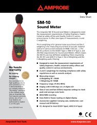
➊ Transformer Jaws: Designed to pick up the AC current<br />
flowing through the conductor.<br />
➋ Jaw Opening Lever: Press lever to open transformer jaws.<br />
When pressure on lever is released, the jaws will close again.<br />
➌ Selector Switch: Turns instrument on and off and selects the<br />
measuring function.<br />
➍ AC/DC selector switch (<strong>AC40C</strong>): With the selector switch set<br />
to voltage measurement, this button selects between AC<br />
and DC voltage.<br />
➎ Data Hold Switch: Holds reading for all functions and<br />
ranges. Press again to release HOLD before taking a new<br />
measurement.<br />
➏ Digital Display: 3-3/4 digit LCD (max reading 3999) with<br />
decimal point, low battery N, Auto-range, Data Hold l,<br />
and unit indicators, plus, for the AC meter: ACB, DCF,<br />
Polarity — ) and continuity R.<br />
➐ Input Terminals (AC meters): Connect the black test lead<br />
to the “COM” input and red lead to the “+” input when<br />
measuring voltage, resistance and continuity (<strong>AC40C</strong>).<br />
3
<strong>AC40C</strong> / <strong>AD40B</strong><br />
Mini Clamp Meters<br />
Contents<br />
Symbols............................................................................................. 5<br />
Warnings and Precautions.................................................... 5<br />
Introduction..................................................................................... 6<br />
Unpacking and Inspection......................................................... 6<br />
AC Current Measurement (Fig. 1)................................................... 6<br />
AC & DC Voltage Measurement (<strong>AC40C</strong>) (Fig. 2)........................... 7<br />
Resistance & Continuity Measurement (<strong>AC40C</strong>) (Fig. 3)................ 7<br />
Display Hold..................................................................................... 7<br />
Specifications................................................................................... 7<br />
Troubleshooting & Maintenance.................................................. 10<br />
Battery Replacement................................................................ 10<br />
4
Symbols<br />
Battery <br />
<br />
Double<br />
insulated<br />
<br />
Refer to the<br />
manual<br />
Dangerous<br />
Voltage<br />
Direct Current Earth Ground<br />
<br />
Alternating<br />
Current Audible tone<br />
<br />
Complies with<br />
EU directives<br />
<br />
Application<br />
around and<br />
removal from<br />
hazardous live<br />
conductors is<br />
permitted<br />
Warnings and Precautions<br />
• This instrument is EN61010-1:2001 and EN61010-2-32<br />
certified for Installation Category III. It is recommended for<br />
use with local level power distribution, appliances, portable<br />
equipment, etc, where only smaller transient overvoltages<br />
may occur, and not for primary supply lines, overhead lines<br />
and cable systems.<br />
• This instrument must not be used on uninsulated conductors<br />
at a voltage greater than 600V ac/dc.<br />
• Use extreme caution when working around bare conductors<br />
and bus bars.<br />
• Do not exceed the instrument overload limits per function<br />
(see specifications) nor the limits marked on the instrument.<br />
• Exercise extreme caution when: measuring voltage >60 V<br />
DC or 30 V AC RMS // current >10 mA // AC power lines with<br />
inductive loads // AC power lines during electrical storms //<br />
servicing CRT equipment. High voltages can be lethal and<br />
high voltage transients may occur at any time.<br />
• Never measure current while test leads are inserted in the<br />
input jacks.<br />
• Always inspect your instrument, test leads and accessories for<br />
signs of damage or abnormality before every use. If abnormal<br />
conditions exist (broken or damaged test leads, cracked case,<br />
display not reading, etc.), do not use.<br />
• When making voltage measurements, make sure these<br />
ranges function correctly. Take a reading of a known voltage<br />
first.<br />
5
• Never ground yourself when taking measurements. Do not<br />
touch exposed metal pipes, outlets, fixtures, etc., which<br />
might be at ground potential. Keep your body isolated from<br />
ground and never touch exposed wiring, connections, test<br />
probe tips, or any live circuit conductors.<br />
• Do not operate the instrument in an explosive atmosphere<br />
(flammable gases, fumes, vapor, dust).<br />
• Do not use this or any piece of test equipment without<br />
proper training. Read the operating instructions before use<br />
and follow all safety instructions.<br />
• Use the meter only as specified in this manual; otherwise the<br />
meters safety circuitry may not protect you.<br />
• Use extreme caution when working around bare conductors.<br />
Contact with the conductor could result in electric shock.<br />
• The ridge at the top of the clamp body is intended to keep<br />
hands and fingers away from hazardous live conductors.<br />
Introduction<br />
The <strong>AD40B</strong> is an average sensing and RMS (sine wave) indicating<br />
AC current clamp. The <strong>AC40C</strong> is an average sensing and RMS<br />
(sine wave) indicating AC current clamp meter that also<br />
measures AC and DC voltage, resistance and continuity.<br />
Unpacking and Inspection<br />
Your shipping carton should include the digital clamp meter ,<br />
a carrying case, two 1.5 V AAA (UM-2) batteries (installed), and<br />
this manual plus one test lead set (one black, one red) for the<br />
<strong>AC40C</strong> meter. If any of the items are damaged or missing, return<br />
the complete package to the place of purchase for an exchange.<br />
AC Current Measurement (Fig. 1)<br />
1. Set the slide switch to ACB position.<br />
2. Open spring-loaded clamp by pressing lever on left side of<br />
meter.<br />
3. Position clamp around wire or conductor and release clamp<br />
lever. Make sure that the conductor is centered in the clamp<br />
and that the clamp is entirely closed. The clamp must be<br />
positioned around only one conductor. If it is placed around<br />
two or more current carrying conductors, the reading is<br />
FALSE.<br />
4. Read the measured value on the display. If the measured<br />
value exceeds the highest range for a period of time,<br />
overheating may occur. Interrupt measurement.<br />
6
Note<br />
Do not measure current on high-voltage conductors (>600 V) in<br />
order to avoid risk of discharge and/or incorrect reading.<br />
AC & DC Voltage Measurement (<strong>AC40C</strong>) (Fig. 2)<br />
1. Connect the black test lead to the COM input and the red<br />
test lead to the “+” input.<br />
2. Set the selector switch to V C position.<br />
3. Press the AC DC button to select AC or DC voltage ( B or F is<br />
displayed).<br />
4. Connect probe tips to circuit, in parallel to the load.<br />
5. Read the measured value on the display.<br />
Resistance & Continuity Measurement (<strong>AC40C</strong>) (Fig. 3)<br />
1. Remove any voltage from resistance to be measured and<br />
discharge all capacitors.<br />
2. Connect the black test lead to the COM input and the red<br />
test lead to the “+” input.<br />
3. Set the selector switch to Ω R position.<br />
4. Connect the probe tips across the circuit or resistance.<br />
5. Read the measured value on the display.<br />
The instrument emits a continuous tone and the R symbol is<br />
displayed when the measured resistance is < 40 Ω.<br />
Display Hold<br />
Press the HOLD button to keep the measured value on the<br />
display for later viewing. Press HOLD again to release the<br />
“Display Hold” function before taking a new measurement.<br />
Display Hold can be applied to all measuring functions.<br />
Specifications<br />
General Specifications<br />
Display: (<strong>AC40C</strong> & <strong>AD40B</strong>) 3-3/4 digit LCD (max. reading 3999).<br />
Polarity Indication: Automatic, negative indicated, positive<br />
implied<br />
Overrange Indication: “OL” indicated.<br />
Measuring Principle: Dual slope integration.<br />
Range Selection: Automatic.<br />
Low Battery Indication: N when battery voltage falls below<br />
operating voltage.<br />
7
Auto Power Off (APO): Approx. 30 minutes after no function<br />
change.<br />
Environmental Conditions<br />
This instrument is designed for indoor use.<br />
Altitude: < 2000 m<br />
Operating Temperature: 0 °C to +40 °C (32˚F to 104˚F),<br />
Input Impedance: 1 MΩ<br />
Overload Protection: 600 V rms<br />
AC Voltage (<strong>AC40C</strong>)<br />
Range Accuracy (40 – 450 Hz) Resolution<br />
400 V ±(1.5 %rdg +10 dgt)<br />
50-60Hz;(+/-3% rdg + 15dgts) 400Hz<br />
0.1 V<br />
600 V ±(1.5 %rdg +10 dgt)<br />
1 V<br />
50-60Hz;(+/-3% rdg + 15dgts) 400Hz<br />
Input Impedance: 1 MΩ<br />
Measuring method: Dual slope integration. Average Sensing,<br />
rms indication. Overload Protection: 600 V rms<br />
AC Current (<strong>AC40C</strong>/<strong>AD40B</strong>)<br />
Range Frequency Accuracy Resolution<br />
40A 50/60 Hz ±(2.5%rdg +10dgt) 0.01A<br />
40A 60 – 400 Hz ±(4.0%rdg +10dgt) 0.01A<br />
400A 50/60 Hz ±(2.5%rdg +10dgt) 0.1A<br />
400A 60 – 400 Hz ±(4.0%rdg +10dgt) 0.1A<br />
Overload Protection: 660 A<br />
Accuracies are specified for conductor centered in the jaw. If<br />
the conductor is not centered, an additional error of max 1.5%<br />
can result.<br />
Measuring method: Dual slope integration. Average Sensing,<br />
rms indication.<br />
Resistance (<strong>AC40C</strong>)<br />
Range Accuracy Resolution<br />
400 Ω ±(1.0 %rdg + 5 dgt) 0.1 Ω<br />
Max open circuit voltage, <strong>AC40C</strong>: -1.2 V nominal<br />
Overload Protection, <strong>AC40C</strong>: 600 Vrms<br />
9
Audible Continuity (<strong>AC40C</strong>)<br />
Like resistance measurement. Continuous tone and R display at<br />
R ≤40 Ω for <strong>AC40C</strong><br />
Max open circuit voltage: -1.2 V<br />
Overload Protection: 600 Vrms<br />
Data Hold: Hold display reading for all functions and ranges.<br />
Always remember to release Data Hold when taking a new<br />
measurement.<br />
Troubleshooting & Maintenance<br />
In case of malfunction during the operation of the meter, the<br />
following steps should be performed in order to isolate the<br />
cause of the problem:<br />
1. Check the batteries.<br />
2. Review the operating instructions for possible mistakes in<br />
operating procedure.<br />
3. Check clamp against a known current source.<br />
4. Check test leads for continuity (voltage and resistance).<br />
Except for the replacement of the batteries, repair of the clamp<br />
should be performed only by a Factory Authorized Service<br />
Center or by other qualified instrument service personnel.<br />
Front panel and case can be cleaned with a mild solution of<br />
detergent and water. Apply sparingly with a soft cloth and let<br />
dry completely before using. Do not use aromatic hydrocarbons<br />
or chlorinated solvents for cleaning.<br />
Battery Replacement<br />
The meter is powered by two 1.5 V AAA batteries. Replace<br />
batteries as soon as N symbol is displayed.<br />
1. Turn meter off. Disconnect and remove the test leads.<br />
2. Position the meter face down. Remove the two screws and<br />
lift off rear case.<br />
3. Replace the batteries.<br />
4. Reassemble the case.<br />
10
<strong>AC40C</strong><br />
<strong>AD40B</strong><br />
Mini Clamp Meters<br />
Français<br />
Mode d’emploi<br />
<strong>AC40C</strong>_Rev001<br />
© 2009 <strong>Amprobe</strong> Test Tools.<br />
Tous droits réservés.<br />
11
Limites de garantie et de responsabilité<br />
<strong>Amprobe</strong> garantit l’absence de vices de matériaux et de fabrication de ce produit<br />
pendant une période d’un an prenant effet à la date d’achat. Cette garantie ne<br />
s’applique pas aux fusibles, aux piles jetables ni à tout produit mal utilisé, modifié,<br />
contaminé, négligé ou endommagé par accident ou soumis à des conditions anormales<br />
d’utilisation et de manipulation. L’obligation de garantie d’<strong>Amprobe</strong> est limitée, au<br />
choix d’<strong>Amprobe</strong>, au remboursement du prix d’achat ou à la réparation/remplacement<br />
gratuit d’un produit défectueux. Les distributeurs agréés par <strong>Amprobe</strong> ne sont pas<br />
autorisés à appliquer une garantie plus étendue au nom d’<strong>Amprobe</strong>. Pour bénéficier<br />
de la garantie, renvoyez le produit accompagné d’un justificatif d’achat auprès d’un<br />
centre de services agréé par <strong>Amprobe</strong> Test Tools ou d’un distributeur ou d’un revendeur<br />
<strong>Amprobe</strong>. Voir la section Réparation pour tous les détails. La présente garantie est<br />
le seul et exclusif recours toutes autres garanties, explicites, implicites ou statutaires,<br />
notamment le cas échéant les garanties de qualité marchande ou d’adaptation a un<br />
objectif particulier sont exclues par les présentes. <strong>Amprobe</strong>, la société mère ou ses<br />
filiales ne peuvent en aucun cas être tenues responsables des dommages particuliers,<br />
indirects, accidentels ou consécutifs, ni d’aucuns dégâts ou pertes de données, sur une<br />
base contractuelle, extra-contractuelle ou autre. Etant donné que certaines juridictions<br />
n’admettent pas les limitations d’une condition de garantie implicite, ou l’exclusion ou<br />
la limitation de dégâts accidentels ou consécutifs, il se peut que les limitations et/ou les<br />
exclusions de cette garantie ne s’appliquent pas à votre cas.<br />
Réparation<br />
Tous les outils de test renvoyés pour un étalonnage ou une réparation couverte ou<br />
non par la garantie doivent être accompagnés des éléments suivants : nom, raison<br />
sociale, adresse, numéro de téléphone et justificatif d’achat. Ajoutez également une<br />
brève description du problème ou du service demandé et incluez les cordons de mesure<br />
avec l’appareil. Les frais de remplacement ou de réparation hors garantie doivent être<br />
acquittés par chèque, mandat, carte de crédit avec date d’expiration, ou par bon de<br />
commande payable à l’ordre de <strong>Amprobe</strong>® Test Tools.<br />
Remplacements et réparations sous garantie – Tous pays<br />
Veuillez lire la déclaration de garantie et vérifier la pile avant de demander une<br />
réparation. Pendant la période de garantie, tout outil de test défectueux peut être<br />
renvoyé auprès de votre distributeur <strong>Amprobe</strong>® Test Tools pour être échangé contre un<br />
produit identique ou similaire. Consultez la section « Where to Buy » sur le site www.<br />
amprobe.com pour obtenir la liste des distributeurs dans votre région. Au Canada et<br />
aux Etats-Unis, les appareils devant être remplacés ou réparés sous garantie peuvent<br />
également être envoyés dans un centre de services <strong>Amprobe</strong>® Test Tools (voir les<br />
adresses ci-dessous).<br />
Remplacements et réparations hors garantie – Canada et Etats-Unis<br />
Les appareils à réparer hors garantie au Canada et aux Etats-Unis doivent être envoyés<br />
dans un centre de services <strong>Amprobe</strong>® Test Tools. Appelez <strong>Amprobe</strong>® Test Tools ou<br />
renseignez-vous auprès de votre lieu d’achat pour connaître les tarifs en vigueur de<br />
remplacement ou de réparation.<br />
Aux Etats-Unis<br />
Au Canada<br />
<strong>Amprobe</strong> Test Tools<br />
<strong>Amprobe</strong> Test Tools<br />
Everett, WA 98203 E-U Mississauga, ON L4Z 1X9 Canada<br />
Tel: 877-993-5853 Tel: 905-890-7600<br />
Fax: 425-446-6390 Fax: 905-890-6866<br />
Remplacements et réparations hors garantie – Europe<br />
Les appareils européens non couverts par la garantie peuvent être remplacés par votre<br />
distributeur <strong>Amprobe</strong>® Test Tools pour une somme nominale. Consultez la section «<br />
Where to Buy » sur le site www.amprobe.com pour obtenir la liste des distributeurs<br />
dans votre région.<br />
Adresse postale européenne*<br />
<strong>Amprobe</strong>® Test Tools Europe<br />
Beha-<strong>Amprobe</strong> GmbH<br />
In den Engematten 14<br />
79286 Glottertal, Germany<br />
Tel.: +49 (0) 7684 8009 – 0<br />
*(Réservée à la correspondance – Aucune réparation ou remplacement n’est possible à<br />
cette adresse. Nos clients européens doivent contacter leur distributeur.)<br />
12
0 10 20 30 40<br />
0 10 20 30 40<br />
1<br />
CAT III<br />
600V<br />
5<br />
CAT III<br />
600V<br />
4<br />
HOLD<br />
HOLD<br />
AC<br />
DC<br />
2<br />
A<br />
A<br />
2<br />
3<br />
CAT 600V<br />
400A MAX<br />
COM 600V<br />
MAX<br />
6<br />
CAT<br />
400A<br />
600V<br />
MAX<br />
<strong>AC40C</strong><br />
7<br />
<strong>AD40B</strong><br />
➊ Pince: Capte le courant qui passe par le conducteur.<br />
➋ Levier de la Pince: Poussez ce levier pour ouvrir la pince. La<br />
pince ferme quand la pression est relachée.<br />
➌ Sélecteur de Fonctions: Allume et éteint l’appareil et<br />
sélectionne la fonction de mesure.<br />
➍ Sélecteur CC/CA: Avec le sélecteur de fonctions mis sur<br />
mesure de tension, cette touche choisit entre Tension CC et<br />
Tension CA.<br />
➎ Bouton Data Hold: Maintient la lecture pour toutes<br />
fonctions et gammes.<br />
➏ Affichage Digital: LCD 3-3/4 digits (lecture max 3999)<br />
avec indicateurs de point décimal, de pile déchargée ,<br />
sélection automatique, Data Hold et unités, plus, pour les<br />
instrument AC: AC, DC, polarité, et continuité .<br />
➐ Entrées: Pour les mesures de tension, de résistance et de<br />
continuité, connectez toujours le cordon de mesure noir à<br />
l’entrée COM, et le rouge à l’entrée “+” (<strong>AC40C</strong>).<br />
13
<strong>AC40C</strong> / <strong>AD40B</strong><br />
Mini Clamp Meters<br />
Symboles......................................................................................... 15<br />
Avertissements et Précautions............................................ 15<br />
Introduction................................................................................... 16<br />
Désemballage et inspection..................................................... 16<br />
Mesure de Courant Alternatif (fig. 1)........................................... 16<br />
Mesure de Tension Continue et Alternative (<strong>AC40C</strong>) (fig. 2)...... 17<br />
Mesure de Résistance et de Continuité (<strong>AC40C</strong>) (fig. 3).............. 17<br />
Maintien d’Affichage.................................................................... 17<br />
Spécifications................................................................................. 17<br />
Dépannage et Maintenance......................................................... 20<br />
Remplacement de la Pile.......................................................... 20<br />
14
Symboles<br />
N Pile <br />
Double isolation <br />
Se reporter au<br />
mode d’emploi<br />
Tension<br />
dangereuse<br />
Courant continu Prise de terre<br />
<br />
Courant<br />
alternatif Signal sonore<br />
<br />
Conforme aux<br />
directives de l’UE<br />
<br />
Son application<br />
et son retrait<br />
à proximité de<br />
conducteurs<br />
sous tension<br />
dangereuse<br />
sont autorisés.<br />
Avertissements et Précautions<br />
• Cet instrument est certifié EN61010-1 :2001 et EN61010-2-32<br />
catégorie d’installation III. Son utilisation est recommandée<br />
pour le niveau de distribution local, appareils ménagers,<br />
appareils portatifs, etc, où les surtenstions transitoires son<br />
limitées, et non pour les installations de puissance et lignes<br />
de transmission et câblages à haute tension.<br />
• N’utilisez pas cet appareil avec des conducteurs non-isolés à<br />
des tensions supérieures à 600 V ca/cc.<br />
• Soyez très prudent quand vous mesurez sur des câbles nonisolés<br />
et des rails de distribution.<br />
• N’excédez jamais les limites de surcharge continues par<br />
fonction (voir spécifications) ou d’autres limites marquées sur<br />
l’appareil.<br />
• Soyez très prudent quand vous mesurez des tensions >60 V<br />
CC ou 30 V CA, ou des courants >10 mA // tension ou courant<br />
de secteur avec charge inductive ou par temps de tempête<br />
// dans des appareils à tube cathodique (transitoires à haute<br />
tension).<br />
• Ne mesurez jamais du courant avec les cordons insérés dans<br />
l’appareil.<br />
• Inspectez appareil, câbles, connecteurs avant chaque mesure.<br />
N’utilisez pas des pièces endommagées.<br />
• Ne touchez pas les pointes de touche ou le circuit pendant les<br />
mesures. Isolezvous.<br />
15
• N’utilisez pas cet appareil dans des atmosphères explosives.<br />
• N’utilisez pas cet appareil sans formation adéquate. Lisez<br />
le mode d’emploi avant l’utilisation et suivez les conseils de<br />
sécurité.<br />
• Utiliser l’appareil en respectant les consignes de sécurité de<br />
ce manuel afin de ne pas entraver les circuits de sécurité et la<br />
protection de l’utilisateur.<br />
• Faire preuve d’extrême prudence en travaillant à proximité<br />
des conducteurs nus Tout contact avec le conducteur pourrait<br />
entraîner une électrocution.<br />
• La collerette au sommet de la pince ampèremétrique est<br />
destinée à protéger les mains et les doigts des conducteurs<br />
sous tension dangereuse.<br />
Introduction<br />
Le <strong>AD40B</strong> est des pinces de courant CA à mesure moyenne et<br />
indication de valeur efficace (onde sinusoïdale). Le <strong>AC40C</strong> est des<br />
pinces de courant CA à mesure moyenne et indication de valeur<br />
efficace (onde sinusoïdale), qui mesurent également les tensions<br />
CC et CA, la résistance et la continuité.<br />
Désemballage et inspection<br />
Votre emballage devrait contenir: un multimètre-pince,<br />
une sacoche, deux piles-1.5 V AAA (UM-2) (dans l’appareil)<br />
et ce manuel, plus, pour l’instrument <strong>AC40C</strong>, une paire de<br />
cordons de test (un noir, un rouge). Si une pièce manque ou<br />
est endommagée, retournez à votre point de vente pour un<br />
échange.<br />
Mesure de Courant Alternatif (fig. 1)<br />
1. Placez le sélecteur sur ACB.<br />
2. Ouvrez la pince en poussant sur le levier.<br />
3. Placez la pince autour du conducteur et fermez la<br />
(en relachant le levier). Assurez-vous que la pince est<br />
complètement fermée et qu’elle ne contient qu’un seul<br />
conducteur. Si elle en contient plusieurs, la mesure est<br />
faussée.<br />
4. Lisez la valeur affichée. Si la valeur mésurée dépasse<br />
la gamme la plus élevée, l’appareil peur surchauffer.<br />
Interrompez la mesure.<br />
Note<br />
Ne mesurez pas des courants sur des lignes de haute tension<br />
(>600 V) afin d’éviter des chocs électriques et/ou des mesures<br />
erronnées.<br />
16
Mesure de Tension Continue et Alternative (<strong>AC40C</strong>)<br />
(fig. 2)<br />
1. Connectez le cordon noir à l’entrée COM et le rouge à<br />
l’entrée “+”.<br />
2. Placez le sélecteur sur V C.<br />
3. Pressez le bouton(insert AC/DC key cap) pour sélectionner<br />
la mesure de tension alternative ou continue (B ou F est<br />
affiché).<br />
4. Connectez les pointes de touche au circuit (en parallèle avec<br />
la source de tension).<br />
5. Lisez la valeur affichée.<br />
Mesure de Résistance et de Continuité (<strong>AC40C</strong>) (fig. 3)<br />
1. Coupez l’alimentation du circuit à mesurer et déchargez les<br />
condensateurs.<br />
2. Connectez le cordon noir à l’entrée COM et le rouge à<br />
l’entrée “+”.<br />
3. Placez le sélecteur sur Ω R.<br />
4. Connectez les pointes de touche au circuit.<br />
5. Lisez la valeur affichée.<br />
Un signal sonore retentit et est affiché quand R < 40 Ω.<br />
Maintien d’Affichage<br />
Presser la touche HOLD maintient l’affichage pour visualisation<br />
ultérieure. Pressez HOLD à nouveau avant de prendre une<br />
nouvelle mesure afin de libérer l’affichage. HOLD peut être<br />
appliqué à toutes les fonctions de mesure.<br />
Spécifications<br />
Spécifications Générales<br />
Afficheur: (<strong>AC40C</strong> & <strong>AD40B</strong>) LCD 3-3/4 digits (lecture max. 3999).<br />
Indication de polarité: automatique; négative indiquée, positive<br />
sous-entendue<br />
Indication de Dépassement de Calibre: “OL”.<br />
Méthode de mesure: intégration à double rampe.<br />
Sélection de gammes: automatique.<br />
Indication de pile déchargée: N, quand la tension tombe endessous<br />
du niveau de fonctionnement.<br />
Coupure automatique (APO) : Après environ 30 minutes<br />
d’inactivité.<br />
17
Conditions d’Environnement<br />
Cet instrument est conçu pour utilisation à l’intérieur<br />
Altitude: < 2000 m<br />
Température d’utilisation: 0 °C à +40 °C (32˚F to 104˚F),<br />
Tension Continue (<strong>AC40C</strong>)<br />
Gamme Précision Résolution<br />
400 V ±(1.0 %lect +5 dgt) 0.1 V<br />
600 V ±(1.0 %lect +5 dgt) 1 V<br />
Impédance d’entrée: 1 MΩ<br />
Protection de surcharge: 600 V rms<br />
Tension Alternative (<strong>AC40C</strong>)<br />
Gamme Précision (40 – 450 Hz) Résolution<br />
400 V ±(1.5 %lect +10 dgt)<br />
50-60Hz;(+/-3% rdg + 15dgts) 400Hz<br />
0.1 V<br />
600 V ±(1.5 %lect +10 dgt)<br />
1 V<br />
50-60Hz;(+/-3% rdg + 15dgts) 400Hz<br />
Impédance d’entrée: 1 MΩ<br />
Méthode de mesure: Intégration à double rampe.<br />
Mesure de la valeur moyenne; affichage de la valeur efficace<br />
(onde sinusoïdale).<br />
Protection de surcharge: 600 V rms<br />
Courant Alternatif (<strong>AC40C</strong>/<strong>AD40B</strong>)<br />
Gamme Fréquence Précision Résolution<br />
40A 50/60 Hz ±(2.5%lect +10dgt) 0.01A<br />
40A 60 – 400 Hz ±(4.0%lect +10dgt) 0.01A<br />
400A 50/60 Hz ±(2.5%lect +10dgt) 0.1A<br />
400A 60 – 400 Hz ±(4.0%lect +10dgt) 0.1A<br />
Protection de surcharge: 660 A<br />
La précision donnée s’applique pour le conducteur centré<br />
dans la pince. Si le conducteur n’est pas centré, une erreur<br />
supplémentaire de 1.5 % peut en résulter.<br />
Méthode de mesure: Intégration à double rampe. Mesure<br />
de la valeur moyenne; affichage de la valeur efficace (onde<br />
sinusoïdale)<br />
19
Résistance (Sélection Automatique) (<strong>AC40C</strong>)<br />
Gamme Précision Résolution<br />
400 Ω ±(1.0 %lect + 5 dgt) 0.1 Ω<br />
Tension en circuit ouvert, <strong>AC40C</strong>: -1.2 V nominal<br />
Protection de surcharge, <strong>AC40C</strong>: 600 Vrms<br />
Indication de Continuité (<strong>AC40C</strong>)<br />
Indication sonore et affichage de à R ≤40 Ωpour <strong>AC40C</strong>.<br />
Tension en circuit ouvert, <strong>AC40C</strong>: -1.2 V nominal<br />
Protection de surcharge, <strong>AC40C</strong>: 600 Vrms<br />
Maintien d’Affichage: Pressez HOLD pour maintenir l’affichage<br />
pour toutes les fonctions et gammes. Pressez HOLD à nouveau<br />
pour désactiver la fonction avant de pour une nouvelle mesure.<br />
Dépannage et Maintenance<br />
En cas de problèmes:<br />
1. Vérifiez le chargement de la pile.<br />
2. Vérifiez le mode d’emploi.<br />
3. Mesurez une valeur de courant connue.<br />
4. Vérifiez les câbles de mesure (tension et résistance).<br />
A part le remplacement de la pile, toute réparation ne doit être<br />
effectuée que par un centre de services agréé par Wavetek.<br />
Le boîtier peut être nettoyé avec une savonnée douce. Laissez<br />
secher complètement avant utilisation.<br />
Remplacement de la Pile<br />
1. L’instrument est alimenté par deux piles de 1.5 V AAA.<br />
Remplacez les piles dès que est affiché.<br />
2. Coupez l’alimentaton de l’appareil et enlevez les cordons.<br />
3. Dévissez et enlevez le boîtier arrière.<br />
4. Remplacez les piles et réassemblez le boîtier.<br />
20
<strong>AC40C</strong><br />
<strong>AD40B</strong><br />
Mini Clamp Meters<br />
Deutsch<br />
Bedienungshandbuch<br />
<strong>AC40C</strong>_Rev001<br />
© 2009 <strong>Amprobe</strong> Test Tools.<br />
Alle Rechte vorbehalten.<br />
21
Beschränkte Gewährleistung und<br />
Haftungsbeschränkung<br />
Es wird gewährleistet, dass dieses <strong>Amprobe</strong>-Produkt für die Dauer von einem Jahr ab<br />
dem Kaufdatum frei von Material- und Fertigungsdefekten ist. Diese Gewährleistung<br />
erstreckt sich nicht auf Sicherungen, Einwegbatterien oder Schäden durch Unfälle,<br />
Nachlässigkeit, Missbrauch, Änderungen oder abnormale Betriebsbedingungen bzw.<br />
unsachgemäße Handhabung. Die Garantieverpflichtung von <strong>Amprobe</strong> beschränkt<br />
sich darauf, dass <strong>Amprobe</strong> nach eigenem Ermessen den Kaufpreis ersetzt oder aber<br />
das defekte Produkt unentgeltlich repariert oder austauscht. Die Verkaufsstellen sind<br />
nicht dazu berechtigt, diese Gewährleistung im Namen von <strong>Amprobe</strong> zu erweitern. Um<br />
während der Gewährleistungsperiode Serviceleistungen zu beanspruchen, das Produkt<br />
mit Kaufnachweis an ein autorisiertes <strong>Amprobe</strong> Test Tools Service-Center oder an einen<br />
<strong>Amprobe</strong>-Fachhändler/-Distributor einsenden. Nähere Einzelheiten siehe Abschnitt<br />
„Reparatur“. Diese Gewährleistung stellt den einzigen und alleinigen Rechtsanspruch<br />
auf Schadenersatz dar. Alle anderen Gewährleistungen, vertraglich geregelte oder<br />
gesetzlich vorgeschriebene, einschließlich der gesetzlichen Gewährleistung der<br />
Marktfähigkeit und der Eignung für einen bestimmten Zweck, werden abgelehnt.<br />
Weder <strong>Amprobe</strong> noch dessen Muttergesellschaft oder Tochtergesellschaften<br />
übernehmen Haftung für spezielle, indirekte, Neben- oder Folgeschäden oder für<br />
Verluste, die auf beliebiger Ursache oder Rechtstheorie beruhen. Weil einige Staaten<br />
oder Länder den Ausschluss oder die Einschränkung einer implizierten Gewährleistung<br />
sowie den Ausschluss von Begleit- oder Folgeschäden nicht zulassen, ist diese<br />
Gewährleistungsbeschränkung möglicherweise für Sie nicht gültig.<br />
Reparatur<br />
Alle Geräten, die innerhalb oder außerhalb des Garantiezeitraums zur Reparatur<br />
oder Kalibrierung eingesendet werden, müssen mit folgenden Informationen<br />
und Dokumenten versehen werden: Name des Kunden, Firmenname, Adresse,<br />
Telefonnummer und Kaufbeleg. Zusätzlich bitte dem Messgerät eine kurze Beschreibung<br />
des Problems oder der gewünschten Wartung sowie die Messleitungen beilegen. Die<br />
Gebühren für Reparaturen außerhalb der Garantie oder für den Ersatz von Instrumenten<br />
müssen per Scheck, Geldanweisung oder Kreditkarte (Kreditkartennummer mit<br />
Ablaufdatum) beglichen werden oder es muss ein Auftrag an <strong>Amprobe</strong>® Test Tools<br />
formuliert werden.<br />
Garantiereparaturen und -austausch - alle Länder<br />
Bitte die Garantieerklärung lesen und die Batterie prüfen, bevor Reparaturen<br />
angefordert werden. Während der Garantieperiode können alle defekten Geräte zum<br />
Umtausch gegen dasselbe oder ein ähnliches Produkt an den <strong>Amprobe</strong>® Test Tools-<br />
Distributor gesendet werden. Ein Verzeichnis der zuständigen Distributoren ist im<br />
Abschnitt „Where to Buy“ (Verkaufsstellen) auf der Website www.amprobe.com zu<br />
finden. Darüber hinaus können in den USA und in Kanada Geräte an ein <strong>Amprobe</strong>® Test<br />
Tools Service-Center (Adresse siehe weiter unten) zur Reparatur oder zum Umtausch<br />
eingesendet werden.<br />
Reparaturen und Ersatz außerhalb des Garantiezeitraums - USA und Kanada<br />
Für Reparaturen außerhalb des Garantiezeitraums in den Vereinigten Staaten und<br />
in Kanada werden die Geräte an ein <strong>Amprobe</strong>® Test Tools Service-Center gesendet.<br />
Auskunft über die derzeit geltenden Reparatur- und Austauschgebühren erhalten Sie<br />
von <strong>Amprobe</strong>® Test Tools oder der Verkaufsstelle.<br />
In den USA:<br />
In Kanada:<br />
<strong>Amprobe</strong> Test Tools<br />
<strong>Amprobe</strong> Test Tools<br />
Everett, WA 98203 USA Mississauga, ON L4Z 1X9 Kanada<br />
Tel.: 877-993-5853 Tel.: 905-890-7600<br />
Fax: 425-446-6390 Fax: 905-890-6866<br />
Reparaturen und Austausch außerhalb des Garantiezeitraums - Europa<br />
Geräte mit abgelaufener Garantie können durch den zuständigen <strong>Amprobe</strong>® Test<br />
Tools-Distributor gegen eine Gebühr ersetzt werden. Ein Verzeichnis der zuständigen<br />
Distributoren ist im Abschnitt „Where to Buy“ (Verkaufsstellen) auf der Website www.<br />
amprobe.com zu finden.<br />
Korrespondenzanschrift für Europa*<br />
<strong>Amprobe</strong>® Test Tools Europe<br />
Beha-<strong>Amprobe</strong> GmbH<br />
In den Engematten 14<br />
79286 Glottertal, Deutschland<br />
Tel.: +49 (0) 7684 8009 – 0<br />
*(Nur Korrespondenz – keine Reparaturen und kein Umtausch unter dieser Anschrift.<br />
Kunden in Europa wenden sich an den zuständigen Distributor.)<br />
22
0 10 20 30 40<br />
0 10 20 30 40<br />
1<br />
CAT III<br />
600V<br />
5<br />
CAT III<br />
600V<br />
4<br />
HOLD<br />
HOLD<br />
AC<br />
DC<br />
2<br />
A<br />
A<br />
2<br />
3<br />
CAT 600V<br />
400A MAX<br />
COM 600V<br />
MAX<br />
6<br />
CAT<br />
400A<br />
600V<br />
MAX<br />
<strong>AC40C</strong><br />
7<br />
<strong>AD40B</strong><br />
➊ Stromzange: Überträgt den Strom der durch den Leiter fließt.<br />
➋ Zangenhebel: Hebel drücken um Zange zu öffnen. Zange<br />
schließt beim Loslassen des Hebels.<br />
➌ Funktionsschalter: Schaltet Gerät ein und aus und wählt die<br />
Meßfunktion.<br />
➍ AC/DC Schalter (<strong>AC40C</strong>): Mit dem Funktionsschalter auf<br />
Spannungsmessung, wählt dieser Schalter zwischen Gleichund<br />
Wechselspannung.<br />
➎ Data Hold Taste: Friert die Anzeige für alle Bereiche und<br />
Funktionen. HOLD Taste immer lösen bevor Sie eine neue<br />
Messung vornehmen.<br />
➏ Digitale Anzeige: 3-3/4 Digit LCD (max Ablesung 3999) mit<br />
Dezimalpunkt-, Entladene Batterie- , Auto-Bereich, Data<br />
Hold- , und Einheitsanzeigen, plus, für AC meter: AC,<br />
DC, Polarität- und Durchgangs- Anzeigen.<br />
➐ Eingänge (AC Meter): Das schwarze Meßkabel für<br />
Spannungs-, Widerstandsund Durchgangsmessung immer mit<br />
COM Eingang und rotes immer mit “+” Eingang verbinden<br />
(<strong>AC40C</strong>).<br />
23
<strong>AC40C</strong> / <strong>AD40B</strong><br />
Mini Clamp Meters<br />
Symbole.......................................................................................... 25<br />
Warnungen und Vorsichtsmaßnahmen............................. 25<br />
Einleitung....................................................................................... 26<br />
Auspacken................................................................................. 26<br />
Wechselstrommessung (Fig. 1)...................................................... 26<br />
Gleich- und Wechselspannungsmessung (<strong>AC40C</strong>) (Fig. 2)........... 26<br />
Widerstands- und Durchgangsmessung (<strong>AC40C</strong>) (Fig. 3)............ 27<br />
Anzeigesperre................................................................................ 27<br />
Spezifikationen.............................................................................. 27<br />
Fehlersuche und Wartung............................................................. 30<br />
Batteriewechsel........................................................................ 30<br />
24
Symbole<br />
Batterie <br />
Schutzisoliert <br />
Im Handbuch<br />
nachlesen<br />
Gefährliche<br />
Spannung<br />
Gleichstrom Erde, Masse<br />
Wechselstrom Akustischer Alarm<br />
<br />
Übereinstimmung<br />
mit EU-Richtlinien<br />
<br />
Anwendung in<br />
der Umgebung<br />
von gefährlichen<br />
stromführenden<br />
Leitern zulässig<br />
Warnungen und Vorsichtsmaßnahmen<br />
• Dieses Gerät ist EN61010-1:2001 und EN61010-2-32 zertifiziert<br />
für Installationsklasse III. Anwendung ist empfohlen auf<br />
lokaler Verteilerebene, mit Elektrogeräten, tragbaren<br />
Geräten, usw, wo nur kleinere Überspannungsspitzen<br />
auftreten können, jedoch nicht für Starkstromnetze und<br />
Hochspannungsanlagen<br />
• Dieses Gerät darf nicht mit nichtisolierten Leitern bei<br />
Spannungen höher als 600 V AC/DC verwendet werden<br />
• Seien Sie äußerst vorsichtig wenn Sie an nicht-isolierten<br />
Leitern und Stromschienen messen<br />
• Überschreiten Sie nie die kontinuierlichen Überlastgrenzen<br />
der verschiedenen Meßfunktionen (siehe Spezifikationen)<br />
oder andere Grenzen welche auf dem Gerät markiert sind<br />
• Vorsicht beim Messen von Spannungen >60 V DC oder 30 V<br />
AC// Strömen >10 mA // Netzstrom/-spannung bei induktiever<br />
Last oder bei Gewittern // beim Messen an Bildröhrgeräten<br />
(hohe Spannungsspitzen)<br />
• Keine Strommessung vornehmen mit eingesteckten<br />
Meßkabeln<br />
• Unsersuchen Sie Gerät, Meßkabel, Verbinder, usw. vor jeder<br />
Messung. Beschädigte Teile nicht verwenden<br />
• Keine Strommessung vornehmen mit eingesteckten<br />
Meßkabeln<br />
• Unsersuchen Sie Gerät, Meßkabel, Verbinder, usw. vor jeder<br />
Messung. Beschädigte Teile nicht verwenden<br />
• Meßspitzen und Stromkreis während der Messung nicht<br />
berühren. Sich selbst isolieren<br />
25
• Das Messgerät darf nur wie in diesem Handbuch beschrieben<br />
eingesetzt werden, da die Sicherheitsschaltkreise des<br />
Messgeräts ansonsten u.U. keinen Schutz bieten<br />
• Bei Arbeiten im Bereich von unisolierten Leitern extreme<br />
Vorsicht walten lassen. Berührung mit dem Leiter kann<br />
Stromschlag verursachen<br />
• Der Wulst oben am Zangenkörper dient dazu, die Hände<br />
und Finger von gefährlichen stromführenden Leitern<br />
fernzuhalten<br />
Einleitung<br />
Der <strong>AD40B</strong> ist ein mittelwertmessender und Effektivwert<br />
(Sinuswelle) anzeigender AC Stromzangen-Multimeter. Der<br />
<strong>AC40C</strong> ist ein mittelwertmessender und Effektivwert (Sinuswelle)<br />
anzeigender AC Stromzangen-Multimeter, der auch AC und DC<br />
Spannung, Widerstand und Durchgang mißt.<br />
Auspacken<br />
Die Verpackung sollte enthalten: eine digitale Meßzange, eine<br />
Tragetasche, zwei 1.5 V AAA (UM-2) Knopfzellen (im Gerät) und<br />
diese Anleitung, plus, für den <strong>AC40C</strong> , ein Paar Meßkabel (eins<br />
schwarz, eins rot). Sollte ein Teil beschädigt sein oder fehlen,<br />
kehren Sie bitte für einen Umtausch zur Verkaufsstelle zurück.<br />
Wechselstrommessung (Fig. 1)<br />
1. Wahlschalter auf AC stellen.<br />
2. Zange durch Drücken des Hebels öffnen.<br />
3. Zange um Stromkabel bringen und schließen (durch Loslassen<br />
des Hebels). Stellen Sie sicher daß nur ein Kabel in der Zange<br />
ist und daß die Zange gut geschlossen ist. Bei mehreren<br />
Kabeln in der Zange währe die Messung falsch.<br />
4. Lesen Sie den Meßwert auf der Anzeige. Wenn der Meßwert<br />
einige Zeit den höchsten Bereich überschreitet, kann<br />
Überhitzung auftreten. Messung unterbrechen.<br />
Anmerkung<br />
Messen Sie keinen Strom an Hochspannungsleitungen (>600 V)<br />
um elektrischen Schlag und/oder Meßfehler zu vermeiden.<br />
Gleich- und Wechselspannungsmessung (<strong>AC40C</strong>) (Fig. 2)<br />
1. Schwarzes Meßkabel mit COM und rotes mit “+” Eingang<br />
verbinden.<br />
2. Wahlschalter auf V C stellen.<br />
26
3. V C Taste drücken um AC oder DC Spannung zu wählen (B<br />
oder F wird angezeigt).<br />
4. Meßspitzen mit Schaltkreis verbinden (parallel mit<br />
Spannungsquelle).<br />
5. Meßwert ablesen.<br />
Widerstands- und Durchgangsmessung (<strong>AC40C</strong>) (Fig. 3)<br />
1. Jede Spannung vom Meßkreis entfernen und Kondensatoren<br />
entladen.<br />
2. Schwarzes Meßkabel mit COM und rotes mit “+” Eingang<br />
verbinden.<br />
3. Wahlschalter auf Ω R stellen.<br />
4. Meßspitzen mit Meßkreis verbinden.<br />
5. Meßwert ablesen.<br />
Akustisches Signal und Anzeige wenn Widerstand < 40 Ω.<br />
Anzeigesperre<br />
Durch Drücken der HOLD Taste bleibt die Anzeige für späteres<br />
Ablesen erhalten. HOLD vor einer neuen Messung erneut<br />
drücken um die Anzeige frei zu geben. HOLDsteht für alle<br />
Meßfunktionen zur Verfügung.<br />
Spezifikationen<br />
Allgemeine Spezifikationen<br />
Anzeige: (<strong>AC40C</strong> & <strong>AD40B</strong>) 3-3/4 stelliges LCD (max. Ablesung<br />
3999).<br />
Polaritätsanzeige: Automatisch, negativ angezeigt, positiv<br />
unterstellt<br />
Überlastanzeige : “OL”.<br />
Meßart: Doppelte Rampenintegration.<br />
Bereichswahl: Automatisch.<br />
Entladene Batterieanzeige: wenn Batteriespannung unter<br />
Betriebsspannung fällt.<br />
Automatische Abschaltung (APO): nach ungefähr 30 Minuten<br />
Inaktivität.<br />
Umgebungsbedingungen<br />
Dieses Gerät ist für Binnenbetrieb bestimmt.<br />
Höhenlage: < 2000 m.<br />
Betriebstemperatur: 0 °C bis +40 °C (32˚F to 104˚F),
Lagertemperatur: -10 °C bis +60 °C (14˚F to 140˚F),
Wechselspannung (<strong>AC40C</strong>)<br />
Bereich Genauigk. (40 – 450 Hz) Auflösung.<br />
400 V ±(1.5 %vMW +10 dgt)<br />
50-60Hz;(+/-3% rdg + 15dgts) 400Hz<br />
0.1 V<br />
600 V ±(1.5 %vMW +10 dgt)<br />
1 V<br />
50-60Hz;(+/-3% rdg + 15dgts) 400Hz<br />
Eingangsimpedanz: 1 MΩ<br />
Meßart: Doppelte Rampenintegration – Mittelwertmessung mit<br />
Effektivwertanzeige (Sinuswelle). - Überlastschutz: 600 V eff<br />
Wechselstrom (<strong>AC40C</strong>/<strong>AD40B</strong>)<br />
Bereich Frequenz Genauigkeit Auflösung.<br />
40A 50/60 Hz ±(2.5%vMW +10dgt) 0.01A<br />
40A 60 – 400 Hz ±(4.0%vMW +10dgt) 0.01A<br />
400A 50/60 Hz ±(2.5%vMW +10dgt) 0.1A<br />
400A 60 – 400 Hz ±(4.0%vMW +10dgt) 0.1A<br />
Überlastschutz: 660 A<br />
Die angegebenen Genauigkeiten sind gültig wenn der<br />
Stromleiter in der Zange zentriert ist. Bei nicht-zentriertem<br />
Leiter kann eine zusätzliche Ungenauigkeit von 1.5 % auftreten.<br />
Meßart: Doppelte Rampenintegration – Mittelwertmessung mit<br />
Effektivwertanzeige (Sinuswelle).<br />
Widerstand (Automatische Bereichswahl) (<strong>AC40C</strong>)<br />
Bereich Genauigkeit Auflösung.<br />
400 Ω ±(1.0 %vMW + 5 dgt) 0.1 Ω<br />
Max Leerlaufspannung:<strong>AC40C</strong>: -1.2 V nominal<br />
Überlastschutz:<strong>AC40C</strong>: 600 V rms<br />
Durchgangstest (<strong>AC40C</strong>)<br />
Wie Durchgangsmessung. Akustisches Signal und Anzeige bei<br />
≤40 Ω (<strong>AC40C</strong>).<br />
Max Leerlaufspannung: -1.2 V nominal; Überlastschutz:<br />
600 Vrms.<br />
Anzeigesperre (HOLD): Friert die Anzeige für alle Funktionen<br />
29
und Bereiche. Hold desaktivieren um eine neue Messung<br />
vorzunehmen.<br />
Fehlersuche und Wartung<br />
Bei Problemen bitte folgendes prüfen:<br />
1. Batterie Ladung,<br />
2. Meßprozedur<br />
3. Einen bekannten Stromwert mit der Zange prüfen.<br />
4. Meßkabel prüfen (Spannungs-und Widerstandsmessung).<br />
Mit Ausnahme des Batteriewechsels sollte jede Reparatur der<br />
Stromzange nur durch eine Wavetek-anerkannte Servicestelle<br />
vorgenommen werden.<br />
Das Gehäuse kann mit einer milden Seifenlösung gereinigt<br />
werden. Vor Gebrauch gut trocknen lassen.<br />
Batteriewechsel<br />
1. Das Gerät wird durch zwei 1.5 V AAA Knopfzellen betrieben.<br />
Batterien wechseln, sobald angezeigt wird.<br />
2. Gerät abschalten und Meßkabel entfernen.<br />
3. Zwei Schrauben von Rückseite entfernen und Geräterückseite<br />
abheben. n Batterien ersetzen und Gerät wieder<br />
zusammensetzen.<br />
30
<strong>AC40C</strong><br />
<strong>AD40B</strong><br />
Mini Clamp Meters<br />
Español<br />
Manual de uso<br />
<strong>AC40C</strong>_Rev001<br />
© 2009 <strong>Amprobe</strong> Test Tools.<br />
Reservados todos los derechos.<br />
31
Garantía limitada y limitación de responsabilidad<br />
Su producto <strong>Amprobe</strong> estará libre de defectos de material y mano de obra durante<br />
1 año a partir de la fecha de adquisición. Esta garantía no cubre fusibles, baterías<br />
descartables o daños que sean consecuencia de accidentes, negligencia, uso indebido,<br />
alteración, contaminación o condiciones anormales de uso o manipulación. La obligación<br />
de garantía de <strong>Amprobe</strong> está limitada, a criterio de <strong>Amprobe</strong>, a la devolución del precio<br />
de la compra, la reparación sin gastos o la sustitución de un producto defectuoso. Los<br />
revendedores no están autorizados a extender ninguna otra garantía en nombre de<br />
<strong>Amprobe</strong>. Para obtener servicio durante el período de garantía, devuelva el producto<br />
con un comprobante de compra a un centro de servicio autorizado por <strong>Amprobe</strong> de<br />
equipos de comprobación o a un concesionario o distribuidor de <strong>Amprobe</strong>. Consulte la<br />
sección Reparación para obtener información más detallada. Esta garantía constituye su<br />
único resarcimiento. Las demás garantías, tanto expresas o implícitas como estatutarias,<br />
incluyendo las garantías implícitas de adecuación para un propósito determinado o<br />
comerciabilidad, quedan por la presente excluidas. Ni <strong>Amprobe</strong>, ni su matriz ni sus<br />
afiliadas serán responsables de ningún daño o pérdida, tanto especial como indirecto,<br />
contingente o resultante, que surja de cualquier causa o teoría. Debido a que ciertos<br />
estados o países no permiten la exclusión o limitación de una garantía implícita o de<br />
los daños contingentes o resultantes, esta limitación de responsabilidad puede no regir<br />
para usted.<br />
Reparación<br />
Todas las herramientas de prueba devueltas para calibración o reparación cubierta o<br />
no por la garantía deben ir acompañadas por: su nombre, el nombre de la compañía,<br />
la dirección, el número de teléfono y una prueba de compra. Además, incluya una<br />
breve descripción del problema o del servicio solicitado y los conductores de prueba del<br />
medidor. La reparación fuera de garantía o los cargos de reemplazo deben remitirse en<br />
la forma de un cheque, un giro postal, una tarjeta de crédito con fecha de vencimiento o<br />
una orden de compra pagadera a <strong>Amprobe</strong>® Test Tools.<br />
Reparaciones y reemplazos cubiertos por la garantía (todos los países)<br />
Sírvase leer la declaración de garantía y compruebe su batería antes de solicitar la<br />
reparación. Durante el período de garantía, cualquier herramienta de comprobación<br />
defectuosa puede ser devuelta a su distribuidor de <strong>Amprobe</strong>® Test Tools para un<br />
intercambio por el mismo producto u otro similar. Consulte la sección “Where to Buy”<br />
del sitio www.amprobe.com en Internet para obtener una lista de los distribuidores<br />
cercanos a usted. Además, en Estados Unidos y Canadá, las unidades para reparación y<br />
reemplazo cubiertas por la garantía también se pueden enviar a un Centro de Servicio<br />
de <strong>Amprobe</strong>® Test Tools (las direcciones se incluyen más adelante).<br />
Reparaciones y reemplazos no cubiertos por la garantía (Estados Unidos y<br />
Canadá)<br />
Las reparaciones fuera de la garantía en los Estados Unidos y Canadá deben enviarse a<br />
un centro de servicio de <strong>Amprobe</strong>® Test Tools. Llame a <strong>Amprobe</strong>® Test Tools o solicite<br />
en su punto de compra para conocer las tarifas actuales de reparación y reemplazo.<br />
En Estados Unidos<br />
En Canadá<br />
<strong>Amprobe</strong> Test Tools<br />
<strong>Amprobe</strong> Test Tools<br />
Everett, WA 98203 USA Mississauga, ON L4Z 1X9 Canadá<br />
Tel: 877-993-5853 Tel: 905-890-7600<br />
Fax: 425-446-6390 Fax: 905-890-6866<br />
Reparaciones y reemplazos no cubiertos por la garantía (Europa)<br />
El distribuidor de <strong>Amprobe</strong>® Test Tools puede reemplazar las unidades vendidas<br />
en Europa no cubiertas por la garantía por un costo nominal. Consulte la sección<br />
“Where to Buy” del sitio www.amprobe.com en Internet para obtener una lista de los<br />
distribuidores cercanos a usted.<br />
Dirección para envío de correspondencia en Europa*<br />
<strong>Amprobe</strong>® Test Tools Europe<br />
Beha-<strong>Amprobe</strong> GmbH<br />
In den Engematten 14<br />
79286 Glottertal, Germany<br />
Tel.: +49 (0) 7684 8009 – 0<br />
*(Sólo para correspondencia. En esta dirección no se proporcionan reparaciones ni<br />
reemplazos. Los clientes europeos deben ponerse en contacto con su distribuidor).<br />
32
0 10 20 30 40<br />
0 10 20 30 40<br />
1<br />
CAT III<br />
600V<br />
5<br />
CAT III<br />
600V<br />
4<br />
HOLD<br />
HOLD<br />
AC<br />
DC<br />
2<br />
A<br />
A<br />
2<br />
3<br />
CAT 600V<br />
400A MAX<br />
COM 600V<br />
MAX<br />
6<br />
CAT<br />
400A<br />
600V<br />
MAX<br />
<strong>AC40C</strong><br />
7<br />
<strong>AD40B</strong><br />
➊ Pinza del transformador: Diseñada para captar la corriente<br />
alterna que fluye por el hilo.<br />
➋ Palanca de apertura de la pinza: Presione sobre esta palanca<br />
para abrir la pinza del transformador. La pinza se cierra de<br />
nuevo al liberar la presión.<br />
➌ Selector de función: Selecciona el interruptor de encendido<br />
y apagado y las funciones de medición.<br />
➍ Selector de alterna/contínua: Con el selector en posición de<br />
medir voltaje, elija entre contínua o alterna.<br />
➎ Tecla de retención de datos: (HOLD) Congela la lectura en<br />
todas las funciones.<br />
➏ Pantalla digital: visualizador LCD de 3-3/4 dígitos (lectura<br />
máxima 3999) con punto decimal, indicadores de batería<br />
baja , auto rango, Data Hold , y unidades, más para<br />
los medidores del tipo AC: AC, DC, polaridad − y<br />
continuidad .<br />
➐ Terminales de entrada: La punta de prueba negra se conecta<br />
siempre a la entrada “COM”, y la roja a la entrada “+“, para<br />
medir tensión, resistencia y continuidad (<strong>AC40C</strong>).<br />
33
<strong>AC40C</strong> / <strong>AD40B</strong><br />
Mini Clamp Meters<br />
Símbolos......................................................................................... 35<br />
Advertencias y Precauciones.............................................. 35<br />
Introducción................................................................................... 36<br />
Desembalaje e inspección........................................................ 36<br />
Medida de Corriente CA (vea fig. 1)............................................. 36<br />
Medida de Tensión CC y CA (<strong>AC40C</strong>) (fig. 2)................................ 37<br />
Medida de Resistencia y de Continuidad (<strong>AC40C</strong>) (fig. 3)........... 37<br />
Lectura congelada en pantalla..................................................... 37<br />
Especificaciones.............................................................................. 37<br />
Reparación y Mantenimiento....................................................... 40<br />
Sustitución de las Pilas............................................................. 40<br />
34
Símbolos<br />
Batería <br />
<br />
<br />
<br />
Consulte el<br />
manual<br />
Aislamiento<br />
doble Tensión peligrosa<br />
Corriente<br />
continua Conexión a tierra<br />
Corriente<br />
alterna Señal acústica<br />
<br />
Cumple con las<br />
directivas de la<br />
Unión Europea<br />
<br />
Se permite la<br />
aplicación en<br />
conductores<br />
vivos peligrosos,<br />
así como su<br />
desconexión<br />
de ellos<br />
Advertencias y Precauciones<br />
• Este instrumento está homologado según EN61010-1:2001 y<br />
EN61010-2-32 para la Categoría de Instalación III. Su uso está<br />
recomendado en el nivel local de distribución de energía,<br />
electrodomésticos, equipos portátiles, etc, donde se producen<br />
niveles transitorios de sobretensión reducidos, pero no en<br />
líneas pricipales de suministro, líneas aéreas o sistemas de<br />
cable.<br />
• No debe utilizarse este instrumento sobre hilos sin aislar a<br />
tensiones superiores a 600 V CA/CC<br />
• Extreme las precauciones cuando trabaje con cables desnudos<br />
y conexiones principales<br />
• No supere nunca los límites de entrada para las diferentes<br />
funciones (vea Especificaciones), ni los límites marcados en el<br />
instrumento.<br />
• Tenga especial cuidado: al medir tensión >60 V CC o 30 V<br />
CA // corriente >10 mA // tensión de red de CA con cargas<br />
inductivas // tensión de red de CA durante tormentas<br />
eléctricas // mientras trabaja con pantallas TRC.<br />
• Nunca mida corriente mientras las puntas de prueba se<br />
encuentren conectadas.<br />
• Inspeccione siempre el multímetro, las puntas de prueba y los<br />
accesorios antes de cada uso. No utilice ningún componente<br />
dañado.<br />
35
• Nunca se ponga Ud. a tierra cuando esté tomando medidas.<br />
No toque nunca circuitos expuestos ni partes metálicas.<br />
Mantenga su cuerpo aislado de tierra.<br />
• No utilice el instrumento en ambientes potencialmente<br />
explosivos.<br />
• No use ningún tipo de equipo sin conocerlo previamente. Lea<br />
y siga las instrucciones antes de usarlo.<br />
• Utilice el multímetro sólo como se especifica en este manual;<br />
de lo contrario, es posible que los circuitos de seguridad del<br />
medidor no lo protejan.<br />
• Tenga extrema precaución al trabajar con conductores<br />
desnudos. El contacto con ellos puede producir descargas<br />
eléctricas.<br />
• La saliente en la parte superior del cuerpo de la pinza está<br />
diseñada para mantener manos y dedos alejados de los<br />
conductores vivos peligrosos.<br />
Introducción<br />
El <strong>AD40B</strong> es una sonda de medición de corriente en alterna,<br />
midiendo el valor medio de la onda senoidal. El <strong>AC40C</strong> es una<br />
sonda de medición de corriente en alterna, midiendo el valor<br />
medio de la onda senoidal, pudiendo medir también voltajes en<br />
contínua y alterna, resistencia y continuidad.<br />
Desembalaje e inspección<br />
El embalaje debe contener el multímetro de pinza, un estuche<br />
de transporte, dos pilas de 1.5 V AAA (UM-2) (instaladas), y este<br />
manual – más para el medidor <strong>AC40C</strong>, un juego de puntas (una<br />
negra y otra roja). Si falta algún componente u observa daños,<br />
devuelva el conjunto al lugar donde lo adquirió para que se lo<br />
cambien.<br />
Medida de Corriente CA (vea fig. 1)<br />
1. Ponga el conmutador deslizante en la posición AC<br />
2. Abra la pinza de resorte, presionando sobre la palanca<br />
situada en el lado izquierdo del medidor.<br />
3. Rodee el hilo o el conductor con la pinza y suelte la<br />
palanca para cerrarla. Asegúrese de que la pinza queda<br />
completamente cerrada. La pinza debe rodear un solo<br />
conductor. Si se coloca rodeando dos o más conductores con<br />
corriente, la medida será FALSA.<br />
4. Lea el valor medido en pantalla. Si dicho valor, excede<br />
el máximo en el tiempo establecido, podría ocasionar<br />
sobrecalentamientos. Interrumpa la medición.<br />
36
Note<br />
Ne mesurez pas des courants sur des lignes de haute tension<br />
(>600 V) afin d’éviter des chocs électriques et/ou des mesures<br />
erronnées.<br />
Medida de Tensión CC y CA (<strong>AC40C</strong>) (fig. 2)<br />
1. Conecte la punta de prueba negra al terminal “COM” y la<br />
roja al terminal “+“.<br />
2. Ponga el conmutador deslizante en la posición.<br />
3. Pulse el botón para seleccionar mediciones en alterna o<br />
contínua (se mostrará ó en pantalla).<br />
4. Toque los puntos del circuito con las puntas metálicas.<br />
5. Lea el valor de la medida.<br />
Medida de Resistencia y de Continuidad (<strong>AC40C</strong>) (fig. 3)<br />
1. Asegúrese de que el circuito sometido a prueba no tiene<br />
alimentación. Descargue todos los condensadores.<br />
2. Conecte la punta de prueba negra al terminal “COM”, y la<br />
roja al terminal “+“.<br />
3. Ponga el conmutador deslizante en la posición Ω .<br />
4. Conecte las puntas de prueba al circuito.<br />
5. Lea el valor de la medida.<br />
El zumbador suena (y se mostrará en pantalla) si la resistencia<br />
es menor de 40 Ω.<br />
Lectura congelada en pantalla<br />
Pulse la tecla “HOLD”, lo cual retendra la lectura en pantalla<br />
del valor medido. Vuelva a pulsar “HOLD” para desconectar<br />
esta función antes de tomar una nueva medida. Esta función se<br />
puede usar para cualquier tipo de medición.<br />
Especificaciones<br />
Especificaciones Generales<br />
Visualizador: (<strong>AC40C</strong> & <strong>AD40B</strong>) LCD de 3-3/4 digitos (lectura<br />
máxima 3999).<br />
Indicador de polaridad: Automático, indicación negativa,<br />
implicación positiva.<br />
Indicación de sobrecarga: Anunciador “OL”.<br />
Principio de medición: Doble integración.<br />
Rango seleccionado: Automático.<br />
37
Indicación de “pila baja”: N. No se garantiza la precisión.<br />
Apagado automático (APO): después de unos 30 minutos sin<br />
cambiar de función.<br />
Condiciones Ambientales<br />
Este instrumento está diseñado para ser usado en interiores.<br />
Altitud: < 2000 m.<br />
Temperatura de funcionamiento: 0 a 40 ºC (32˚F a 104˚F),<br />
H.R.
Tensión CC (<strong>AC40C</strong>)<br />
Escala Precisión Resolución<br />
400 V ±(1.0 %lect +5 dgt)<br />
50-60Hz;(+/-3% rdg + 15dgts) 400Hz<br />
600 V ±(1.0 %lect +5 dgt)<br />
50-60Hz;(+/-3% rdg + 15dgts) 400Hz<br />
Impedancia de entrada: 1 MΩ.<br />
Protección sobrecarga: 600 V rms<br />
0.1 V<br />
1 V<br />
Tensión CA (<strong>AC40C</strong>)<br />
Escala Precisión (40 – 450 Hz) Resolución<br />
400 V ±(1.5 %lect +10 dgt) 0.1 V<br />
600 V ±(1.5 %lect +10 dgt) 1 V<br />
Impedancia de entrada: 1 MΩ<br />
Tipo de medida: promediado, indicación de valor eficaz (onda<br />
sinusoidal).<br />
Protección sobrecarga: 600 V rms.<br />
Corriente CA (<strong>AC40C</strong>/<strong>AD40B</strong>)<br />
Escala Frecuencia Precisión Resolución<br />
40A 50/60 Hz ±(2.5%lect +10dgt) 0.01A<br />
40A 60 – 400 Hz ±(4.0%lect +10dgt) 0.01A<br />
400A 50/60 Hz ±(2.5%lect +10dgt) 0.1A<br />
400A 60 – 400 Hz ±(4.0%lect +10dgt) 0.1A<br />
Protección sobrecarga: 600 A<br />
La precisión de medida está diseñada para cuando el conductor<br />
se encuentra en el centro de la mordaza de medición, en caso de<br />
no estarlo, se podría tener un error adicional del 1.5 % máximo.<br />
Tipo de medida: promediado, indicación de valor eficaz (onda<br />
sinusoidal).<br />
39
Resistencia (Escala automática) (<strong>AC40C</strong>)<br />
Escala Precisión Resolución<br />
400 Ω ±(1.0 %lect + 5 dgt) 0.1 Ω<br />
Máxima tensión de circuito abierto, <strong>AC40C</strong>: -1.2 V nominal.<br />
Protección sobrecarga, <strong>AC40C</strong>: 600 Vrms.<br />
Indicación de continuidad (<strong>AC40C</strong>)<br />
Un zumbador interno suena cuando la resistencia es menor de<br />
40 Ω (<strong>AC40C</strong>). Indicación de .<br />
Máxima tensión de circuito abierto, <strong>AC40C</strong>: -1.2 V nominal.<br />
Protección sobrecarga, <strong>AC40C</strong>: 600 Vrms.<br />
Retención de datos: HOLD congela la lectura en el visualizador,<br />
en todas las funciones y escalas. Libere siempre HOLD antes de<br />
tomar una nueva medida.<br />
Reparación y Mantenimiento<br />
Si observa alguna anomalía en el medidor, haga lo siguiente<br />
para identificar la causa del problema:<br />
1. Compruebe la pila.<br />
2. Repase las instrucciones de manejo por si hubiera cometido<br />
algún error.<br />
3. Aplique la pinza a una corriente de valor conocido.<br />
4. Excepto la sustitución de la pila, cualquier otro trabajo<br />
de reparación debe realizarse en un Centro de Servicio<br />
autorizado o por personas cualificadas para la reparación de<br />
este tipo de instrumentos.<br />
Para limpiar el panel frontal y la carcasa puede utilizar una<br />
solución suave de detergente y agua. Aplíquela en poca<br />
cantidad con un paño suave y deje que se seque bien antes de<br />
utilizar el medidor.<br />
Sustitución de las Pilas<br />
El medidor está alimentado por dos baterías del tipo botón de<br />
1.5 voltios AAA unitarios. Cambie las baterías, tan pronto como<br />
aparezca el símbolo en pantalla.<br />
1. Apague el medidor. Desconecte y retire las puntas de prueba.<br />
2. Ponga el medidor mirando hacia abajo. Extraiga los dos<br />
tornillos y levante la tapa posterior.<br />
3. Cambie las pilas.<br />
4. Vuelva a cerrar la tapa.<br />
40
CAT 600V<br />
400A MAX<br />
600V<br />
MAX<br />
1 Current<br />
CAT III<br />
600V<br />
HOLD<br />
AC<br />
DC<br />
A<br />
COM<br />
2<br />
CAT III<br />
600V<br />
HOLD<br />
3<br />
AC<br />
DC<br />
A<br />
2<br />
5<br />
4<br />
CAT 600V<br />
400A MAX<br />
COM 600V<br />
MAX<br />
1<br />
41
AAA<br />
AAA<br />
3<br />
CAT III<br />
600V<br />
1<br />
HOLD<br />
A<br />
AC<br />
DC<br />
3<br />
4<br />
5<br />
CAT 600V<br />
400A MAX<br />
COM 600V<br />
MAX<br />
2<br />
4<br />
42
Visit www.<strong>Amprobe</strong>.com for<br />
• Catalog<br />
• Application notes<br />
• Product specifications<br />
• User manuals<br />
Please Recycle