

RVM Betriebsanleitung
RVM Betriebsanleitung
RVM Betriebsanleitung

Create successful ePaper yourself
Turn your PDF publications into a flip-book with our unique Google optimized e-Paper software.
<strong>Betriebsanleitung</strong><br />
0124<br />
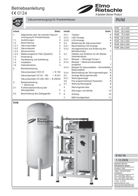
Vakuumversorgung für Krankenhäuser<br />
<strong>RVM</strong><br />
Inhalt:<br />
Seite:<br />
1. Allgemeines über die zentrale Vakuumversorgung<br />
für Krankenhäuser 2<br />
1.1 Ausführungen 2<br />
1.2 Beschreibung 2<br />
1.2.1 Vakuumpumpen 2<br />
1.2.2 Vakuumkessel 2<br />
1.2.3 Steuerschrank 2<br />
1.2.4 Bakteorologischer Filter (Zubehör) 2<br />
1.3 Anwendung 2<br />
1.4 Handhabung und Aufstellung 3<br />
1.5 Installation 3<br />
1.6 Inbetriebnahme 4<br />
2. <strong>Betriebsanleitung</strong><br />
Vakuumpumpen VCE 25 ➝ B 150<br />
Vakuumpumpen VC 50 - 150 ➝ B 231<br />
Vakuumpumpen VC 202 / 303 ➝ B 232/20<br />
3. <strong>Betriebsanleitung</strong><br />
➝ Steuerung 5<br />
3.1 Funktionsbeschreibung des<br />
Steuergerätes 5<br />
3.2 Beschreibung des Dialoggeräts 5<br />
<strong>RVM</strong><br />
Inhalt:<br />
Seite:<br />
3.2.1 Tastatur 6<br />
3.2.2 LED-Anzeige 6<br />
3.2.3 LCD-Anzeige 6<br />
3.3 Bedienung der Vakuumpumpen 6<br />
3.3.1 Beschreibung LCD-Anzeige 6<br />
3.3.2 Anzeigenwechsel und Änderung des<br />
Betriebsmodus 7<br />
3.4 Defekte und Verfahren für die Wiederinbetriebnahme<br />
7<br />
3.4.1 Beispiel ➝ Ölmangel Pumpe 1 7<br />
3.4.2 Beispiel ➝ Motorschutzschalter<br />
ausgelöst 7<br />
3.4.3 Beispiel für Vakuumdefekt – Zentraldefekt -<br />
Batteriedefekt 8<br />
3.4.4 Beschreibung der Störungsmeldungen 8<br />
3.5 Anzeige Wartungsintervalle 8<br />
3.5.1 Wartungsanzeige 8<br />
3.6 Frei programmierbare Parameter 8<br />
3.7 Wartung Steuergerät 8<br />
4. Wartungsintervalle 9<br />
5. Störungen und Abhilfe 10<br />
6. Anhang 10<br />
7. EMV-Vertäglichkeit 11<br />
<strong>RVM</strong> 25.3.000<br />
<strong>RVM</strong> 50.3.000<br />
<strong>RVM</strong> 75.3.000<br />
<strong>RVM</strong> 100.3.000<br />
<strong>RVM</strong> 150.3.000<br />
<strong>RVM</strong> 200.3.000<br />
<strong>RVM</strong> 300.3.000<br />
B 60/4b<br />
1.12.2009<br />
Gardner Denver<br />
Schopfheim GmbH<br />
Postfach 1260<br />
79642 SCHOPFHEIM<br />
GERMANY<br />
Fon +49 7622 / 392-0<br />
Fax +49 7622 / 392-300<br />
e-mail: er.de@<br />
gardnerdenver.com<br />
www.gd-elmorietschle.com
1. Allgemeines über die zentrale Vakuumversorgung für Krankenhäuser<br />
1.1 Ausführungen<br />
Diese <strong>Betriebsanleitung</strong> gilt für Krankenhauskompaktanlagen des Typs <strong>RVM</strong>.<br />
«ZENTRALE VAKUUM-VERSORGUNG FÜR KRANKENHÄUSER»<br />
Das Saugvermögen bei freier Ansaugung beträgt 3 x 25, 3 x 50, 3 x 70, 3 x 100, 3 x 150, 3 x 200 und 3 x 300 m 3 /h bei 50 Hz.<br />
Der Enddruck der Pumpen ist 10 mbar (abs.). Die Abhängigkeit des Saugvermögens vom Ansaugdruck zeigen die Datenblätter<br />
D154 (VCE), D 231 (VC 50 - 150) und D 232/20 (VC 202 + 303).<br />
1.2 Beschreibung<br />
Die Vakuumanlage für Krankenhäuser Typ <strong>RVM</strong> besteht aus drei Vakuumpumpen des Typs VCE oder VC, aufgebaut auf einem<br />
stehenden Rahmen, einem Vakuumkessel, einem Steuerschrank mit frei programmierbarer Steuerung sowie ein Kondensatabscheider<br />
auf der Druckseite. Als Zubehör ist ein saugseitiger Bakterienfilter mit By-pass erhältlich.<br />
Ein saugseitig eingebautes Rückschlagventil vor jeder Pumpe verhindert ein Belüften des evakuierten Systems nachdem<br />
Ausschalten der Pumpen. Das Rückschlagventil dient darüber hinaus als Sicherheitsfunktion und verhindert, dass sich der<br />
Förderraum der Pumpe nach dem Ausschalten mit Öl füllt, was bei einem Neustart zu Ölschlägen führen würde. Zu Wartungszwecken<br />
ist vor jeder Pumpe ein Kugelhahn eingebaut, um diese während der Betriebszeit vom System trennen zu können.<br />
Für eine konstante Druckregelung kann die Anlage optional mit einem Magnetventl für jede Pumpe ausgerüstet werden.<br />
1.2.1 Vakuumpumpen<br />
Die eingesetzten Vakuumpumpen arbeiten nach dem Drehschieberprinzip, sind ölumlaufgeschmiert mit integriertem<br />
Ölnebelabscheider und Rückführung des Öls in den Ölkreislauf. Saugseitig ist die Pumpe durch einen Siebfilter vor<br />
Verschmutzungen geschützt.<br />
1.2.2 Vakuumkessel<br />
Der Vakuumkessel ist in stehender (alternativ liegender) Ausführung mit einem Volumen von 300, 500, 800, 1000, 1500, 2000,<br />
3000 oder 5000 l lieferbar. Materialspezifikation Stahl St 37-2, außen lackiert, alternativ verzinkt.<br />
Alle Vakuumkessel sind mit einem Kugelhahn für den Kondensat-Ablass ausgerüstet und dürfen nur für Vakuum<br />
benutzt werden.<br />
1.2.3 Steuerschrank<br />
Die Anlage ist mit einer frei programmierbaren Steuerung ausgerüstet.<br />
Die Bedienung erfolgt über ein Bedientableau mit visualisierter Anzeige. Die Ausführung entspricht den neuesten europäischen<br />
Normen (siehe Bedienungsanleitung für Steuergerät).<br />
1.2.4 Bakteorologischer Filter (Zubehör)<br />
Der bakteriologischer Filter ist als Zubehör für alle Anlagengrößen erhältlich. Er wird saugseitig vor dem Kessel montiert und<br />
verhindert, dass Keime über das Vakuumsystem ins Freie gelangen.<br />
Es müssen Minimum zwei Filter im Bypass montiert werden. Im Austritt der Zentrale befindet sich ein Abscheiderbehälter, um<br />
den Austritt von Öldämpfen zu reduzieren.<br />
1.3 Anwendung<br />
Als zentrale Vakuumversorgung in Krankenhäuser z.B. für Sekretabsaugung.<br />
Der Arbeitsdruck liegt normalerweise bei 200 - 400 mbar (abs.) oder im konstanten Vakuum zwischen 10 - 500 mbar (abs.).<br />
Die abgesaugte Luft darf kein Wasser und keine anderen Flüssigkeiten enthalten. Aggressive oder brennbare Gase<br />
und Dämpfe dürfen nicht abgesaugt werden.<br />
Die Umgebungstemperatur und die Ansaugtemperatur muss zwischen 5 und 40°C liegen. Bei Temperaturen außerhalb<br />
dieses Bereiches bitten wir um Rücksprache.<br />
- 2 -
1.4 Handhabung und Aufstellung<br />
Im Normalbetrieb können Oberflächentemperaturen von über 70°C auftreten, die Berührung dieser Teile ist zu vermeiden.<br />
Die <strong>RVM</strong> Zentralanlagen können nur in horizontaler Einbaulage fehlerfrei betrieben werden.<br />
Das Öffnen des Schaltschranks darf nur außerhalb des Betriebs von einem qualifizierten Fachmann gemäß der<br />
Norm EN 60204 durchgeführt werden.<br />
Das Bedienpult und der Schaltschrank müssen zugänglich bleiben.<br />
Die bakteriologische Filtereinheit muss für die Wartung zugänglich sein.<br />
Bei Aufstellung höher als 1000 m über dem Meeresspiegel macht sich eine Leistungsminderung bemerkbar. In diesem<br />
Fall bitten wir um Rücksprache.<br />
Die zentrale Vakuumversorgung für Krankenhäuser wird üblicherweise in einem Technikraum aufgestellt. Die Umgebungstemperatur<br />
darf 40°C nicht überschreiten.<br />
Bei Aufstellung und Betrieb sind die aktuellen Unfallverhütungsvorschriften zu beachten.<br />
1. Der Vakuumanschluss befindet sich an der Stirnseite des Sammelrohrs.<br />
Bei zu enger und/ oder langer Saugleitung vermindert sich das Saugvermögen der Vakuumpumpe. Die Abluft muss<br />
gemäß den gültigen Normen ins Freie geführt werden.<br />
2. Vor dem Betrieb der Vakuumpumpe ist der Ölstand zu überprüfen (siehe oberes Öl-Schauglas (I), gegebenenfalls Öl nachfüllen).<br />
3. Die elektrische Zuleitung muss im Schaltschrank angeschlossen werden. Die Absicherung ist bauseits vorzusehen. Die elektrischen<br />
Daten sind mit den Daten des vorhandenen Stromnetzes zu vergleichen (Stromart, Spannung, Netzfrequenz, zulässige<br />
Stromstärke).<br />
Im Steuerschrank ist ein mechanischer Sicherheitsschalter (Vacuostat) installiert. Bei einem Steuerungsdefekt schaltet dieser<br />
automatisch bei einem Druck von 500 mbar (abs) eine oder zwei Vakuumpumpen ein. Ob eine oder zwei Pumpen aktiviert werden,<br />
ist abhängig von der Schalterposition 2S2 oder 2S3. Wenn 2S2 und 2S3 auf Pos. 1 gestellt ist, werden die Pumpen P1 und P3<br />
eingeschaltet, wenn 2S2 und 2S3 auf Pos. 2 gestellt ist, wird P2 eingeschaltet.<br />
Sollte unter diesen Umständen der Druck nicht aufrecht erhalten werden können, erfolgt eine Alarmierung.<br />
Die elektrische Installation darf nur von einer Elektrofachkraft unter Einhaltung der EN 60204 vorgenommen werden.<br />
Der Hauptschalter muss durch den Betreiber vorgesehen werden.<br />
1.5 Installation<br />
1. Allgemeine Informationen<br />
- Installation nach den augenblicklich geltenden Normen, darunter auch die Norm DIN EN ISO 7396-1:2007.<br />
- Der Einbau der Zentrale erfolgt in einem technischen Raum mit einem nivellierten Fussboden, mit einer ausreichenden<br />
Beleuchtung und einer Steckdose, einer geeigneten Tür, mit einer Ventilation durch einen Abzug (m³/h, siehe<br />
Tabelle) oder einer Klimaanlage. Vorzusehen ist eine Versorgung mit Drehstrom 400 V (Standard) mit einer bestimmten<br />
Leistung (kW, siehe Tabelle).<br />
- Brandschutz-Vorrichtung : die erforderlichen und geeigneten Feuerlöscher (Pulver) sind in der Nähe der Vakummzentrale<br />
anzuordnen.<br />
2. Technische Angaben<br />
Hinweise:<br />
- Die angegebenen Durchmesser Ø gelten für Verbindungsrohrleitungen zwischen der Vakuumzentrale und dem Benutzer.<br />
- Die Durchsätze des Ventilators sind für einen Temperaturunterschied von 10° C und für eine im Betrieb laufende<br />
Pumpe berechnet.<br />
- Filterung: bakteriologischer Filter (2 Filter, parallel im Bypass).<br />
Type kW Ø m³/h<br />
Filter Nr.<br />
<strong>RVM</strong> 25.3.000 2,22 25 mm 180 910092<br />
<strong>RVM</strong> 50.3.000 3,75 25 mm 260 910094<br />
<strong>RVM</strong> 75.3.000 5,55 25 mm 360 910094<br />
<strong>RVM</strong> 100.3.000 6,6 / 9,0 40 mm 530 910095<br />
<strong>RVM</strong> 150.3.000 9 / 12 50 mm 720 910096<br />
<strong>RVM</strong> 200.3.000 12 / 16,5 50 mm 960 910096<br />
<strong>RVM</strong> 300.3.000 16,5 / 22,5 50 mm 1300 910097<br />
- 3 -
3. Ausbau des Altgerätes<br />
- Der Ausbau des alten Geräts beim Einsatz einer neuen medizinischen Vakuumzentrale (Zentrale, Behälter, Rohrleitungen,<br />
Filterungen usw.) wird entweder durch den Kunden oder durch Elmo Rietschle vorgenommen, wobei<br />
Vorsichtsmassnahmen, die im Rahmen von durch Bakterien kontaminiertem Material sowie geltenden Bestimmungen<br />
zu berücksichtigen sind (dichte Handschuhe, Maske usw.).<br />
- Das Innere der Pumpe muss durch den Kunden dekontaminiert werden.<br />
- Im Rahmen des Ausbaus nach Ablauf der Lebensdauer einer Anlage sind die gleichen Vorsichtsmassnahmen vorzusehen.<br />
4. Ausfall der Spannung<br />
Bei Unterbrechung der Stromversorgung oder bei Ausfall der Spannung ist die Vakuumfunktion nicht mehr gewährleistet. Bei der<br />
Rückkehr der Stromversorgung wird die Zentrale automatisch wieder in Betrieb gesetzt und die Pumpen können jederzeit wieder<br />
anlaufen (hierzu sind die erforderlichen Sicherheitsmassnahmen zu treffen).<br />
5. Alarm (potentialfreie Kontakte geschlossen)<br />
- Die Alarmsignale müssen vom Klemmenkasten des Steuerschranks mit dem Sicherheitsraum des Krankenhauses verbunden<br />
werden.<br />
Alarm-Typ:<br />
* Vakuumdefekt: - 400 mbar<br />
* Alarm = Unterbrechung der Stromversorgung, Schutzschalter defekt und Ölniveau (option); Klemmenbelegung siehe Schaltplan<br />
1.6 Inbetriebnahme<br />
Vor dem Betrieb sind alle Überwachungs- und Sicherheitseinrichtungen auf Funktion zu prüfen.<br />
Vor Inbetriebnahme die Schrauben des Steuerpults überprüfen und gegebenenfalls nachziehen.<br />
Die Verlegung und Prüfung des Kabels obliegt dem Krankenhaus.<br />
1. Die Pumpen nacheinander einschalten und die Drehrichtung nach Pfeil (O) kontrollieren, indem Sie jede Vakuumpumpe im<br />
Handbetrieb kurz einschalten.<br />
2. Nach korrigierter Drehrichtung, kann der gewünschte Betriebsdruck am Bedienpult eingestellt werden.<br />
Vom Hersteller eingestellter Wert: - 800 mbar<br />
Konstantes Vakuum:<br />
± 20 mbar<br />
Übliches Vakuum:<br />
- 800 mbar; - 600 mbar<br />
Die Parameter dürfen ohne Abstimmung mit Elmo Rietschle nicht geändert werden.<br />
Nach evtl. Korrektur der Drehrichtung Motor erneut starten und nach ca. 2 Minuten wieder abstellen, um fehlendes Öl entsprechend<br />
Ölstand im Schauglas (I) nachzufüllen. Dieses Nachfüllen an der Einfüllstelle (H) muss wiederholt werden, bis sich der<br />
Ölkühler vollständig gefüllt hat. Die Einfüllstelle darf nicht bei laufender Pumpe geöffnet werden.<br />
Den Wahlschalter des Druckschalters auf Stellung 1 schalten, damit ist die Sicherheitsfunktion des Aggregates aktiviert.<br />
- 6 -
3. <strong>Betriebsanleitung</strong> ➝ Steuergerät<br />
Steuergerät für die Vakuumpumpen<br />
3.1 Funktionsbeschreibung des Steuergeräts<br />
Das Steuergerät der Vakuumpupen ist ein in sich geschlossenes Gerät, das einen speziell für eine möglichst benutzerfreundliche<br />
Anwendung entwickelten Steuerteil (SPS) umfasst, sowie einen Leistungsteil, der je nach Pumpe, für deren Bedienung<br />
er vorgesehen ist, in verschiedenen Versionen erhältlich ist. Es gibt auch mehrere Versionen des Steuergeräts, die für<br />
die Steuerung von Vakuumpumpen vorgesehen sind.<br />
3.2 Beschreibung des Dialoggeräts<br />
Das Dialoggeräts umfasst neben sieben Tasten für die Programmierung und den Dialog mit dem Steuergerät eine LCD<br />
Anzeige.<br />
LCD Anzeige mit<br />
Hintergrundbeleuchtung<br />
4 x 20 W<br />
- 5 -
Beschreibung der Elemente des Dialoggeräts<br />
3.2.1 Tastatur<br />
Die Tastatur umfasst nur sieben Tasten, und ist damit einfach und schnell zu bedienen.<br />
• Vier gelbe Pfeiltasten für die Auswahl von Daten, Parametern und Menüs, die folgendermassen bezeichnet werden:<br />
FG (Pfeil nach links)<br />
FD (Pfeil nach rechts)<br />
Die Tasten FG und FD dienen zur Menuauswahl.<br />
FH (Pfeil nach oben)<br />
FB (Pfeil nach unten)<br />
Die Tasten FH und FB dienen zur Auswahl des Betriebsmodus und zur Änderung von Parametern.<br />
Hinweis: Mit Hilfe dieser Pfeiltasten können auch die programmierten Daten ohne ungewollte Änderung abgefragt werden, da<br />
jede Änderung durch die Enter-Taste bestätigt werden muss, um von der SPS berücksichtigt zu werden.<br />
• Eine Entertaste beispielsweise zum Bestätigen des Parameters oder des Betriebsmodus:<br />
• Eine Wartungstaste, mit der beispielsweise die Betriebsdauer abgefragt werden kann:<br />
• Eine Alarmquittierungstaste, mit der beispielsweise die Übertragung einer Alarmmeldung verhindert werden kann:<br />
3.2.2 Anzeige LEDS<br />
• Eine grüne Leuchtdiode zeigt die Spannungsversorgung des Steuergeräts an.<br />
• Eine rote Leuchtdiode zeigt einen Alarm an, beispielsweise einen Schutzschalterdefekt.<br />
• Eine blaue Leuchtdiode zeigt an, dass die Wartung erforderlich ist.<br />
3.2.3 LCD-Anzeige<br />
Diese Anzeige ist für den Dialog zwischen dem Bediener und der SPS vorgesehen. Im Normalfall zeigt er die Funktionsweise,<br />
Vakuum in mbar und den Betriebsmodus der Pumpen an. Seine Funktionen werden im folgenden Teil beschrieben.<br />
3.3 Bedienung des Steuergeräts für Vakuumpunpen<br />
3.3.1 Beschreibung LCD-Anzeige<br />
Auf der LCD Anzeige werden mehrere Parameter angegeben.<br />
• Istwert als DIfferenzdruck in mbar.<br />
• Betriebsmodus.<br />
• Grundlastpumpe.<br />
Vakuum: -xxxmB<br />
p1 : M p2 : M p3 : M<br />
xxxmB : Vakuum in mbar am Vakuumsensor<br />
P : Entspricht dem Pumpentyp an jedem SPS-Ausgang. Ein Grosses P gibt die Grundlastpumpe, ein kleines p gibt das<br />
Folgeaggregat an.<br />
M : Betriebsmodus :<br />
· S für Stillstand.<br />
· H für Handbetrieb.<br />
· A für Automatik außer Betrieb.<br />
· F für Automatik in Betrieb.<br />
· D für Defekt.<br />
Die Alarmmeldungen werden auf Zeile 2 der LCD Anzeige gemeldet, zum Beispiel:<br />
· Bei Ölstandsproblem ➝ OELSTANDDEFEKT (nur wenn Ölniveauschalter vorhanden)<br />
· Bei Vakuumproblem ➝ VAKUUMDEFEKT<br />
· Bei Batterieprobleme ➝ BATTERIEDEFEKT<br />
- 6 -
3.3.2 Anzeigewechsel und Änderung des Betriedsmodus<br />
Dafür werden die Richtungstasten sowie die Entertaste<br />
verwendet.<br />
Mit den Tasten ← und → kann zwischen Betriebsanzeige,<br />
Statusanzeige und Pumpenzustandsanzeige hin und hergewechselt<br />
werden. Je nach angeschlossenen Pumpen<br />
gelangt man zu folgendem.<br />
Pumpe x<br />
« Pumpenzustand »<br />
x : Pumpennummer (1 bis 4)<br />
« Pumpenzustand » : AUTOMATIK<br />
: HANDBETRIEB<br />
: STILLSTAND<br />
• Die Auswahl dieser drei Betriebsmodi erfolgt mit den Tasten ↑ und ↓, wobei der Moduswechsel mit der Enter Taste zu<br />
bestätigen ist. Mit den Tasten ← und → gelangt man wieder zum Hauptmenü zurück.<br />
• Im Automatikmodus wird die Inbetriebnahme oder die Ausserbetriebnahme von der SPS gemäss der programmierten Parameter<br />
oder der Betriebsbedingungen gesteuert. Es erscheinen die folgenden Zustandsmeldungen:<br />
« Pumpenzustand » : AUTOMATIK IN BETRIEB<br />
: AUTOMATIK AUSSER BETRIEB<br />
3.4 Defekte und Verfahren für die Wiederinbetriebnahme<br />
Die Zeile 2 der LCD Anzeige informieret den Bediener über eventuelle Defekte.<br />
Es muss die Alarmquittierungstaste betätigt werden. In der LCD Anzeige erscheint der Defekt. Wenn nichts angezeigt wird, heißt<br />
das, dass eine Pumpe defekt ist. Für weitere Informationen müssen Sie in den Status der Pumpe gehen. Andere Defekte werden<br />
direkt angezeigt:<br />
3.4.1 Beispiel für einen Ölstandsmangel bei Pumpe 1 (nur wenn Ölniveauschalter vorhanden)<br />
LCD Anzeige Pumpe 1<br />
Vakuum: -xxxmb<br />
Defekt<br />
p1 : D P2 : F p3 : H<br />
Pumpe 1<br />
Stillstand<br />
Ölstandsdefekt<br />
Es muss die Alarmquittierungstaste betätigt werden, bevor die Wiederinbetriebnahme gewählt wird:<br />
• Mit der ACQ – Taste kann auch die Übertragung einer Alarmmeldung verhindert werden, d.h., dass das vom Übertragungsrelais<br />
gegebene Alarmsignal 15 Minuten lang blockiert wird.<br />
3.4.2 Beispiel für Motorschutzschalter ausgelöst bei Pumpe 1<br />
LCD Anzeige Pumpe 1<br />
Vakuum: -xxxmB<br />
Defekt<br />
p1 : D P2 : F p3 : H<br />
Pumpe 1<br />
Stillstand<br />
Schutzschalterdefekt<br />
Es muss die Alarmquittierungstaste betätigt werden, bevor die Wiederinbetriebnahme gewählt wird:<br />
• Mit der Alarmquittierungstaste kann auch die Übertragung einer Alarmmeldung verhindert werden, d.h., dass das vom<br />
Übertragungsrelais gegebene Alarmsignal 15 Minuten lang blockiert wird.<br />
- 7 -
3.4.3 Beispiel für Vakuumdefekt oder Batteriedefekt<br />
LCD Anzeige Pumpe 1<br />
Vakuum: -xxxmb<br />
DEFEKT<br />
p1 : F p2 : F p3 : H<br />
DEFEKT<br />
BATTERIEDEFEKT<br />
VAKUUMDEFEKT<br />
Es muss die Alarmquittierungstaste betätigt werden, bevor die Wiederinbetriebnahme gewählt wird:<br />
• Mit der Alarmquittierungstaste kann auch die Übertragung einer Alarmmeldung verhindert werden, d.h., dass das vom<br />
Übertragungsrelais gegebene Alarmsignal 15 Minuten lang blockiert wird.<br />
3.4.4 Beschreibung der Störmeldungen<br />
- Der Ausgang Vakuumdefekt ist aktiviert ( der Kontakt öffnet sich ), wenn das Vakuum unter – 400 mbar fällt. Der Kontakt<br />
schließt sich automatisch, wenn die Vakuumhöhe gleich oder höher - 400 mbar beträgt.(Dieser Wert wurde werkseitig eingestellt<br />
und kann nicht verändert werden).<br />
- Der Ausgang Defekt ist aktiviert (der Kontakt öffnet sich), sobald ein Ölstanddefekt, Schutzschalterdefekt oder Batteriedefekt<br />
auftritt. Dieser Ausgang wird deaktiviert (der Kontakt schließt sich), nach dem mit der Alarmquittierungstaste quittiert wurde.<br />
Falls der Defekt nach 15 Minuten immer noch vorhanden ist, wird der Ausgang erneut aktiviert.<br />
• Ein Ölstanddefekt wird erst nach 10 s im stabilen Zustand, gemeldet (option).<br />
• Ein Schutzschalter, Batteriedefekt wird sofort gemeldet.<br />
3.5 Anzeige Wartungsintervalle<br />
Durch Betätigen der Wartungstaste wird der Betriebsstundenzähler für die Pumpenwartung im LCD aktiviert. Durch Betätigen<br />
der → Taste kommt wieder die Standard LCD - Anzeige.<br />
Von einer Pumpenzustandsanzeige kann durch anhaltendes Drücken der Entertaste, in der vierten Zeile der LCD Anzeige die<br />
Anzahl der Betriebsstunden der jeweiligen Pumpe angezeigt werden.<br />
Wartungsintervalle Pumpe 1<br />
WARTUNG :<br />
XXXXXX H<br />
PUMPE 1<br />
AUTOMATIK IN BETRIEB<br />
3.5.1 Wartungsanzeige<br />
Sobald der Betriebsstunden Zähler die bei der Installation programmierte Wartungszeit erreicht hat, leuchtet die blaue Leuchtdiode<br />
auf.<br />
3.6 Frei programmierbare Parameter<br />
Für die Programmierung der Betriebsparameter sind gleichzeitig die Tasten FB, FH und Entertaste 10 Sekunden lang zu betätigen.<br />
Für die Eingabebestätigung von neuen Daten, muss die Enteraste gedruckt werden.<br />
Betriebsparameter : ( mit → wählen):<br />
- VAKUUMREGELUNG : xxxx mB<br />
- PUMPENROTATION : xxxx H<br />
- STUNDENREGELUNG : xxxx<br />
- MINUTENREGULUNG : xxxx<br />
- STUNDE VORMITTAG : xxxx (Stundenaufgabe für beginn Tagesbetrieb (wenn Tag und Nachtbetrieb unterschiedlich)<br />
im Tagesbetrieb läuft Pumpe durch. Wenn Standardbetrieb = 0 eingeben)<br />
- STUNDE NACHT : xxxx (Stundenangabe wann Nachbetrieb beginnt. Nachbetrieb = automatische Pumpeneinschaltung<br />
zwischen – 600 und – 800 mbar. Wenn Standardbetrieb = 24 eingeben)<br />
Entertaste drücken für Rückkehr zur LCD – Anzeige<br />
3.7 Wartung Steuergerät<br />
Das Steuergerät soll regelmäßig gereinigt werden.<br />
XXXXXX H<br />
- 8 -
4. Wartungsintervalle<br />
Wartung nach Betriebsstunden<br />
1000 2000 3000 4000 5000 6000 7000 8000 9000 1000<br />
Stunden P1<br />
Stunden P2<br />
Stunden P3<br />
Ölwechsel<br />
Reinigung Gasballastventil<br />
Filterwechsel: Patrone (bakteriologisch)<br />
Kontrolle: Ölleckage<br />
Kontrolle: Magnetventil (option)<br />
Kontrolle: Abluftfilter<br />
Kontrolle: Ansaugfilter<br />
Austausch: Entölerelement<br />
Austausch: Dichtung Entölereinsatz<br />
Reinigung der Zentralanlage<br />
<br />
<br />
<br />
<br />
<br />
<br />
<br />
<br />
<br />
<br />
Datum und Unterschrift<br />
Bemerkungen:<br />
Alle Wartungsarbeiten sollen mit dichten Handschuhen ausgeführt werden.<br />
Für die Wartung der Geräte, verwenden Sie nur Original Elmo Rietschle Ersatzteile und Öle, um einen störungsfreien Betrieb der<br />
Zentralanlage zu gewährleisten.<br />
Die Ansaugrohre und Abluftrohre jedes 5 Jahr ersetzen.<br />
Wir empfehlen eine vollständige Überholung der Zentralanlage nach Ablauf von 15.000 Betriebsstunden durch Elmo Rietschle.<br />
Alle Wartungsarbeiten (1000 Stunden) sollen wenigstens ein Mal pro Jahr und die zusätzlichen Wartungsarbeiten (2000 Stunden)<br />
wenigstens jedes 5 Jahr ausgeführt werden.<br />
Die Verschleißteile, Öle, Patronen sind Sonderabfall und nach den landesüblichen Abfallgesetzen durch das Krankenhaus zu entsorgen.<br />
Die Puffer Batterie der Steuerung muss nach Ablauf von zwei Jahren getauscht werden.<br />
Das Magnetventil (option) muss jährlich auf Funktion geprüft werden.<br />
Folgende vorgehensweise wird vorgeschlagen - prüfen im Handbetrieb:<br />
- Einschalten der jeweiligen Vakuumpumpe<br />
- Beobachten des Druckes<br />
- Bei keiner Änderung des Druckes das Magnetventi austauschen.<br />
- 9 -
5. Störungen und Abhilfe<br />
5. Störungen und Abhilfe<br />
5.1 Vakuumpumpe wird durch Motorschutzschalter<br />
abgeschaltet(siehe auch <strong>Betriebsanleitung</strong> Steuergerät):<br />
5.1.1 Netzspannung/Frequenz stimmt nicht mit den Motordaten<br />
überein.<br />
5.1.2 Anschluss am Motorklemmbrett ist nicht korrekt.<br />
5.1.3 Vakuumpumpe bzw. deren Öl ist zu kalt.<br />
5.1.4 Das Schmieröl hat eine zu hohe Viskosität.<br />
5.1.5 Die Luftentölelemente sind verschmutzt.<br />
5.1.6 Der Gegendruck bei Wegleitung der Vakuum-Abluft ist<br />
zu hoch.<br />
5.2 Durch zu niedrigen Ölstand wird die Pumpe aus geschaltet<br />
(Ölniveauschalter Option).<br />
5.2.1 Siehe Ölstand im Schauglas und nachfüllen<br />
5.3 Vakuumdefekt schaltet die Pumpe aus<br />
5.3.1 Prüfen ob Schlauch zum Vakuumaufnehmer richtig angeschlossen<br />
ist.<br />
5.3.2 Prüfen ob elektrische Spannung vorhanden ist.<br />
5.3.3 Vakuumlevel in Leitungen prüfen.<br />
5.5 Batteriedefekt<br />
5.5.1 Batterie auswechseln, Sie befindet sich unter der Abdeckung<br />
des Steuergerätes. Zum wechseln Hauptschalter<br />
auf 0, Batterie innerhalb von 5 Minuten wechseln,<br />
Hauptschalter wieder ein.<br />
5.6 Saugvermögen ist ungenügend:<br />
5.6.1 Bakteriologischer Filter ist verschmutzt.<br />
5.6.2 Programmierte Vakuumwerte prüfen, ebenfalls prüfen ob<br />
Leck im Vakuumsystem.<br />
5.7 Vakuumpumpe wird zu heiß:<br />
5.7.1 Umgebungs- oder Ansaugtemperatur ist zu hoch.<br />
5.7.2 Kühlluftstrom wird behindert.<br />
5.7.3 Fehler wie unter 5.1.4, 5.1.5 und 5.1.6.<br />
5.8 Vakuumpumpe erzeugt abnormales Geräusch:<br />
Anmerkung: Ein hämmerndes Geräusch der Lamellen<br />
beim Kaltstart ist normal, wenn es mit zunehmender<br />
Betriebstemperatur innerhalb von 2 Minuten verschwindet.<br />
5.8.1 Die Kupplungsgummis sind verschlissen (siehe „Wartung“<br />
Vakuumpumpen).<br />
5.8.2 Das Pumpengehäuse ist verschlissen (Rattermarken).<br />
Abhilfe: Reparatur durch Hersteller oder Vertragswerkstatt.<br />
5.8.3 Lamellen sind beschädigt.<br />
5.8.4 Fehler wie 5.1.3 und 5.1.4.<br />
5.9 Wasser im Schmieröl:<br />
5.9.1 Pumpe saugt Wasser an.<br />
Abhilfe: prüfen ob im Filter und Behälter Wasser vorhanden<br />
ist.<br />
5.9.2 Pumpe saugt mehr Wasserdampf an, als ihrer<br />
Wasserdampfverträglichkeit entspricht.<br />
Abhilfe: Rücksprache mit dem Hersteller wegen verstärktem<br />
Gasballast.<br />
5.9.3 Pumpe arbeitet nur kurzzeitig und erreicht daher ihre normale<br />
Betriebstemperatur nicht.<br />
Abhilfe: Pumpe jeweils nach der Absaugung von Wasserdampf<br />
so lange mit geschlossener Saugseite weiter<br />
laufen lassen, bis das Wasser aus dem Öl ausgedampft<br />
ist.<br />
5.10 Steuerschrank<br />
5.10.1 Externer Spannungsabfall<br />
Der externe Spannungsausfall wird gemeldet und die<br />
Anlage automatisch mit dem Notstrom versorgt.<br />
5.10.2 Interner Spannungsabfall<br />
Im Falle eines Spannungsausfalles im Schaltschrank gibt<br />
es einen Alarm im Steuergerät. Dieser Alarm wird an das<br />
Krankenhaus weitergeleitet.<br />
Abhilfe: Hauptschalter auf Stellung 1 sowie Spannung<br />
zum Steuerschrank überprüfen.<br />
5.10.3 Ausfall SPS<br />
Bei Ausfall der SPS überbrückt der mechanische Druckschalter<br />
die SPS. Die Vakuumpumpen werden weiter<br />
betrieben, im Steuergerät erfolgt ein Alarm und ein rotes<br />
Signallicht blinkt.<br />
Abhilfe: Hauptschalter auf Stellung 0, 10 Sekunden warten,<br />
Hauptschalter auf Stellung 1. Sollte das Problem<br />
weiterbestehen, verständigen Sie bitte den Service von<br />
Elmo Rietschle.<br />
6. Anhang<br />
Reparaturarbeiten: Bei Reparaturarbeiten vor Ort muss der Motor<br />
von einer Elektrofachkraft vom Netz getrennt werden, so dass<br />
kein unbeabsichtigter Start erfolgen kann. Für Reparaturen muss<br />
der Hersteller oder Partner von Elmo Rietschle in Anspruch genommen<br />
werden, insbesondere, wenn es sich evtl. um<br />
Garantiereparaturen handelt. Die Anschrift der für Sie zuständigen<br />
Partner von Rietschle kann beim Hersteller erfragt werden<br />
(siehe Hersteller-Adresse). Nach einer Reparatur bzw. vor<br />
der Wiederinbetriebnahme sind die unter „Installation“ und „Inbetriebnahme“<br />
aufgeführten Maßnahmen wie bei der Erstinbetriebnahme<br />
durchzuführen.<br />
Innerbetrieblicher Transport: Zum Anheben und Transportieren<br />
der Anlage benützen Sie bitte einen Stapler oder Hubwagen.<br />
Achtung! Zum Anheben der Anlage dürfen auf keinen Fall<br />
die Transportösen der Vakuumpumpe verwendet werden.<br />
Lagerhaltung: Die Vakuumpumpe ist in trockener Umgebung<br />
mit normaler Luftfeuchtigkeit zu lagern. Bei Langzeit-Lagerung<br />
(länger als 3 Monate) empfehlen wir die Verwendung eines<br />
Konservierungsöles anstelle des Betriebsöles.<br />
Wichtig: Für die Wartung der Geräte, verwenden Sie nur Original<br />
Elmo Rietschle Ersatzteile und Öle, um einen störungsfreien<br />
Betrieb der Zentralanlage zu gewährleisten.<br />
Entsorgung: Die Verschleißteile (als solche in der Ersatzteillistegekennzeichnet)<br />
sind Sonderabfall und nach den landesüblichen<br />
Abfallgesetzen zu entsorgen.<br />
Änderungen: Wir informieren Sie, dass jede Änderung dieses<br />
Materials durch die Direktive 93/42/CEE nicht erlaubt ist. Man muss<br />
Elmo Rietschle bei jeder Änderung unbedingt zu Rate ziehen.<br />
Installation: Die Installation der Vakuum Anlage sowie der verwendeten<br />
Zubehörteile muss der Norm 93/42/CEE entsprechen.<br />
<strong>RVM</strong> 25.3.000 50.3.000 75.3.000 100.3.000 150.3.000 200.3.000 300.3.000<br />
Schalldruckpegel (max.), für<br />
1 Pumpe im Betrieb<br />
Gewicht (max.)<br />
Länge (max.)<br />
Breite<br />
Höhe<br />
dB(A)<br />
50 Hz<br />
65 67 68 70 72 76 76<br />
kg 160 190 220 315 320 482 665<br />
mm 830 830 830 1100 1100 1100 1100<br />
mm 650 650 650 850 850 850 850<br />
mm 1300 1300 1300 2100 2100 2200 2200<br />
- 10 -
7. EMV- Verträglichkeit<br />
7.1 Erklärung über EMV- Hinweise<br />
Bei der <strong>RVM</strong> handelt es sich um ein medizinisch- elektrisches Gerät.<br />
Solche Geräte unterliegen besonderen Vorsichtsmaßnahmen hinsichtlich der EMV.<br />
Bei der Installation und Inbetriebnahme sind die Hinweise der Betriebsanweisung zu beachten.<br />
Grundsätzlich können tragbare und montierte HF-Kommunikationseinrichtungen medizinisch-elektrische Geräte beeinflussen.<br />
Bitte die empfohlenen Schutzabstände beachten.<br />
7.2 Auflistung aller Leitungen und deren Längen<br />
Klemmenkasten X11 Motor<br />
Motor Vakuum Pumpe 1------------------ <br />
Motor Vakuum Pumpe 1------------------ <br />
Motor Vakuum Pumpe 1------------------ <br />
Motor Vakuum Pumpe 2------------------ <br />
Motor Vakuum Pumpe 2------------------ <br />
Motor Vakuum Pumpe 2------------------ <br />
Motor Vakuum Pumpe 3------------------ <br />
Motor Vakuum Pumpe 3------------------ <br />
Motor Vakuum Pumpe 3------------------ <br />
} 2,8 m<br />
} 2,1 m<br />
} 1,4 m<br />
Klemmenkasten X12 Instrumente<br />
Vakuum Magnetventil 1-------------------- <br />
Vakuum Magnetventil 1-------------------- <br />
Vakuum Magnetventil 2-------------------- <br />
Vakuum Magnetventil 2-------------------- <br />
Vakuum Magnetventil 3-------------------- <br />
Vakuum Magnetventil 3-------------------- <br />
Ölstand Vakuumpumpe 1------------------ <br />
Ölstand Vakuumpumpe 1------------------ <br />
Ölstand Vakuumpumpe 2------------------ <br />
Ölstand Vakuumpumpe 2------------------ <br />
Ölstand Vakuumpumpe 3------------------ <br />
Ölstand Vakuumpumpe 3------------------ <br />
} 3,0 m<br />
} 2,3 m<br />
} 1,6 m<br />
} 2,5 m<br />
} 1,8 m<br />
} 1,1 m<br />
7.3 Warnhinweise über Verwendung von Zubehör<br />
Die Verwendung von anderem Zubehör und Leitungen ist strikt untersagt.<br />
Der Grund hierfür ist:<br />
Die Veränderung des Gerätes kann zur erhöhten Aussendung oder zu einer reduzierenden Störfestigkeit führen.<br />
Ersatzteile dürfen nur von Elmo Rietschle erworben werden.<br />
- 11 -
7.4 Herstellererklärung<br />
Herstellererklärung - Elektromagnetische Aussendungen<br />
Die <strong>RVM</strong> ist für den Betrieb in einer wie unten angegebenen elektromagnetischen Umgebung bestimmt. Der Kunde oder der<br />
Anwender der <strong>RVM</strong> sollte sicherstellen, dass es in einer derartigen Umgebung betrieben wird.<br />
Störaussendungsmessungen Übereinstimmung Elektromagnetische Umgebung<br />
HF-Aussendungen nach CISPR 11 Gruppe 1 Die <strong>RVM</strong> verwendet HF-Energie<br />
ausschließlich zu seiner inneren<br />
Funktion. Daher ist seine HF-<br />
Aussendung sehr gering, und es ist<br />
unwahrscheinlich, dass benachbarte<br />
elektronische Geräte gestört werden.<br />
HF-Aussendungen nach CISPR 11 Klasse B Die <strong>RVM</strong> ist für den Gebrauch in allen<br />
Einrichtungen einschließlich denen im<br />
Aussendungen von Obersschwingungen nach<br />
IEC 61000-3-2<br />
Aussendungen von<br />
Spannungsschwankungen/Flickernach IEC<br />
61000-3-3<br />
Wohnbereich und solchen geeignet, die<br />
unmittelbar an das öffentliche<br />
Versorgungsnetz angeschlossen sind,<br />
das auch Gebäude versorgt, die zu<br />
Wohnzwecken genutzt werden.<br />
- 12 -
Herstellererklärung - Elektromagnetische Störfestigkeit<br />
Die <strong>RVM</strong> ist für den Betrieb in der unten angegebenen elektromagnetischen Umgebung bestimmt. Der Kunde oder der<br />
Anwender der <strong>RVM</strong> sollte sicherstellen, dass es in einer solchen Umgebung benutzt wird.<br />
Störfestigkeits-Prüfungen IEC 60601-Prüfpegel Übereinstimmungs-Pegel<br />
Entladung statischer<br />
Elektrizität (ESD) nach IEC<br />
61000-4-2<br />
Schnelle transiente<br />
elektrische<br />
Störgrößen/Burstsnach IEC<br />
61000-4-4<br />
Stoßspannungen (Surges)<br />
nach IEC 61000-4-5<br />
Spannungseinbrüche,<br />
Kurzzeitunterbrechungen und<br />
Schwankungen der<br />
Versorgungsspannungnach<br />
IEC 61000-4-11<br />
Magnetfeld bei der<br />
Versorgungsfrequenz (50/60<br />
Hz) nach IEC 61000-4-8<br />
± 6 kV Kontaktentladung<br />
± 8 kV Luftentladung<br />
± 2 kV für Netzleitungen<br />
± 1 kV für Eingangs- und<br />
Ausgangsleitungen<br />
± 1 kV Spannung<br />
Außenleiter-Außenleiter<br />
± 2 kV Spannung<br />
Außenleite-Erde<br />
< 5 % U T (> 95 % Einbruch<br />
der U T für ½ Periode)<br />
40 % U T (60 % Einbruch der<br />
U T) für 5 Perioden<br />
70 % U T (30 % Einbruch der<br />
U T ) für 25 Perioden<br />
< 5 % U T (> 95 % Einbruch<br />
der U T ) für 5 s<br />
2 kV / 4 kV / 6 kV<br />
2 kV / 4 kV / 8 kV<br />
Elektromagnetische<br />
Umgebung-Leitlinien<br />
Fußboden sollten aus Holz<br />
oder Beton bestehen oder<br />
mit Keramikfliesen versehen<br />
sein. Wenn der Fußboden<br />
mit synthetischem Material<br />
versehen ist, muss die<br />
relative Luftfeuchte<br />
mindestens 30 % betragen.<br />
2 kV Die Qualität der<br />
Versorgungsspannung sollte<br />
der einer typischen<br />
Geschäfts- oder<br />
Krankenhausumgebung<br />
entsprechen.<br />
0,5 kV / 1 kV<br />
0,5 kV/ 1,0 kV / 2,0 kV<br />
60 % / 100 MS<br />
30 % / 500 MS<br />
Die Qualität der<br />
Versorgungsspannung sollte<br />
der einer typischen<br />
Geschäfts- oder<br />
Krankenhausumgebung<br />
entsprechen.<br />
Die Qualität der<br />
Versorgungsspannung sollte<br />
der einer typischen<br />
Geschäfts- oder<br />
Krankenhausumgebung<br />
entsprechen. Wenn der<br />
Anwender der <strong>RVM</strong><br />
fortgesetzte Funktion auch<br />
beim Auftreten von<br />
Unterbrechungen der<br />
Energieversorgung fordert,<br />
wird empfohlen, die <strong>RVM</strong><br />
aus einer<br />
unterbrechungsfreien<br />
Stromversorgung oder einer<br />
Batterie zu speisen.<br />
3 A/m 3 A/m Magnetfelder bei der<br />
Netzfrequenz sollten den<br />
typischen Werten, wie sie in<br />
der Geschäfts- und<br />
Krankenhausumgebung<br />
vorzufinden sind,<br />
entsprechen.<br />
- 13 -
Herstellererklärung – Elektromagnetische Störfestigkeit – für Geräte oder Systeme, die nicht lebenserhaltend sind<br />
Die <strong>RVM</strong> ist für den Betrieb in der unten angegebenen elektromagnetischen Umgebung bestimmt. Der Kunde oder der<br />
Anwender der <strong>RVM</strong> sollte sicherstellen, dass es einer solchen Umgebung benutzt wird.<br />
Störfestigkeits-Prüfungen IEC 60601-Prüfpegel Übereinstimmungs-Pegel<br />
Geleitete HF-Störgrößen nach IEC 61000-4-6<br />
Gestrahlte HF-Störgrößen nach IEC 61000-4-3<br />
3 V Effektivwert<br />
150 kHZ bis 80 MHz<br />
3 V/M<br />
80 MHz bis 2,5 GHz<br />
3 V<br />
0,15 –80 MHz<br />
3 V/m<br />
80 –2500 MHz<br />
Empfohlene Schutzabstände zwischen tragbaren und mobilen HF-Telekommunikationsgeräten und dem Gerät<br />
oder System- für Geräte oder Systeme, die nicht lebenserhaltend sind<br />
Empfohlene Schutzabstände zwischen tragbaren und mobilem HF-Telekommunikationsgeräten und der <strong>RVM</strong><br />
Die <strong>RVM</strong> ist für den Betrieb in einer elektromagnetischen Umgebung bestimmt, in derdie HF-Störgrößen kontrolliert sind. Der<br />
Kunde oder der Anwender der <strong>RVM</strong> kann dadurch helfen, elektromagnetische Störungen zu vermeiden, indem er den<br />
Mindestabstand zwischen tragbaren und mobilen HF-Telekommunikationsgeräten (Sendern) und der <strong>RVM</strong> – abhängig von<br />
der Ausgangsleistung des Kommunikationsgerätes, wie unten angegeben- einhält.<br />
Nennleistung des Senders<br />
in W<br />
Schutzabstand abhängig von der Sendefrequenz<br />
150 kHz bis 80 MHz 80 MHz bis 800 MHz 800 MHz bis 2,5 GHz<br />
1 0,18 0,18 0,35<br />
- 14 -<br />
12.09 / PM7
Operating Instructions<br />
0124<br />
Medical Vacuum<br />
<strong>RVM</strong><br />
Contents:<br />
Page:<br />
1. General points on the Medical<br />
Vacuum Station 2<br />
1.1 Series 2<br />
1.2 Description 2<br />
1.2.1 Vacuum pumps 2<br />
1.2.2 Tanks 2<br />
1.2.3 Control panel 2<br />
1.2.4 Bacteriological filtration (optional<br />
accessories) 2<br />
1.3 Application 2<br />
1.4 Handling and setting up 3<br />
1.5 Installation<br />
1.5 Setting 4<br />
2. Operating Instructions<br />
Vacuum pumps VCE 25 ➝ BE 150<br />
Vacuum pumps VC 50 - 150 ➝ BE 231<br />
Vacuum pumps VC 202 / 303➝ BE 232/20<br />
3. Operating Instructions<br />
➝ Control panel 5<br />
3.1 Functional description of<br />
the box 5<br />
3.2 Description of the dialog unit 5<br />
<strong>RVM</strong><br />
Contents:<br />
Page:<br />
3.2.1 Keyboard 6<br />
3.2.2 Signalling LEDs 6<br />
3.2.3 LCD display: four lines of twenty<br />
characters 6<br />
3.3 How to use the vacuum pump<br />
control box 6<br />
3.3.1 Initial screen 6<br />
3.3.2 How to change the screen<br />
and modify the operating modes 7<br />
3.4 Failures and proceedings to restart 7<br />
3.4.1 Example of oil failure on pump 1 7<br />
3.4.2 Example of heat failure on pump 1 7<br />
3.4.3 Example of vacuum failure –<br />
function failure – battery failure 8<br />
3.4.4 Various signals and failures 8<br />
3.5 Maintenance 8<br />
3.5.1 Maintenance functionalities 8<br />
3.6 Parameters programmable by the user 8<br />
3.7 Maintenance control panel 8<br />
4. Maintenance intervalls 9<br />
5. Trouble Shooting 10<br />
6. Appendix 10<br />
7. EMC-Electromagnetic compatibility 11<br />
<strong>RVM</strong> 25.3.000<br />
<strong>RVM</strong> 50.3.000<br />
<strong>RVM</strong> 75.3.000<br />
<strong>RVM</strong> 100.3.000<br />
<strong>RVM</strong> 150.3.000<br />
<strong>RVM</strong> 200.3.000<br />
<strong>RVM</strong> 300.3.000<br />
BE 60/4b<br />
1.12.2009<br />
Gardner Denver<br />
Schopfheim GmbH<br />
Postfach 1260<br />
79642 SCHOPFHEIM<br />
GERMANY<br />
Fon +49 7622 / 392-0<br />
Fax +49 7622 / 392-300<br />
e-mail: er.de@<br />
gardnerdenver.com<br />
www.gd-elmorietschle.com
1. General points on the Medical Vacuum Station<br />
1.1 Series<br />
These instructions for use apply to medical vacuum stations (<strong>RVM</strong>) “MEDICAL VACUUM”. The nominal capacity of the stations at<br />
atmospheric pressure is 3 x 25, 3 x 50, 3 x 70, 3 x 100, 3 x 150, 3 x 200 and 3 x 300 m³/h at 50 Hz. The max. vacuum is 10 mbar<br />
(abs.). The pumping curves showing capacity against. Vacuum can be seen in data sheets D 154 (VCE), D 231 (VC 50 - 150) and<br />
D 232/20 (VC 202 + 303).<br />
1.2 Description<br />
The <strong>RVM</strong> vacuum stations consist of three vacuum pumps (VCE or VC type built on a standing framework), a skid for the pumps,<br />
a programmable control panel and a condensate separator on the pressure side. They can also include a bacteriological filter with<br />
by-pass.<br />
Each pump is equipped with a non-return valve so that once the pump is stopped air cannot enter the evacuated system or oil<br />
accumulate in the pressure chamber that would give rise to jerky starting. A manual valve is mounted on every device in order to<br />
isolate the pump for maintenance. The inlet of each pump can also be fitted with a solid valve for constant vacuum regulation.<br />
1.2.1 Vacuum pumps<br />
The vacuum pumps are of the oil lubricated rotary vane type and have built-in oil mist separator. Each pump is equipped with<br />
an inlet screen filter of stainless steel material.<br />
1.2.2 Tank<br />
Capacity: 300, 500, 800, 1000, 1500, 2000, 3000 or 5000 litres vertical (or horizontal version) with external paint finish.<br />
Material steel ST37-2 a galvanised version or vertical tanks can be manufactured upon request.<br />
Every tank is equipped with a valve of purge and must be used only for vacuum.<br />
1.2.3 Control Panel<br />
It controls the whole vacuum station through a programmable controller. Every panel features a display keyboard with a switch<br />
case comprising the electromechanical operating material. The control panel corresponds to the latest European standards<br />
(see operating manual control panel).<br />
1.2.4 Bacteriological filtration (optional accessories)<br />
Every station can be delivered with double bacteriological filter to prevent bacteria passing through the equipment. It is fitted<br />
with a drain valve and two filters with bacteriological cartridge. A outlet filter is fitted on the exhaust air pipe.<br />
Two filters must be minimum installed in the bypass. In the exit of the central a separator tank is located in order to reduce the<br />
exhaust of oil vapour.<br />
1.3 Application<br />
Vacuum stations are suction systems intended for medical use.<br />
They are designed to work in a pressure range of 200 mbar (abs.) to 400 mbar (abs.). Limitations of the operating pressure range<br />
are specified in the vacuum pump manual.<br />
The air must be free of water and other liquids. Aggressive or flammable gases and vapours cannot be drawn.<br />
The ambient and inlet temperatures must range from 5 to 40°C. For other temperatures please contact us.<br />
- 2 -
1.4 Handling and setting up<br />
A normally operated station can present pump surface temperatures for the elements (Q) above 70°C. Any contact<br />
with these parts must be avoided.<br />
<strong>RVM</strong> stations can only be correctly used in a horizontal position.<br />
The control panel must only be opened and checked when switched off and by a skilled worker, in accordance with<br />
the EN 60204 standard.<br />
The panel and electromechanical sub-system must remain free for display, programming and repairing.<br />
The bacteriological filtration and the collection pot must remain accessible for maintenance purposes.<br />
Should the station be installed higher than 1000 m over the sea level, a decrease in performance will take place. In this<br />
case, please contact us.<br />
The vacuum station must be installed in a ventilated plant room where the temperature should not exceed 40°C.<br />
Appropriate ventilation has to be provided. The room must be easily accessible.<br />
For operating and installation follow any relevant national standards that are in operation.<br />
1. Vacuum connection is found at the collector.<br />
The station performance will be affected if the inlet pipework is undersized and/or too lang. Discharge has to be<br />
directed outside in accordance with the current standards.<br />
2. You have to check whether oil condensate is present in the vacuum pumps (upper warning light (I) and add if necessary).<br />
3. Connect the control panel to the main supply via a circuit breaker. Check that the supply is compatible (current, voltage,<br />
frequency).<br />
An mechanical safe vacuum switch is installed in the control panel. It will started the pumps at –0,5 bar if it is a broke on the PLC<br />
(like the switch position 2S2 and 2S3: 2S2 and 2S3 on 1 = P1 + P3, 2S2 and 2S3 on 2 = P2).<br />
If the pressure under these circumstances cannot hold up an alarm takes place.<br />
The electrical connections and installation can only be performed by a skilled worker according to the EN 60204<br />
standard. The main switch (circuit breaker) of the room has to be provided by the user.<br />
1.5 Installation<br />
1. General information<br />
- Installation with norm DIN EN ISO 7396-1:2007.<br />
- The centrale does to be place in a technical local with a floor in level, sufficient light, power socket, an adequate door,<br />
ventilate with a fan (m³/h, see table) or with air condition. Use current force 3 x 400 V (standard) with an electrical<br />
power (kW, see table).<br />
- Disposition to fight against the fire : the extinguisher (powder) does to be place in proximity of the vacuum central.<br />
2. Technical datas<br />
Notes:<br />
- The shown diameter Ø are for connection pipes between the vacuum central and the operator.<br />
- The capacity of the fan are for an temperature difference of 10° C and for an running pump in operation calculated.<br />
- Filtring: bacterial filter (2 filter, parallel in the bypass).<br />
Type kW Ø m³/h<br />
Filter Nr.<br />
<strong>RVM</strong> 25.3.000 2,22 25 mm 180 910092<br />
<strong>RVM</strong> 50.3.000 3,75 25 mm 260 910094<br />
<strong>RVM</strong> 75.3.000 5,55 25 mm 360 910094<br />
<strong>RVM</strong> 100.3.000 6,6 / 9,0 40 mm 530 910095<br />
<strong>RVM</strong> 150.3.000 9 / 12 50 mm 720 910096<br />
<strong>RVM</strong> 200.3.000 12 / 16,5 50 mm 960 910096<br />
<strong>RVM</strong> 300.3.000 16,5 / 22,5 50 mm 1300 910097<br />
- 3 -
3. Dismounting of the old appliance<br />
- The dismounting of the old appliance at the use of a new medical vacuum central (central, tanks, pipes, filtrations etc),<br />
is either carried out through the customer or through the company Elmo Rietschle in which safety measure, that are<br />
to be taken in material contaminated through bacterias must be considered as well as current regulations (gloves,<br />
mask etc.).<br />
- The inside of the pump must be decontaminated by the customer.<br />
- The dismounting after downspoutof the lifespan of an installation the same safety measure are to use.<br />
4. Breakdown of the voltage<br />
In a case of current break or deficiency sector the function vacuum is not in function. In the back of the current the central function<br />
automatically and the pumps can be function in all moments. (take the security dispositions).<br />
5. Alarm (potential-free contacts closed)<br />
- That alarm signals must be connected by the terminal box of the control box with the security-area of the hospital.<br />
Alarm-Typ:<br />
* Vacuum-defect: - 400 mbar<br />
* Alarm = interruption of the power supply, protect switch defect and oil level (option); terminal connexions see wiring scheme<br />
1.6 Setting<br />
The vacuum and function alarms must always be connected and all the safety standards met in order to prevent<br />
exposing the persons to danger.<br />
The panel screws must be checked and screwed up if necessary before setting.<br />
The laying and check of the cable is incumbent on the hospital.<br />
1. The pumps must be run individually and the direction of rotation checked according to the arrow (O): start the devices separately<br />
in manual mode (see operating instructions of control panel).<br />
2. Once the direction of rotation is correct, set the desired vacuum rate on the control panel.<br />
Factory threshold:<br />
Constant vacuum:<br />
Current vacuum range:<br />
- 800 mbar<br />
± 20 mbar<br />
- 800 mbar; - 600 mbar<br />
The parameters may not be modified without agreement of Elmo Rietschle.<br />
Start the station with each pump in automatic position (see operating instructions of panel). Once every pump has been operating<br />
for about two minutes, stop the devices again to add oil if the warning light (I) indicates need. The filling opening must remain<br />
closed while running.<br />
Oil must be added for the pumps through the filler opening (H) until the cooling radiator is full. The filler opening must not be<br />
opened while the pump is running.<br />
The selector switch of the pressure switch connect on position 1, so that the safety-function of the aggregate is activated.<br />
- 4 -
3. Operating Instructions ➝ Control unit<br />
Control unit for vacuum pumps<br />
3.1 Description of control unit functions<br />
The vacuum pump control unit is a self-contained product consisting of a controller specifically designed for easy use and a<br />
power section. Several versions of this unit are available, depending on the type of pump in use.<br />
3.2 Description of the interactive terminal<br />
The interactive terminal comprises a backlight display consisting of four 20 character lines in addition to seven keys for<br />
programming and communicating with the unit.<br />
Backlight display<br />
consisting of four<br />
20 character lines<br />
- 5 -
Description of the dialog unit<br />
3.2.1 Keyboard<br />
The keyboard consist of no more than 7 keys for quick and easy use.<br />
• Four yellow arrow keys for selecting data, parameters and menus:<br />
FG (left arrow)<br />
FD (right arrow)<br />
The PFL and PFR keys are used to select menus (basic screen and pump status screens).<br />
FH (upward arrow)<br />
FB (downward arrow)<br />
The PFO and PFU keys are used to select operating modes an modify parameters.<br />
Note: These arrow keys are also used to view programmed data without making unwanted changes, as all modifications<br />
must be enabled by pressing the VAL key in order to be registred by the controller.<br />
• An Enter key, e.g. for parameters or operating modes:<br />
• A Maintenance key, e.g. for viewing the number of operating hours:<br />
• A Warning key, e.g. for inhibiting the warning trigger:<br />
3.2.2 Led indicators<br />
• A green led indicates that the unit is switched on.<br />
• A red led signifies a warning, e.g. a heat deficiency.<br />
• A blue led indicates that maintenance is required.<br />
3.2.3 Liquid crystal display consisting of four 20-character lines<br />
This display enables the user and the controller to communicate with each other. In normal circumstances it indicates the<br />
operating context, vacuum in mbar and pump operating mode. Its functions will be examined in detail in the next section.<br />
3.3 Using the vacuum pump control unit<br />
3.3.1 Initial screen<br />
The initial screen displays a number of parameters, starting with the vacuum reading followed by the operating mode and pump<br />
sequence.<br />
Vacuum: -xxxmB<br />
p1 : M p2 : M p3 : M<br />
xxxmB : Vacuum in mbar on the vacuum detector<br />
P<br />
: Signifies the type of motor, P for pump on each controller outlet. An upper-case P indicates the master pump, i.e. the<br />
first pump to start (the same applies for the upper-case C).<br />
M : Operating mode:<br />
· S for stop.<br />
· H for induced operation.<br />
· A for automatic off.<br />
· F for automatic on.<br />
· D for deficiency.<br />
In some cases, the two bottom lines of the display may give warning messages:<br />
· If there is an oil level deficiency or heat deficiency -> DEFICIENCY<br />
· If there is an vacuum deficiency -> VACUUM DEFICIENCY<br />
· If there is an battery deficiency -> BATTERY DEFICIENCY<br />
- 6 -
3.3.2 Changing screens and modifying operating modes<br />
The arrow keys and Enter key are used for this purpose.<br />
The ← and → keys are used to scroll between the initial<br />
screen and pump status screens. The following screens<br />
appear in accordance whith the pumps connected.<br />
Pump x<br />
„Pump status“<br />
x : Pump number (1 to 4)<br />
„Pump status“ : AUTOMATIC<br />
: INDUCED OPERATION<br />
: STOP<br />
• These three modes are selected by pressing the ↑ and ↓ keys. A change of mode must be enabled by pressing the key. The<br />
← and → keys are used to return to the initial screen.<br />
• In AUTOMATIC mode, the on and off functions are governed by the controller, depending on the programmed parameters and<br />
on the context. The following status messages are displayed:<br />
„Pump status“ : AUTOMATIC ON<br />
: AUTOMATIC OFF<br />
3.4 Deficiencies and re-start procedures<br />
One line of the display inform the user of the deficiencies.<br />
In this case press on the warning key (ACQ). The display will show you the deficiency. If nothing is write on the display, it will<br />
inform you that one pump is deficiency. For further information, you must go in the status of the pump. Other defects are shown<br />
directly:<br />
3.4.1 Example of an oil level deficiency for pump 1 :<br />
Initial screen<br />
Pump 1 status screen<br />
Vacuum: -xxxmb<br />
Deficiency<br />
p1 : D P2 : F p3 : H<br />
Pump 1<br />
Stop<br />
Oil level deficiency<br />
When the oil level deficiency has been rectified, the ACQ key must be pressed before proceeding to re-star.<br />
Note : The ACQ. Key is also used to inhibit the triggering of an alarm, i.e. the warning given by the trigger relay is inhibited for<br />
15 minutes.<br />
3.4.2 Example of a heat deficiency on pump 1 :<br />
Initial screen<br />
Vacuum: -xxxmB<br />
Deficiency<br />
p1 : D P2 : F p3 : H<br />
Pump 1 status screen<br />
Pump 1<br />
Stop<br />
Heat deficiency<br />
When the HEAT deficiency has been rectified, the ACQ key must be pressed before proceeding to re-star.<br />
Note : The ACQ. Key is also used to inhibit the triggering of an alarm, i.e. the warning given by the trigger relay is inhibited for<br />
15 minutes.<br />
- 7 -
3.4.3 Example of a vacuum or battery deficiency<br />
Initial screen Pump 1 status screen<br />
Vacuum: -xxxmb<br />
DEFICIENCY<br />
p1 : F p2 : F p3 : H<br />
DEFICIENCIES :<br />
BATTERY DEFICIENCY<br />
VACUUM DEFICIENCY<br />
When the deficiency has been rectified, the ACQ key must be pressed before proceeding to re-star:<br />
Note: The ACQ. Key is also used to inhibit the triggering of an alarm, i.e. the warning given by the trigger relay is inhibited for 15<br />
minutes.<br />
3.4.4 Description of warnings and deficiencies<br />
- The vacuum deficiency outlet is activated (contact opens) if the vacuum is less than -400 mbar. The contact closes automatically<br />
when the vacuum is equal to or greater than -400 mbar.<br />
- The deficiency outlet is activated (contact opens) as soon as there is or oil, heat other battery deficiency. This outlet is deactivated<br />
(contact closes) after inhibition of the deficiency and pressed on the ACQ key. If the deficiency does not disappear<br />
after 15 minutes, the outlet is re-activated.<br />
• An oil deficiency is only registered after 10 sec. of stability (option).<br />
• An heat, battery deficiency is registered immediately.<br />
3.5 Maintenance<br />
From the initial screen, the ENT key can be pressed in order to view the number of operating hours of the central for the pumps<br />
maintenance. To return to the initial screen the key must be pressed.<br />
From the pump status screen, the ENT key can be pressed in order to view the number of operating of the pump concerned.<br />
Maintenance screen<br />
Status screen<br />
MAINTENANCE :<br />
XXXXXX H<br />
PUMP 1<br />
AUTOMATIC OFF<br />
3.5.1 Maintenance functions<br />
As soon as soon as the maintenance clock reaches the suction maintenance time that was programmed during installation, the<br />
blue Indicator lights up. Do the maintenance -> see the operating instructions of the vacuum pumps.<br />
3.6 User-programmable parameters<br />
The user can programmed parameters by pressing the DA,UA and VAL keys simultaneously for 10 seconds, while the initial<br />
screen is displayed.<br />
Programming is carried out by pressing the UA or DA keys. The validation of the new parameter is with the VAL key.<br />
All the parameters below can be programmed. The → key is used to change the parameters:<br />
- VACUUM LEVEL : xxxx mB<br />
- ROTATION OF PUMP : xxxx H<br />
- SETTING HOUR : xxxx<br />
- SETTING MINUTE : xxxx<br />
- A.M. HOUR : xxxx (In constant vacuum: the beginning of constant vacuum ; in current vacuum range on 0)<br />
- NIGHT HOUR : xxxx (in constant vacuum : beginning of the current vacuum range – 600 et – 800 mB ; other on 24)<br />
The ENT key must be pressed to return to the initial screen.<br />
3.7 Control panel maintenance<br />
The control panel must be cleaned regularly.<br />
XXXXXX H<br />
- 8 -
4. Maintenance intervalls<br />
Maintenance after operating hours<br />
1000 2000 3000 4000 5000 6000 7000 8000 9000 1000<br />
Hours P1<br />
Hours P2<br />
Hours P3<br />
Oil cahange<br />
Cleaning gasballast valve<br />
Filter change: Cartridge (bacterial)<br />
Check: Oil leak<br />
Check: Solenoid valve (option)<br />
Check: Exhaust filter<br />
Check: Suction filter<br />
Exchange: Oil separator<br />
Exchange: Gasket oil separator<br />
Cleaning of the central system<br />
<br />
<br />
<br />
<br />
<br />
<br />
<br />
<br />
<br />
<br />
Date and sign<br />
Remarks:<br />
All maintenance works must be done with tight gloves.<br />
For maintenance use only Elmo Rietschle oil and spare parts for a disturb free operation.<br />
Replace every 5 years suction and exhaust pipes.<br />
We recommend a complete recovery of the central system after 15000 operating hours by Elmo Rietschle.<br />
All maintenance works (1000 hours) should be made one time per year and the maintenance works (2000 hours) should be done<br />
one time all five years.<br />
The wearing parts should be disposed of with due regard to health and safety regulations by the hospital.<br />
The buffers battery of the control must be changed after two years.<br />
The solenoid valve (option) must be tested for function annually.<br />
Following procedure is proposed - check manual:<br />
- switches on the respective vacuum pump<br />
- watch the pressure<br />
- with no alteration of the pressure exchange the solenoid valve.<br />
- 9 -
5. Trouble Shooting<br />
5.1 Motor starter cuts out vacuum pump :<br />
5.1. Check that the incoming voltage and frequency corresponds<br />
with the motor data plate.<br />
5.1.2 Check the connections on the motor terminal block.<br />
5.1.3 The vacuum pump or the lubricating oil is too cold.<br />
5.1.4 The viscosity of lubricant is too high.<br />
5.1.5 Oil mist eliminator elements are blocked or contaminated.<br />
5.1.6 Back pressure in the exhaust pipe work is excessive.<br />
5.2 Low oil level stop the pump (oil level switch option) :<br />
5.2.1 Verified the oil level of the pump<br />
5.3 Vacuum deficiency stop the pump:<br />
5.3.1 Verified the connection of the vacuum switch on the collector<br />
or on the tank<br />
5.3.2 Check the electrical on the control panel<br />
5.3.3 Check the vacuum level in the pipe<br />
5.5 Battery deficiency :<br />
5.5.1 Check and change the battery in the PLC<br />
To change the battery: cut the current, change the battery<br />
with connector with a new battery in conforming with<br />
the PLC (You have 5 minutes to change the battery). Replace<br />
the current on the panel.<br />
5.6 Insufficient suction capacity:<br />
5.6.1 Bacteriological filter is obscured.<br />
5.6.2 Verified the programmed vacuum level<br />
5.7 Vacuum pump operates at an abnormally high temperature<br />
:<br />
5.7.1 Ambient or suction temperature too high.<br />
5.7.2 Cooling air flow is restricted.<br />
5.7.3 Problem as per 5.1.4, 5.1.5 et 5.1.6<br />
5.8 Unit have an abnormal noise :<br />
Note : A knocking noise from the rotor blades is normal<br />
when starting from cold, as long as it disappears within<br />
two minutes with increasing operating temperature.<br />
5.8.1 The coupling rubbers are worn (see under „servicing“ in<br />
operating instructions of pumps)<br />
5.8.2 The pump cylinder is worn :<br />
Solution: Send your complete unit off for repair to the supplier<br />
or approved service agent.<br />
5.8.3 The vacuum regulating valve (if fitted) is noisy.<br />
5.8.3 Problem as per 5.1.3 et 5.1.4<br />
5.9 Water in lubricant i.e Emulsification :<br />
5.9.1 Pump pulls in water because of the application.<br />
Solution: check whether water exists in the filter and receptacles.<br />
5.9.2 Unit handles more water vapor than the gas ballast is<br />
designed for.<br />
Solution: Consult supplier for the provision of an increased<br />
gas ballast capability.<br />
5.9.3 Pump operates only for a short time and does not reach<br />
normal operating temperature.<br />
Solution: Run the pump with closed suction until the oil<br />
has been cleaned<br />
5.10 Control panel<br />
5.10.1 External fall of voltage<br />
The external fall of voltage is reported and the equipment<br />
will be automatically powered with emergency current .<br />
5.10.2 Internal fall of voltage<br />
In the case of a power failure in the switching cabinet,<br />
there is an alarm in the control panel. This alarm is referred<br />
at the hospital.<br />
Solution: Main switch on position 1 as well as check the<br />
voltage to the control panel.<br />
5.10.3 Failures PLC<br />
If the PLC broke down the mechanical pressure switch<br />
bypasses the PLC. The vacuum pumps are driven further,<br />
in the control panel takes place an alarm and a red<br />
signal-light blinks.<br />
Solution: Main switch on position 0, wait 10 seconds, main<br />
switches on position 1. Should the problem continues,<br />
please inform the service of Elmo Rietschle.<br />
6. Appendix<br />
Repair on Site: For all repairs on site an electrician must disconnect<br />
the motor so that an accidental start of the unit cannot<br />
happen. All engineers are recommended to consult the original<br />
manufacturer or one of the subsidiaries, agents or service<br />
agents. The address of the nearest repair workshop can be<br />
obtained from the manufacturer on application.<br />
After a repair or before re-installation, follow the instructions as<br />
shown under the headings ”Installation and Initial Operation”.<br />
Lifting and Transport: To lift and transport the central system a<br />
fork lift or hydraulic hand lift must be used.<br />
Attention: Do not lift the system by using the eye bolts of<br />
the vacuum pumps.<br />
Storage: The vacuum pumps must be stored in dry ambient conditions<br />
with normal humidity. If a pump needs to be stocked for<br />
a period longer than 3 months we would recommend using an<br />
anticorrosion oil rather than the normal lubricant.<br />
Important: For maintenance of the units use only original Elmo<br />
Rietschle spare parts and oils to guarantee a trouble-free operating<br />
of the central system.<br />
Disposal: The wearing parts (as listed in the spare parts lists)<br />
should be disposed of with due regard to health and safety<br />
regulations.<br />
Modifications : We inform you that any modification of this material<br />
is not allowed by the directive 93/42/CEE. It is absolute<br />
necessary to consult Elmo Rietschle for any modification.<br />
Installations : The installation from the medical vacuum stations<br />
and the accessories must be done in according with the current<br />
standards and the European Directive of the 14 June 1993 (93/<br />
42/CEE).<br />
<strong>RVM</strong> 25.3.000 50.3.000 75.3.000 100.3.000 150.3.000 200.3.000 300.3.000<br />
Noise level (max.), at<br />
1 pump in operating<br />
Weight (max.)<br />
Length (max.)<br />
Width<br />
Height<br />
dB(A)<br />
50 Hz<br />
65 67 68 70 72 76 76<br />
kg 160 190 220 315 320 482 665<br />
mm 830 830 830 1100 1100 1100 1100<br />
mm 650 650 650 850 850 850 850<br />
mm 1300 1300 1300 2100 2100 2200 2200<br />
- 10 -
7. EMC-Electromagnetic compatibility<br />
7.1 Explanation over EMC - Electromagnetic compatibility<br />
The <strong>RVM</strong> is a electrical medical equipment.<br />
Such devices are subject to special precautionary measures regarding the EMV.<br />
With the installation and start-up the references of the operating instruction are to be considered.<br />
In principle portable and installed HF-communication devices can affect medical-electrical instruments.<br />
Consider please the recommended protection distances.<br />
7.2 Listing of all lines and their lengths<br />
Bornier moteur X 11<br />
Motor vacuum pump 1------------------ <br />
Motor vacuum pump 1------------------ <br />
Motor vacuum pump 1------------------ <br />
Motor vacuum pump 2------------------ <br />
Motor vacuum pump 2------------------ <br />
Motor vacuum pump 2------------------ <br />
Motor vacuum pump 3------------------ <br />
Motor vacuum pump 3------------------ <br />
Motor vacuum pump 3------------------ <br />
} 2.8 m<br />
} 2.1 m<br />
} 1.4 m<br />
Bornier X12 Accessoires et options<br />
Vacuum solenoid valve 1-------------------- <br />
Vacuum solenoid valve 1-------------------- <br />
Vacuum solenoid valve 2-------------------- <br />
Vacuum solenoid valve 2-------------------- <br />
Vacuum solenoid valve 3-------------------- <br />
Vacuum solenoid valve 3-------------------- <br />
} 3.0 m<br />
} 2.3 m<br />
} 1.6 m<br />
Oil level vacuum pump 1------------------ <br />
Oil level vacuum pump 1------------------ <br />
Oil level vacuum pump 2------------------ <br />
Oil level vacuum pump 2------------------ <br />
Oil level vacuum pump 3------------------ <br />
Oil level vacuum pump 3------------------ <br />
} 2.5 m<br />
} 1.8 m<br />
} 1.1 m<br />
7.3 Warning references over use of accessories<br />
The use of other accessories and lines is strictly forbidden.<br />
The reason for this is:<br />
The change of the equipment can lead to increased sending or to a reducing noise immunity.<br />
Spare parts may be acquired only to Elmo Rietschle.<br />
- 11 -
7.4 Manufacturer explanation<br />
Manufacturer explanation - Electromagnetic sending<br />
The <strong>RVM</strong> is intended for the enterprise in one like electromagnetic environment indicated down. The customer or the user of<br />
the <strong>RVM</strong> should guarantee that it is operated in a such environment.<br />
Breakdown sending measurements Conformity Electromagnetic environment<br />
HF-sent according to CISPR 11 Group 1 The <strong>RVM</strong> uses energy in-house HF<br />
exclusively. This is why its emission HF<br />
is very weak, and it is not very<br />
probable that nearby electronic devices<br />
are disturbed.<br />
HF-sent according to CISPR 11 Class B The <strong>RVM</strong> is inclusively those in the<br />
local range and such suitable for the<br />
Sending from upper oscillations to<br />
IEC 61000-3-2<br />
Sending of voltage fluctuations according to<br />
IEC 61000-3-3<br />
use in all mechanisms, which are<br />
directly attached to the public supply<br />
network.<br />
- 12 -
Manufacturer explanation Electromagnetic immunity<br />
The <strong>RVM</strong> is intended for the enterprise in one like electromagnetic environment indicated down. The customer or the user of<br />
the <strong>RVM</strong> should guarantee that it is operated in a such environment.<br />
Immunity examinations<br />
Unloading of static electricity<br />
(ESD) according to<br />
IEC61000-4-2<br />
Snaps transient electrical<br />
variable disturbances<br />
according to IEC 6100-4-4<br />
Impulse voltages according<br />
to IEC 61000-4-5<br />
Voltage drops, short time<br />
interruptions and fluctuations<br />
of supply voltage according<br />
to IEC 61000-4-11<br />
Magnetic field with the<br />
supply frequency (50/60<br />
cycles per second) according<br />
to IEC 61000-4-8<br />
Test level according to<br />
IEC 60601<br />
± 6 kV Contact TLA dung<br />
± 8 kV Air unloading<br />
± 2 kV for the cables of<br />
network<br />
± 1 kV for initially and outlet<br />
lines<br />
± 1 kV Tension outer<br />
conductor outer conductorr<br />
± 2 kV Tension external<br />
direction earth<br />
< 5% U T (>95% break-down<br />
of the U T for ½ period)<br />
40 % U T (60% break-down<br />
of the U T ) for 5 periods<br />
70 % U T (30% break-down<br />
of the U T ) for 25 periods<br />
< 5% (> 95% break-down of<br />
the U T ) for 5 s<br />
Agreement level<br />
2 kV / 4 kV / 6 kV<br />
2 kV / 4 kV / 8 kV<br />
Electromagnetic<br />
environment guidelines<br />
Floor should consist of<br />
wood, concrete or with<br />
ceramic tiles provide its. If<br />
the floor is provided with<br />
synthetic material, the<br />
relative humidity must<br />
amount to at least 30%.<br />
2 kV The quality of supply voltage<br />
should correspond to the<br />
one typical business or<br />
hospital environment..<br />
0.5 kV / 1 kV<br />
0.5 kV/ 1.0 kV / 2.0 kV<br />
60 % / 100 MS<br />
30 % / 500 MS<br />
The quality of supply voltage<br />
should correspond to the<br />
one typical business or<br />
hospital environment.<br />
The quality of supply voltage<br />
should-being supposed that<br />
a typical Business or hospital<br />
environment corresponds. If<br />
the user of the <strong>RVM</strong><br />
demands continued function<br />
also when the occurrence<br />
interruptions of the power<br />
supply, is recommended, to<br />
feed the <strong>RVM</strong> from an nobreak<br />
current supply or a<br />
battery<br />
3 A/m 3 A/m Magnetic fields with the<br />
frequency should correspond<br />
to the typical values, how<br />
they are to be found in the<br />
business and hospital<br />
environment.<br />
- 13 -
Manufacturer explanation - electromagnetic noise immunity - for devices or systems, which are not life-supporting<br />
The <strong>RVM</strong> is intended for the enterprise in the electromagnetic environment indicated down. The customer or the user of the<br />
<strong>RVM</strong> should guarantee that it is used such an environment.<br />
Noise immunity examinations<br />
Led HF-variable disturbances according to<br />
IEC 61000-4-6<br />
Radiated HF-variable disturbances according<br />
to IEC 61000-4-3<br />
Test level accoprding to<br />
IEC 60601<br />
3 V root-mean-square value<br />
150 kHZ to 80 MHz<br />
3 V/M<br />
80 MHz to 2.5 GHz<br />
Agreement level<br />
3 V<br />
0.15 –80 MHz<br />
3 V/m<br />
80 –2500 MHz<br />
Recommended protection distances between portable and mobile HF Telecommunication and the equipment or system for<br />
devices or systems, which are not life-supporting<br />
Recommended protection distances between portable and mobile HF-Telecommunication and the <strong>RVM</strong><br />
The <strong>RVM</strong> is intended for the enterprise in an electromagnetic environment, into that those HF-variable disturbances is<br />
controlled. The customer or the user of the <strong>RVM</strong> can help to avoid electromagnetic disturbances by it the minimum distance<br />
between portable and mobile HF-Telecommunication (transmitters) and the <strong>RVM</strong> - dependent of the power output of the<br />
communications equipment, as down indicating keeps.<br />
Rated output of the<br />
transmitter in W<br />
Protection distance dependently of the transmitter frequency<br />
150 kHz to 80 MHz 80 MHz to 800 MHz 800 MHz to 2,5 GHz<br />
1 0.18 0.18 0.35<br />
- 14 -<br />
12.09 / PM7
Instruction de service<br />
0124<br />
Vide Médical<br />
<strong>RVM</strong><br />
Sommaire:<br />
Page:<br />
1. Généralités Centrale de Vide Médical 2<br />
1.1 Séries 2<br />
1.2 Description 2<br />
1.2.1 Pompes à vide 2<br />
1.2.2 Réservoirs 2<br />
1.2.3 Pupître de commande 2<br />
1.2.4 Filtration (accessoires en option) 2<br />
1.3 Application 2<br />
1.4 Maniement et implantation 3<br />
1.5 Installation 3<br />
1.6 Mise en service 4<br />
2. Instruction de service<br />
Pompes à vide VCE 25 ➝ BF 150<br />
Pompes à vide VC 50 - 150 ➝ BF 231<br />
Pompes à vide VC 202 / 303 ➝ BF 232/20<br />
3. Instruction de service<br />
➝ Pupître de commande 5<br />
3.1 Description fonctionnelle de l’armoire 5<br />
3.2 Description de l’unité de dialogue 5<br />
3.2.1 Clavier 6<br />
3.2.2 Leds de signalisation 6<br />
3.2.3 Afficheur LCD à quatre lignes de<br />
vingt caractères 6<br />
<strong>RVM</strong><br />
Sommaire:<br />
Page:<br />
3.3 Utilisation de l’armoire de<br />
commande de pompes à vide 6<br />
3.3.1 Ecran initial 6<br />
3.3.2 Changement d’écran et modification<br />
des modes de fonctionnement 7<br />
3.4 Défauts et procédures de remise en<br />
fonction 7<br />
3.4.1 Exemple de défaut niveau d’huile<br />
pour la pompe 1 7<br />
3.4.2 Exemple de défaut thermique sur<br />
pompe 1 7<br />
3.4.3 Exemple de défaut vide,<br />
fonctionnement ou batterie 8<br />
3.4.4 Caractérisation des alarmes et défauts 8<br />
3.5 Entretien 8<br />
3.5.1 Fonctionnalités de maintenance 8<br />
3.6 Paramètres programmables par<br />
l’utilisateur 8<br />
3.7 Entretien du pupitre 8<br />
4. Carnet Entretien 9<br />
5. Incidents et solutions 10<br />
6. Appendice 10<br />
7. CEM-Compatibilité électromagnétique 11<br />
<strong>RVM</strong> 25.3.000<br />
<strong>RVM</strong> 50.3.000<br />
<strong>RVM</strong> 75.3.000<br />
<strong>RVM</strong> 100.3.000<br />
<strong>RVM</strong> 150.3.000<br />
<strong>RVM</strong> 200.3.000<br />
<strong>RVM</strong> 300.3.000<br />
BF 60/4b<br />
1.12.2009<br />
Gardner Denver<br />
Schopfheim GmbH<br />
Postfach 1260<br />
79642 SCHOPFHEIM<br />
GERMANY<br />
Fon +49 7622 / 392-0<br />
Fax +49 7622 / 392-300<br />
e-mail: er.de@<br />
gardnerdenver.com<br />
www.gd-elmorietschle.com
1. Généralités Centrale de Vide Médical<br />
1.1 Séries<br />
Cette instruction de service concerne les centrales de vide médical (<strong>RVM</strong>) «VIDE MEDICAL».<br />
Le débit nominal des centrales à la pression atmosphérique est de 3 x 25, 3 x 50, 3 x 70, 3 x 100, 3 x 150, 3 x 200 et 3 x 300 m 3 /h<br />
en 50 Hz. Les courbes de débit en fonction des taux de vide des pompes sont données sur les fiches techniques D 154 (VCE), D 231<br />
(VC 50 - 150) et D 232/20 (VC 202 + 303).<br />
1.2 Description<br />
Les centrales de vide <strong>RVM</strong> sont constituées de 3 pompes à vide type VCE ou VC, un chassis pour montage en superposées (ou au<br />
sol), un pupître de régulation par automate programmable. En option une filtration bactériologique avec by-pass et un pot de refoulement.<br />
Un clapet anti-retour est monté sur chaque pompe et évite après l’arrêt de la pompe, à la fois, une entrée d’air dans le réseau vidé<br />
ainsi qu’une accumulation d’huile dans la chambre de compression, ce qui pourrait provoquer des à-coups d’huile lors du redémarrage.<br />
Une vanne manuelle est également montée sur chaque appareil afin de permettre l’isolement de la pompe pour maintenance.<br />
Le cas échéant une électrovanne de régulation est placée à l’aspiration de chaque pompe pour une régulation à vide constant.<br />
1.2.1 Pompes à vide<br />
Les pompes à vide utilisées sont des appareils à palettes lubrifiées par injection volumétrique qui sont équipées à l’aspiration d’un<br />
filtre crépine et d’un séparateur d’huile et de brouillard d’huile au refoulement pour la réintroduction de l’huile dans le circuit de<br />
lubrification.<br />
1.2.2 Réservoirs<br />
Capacité: 300, 500, 800, 1000, 1500, 2000, 3000 ou 5000 litres verticaux (ou horizontaux) en acier peint extérieur. Une version<br />
galvanisée peut être réalisée selon demande ainsique des réservoirs verticaux.<br />
Chaque réservoir est équipé d’une vanne de purge et doit être utilisé uniquement pour le vide.<br />
1.2.3 Pupître de commande<br />
Le pupître de commande permet la gestion intégrale de la centrale de vide au travers d’un automate programmable. Chaque<br />
pupître comprend un clavier afficheur et un coffret de commande avec le matériel électromécanique de fonctionnement. Un capot<br />
vissé avec interrupteur général protège les matériels de tout contact (voir instruction de service du pupître).<br />
1.2.4 Filtration (accessoires en option)<br />
Chaque centrale peut être livrée avec une filtration bactériologique double afin d ‘éviter que des bactéries ne pénètrent dans les<br />
équipements et pour empêcher leur rejet vers l’extérieur. Elle comprend deux filtres avec cartouches bactériologiques (un filtre se<br />
trouve dans le by-pass). Un pot récupérateur est fixé à la tuyauterie d’échappement pour éviter tout rejet d’huile éventuel.<br />
1.3 Application<br />
Ces centrales de vide sont prévues pour les systèmes d’aspiration à usage médical.<br />
Les centrales sont conçues pour travailler selon la régulation traditionnelle entre 600 mbar et 800 mbar ou pour travailler en vide<br />
constant dans une plage de vide située entre 10 et 500 mbar (abs.). En cas d’utilisation de ces centrales en continu en dehors de ces<br />
plages, il y a un risque de perte d’huile par le refoulement.<br />
L’air aspiré ne doit contenir ni eau ou autre liquide. Des gaz agressifs ou inflammables, ainsi que des vapeurs ne<br />
peuvent être aspirés.<br />
Les températures ambiantes et d’aspiration doivent se situer entre 5 et 40°C. En cas de température en dehors de cette<br />
fourchette, veuillez nous consulter.<br />
- 2 -
1.4 Maniement et implantation<br />
Pour une centrale en fonctionnement normal les températures de surface des pompes pour les éléments (Q) peuvent<br />
dépasser les 70° C, il faut éviter tout contact avec ces parties.<br />
Les centrales <strong>RVM</strong> ne peuvent être utilisées correctement que dans une position horizontale.<br />
L’ouverture et la vérification du coffret ne doit se faire que hors tension par un professionnel qualifié en respectant la<br />
norme EN 60204.<br />
Le pupître et le sous ensemble électromécanique doivent rester accessibles pour la visualisation, la programmation et le dépannage.<br />
La filtration bactériologique et le pot de refoulement doivent rester accessible pour la maintenance.<br />
En cas d’installation au-delà de 1000 m au-dessus du niveau de la mer, une diminution sensible des performances est à<br />
signaler. Dans ce cas veuillez nous consulter.<br />
La centrale de vide doit être implantée dans un local technique ventilé et ayant une température maximum de 40° C. Prévoir<br />
une ventilation adéquate. Les locaux doivent présenter un accès facile. Pour l’implantation et le fonctionnement de la<br />
centrale il faut veiller à la conformité de la Directive concernant la protection du travail.<br />
1. Le raccord vide se trouve sur le collecteur.<br />
Une tuyauterie d’aspiration sous-dimensionnée et/ou trop longue diminue les performances de la centrale. Le refoulement<br />
doit être canalisé vers l’extérieur et ceci conformément aux normes en vigueur.<br />
2. Vérifier la présence d’huile dans les pompes à vide (voyant supérieur (I) et faire l’appoint le cas échéant).<br />
3. Raccorder le pupître de commande au courant force équipé d’un disjoncteur. Vérifier la compatibilité du réseau (type courant,<br />
tension, fréquence, intensité).<br />
Un vacuostat mécanique de secours est prévu dans le pupitre de commande. Ce dernier enclenche une ou deux pompes à vide<br />
(selon position des interrupteurs 2S2 et 2S3 : 2S2 et 2S3 sur 1 = P1 + P3, 2S2 et 2S3 sur 2 = P2) en cas d’arrêt de l’automatisme et<br />
au seuil de - 0,5 bar.<br />
Si le vide continu de baisser, une alarme est activée.<br />
Les raccordements et installation électriques ne peuvent être réalisés que par un professionnel qualifié en respectant<br />
la norme EN 60204. L’interrupteur principal du local (disjoncteur) doit être prévu par l’utilisateur.<br />
1.5 Installation<br />
1. Informations generals<br />
- Installation selon les règles de l’art et les normes actuelles en vigueur dont les normes EN 737 - 3 et NFC 15-100.<br />
- La centrale sera placée dans un local technique avec sol à niveau, éclairage suffisant et prise de courant, fenêtre et<br />
porte adéquate, ventilé par extracteur (voir tableau indicatif ) ou climatisé, avec hors gel, prévoir arrivée courant force<br />
triphasé 400 V (en standard) sans neutre et puissance selon tableau ci-après.<br />
- Disposition pour lutter contre l’incendie : les extincteurs nécessaires et adaptés (à poudre) devront être placés à<br />
proximité de la centrale de vide.<br />
2. Indications techniques pour installtion<br />
Nota:<br />
- Les diamètres Ø indiqués sont pour les tuyauteries de liaisons entre la centrale de vide et les réseaux.<br />
- Les débits de ventilateur sont calculés pour un delta T° de 10°C et pour une pompe en fonctionnement.<br />
- Filtration: un filtre faisant office de pot de purge et de filtration bactériologique (selon la norme NF DIN EN ISO 7396-<br />
1:2007 il faut placer au minimum 2 filtres en by-pass).<br />
Type kW Ø m³/h<br />
Filtre Nr.<br />
<strong>RVM</strong> 25.3.000 2,22 25 mm 180 910092<br />
<strong>RVM</strong> 50.3.000 3,75 25 mm 260 910094<br />
<strong>RVM</strong> 75.3.000 5,55 25 mm 360 910094<br />
<strong>RVM</strong> 100.3.000 6,6 / 9,0 40 mm 530 910095<br />
<strong>RVM</strong> 150.3.000 9 / 12 50 mm 720 910096<br />
<strong>RVM</strong> 200.3.000 12 / 16,5 50 mm 960 910096<br />
<strong>RVM</strong> 300.3.000 16,5 / 22,5 50 mm 1300 910097<br />
- 3 -
3. Despose ancien materiel<br />
- La dépose de l’ancien matériel lors de la mise en place d’une nouvelle centrale de vide médical (centrale, réservoirs,<br />
tuyauteries, filtrations, etc…) est réalisée soit par le client, soit par la société Rietschle en tenant compte des précautions<br />
à prendre dans le cadre de matériel contaminé par des bactéries et selon les règles et normes en vigueur (gants<br />
étanches, masque, etc … ).<br />
- La centrale doit être décontaminée par le client.<br />
- Dans le cadre de l’enlèvement en fin de vie d’une installation les mêmes précautions sont à prévoir.<br />
4. Manque de tension<br />
En cas de coupure de courant ou manque de tension la fonction vide n’est plus assurée. Au retour du courant la centrale est<br />
automatiquement remise en fonction et les pompes peuvent redémarrer à tout moment (prendre les dispositions de sécurité<br />
nécessaire).<br />
5. Alarmes ( contacts secs en sécurité positive)<br />
- Les alarmes sur le bornier du pupitre ou armoire doivent être raccordées sur une GTC ou poste de garde/surveillance.<br />
Dans tous les cas ce raccordement est à effectué par l’établissement hospitalier.<br />
Type alarme:<br />
* défaut vide –400 mbar<br />
* alarme = coupure secteur + disjonction moteurs + niveau huile (option); Voir le shéma électrique pour les bornes<br />
1.5 Mise en service<br />
Les alarmes vide et disjonction doivent être impérativement branchées et toutes les normes de sécurité adéquates<br />
pour éviter un danger pour les personnes doivent être prises.<br />
Avant mise en service vérifier et resserrer le cas échéant les vis du pupître.<br />
La fourniture et raccordemnt du câble est à la charge de l'établissement hospitalier.<br />
1. Mettre momentanément les pompes en route l’une après l’autre et vérifier le sens de rotation selon la flèche (O). Pour cela mettre<br />
en route les appareils individuellement en marche forcée (voir IS pupître de commande).<br />
2. Après une éventuelle correction du sens de rotation, régler le taux de vide désiré sur le boîtier (voir IS pupître de commande).<br />
Seuil réglé d’usine: - 800 mbar, Vide constant: ± 20 mbar<br />
Vide traditionnel: - 800 mbar; - 600 mbar<br />
Les paramètres ne doivent êtres modifiés sans accord du constructeur.<br />
Mettre en route la centrale en plaçant chaque pompe en position automatique (voir IS pupître). Après environ 2 minutes de fonctionnement<br />
pour chaque pompe stopper à nouveau les appareils pour rajouter l’huile manquante en fonction des indications du voyant<br />
d’huile (I). L’orifice ne doit pas être ouvert sur une pompe en fonctionnement. Ce rajout d’huile à l’orifice de remplissage (H) doit<br />
s’effectuer pour les pompes jusqu’au remplissage total du radiateur de refroidissement. Il ne faut pas ouvrir l’orifice de remplissage<br />
sur une pompe en fonctionnement.<br />
Mettre l’interrupteur du vacuostat de secours sur 1, pour activer la fonction secours.<br />
- 4 -
3. Instruction de service ➝ Pupître de commande<br />
Pupître de commande de pompes à vide<br />
3.1 Description fonctionnelle de l’armoire<br />
L’armoire de commande de pompes à vide est un produit complet qui se compose d’un automate programmable spécialement<br />
conçue pour permettre un usage le plus convivial possible et d’une partie puissance qui se décline en plusieurs versions selon<br />
les pompes qu’il est destiné à commander.<br />
3.2 Description de l’unité de dialogue<br />
L’unité de dialogue est composée d’un afficheur rétro éclairé comportant quatre lignes de vingt caractères et de sept touches<br />
sensitives destinées à la programmation et au dialogue avec l’armoire.<br />
Afficheur retro éclaire<br />
à quatre lignes de<br />
vingt caractères<br />
- 5 -
Description des éléments de l’unité de dialogue<br />
3.2.1 Clavier<br />
Le clavier se compose de sept touches afin de permettre un usage simple et rapide.<br />
• Quatre flèches jaunes pour la sélection des données, paramètres et menus, que nous désignons par:<br />
FG (flèche gauche)<br />
FD (flèche droite)<br />
Les touches FG et FD permettent de sélectionner les menus (écran de base et écrans de statut pompes).<br />
FH (flèche haut)<br />
FB (flèche bas)<br />
Les touches FH et FB permettent la sélection des modes de fonctionnement et la modification des paramètres.<br />
Note: Ces flèches permettent également de consulter les données programmées sans modifications intempestives étant donné<br />
que toute modification se doit d’être validée par la touche (VAL) afin d’être prise en compte par l’automate.<br />
• Un bouton de Validation (VAL), pour valider des paramètres ou des modes de fonctionnement:<br />
• Un bouton Entretien ( ENT) permettant par exemple de consulter le nombre d’heures de fonctionnement des pompes et des<br />
heures de maintenance:<br />
• Un bouton d’Acquittement (ACQ) d’alarme permettant par exemple l’inhibition du report d’une alarme:<br />
3.2.2 Leds de signalisation<br />
• Une led verte signale la mise sous tension du pupitre.<br />
• Une led rouge est destinée à signaler une alarme ( exemple : relais thermique).<br />
• Une led bleue est destinée à signaler une nécessité de maintenance.<br />
3.2.3 Afficheur LCD à quatre lignes de vingt caractères<br />
Cet afficheur est destiné au dialogue de l’utilisateur avec l’automate. En usage courant, il indiquera le contexte de fonctionnement<br />
: la dépression en mbar et le mode de fonctionnement des pompes. Ses fonctionnalités feront l’objet des paragraphes<br />
suivants.<br />
3.3 Utilisation de l’armoire de commande de pompes à vide<br />
3.3.1 Ecran initial<br />
L’écran initial va nous indiquer plusieurs paramètres<br />
• la mesure de la dépression<br />
• le mode de fonctionnement<br />
• l’ordonnancement des pompes<br />
Aspiration: -xxxmB<br />
p1 : M p2 : M p3 : M<br />
xxxmB : Dépression en mbar sur le capteur de dépression.<br />
P : Correspond aux pompes connectées sur le pupitre. Un P (majuscule) indique la pompe maître, c’est à dire celle qui va<br />
démarrer en premier.<br />
M : Mode de fonctionnement soit :<br />
· A pour arrêt.<br />
· M pour marche forcée.<br />
· H pour automatique hors fonction.<br />
· F pour automatique en fonction.<br />
· D pour défaut.<br />
Dans certain cas les lignes de l’afficheur peuvent afficher des messages d’alarme: DEFAUT (clignotant), le voyant rouge s’allume<br />
· Si défaut pompe (disjonction thermique ou niveau d’huile) ➝ DEFAUTS<br />
· Si défaut vide ➝ DEFAUT VIDE<br />
· Si défaut Batterie ➝ DEFAUT BATTERIE<br />
- 4 -
3.3.2 Changement d’écran et modification des<br />
modes de fonctionnement<br />
On utilise pour ce faire, les touches de direction ainsi que<br />
la touche validation.<br />
Les touches ← et → permettent de défiler entre l’écran<br />
initial et les écrans de statut de pompes. On obtient les<br />
écrans suivants correspondants aux pompes connectées.<br />
Pompe x<br />
« Etat de la pompe »<br />
x : Numéro de la pompe ( de 1 à 4)<br />
« Etat de la pompe » : AUTOMATIQUE<br />
: MARCHE FORCEE<br />
: ARRET<br />
• Le choix des trois modes se fait par les touches ↑ et ↓, le changement de mode doit être validé par la (VAL). Le retour à<br />
l’écran initial s’opère par les touches ← et →.<br />
• En AUTOMATIQUE, la mise en fonction ou hors fonction est gérée par l’automate en fonction des paramètres programmés et<br />
du contexte . On obtient les messages d’états suivants:<br />
« Etat de la pompe » : AUTO EN FONCTION<br />
: AUTO HORS FONCTION<br />
3.4 Défauts et procédures de remise en fonction<br />
Une ligne de l’afficheur informe l’opérateur de défauts éventuels. Dans ce cas appuyer sur la touche (ACQ). L’écran affiche les<br />
défauts éventuels. Dans le cas ou rien est affiché, cela signifie que c’est une pompe qui est en défaut. Aller dans l’écran d ‘état<br />
de la pompe.<br />
3.4.1 Exemple de défaut niveau d’huile pour la pompe 1<br />
Sur l’écran initial Sur l’écran d’état de la pompe 1<br />
Aspiration: -xxxmb<br />
Défaut<br />
p1 : D P2 : F p3 : H<br />
Pompe 1<br />
Arret<br />
Défaut niveau huile<br />
Lorsque le défaut niveau d’huile a été résorbé, il est nécessaire d’appuyer sur la touche (ACQ) avant d’opérer un choix de remise<br />
en marche:<br />
Nota : La touche (ACQ) permet également l’inhibition du report d’une alarme. C’est à dire que si cette touche est appuyer sans<br />
acquittement du défaut, le signal d’alarme donné par le relais de report est inhibé pour une durée de 15 minutes.<br />
3.4.2 Exemple de défaut thermique sur pompe 1<br />
Sur l’écran initial Sur l’écran d’état de la pompe 1<br />
Aspiration: -xxxmB<br />
Défaut<br />
p1 : D P2 : F p3 : H<br />
Pompe 1<br />
Arret<br />
Défaut thermique<br />
Lorsque le défaut thermique a été résorbé, il est nécessaire d’appuyer sur la touche (ACQ) avant d’opérer un choix de remise en<br />
marche.<br />
Nota : La touche (ACQ) permet également l’inhibition du report d’une alarme. C’est à dire que si cette touche est appuyer sans<br />
acquittement du défaut, le signal d’alarme donné par le relais de report est inhibé pour une durée de 15 minutes.<br />
- 7 -
3.4.3 Exemple de défaut vide ou batterie<br />
Sur l’écran initial<br />
Aspiration: -xxxmb<br />
DEFAUTS<br />
p1 : F p2 : F p3 : H<br />
Sur l’écran d’état défauts<br />
DEFAUTS<br />
DEFAUT BATTERIE<br />
DEFAUT VIDE<br />
Lorsque le défaut concerné a été résorbé, il est nécessaire d’appuyer sur la touche (ACQ) afin d’éliminer l’alarme du pupitre.<br />
Nota : La touche (ACQ) permet également l’inhibition du report d’une alarme. C’est à dire que si cette touche est appuyer sans<br />
acquittement du défaut, le signal d’alarme donné par le relais de report est inhibé pour une durée de 15 minutes.<br />
3.4.4 Caractérisation des alarmes et défauts<br />
- La sortie défaut vide est activée (le contact s’ouvre) si le vide est inférieur à -400 mbar . Le contact se ferme automatiquement<br />
lorsque le vide es supérieur ou égal à -400 mbar.<br />
- La sortie défaut général est activée ( le contact s’ouvre) dès l’apparition d’un défaut thermique, huile ou batterie. Cette sortie<br />
est désactivée (le contact se referme) après inhibition du défaut et après appui sur la touche (ACQ). Si le défaut n’a pas<br />
disparu après 15 minutes (après un premier appui sur ACQ), la sortie est à nouveau activée.<br />
• Un défaut niveau d’huile n’est pris en compte qu’après 10 secondes d’état stable (option).<br />
• Un défaut thermique, batterie ou fonctionnement est pris en compte immédiatement.<br />
3.5 Entretien<br />
A partir de l’écran initial, un appui sur la touche (ENT) permet d’afficher le compteur d’heures de fonctionnement pour l’entretien<br />
des pompes. Pour retourner à l’écran initial appuyer sur la touche →.<br />
A partir d’un écran de statut pompe, un appui maintenu sur la touche (ENT) permet l’affichage du nombre d’heures de fonctionnement<br />
de la pompe concernée.<br />
Ecran d’entretien<br />
Ecran de statut<br />
MAINTENANCE :<br />
XXXXXX H<br />
POMPE 1<br />
AUTO HORS FONCTION<br />
XXXXXX H<br />
3.5.1 Fonctionnalités de maintenance<br />
Dès que le compteur de temps d’entretien atteint le « crédit d’entretien » programmé à l’installation, le voyant bleu s’allume.<br />
Procéder à la maintenance selon instruction de service sur les pompes à vide.<br />
3.6 Paramètres programmables par l’utilisateur<br />
La programmation des paramètres utilisateur se fait par un appui simultané sur les touches, ↑ et ↓ (VAL) pendant 10<br />
secondes à partir de l’écran initial.<br />
La programmation des différents paramètres s’effectue par appui des touches ↑ ou ↓. La validation du nouveau paramètre se fait<br />
par la touche (VAL).<br />
Les paramètres ci-après sont programmables. Un appui sur la touche → permet d’avancer dans le menu des paramètres soit :<br />
- TAUX DE VIDE : xxxx mB<br />
- ROTATION POMPE : xxxx H<br />
- REGLAGE HEURE : xxxx<br />
- REGLAGE MINUTE : xxxx<br />
- HEURE DEBUT JOUR : xxxx ( cas du vide constant : début de fonctionnement en vide constant ; en vide traditionnel<br />
sur 0)<br />
- HEURE DEBUT NUIT : xxxx ( cas du vide constant : début de fonctionnement nuit entre – 600 et – 800 mB ; en vide<br />
traditionnel sur 24)<br />
L’appui sur la touche (ENT) permet de retourner à l’écran initial.<br />
3.7 Entretien du pupitre<br />
Maintenir le pupitre de commande propre ainsi que la façade avec afficheur.<br />
- 6 -
4. Carnet Entretien<br />
Entretien après heures operations<br />
1000 2000 3000 4000 5000 6000 7000 8000 9000 1000<br />
Heures P1<br />
Heures P2<br />
Heures P3<br />
Vidange<br />
Nettoyage lest d’air<br />
Remplacement cartouche bacteriologique<br />
Verifications: Fuite d'huile<br />
Verifications: Electrovanne (option)<br />
Verifications: Pot de refoulement<br />
Verifications: Filtre d'aspiration<br />
Remplacement: Deshuileurs<br />
Remplacement: Joints deshuileurs<br />
Nettoyage groupe<br />
<br />
<br />
<br />
<br />
<br />
<br />
<br />
<br />
<br />
<br />
Date et visa intervenant<br />
Nota:<br />
Toutes les interventions doivent être réalisées avec des gants étanches.<br />
N'utilisez que l'huile et les pièces d'origine RIETSCHLE pour garantir le bon fonctionnement du groupe.<br />
Remplacer les tuyaux d'aspiration et refoulement tous les 5 ans.<br />
Nous préconisons un retour de l'appareil chez le constructeur ou Réparateur Agrée par lui pour une révision complète au bout de 15<br />
000 heures.<br />
Toutes les opérations 1000 heures doivent être effectuées au moins une fois par an et les opérations supplémentaires des 2000<br />
heures au moins tous les 5 ans.<br />
Les pièces, certouches, huile, constituent des éléments à éliminer suivant la réglementation en vigueur, par l'établissement Hospitalier<br />
même en cas de contrat de maintenance.<br />
Les électrovannes seront téstées par la mise en route en manuel des pompes individuellement et la verification de descente en vide.<br />
La pile de l'automate doit être remplacée au moins une fois tous les deux ans.<br />
- 9 -
5. Incidents et solutions<br />
5.1 Arrêt de la pompe à vide par le disjoncteur moteur<br />
(pour remise en route pompe voir IS pupitre de commande)<br />
:<br />
5.1.1 Tension ou fréquence du réseau non conforme aux données<br />
du moteur<br />
5.1.2 Disjoncteur moteur mal réglé<br />
5.1.3 Pompe à vide dont l’huile est trop froide<br />
5.1.4 L’huile de lubrification à une viscosité trop forte<br />
5.1.5 Encrassage des éléments déshuileurs<br />
5.1.6 Contre pression au refoulement trop forte (vérifier le tuyau<br />
de refoulement)<br />
5.2 Arrêt de la pompe à vide par le niveau d’huile (option)<br />
(pour remise en route pompe voir IS pupitre de<br />
commande) :<br />
5.2.1 Vérifier le niveau de la pompe concerné. (Remettre de<br />
l’huile le cas échéant)<br />
5.2.2 Vérifier une fuite possible sur la pompe<br />
5.3 Arrêt de la centrale par défaut vide :<br />
5.3.1 Vérifier la connexion du capteur sur le collecteur, réservoir<br />
ou tuyauterie<br />
5.3.2 vérifier la présence de tension sur le pupitre<br />
5.3.3 vérifier le taux de vide dans la tuyauterie<br />
5.5 Alarme défaut batterie :<br />
5.5.1 vérifier et remplacer la batterie dans l’unité centrale de<br />
l’automate<br />
Pour remplacer la batterie : couper le courant ,ôter le cache,<br />
enlever la pile avec connecteur et mettre en place<br />
une nouvelle pile selon données sur le cache.( Le temps<br />
de remplacement ne doit pas dépasser 5 minutes). Remettre<br />
le courant.<br />
5.6 Débit insuffisant :<br />
5.6.1 Filtre bactériologique saturé<br />
5.6.2 vérification du taux de vide programmé<br />
5.6.3 vérifier les fuites éventuelles sur l’installation<br />
5.7 La pompe à vide chauffe trop :<br />
5.7.1 température ambiante ou d’aspiration trop élevée<br />
5.7.2 mauvaise circulation de l’air de refroidissement<br />
5.7.3 problème identique à 5.1.4, 5.1.5 et 5.1.6<br />
5.8 Bruit anormal sur la pompe à vide :<br />
Remarque : un bruit de cognement des palettes lors d’un<br />
6. Appendice<br />
démarrage à froid est normal s’il disparaît dans les deux<br />
minutes qui suivent avec l’augmentation de la température.<br />
5.8.1 Les caoutchoucs d’accouplement sont usés (voir maintenance<br />
pompes à vide)<br />
5.8.2 Le corps de pompe est usé (facettes)<br />
Solution: reprise du corps de pompe par le constructeur<br />
ou réparateur agrée<br />
5.8.3 Les palettes sont endommagées.<br />
5.8.4 Problème identique à 5.1.3 et 5.14.<br />
5.9 Présence d’eau dans l’huile de lubrification :<br />
5.9.1 la pompe aspire de l’eau. Solution : vérifier le pot de purge<br />
et réservoir<br />
5.9.2 la pompe aspire davantage de vapeur d’eau qu’elle ne<br />
peut en absorber. Nous consulter pour mettre un lest d’air<br />
plus grand<br />
5.9.3 la pompe à vide ne travaille que sur un temps court qui<br />
ne lui permet pas d’atteindre sa température normale de<br />
fonctionnement. Vérifier les temps de marche et nous<br />
consulter. Après chaque aspiration de vapeur d’eau, laisser<br />
tourner la pompe aspiration fermée jusqu’à l’évacuation<br />
complète de l’eau dans l’huile.<br />
5.10 Pupitre de commande<br />
5.10.1 Coupure de courant externe<br />
Une alarme indique la rupture de courant et il y a passage<br />
automatique sur le réseau de secours.<br />
5.10.2 Coupure de courant interne<br />
Dans le cas d’une panne de courant dans le pupitre, une<br />
alarme est activée. Cette alarme est connectée à l’ hôpital.<br />
Solution: vérifier que le sectionneur général est en position<br />
1 et voir si le courant arrive bien sur le pupitre.<br />
5.10.3 Arrêt de l’automate<br />
En cas d’arrêt de l’automate le vacuostat de secours<br />
prend le relais en by passant l’automate. Les pompes<br />
fonctionnent ewn continu, une alarme est renvoyée sur<br />
bornier et une led rouge s’allume.<br />
Solution: couper le courant général avec l’interrupteur général<br />
2QS1 pendant environ 10 secondes puis remetre<br />
le courant. Si le problème persiste contacter le SAV Elmo<br />
Rietschle.<br />
Réparations: Pour des travaux effectués sur place, la moteur de la<br />
pompe à vie doit être débranché du réseau (déclenchement du disjoncteur<br />
magnétothermique) par un électricien agréé, de sorte<br />
qu’aucun démarrage non intentionnel ne puisse survenir. Pour les<br />
réparations et en particulier s’il s’agit de garanties, nous demandons<br />
de vous adresser au constructeur ou à des partenaires de la<br />
société Rietschle. Les adresses de ces sociétés peuvent être obtenues<br />
sur demande. Après une réparation, lors de la remise en fonctionnement,<br />
les points cités sous « installation » et « mise en service<br />
» doivent être observés.<br />
Transport interne: Pour la manutention de la centrale il faut utiliser<br />
un chariot élévateur ou transpalette, une élingue peut également<br />
être mise autour du châssis.<br />
Nota : ne jamais soulever la centrale en se fixant sur une pompe<br />
à vide.<br />
Conditions d’entreposage: La centrale doit être stockée dans un<br />
une atmosphère sèche avec une humidité normale. Dans le cas<br />
d’un stockage prolongé (au-delà de 3 mois), nous préconisons une<br />
huile de conservation à la place de l’huile de fonctionnement.<br />
Important: Pour la maintenance du matériel, n’utiliser que l’huile et<br />
les pièces d’origine Elmo Rietschle pour garantir le bon fonctionnement<br />
de la centrale.<br />
Recyclage: Les pièces d’usure (mentionnées sur l’éclaté) constituent<br />
des éléments à éliminer suivant les règles en vigueur dans<br />
chaque pays.<br />
Modifications: Nous vous informons que toute modification de ce<br />
matériel n’est pas permis par la directive 93/42/CEE. Il faut impérativement<br />
nous consulter pour toute modification.<br />
Installations: L’installation des centrales de vide médical et les accessoires<br />
utilisés, doivent être conformes aux normes en vigueur<br />
et la directive 93/42/CEE.<br />
<strong>RVM</strong> 25.3.000 50.3.000 75.3.000 100.3.000 150.3.000 200.3.000 300.3.000<br />
Niveau sonore (max.), pour<br />
1 pompe en fonctionnement<br />
Poids (max.)<br />
Longueur (max.)<br />
Largeur<br />
Hauteur<br />
dB(A)<br />
50 Hz<br />
65 67 68 70 72 76 76<br />
kg 160 190 220 315 320 482 665<br />
mm 830 830 830 1100 1100 1100 1100<br />
mm 650 650 650 850 850 850 850<br />
mm 1300 1300 1300 2100 2100 2200 2200<br />
- 10 -
7. CEM-Compatibilité électromagnétique<br />
7.1 Explications sur la compatibilité électromagnétique<br />
La centrale de vide <strong>RVM</strong> est un appareil électromédical.<br />
De tels appareils sont soumis à des mesures de précaution particulières en ce qui concerne la compatibilité électromagnétique<br />
Lors de l’installation et la mise en service toutes les indications de l’instruction de service doivent être suivies.<br />
En principe, des installations de communication HF portatives et installées peuvent influencer des appareils médicaux électriques.<br />
Veuillez tenir compte des distances de protection recommandées.<br />
7.2 Énumération de tous les câbles et de leurs longueurs<br />
Bornier moteur X 11<br />
Moteur pompe à vide 1------------------ <br />
Moteur pompe à vide 1------------------ <br />
Moteur pompe à vide 1------------------ <br />
Moteur pompe à vide 2------------------ <br />
Moteur pompe à vide 2------------------ <br />
Moteur pompe à vide 2------------------ <br />
Moteur pompe à vide 3------------------ <br />
Moteur pompe à vide 3------------------ <br />
Moteur pompe à vide 3------------------ <br />
} 2,8 m<br />
} 2,1 m<br />
} 1,4 m<br />
Bornier X12 Accessoires et options<br />
Electrovanne de vide 1-------------------- <br />
Electrovanne de vide 1-------------------- <br />
Electrovanne de vide 2-------------------- <br />
Electrovanne de vide 2-------------------- <br />
Electrovanne de vide 3-------------------- <br />
Electrovanne de vide 3-------------------- <br />
} 3,0 m<br />
} 2,3 m<br />
} 1,6 m<br />
Niveau d’huile pompe à vide 1------------------ <br />
Niveau d’huile pompe à vide 1------------------ <br />
Niveau d’huile pompe à vide 2------------------ <br />
Niveau d’huile pompe à vide 2------------------ <br />
Niveau d’huile pompe à vide 3------------------ <br />
Niveau d’huile pompe à vide 3------------------ <br />
} 2,5 m<br />
} 1,8 m<br />
} 1,1 m<br />
7.3 Avertissements sur l'utilisation des accessoires<br />
L'utilisation d'autres accessoires et câbles est strictement interdite.<br />
La raison est:<br />
La modification de l'appareil peut conduire à l'envoi accru ou réduisant l’immunité.<br />
Les pièces de rechange ne peuvent être achetées que chez Elmo Rietschle.<br />
- 11 -
7.4 Explications du fabricant<br />
Explication du fabricant - Emissions électromagnétiques<br />
Le <strong>RVM</strong> est destiné à travailler dans un environnement électromagnétique indiqué vers ci-dessous. Le client ou l'utilisateur<br />
des <strong>RVM</strong> devrait garantir qu'il fonctionne dans un environnement de ce typeird.<br />
Mesure des emissions Conformité Environnement électromagnétique<br />
HF-envoyée selon CISPR 11 Groupe 1 Le <strong>RVM</strong> utilise exclusivement de<br />
l'énergie HF en interne. C'est pourquoi<br />
son émission HF est très faible, et il est<br />
peu probable que des appareils<br />
électroniques voisins soient dérangésn.<br />
HF-envoyée selon CISPR 11 Classe B Le <strong>RVM</strong> est fourni exclusivement pour<br />
l'utilisation de manière appropriée dans<br />
Emissions d'oscillations supérieures selon IEC<br />
61000-3-2<br />
Envois de variations de tension selon IEC<br />
61000-3-3<br />
toutes les installations et locaux qui<br />
sont directement rattachés au réseau<br />
d'alimentation électrique public.<br />
- 12 -
Explication du fabricant - Immunité électromagnétique<br />
Le <strong>RVM</strong> est destiné à fonctionner dans l'environnement électromagnétique indiqué ci-dessous. Le client ou l'utilisateur des<br />
<strong>RVM</strong> devrait garantir qu'il est utilisé dans des tels conditions.<br />
Examens d'immunité Valeurs de test selon IEC 60601 Niveau d'essais<br />
Déchargement d'électricité<br />
statique (ESD) selon IEC<br />
61000-4-2<br />
Grandeurs variables<br />
électriques transitoires<br />
rapides selon IEC 6100-4-4<br />
Impulsion de tension selon<br />
IEC 61000-4-5<br />
Chutes de tension, microcoupures<br />
et fluctuations de<br />
la tension<br />
Champ magnétique selon la<br />
fréquence<br />
d'approvisionnement (50/60<br />
Hz) d’après IEC 61000-4-8<br />
± 6 kV déchargement de contact<br />
± 8 kV déchargement aérien<br />
± 2 kV pour les câbles de réseau<br />
± 1 kV pour les câbles d’entrée<br />
et sortie<br />
± 1 kV Tension externe -externe<br />
± 2 kV Tension externe –terre<br />
< 5 % U T (> 95 % chute de<br />
tension pour ½ la période)<br />
40 % U T (60 % chute de tension<br />
pour 5 la périoden)<br />
70 % U T (30 % chute de tension<br />
pour 25 la période)<br />
< 5 % U T (> 95 % chute de<br />
tension pour 5s la période)<br />
2 kV / 4 kV / 6 kV<br />
2 kV / 4 kV / 8 kV<br />
Règles directrices<br />
d'environs<br />
électromagnétiques<br />
Le plancher devrait être<br />
composé de bois, de béton<br />
ou équipé de carreaux de<br />
céramique. Si le plancher est<br />
équipé d'un matériel<br />
synthétique, l'humidité relative<br />
doit s'élever à au moins 30%.<br />
2 kV La qualité de la tension<br />
devrait correspondre à l'un<br />
environnement d'hôpital ou<br />
d’industrie typique.<br />
0,5 kV / 1 kV<br />
0,5 kV/ 1,0 kV / 2,0 kV<br />
60 % / 100 MS<br />
30 % / 500 MS<br />
La qualité de la tension<br />
devrait correspondre à l'un<br />
environnement d'hôpital ou<br />
d’industrie typique.<br />
La qualité de la tension<br />
devrait correspondre à l'un<br />
environnement d'hôpital ou<br />
d’industrie typique. Si<br />
l'utilisateur des <strong>RVM</strong> exige<br />
un fonctionnement continue<br />
en cas de coupure de<br />
tension, on recommande de<br />
raccorder le <strong>RVM</strong> sur une<br />
alimentation en courant<br />
secourue ou muni d'une<br />
batterie.<br />
3 A/m 3 A/m Les champs magnétiques<br />
avec la fréquence du secteur<br />
devraient correspondre aux<br />
valeurs typiques, tels qu'il faut<br />
les trouver dans les<br />
environnements d'hôpital et<br />
d’industrie.<br />
- 13 -
Explication du fabricant - Immunité électromagnétique - des appareils ou des systèmes qui ne sont pas pour le maintient<br />
de vie<br />
Le <strong>RVM</strong> est destiné à fonctionner dans l'environnement électromagnétique indiqué ci-dessous. Le client ou l'utilisateur des<br />
<strong>RVM</strong> devrait garantir qu'il est utilisé dans des tels conditions.<br />
Examens d'immunité Valeur de test selon IEC 60601 Valeur d’essais<br />
Valeurs variables HF d’ après IEC 61000-4-6<br />
Valeurs variables HF d’ après IEC 61000-4-3<br />
3 V Effektivwert<br />
150 kHZ à 80 MHz<br />
3 V/M<br />
80 MHz à 2,5 GHz<br />
3 V<br />
0,15 –80 MHz<br />
3 V/m<br />
80 –2500 MHz<br />
Les systèmes entre appareils de télécommunications de télécommunications portatifs et mobiles et l'appareil ou distances<br />
de protection recommandées pour les appareils ou les systèmes qui ne sont pas pour les appareils de maintien de vie<br />
Distances de protection recommandées entre appareils portatifs et mobiles de télécommunications et le <strong>RVM</strong><br />
Le <strong>RVM</strong> est destiné à fonctionner dans un environnement électromagnétique, ou les grandeurs variables HF doivent être<br />
contrôlés. Le client ou l'utilisateur des <strong>RVM</strong> peut aider ainsi à éviter des dérangements électromagnétiques, en mettant une<br />
distance minima entre les appareils de télécommunications de télécommunications portatifs et mobiles (émetteurs) et le <strong>RVM</strong><br />
en fonction de la puissance de sortie de l'appareil de communication, comme indiqué ci-dessous.<br />
Puissance nominale de<br />
l'émetteur en W<br />
Distance de protection en fonction de la fréquence d'émission<br />
150 kHz à 80 MHz 80 MHz à 800 MHz 800 MHz à 2,5 GHz<br />
1 0,18 0,18 0,35<br />
- 14 -<br />
12.09 / PM7