Wichtige Voraussetzungen für die erfolgreiche Montage - Closomat
Wichtige Voraussetzungen für die erfolgreiche Montage - Closomat
Wichtige Voraussetzungen für die erfolgreiche Montage - Closomat

You also want an ePaper? Increase the reach of your titles
YUMPU automatically turns print PDFs into web optimized ePapers that Google loves.
Lieber Sanitär-Fachmann, lieber Partner<br />
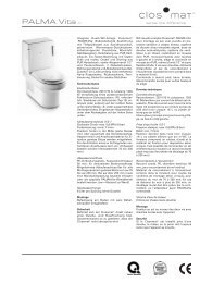
Sie haben ein Original-Dusch-WC CLOSOMAT PALMAVita vor sich. Unser gemeinsamer Kunde setzt grosse<br />
Erwartungen in <strong>die</strong>ses hochwertige Produkt, das unser Werk nach strengen Prüfungen verlassen hat. Wir als<br />
Hersteller sind Ihnen dankbar für Ihre sorgfältige <strong>Montage</strong>, damit der Kunde das Gerät in einwandfreiem<br />
Zustand in Besitz nehmen kann. Wenn Sie nach den folgenden Instruktionen vorgehen, montieren Sie den<br />
CLOSOMAT rasch und problemlos.<br />
Sorgen Sie bitte dafür, dass <strong>die</strong> <strong>Montage</strong> nur von Fachleuten mit ausreichenden allgemeinen Sanitär- oder<br />
speziellen CLOSOMAT-Kenntnissen ausgeführt wird, <strong>die</strong> zudem eine der drei in <strong>die</strong>ser Anleitung verwendeten<br />
Sprachen verstehen.<br />
Ihre Fragen beantwortet der für Ihr Land zuständige technische Dienst (siehe Rückseite) gerne.<br />
<strong>Wichtige</strong> <strong>Voraussetzungen</strong> für <strong>die</strong> <strong>erfolgreiche</strong> <strong>Montage</strong><br />
Entscheidender Informationsvorsprung<br />
Lesen Sie <strong>die</strong>se Anleitung vor <strong>Montage</strong>beginn vollständig durch, damit Sie <strong>die</strong> Zusammenhänge erkennen<br />
und Ihnen <strong>die</strong> nachfolgenden Arbeiten leichter fallen.<br />
Nicht zu früh montieren<br />
Den CLOSOMAT erst montieren, wenn sämtliche anderen Handwerker (Gipser, Maler, Fliesenleger usw.) ihre<br />
Arbeiten beendet haben. Dies vermeidet Beschädigungen wie Kratzer und Missbrauch des CLOSOMAT als<br />
«Ausguss» oder als «Bautoilette».<br />
Lieferung kontrollieren<br />
Kontrollieren anhand der Angaben auf dem Etikett auf der Verpackung, ob Modell, Farbe und Ausführung der<br />
Bestellung entsprechen.<br />
Anschlüsse kontrollieren<br />
• Elektro-Anschluss<br />
– Kontrollieren, ob Spannung vorhanden und der Stromkreis mit einer Fehlerstromsicherung (FI) versehen<br />
ist.<br />
– Kontrollieren, ob <strong>die</strong> Sicherheitsabstände (Schutzbereiche) zu den anderen Sanitäreinrichtungen den<br />
gültigen Vorschriften entsprechen.<br />
• Wasser-Anschluss (nur Kaltwasser erforderlich!)<br />
Kontrollieren, ob <strong>die</strong> Netzförderleistung mindestens 7 Liter pro Minute und der statische Dauerdruck<br />
maximal 0,8 MPa (8 bar) betragen.<br />
3
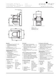
Prüfen, ob Planmasse mit den bauseitigen Massen übereinstimmen<br />
• Den gefalteten Teil der hinteren Umschlagseite <strong>die</strong>ser Installationsanleitung einmal nach rechts entfalten,<br />
so dass <strong>die</strong> Seite mit der ersten Abbildungsserie rechts neben den Textseiten sichtbar ist.<br />
• Vergleichen der Planmasse (Bild 1) mit den bauseitigen Massen.<br />
Plan- und bauseitige Masse stimmen überein:<br />
Apparat mit dem mitgelieferten Anschlussmaterial anschliessen.<br />
Plan- und bauseitige Masse stimmen nicht überein:<br />
Erforderliche Anpassungen vornehmen.<br />
Für folgende Fälle ist geeignetes Material ab Lager lieferbar:<br />
• Wasseranschluss (hinten in der Mitte) ist zu tief:<br />
– CLOSOMAT Spezial-Wasseranschluss-Set für einen Versatzbereich von 70 bis 230 mm verwenden.<br />
Bestellnummer 00-0924-00.<br />
– Eingriffe am Spülkasten, wie Anbringen von Ausschnitten, welche <strong>die</strong> Überlaufhöhe herabsetzen,<br />
sind zu unterlassen.<br />
• Mittelachse des Bodenablauf-Anschlusses ist mehr als 250 mm von der Wand entfernt:<br />
Aus Sicherheitsgründen darf der Abstand zwischen der Wand und dem hinten offenen Apparat nicht mehr<br />
als 10 mm sein! Es kommen deshalb folgende 2 Möglichkeiten in Frage:<br />
Variante 1:<br />
Veranlassen, dass bauseitig eine entsprechende nassfeste Wandaufdoppelung vorgenommen wird<br />
(beschichtetes Holz oder Gipsplatten usw.).<br />
Variante 2:<br />
Die spezielle Rückwand Typ PalmaVita bestellen.<br />
• Horizontalablauf vorhanden:<br />
Mittelachse des Horizontalablaufes ist maximal 220 mm über dem Boden:<br />
– CLOSOMAT PalmaVita direkt anschliessen.<br />
Mittelachse des Horizontalablaufes ist höher als 220 mm über dem Boden: Folgende Varianten sind<br />
möglich:<br />
Variante 1:<br />
Zusätzliche Sockel montieren gemäss den Instruktionen unter dem untenstehenden Titel «Sitzhöhe ist<br />
gemäss den Anforderungen des Benutzers zu gering».<br />
Variante 2:<br />
Anstelle des Modells PalmaVita den wandhängenden CLOSOMAT LimaVita montieren, sofern <strong>die</strong> Rück<br />
wand ausreichend tragfähig ist.<br />
Sitzhöhe ist gemäss den Anforderungen des Benutzers zu tief<br />
Die Sitzhöhe des CLOSOMAT PalmaVita ist 430 mm. Falls der Benutzer eine grössere Sitzhöhe wünscht, gibt<br />
es folgende Möglichkeit:<br />
• Montieren eines CLOSOMAT Zusatzsockels (Typ Palma).<br />
4
Auspacken und Vorbereiten des Gerätes<br />
• Die Seite mit der ersten Abbildungsserie <strong>die</strong>ser Installationsanleitung soll für <strong>die</strong> folgenden Instruktionen<br />
rechts neben den Textseiten sichtbar sein. Hierzu muss der gefaltete Teil der hinteren Umschlagseite ein<br />
mal nach rechts umgelegt sein.<br />
• Verpackungsteile, ausser den Plastikhüllen der Sitzgarnitur, wegnehmen. Ganze Sitzgarnitur (mit steckbaren<br />
Scharnierköpfen an der Schüssel befestigt) bis zum Schluss der Arbeiten zur Seite stellen:<br />
Deckel öffnen, mit beiden Daumen an <strong>die</strong> Scharnierkopf-Innenseite greifen, mit den Fingern den Sitzring<br />
festhalten und gleichmässig mit einem kleinen Ruck senkrecht nach oben ziehen (Bild 2).<br />
• Allfällige Transportschäden umgehend dem letzten Frachtführer melden.<br />
Achtung: Verpackung aufbewahren, bis alles mitgelieferte <strong>Montage</strong>-Material ausgepackt ist<br />
(Ablaufverbindung, Schrauben und allfälliges Spezialzubehör).<br />
• Bereitstellen einer weichen Unterlage (eventuell Verpackungskarton verwenden)<br />
• Apparat vorne am Porzellan-Spülrand und hinten am Stahlrahmen fassen und aus dem Verpackungsboden<br />
heben (Bild 3).<br />
Achtung: Apparat nicht an Verschalungsteilen hochheben.<br />
• Gerät vorsichtig auf weiche Unterlage abstellen, niemals umherschieben.<br />
• Die lackierten Oberflächen, wie Sitzdeckel und Spülkastenverschalung, sorgfältig behandeln. Diese sind<br />
nicht kratzfest. Deshalb nie als Werkzeugablage benutzen!<br />
• Die auf der Keramik liegende Prüfabdeckung (Bild 4), welche auch den Plastikumschlag mit den wichtigen<br />
Dokumenten für den Kunden (Be<strong>die</strong>nungsanleitung und Garantiekarte) enthält, wird später für <strong>die</strong><br />
Funktionskontrolle benötigt.<br />
• Dafür sorgen, dass Deckel und Dokumente schliesslich in <strong>die</strong> Hände der neuen Besitzer gelangen.<br />
• Die vorliegende Installationsanleitung dagegen ist nach dem Ausfüllen der Installationsmeldekarte zu<br />
entfernen!<br />
Spülkastenverschalung entfernen<br />
• Deckkappe an der Spülkastenverschalung vorsichtig lösen und herausziehen (Bild 5).<br />
• Die darunter liegende Schraube ganz herausdrehen (Bild 6).<br />
• Spülkastenverschalung leicht nach oben heben und dann nach vorne wegziehen (Bild 7).<br />
Untere Verschalung entfernen<br />
• Vordere Schraube lösen (Bild 8).<br />
• Die beiden Halteklammern hinten links und rechts nach oben schwenken (Bild 9).<br />
• Beidseitig <strong>die</strong> hinteren Verschalungs-Seitenlappen vorsichtig etwas nach aussen spreizen und dann<br />
<strong>die</strong> untere Verschalung nach vorne wegschieben (Bild 10).<br />
5
<strong>Montage</strong>-Vorbereitungen<br />
• Alle <strong>Montage</strong>-Arbeiten sind bei ausgezogenem Netzstecker auszuführen!<br />
Ablauf vorbereiten:<br />
• Die dem mitgelieferten Anschluss-Set (DN 80) beiliegende, separate Anleitung zur Hand nehmen.<br />
• Herstellen des Verbindungsbogens gemäss Anleitung entsprechend der Lage des Ablaufs im Bereich<br />
von 70 bis 250 mm Wandabstand (verschweissen mit dem üblichen Spiegelschweiss-Gerät).<br />
• Unteres Rohrende am fertiggestellten und abgelängten Ablaufbogen vor dem Anbringen der Kittmasse<br />
sauber entfetten und falls möglich mit Klebe-Primer vorbehandeln.<br />
• Gerät provisorisch an seinen Standort stellen und genau ausrichten.<br />
• Wenn <strong>die</strong> Mittelachse des Ablaufanschlusses maximal 250 mm von der Wand entfernt ist:<br />
Rückwärtige Distanzschrauben im Rahmen so weit herausdrehen, dass <strong>die</strong> Schraubenköpfe <strong>die</strong> Wand<br />
berühren (Bild 11).<br />
• Wenn <strong>die</strong> Mittelachse des Ablaufanschlusses mehr als 250 mm von der Wand entfernt ist:<br />
Gerät entsprechend nach vorne rücken. Die Köpfe der Distanzschrauben berühren in <strong>die</strong>sem Fall <strong>die</strong><br />
Wand nicht.<br />
– Mit der Wasserwaage kontrollieren, ob das Gerät gerade steht (Bild 12).<br />
– Ausgleichen allfälliger Bodenunebenheiten mit den Stellschrauben am Rahmenunterteil (Bild 11).<br />
– Stellschrauben mit Muttern sichern.<br />
– Auf dem Boden <strong>die</strong> beiden Bohrlöcher markieren (Bild 13).<br />
– Apparat wieder zur Seite stellen.<br />
– Bohren der Dübellöcher (12 mm) bei den beiden Markierungen (Bild 14).<br />
Vorsicht: Es könnten Leitungen oder Heizregister im Boden verlegt sein!<br />
– Die mitgelieferten Bolzendübel einsetzen und festziehen.<br />
Kaltwasseranschluss<br />
Mitgeliefertes Material: Absperrventil 1 / 2 " und Flexschlauch<br />
Achtung: Sicherstellen, dass das fertig montierte Absperrventil nicht mehr als 60 mm aus<br />
der Wand herausragt, damit es keine beweglichen Teile des Spülmechanismus berührt.<br />
• Höhe des bauseitigen Anschlusses über dem Fertig-Fussboden messen und je nach Situation wie folgt<br />
vorgehen:<br />
– Wenn der Anschluss 820 bis 830 mm über dem Fertig-Fussboden liegt (Bild 15):<br />
Weiter bei: «Apparat installieren».<br />
– Wenn der Anschluss zu tief liegt:<br />
Etage mit Original-Umbauset gemäss der dem Material beiliegenden Instruktion installieren<br />
(Bilder 16 und 17).<br />
Achtung: Keine Ausschnitte am Spülkasten anbringen, weil sonst <strong>die</strong> Überlaufhöhe<br />
unterschritten werden könnte.<br />
Danach weiter bei: «Apparat installieren».<br />
– Wenn der Anschluss ausserhalb des Gerätebereiches liegt:<br />
Verbindung mit verchromtem Kupferrohr 8 x 10 mm erstellen (Bild 18).<br />
Zuerst senkrecht nach unten fahren, dann horizontal führen und schliesslich auf der Mittelachse des<br />
Gerätes der Wand entlang hochfahren.<br />
6
Apparat installieren<br />
• Ablaufmuffe im Boden reinigen, trockenreiben und sauber entfetten, damit <strong>die</strong> Kittmasse einwandfrei<br />
haftet! (Bild 19)<br />
• Befestigungsbügel hochschwenken (Bild 20).<br />
• Vorbereitete Ablaufverbindung am Gerät montieren.<br />
• Befestigungsbügel wieder nach unten klappen und mit den Flügelmuttern nur von Hand festziehen<br />
(Bild 21).<br />
• Gerät mit vormontiertem Ablaufbogen zum Standort tragen.<br />
• Ablaufverbindung in Bodenanschluss einfahren und unter leichtem Druck vorsichtig absenken, gleichzeitig<br />
darauf achten, dass Rahmenlöcher auf Bodenbefestigungsbolzen ausgerichtet sind (Bild 22).<br />
• Den Sitz des Ablaufbogens am Gerät und im Boden kontrollieren:<br />
Wenn Kitt verwendet wurde: Kitt von Hand rund herum kräftig andrücken.<br />
Achtung: Um Geruchsbelästigung und Korrosionsschäden zu vermeiden, ist absolute<br />
Dichtheit erforderlich!<br />
• Distanzstücke, Unterlegscheiben und Muttern auf Befestigungsbolzen anbringen. Apparat festschrauben.<br />
Absperrventil<br />
Wenn das Absperrventil direkt in den Wandanschluss oder in <strong>die</strong> Etage eingedreht werden kann:<br />
• Absperrventil einschrauben (Bild 23).<br />
• Verbindung zwischen Füllventil und Absperrventil herstellen (Bild 24).<br />
Wenn nach dem Absperrventil ein Kupferrohr oder ein Flexschlauch montiert werden musste:<br />
• Verbindung zwischen Kupferrohr (Quetschverschraubung) oder langem Flexschlauch herstellen.<br />
• Eventuell Kaltwasserleitung spülen, um zu verhindern, dass das Füllventil des Gerätes durch Schmutzpartikel<br />
verstopft wird:<br />
Beim vorsichtigen Öffnen des Absperrventils mit der Hand den Wasserstrahl abschirmen und in den Spülkasten<br />
ablenken, damit <strong>die</strong> Elektrik trocken bleibt.<br />
7
Inbetriebnahme / Funktionskontrolle<br />
Spülsystem<br />
• Absperrventil öffnen.<br />
• Kontrollieren, ob Wasserstand im Spülkasten ungefähr auf 6-Liter-Marke oder leicht darüber, jedoch<br />
keinesfalls tiefer ist (Bild 25). Falls erforderlich, Wasserstand regulieren mittels Drehen des Schaumstoff-<br />
Schwimmkörpers (Bild 26).<br />
• Spülung drei-/viermal betätigen und alle Verbindungsstellen bei Wasserzuleitung und Ablaufanschluss auf<br />
Dichtigkeit überprüfen.<br />
Duschsystem<br />
• Links unten befindet sich ein kleines Spezialwerkzeug (Bild 27).<br />
• Werkzeug herausziehen und gemäss Bild 28 mit der spitzen Seite von unten in das Düsenloch einfahren<br />
und <strong>die</strong> Düse herausziehen.<br />
• Düse mit der anderen Hand ergreifen und vorne halten – Werkzeug umdrehen und von oben auf <strong>die</strong> ring<br />
förmige Kerbe hinten an der Düse stecken (Bild 29) – <strong>die</strong> Düse bleibt nun ausgefahren.<br />
• Die mitgelieferte transparente Prüfabdeckung auf <strong>die</strong> Keramikschüssel legen, damit der Duschstrahl bei<br />
der Inbetriebnahme abgeschirmt wird (Bild 34).<br />
Elektrisch:<br />
• Prüfen, ob vorhandene Netzspannung der Angabe auf dem Typenschild entspricht<br />
(untere Verschalung rechts)!<br />
• Netzkabel in Dose einstecken.<br />
Vorsicht: Der Apparat steht jetzt unter Spannung: Sicherstellen, dass keine<br />
stromführenden Teile berührt werden. Arbeiten nur bei gezogenem Netzstecker.<br />
Die folgenden 2 Schritte haben zügig nacheinander zu erfolgen, damit <strong>die</strong> Boilerheizung nicht<br />
trocken läuft :<br />
• Hauptschalter einschalten, indem der Kippschalter oben gedrückt wird (Bild 30).<br />
• Dusche betätigen: Mit der einen Hand linkes Sitzringscharnier nach unten drücken (Leuchtdiode A, Bild 39,<br />
beginnt zu leuchten) und mit der anderen Hand auf <strong>die</strong> linke oder rechte Lasche des Auslösegestänges<br />
drücken (Bild 34). Die Normalspülung erfolgt und gleichzeitig startet <strong>die</strong> Pumpe für das Duschsystem. Es<br />
dauert eine gewisse Zeit bis der Boiler gefüllt ist und <strong>die</strong> Dusche beginnt. Sitzringscharnier und Gestänge<br />
gedrückt halten bis der Duschstrahl gleichmässig (ohne Lufteinschlüsse) ist.<br />
• Duschvorgang abbrechen, Prüfabdeckung entfernen.<br />
• Mit der einen Hand Düse ergreifen, mit der anderen Hand das Spezialwerkzeug entfernen und Düse<br />
zurückfahren lassen. Werkzeug in seine Halterung zurück stecken (Bild 35).<br />
• Prüfabdeckung erneut auflegen und den Duschvorgang wie oben wiederholen, wobei jetzt <strong>die</strong> Düse<br />
selbsttätig aus- und nach Loslassen des Gestänges wieder einfährt und mit einem gezielten<br />
Wasserstrahl gereinigt wird.<br />
8
Kontrollen:<br />
• Sollte bei belastetem Sitzringscharnier <strong>die</strong> Leuchtdiode (A, Bild 39), auf der Elektronik nicht aufleuchten,<br />
ist <strong>die</strong> Stromzufuhr zum Gerät zu überprüfen.<br />
• Die rote Leuchtdiode „Boiler“ auf der Elektronik (Bild 31) zeigt den Heizvorgang an. Sie erlischt bei Errei<br />
chen der gewünschten Temperatur (nach ca. 3 -4 Minuten). Falls das Gerät auf Kundenwunsch auf „Boiler-<br />
Sparschaltung“ eingestellt ist, findet der Heizvorgang nur bei belastetem Sitzringscharnier statt (Bild 32).<br />
Sollte <strong>die</strong> Leuchtdiode „Boiler“ bei erwartetem Heizvorgang nicht aufleuchten oder blinken, auch nicht bei<br />
belastetem Sitzringscharnier, ist wie folgt vorzugehen:<br />
– Reset-Knopf am Sicherheitstemperaturbegrenzer drücken (Bild 33). Falls kein Erfolg, Stromzufuhr zum<br />
Gerät überprüfen.<br />
• Stromzufuhr zum Gerät überprüfen: Hauptschalter ausschalten. Kontrollieren ob Netzstecker richtig in der<br />
Dose steckt, Steckdose unter Spannung steht und Sicherung im Haus-Sicherungskasten sowie Fehler<br />
stromschalter in Ordnung sind. Hauptschalter wieder einschalten. Im Zweifelsfall Elektriker beiziehen.<br />
• Sollte der Duschstrahl wegen Lufteinschlüssen dauernd unregelmässig bleiben, Wasserzufuhr überprüfen.<br />
Der Spülkasten sollte mit mind. 7 Liter/Minute gespiesen werden. Falls <strong>die</strong>ser Füllvorgang auch nach allfäl<br />
ligem Entfernen von Schmutzpartikeln (durchspülen) ungenügend bleibt, beispielsweise bei Fliessdruck<br />
deutlich unter 0,15 Mpa (1,5 bar), kann am Füllventil <strong>die</strong> blaue Drossel hinter der grossen Schraubkappe<br />
entfernt werden (Bild 36) – <strong>die</strong> Schraubkappe darf beim Wiederanbringen nur von Hand (ohne Werkzeug!)<br />
angezogen werden. Es ist zu beachten, dass <strong>die</strong>se Massnahme höhere Schallemissionen bewirkt!<br />
9
Reguliermöglichkeiten / Einstellungen (auf speziellen Kundenwunsch)<br />
Duschstrahl verstärken<br />
Wird seitens der Kundschaft eine generelle Erhöhung/Verminderung des eingestellten Grunddruckes<br />
gewünscht, kann <strong>die</strong>s mittels Stellschraube am Pumpenhebel geschehen (Bild 37): Drehen im Uhrzeigersinn<br />
bewirkt Verstärkung, im Gegenuhrzeigersinn Verminderung der Strahlstärke.<br />
Tippbetätigung<br />
Normalerweise duscht CLOSOMAT solange, wie eine Ellbogentaste gedrückt wird. Soll jedoch der Funktionsablauf<br />
nach kurzem Antippen einer Ellbogentaste automatisch geschehen, dann kann <strong>die</strong> gewünschte<br />
Duschdauer eingestellt werden. Dazu ist der Drehschalter „Tipp-Time“ (C, Bild 39), mit kleinem Schraubenzieher<br />
im Uhrzeigersinn von der Basisstellung „0“ aufzudrehen, wobei <strong>die</strong> Veränderung pro Schritt ca. 3<br />
Sekunden beträgt. Z.B. entspricht <strong>die</strong> Position 3 ca. 9 Sek., Pos. 5 ca. 15 Sek., <strong>die</strong> Pos. 8 ca. 24 Sek., usw.<br />
Trennung der Tastenfunktionen<br />
CLOSOMAT ist aufgrund jahrzehntelanger Erfahrung so konstruiert, dass beim Auslösen der Dusche durch<br />
Tastendruck automatisch auch <strong>die</strong> Klosettschüssel gespült wird.<br />
Auf Wunsch des Kunden können <strong>die</strong>se Vorgänge jedoch mit folgendem Eingriff getrennt werden:<br />
Die kleine Sperrschraube (Bild 38) im Auslösegestänge entfernen und das Gestänge anschliessend auf freie<br />
Beweglichkeit prüfen (eventuell gängig machen). Somit kann jetzt <strong>die</strong> Normalspülung nur noch mit der von<br />
vorne gesehen rechten Taste betätigt werden und über <strong>die</strong> linke Taste wird bei gleichzeitig belastetem Sitzring<br />
<strong>die</strong> Dusche allein ausgelöst.<br />
Wassertemperatur<br />
Auf der Elektronik kann oben am Drehschalter „Wassertemperatur“ (D, Bild 39), <strong>die</strong> standardmässig auf<br />
37-38 °C eingestellte Duschwasser-Temperatur reguliert werden. Drehen im Uhrzeigersinn bewirkt höhere,<br />
im Gegenuhrzeigersinn tiefere Temperatur. Drehen um +/- 1 Schritt auf der Skala ergibt eine Veränderung<br />
von +/- ca. 0,4 °C (max. 40°C)<br />
Boiler-Sparschaltung<br />
Normalerweise hält CLOSOMAT den Boiler stets auf Körpertemperatur. Alternativ kann jedoch <strong>die</strong><br />
„Sparschaltung“ aktiviert werden. Dazu wird der Minischalter No 2 (B, Bild 39) auf <strong>die</strong> Position „on“<br />
geschoben. Jetzt beginnt der Boiler jeweils erst nach Belastung des Sitzringes aufzuheizen, womit der<br />
Benutzer erst nach ca. 3 Minuten körperwarm duschen kann. Diese Funktion eignet sich auch für eher<br />
selten benutzte Geräte.<br />
10
Kontrollen vor dem Anbringen der Verschalung<br />
• Nochmals gründliches Überprüfen, ob Verbindungsstellen am wasserführenden System dicht sind.<br />
• Prüfen, ob beim Spülen der ganze Zugmechanismus über den Umlenkhebel auf das Auslassventil frei<br />
spielt, ohne das Absperrventil oder den Verbindungsschlauch zu streifen.<br />
• Prüfen, ob <strong>die</strong> Bodenverschraubung noch festsitzt und sich kein Dübel gelockert hat.<br />
Verschalungen montieren<br />
• Untere Verschalung vorsichtig von vorn nach hinten schiebend einfahren und in richtige Position rücken,<br />
wobei <strong>die</strong> hinteren Nocken seitlich rechts und links im Rahmen einrasten müssen (Bild 40).<br />
Achtung: Die Verschalungsteile sind schlagempfindlich!<br />
• Die beiden Halteklammern hinten links und rechts wieder ganz herunterklappen (Bild 41).<br />
• Schraube einsetzen und nur mässig anziehen (Bild 42).<br />
• Spülkastenverschalung von vorne her vorsichtig einfahren und richtig positionieren (Bild 43).<br />
• Schraube einsetzen und mässig anziehen (Bild 44).<br />
• Deckkappe wieder einsetzen (Position gemäss Kerbe beachten) (Bild 45).<br />
• Sitzgarnitur montieren und sicherstellen, dass <strong>die</strong> Bolzen der Scharnierköpfe vollständig in <strong>die</strong> Hülsen ein<br />
fahren (Bild 46).<br />
11
Funktionskontrolle<br />
Hauptschalter<br />
• Prüfen, ob Hauptschalter eingeschaltet und Abdeckung montiert ist (Bild 47).<br />
Tastenspiel<br />
• Prüfen, ob beide Ellbogentasten einen kurzen freien Weg aufweisen, bevor sie durch das Eingreifen in das<br />
Auslösegestänge mehr Widerstand bieten.<br />
Dusch-WC-Funktion<br />
• Prüfabdeckung auflegen und Sitzring herunterklappen (Bild 48).<br />
• Mit der einen Hand Scharniere belasten und eine der beiden Tasten drücken. Die Klosettspülung und <strong>die</strong><br />
Dusche treten in Aktion (Bild 48), ausser bei auf Kundenwunsch getrennter Tastenfunktion.<br />
• Nach etwa 10 Sekunden bei weiter belasteten Scharnieren <strong>die</strong> Taste loslassen. Die Warmlufttrocknung setzt ein.<br />
• Bei erneut belastetem Sitzring <strong>die</strong> andere Taste drücken: Spülung und Dusche setzen ein, ausser bei auf<br />
Kundenwunsch getrennten Tastenfunktionen. Nach ca. 10 Sekunden loslassen und Einsetzen der Warmluft<br />
abwarten.<br />
• Wenn <strong>die</strong>se Vorgänge erfolgreich abgelaufen sind, Gerät und Prüfabdeckung mit sauberem, weichem<br />
Lappen trockenreiben.<br />
Schlussarbeiten vor dem Verlassen des <strong>Montage</strong>platzes<br />
• Falls Kundschaft anwesend ist:<br />
Apparat «übergeben» und kurz <strong>die</strong> wichtigsten Be<strong>die</strong>nungselemente erklären. Überreichen der Prüfabdeckung<br />
mit Hinweis auf ausführliche Be<strong>die</strong>nungsanleitung und beiliegende Garantiekarte zum Ausfüllen<br />
(durch den Kunden!).<br />
• Falls Kunde nicht anwesend ist:<br />
Unbedingt sicherstellen, dass <strong>die</strong> Prüfabdeckung und <strong>die</strong> Be<strong>die</strong>nungsanleitung zu gegebener Zeit in <strong>die</strong><br />
Hände der Kunden kommen.<br />
Füllen Sie bitte <strong>die</strong> <strong>die</strong>ser <strong>Montage</strong>anleitung beigelegte Installations-<br />
Meldekarte vollständig aus und senden Sie <strong>die</strong>se zurück.<br />
Wir bedanken uns herzlich für Ihren Beitrag zu einer erstklassigen Be<strong>die</strong>nung unserer gemeinsamen Kundschaft.<br />
12
Cher spécialiste sanitaire, cher partenaire<br />
Vous avez un CLOSOMAT PALMAVita WC-douche original devant vous. Notre client commun met de gros<br />
espoirs dans ce produit de haute qualité qui a quitté notre usine après de sévères essais. Nous, en qualité de<br />
fabricants, vous sommes reconnaissants de votre montage soigné afin que le client puisse prendre possession<br />
de l’appareil dans un état irréprochable. Si vous procédez conformément aux instructions qui suivent,<br />
vous monterez le CLOSOMAT rapidement et sans problème.<br />
Veillez à ce que le montage soit exécuté par des professionnels ayant suffisamment de connaissances<br />
en sanitaire ou spéciales CLOSOMAT qui, de plus, comprennent l’une des troi langues utilisées dans ce guide.<br />
Le service technique compétent pour votre pays répondra à vos questions (voir page au verso).<br />
Conditions préalables importantes pour un montage réussie<br />
Emportance décisive de s’informer d’abord<br />
Lisez complètement ce guide avant de commencer le montage afin que vous puissiez reconnaître les<br />
rapports qui vous rendront ensuite la tâche plus facile.<br />
Ne pas monter trop tôt<br />
Ne monter le CLOSOMAT que lorsque tous les autres artisans (plâtrier, peintres, carreleurs, etc.) ont terminé<br />
leurs travaux. Ceci évite des dégâts, tels qu’égratignures et le mauvais usage du CLOSOMAT comme «évier»<br />
ou «toilette de chantier».<br />
Contrôler la fourniture<br />
Contrôler à l’aide des indications figurant sur l’étiquette placée sur l’emballage si le modèle, la couleur et la<br />
version correspondent à la commande.<br />
Contrôler les raccordements<br />
• Raccordement électrique<br />
– Contrôler si la tension est là et si le circuit électrique est muni d’un déclencheur par courant de défaut.<br />
– Contrôler si les distances de sécurité (zones de protection) aux autres installations sanitaires sont con<br />
formes aux prescriptions en vigueur.<br />
• Raccordement d’eau (uniquement eau froide requise!)<br />
Contrôler si le débit de réseau est d’au moins 7 litres par minute et la pression statique permanente de<br />
0,8 MPa (8 bar) au maximum.<br />
15
Vérifier si les cotes du plan coïncident avec celles de construction<br />
• Déplier à droite la partie pliée de la page de derrière de couverture de ce guide d’installation de manière<br />
à rendre visible la première série d’illustrations placée à droite des pages de texte.<br />
• Comparer les cotes du plan (figure 1) avec celles de la construction.<br />
Cotes du plan et de la construction coïncident:<br />
Raccorder l’appareil à l’aide du matériel livré à cet effet.<br />
Cotes du plan et de la construction ne coïncident pas:<br />
Procéder aux ajustements nécessaires.<br />
Le matériel adéquat est disponible départ magasin pour les cas suivants:<br />
• Raccord d’eau (derrière au milieu) trop bas:<br />
– Utiliser le jeu de raccords d’eau spéciaux CLOSOMAT pour des déports allant de 70 à 230 mm.<br />
Numéro de commande 00-0924-00.<br />
– Ne pas procéder à des interventions sur le réservoir de chasse, telles que faire des découpes qui abais<br />
seraient le trop-plein.<br />
• L’axe du raccord d’écoulement au sol est situé à plus de 250 mm de la paroi:<br />
Pour des raisons de sécurité, la distance entre la paroi et l’appareil ouvert à l’arrière ne doit pas être<br />
supérieure à 10 mm. C’est la raison pour laquelle il ne peut y avoir que les deux possibilités suivantes:<br />
Variante 1:<br />
Veillez à ce que la construction procède à un doublage approprié de la paroi, qui résiste à l’état humide<br />
(bois revêtu, plaques de plâtre, etc.).<br />
Variante 2:<br />
Commander la face arrière de sécurité type PalmaVita.<br />
• Présence d’un écoulement horizontal:<br />
L’axe de l’écoulement horizontal se trouve au maximum à 220 mm au-dessus du sol:<br />
– Raccorder directement le CLOSOMAT PalmaVita.<br />
L’axe de l’écoulement horizontal se trouve à plus de 220 mm au-dessus du sol:<br />
Il est possible de réaliser les deux variantes suivantes:<br />
Variante 1:<br />
Monter un socle supplémentaire, conformément aux instructions du titre ci-dessous «La hauteur du siège<br />
est insuffisante selon les exigences de l’utilisateur».<br />
Variante 2:<br />
A la place du modèle PalmaVita installer le CLOSOMAT mural LimaVita, dans la mesure où la paroi arrière<br />
est suffisamment porteuse.<br />
La hauteur du siège est insuffisante selon les exigences de l’utilisateur<br />
La hauteur du siège du CLOSOMAT PalmaVita est de 430 mm. Si l’utilisateur souhaite une hauteur du siège<br />
plus grande, il y a la possibilité suivante:<br />
• <strong>Montage</strong> d’un socle supplémentaire CLOSOMAT (type Palma).<br />
16
Déballage et préparation de l’appareil<br />
• La page contenant la première série d’illustrations de ce guide d’installation doit être visible à droite<br />
des pages de texte pour les instructions qui suivent. A cet effet, la partie pliée de la page de derrière de<br />
couverture doit être tournée une fois à droite.<br />
• Enlever les parties d’emballage, sauf l’enveloppe en plastique du siège et couvercle. Mettre de côté toute<br />
siège et couvercle (avec têtes de charnière enfichables fixées à la cuvette) jusqu’à la fin des travaux:<br />
relever le couvercle, saisir avec les deux pouces à l’intérieur des têtes de charnière, tenir le siège avec les<br />
doigts et tirer le tout verticalement vers le haut, en donnant un léger coup (figure 2).<br />
• Signaler sans délai tous les dégâts de transport éventuels au dernier voiturier.<br />
Attention: conserver l’emballage jusqu’à ce que tout le matériel de montage livré soit<br />
déballé (jonction d’écoulement, vis et accessoires spéciaux éventuels).<br />
• Mettre en place un dessous doux (utiliser, le cas échéant, le carton d’emballage).<br />
• Saisir l’appareil devant au bord de chasse en porcelaine et derrière au cadre en acier et le soulever hors<br />
du fond de l’emballage (figure 3).<br />
Attention: ne pas soulever l’appareil par les parties du revêtement.<br />
• Poser l’appareil avec précaution sur le dessous doux, ne jamais le traîner.<br />
• Manipuler avec soin les surfaces vernies, telles que couvercle du siège et revêtement du réservoir de<br />
chasse. Elles sont sensibles aux égratignures. En conséquence, ne jamais poser d’outils dessus!<br />
• Le couvercle de contrôle placé sur la céramique (figure 4) qui contient également l’enveloppe en plastique<br />
avec les documents importants pour le client (notice d’emploi et carte de garantie) sera utilisé plus tard<br />
pour contrôler le fonctionnement.<br />
• Veiller à ce que couvercle et documents parviennent finalement dans les mains de nouveaux possesseurs.<br />
• Par contre, le présent guide de montage doit être retiré une fois que la carte d’enregistrement d’installation<br />
a été remplie!<br />
Enlever le revêtement du réservoir de chasse<br />
• Desserrer avec précaution la calotte du revêtement et la sortir (figure 5).<br />
• Dévisser complètement la vis qui se trouve dessous (figure 6).<br />
• Soulever légèrement le revêtement du réservoir de chasse vers le haut, puis le tirer vers l’avant (figure 7).<br />
Enlever le revêtement inférieur<br />
• Desserrer la vis de devant (figure 8).<br />
• Faire pivoter vers le haut les deux étriers de retenue à gauche et à droite (figure 9).<br />
• Ecarter des deux côtés avec précaution, un peu vers l’extérieur, les deux pattes latérales arrière, puis<br />
repousser vers l’avant le revêtement inférieur (figure 10).<br />
17
Préparatifs de montage<br />
• La fiche de prise de courant doit être retirée lors de la réalisation de tous les travaux de montage.<br />
Préparation de l’écoulement<br />
• Prendre en main les instructions séparées, qui sont jointes au set de raccordement (DN 80) fourni avec<br />
la livraison.<br />
• Fabriquer un coude de jonction conforme aux instructions, en fonction de la position de l’écoulement, qui<br />
est placé à une distance de 70 à 250 mm à partir de la paroi (soudage par «miroir chauffant»).<br />
• Nettoyer soigneusement l’extrémité inférieure du tube, sur le coude d’écoulement préparé et mis à<br />
longueur, avant d’appliquer le mastic, et si possible la traiter préalablement au moyen d’une couche de<br />
fond pour collage.<br />
• Placer provisoirement l’appareil sur son lieu de montage, et l’aligner de manière précise.<br />
• Si la distance entre l’axe du raccord d’écoulement et la paroi est au maximum de 250 mm<br />
Dévisser les vis d’écartement à l’arrière du cadre, de façon à ce que les têtes de vis touche la paroi<br />
(figure 11).<br />
• Si la distance entre l’axe du raccord d’écoulement et la paroi est supérieure à 250 mm<br />
Déplacer l’appareil en conséquence vers l’avant. Dans ce cas, les vis d’écartement ne touchent pas<br />
la paroi.<br />
– Contrôler à l’aide du niveau à bulle d’air si l’appareil est en position verticale (figure 12).<br />
– Compenser les éventuelles inégalités du sol au moyen des vis de réglage placées dans le socle du<br />
cadre (figure 11).<br />
– Assurer les vis de réglage au moyen des écrous.<br />
– Marquer sur le sol les deux trous à percer (figure 13).<br />
– Remettre l’appareil sur le côté.<br />
– Percer les trous de chevillage (12 mm) au niveau des deux marquages (figure 14).<br />
Attention: des conduites ou des registres de chauffage peuvent être intégrés dans le sol!<br />
– Introduire les chevilles à tige fournies avec la livraison, et serrer.<br />
Raccordement de l’eau froide<br />
Matériel fourni: robinet d’arrêt 1 / 2 " et tuyau flexible blindé<br />
Attention: s’assurer que le robinet d’arrêt définitivement monté ne dépasse pas de la paroi de<br />
plus de 60 mm afin qu’il ne touche aucune pièce mobile du mécanisme de chasse.<br />
• Mesurer la hauteur du raccordement de construction placé au-dessus du sol terminé, et procéder comme<br />
suit en fonction de la situation:<br />
– Si le raccord se trouve à une distance comprise entre 820 et 830 mm au-dessus du sol terminé<br />
(figure 15):<br />
Continuer comme dans: «Installation de l’appareil».<br />
– Si le raccord est trop bas:<br />
Installer un étage avec le jeu de transformation original conformément à l’instruction jointe au matériel<br />
(figures 16 et 17).<br />
Attention: ne pas faire de découpe sur le réservoir de chasse, autrement la hauteur de<br />
trop-plein pourrait être insuffisante.<br />
Continuer comme dans: «Installation de l’appareil».<br />
– Si le raccord se trouve en dehors de la portée de l’appareil:<br />
Etablir une jonction avec un tube en cuivre chromé 8 x 10 mm (figure 18).<br />
Aller d’abord verticalement vers le bas, puis passer à l’horizontale à travers le revêtement, puis<br />
finalement monter le long de la paroi, dans l’axe de l’appareil.<br />
18
Installation de l’appareil<br />
• Nettoyer l’embout d’écoulement au sol, l’essuyer à sec, et le dégraisser proprement, afin que le mastic<br />
adhère parfaitement! (figure 19).<br />
• Relever l’étrier de fixation (figure 20).<br />
• Monter sur l’appareil la jonction d’écoulement qui a été préparée (figure 21).<br />
• Rabattre l’étrier de fixation, et ne le serrer qu’à la main, au moyen des écrous à oreilles.<br />
• Après avoir monté le coude d’écoulement sur l’appareil, porter celui-ci au lieu de montage.<br />
• Introduire la jonction d’écoulement dans le raccord au sol, et la descendre avec précaution, en exerçant<br />
une légère pression. Parallèlement, veiller à ce que les trous du cadre soient alignés sur les tiges de<br />
fixation au sol (figure 22).<br />
• Contrôler si le coude d’écoulement est bien en place dans l’appareil et le sol:<br />
Si du mastic a été employé: Presser fortement le mastic à la main sur le pourtour.<br />
Attention: pour éviter la gêne due aux odeurs, ainsi que les dommages de corrosion, il est<br />
impératif d’avoir une étanchéité absolue!<br />
• Monter les pièces d’écartement, rondelles et écrous sur les tiges de fixation. Fixer l’appareil en serrant les<br />
écrous.<br />
Robinet d’arrêt<br />
Si le robinet d’arrêt peut être directement tourné dans le raccord mural ou dans l’étage:<br />
• Visser le robinet d’arrêt (figure 23).<br />
• Etablir la jonction entre le robinet de remplissage et celui d’arrêt (figure 24).<br />
S’il faut monter un tuyau de cuivre ou flexible blindé après le robinet d’arrêt:<br />
• Etablir la jonction entre le tuyau de cuivre (sertissage) ou un long tuyau flexible blindé.<br />
• Rincer éventuellement la conduite d’eau froide pour empêcher que la valve de remplissage de l’appareil<br />
soit obstrué par des particules de saleté:<br />
En ouvrant le robinet d’arrêt avec précaution, couvrir le jet d’eau avec le main et le dévier dans le réservoir<br />
de chasse afin que la partie électrique reste sèche.<br />
19
Mise en service / contrôle de fonctionnement<br />
Système de la chasse<br />
• Ouvrir le robinet d’arrêt.<br />
• Contrôler si le niveau d’eau dans le réservoir de chasse se trouve sur la marque 6 litres ou légèrement audessus,<br />
mais en aucun cas au-dessous (figure 25). Si nécessaire, régler le niveau d’eau par rotation du<br />
flotteur en mousse (figure 26).<br />
• Actionner la chasse deux/trois fois et vérifier l’étanchéité de tous les raccordements de la conduite d’eau<br />
de même qu’au raccord de l’écoulement.<br />
Système de la douche<br />
• A gauche en bas se trouve un petit outil spécial (figure 27).<br />
• Enlever l’outil et introduire le côté pointu à partir du dessous dans le trou de la buse selon figure 28<br />
et sortir la.<br />
• Saisir la buse de l’autre main et la maintenir devant – tourner l’outil et le mettre en place à partir du haut<br />
sur l’encoche annulaire de la buse (figure 29) – la buse reste dehors.<br />
• Mettre le couvercle de contrôle transparent (faisant partie de la fourniture) sur la cuvette afin que le jet<br />
d’eau soit couvert (figure 34).<br />
Electrique:<br />
• Vérifier si la tension de secteur présente correspond à celle indiquée sur la plaque signalétique (placée<br />
sur le revêtement inférieur derrière à droite)!<br />
• Brancher le câble dans la prise de courant.<br />
Attention: l’appareil est maintenant sous tension. S’assurer que des pièces conductrice<br />
de courant ne soient jamais touchées. Toujours couper le contact de l’appareil et retirer la<br />
fiche chaque fois que des travaux sont effectués !<br />
Les deux pas suivants doivent être réalisés l’un après l’autre sans arrêt, afin d’empêcher que le<br />
chauffage d’eau reste au sec:<br />
• Enclencher l’appareil par l’interrupteur principal en basculant le vers le haut (figure 30).<br />
• Actionner la douche comme suit: Presser d’une main la charnière gauche (la diode luminescente A, figure 39,<br />
s’allume) et de l’autre main presser sur la languette gauche ou droite de la tringlerie de déclenchement<br />
(figure 34). La chasse d’eau normale aura lieu et simultanément la pompe pour la douche commencera à<br />
travailler. Ca dure quelque secondes jusqu’à ce que le chauffe-eau soit rempli et la douche vient. Maintenir<br />
pressées la charnière et la tringlerie jusqu’à ce que le jet de douche soit régulier (sans inclusions d’air).<br />
• Interrompre le douchage, retirer le couvercle de contrôle.<br />
• Saisir la buse d’une main, retirer de l’autre l’outil spécial et laisser la buse se retirer en position de repos.<br />
Remettre l’outil dans son logement (figure 35).<br />
• Reposer le couvercle de contrôle de nouveau et répéter l’opération de douchage (voir en haut).<br />
Ce coup-ci la buse sort et se retire automatiquement et en se retirant est nettoyée par un jet d’eau<br />
bien dirigé.<br />
20
Contrôles:<br />
• Si sous pression de la charnière gauche la diode luminescente A, figure 39, sur l’électronique ne s’allume<br />
pas, vérifier la connexion de courant.<br />
• La diode luminescente rouge „chauffe-eau“ sur l’électronique (figure 31) indique le chauffage actif. Elle<br />
s’éteint après avoir atteindu la température (après env. 3 -4 minutes). Si l’appareil selon désire du client est<br />
réglé à „programme d’économie du chauffe-eau“, le chauffage est seulement activé par pression des<br />
charnières (figure 32). Si la diode luminescente « chauffe-eau » ne s’allume ou ne clignote pas, même<br />
avec pression sur la charnière gauche, procéder de la manière suivante:<br />
- Presser le bouton au limiteur de température de sécurité (figure 33). Si çan’aide pas, vérifier la connexi<br />
on de courant.<br />
• Vérifier la connexion de courant à l’appareil: Déclencher l’interrupteur principal. Controller si la fiche est<br />
correctement dans la prise, la prise est sous tension et le fusible domestique de même que le déclencheur<br />
par courant de défaut sont actifs. Enclencher l’interrupteur principal. En cas de doute appeler l’électricien.<br />
• Si le jet d’eau est toujours irrégulier (inclusions d’air), controller l’alimentation d’eau dans le réservoir de<br />
chasse qui devrait être au min. 7 litres par min. Si l’alimentation reste insuffisante, même après avoir rincé<br />
le système (saletés), par exemple avec une pression courante sous 0,15 Mpa (1,5 bar), il est possible d’en<br />
lever l’étranglement bleu placé derrière la grande calotte sur la valve de remplissage (figure 36) – en<br />
remettant la calotte elle se serre seulement à main (sans outil!). Il faut prendre en considération que cette<br />
mesure provoque plus de bruit en remplissant!<br />
21
Possibilités de réglage / ajustages (sur demande spéciale du client)<br />
Augmentation de la puissance du jet de douche<br />
Si le client désire une augmentation/réduction générale de la puissance de base ajustée, ceci peut se faire à<br />
l’aide de la vis de réglage placée sur le levier de pompe (figure 37): En tournant dans le sense horaire, la<br />
puissance du jet est augmentée, en sense inverse elle est diminuée.<br />
Déroulement automatique des fonctions<br />
Normalement le <strong>Closomat</strong> douche tant que l’une des deux touches cubitales est maintenue pressée. Si le<br />
déroulement des fonctions doit se réaliser automatiquement en pressant brièvement sur l’une des deux touches,<br />
avec une durée de douche réglable, procéder à la manière suivante : Tourner avec un petit tournevis le<br />
commutateur rotatif „Tipp-Time“ (C, figure 39), de sa position de base „0“ dans le sense horaire. Le changement<br />
de la durée de douche par pas sur le cadran gradué est env. 3 secondes. P.e. la position 3 sera env.<br />
9 sec., pos. 5 env. 15 sec, pos. 8 env. 24 sec., etc.<br />
Séparation des fonctions de touche<br />
CLOSOMAT est construit sur la base de dizaines d’années d’expérience de manière à ce qu’au déclenchement<br />
de la douche par pression de touche, la chasse d’eau a lieu simultanément.<br />
A la demande du client, ces opérations peuvent être séparées moyennant la petite intervention suivante:<br />
Retirer la petite vis d’arrêt de la tringlerie de déclenchement (figure 38). Vérifier ensuite la liberté de mouvement<br />
de la tringlerie (éventuellement la rendre mobile). La chasse d’eau normale ne peut maintenant être<br />
actionnée qu’avec la touche droite (vue de devant) et la douche sera déclenchée seule par la touche gauche,<br />
le siège étant simultanément chargé.<br />
Température de l’eau<br />
La température de l’eau est ajustée à la valeur standard d’env. 37-38 °C. Mais elle peut être réglée au commutateur<br />
rotatif « température d’eau » (D, figure 39), Tourner avec un petit tournevis dans le sense horaire<br />
augmente, en sense inverse réduit la température. Tourner +/-1 pas sur le cadran gradué donne un changement<br />
de +/- env. 0,4 °C (max. 40°C).<br />
Programme d’économie du chauffe-eau<br />
Normalement le CLOSOMAT maintient l’eau de la douche à la température du corps dans un chauffe-eau<br />
bien isolé. Alternativement le programme d’économie du chauffe-eau peut être activé par glisser le commutateur<br />
miniature no 2 (B, figure 39) sur la position « on ». Maintenant le chauffe-eau ne commence à chauffer<br />
que lorsque l’appareil est occupé et il faut attendre chaque fois env. 2-3 minutes jusqu’à ce que l’eau de la<br />
douche atteigne une température agréable. Cette fonction convient aussi pour des appareils rarement utilisés.<br />
Contrôles à faire avant de mettre le revêtement<br />
• Contrôler encore une fois si les connexions du système d’arrivée d’eau sont bien étanches.<br />
• Vérifier en tirant la chasse d’eau si tout le mécanisme de traction joue librement sur la valve de rinçage<br />
par le levier de renvoi, sans toucher le robinet d’arrêt ou le flexible de jonction.<br />
• Vérifier si les vis de fixation au sol sont encore bien serrées et si aucune cheville ne s’est relâchée.<br />
22
<strong>Montage</strong> des revêtements<br />
• Entrer le revêtement inférieur avec précaution en le glissant de l’avant vers l’arrière et le pousser en bonne<br />
position, les cames latérales arrière à droite et à gauche devant s’encliqueter dans le cadre (figure 40).<br />
Attention: les pièces de revêtement sont sensibles aux chocs!<br />
• Rabattre complètement les deux étriers de retenue à gauche et à droite à l’arrière (figure 41).<br />
• Introduire la vis et serrer modérément (figure 42).<br />
• Entrer précautionneusement le revêtement du réservoir de chasse par l’avant et le positionner<br />
correctement (figure 43).<br />
• Introduire la vis et serrer modérément (figure 44).<br />
• Remettre la calotte (position en fonction de l’encoche) (figure 45).<br />
• Monter le siège et le couvercle et s’assurer que les boulons des têtes de charnière entrent complètement<br />
dans les douilles (figure 46).<br />
Contrôle de fonctionnement<br />
Interrupteur principal<br />
• Vérifier si l’interrupteur principal est enclenché et le grillage est bien monté (figure 47).<br />
Jeu des touches<br />
• Vérifier si les deux touches ont un jeu court avant d’offrir plus de résistance après avoir été prises dans<br />
la tringlerie de déclenchement.<br />
Fonctionnement WC-douche<br />
• Poser le couvercle de contrôle et rabattre le siège (figure 48).<br />
• Appuyer avec une main sur les charnières et presser une des deux touches. La chasse d’eau et la douche<br />
entrent en action (figure 48), sauf en cas de fonction séparée sur demande du client.<br />
• Après 10 secondes environ, lâcher la touche en continuant charger les charnières. Le séchage par air<br />
chaud s’enclenche.<br />
• Presser l’autre touche en chargeant à nouveau le siège: chasse d’eau et douche s’enclenchent,<br />
sauf en cas de fonction séparée sur demande du client. Lâcher après 10 secondes environ et attendre<br />
l’enclenchement de l’air chaud.<br />
• Une fois ces opérations terminées avec succès, sécher l’appareil et le couvercle de contrôle avec un<br />
chiffon doux et propre.<br />
Travaux d’achèvement avant de quitter le lieu de montage<br />
• Si le client est présent:<br />
«Remettre» l’appareil et expliquer brièvement le fonctionnement des organes de commande essentiels.<br />
Remettre le couvercle de contrôle en attirant l’attention sur la notice d’emploi détaillée et la carte de<br />
garantie à remplir (par le client!).<br />
• Si le client n’est pas là:<br />
S’assurer impérativement que le couvercle de contrôle et la notice d’emploi parviennent aux mains du cli<br />
ent en temps voulu.<br />
Prière de remplir intégralement la carte d’enregistrement d’installation<br />
jointe à ce guide de montage et de nous la renvoyer.<br />
Nous vous remercions vivement de votre collaboration à un service de première qualité à notre clientèle commune.<br />
23
Dear sanitation plumber and partner,<br />
You have a CLOSOMAT PALMAVita, the genuine douche-WC, to install. Our customer expects a great<br />
deal from this high-class product, which left our works after stringent testing. As manufacturers, we shall<br />
appreciate your careful workmanship so that the customer can accept the equipment in perfect condition.<br />
If you proceed according to these instructions, you will install the CLOSOMAT quickly and without problems.<br />
Please ensure that it is installed only by skilled persons adequately familiar with sanitation or in particular with<br />
CLOSOMAT. They should also understand one of the three languages in which these instructions are given.<br />
The appropriate technical service for your country will be pleased to answer any questions (see on reverse<br />
side).<br />
Important requirements for successful installation<br />
Vital information lead<br />
Read these instructions through completely before starting work, so that you grasp the interrelations and can<br />
then take the job in your stride.<br />
Don’t install too soon<br />
Install the CLOSOMAT only when all other people (plasterers, painters, tile layers, etc.) have finished.<br />
This will avoid damage such as scratching, besides misuse of the CLOSOMAT as a sink or site toilet.<br />
Check the delivery<br />
Check with the data on the label and packing whether the model, colour and version correspond to the order.<br />
Check connections<br />
• Electrical connection<br />
– Check whether voltage is present and the circuit has an earth-leakage circuit braker.<br />
– Check whether the safety distances (protection zones) from the other sanitation equipment conform to<br />
the regulations in force.<br />
• Water connection (cold water only needed)<br />
Check whether the mains can deliver at least 7 litres per minute and the continuous static pressure is<br />
0.8 MPa (8 bar) max.<br />
25
Check whether the plan and site dimensions agree<br />
• Open the folded part of the back cover page of these instructions once to the right, so that the page with<br />
the first series of illustrations to the right of the text page becomes visible.<br />
• Compare the plan and site dimensions (Fig. 1).<br />
Plan and site dimensions agree:<br />
Join up CLOSOMAT with the materials provided.<br />
Plan and site dimensions do not agree:<br />
Carry out the necessary adaptations.<br />
For the following cases suitable material is obtainable from stock:<br />
• Water connection too low (rear middle):<br />
– CLOSOMAT special water connection set for 70 to 230 mm offset. Ordering No. 00-0924-00.<br />
– No alterations are to made on the cistern, such as cutouts which lower the overflow height.<br />
• Centreline of floor outflow connection more than 250 mm from the wall:<br />
For safety reasons the distance between the wall and the CLOSOMAT open at the rear must not exceed<br />
10 mm. There are two possibilities therefore:<br />
Variant 1:<br />
Provide a corresponding waterproof wall facing (coated wood, plaster boards, etc.).<br />
Variant 1:<br />
Order the special PalmaVita safety back face.<br />
• Horizontal outflow in place:<br />
Centreline of horizontal outflow not more than 220 mm above floor:<br />
– Connect CLOSOMAT PalmaVita direct.<br />
Centreline of horizontal outflow more than 220 mm above floor: There are two possible alternatives:<br />
Variant 1:<br />
Provide additional base according to the instructions for “seat height too low for the user”.<br />
Variant 1:<br />
Instead of the PalmaVita model install the wall-suspended CLOSOMAT LimaVita, provided the rear wall will<br />
carry it.<br />
Seat height too low for the user<br />
The seat height of the CLOSOMAT PalmaVita is 430 mm. If the user prefers it higher, there is the following<br />
possibility:<br />
• Provide a CLOSOMAT supplementary base (Palma type).<br />
26
Unpacking and preparing the equipment<br />
• For the following instructions the page with first series of illustrations to the right of the text pages should<br />
be visible. For this the folded part of the back cover page must be turned over once to the right.<br />
• Remove packing except the plastic envelopes with the seat and cover. Place seat and cover (with plug-in<br />
hinge heads fixed on the bowl) aside till the end of the work: open cover, grip inner side of hinge head with<br />
both thumbs, hold seat with fingers and draw vertically upwards evenly with a slight jerk (Fig. 2).<br />
• Report any transport damage to the last carrier without delay.<br />
Important: Keep packing till all installation material supplied is unpacked<br />
(outflow connection, screws and any special accessories).<br />
• Provide a soft underlay (use packing cardboard possibly).<br />
• Seize unit by the porcelain flushing edge at the front and the steel frame at the rear, and lift it out of the<br />
bottom of the packing (Fig. 3).<br />
Important: Do not lift the unit by casing parts.<br />
• Carefully place the unit on the soft underlay: never push it around.<br />
• Treat the painted surfaces like the seat cover and cistern casing with care: they are not scratchproof,<br />
therefore never place tools on them.<br />
• The checking cover (Fig. 4) lying on the ceramic, which also contains the plastic envelope with the<br />
important documents for the customer (instructions for use and guarantee card) is needed later for the<br />
function check.<br />
• Make sure that the cover and documents end up in the hands of the new owner.<br />
• On the other hand these installation instructions are to be removed after completing the installation<br />
report card.<br />
Remove the cistern casing<br />
• Carefully unfasten the cover cap on the cistern casing and pull out (Fig. 5).<br />
• Take out the screw underneath it (Fig. 6).<br />
• Lift the cistern casing a little and then pull it away to the front (Fig. 7).<br />
Remove lower casing<br />
• Unfasten front screw (Fig. 8).<br />
• Turn up the two holding clamps on the back left and right (Fig. 9).<br />
• Carefully spread out the rear casing side lugs at both sides a little, then push the lower casing away<br />
to the front (Fig. 10).<br />
27
Preparing for installation<br />
• Perform all installation work with the power plug pulled out.<br />
Preparing the outflow<br />
• Take the separate instructions accompanying the connection set (DN 80) included in the supply.<br />
• Provide the connecting bend according to the instructions to match the position of the outflow ranging<br />
between 70 and 250 mm from the wall (weld by special “welding mirror”).<br />
• Before applying the mastic, file the bottom end of the pipe clean on the outflow bend completed and cut<br />
to length, and pretreat with cement primer if necessary.<br />
• Position the CLOSOMAT temporarily and align it exactly.<br />
• Where the centreline of the outflow connection is not more than 250 mm from the wall:<br />
Turn out the rearward distance screws in the frame till their heads touch the wall (Fig. 11).<br />
• Where the centreline of the outflow connection is more than 250 mm from the wall:<br />
Push the unit to the front appropriately. In this case the heads of the distance screws are not touching<br />
the wall.<br />
– Check with the spirit level whether the unit is standing straight (Fig. 12).<br />
– Compensate any floor unevennesses with the set screws on the bottom of the frame (Fig. 11).<br />
– Secure set screws with nuts.<br />
– Mark the two drill holes on the floor (Fig. 13).<br />
– Set the unit aside again.<br />
– Drill the dowel holes (12 mm) at the two marks (Fig. 14).<br />
Caution: There may be pipes or heating coils laid in the floor.<br />
– Use the bolt dowels provided and tighten them secure.<br />
Cold water connection<br />
Material supplied: 1 / 2 " shutoff valve and flexible hose.<br />
Important: Make sure that the shutoff valve after fitting does not project more than 60 mm from<br />
the wall, so that it does not touch moving parts of the flushing mechanism.<br />
• Measure the height of the existing connection above the finished floor and proceed as follows depending<br />
on the situation:<br />
– If the connection is 820 to 830 mm above the finished floor (Fig. 15):<br />
Pass on to “Installing”.<br />
– If the connection is too low:<br />
Install offset with proper conversion kit according to the instructions accompanying the material<br />
(Figs. 16 and 17).<br />
Important: Make no cutouts on the cistern, otherwise the overflow height may be<br />
understepped.<br />
Pass on to “Installing”.<br />
– If the connection is outside the reach of the unit:<br />
Connect with chromium-plated copper tubing 8 x 10 mm (Fig. 18).<br />
First go down vertically, then horizontally, finally up along the wall on the centreline of the unit.<br />
28
Installing<br />
• Clean outflow sleeve in the floor, wipe it dry and degrease it thoroughly so that the mastic sticks properly<br />
(Fig. 19).<br />
• Raise the fixing bow (Fig. 20).<br />
• Fit the prepared outflow connection on the unit.<br />
• Lower the fixing bow again and tighten it by hand only with the wing nuts (Fig. 21).<br />
• Carry the unit with the outflow bend preassembled to the site.<br />
• Insert the outflow connection into the floor connection and lower it carefully pressing lightly, at the same<br />
time making sure that the frame holes are aligned on the floor fixing bolts (Fig. 22).<br />
• Check the fit of the outflow bend on the unit and in the floor:<br />
If mastic has been used: Press around the mastic strongly by hand.<br />
Important: Absolute sealing is essential to prevent objectionable odours and corrosion<br />
damage.<br />
• Fit spacer blocks, washers and nuts to fixing bolts. Screw the unit secures come loose.<br />
Shutoff valve<br />
If the shutoff valve can be turned straight into the wall connection or the offset:<br />
• Screw in the shutoff valve (Fig. 23).<br />
• Provide connection between filling valve and shutoff valve (Fig. 24).<br />
If a copper pipe or flexible hose has had to be fitted after the shutoff valve:<br />
• Provide connection between copper tube (crimped) or long flexible hose.<br />
• Flush out the cold water pipe if necessary, to prevent the filling pipe of the unit getting clogged with dirt<br />
particles.<br />
Carefully open the shutoff valve and divert the water jet by hand into the cistern, so that the electronics<br />
stay dry.<br />
29
Putting into service / Function check<br />
Flushing system<br />
• Open the shutoff valve.<br />
• Make sure that the water level in the cistern is at the 6-litre mark or slightly higher, but not below it<br />
(Fig. 25). If necessary, regulate the water level by turning the styrofoam float as in (Fig. 26).<br />
• Operate the flushing 3 to 4 times and check all joints in the water supply and the outflow connection to<br />
be tight and staying dry.<br />
Douche system<br />
• At the bottom of the unit on the left there is a small special tool (Fig. 27).<br />
• Take the tool off and enter it into the nozzle hole from below with the sharp end and draw out the nozzle<br />
(Fig. 28).<br />
• Grab the nozzle with the other hand and hold it in front position – turn the tool round and place it from<br />
above into the annular groove on the nozzle (Fig. 29). Release - the nozzle remains out.<br />
• Place the transparent checking cover provided on the ceramic bowl: the douche jet will be screened off<br />
by this while checking function (Fig. 34).<br />
Electrical connection:<br />
• Make sure that the actual supply voltage corresponds to that indicated on the type label (lower casing on<br />
the right)!<br />
• Plug the power cord into socket.<br />
Caution: The unit is now under voltage: Do not touch live parts. Always switch off the unit<br />
and pull the plug before working on it.<br />
The following 2 steps have to be done without delay to avoid the water heating element running dry:<br />
• Turn on the unit by pushing the main switch at the upper part (Fig. 30).<br />
• Operate the douche as follows: With one hand press down left-hand hinge (LED A, Fig. 39, lights up) and<br />
with the other hand press on the right or left link plate of the actuating linkage (Fig. 34). Normal flushing<br />
ensues and at the same time the pump for the douche starts running. It takes some time until the boiler is<br />
filled and the douche jet comes. Keep on pressing the hinge and the linkage until the douche jet sprays<br />
continously (without air inclusions).<br />
• Discontinue douching and remove the checking cover.<br />
• With one hand grab the nozzle, with the other hand remove the special tool and let the nozzle return in its<br />
rest position. Replace the tool to its storage (Fig. 35).<br />
• Place the checking cover again and repeat the douching procedure as above, but the nozzle now comes<br />
out automatically when hinge and linkage are pressed. After releasing them it returns and on its way back<br />
into the rest position it is sprayed and cleaned with a targeted jet of water.<br />
30
Controls:<br />
• If after pressing the left hinge the LED (A, Fig. 39), on the electronics does not light up, check the power<br />
supply to the unit.<br />
• The red LED „Boiler“ on the electronics (Fig. 31) shows a live water heating. It goes off after having reached<br />
the wanted temperature (after about 3-4 minutes). If the unit is on special customer’s need switched<br />
to „Boiler economy control“, the heating process only starts with loaded hinge (Fig. 32). If the LED „Boiler”<br />
does not light up or flash when heating process is expected, even if there is load on the left hinge, proceed<br />
as follows:<br />
- Press the „Reset-button“ of the safety temperature limiter (Fig. 33).<br />
If there is no success, check the power supply to the unit.<br />
• Checking the power supply to the unit: Switch off the main switch. Check whether plug is correctly inser<br />
ted into socket, the socket is under power, the fuse in the house as well as the earth leakage circuit braker<br />
is ok. Then switch on the main switch of the unit and try the function again. In case of doubt call the electrician.<br />
• If the douche jet always remains irregular (with air inclusions), check water supply. The cistern should be<br />
fed with at least 7 litres/minute. If this filling process stays weak even after having removed possible dirt in<br />
the pipes, e.g. with a flow pressure lower than 0,15 MPa (1,5 bar), one can remove the blue flow restrictor<br />
behind the big screw cap on the filling valve (Fig. 36) – when refitting the screw cap make sure that it is<br />
tightened only by hand (no tool!). Please note that this makes the filling process noisier!<br />
31
Regulating / Adjusting (on special customer’s need)<br />
Increasing douche jet pressure<br />
If the customer wants an increase/decrease of the basic pressure, this can be obtained with the set screw<br />
on the pump lever (Fig. 37): turning it clockwise increases, turning it counterclockwise decreases the jet<br />
strength.<br />
Single-push operation<br />
Normally the <strong>Closomat</strong> will continue to operate the douche as long as one of the two elbow keys remains<br />
pressed. If however the functional sequence should take place automatically after a short impulse on one of<br />
the keys, one can adjust the wanted douche time. By turning the small rotary switch „Tipp-Time“ (C, Fig. 39),<br />
with a small screwdriver clockwise (basic pos. “0”) the duration increases about 3 seconds per step. E.g.<br />
pos. 3 means about 9 sec., pos. 5 means about 15 sec., pos. 8 means about 24 sec., and so on<br />
Separating the key functions<br />
CLOSOMAT has been designed on the strength of decades of experience, so that when the douche is<br />
started by pressing a key, the bowl is flushed automatically as well.<br />
If however the customer wants it, these functions can be separated with the following minor alteration:<br />
Remove the small blocking screw in the actuating linkage (Fig. 38). Then check the linkage for free movement<br />
(make it movable if necessary). Normal flushing can now be initiated only with the right-hand key (looking<br />
from the front). With the left-hand key only the douche is actuated, provided the seat ring is loaded at<br />
the same time.<br />
Water temperature<br />
On the electronics the standard douche temperature of 37-38°C can be adjusted by turning the small rotary<br />
switch „water temperature“ (D, Fig. 39). Turning with a small screwdriver clockwise increases, and turning<br />
counterclockwise decreases the temperature: Turning by +/-1 step on the scale means a change of about<br />
+/- 0,4 °C (max. 40°C).<br />
Boiler economy control<br />
Normally the <strong>Closomat</strong> keeps the douche water ready at body temperature in a well insulated boiler. But<br />
alternatively one can activate the „Boiler economy control“. This is done by shifting the mini-switch no 2 (B,<br />
Fig. 39) to position „on“. Now the boiler only starts to heat up when somebody sits down, and the user must<br />
wait for about 2-3 minutes until the douche water is available at body temperature. This mode is as well suitable<br />
for units that are only used occasionally.<br />
Checks before fitting the casing<br />
• Check thoroughly once more whether the connections are tight in the water system.<br />
• Verify that when flushing, the entire drawing mechanism acts freely via the deflecting lever onto the outlet<br />
valve, without catching the shutoff valve or the connecting hose.<br />
• Make sure that the floor bolts are still secure and no dowel has come loose.<br />
32
Mounting the casing<br />
• Carefully push in the lower casing from front to rear and position it properly. The rear dogs at the right and<br />
left sides must engage the frame (Fig. 40).<br />
Important: The casing sections are susceptible to impacts.<br />
• Fully lower the two left and right holding clips at the back again (Fig. 41).<br />
• Insert the screw and tighten it only moderately (Fig. 42).<br />
• Carefully introduce the cistern casing from the front and position it properly (Fig. 43).<br />
• Insert screw and tighten moderately (Fig. 44).<br />
• Replace cover cap (position it to the notch) (Fig. 45).<br />
• Fit and secure seat and cover so that the pins of the hinge heads enter the bushes completely (Fig. 46).<br />
Function check<br />
Main switch<br />
• Check whether the main switch is turned on and the grated cover is fitted (Fig. 47).<br />
Key operation<br />
• Verify that both elbow keys have a short free movement before presenting more resistance upon<br />
engagement in the actuating linkage.<br />
Douche WC function<br />
• Place checking cover and lower the seat ring (Fig. 48).<br />
• Weight the hinges with one hand and press one of the two keys. The flushing and douche come into action<br />
(Fig. 48), unless the key function has been separated at customer’s request.<br />
• With the hinges still weighted, release the key after about 10 seconds. Hot air drying ensues.<br />
• Weight the hinges again and press the other key: flushing and douching ensue, unless the key functions<br />
have been separated at customer’s request. Release after about 10 seconds and await hot air current.<br />
• When these sequences have been run through successfully, wipe the unit and checking cover dry with<br />
clean, soft cloths.<br />
Concluding work before leaving the site<br />
• If the customer is present:<br />
Hand over the unit and explain the principal controls briefly. Hand over the checking cover, drawing his<br />
attention to the detailed instructions for use and the accompanying guarantee card which is to be<br />
filled in by the customer.<br />
• If the customer is not present:<br />
Make absolutely sure that the checking cover and the instructions for use are handed over to the customer<br />
in due course.<br />
Please complete the installation report card accompanying<br />
these installation instructions and mail it back to us.<br />
Many thanks for your contribution in rendering first-class service to our shared customer.<br />
33
Technische Daten (PalmaVita)<br />
Elektrisch<br />
230 V / 10 A, Leistung 1300 W<br />
Energieverbrauch: Bereitschaft ca. 0,3 kWh/24 h<br />
pro Benutzung ca. 0,07 kWh<br />
Steuerung und Überwachung: vollelektronisch mit zusätzlichen<br />
mechanischen Sicherheits-Temperaturbegrenzern.<br />
Eingebauter Hauptschalter<br />
unter dem Abdeckgitter, unten links.<br />
Wasser<br />
Anschluss nur an Kaltwasser, min. 7 l/min., max. 0,8 MPa (8 bar),<br />
netzdruckunabhängig, dank serienmässig eingebautem Druckaggregat.<br />
Spülkasteninhalt 6–9 l<br />
Boilerinhalt für Warmwasserdusche ca. 1,7 l<br />
Zubehör<br />
Für Benutzungsvarianten sind diverse Zubehörteile, wie Fussschalter,<br />
Fernbe<strong>die</strong>nung usw. erhältlich. Wenden Sie sich an uns.<br />
Données techniques (PalmaVita)<br />
Electrique<br />
230 V / 10 A, puissance 1300 W<br />
Consommation énergique: capacité env. 0,3 kWh/24 h<br />
par utilisation env. 0,07 kWh<br />
Réglage et contrôle:<br />
entièrement électronique avec, en supplément,<br />
des limiteurs mécaniques de<br />
température pour sécurité. Interrupteur<br />
principal encastré sous le grillage au<br />
bas du côté gauche.<br />
Raccordement à l’eau<br />
Raccordement seulement à l’eau froide, min. 7 l/min., max. 0,8 MPa<br />
(8 bar).<br />
Indépendant de la pression du secteur grâce à l’agrégat de compression<br />
incorporé en série.<br />
Contenu du réservoir de chasse 6–9 l<br />
Contenu du chauffe-eau pour la douche d’eau env. 1,7 l<br />
Accessoires<br />
Pour les différentes variantes d’utilisation, divers accessoires, comme<br />
p.ex. commutateur à pied, télécommande, etc., sont en vente. Adressez<br />
vous à nous.<br />
Technical date (PalmaVita)<br />
Electrical<br />
230 V / 10 A, power 1300 W<br />
Current consumption: For stand-by approx. 0.3 kWh/24 h<br />
Per cycle usage approx. 0.07 kWh<br />
Control and monitoring: Fully electronic with additional mechanical<br />
safety temperature limiters. Integrated main<br />
switch under grated cover, bottom left.<br />
Water<br />
Connect to cold water only, min. 7 l/min., max. 0.8 PMa (8 bar),<br />
independent of water mains pressure thanks to standard pressurizing<br />
unit.<br />
Cistern capacity 6–9 l<br />
Boiler capacity for warm water douche approx. 1,7 l<br />
Accessories<br />
Various accessories available for usage variants; i.e. foot switch,<br />
remote control, etc. Please enquire.<br />
34