Discomelt II - INTER CONTROL
Discomelt II - INTER CONTROL
Discomelt II - INTER CONTROL

Create successful ePaper yourself
Turn your PDF publications into a flip-book with our unique Google optimized e-Paper software.
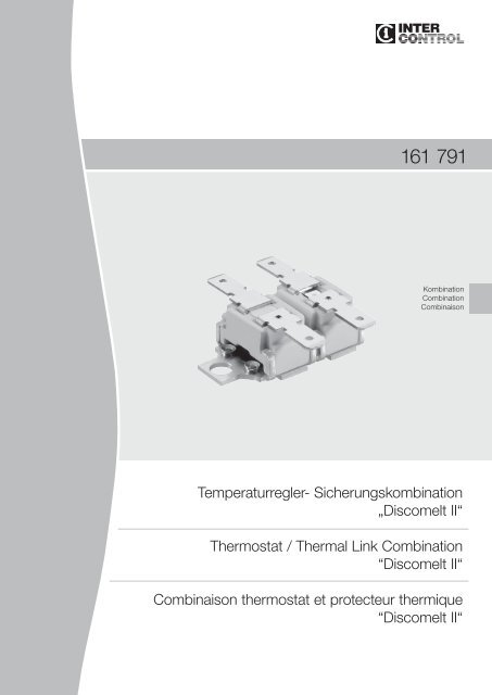
161 791<br />
Kombination<br />
Combination<br />
Combinaison<br />
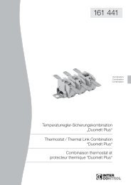
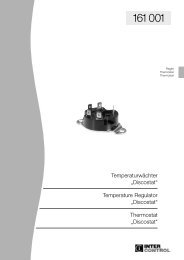
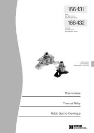
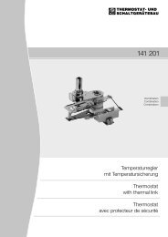
Temperaturregler- Sicherungskombination<br />
„<strong>Discomelt</strong> <strong>II</strong>“<br />
Thermostat / Thermal Link Combination<br />
“<strong>Discomelt</strong> <strong>II</strong>“<br />
Combinaison thermostat et protecteur thermique<br />
“<strong>Discomelt</strong> <strong>II</strong>“
161 791<br />
Anwendung<br />
Die Temperaturregler-Temperatursicherungskombination<br />
Typ 161 791 kann bei sachgemäßer<br />
Anwendung überall dort eingesetzt<br />
werden, wo eine festgelegte Temperatur<br />
geregelt bzw. überwacht werden soll und<br />
zusätzlich eine höchstzulässige Temperatur<br />
nicht überschritten werden darf, z.B. in Hausgeräten,<br />
wie Geschirrspülern und Waschmaschinen,<br />
elektrischen Kleingeräten, wie<br />
Kaffeemaschinen, Dampfgeräten etc. oder in<br />
elektrisch überwachten Warmwassergeräten.<br />
Aufbau und Wirkungsweise<br />
Als Temperaturfühler des Reglers dient eine<br />
gewölbte Bimetallschnappscheibe. Sie liegt<br />
direkt auf der Grundplatte der Kombination und<br />
kann somit schnell auf Temperaturänderungen<br />
reagieren. Bei Erreichen der festgelegten<br />
Abschalttemperatur bewirkt die Bimetallschnappscheibe<br />
das momentartige Öffnen<br />
des elektrischen Stromkreises. Nach der Abkühlphase<br />
schnappt sie in die ursprüngliche<br />
Position zurück, womit der Stromkreis wieder<br />
geschlossen wird. Die Schalttemperatur ist<br />
innerhalb eines breiten Bereiches frei wählbar.<br />
Die Temperatursicherung, geprüft nach DIN<br />
VDE 0821 / EN 60691, besitzt einen Schmelzloteinsatz,<br />
der in direktem Wärmekontakt mit<br />
der Befestigungsfläche steht. Bei Erreichen<br />
der vorbestimmten Ansprechtemperatur<br />
schmilzt das Lot und bewirkt die dauerhafte<br />
Öffnung des Stromkreises. Wiedereinschaltung<br />
ist nicht mehr möglich. 5 verschiedene<br />
Sicherungstemperaturen sind verfügbar.<br />
Die beiden Komponenten Temperaturregler<br />
und Temperatursicherung besitzen eine gemeinsame<br />
Grundplatte, die die Wärmeleitung übernimmt.<br />
Damit ist sichergestellt, dass die thermische<br />
Information für Regler und Sicherung<br />
immer aus exakt der gleichen Quelle stammt.<br />
Vorteile<br />
- 2 Komponenten auf einer Grundplatte<br />
- Geschütztes Kontaktsystem, keine Abdeckkappe<br />
notwendig<br />
- Einfache Montage<br />
- Sicherungstemperatur bis zu 318 °C<br />
- Hohe Dauerbetriebstemperatur T h<br />
- Hohe Qualität durch vollautomatische<br />
Fertigung<br />
- Sehr schnelle Ansprechzeit der Sicherung<br />
durch integriertes Schmelzlot in der Grundplatte<br />
- Hohe Kontaktöffnungskräfte<br />
- Hohe Lebensdauer<br />
Ausführungen<br />
Die verschiedenen Anschluss- und Befestigungsmöglichkeiten<br />
sind auf der Rückseite<br />
dargestellt.<br />
Application<br />
Properly installed, the thermostat / thermal<br />
link combination type 161 791 may be used<br />
for applications where a fixed temperature<br />
needs to be monitored or controlled and a<br />
maximum temperature must not be exceeded,<br />
for example in household appliances such<br />
as dishwashers and washing machines, small<br />
electrical appliances such as coffeemakers,<br />
steam generators etc. or in electrically monitored<br />
water heaters.<br />
Structure and Function<br />
A vaulted bimetal disc is used as a temperature<br />
sensing element in the thermostat.<br />
The disc is placed in direct contact with the<br />
mounting plate of the combination therefore<br />
reacting quickly to changes in temperature.<br />
Upon reaching the preset temperature the<br />
bimetal disc operates and opens the electrical<br />
circuit. Upon cooling, the disc snaps back into<br />
its original position thereby closing the circuit<br />
again. The switching temperature is freely<br />
selectable within a wide range.<br />
The thermal link, approved in accordance<br />
with DIN VDE 0821 / EN 60691, has a solder<br />
insert in the mounting plate which is in direct<br />
thermal contact with the surface that is to be<br />
monitored. When the preset temperature is<br />
reached, the solder melts causing a pin to<br />
move which results in the electrical contacts<br />
opening. Resetting is not possible.<br />
5 different preset solder temperatures are<br />
available.<br />
The two components thermostat and thermal<br />
link have a common mounting plate, which<br />
is responsible for thermal conduction. This<br />
ensures that the thermal information for thermostat<br />
and thermal link always comes from<br />
exactly the same source.<br />
Advantages<br />
- 2 components on one mounting plate<br />
- Covered contacts, no additional protective<br />
cap necessary<br />
- Easy mounting<br />
- Thermal link temperature up to 318 °C<br />
- High holding temperature T h<br />
- Automatic manufacturing ensures high quality<br />
- Very fast response due to solder insert in the<br />
mounting plate<br />
- High force to open contacts<br />
- Long life<br />
Design<br />
The various types of fixing arrangements and<br />
terminals are described on the back page.<br />
Application<br />
Après une étude d‘implantation, la combinaison<br />
thermostat et protecteur thermique type<br />
161 791 peut être utilisé partout où un appareil<br />
nécessite une régulation et une sécurité<br />
thermique, par exemple dans les lave-vaisselles<br />
et lave-linges, petits appareils électriques<br />
comme les cafetières, appareils vapeur etc.<br />
Construction et fonctionnement<br />
Un disque embouti bimétallique sert de sonde<br />
de température. Il se trouve directement sur la<br />
base du thermostat bimétallique et peut ainsi<br />
réagir rapidement aux changements de température.<br />
A la température de coupure souhaitée,<br />
ce disque bimétallique à déclic produit<br />
l’ouverture brusque du circuit électrique.<br />
Après la phase de refroidissement, il reprend<br />
sa postion initiale, refermant ainsi le circuit.<br />
Le protecteur thermique, homologué selon<br />
DIN VDE 0821 / EN 60691 possède une<br />
partie fusible, qui est en contact direct avec la<br />
surface de fixation. A la température assignée<br />
de fonctionnement, le fusible fond et les<br />
contacts s‘ouvrent durablement. Un ré-enclenchement<br />
n‘est plus possible.<br />
5 températures de sécurité différentes sont<br />
disponibles.<br />
Les 2 composants, thermostat et protecteur<br />
thermique possèdent une platine commune,<br />
qui reçoit le courant. Ainsi l’information<br />
thermique pour le thermostat et la sécurité<br />
provient toujours de la même source.<br />
Avantages<br />
- 2 composants sur une même platine<br />
- Contacts protégés, pas de capsule de protection<br />
supplémentaire nécessaire<br />
- Montage simple<br />
- Température de protecteur thermique<br />
jusqu’à 318 °C<br />
- Haute température de maintien T h<br />
- Haut niveau de qualité grâce à une fabrication<br />
automatisée<br />
- Réponse très rapide grâce au point de<br />
fusion placé directement sur la platine<br />
- Grande puissance d’ouverture du contact<br />
- Longue durée de vie<br />
Versions<br />
Les différentes possibilités de connexions et<br />
de fixation figurent au verso.
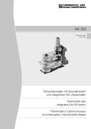
Anlage Typ 155 131, integriert in Typ 161 791<br />
Anwendung<br />
Die Temperatursicherung Typ 155 131 kann<br />
bei sachgemäßer Anwendung überall dort<br />
eingesetzt werden, wo eine höchstzulässige<br />
Temperatur nicht überschritten werden<br />
darf, z.B. in Kaffeemaschinen, Bügeleisen,<br />
Geschirrspülern, Wäschetrocknern bzw. zum<br />
Schutz von elektrischen Heizelementen.<br />
Aufbau und Wirkungsweise<br />
Die Temperatursicherung besitzt einen Schmelzloteinsatz,<br />
der in direktem Wärmekontakt mit<br />
der Befestigungsfläche steht. Bei Erreichen<br />
der vorbestimmten Ansprechtemperatur<br />
schmilzt das Lot und bewirkt die dauerhafte<br />
Öffnung des Stromkreises. Wiedereinschaltung<br />
ist nicht mehr möglich.<br />
Vorteile<br />
- Stromführung bis 15 A<br />
- Geschütztes Kontaktsystem, keine Abdeckkappe<br />
notwendig<br />
- Sehr schnelle Ansprechzeit durch integriertes<br />
Schmelzlot in der Grundplatte<br />
- Einfache Montage<br />
- Hohe Dauerbetriebstemperatur T h<br />
- Hohe Qualität durch vollautomatische<br />
Fertigung<br />
Ausführungen<br />
Die verschiedenen Anschluss- und Befestigungsmöglichkeiten<br />
sind auf der Rückseite<br />
dargestellt.<br />
Einbauhinweis<br />
Beim Einbau der Temperatursicherung müssen<br />
die geltenden elektrischen Anforderungen (z.B.<br />
Kriech- und Luftstrecken) nach der jeweiligen<br />
Bestimmung für das Gerät, z.B. DIN VDE<br />
0700 (IEC 60335-1), sowohl unter üblichen<br />
Bedingungen wie auch im Fehlerfall eingehalten<br />
werden.<br />
Die Anforderungen des Anwendungshinweises<br />
in Anhang A der DIN VDE 0821 EN 60 691<br />
sollten berücksichtigt werden.<br />
Bei der Montage der Temperatursicherung in<br />
einem Gerät ist zu beachten:<br />
- Die elektrischen Anschlüsse sind für innere<br />
Verdrahtung vorgesehen;<br />
- Das elektrische Schaltwerk innerhalb des<br />
Keramikgehäuses darf nicht mit Werkzeugen,<br />
scharfen Gegenständen o.ä. berührt werden,<br />
um mechanische Beschädigungen und damit<br />
Funktionsbeeinträchtigungen zu vermeiden.<br />
Application<br />
Properly installed, the thermal link type 155<br />
131 may be used for applications where a<br />
maximum temperature must not be exceeded,<br />
for example in coffee makers, irons, dishwashers,<br />
dryers and to protect electric heating<br />
elements.<br />
Structure and Function<br />
The thermal link has a melt solder insert in the<br />
mounting plate which is in direct thermal contact<br />
with the surface that is to be monitored.<br />
When the preset temperature is reached, the<br />
solder melts causing a pin to move which<br />
results in the electrical contacts opening.<br />
Resetting is not possible.<br />
Advantages<br />
- Current rating up to 15 A<br />
- Covered contacts, no additional protective<br />
cap necessary<br />
- Very fast response due to melt solder insert<br />
in the mounting plate<br />
- Easy mounting<br />
- High holding temperature T h<br />
- Automatic manufacturing ensures high quality<br />
Design<br />
The various types of fixing arrangements and<br />
terminals are described on the back page.<br />
Mounting requirements<br />
During installation, compliance with all relevant<br />
electrical requirements must be ensured<br />
with special regard to insulation resistance,<br />
dielectric strength, creepage distances and<br />
clearances both under normal conditions and<br />
in case of a fault, as specified in the relevant<br />
equipment standard, for example DIN VDE<br />
0700 (IEC 60335-1).<br />
The requirements in the application note in<br />
extension A of the DIN VDE 0821 EN 60 691<br />
shall be taken into consideration.<br />
When mounting the thermal link the following<br />
requirements shall be observed:<br />
- the terminals shall be used for internal connections<br />
only;<br />
- the switch mechanism inside the ceramic<br />
housing must not be touched by any tools or<br />
similar objects to avoid damage and possible<br />
malfunctions.<br />
Application<br />
Après une étude d‘implantation, le protecteur<br />
thermique type 155 131 peut être utilisé<br />
partout où un appareil nécessite une sécurité<br />
thermique, par exemple les fers à repasser,<br />
les cafetières, les friteuses, etc.<br />
Construction et fonctionnement<br />
Le protecteur thermique possède une partie<br />
fusible, qui est en contact direct avec la surface<br />
de fixation. A la température assignée de<br />
fonctionnement, le fusible fond et les contacts<br />
s‘ouvrent durablement. Un ré-enclenchement<br />
n‘est plus possible.<br />
Avantages<br />
- Ampérage maxi 15 A<br />
- Contacts protégés, pas de capsule de<br />
protection supplémentaire nécessaire<br />
- Réponse très rapide grâce au point de<br />
fusion placé directement sur la platine<br />
- Montage simple<br />
- Haute température de maintien T h<br />
- Haut niveau de qualité grâce à une fabrication<br />
automatisée<br />
Versions<br />
Les différentes possibilités de connexions et<br />
de fixation figurent au verso.<br />
Indications de montage<br />
Lors du montage du protecteur thermique, les<br />
exigences électriques en vigueur doivent être<br />
respectées selon la destination du protecteur,<br />
propre à chaque appareil, par exemple<br />
en fonction de la norme DIN VDE 0700 (IEC<br />
60335-1) aussi bien que dans les conditions<br />
de fonctionnement habituel que dans les cas<br />
de mauvais fonctionnement. Les instructions<br />
de montage figurant annex A de la norme DIN<br />
EN 60 691 doivent être prises en considération.<br />
Lors de l‘installation du protecteur dans<br />
l‘appareil, il vous faudra tenir compte des<br />
points suivants:<br />
- les connexions électriques sont prévues<br />
pour un câblage interne;<br />
- ne pas toucher les pièces de l’ensemble de<br />
commutation, à l’interieur du corps en céramique,<br />
avec un outil, un objet coupant ou tout<br />
autre objet afin d’éviter un endommagement<br />
mécanique et par là-même une détérioration<br />
de la fonction.
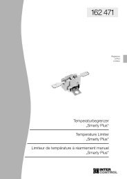
Anlage Typ 155 131, integriert in Typ 161 791<br />
Technische Daten<br />
Die Temperatursicherung „Minimelt <strong>II</strong>“ ist nach<br />
DIN EN 60 691 geprüft und für folgende Bedingungen<br />
geeignet:<br />
Umgebungsbedingungen:<br />
Temperatursicherung zur Verwendung unter<br />
üblichen atmosphärischen Bedingungen.<br />
Stromkreisbedingungen:<br />
Temperatursicherung zur Verwendung in<br />
ohmschen Stromkreisen.<br />
Kriechstromfestigkeit:<br />
PTI > 250<br />
Charakteristische<br />
Ströme<br />
VDE/*) cURus<br />
Bemessungsstrom Ir 15 A<br />
Abschaltstrom Ib 22,5 A<br />
Kurzzeitüberlaststrom Ip 225 A<br />
Bemessungsspannung Ur 230 V<br />
Erläuterungen zum Typ-Schlüssel<br />
Die komplette Typnummer wird werkseitig<br />
bei Festlegung der konstruktiven Ausführung<br />
zusammen mit einer Zeichnung erstellt.<br />
Typ-Schlüssel: z. B.<br />
155 131.301 01 7 B<br />
1 2 3 4 5<br />
1 Typ (identifiziert Bauform)<br />
2 Ausführungsvarianten-Nr. (identifiziert<br />
Abmessungen, Anschlüsse, Befestigungsart)<br />
3 Fertigungsdatum - Woche<br />
4 Fertigungsdatum - Jahr<br />
5 Code für Fertigungsstätte<br />
Besondere Hinweise<br />
Die Temperatursicherung ist nicht geeignet<br />
zum Vergießen oder zur Verwendung in<br />
imprägnierten Wicklungen.<br />
Diese Temperatursicherung ist ein nicht reparierbares<br />
Bauteil. Im Falle des Austausches<br />
darf nur eine gleiche Temperatursicherung mit<br />
der mit der baugleichen Typennummer und<br />
Bemessungsschalttemperatur T f<br />
verwendet<br />
werden, die in der genau gleichen Weise<br />
eingebaut werden muss.<br />
T h<br />
gilt nicht für die Umgebungstemperatur,<br />
sondern für die unter den Einbaubedingungen<br />
an der Grundplatte ermittelte Temperatur<br />
nahe des Schmelzloteinsatzes.<br />
Nach UL/EN 60 691(10.6 ist im Fehlerfall<br />
der Temperaturbereich von T h<br />
bis T f<br />
+5K<br />
mit > 1 K/min zu durchfahren.<br />
*) cURus = UL / CSA<br />
Technical Data<br />
The thermal link „Minimelt <strong>II</strong>“ is approved according<br />
to DIN EN 60 691 and is suitable for<br />
the following conditions:<br />
Ambient conditions:<br />
The thermal link is intended for use in normal<br />
atmospheric conditions.<br />
Circuit conditions:<br />
The thermal link is intended for use in resistive<br />
circuits only.<br />
Proof tracking index:<br />
PTI > 250<br />
Characteristic<br />
Currents<br />
VDE/*) cURus<br />
Rated current Ir 15 A<br />
Interrupting current Ib 22,5 A<br />
Transient overload<br />
current Ip 225 A<br />
Rated Voltage Ur 230 V<br />
Note concerning type number<br />
The complete number will be issued by the<br />
manufacturer together with a drawing based<br />
on the specific design.<br />
Type designation code: e.g.<br />
155 131.301 01 7 B<br />
1 2 3 4 5<br />
1 Type (identifies design)<br />
2 Variants suffix (identifies dimensions,<br />
terminals, fixing arrangements)<br />
3 Date of production – week<br />
4 Date of production – year<br />
5 Code for manufacturing plant<br />
Special instructions<br />
The thermal link should neither be coated or<br />
potted nor be used in impregnated windings.<br />
The thermal link is a non repairable part. In<br />
case of replacement an equivalent thermal<br />
link with the same type number and rated<br />
functional temperature T f<br />
should be used,<br />
mounted in exactly the same way.<br />
T h<br />
does not relate to the ambient temperature<br />
only but to the temperature measured at the<br />
mounting plate close to the thermal element.<br />
According to UL/EN 60 691/10.6 in the case<br />
of a fault, a rate of temperature change of<br />
> 1K per minute is required between T h<br />
and T f<br />
+5K to trip the thermal link.<br />
*) cURus = UL / CSA<br />
Caractéristiques<br />
Le protecteur thermique es conforme à la<br />
norme DIN EN 60 691 et est adapté aux<br />
conditions suivantes:<br />
Conditions ambiantes:<br />
Conditions atmosphériques habituelles<br />
Conditions électriques:<br />
Circuit ohmique<br />
Densité électrique:<br />
PTI > 250<br />
Courants électriques<br />
caractéristiques VDE/*) cURus<br />
Courant de mesure Ir 15 A<br />
Courant de coupure Ib 22,5 A<br />
Courant de surcharge<br />
ponctuelle Ip 225 A<br />
Tension de mesure Ur 230 V<br />
Codification définitive<br />
La référence complète est établie en même<br />
temps qu’un plan.<br />
Codification: Par exemple<br />
155 131.301 01 7 B<br />
1 2 3 4 5<br />
1 Type (identifie la série)<br />
2 Numéro en fonction des variantes de la version<br />
souhaitée (identifie les dimensions, les<br />
connexions, le mode de fixation)<br />
3 Semaine de fabrication<br />
4 Année de fabrication<br />
5 Code identifiant le lieu de fabrication<br />
Remarques<br />
Le protecteur thermique ne doit pas être<br />
utilisé dans des enrouleurs imprégnés.<br />
Celui-ci est un composant non réparable.<br />
En cas d‘échange, seul le même protecteur,<br />
de même référence , avec la même température<br />
assignée de fonctionnement T f<br />
pourra<br />
être utilisé et monté exactement de la même<br />
façon. T h<br />
ne tient pas compte de la température<br />
ambiante mais de la température relevée<br />
dans les conditions d‘utilisation à la plaque<br />
près de la partie fusible.<br />
En cas de défaut, selon UL/EN 60 691/10.6,<br />
la variation de température dans la plage comprise<br />
entre T h<br />
et T f<br />
+5K, doit être > à 1 K/min.<br />
*) cURus = UL / CSA<br />
Charakteristische Temperaturen / Characteristic Temperature /<br />
Températures caractéristiques<br />
T f<br />
... Bemessungstemperatur / Rated functioning temperature / Température assignee<br />
de fonctionnement<br />
T h<br />
... Dauerbetriebstemperatur gemäß / Holding temperature according to / Température<br />
de maintien, conform à la norme DIN EN 60691 / UL 60691 / (gemessen an der<br />
Grundplatte nahe des Schmelzloteinsatzes) / (measured at mounting plate close to<br />
the thermal element) / (mesurée à la base de la sécurité thermique près de la partie<br />
fusible)<br />
T m<br />
... Max. Grenztemperatur / Maximum temperature limit / Température limite maximale<br />
T f<br />
-10 K T h<br />
T m<br />
206 °C 170 °C 500 °C<br />
229 °C 205 °C 500 °C<br />
260 °C 230 °C 500 °C<br />
298 °C 260 °C 500 °C<br />
318 °C 280 °C 500 °C<br />
Toleranz für T f<br />
ist nach VDE 0821 / EN 60691 - 10 °C<br />
Tolerance for T f<br />
acc. to VDE 0821 / EN 60691 - 10 °C<br />
Tolérance pour T f<br />
selon VDE 0821 / EN 60691 - 10 °C
161 791<br />
Technische Daten<br />
Bemessungsspannung / Bemessungsstrom:<br />
AC 10 A, 230 V oder 13,5 A, 120 V<br />
ohmische Last, 100.000 Schaltungen<br />
Maximaltemperatur:<br />
T 200 °C (T 250 °C auf Anfrage)<br />
Bemessungsschalttemperatur:<br />
50 – 200 °C (bis zu 250 °C auf Anfrage)<br />
Abschalttoleranz:<br />
± 5 K<br />
Schaltdifferenz:<br />
< 25 K<br />
Temperaturänderungsgeschwindigkeit: > 1 K/min<br />
Aufbau:<br />
nach DIN EN 60730 Schutzklasse I<br />
Kriechstromfestigkeit: PTI 175<br />
Prüfzeichen:<br />
siehe Approbationsliste, die Ihnen auf Anforderung gerne zur<br />
Verfügung gestellt wird.<br />
Technische Details der Temperatursicherung:<br />
siehe Anlage<br />
Technical Data<br />
Nominal voltage / current:<br />
AC 10 A, 230 V or 13.5 A, 120 V<br />
non-inductive load, 100,000 cycles<br />
Maximum temperature:<br />
T 200 °C (T 250 °C on request)<br />
Nominal switching temperature:<br />
50 – 200 °C (up to 250 °C on request)<br />
Switch-off tolerance:<br />
± 5 K<br />
Differential:<br />
< 25 K<br />
Rate of temperature rise:<br />
> 1 K/min<br />
Design:<br />
according to DIN EN 60730 protection class I<br />
Proof tracking index: PTI 175<br />
Mark of conformity:<br />
refer to approvals list which is available on request<br />
Technical details for thermal link:<br />
see enclosure<br />
Caractéristiques Tension de mesure / courant nominal: AC 10 A, 230 V ou 13,5 A, 120 V<br />
circuit ohmique, 100.000 cycles<br />
Température maximale d’emploi:<br />
T 200 °C (T 250 °C sur demande)<br />
Température de coupure nominal:<br />
50 – 200 °C (jusqu’ à 250 °C sur demande)<br />
Tolérance de coupure:<br />
± 5 K<br />
Différentiel:<br />
< 25 K<br />
Vitesse de variation de température:<br />
> 1 K/min<br />
Construction:<br />
après DIN EN 60730, sécurité classe I<br />
Indice de résistance au cheminement: PTI 175<br />
Marque de conformité:<br />
voir la liste des homologations (disponible sur demande)<br />
Spécifications techniques<br />
du protecteur thermique:<br />
voir annexe<br />
Die von uns genannten technischen Daten wurden von uns unter Laborbedingungen<br />
nach allgemein gültigen Prüfvorschriften, insbesondere<br />
DIN EN-Vorschriften, ermittelt. Nur insoweit werden Eigenschaften zugesichert.<br />
Die Prüfung der Eignung für den vom Auftraggeber vorgesehenen<br />
Verwendungszweck bzw. den Einsatz unter Gebrauchsbedingungen<br />
obliegt dem Auftraggeber; hierfür übernehmen wir keine<br />
Gewährleistung. Änderungen vorbehalten.<br />
All technical data has been determined under laboratory conditions in<br />
accordance with the relevant test regulations, in particular DIN EN<br />
Standards. The data is guaranteed in this respect only. It is the responsibility<br />
of the customer to ensure suitability for the proposed application<br />
or for operation according to conditions of use. We can offer no warranty<br />
in this respect. Subject to change without notice.<br />
Les données techniques que nous indiquons ont été déterminées dans<br />
les conditions de laboratoire et suivant les prescriptions valables en général,<br />
notamment les normes DIN EN. Les propriétés garanties ne le<br />
sont que dans ce cadre. C‘est au client d‘examiner si ces instruments<br />
conviennent à son utilisation prévue ou à l‘application selon les conditions<br />
de leur mise en œuvre: En ce qui concerne ce point, nous n‘assumons<br />
aucune garantie. Sous reserve de modification.
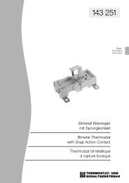
161 791<br />
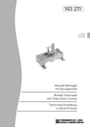
Abmessungen<br />
Dimensions<br />
Dimensions<br />
34<br />
26,75<br />
12,3<br />
Sockelabstand<br />
1,2<br />
0,8 ±0,03<br />
TR1<br />
34,3 ±0,5<br />
19 ±0,2<br />
8<br />
4,3 +0.1<br />
10,2 +0.3<br />
6,3 -0.1<br />
23,6 ±0,5<br />
40<br />
28,3<br />
Anschlussstellung<br />
Terminal position<br />
Position de la connexion<br />
90° -5°<br />
16,6 ±0,2<br />
horizontal 90 o -10 o Autres angles sur demande<br />
Andere Abwinkelungen auf Anfrage<br />
Other angles upon request<br />
Befestigungen<br />
Mounting<br />
Fixation<br />
8<br />
Bohrung wahlweise:<br />
3,2 +0,1<br />
3,7 +0,1<br />
4,3 +0,1<br />
8<br />
Bohrung wahlweise:<br />
3,2 +0,1<br />
3,7 +0,1<br />
4,3 +0,1<br />
8<br />
Bohrung wahlweise:<br />
3,2 +0,1<br />
3,7 +0,1<br />
4,3 +0,1<br />
34<br />
31<br />
26,75<br />
40<br />
34<br />
40<br />
34<br />
28,8<br />
0,8 ±0,03<br />
1 -0,05<br />
28,3<br />
12,3<br />
6 - 9,5<br />
1,2<br />
Drehmoment für<br />
Befestigung max. 1,2Nm<br />
Sockelabstand<br />
TR 1<br />
45°<br />
34,3 ±0,5<br />
3<br />
M4<br />
19 ±0,2<br />
0,8<br />
6,3 ±0,3<br />
7,4 ±0,3 10,2 +0,3<br />
Gewinde bis<br />
max. 0,8 gängig<br />
6,3 -0,1<br />
23,6 ±0,5<br />
8 ±0,2<br />
TS2<br />
TS 2<br />
Anschlüsse<br />
Terminals<br />
Connexion<br />
6,3 -0,1 4,8 -0,1 6,3 -0,1<br />
6,3 -0,1<br />
Steckanschlüsse<br />
Push-on terminals<br />
Cosses à enficher<br />
Steckanschlüsse<br />
Push-on terminals<br />
Cosses à enficher<br />
Schweißanschlüsse, lang<br />
Welding teminals, long<br />
Cosses à souder, longues<br />
Schweißanschlüsse kurz<br />
Welding teminals, short<br />
Cosses à souder, courtes<br />
6,3<br />
6,3<br />
6,3<br />
Schweißanchlüsse lang mit Längsrippen<br />
Long terminals with welding ribs lengthwise<br />
Cosses longues à sertir<br />
Schweißanschlüsse kurz mit Längsrippen<br />
Short terminals with welding ribs lengthwise<br />
Cosses courtes à sertir<br />
Schweißanschlüsse mit Querrippen<br />
Terminals with welding ribs crosswise<br />
Cosses à sertir perpendiculairement<br />
M4<br />
Hausadresse:<br />
Postfachadresse:<br />
Inter Control<br />
Hermann Köhler Elektrik GmbH & Co. KG<br />
Schafhofstraße 30<br />
90411 Nürnberg, Germany<br />
Postfach 13 01 63<br />
90113 Nürnberg, Germany<br />
Fon (09 11) 95 22-5<br />
Fax (09 11) 95 22-875<br />
Internet www.intercontrol.de<br />
Printed in Germany 0309 A2, ICVT, 11