Trautmann Gmbh & Co. KG - Calira
Trautmann Gmbh & Co. KG - Calira
Trautmann Gmbh & Co. KG - Calira

Create successful ePaper yourself
Turn your PDF publications into a flip-book with our unique Google optimized e-Paper software.
Betriebsanleitung<br />
Operating Instructions<br />
Mode d´emploi<br />
Bruksanvisning<br />
Modular-Electric-System<br />
Module C3<br />
Lerchenfeldstr. 9 87600 Kaufbeuren Tel.: +49 (0)8341 9764-0 Fax: +49 (0)8341 67806
Inhaltsverzeichnis<br />
! " # ! $<br />
Sicherheitshinweise........................................................ 3<br />
Verwendungszweck ....................................................... 3<br />
Beschreibung ................................................................. 4<br />
Hauptschalter ........................................................... 4<br />
Ladekontrollanzeige................................................. 5<br />
Batteriespannungsanzeige ........................................ 5<br />
Technische Daten........................................................... 6<br />
Montage......................................................................... 6<br />
Anschluss....................................................................... 7<br />
Inbetriebnahme .............................................................. 8<br />
Maßnahmen bei Störungen ............................................ 8<br />
Instandsetzung ............................................................... 9<br />
Garantie ......................................................................... 9<br />
Stand: 30.06.2005<br />
Technische Änderungen vorbehalten<br />
2<br />
Lerchenfeldstr. 9 87600 Kaufbeuren Tel.: +49 (0)8341 9764-0 Fax: +49 (0)8341 67806
! " # ! $<br />
Allgemeine Sicherheitshinweise aufmerksam lesen!<br />
Achtung!<br />
Beim Gebrauch von elektrischen Geräten sind zum Schutz vor elektrischem<br />
Schlag, Verletzung und Brandgefahr folgende grundsätzliche Sicherheitsmaßnahmen<br />
zu beachten. Lesen und beachten Sie diese Hinweise, bevor Sie das<br />
Gerät benutzen.<br />
Aufstellen<br />
Achten Sie darauf, dass die Geräte sicher aufgestellt werden und nicht<br />
herabfallen oder umstürzen können. Legen Sie Leitungen stets so, dass keine<br />
Stolpergefahr entsteht. Setzen Sie Elektrogeräte nicht dem Regen aus.<br />
Betreiben Sie Elektrogeräte nicht in feuchter oder nasser Umgebung. Betreiben<br />
Sie Elektrogeräte nicht in der Nähe von brennbaren Flüssigkeiten oder Gasen.<br />
Stellen Sie Ihre elektrischen Geräte so auf, dass Kinder keinen Zugriff darauf<br />
haben.<br />
Schutz vor elektrischem Schlag<br />
Betreiben Sie nur Geräte deren Gehäuse und Leitungen unbeschädigt sind.<br />
Achten Sie auf sichere Verlegung der Kabel. Ziehen Sie nicht an den Kabeln.<br />
Achtung!<br />
Den elektrischen Anschluss der Geräte über einen Fehlerstromschutzschalter<br />
30 mA Nennfehlerstrom absichern und nur so betreiben. EVU-Vorschriften<br />
beachten.<br />
Gebrauch<br />
Benutzen Sie keine elektrischen Geräte entgegen dem, vom Hersteller<br />
angegebenen Verwendungszweck.<br />
Zubehör<br />
Benutzen Sie nur Zubehörteile und Zusatzgeräte die vom Hersteller geliefert<br />
oder empfohlen werden. Der Einsatz anderer Zubehöre birgt Gefahren.<br />
Verwendungszweck<br />
Das Modular-Electric-System Module C3 kann nicht als Einzelgerät, sondern<br />
nur zusammen mit einem Modular-Electric-System Module A und Module B<br />
betrieben werden. Das Module C3 dient zur Erweiterung der anderen Module<br />
als Kontrolltafel. Das Module C3 ist zusammen mit dem MES Module A und<br />
Module B für den Einsatz im Caravan konstruiert. Die Module dürfen nur in<br />
trockenen Räumen betrieben werden.<br />
3<br />
Lerchenfeldstr. 9 87600 Kaufbeuren Tel.: +49 (0)8341 9764-0 Fax: +49 (0)8341 67806
Beschreibung<br />
! " # ! $<br />
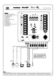
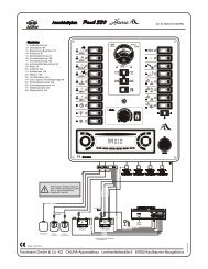
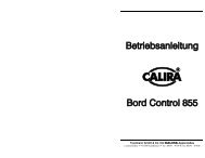
Die Kontrolltafel Module C3 dient zur Anzeige des Ladezustandes (Pos. 2 und<br />
3) der Versorgungsbatterie (Batterie II), zur Ladekontrollanzeige bei<br />
Netzbetrieb (Pos. 4) und als Hauptschalter (Pos. 1).<br />
Hauptschalter<br />
Durch betätigen des Hauptschalters (beleuchteter Taster Bild 1 Pos. 1) wird<br />
das Hauptschalterrelais im Module B aktiviert. Der Hauptschalter leuchtet im<br />
eingeschalteten Zustand grün. Mit dem Hauptschalter können die 12 Volt<br />
Verbraucher, in Verbindung mit dem Hauptschalterrelais, EIN (Taster leuchtet<br />
grün) und durch erneutes betätigen AUS geschaltet werden.<br />
Sinkt die Spannung der Versorgungsbatterie unter 10,8 Volt so schaltet das<br />
Hauptschalterrelais automatisch aus. Steigt die Spannung der<br />
Versorgungsbatterie wieder über 12,5 Volt an, so schaltet das<br />
Hauptschalterrelais ein. Zwischen einer Batteriespannung von 10,8 Volt und<br />
4<br />
Lerchenfeldstr. 9 87600 Kaufbeuren Tel.: +49 (0)8341 9764-0 Fax: +49 (0)8341 67806<br />
1<br />
4<br />
3<br />
2
! " # ! $<br />
12,5 Volt kann das Hauptschalterrelais kurzzeitig (ca. 3 Minuten) durch<br />
drücken des Taster aktiviert werden (Noteinfunktion).<br />
Ladekontrollanzeige<br />
Die Ladekontrollanzeige (grün, Bild 1 Pos. 4) leuchtet, unabhängig vom<br />
Hauptschalter, wenn das Module B im Netzladebetrieb ist und die<br />
Versorgungsbatterie geladen wird. Ladevorgang siehe Beschreibung Module<br />
B.<br />
Batteriespannungsanzeige<br />
Durch drücken des Tasters (Bild 1 Pos. 2) wird die Spannung der<br />
Versorgungsbatterie in der Batteriespannungsanzeige (Bild 1 Pos. 3) über eine<br />
LED-Kette dargestellt.<br />
Grüner Bereich ausreichende Batteriespannung<br />
Gelber Bereich kritische Batteriespannung<br />
Roter Bereich zu niedrige Batteriespannung<br />
Die Anzeige der Batteriespannung ist nur mit eingeschaltetem Hauptschalter<br />
möglich.<br />
5<br />
Lerchenfeldstr. 9 87600 Kaufbeuren Tel.: +49 (0)8341 9764-0 Fax: +49 (0)8341 67806
Technische Daten<br />
Stromversorgung: Gleichspannung 12 V<br />
! " # ! $<br />
Ausführung: gemäss den Bestimmungen des VDE und des<br />
Gerätesicherheitsgesetzes<br />
Prüfzeichen:<br />
Verwendung: Zur Verwendung im Caravan in Verbindung mit MES<br />
Module A und B<br />
Frontplatte: Aluminium, natur eloxiert, bedruckt<br />
Höhe: 93 mm Breite: 88 mm Gewicht: 70 g (0,7 N)<br />
Montage<br />
Den im Umkarton befindlichen Beipack (Zubehör) entnehmen und auf<br />
Vollständigkeit prüfen.<br />
2 Befestigungsschrauben<br />
1 Serielles RS485 Datenübertragungskabel (4-polig)<br />
1 Betriebsanleitung<br />
Bringen Sie die Kontrolltafel an einer vor Feuchtigkeit geschützten Stelle im<br />
Caravan an. Der Durchbruch für den Einbau der Kontrolltafel muss eine Breite<br />
von ca. 68 mm und eine Höhe von ca. 60 mm aufweisen.<br />
6<br />
Lerchenfeldstr. 9 87600 Kaufbeuren Tel.: +49 (0)8341 9764-0 Fax: +49 (0)8341 67806
Anschluss<br />
Anschluss an Module B<br />
! " # ! $<br />
Stellen Sie sicher, dass alle Versorgungsleitungen von Batterie und Netz der<br />
Module A und B abgeschaltet bzw. getrennt sind. Siehe Betriebsanleitungen<br />
der Module A und B.<br />
Nehmen Sie die Klemmraumabdeckung des Module B ab. Siehe<br />
Betriebsanleitung Module B.<br />
Schließen Sie die 4-poligen Stecker der seriellen RS 485<br />
Datenübertragungsleitung an den Anschluss des Module B an. Siehe<br />
Betriebsanleitung Module B Anschlussplan (Bild 3 Pos. 6).<br />
Schließen Sie die serielle Datenleitung RS485 an den 4-poligen Anschluss am<br />
Module C3 an. Auf dem Module C3 ist ein Hauptschalter integriert. Sollte<br />
bereits ein separater Hauptschalter am Module B angeschlossen sein, wird<br />
dieser durch den Anschluss eines Module C3 funktionslos und kann entfernt<br />
werden.<br />
Abschließende Arbeiten<br />
Prüfen Sie alle Leitungen auf festen Sitz. Bringen Sie die<br />
Klemmraumabdeckung an. Stellen Sie als letztes die Netzverbindung her.<br />
7<br />
Lerchenfeldstr. 9 87600 Kaufbeuren Tel.: +49 (0)8341 9764-0 Fax: +49 (0)8341 67806
Inbetriebnahme<br />
! " # ! $<br />
Das Module C3 ist in Betrieb sobald die Anschlüsse hergestellt sind und der<br />
Hauptschalter betätigt ist.<br />
Maßnahmen bei Störungen<br />
Störung Maßnahme<br />
Die Spannungsanzeige<br />
zeigt nicht<br />
an.<br />
Die Ladekontrollanzeige<br />
zeigt nicht<br />
an.<br />
Der Hauptschalter<br />
reagiert nicht.<br />
Sie können keine<br />
der hier beschriebenen<br />
Störungen<br />
feststellen. Das<br />
Gerät arbeitet<br />
dennoch nicht.<br />
Betätigen Sie den Hauptschalter. Prüfen Sie den<br />
Anschluss und die Leitung zum Module B.<br />
Prüfen Sie den Anschluss und die Leitung für Module B.<br />
Prüfen Sie den Anschluss und die Leitung zum Module B<br />
sowie die Sicherungen und Anschlüsse der Module A und<br />
B. Siehe auch Betriebsanleitung Module B.<br />
Wenden Sie sich direkt an den Hersteller:<br />
<strong>Trautmann</strong> GmbH & <strong>Co</strong>. <strong>KG</strong><br />
CALIRA-Apparatebau<br />
Lerchenfeldstr. 9<br />
87600 Kaufbeuren<br />
Servicetelefon: 0190 / 77 03 80<br />
Homepage:<br />
E-Mail: info@calira.de<br />
(1,24 /min)<br />
8<br />
Lerchenfeldstr. 9 87600 Kaufbeuren Tel.: +49 (0)8341 9764-0 Fax: +49 (0)8341 67806
Instandsetzung<br />
! " # ! $<br />
!<br />
Ein defektes Gerät kann nur durch den Hersteller oder dessen Service instand<br />
gesetzt werden. Beachten Sie hier die allgemeinen Sicherheitsbestimmungen.<br />
Garantie<br />
Garantie wird in dem Zeitraum von zwei Jahren ab Kaufdatum gewährt.<br />
Mängel infolge Material- oder Fertigungsfehler werden kostenlos beseitigt<br />
wenn:<br />
Das Gerät dem Hersteller kostenfrei zugesandt wird.<br />
Der Kaufbeleg beiliegt<br />
Das Gerät bestimmungsgemäß behandelt und verwendet wurde.<br />
Keine fremden Ersatzteile eingebaut oder Eingriffe vorgenommen wurden.<br />
Nicht unter die Garantie fallen Folgekosten und natürliche Abnützung.<br />
Wichtig<br />
Bei Geltendmachung von Ansprüchen aus Garantie und Gewährleistung ist<br />
eine ausführliche Beschreibung des Mangels unerlässlich. Detaillierte Hinweise<br />
erleichtern und beschleunigen die Bearbeitung. Bitte haben Sie Verständnis<br />
dafür, dass wir Sendungen, die uns unfrei zugehen, nicht annehmen können.<br />
9<br />
Lerchenfeldstr. 9 87600 Kaufbeuren Tel.: +49 (0)8341 9764-0 Fax: +49 (0)8341 67806
Table of contents<br />
$<br />
%<br />
! " # ! $<br />
" #<br />
Safety instructions........................................................ 11<br />
Purpose ........................................................................ 11<br />
Description................................................................... 12<br />
Main switch............................................................ 12<br />
Charging control display ........................................ 13<br />
Battery voltage display........................................... 13<br />
Technical data.............................................................. 14<br />
Assembly ..................................................................... 14<br />
<strong>Co</strong>nnection................................................................... 15<br />
<strong>Co</strong>mmissioning ............................................................ 16<br />
Procedures in the event of faults.................................. 16<br />
Repairs......................................................................... 17<br />
Warranty ...................................................................... 17<br />
Version: 30.06.2005<br />
The right to make technical modifications is reserved.<br />
10<br />
Lerchenfeldstr. 9 87600 Kaufbeuren Tel.: +49 (0)8341 9764-0 Fax: +49 (0)8341 67806
%<br />
! " # ! $<br />
Please read general safety information carefully!<br />
Attention!<br />
The following important safety instructions must be observed when using<br />
electric devices, as protection against electric shock, injury and fire hazard.<br />
Please read and follow these instructions before using the device.<br />
Setting up<br />
Please ensure that the device is placed securely and cannot fall down or tip<br />
over. Always position cables so that nobody can trip over them. Do not expose<br />
electric devices to rain. Do not operate electric devices in a damp or humid<br />
environment. Do not operate electric devices in the vicinity of flammable<br />
liquids or gases. Place electric devices so that children do not have access to<br />
them.<br />
Protection against electric shock<br />
Only operate devices whose housing and cables are undamaged. Ensure safe<br />
cable positioning. Do not pull cables.<br />
Attention!<br />
Safeguard the electric connection of the devices with a 30 mA-rated leakage<br />
current circuit breaker, and only operate it with this protection. Observe the<br />
power supply companies regulations.<br />
Use<br />
Do not use electric devices other than for the purpose specified by the<br />
manufacturer.<br />
Accessories<br />
Only use accessories and supplementary devices supplied or recommended by<br />
the manufacturer. Using other accessories is hazardous.<br />
Purpose<br />
The Modular-Electric-System Module C3 can not be operated as an individual<br />
unit but only together with Modular-Electric-System Module A and Module B.<br />
The Module C3 serves as control panel for the extension of the other Modules.<br />
The Module C3 is constructed together with the MES Module A and Module B<br />
for deployment in the caravan. The Modules must only be operated in dry<br />
spaces.<br />
11<br />
Lerchenfeldstr. 9 87600 Kaufbeuren Tel.: +49 (0)8341 9764-0 Fax: +49 (0)8341 67806
Description<br />
%<br />
! " # ! $<br />
The Module C3 control panel serves as display of charging condition (pos. 2<br />
and 3) of supply battery (battery II), for charging control indicator during<br />
mains operation (pos. 4) and as main switch (pos. 1).<br />
Main switch<br />
The main switch relay in Module B is activated by operating the main switch<br />
(illuminated button fig. 1 pos. 1). The main switch shines green when switched<br />
on. The 12 volts consumer can be switched to ON (button shines green) using<br />
the main switch and with a further actuation switched OFF, in connection with<br />
the main switch relay.<br />
If the voltage of the supply battery drops below 10.8 volts, the main switch<br />
relay switches off automatically. If the voltage of the supply battery rises again<br />
over 12.5 volts, the main switch relay switches on automatically. Between a<br />
battery voltage of 10.8 volts and 12.5 volts the main switch relay can be briefly<br />
12<br />
Lerchenfeldstr. 9 87600 Kaufbeuren Tel.: +49 (0)8341 9764-0 Fax: +49 (0)8341 67806<br />
1<br />
4<br />
3<br />
2
%<br />
! " # ! $<br />
(approx. 3 minutes) activated by pressing the button (emergency start<br />
function).<br />
Charging control display<br />
The charging control display lights up (green, fig. 1 pos 4) independently of the<br />
main switch, if the Module B is in mains charging operation and the supply<br />
battery is charged. Charging process see Module B description.<br />
Battery voltage display<br />
By pressing the button (fig. 1 pos. 2) the supply battery voltage on the battery<br />
voltage display (fig. 1 pos. 3) is shown by means of a LED chain.<br />
Green area sufficient battery voltage<br />
Yellow area critical battery voltage<br />
Red area battery voltage too low<br />
The display of the battery voltage is only possible with switched on main<br />
switch.<br />
13<br />
Lerchenfeldstr. 9 87600 Kaufbeuren Tel.: +49 (0)8341 9764-0 Fax: +49 (0)8341 67806
Technical data<br />
Power supply: Direct current 12 V<br />
%<br />
! " # ! $<br />
Implementation: According to Association of German Electrotechnical<br />
Engineers regulations and the provisions of the<br />
Instrument Safety Act.<br />
Test labelling:<br />
Use: For use in caravan in connection with MES Module A<br />
and B<br />
Front plate: Aluminium plain anodised / printed<br />
Height: 93 mm Width: 88 mm Weight: 70 g (0.7 N)<br />
Assembly<br />
Remove the items packed separately (accessories) from the main carton, and<br />
check them for completeness.<br />
2 Fastening screws<br />
1 Serial RS485 data transmission cable (4-pole)<br />
1 Operating instructions<br />
Put the control panel onto a part of the caravan that is protected from moisture.<br />
The opening for installing the control panel must be of a breadth of approx. 69<br />
mm and a height of approx. 60 mm.<br />
14<br />
Lerchenfeldstr. 9 87600 Kaufbeuren Tel.: +49 (0)8341 9764-0 Fax: +49 (0)8341 67806
<strong>Co</strong>nnection<br />
%<br />
! " # ! $<br />
% # & $ " $<br />
$ "<br />
<strong>Co</strong>nnection on Module B<br />
Make sure that all power cables from battery and mains of Module A and B are<br />
switched off or separated. See operating instructions of Module A and B.<br />
Remove the terminal area covers from Module B. See operating instruction for<br />
Module B.<br />
<strong>Co</strong>nnect the 4-pole plug of the serial RS 485 data transmission cable to the<br />
connection of Module B. See operating instruction for Module B connection<br />
diagram (fig. 3 pos. 6).<br />
<strong>Co</strong>nnect the serial data cable RS485 to the 4-pole connection on Module C3. A<br />
main switch is integrated onto Module C3. Should there be a separate main<br />
switch already connected on Module B, this will be functionless through the<br />
connection of a Module C3 and can be removed.<br />
<strong>Co</strong>ncluding tasks<br />
Check that all the cables are firm and secure. Put on the terminal area cover.<br />
<strong>Co</strong>nnect the mains as the final step.<br />
15<br />
Lerchenfeldstr. 9 87600 Kaufbeuren Tel.: +49 (0)8341 9764-0 Fax: +49 (0)8341 67806
<strong>Co</strong>mmissioning<br />
%<br />
! " # ! $<br />
The Module C3 is in operation as soon as connections are made and the main<br />
switch is actuated.<br />
Procedures in the event of faults<br />
Fault Action<br />
The voltage<br />
display is not<br />
functioning.<br />
The charging<br />
control display is<br />
not functioning.<br />
The main switch is<br />
not reacting.<br />
None of the faults<br />
described here<br />
seems to apply.<br />
But the device still<br />
does not work.<br />
Actuate the main switch. Check the connection and cable<br />
to Module B.<br />
Check the connection and cable for Module B.<br />
Check the connection and the cable to Module B as well<br />
as the fuse and connections to Module A and B. See also<br />
operating instructions for Module B.<br />
Please contact the manufacturer:<br />
<strong>Trautmann</strong> GmbH & <strong>Co</strong>. <strong>KG</strong><br />
CALIRA-Apparatebau<br />
Lerchenfeldstr. 9<br />
D-87600 Kaufbeuren<br />
Internet: www.calira.de<br />
e-mail: info@calira.de<br />
16<br />
Lerchenfeldstr. 9 87600 Kaufbeuren Tel.: +49 (0)8341 9764-0 Fax: +49 (0)8341 67806
Repairs<br />
%<br />
! " # ! $<br />
% ! " #<br />
$<br />
A faulty device can only be repaired by the manufacturer or by its service<br />
personnel. Please note the relevant general safety regulations.<br />
Warranty<br />
The warranty is in force for a period of two years from date of purchase.<br />
Defects arising from material or manufacturing faults will be rectified free of<br />
charge, provided that:<br />
The device is sent to the manufacturer postage paid.<br />
Proof of purchase is enclosed.<br />
The device has been handled and used according to its specified purpose.<br />
No foreign spare parts were installed and the device has not been<br />
interfered with.<br />
<strong>Co</strong>nsequential costs and normal wear and tear are excluded.<br />
Important<br />
Claims made under warranty should be accompanied by a detailed description<br />
of the fault. This facilitates and expedites the processing. Please bear in mind<br />
that we cannot accept items sent without the correct postage having been paid.<br />
17<br />
Lerchenfeldstr. 9 87600 Kaufbeuren Tel.: +49 (0)8341 9764-0 Fax: +49 (0)8341 67806
Table des matières<br />
! !&<br />
# ' ( ) ! ! $<br />
#) ' #<br />
' ## (<br />
<strong>Co</strong>nsignes de sécurité................................................... 19<br />
Usage prévu ................................................................. 20<br />
Description................................................................... 20<br />
<strong>Co</strong>mmutateur principal........................................... 21<br />
Voyant de contrôle de charge................................. 21<br />
Voyant de tension de batterie................................. 21<br />
Caractéristiques techniques.......................................... 22<br />
Montage....................................................................... 22<br />
Raccordement .............................................................. 23<br />
Mise en service ............................................................ 24<br />
Mesures à prendre en cas de pannes ............................ 24<br />
Réparation.................................................................... 25<br />
Garantie ....................................................................... 25<br />
Révision : 30.06.2005<br />
Sous réserve de modifications techniques.<br />
18<br />
Lerchenfeldstr. 9 87600 Kaufbeuren Tel.: +49 (0)8341 9764-0 Fax: +49 (0)8341 67806
! !&<br />
# ' ( ) ! ! $<br />
Lire attentivement les consignes de sécurité<br />
générales !<br />
Attention !<br />
Pour se protéger des risques de choc électrique, de blessure et d’incendie, liés à<br />
l’utilisation d’appareils électriques, il est nécessaire de respecter les mesures de<br />
sécurité essentielles suivantes. Veuillez lire et observer ces indications avant<br />
d’utiliser votre appareil.<br />
Installation<br />
Prenez garde à ce que les appareils soient en position stable et qu’ils ne<br />
puissent ni tomber, ni se renverser. Posez toujours les câbles de manière à ce<br />
qu’il n’y ait aucun risque de trébucher dessus. N’exposez pas les appareils<br />
électriques à la pluie. Ne faites pas fonctionner vos appareils électriques dans<br />
un environnement humide ou mouillé. Ne faites pas fonctionner vos appareils<br />
électriques à proximité de liquides ou de gaz inflammables. Installez vos<br />
appareils électriques de telle manière que les enfants ne puissent pas y accéder.<br />
Protection contre des chocs électriques<br />
Ne faites fonctionner que des appareils dont le boîtier et les câbles ne sont pas<br />
endommagés. Prenez garde à ce que les câbles soient correctement posés. Ne<br />
tirez pas sur les câbles.<br />
Attention !<br />
Protégez le raccordement électrique des appareils par l’intermédiaire d’un<br />
disjoncteur différentiel, défini pour un courant de fuite nominal de 30 mA, et<br />
ne faites fonctionner vos appareils que dans cette configuration. Respectez les<br />
prescriptions définies par la société distributrice d’électricité.<br />
Utilisation<br />
N’utilisez pas les appareils électriques pour un autre usage que celui pour<br />
lequel ils ont été conçus par le fabricant.<br />
Accessoires<br />
N’utilisez que des pièces accessoires et des appareils auxiliaires fournis ou<br />
recommandés par le fabricant. L’utilisation d’autres accessoires est source de<br />
dangers.<br />
19<br />
Lerchenfeldstr. 9 87600 Kaufbeuren Tel.: +49 (0)8341 9764-0 Fax: +49 (0)8341 67806
Usage prévu<br />
! !&<br />
# ' ( ) ! ! $<br />
Le système électrique modulaire Module C3 ne peut pas être utilisé seul, mais<br />
il doit être exploité en combinaison avec un système électrique modulaire<br />
Module A ou Module B. Le Module C3 sert à l’extension aux autres Modules<br />
d’un tableau de contrôle. Le Module C3, en combinaison avec le MES Module<br />
A et la MES Module B, est prévu pour une utilisation en caravane. Ces<br />
modules ne peuvent être utilisés que dans des locaux secs.<br />
Description<br />
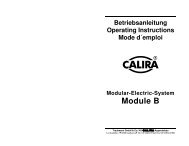
Le tableau de contrôle Module C3 sert à l’affichage de l’état de charge (pos. 2<br />
et 3) de la batterie d’alimentation (batterie II), et sert également de voyant de<br />
contrôle de charge en cas de fonctionnement sur réseau (pos. 4) et de<br />
commutateur principal (pos. 1).<br />
20<br />
Lerchenfeldstr. 9 87600 Kaufbeuren Tel.: +49 (0)8341 9764-0 Fax: +49 (0)8341 67806<br />
1<br />
4<br />
3<br />
2
! !&<br />
# ' ( ) ! ! $<br />
<strong>Co</strong>mmutateur principal<br />
En actionnant le commutateur principal (bouton poussoir allumé, fig. 1 pos. 1),<br />
le relais de commutateur principal s’enclenche dans le Module B. Lorsqu’il est<br />
enclenché, le commutateur principal s’allume en vert. Avec le commutateur<br />
principal, les consommateurs électriques 12 Volts reliés au relais de<br />
commutateur principal peuvent être mis en MARCHE (le bouton poussoir<br />
s’allume en vert) ou à nouveau ARRÊTÉS en actionnant encore une fois ce<br />
commutateur.<br />
Si la tension de la batterie descend en dessous de 10,8 Volts, le relais de<br />
commutateur principal se met automatiquement hors circuit. Si la tension de la<br />
batterie d’alimentation dépasse à nouveau les 12,5 Volts, le relais de<br />
commutateur principal s’enclenche. Lorsque la tension de la batterie se situe<br />
entre les valeurs de 10,8 et 12,5 Volts, il est possible d’activer brièvement<br />
(environ 3 minutes) le relais de commutateur principal en appuyant sur le<br />
bouton poussoir (mode marche d’urgence).<br />
Voyant de contrôle de charge<br />
Le voyant de contrôle de charge (vert, fig. 1 pos. 4) s’allume, indépendamment<br />
du commutateur principal, lorsque le Module B se trouve en mode de charge<br />
réseau et la batterie d’alimentation est en cours de charge. Pour le processus de<br />
charge, reportez-vous à la description du Module B.<br />
Voyant de tension de batterie<br />
En appuyant sur le bouton poussoir (fig. 1 pos. 2), la tension de la batterie<br />
d’alimentation peut être visualisée grâce au voyant de tension de batterie (fig. 1<br />
pos. 3), sous la forme d’une chaîne de DEL.<br />
Segments verts Tension de batterie suffisante<br />
Segments jaunes Tension de batterie critique<br />
Segments rouges Tension de batterie trop faible<br />
L’affichage de la tension de batterie n’est possible que lorsque le commutateur<br />
principal est enclenché.<br />
21<br />
Lerchenfeldstr. 9 87600 Kaufbeuren Tel.: +49 (0)8341 9764-0 Fax: +49 (0)8341 67806
Caractéristiques techniques<br />
Alimentation de<br />
courant :<br />
! !&<br />
# ' ( ) ! ! $<br />
Tension continue 12 V<br />
Réalisation : <strong>Co</strong>nforme aux dispositions de l’Association des<br />
Électrotechniciens Allemands (VDE) et de la loi sur la<br />
sécurité des appareils.<br />
Marque de<br />
conformité :<br />
Utilisation : Pour utilisation dans une caravane, combiné aux MES<br />
Modules A et B.<br />
Plaque frontale : En aluminium, anodisé naturel, rouge<br />
Hauteur : 93 mm Largeur : 88 mm Poids : 70 g (0,7 N)<br />
Montage<br />
Retirer les pièces séparées jointes au carton d’emballage (accessoires) et<br />
vérifier si la livraison est complète.<br />
2 Vis de fixation<br />
1 Câble RS 485 série de transmission de données (4 pôles)<br />
1 Mode d’emploi<br />
Installez le tableau de contrôle en un endroit de la caravane qui soit à l’abri de<br />
l’humidité. Le percement aménagé pour l’insertion du tableau de contrôle doit<br />
avoir une largeur d’environ 68 mm et une hauteur d’environ 60 mm.<br />
22<br />
Lerchenfeldstr. 9 87600 Kaufbeuren Tel.: +49 (0)8341 9764-0 Fax: +49 (0)8341 67806
! !&<br />
# ' ( ) ! ! $<br />
Raccordement<br />
) * ( *<br />
' ) +<br />
# ) ) )<br />
Raccordement au Module B<br />
Assurez-vous que tous les câbles d’alimentation de la batterie et du réseau des<br />
Modules A et B soient déconnectés ou isolés. Reportez-vous aux mode<br />
d’emploi des modules A et B.<br />
Enlevez le couvercle de bornier du Module B. Voir le mode d’emploi du<br />
Module B.<br />
Raccordez le connecteur à 4 pôles du câble RS 485 série de transmission de<br />
données à la fiche du Module B. Voir le mode d’emploi du Module B, schéma<br />
de raccordement (fig. 3 pos. 6).<br />
Raccordez le câble de données RS485 à la fiche à 4 pôles du Module C3. Un<br />
commutateur principal est intégré au Module C3. Si un commutateur principal<br />
était déjà raccordé sur le Module B, il perd toute fonction de par le<br />
raccordement du Module C3 et peut être enlevé.<br />
Travaux finaux<br />
Vérifiez si tous les câbles sont correctement fixés. Remettez le couvercle de<br />
bornier en place. Établissez le raccordement au réseau en dernier.<br />
23<br />
Lerchenfeldstr. 9 87600 Kaufbeuren Tel.: +49 (0)8341 9764-0 Fax: +49 (0)8341 67806
Mise en service<br />
! !&<br />
# ' ( ) ! ! $<br />
Le Module C3 est en service dès que tous les raccordements sont effectués et<br />
que le commutateur principal est actionné.<br />
Mesures à prendre en cas de pannes<br />
Panne Mesure à prendre<br />
Le voyant de<br />
tension n’affiche<br />
rien du tout.<br />
Le voyant de<br />
contrôle de charge<br />
n’affiche rien du<br />
tout.<br />
Le commutateur<br />
principal ne réagit<br />
pas.<br />
Vous n’observez<br />
aucune des pannes<br />
décrites ci-dessus.<br />
Malgré tout,<br />
l’appareil ne<br />
fonctionne pas.<br />
Actionnez le commutateur principal. Vérifiez le<br />
raccordement et le câblage vers le Module B.<br />
Vérifiez le raccordement et le câblage pour le Module B.<br />
Vérifiez le raccordement et le câblage vers le Module B,<br />
ainsi que les fusibles et les raccordements vers les<br />
Modules A et B. Voir aussi le mode d’emploi du Module<br />
B.<br />
Adressez-vous directement au fabricant :<br />
<strong>Trautmann</strong> GmbH & <strong>Co</strong>. <strong>KG</strong><br />
CALIRA-Apparatebau<br />
Lerchenfeldstr. 9<br />
D-87600 Kaufbeuren<br />
Internet : www.calira.de<br />
Adresse électronique : info@calira.de<br />
24<br />
Lerchenfeldstr. 9 87600 Kaufbeuren Tel.: +49 (0)8341 9764-0 Fax: +49 (0)8341 67806
Réparation<br />
! !&<br />
# ' ( ) ! ! $<br />
' $$ # , )#<br />
$ ' ##<br />
Un appareil défectueux ne peut être réparé que par le fabricant ou par son<br />
service après-vente. Respectez ici les consignes générales de sécurité.<br />
Garantie<br />
La garantie est assurée pendant une période de deux ans à compter de la date<br />
d’achat. Les défauts résultant d’un vice de matériel ou de fabrication sont<br />
réparés gratuitement lorsque :<br />
L’appareil a été renvoyé sans frais au fabricant.<br />
La quittance d’achat a été jointe.<br />
L’appareil a été manipulé et utilisé conformément aux prescriptions.<br />
Aucune pièce de rechange étrangère n’a été montée et aucune intervention<br />
n’a été effectuée.<br />
Les frais subséquents et l’usure naturelle ne tombent pas sous le coup de la<br />
garantie.<br />
Important<br />
En cas de mise en valeur de droits relevant de la garantie, il est indispensable<br />
d’effectuer une description détaillée du défaut en question. Des renseignements<br />
détaillés facilitent et accélèrent le traitement. Nous vous prions de bien vouloir<br />
faire preuve de compréhension sur le fait que nous ne pouvons pas accepter<br />
les envois, qui nous parviennent en port dû.<br />
25<br />
Lerchenfeldstr. 9 87600 Kaufbeuren Tel.: +49 (0)8341 9764-0 Fax: +49 (0)8341 67806
* +<br />
! " # ! $<br />
- % . !<br />
## $<br />
Innehållsförteckning<br />
Säkerhetshänvisningar ................................................. 27<br />
Användningsändamål................................................... 27<br />
Beskrivning.................................................................. 28<br />
Huvudströmbrytare................................................. 28<br />
Laddningskontrollindikator.................................... 29<br />
Batterispänningsindikator....................................... 29<br />
Tekniska data ......................................................... 30<br />
Montering .................................................................... 30<br />
Anslutning ................................................................... 31<br />
Driftstart....................................................................... 32<br />
Åtgärder vid driftproblem............................................ 32<br />
Iståndsättning............................................................... 33<br />
Garanti ......................................................................... 33<br />
Senaste ändring: 30.06.2005<br />
Med reservation för tekniska ändringar<br />
26<br />
Lerchenfeldstr. 9 87600 Kaufbeuren Tel.: +49 (0)8341 9764-0 Fax: +49 (0)8341 67806
* +<br />
! " # ! $<br />
Allmänna säkerhetshänvisningar måste läsas noggrant!<br />
OBS!<br />
Vid användning av elektriska apparater måste följande säkerhetsåtgärder<br />
beaktas som skydd mot elektriskt stöt, skador och brandfara. Läs och beakta<br />
dessa hänvisningar innan du använder apparaten.<br />
Uppställning<br />
Se till att apparaten står säkert och inte kan ramla ner eller välta omkull. Lägg<br />
alltid ledningar så att det inte finns risk för att man snubblar över dem. Utsätt<br />
inte elektriska apparater för regn. Använd inte elektriska apparater i fuktig eller<br />
våt omgivning. Använd inte elektriska apparater i närheten av brännbara<br />
vätskor eller gaser. Ställ upp dina elektriska apparater så att barn inte kan<br />
komma åt dem.<br />
Skydd mot elektriskt slag<br />
Använd enbart apparater vars kåpa och ledningar är oskadda. Se upp att<br />
kablarna ligger säkert. Dra aldrig i kablarna.<br />
OBS!<br />
Säkra apparaternas elektriska anslutning med hjälp av en<br />
felströmskyddsbrytare 30 mA nominell felström och använd endast så. Beakta<br />
EVU-föreskrifter.<br />
Användning<br />
Använd elektriska apparater inte till andra ändamål än dem som tillverkaren<br />
har föreskrivit.<br />
Tillbehör<br />
Använd endast tillbehör och tillsatsapparater som har levererats eller<br />
rekommenderats av tillverkaren. Vid användning av andra tillbehör finns risk<br />
för faror.<br />
Användningsändamål<br />
Modular-Electric-System Module C3 kan inte drivas som separat apparat utan<br />
endast tillsammans med Modular-Electric-System Module A och Module B.<br />
Module C3 tjänar som komplettering till de andra modulerna som<br />
kontrolltavla. Module C3 har konstruerats tillsammans med MES Module A<br />
och Module B för användningen i caravan. Modulerna får endast användas i<br />
torra lokaler.<br />
27<br />
Lerchenfeldstr. 9 87600 Kaufbeuren Tel.: +49 (0)8341 9764-0 Fax: +49 (0)8341 67806
Beskrivning<br />
* +<br />
! " # ! $<br />
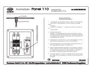
Kontrolltavlan Module C3 fungerar som indikator av försörjningsbatteriets<br />
(batteri II) laddningstillstånd (pos. 2 och 3), som laddningskontrollindikator<br />
vid nätdrift (pos. 4) och som huvudströmbrytare (pos. 1).<br />
Huvudströmbrytare<br />
28<br />
Lerchenfeldstr. 9 87600 Kaufbeuren Tel.: +49 (0)8341 9764-0 Fax: +49 (0)8341 67806<br />
1<br />
Bild 1: Module C3<br />
Genom att trycka huvudströmbrytaren (belyst tryckknapp bild 1 pos. 1)<br />
aktiveras huvudströmbrytarreläet i Module B. Huvudströmbrytaren lyser grönt<br />
när den är aktiverad. Med huvudströmbrytaren kan du tillsammans med<br />
huvudströmbrytarreläet sätta PÅ (tryckknappen lyser grönt) och genom ett nytt<br />
tryck stänga AV 12 volt förbrukarna.<br />
Sjunker försörjningsbatteriets spänning under 10,8 volt så stängs<br />
huvudströmbrytarreläet av automatiskt. När försörjningsbatteriet stiger<br />
över 12,5 volt igen så sätts huvudströmbrytarreläet på igen. Mellan en<br />
batterispänning på 10,8 volt och 12,5 volt kan du tillfälligt (c:a 3 minuter)<br />
4<br />
3<br />
2
* +<br />
! " # ! $<br />
aktivera huvudströmbrytarreläet genom att trycka på tryckknappen. (funktion<br />
för nödpåsättning).<br />
Laddningskontrollindikator<br />
Laddningskontrollindikatorn (grön, bild 1 pos. 4) lyser, oberoende av<br />
huvudströmbrytaren, när Module B är i nätladdningsdrift och försörjningsbatteriet<br />
laddas. Laddningsprocess se beskrivning Module B.<br />
Batterispänningsindikator<br />
Genom att trycka knappen (bild 1 pos. 2) visas försörjningsbatteriets spänning i<br />
batterispänningsindikatorn (bild 1 pos. 3) med en LED-kedja.<br />
Grönt område batterispänning tillräcklig<br />
Gult område batterispänning kritisk<br />
Rött område batterispänning för låg<br />
Batterispänningsindikatorn fungerar endast när huvudströmbrytaren är på.<br />
29<br />
Lerchenfeldstr. 9 87600 Kaufbeuren Tel.: +49 (0)8341 9764-0 Fax: +49 (0)8341 67806
Tekniska data<br />
Strömförsörjning: Likspänning 12 V<br />
* +<br />
! " # ! $<br />
Genomföring: enligt VDE:s bestämmelser och säkerhetslagen för<br />
apparater.<br />
Kontrolltecken:<br />
Användning: Till användning i caravan i kombination med MES<br />
Module A och B<br />
Frontplatta: Aluminium, natur anodoxiderad, med tryck<br />
Höjd: 93 mm Bredd: 88 mm Vikt: 70 g (0,7 N)<br />
Montering<br />
Ta ut tillbehör ur kartongen och kontrollera att allting är fullständigt.<br />
2 fästskruvar<br />
1 seriell RS485 dataledningskabel (4-polig)<br />
1 Bruksanvisning<br />
Montera kontrolltavlan i caravanen på en plats som inte är utsatt för fuktighet.<br />
Utskärningen för kontrolltavlans inbyggnad måste vara c:a 68 mm bred och c:a<br />
60 mm hög.<br />
30<br />
Lerchenfeldstr. 9 87600 Kaufbeuren Tel.: +49 (0)8341 9764-0 Fax: +49 (0)8341 67806
Anslutning<br />
* +<br />
! " # ! $<br />
! ## .<br />
$ . ! / $0 0 /<br />
Anslutning till Module B<br />
Kontrollera att batteriets och nätets samtliga försörjningsledningar på Module<br />
A och B har stängts av respektive har kopplats loss. Se bruksanvisningen<br />
Module A och B.<br />
Ta bort kopplingsdosans lock på Module B. Se bruksanvisning Module B.<br />
Anslut den seriella RS 485 dataöverföringsledningens 4-poliga kontakt till<br />
Module B:s kontakt. Se bruksanvisning Module B anslutningsplan (bild 3 pos.<br />
6).<br />
Anslut den seriella dataledningen RS485 till Module C3:s 4-poliga kontakt. På<br />
Module C3 finns en integrerad huvudströmbrytare. Om en separat<br />
huvudströmbrytare redan har anslutits till Module B så förlorar denna sin<br />
funktion i och med att en Module C3 ansluts och kan därför tas bort.<br />
Avslutande arbeten<br />
Kontrollera att samtliga ledningar sitter fast. Montera kopplingsdosans lock.<br />
Anslut till nätet till slut.<br />
31<br />
Lerchenfeldstr. 9 87600 Kaufbeuren Tel.: +49 (0)8341 9764-0 Fax: +49 (0)8341 67806
Driftstart<br />
* +<br />
! " # ! $<br />
Module C3 är i drift så fort anslutningarna har monterats och<br />
huvudströmbrytaren är på.<br />
Åtgärder vid driftproblem<br />
Störning Åtgärd<br />
Spänningsindikatorn<br />
indikerar inte.<br />
Laddningskontroll<br />
indikatorn<br />
indikerar inte.<br />
Huvudströmbrytaren<br />
reagerar<br />
inte.<br />
Du kan inte<br />
fastställa en av<br />
störningarna som<br />
beskrivs här. Ändå<br />
fungerar apparaten<br />
inte.<br />
Aktivera huvudströmbrytaren. Kontrollera anslutningen<br />
och ledningen till Module B.<br />
Kontrollera anslutningen och ledningen för Module B.<br />
Kontrollera anslutningen och ledningen till Module B<br />
samt Module A:s och B:s säkringar och anslutningar. Se<br />
också bruksanvisning Module B.<br />
Kontakta tillverkaren:<br />
<strong>Trautmann</strong> GmbH & <strong>Co</strong>. <strong>KG</strong><br />
CALIRA-Apparatebau<br />
Lerchenfeldstr. 9<br />
87600 Kaufbeuren<br />
Hemsida: www.calira.de<br />
E-post: info@calira.de<br />
32<br />
Lerchenfeldstr. 9 87600 Kaufbeuren Tel.: +49 (0)8341 9764-0 Fax: +49 (0)8341 67806
Iståndsättning<br />
* +<br />
! " # ! $<br />
$0 . $0<br />
#. ##<br />
En defekt apparat kan endast iståndsättas av tillverkaren eller dess service.<br />
Beakta de allmänna säkerhetsföreskrifterna.<br />
Garanti<br />
Garanti beviljas för en tidsperiod på två år från och med inköpstillfälle. Brister<br />
på grund av material- eller tillverkningsfel avlägsnas kostnadsfritt i följande<br />
fall:<br />
Apparaten skickas till tillverkaren kostnadsfritt.<br />
Köpebevis har bifogats.<br />
Apparaten har hanterats och använts ändamålsenligt.<br />
Inga främmande reservdelar har byggts in, inga förändringar har<br />
genomförts.<br />
Följdkostnader och naturlig slitning ingår inte i garantin.<br />
Viktigt<br />
När du ställer garantikrav är det absolut nödvändigt att respektive brist<br />
beskrivs utförligt. Detaljerade informationer underlättar och påskyndar<br />
bearbetningen. Vänligen har förståelse för att vi inta kan ta emot ofrankerade<br />
postförsändelser.<br />
33<br />
Lerchenfeldstr. 9 87600 Kaufbeuren Tel.: +49 (0)8341 9764-0 Fax: +49 (0)8341 67806
* +<br />
! " # ! $<br />
34<br />
Lerchenfeldstr. 9 87600 Kaufbeuren Tel.: +49 (0)8341 9764-0 Fax: +49 (0)8341 67806
* +<br />
! " # ! $<br />
35<br />
Lerchenfeldstr. 9 87600 Kaufbeuren Tel.: +49 (0)8341 9764-0 Fax: +49 (0)8341 67806
Reparatur Rücksendeschein Repairs return voucher<br />
Réparation - Bon de renvoi Reparation returblankett<br />
Wichtig! Important! Viktigt!<br />
. 0 !<br />
(<br />
! "#<br />
$ #<br />
$ % #<br />
& ' #<br />
! ( ) *<br />
* + !<br />
$ $ ,<br />
, - ./ ,<br />
1 " 1 " 1 " 1 "<br />
- 2 1 - " Rue et n° Gata och nr.<br />
345 6 7 8 0 4<br />
7 7 7<br />
<strong>Trautmann</strong> GmbH & <strong>Co</strong>. <strong>KG</strong><br />
B50 080004 00