AC 65/180 AC 65/180 X AC 80/180 AC 80/180 X AC 110/180 X
AC 65/180 AC 65/180 X AC 80/180 AC 80/180 X AC 110/180 X
AC 65/180 AC 65/180 X AC 80/180 AC 80/180 X AC 110/180 X

You also want an ePaper? Increase the reach of your titles
YUMPU automatically turns print PDFs into web optimized ePapers that Google loves.
deutsch<br />
français<br />
italiano<br />
english<br />
nederlands<br />
español<br />
<strong>AC</strong> <strong>65</strong>/<strong>1<strong>80</strong></strong><br />
<strong>AC</strong> <strong>65</strong>/<strong>1<strong>80</strong></strong> X<br />
<strong>AC</strong> <strong>80</strong>/<strong>1<strong>80</strong></strong><br />
<strong>AC</strong> <strong>80</strong>/<strong>1<strong>80</strong></strong> X<br />
<strong>AC</strong> <strong>110</strong>/<strong>1<strong>80</strong></strong> X<br />
Umwälzpumpen<br />
Montage- und Betriebsanleitung Seite 4<br />
Circulateurs<br />
Instructions d’installation<br />
et d’entretien Page 20<br />
Pompe di circolazione<br />
Istruzioni di installazione<br />
e funzionamento Pag. 36<br />
Circulation Pumps<br />
Installation and Operating<br />
Instructions Page 52<br />
Circulatiepompen<br />
Montage- en bedrijfsinstructies Pag. 68<br />
Bombas de circulación<br />
Instrucciones de instalación<br />
y funcionamiento Pág. 84<br />
®
2<br />
Konformitäts-Erklärung<br />
Wir DAB Pumps S.p.A. erklären in alleiniger<br />
Verantwortung, dass das Produkte<br />
<strong>AC</strong> <strong>65</strong>/<strong>1<strong>80</strong></strong>, <strong>AC</strong> <strong>65</strong>/<strong>1<strong>80</strong></strong> X<br />
<strong>AC</strong> <strong>80</strong>/<strong>1<strong>80</strong></strong>, <strong>AC</strong> <strong>80</strong>/<strong>1<strong>80</strong></strong> X, <strong>AC</strong> <strong>110</strong>/<strong>1<strong>80</strong></strong> X<br />
auf die sich diese Erklärung bezieht, mit folgenden<br />
Richtlinien des Rates zur Angleichung<br />
der Rechtsvorschriften der EG Mitgliedstaaten<br />
übereinstimmen:<br />
– Maschinen (98/37/EG)<br />
– Elektrische Betriebsmittel zur Verwendung<br />
innerhalb bestimmter Spannungsgrenzen<br />
(2006/95/EG)<br />
Normen: EN 60335-1:2002, EN 60335-2-51:2003<br />
– Elektromagnetische Verträglichkeit (2004/108/EG)<br />
Normen: EN 61000-6-2, EN 61000-6-3<br />
Dichiarazione di Conformità<br />
Noi, ditta DAB Pumps S.p.A., dichiariamo sotto<br />
la nostra esclusiva responsabilità che i prodotti<br />
<strong>AC</strong> <strong>65</strong>/<strong>1<strong>80</strong></strong>, <strong>AC</strong> <strong>65</strong>/<strong>1<strong>80</strong></strong> X<br />
<strong>AC</strong> <strong>80</strong>/<strong>1<strong>80</strong></strong>, <strong>AC</strong> <strong>80</strong>/<strong>1<strong>80</strong></strong> X, <strong>AC</strong> <strong>110</strong>/<strong>1<strong>80</strong></strong> X<br />
ai quali questa dichiarazione si riferisce,<br />
sono conformi alle direttive del Consiglio,<br />
concernenti il ravvicinamento delle legislazioni<br />
degli Stati membri CE relativi a:<br />
– Macchine (98/37/CE)<br />
– Materiale elettrico destinato ad essere utilizzato<br />
entro certi limiti di tensione (2006/95/EG)<br />
Norme: EN 60335-1:2002, EN 60335-2-51:2003<br />
– Compatibilità elettromagnetica (2004/108/EG)<br />
Norme: EN 61000-6-2, EN 61000-6-3<br />
Overeenkomstigheidsverklaring<br />
Wij DAB Pumps S.p.A. verklaren geheel onder<br />
eigen verantwoordelijkheid dat de produkten<br />
<strong>AC</strong> <strong>65</strong>/<strong>1<strong>80</strong></strong>, <strong>AC</strong> <strong>65</strong>/<strong>1<strong>80</strong></strong> X<br />
<strong>AC</strong> <strong>80</strong>/<strong>1<strong>80</strong></strong>, <strong>AC</strong> <strong>80</strong>/<strong>1<strong>80</strong></strong> X, <strong>AC</strong> <strong>110</strong>/<strong>1<strong>80</strong></strong> X<br />
waarop deze verklaring betrekking heeft<br />
in overeenstemming zijn met de Richtlijnen<br />
van de Raad inzake de onderlinge aanpassing<br />
van de wetgevingen van de Lid-Staten betreffende<br />
– Maschines (98/37/CE)<br />
– Elektrisch materiaal bestemd voor gebruik binnen<br />
bepaalde spanningsgrenzen (2006/95/EG)<br />
Normen: EN 60335-1:2002, EN 60335-2-51:2003<br />
– Elektromagnetische compatibiliteit (2004/108/EG)<br />
Normen: EN 61000-6-2, EN 61000-6-3<br />
Mestrino, 1st April 2008<br />
Déclaration de conformité<br />
Nous, l’entreprise DAB Pumps S.p.A., déclarons<br />
sous notre seule responsabilité que les produits<br />
<strong>AC</strong> <strong>65</strong>/<strong>1<strong>80</strong></strong>, <strong>AC</strong> <strong>65</strong>/<strong>1<strong>80</strong></strong> X<br />
<strong>AC</strong> <strong>80</strong>/<strong>1<strong>80</strong></strong>, <strong>AC</strong> <strong>80</strong>/<strong>1<strong>80</strong></strong> X, <strong>AC</strong> <strong>110</strong>/<strong>1<strong>80</strong></strong> X<br />
auxquels se réfère cette déclaration<br />
sont conformes aux Directives du Conseil<br />
concernant le rapprochement des législations<br />
des Etats membres CE relatives à:<br />
– Machines (98/37/CE)<br />
– Matériel électrique destiné à employer<br />
dans certaines limites de tension (2006/95/EG)<br />
Normes: EN 60335-1:2002, EN 60335-2-51:2003<br />
– Compatibilité électromagnétique (2004/108/EG)<br />
Normes: EN 61000-6-2, EN 61000-6-3<br />
Declaration of Conformity<br />
We, the DAB Pumps S.p.A. declare under<br />
our sole responsibility that the products<br />
<strong>AC</strong> <strong>65</strong>/<strong>1<strong>80</strong></strong>, <strong>AC</strong> <strong>65</strong>/<strong>1<strong>80</strong></strong> X<br />
<strong>AC</strong> <strong>80</strong>/<strong>1<strong>80</strong></strong>, <strong>AC</strong> <strong>80</strong>/<strong>1<strong>80</strong></strong> X, <strong>AC</strong> <strong>110</strong>/<strong>1<strong>80</strong></strong> X<br />
to which this declaration relates, are in conformity<br />
with the Council Directives on the approximation<br />
of the laws of the EC Member States relating to:<br />
– Machinery (98/37/EC)<br />
– Electrical equipment designed<br />
for use within certain voltage limits (2006/95/EG)<br />
Standards: EN 60335-1:2002, EN 60335-2-51:2003<br />
– Electromagnetic compatibility (2004/108/EG)<br />
Standards: EN 61000-6-2, EN 61000-6-3<br />
Declaración de conformidad<br />
La empresa que suscribe, DAB Pumps S.p.A.,<br />
declara bajo su exclusiva responsabilidad<br />
la conformidad de los productos<br />
<strong>AC</strong> <strong>65</strong>/<strong>1<strong>80</strong></strong>, <strong>AC</strong> <strong>65</strong>/<strong>1<strong>80</strong></strong> X<br />
<strong>AC</strong> <strong>80</strong>/<strong>1<strong>80</strong></strong>, <strong>AC</strong> <strong>80</strong>/<strong>1<strong>80</strong></strong> X, <strong>AC</strong> <strong>110</strong>/<strong>1<strong>80</strong></strong> X<br />
a los que se refiere esta declaración,<br />
con las disposiciones de las siguientes Directivas<br />
del Consejo relativas a la aproximación<br />
de las legislaciones de los Estados Miembros<br />
de la CE:<br />
– Máquinas (98/37/CE)<br />
– Material eléctrico para uso dentro<br />
de determinados límites de tensión (2006/95/CE)<br />
Normas: EN 60335-1:2002, EN 60335-2-51:2003<br />
– Compatibilidad electromagnética (2004/108/CE)<br />
Normas: EN 61000-6-2, EN 61000-6-3<br />
Attilio Conca<br />
Legal Representative
3<br />
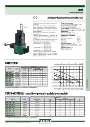
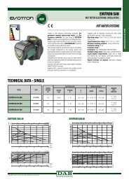
Abmessungen Typenreihe<br />
Dimensions Série<br />
Dimensioni Gamma<br />
Dimensions Series<br />
Afmetingen Serie<br />
Dimension Series<br />
<strong>AC</strong> <strong>65</strong><br />
<strong>AC</strong> <strong>80</strong><br />
<strong>AC</strong> <strong>110</strong><br />
<strong>AC</strong> <strong>65</strong>/<strong>1<strong>80</strong></strong> <strong>AC</strong> <strong>65</strong>/<strong>1<strong>80</strong></strong> X <strong>AC</strong> <strong>80</strong>/<strong>1<strong>80</strong></strong> <strong>AC</strong> <strong>80</strong>/<strong>1<strong>80</strong></strong> X <strong>AC</strong> <strong>110</strong>/<strong>1<strong>80</strong></strong> X<br />
PN 10 PN 10 PN 10 PN 10 PN 16<br />
∅ 3 /4…1” 3 1 /4…1 /2” 3 /4…1” 3 1 /4…1 /2” 3 1 /4…1 /2”<br />
D 11 /2” 2” 11 /2” 2” 2”<br />
B1 188 188 188 188 188<br />
B2 92 92 92 92 92<br />
B3 137 137 137 137 137<br />
H 235 245 235 245 245<br />
L <strong>1<strong>80</strong></strong> <strong>1<strong>80</strong></strong> <strong>1<strong>80</strong></strong> <strong>1<strong>80</strong></strong> <strong>1<strong>80</strong></strong><br />
T1 201 201 201 201 201<br />
T2 49 49 49 49 49<br />
T3 152 152 152 152 152<br />
kg 3,8 3,8 3,8 3,8 3,8<br />
B2<br />
B1<br />
H<br />
960935_00<br />
T2 T3<br />
L<br />
D<br />
T1<br />
3<br />
B<br />
max. Ø10
4<br />
deutsch<br />
Inhaltsverzeichnis<br />
1. Sicherheitshinweise Seite 5<br />
1.1 Allgemeines 5<br />
1.2 Kennzeichnung von Hinweisen 5<br />
1.3 Personalqualifikation und -schulung 5<br />
1.4 Gefahren bei Nichtbeachtung<br />
der Sicherheitshinweise 5<br />
1.5 Sicherheitsbewusstes Arbeiten 6<br />
1.6 Sicherheitshinweise für den Betreiber/Bediener 6<br />
1.7 Sicherheitshinweise für Montage-,<br />
Wartungs- und Inspektionsarbeiten 6<br />
1.8 Eigenmächtiger Umbau und Ersatzteilherstellung 6<br />
1.9 Unzulässige Betriebsweisen 6<br />
2. Transport/Lagerung 6<br />
3. Verwendungszweck 7<br />
3.1 Fördermedium 7<br />
3.2 Betriebstemperatur/Betriebsdruck 7<br />
4. Montage 7<br />
4.1 Durchspülen der Heizungsanlage 7<br />
4.2 Frostschutzmittel (sofern erforderlich) 7<br />
4.3 Einbau 7<br />
4.4 Montageposition 8<br />
4.5 Rückschlagventil 8<br />
4.6 Mindestdruck 9<br />
5. Elektrischer Anschluss 9<br />
5.1 Anschlussklemmen 10<br />
5.2 Anschlussschema Standardausführung 11<br />
5.3 Leistungsbegrenzung, Minimaldrehzahl 11<br />
5.4 Zusatzmodule 12<br />
5.4.1 Anschlussschema Steuer-Modul (optional) 12<br />
5.4.2 Anschlussschema Signal-Modul (optional) 12<br />
5.4.3 Anschlussschema Zwillingspumpensteuerung 12<br />
5.5 Weitere Einstellungen 13<br />
5.5.1 Einstellung der Regelungsart (A1) 13<br />
5.5.2 Einstellung der Förderhöhe (A2) 14<br />
5.5.3 Weitere Leuchtsymbole (A3) 14<br />
5.6 Werkseitige Einstellung der Pumpe 14<br />
5.7 Anzeige der verschiedenen Regelkennlinien zu <strong>AC</strong> <strong>80</strong> 15<br />
5.7.1 Proportionaldruck-Regelung 15<br />
5.7.2 Konstantdruck-Regelung 15<br />
5.7.3 Konstante Drehzahl 15<br />
6. Inbetriebnahme/Betriebskontrolle 16<br />
6.1 Allgemeines 16<br />
6.2 Entlüften 16<br />
6.3 Betriebskontrolle 16<br />
6.4 Deblockieren 16<br />
7. Wartung, Service 16<br />
8. Störungsübersicht 17<br />
9. Isolationswiderstandsprüfung 18<br />
10. Technische Daten 19<br />
11. Entsorgung 19
5<br />
deutsch<br />
1. Sicherheitshinweise<br />
1.1 Allgemeines<br />
Diese Montage- und Betriebsanleitung enthält grundlegende<br />
Hinweise, die bei Aufstellung, Betrieb und Wartung zu beachten<br />
sind. Sie ist daher unbedingt vor Montage und Inbetriebnahme<br />
vom Monteur sowie dem zuständigen Fachpersonal/Betreiber<br />
zu lesen. Sie muss ständig am Einsatzort der Anlage verfügbar<br />
sein.<br />
Es sind nicht nur die unter diesem Abschnitt «Sicherheitshinweise»<br />
aufgeführten, allgemeinen Sicherheitshinweise zu<br />
beachten, sondern auch die unter den anderen Abschnitten eingefügten,<br />
speziellen Sicherheitshinweise.<br />
1.2 Kennzeichnung von Hinweisen<br />
Achtung<br />
Die in dieser Montage- und Betriebsanleitung<br />
enthaltenen Sicherheitshinweise, die bei Nichtbeachtung<br />
Gefährdungen für Personen hervorrufen<br />
können, sind mit allgemeinem Gefahrensymbol<br />
«Sicherheitszeichen nach DIN 4844-W9»<br />
besonders gekennzeichnet.<br />
Dieses Symbol steht für Warnung vor<br />
gefährlicher elektrischer Spannung.<br />
«Sicherheitszeichen nach DIN 4844-W8».<br />
Dieses Symbol finden Sie bei Sicherheitshinweisen,<br />
deren Nichtbeachtung Gefahren für<br />
die Maschine und deren Funktionen hervorrufen<br />
kann.<br />
Direkt an der Anlage angebrachte Hinweise wie zum Beispiel<br />
– Drehrichtungspfeil<br />
– Kennzeichen für Fluidanschlüsse<br />
müssen unbedingt beachtet und in vollständig lesbarem<br />
Zustand gehalten werden.<br />
1.3 Personalqualifikation und -schulung<br />
Das Personal für Montage, Bedienung, Wartung und Inspektion<br />
muss die entsprechende Qualifikation für diese Arbeiten aufweisen.<br />
Verantwortungsbereich, Zuständigkeit und die Überwachung<br />
des Personals müssen durch den Betreiber genau<br />
geregelt sein.<br />
1.4 Gefahren bei Nichtbeachtung der Sicherheitshinweise<br />
Die Nichtbeachtung der Sicherheitshinweise kann sowohl eine<br />
Gefährdung für Personen als auch für die Umwelt und Anlage zur<br />
Folge haben. Die Nichtbeachtung der Sicherheitshinweise kann<br />
zum Verlust jeglicher Schadenersatzansprüche führen.
6<br />
deutsch<br />
Im einzelnen kann Nichtbeachtung beispielsweise folgende<br />
Gefährdungen nach sich ziehen:<br />
– Versagen wichtiger Funktionen in der Anlage<br />
– Versagen vorgeschriebener Methoden<br />
zur Wartung und Instandhaltung<br />
– Gefährdung von Personen durch elektrische und mechanische<br />
Einwirkungen<br />
1.5 Sicherheitsbewusstes Arbeiten<br />
Die in dieser Montage- und Betriebsanleitung aufgeführten<br />
Sicherheitshinweise, die bestehenden nationalen Vorschriften<br />
zur Unfallverhütung sowie eventuelle interne Arbeits-, Betriebsund<br />
Sicherheitsvorschriften des Betreibers, sind zu beachten.<br />
1.6 Sicherheitshinweise für den Betreiber/Bediener<br />
Gefährdungen durch elektrische Energie sind auszuschliessen<br />
(Einzelheiten hierzu siehe zumBeispiel in den Vorschriften des<br />
NIN (CENELEC) und der örtlichen Energieversorgungsunternehmen).<br />
1.7 Sicherheitshinweise für Montage-, Wartungs-<br />
und Inspektionsarbeiten<br />
Der Betreiber hat dafür zu sorgen, dass alle Montage-,<br />
Wartungs- und Inspektionsarbeiten von autorisiertem und<br />
qualifiziertem Fachpersonal ausgeführt werden, das sich durch<br />
eingehendes Studium der Montage- und Betriebsanleitung ausreichend<br />
informiert hat.<br />
Grundsätzlich sind arbeiten an der Anlage nur im Stillstand<br />
durchzuführen.<br />
Unmittelbar nach Abschluss der Arbeiten müssen alle<br />
Sicherheits- und Schutzeinrichtungen wieder angebracht bzw.<br />
in Funktion gesetzt werden.<br />
Vor der Wiederinbetriebnahme sind die im Abschnitt<br />
«Elektrischer Anschluss» aufgeführten Punkte zu beachten.<br />
1.8 Eigenmächtiger Umbau und Ersatzteilherstellung<br />
Umbau oder Veränderungen an Pumpen sind nur nach<br />
Absprache mit dem Hersteller zulässig. Originalersatzteile und<br />
vom Hersteller autorisiertes Zubehör dienen der Sicherheit.<br />
Die Verwendung anderer Teile kann die Haftung für die daraus<br />
entstehenden Folgen aufheben.<br />
1.9 Unzulässige Betriebsweisen<br />
Die Betriebssicherheit der gelieferten Pumpen ist nur bei<br />
bestimmungsgemässer Verwendung entsprechend Abschnitt<br />
«Verwendungszweck» der Montage- und Betriebsanleitung<br />
gewährleistet. Die in den technischen Daten angegebenen<br />
Grenzwerte dürfen auf keinen Fall überschritten werden.<br />
2. Transport/Lagerung<br />
Die Pumpen werden vom Werk in einer zweckmässigen<br />
Verpackung geliefert.
7<br />
deutsch<br />
3. Verwendungszweck<br />
Die DAB-Umwälzpumpen der Typenreihe<br />
<strong>AC</strong> <strong>65</strong>, <strong>AC</strong> <strong>80</strong>, <strong>AC</strong> <strong>110</strong><br />
umfasst einen Permanentmagnet-Motor mit Spaltrohr<br />
und einen integrierten Frequenzumformer mit Konstantdruck-,<br />
Proportionaldruck- und Konstantdrehzahlregelung.<br />
Die Pumpe wird verwendet zur Förderung von Flüssigkeiten in:<br />
– Warmwasser-Heizungsanlagen<br />
– geschlossenen industriellen Umwälzsystemen<br />
– Trinkwasseranlagen (AW)<br />
3.1 Fördermedium<br />
In Heizungsanlagen soll das Fördermedium den Anforderungen<br />
von Heizungswasser gemäss VDI 2035 entsprechen.<br />
Wasser-/Glykol-Gemisch zulässig bis 50% Glykolanteil.<br />
In Trinkwasseranlagen darf die Pumpe nur bei Wasser<br />
mit Härtegrad
8<br />
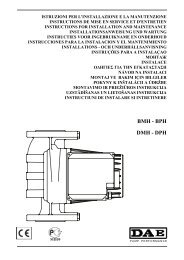
4.4 Montageposition<br />
Lieferzustand<br />
Kabelverschraubung links<br />
Durchflussrichtung<br />
Der Pfeil auf dem Pumpengehäuse<br />
zeigt die<br />
Durchflussrichtung an.<br />
Der Klemmenkasten darf<br />
nicht nach oben zeigen,<br />
da sonst leicht Wasser<br />
eindringen kann.<br />
Vor der Montage der Pumpe<br />
kann der Klemmenkasten<br />
jeweils um 90° gedreht<br />
werden.<br />
Hierzu die 4 Schrauben des<br />
Gehäuses lösen und den<br />
Motorkopf in die zulässige<br />
Klemmenkasten-Position<br />
drehen.<br />
Dichtung zwischen Motor<br />
und Pumpengehäuse<br />
nicht verschieben oder<br />
beschädigen.<br />
Nach dem Einsetzen der<br />
Schrauben diese übers Kreuz<br />
anziehen.<br />
Der Pfeil auf dem Pumpengehäuse<br />
zeigt die<br />
Durchflussrichtung an.<br />
Die Welle muss immer<br />
waagrecht sein,<br />
nie senkrecht.<br />
4.5 Rückschlagventil<br />
Falls ein Rückschlagventil<br />
montiert ist, muss die Pumpe<br />
so eingestellt werden<br />
(siehe Punkt 5.4.2), dass<br />
der minimale Förderdruck<br />
der Pumpe jederzeit den<br />
Schliessdruck des Ventils<br />
übersteigt.<br />
deutsch
9<br />
deutsch<br />
Absperrschieber vor und nach der Pumpe einbauen.<br />
Damit wird bei einem möglichen Austausch der Pumpe ein<br />
Ablassen und Wiederauffüllen der Anlage vermieden.<br />
4.6 Mindestdruck<br />
Der Mindestdruck am Pumpensaugstutzen bei 75 °C<br />
zur sicheren Schmierung der Gleitlager:<br />
Die Werte gelten bis 500 m über Meeresspiegel.<br />
Zuschlag für grössere Höhen:<br />
0,01 bar pro 100 m Höhenzuwachs<br />
bei 75 °C 0,10 bar<br />
90 °C 0,55 bar<br />
<strong>110</strong> °C 1,20 bar<br />
5. Elektrischer Anschluss<br />
Der elektrische Anschluss muss von einem Fachmann<br />
ausgeführt werden.<br />
Die Vorschriften des örtlichen Energieversorgungsunternehmens<br />
(EVU) sind zu beachten.<br />
NIN (CENELEC)-Vorschriften beachten.<br />
Bei höheren Wassertemperaturen (ab <strong>80</strong> °C) entsprechend<br />
wärmebeständige Anschlussleitung verwenden.<br />
Die Anschlussleitung darf die Rohrleitung, das Pumpen-<br />
und Motorgehäuse nicht berühren.<br />
Tropfwasserschutz und Zugentlastung bei Kabeleinführung<br />
in Anschlusskasten (Stopfbuchse) beachten!<br />
Vorsicherung: (Nennstrom ×1,5) max. 10 A, träge<br />
Drahtquerschnitt: max. 1,5 mm 2<br />
Der elektrische Anschluss hat gemäss Datenschild zu erfolgen.<br />
Für spätere einfache Auswechslung ist der elektrische Anschluss<br />
zu schlaufen. Es muss darauf geachtet werden, dass die elektrischen<br />
Daten auf dem Typenschild der Pumpe mit der gegebenen<br />
Stromversorgung übereinstimmen.<br />
Hinweis: Besondere Beachtung gilt dem Schutzleiteranschluss.<br />
Der Schutzleiter muss länger als die Polleiter sein (Ausreissgefahr).<br />
Versorgungsspannung:<br />
1×230-240 V +6%/–10%, 50/60 Hz, PE<br />
<strong>AC</strong> <strong>65</strong> <strong>AC</strong> <strong>80</strong> <strong>AC</strong> <strong>110</strong><br />
Nennstrom Regelung 0,1…0,48 A 0,1…0,77 A 0,1…1,24 A<br />
min. 0,14 A 0,14 A 0,14 A<br />
Leistung Regelung 8...70 W 8...107 W 8...174 W<br />
min. 8...19 W 8...19 W 8...19 W
10<br />
960940_00<br />
deutsch<br />
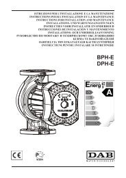
5.1 Anschlussklemmen<br />
Netzanschluss 1×230-240 V<br />
Schutzleiter<br />
L Leiter<br />
N Neutralleiter<br />
1×230-240 V +6/–10%, 50/60 Hz<br />
Beim Einsatz von Fehlerstrom-Schutzschalter (FI) muss eine<br />
pulsstromsensitive Ausführung verwendet werden,<br />
die bei Netzeinschaltung den Ladestromimpuls gegen Erde<br />
berücksichtigen und die für den Ableitstrom kleiner 3,5 mA<br />
der Pumpe geeignet sind.<br />
Die FI-Schalter müssen mit dem gezeigten Symbol<br />
gekennzeichnet sein.<br />
Bemerkung:<br />
Vor jedem Eingriff in den Klemmenkasten der Pumpe muss die<br />
Versorgungsspannung abgeschaltet werden.<br />
Klemmenkasten öffnen<br />
Schrauben: Torx 20<br />
Deckel aufklappen<br />
Bei falschem Anschluss und falscher Spannung<br />
kann die Elektronik beschädigt werden!<br />
Vorsicht beim Öffnen des Elektronik-Deckels!<br />
Elektronik kann bis zu 10 Minuten nach dem<br />
Ausschalten des Stromes unter Spannung sein<br />
Etikette im Deckel<br />
mit Typ, Version, Produktionsdatum
11 deutsch<br />
Anschlussschema 1)<br />
51-54 Störmeldung<br />
(Potentialfreier<br />
Schliesskontakt<br />
bei Störung geschlossen)<br />
Kontaktbelastung<br />
max. 250V~, 1A<br />
51-52 Störmeldung<br />
(Potentialfreier<br />
Öffnerkontakt<br />
bei Störung offen)<br />
Kontaktbelastung<br />
max. 250V~, 1A<br />
Switch<br />
OFF<br />
ON<br />
5.2 Anschlussschema Standardausführung<br />
54 52 51<br />
max. 250V<br />
1A<br />
N L<br />
Speisung<br />
~1×230 V<br />
Vorsicherung<br />
10 A<br />
Switch<br />
Switch ON OFF<br />
1 Leistungsbegrenzung Leistungsbegrenzung<br />
EIN (ON) AUS (OFF)<br />
2 Klemmen 51, 52, 54 Klemmen 51, 52, 54<br />
1) Betriebsmeldung Störmeldung<br />
Bemerkungen Switch Einstellungen:<br />
1) Die Leistungsbegrenzung Pred ist serienmässig eingestellt<br />
auf <strong>80</strong>% von P max um Geräusche durch eine zu hohe<br />
Fördermenge V [m 3 /h] der Pumpe zu vermeiden.<br />
Kann bei Bedarf auf max. Fördermenge der Pumpe umgestellt<br />
werden.<br />
0<br />
0<br />
_<br />
1<br />
4<br />
9<br />
0<br />
6<br />
9<br />
= Lieferzustand<br />
5.3 Leistungsbegrenzung, Minimaldrehzahl:<br />
Die Pumpe kann auf eine Minimaldrehzahl (min) eingestellt<br />
werden.<br />
Minimaldrehzahl (min )<br />
Leistungsbegrenzung (P red)
12 deutsch<br />
81-82 Multitherm/PWM<br />
Eingang für externe<br />
Drehzahlvorgabe<br />
71-72 Ananlogeingang 0…10V<br />
oder 0…20 mA<br />
für externe<br />
Drehzahlvorgabe<br />
10-11 Steuerkontakt<br />
für externes<br />
Ausschalten der Pumpe<br />
91-92 Doppelpumpe<br />
10-11 Steuerkontakt<br />
für externes<br />
Ausschalten der Pumpe<br />
10-13 Steuerkontakt<br />
für externe Ein-<br />
und Ausschaltung<br />
der Minimaldrehzahl<br />
91-92 Doppelpumpe<br />
61-64 Betriebs- oder<br />
Bereitmeldung<br />
(Schliesser)<br />
61-62 Betriebs- oder<br />
Bereitmeldung<br />
(Öffner)<br />
Funktion<br />
nur mit Steueroder<br />
Signalmodul<br />
91-92 Doppelpumpe<br />
Technische Details<br />
Zusatzmodule siehe<br />
«Betriebsanleitung<br />
Zusatzmodul»<br />
5.4 Zusatzmodule<br />
5.4.1 Anschlussschema Steuer-Modul (optional)<br />
961177_00<br />
81 82 71 72 11 10 91 92<br />
5.4.2 Anschlussschema Signal-Modul (optional)<br />
961178_00<br />
13 11 10 91 92 64 62<br />
61<br />
5.4.3 Anschlussschema Zwillingspumpensteuerung<br />
91 92 91 92<br />
N L N L<br />
961175_00
13 deutsch<br />
Zyklus<br />
der Regelungsart<br />
LED<br />
V .<br />
5.5 Weitere Einstellungen<br />
A) Bedientastatur<br />
B) Firmenschild<br />
Es besteht Verbrennungsgefahr!<br />
Bei hohen Medientemperaturen kann die Pumpe<br />
so heiss werden, dass nur die Bedientasten berührt<br />
werden dürfen.<br />
A1) Bedientaste<br />
zur Einstellung der Regelungsart und Anzeige (LED)<br />
siehe Abschnitt 5.4.1<br />
A2) Bedientasten zur Einstellung (Förderhöhe)<br />
mit Leuchtsymbole (LED)<br />
zur Anzeige Förderhöhe und Förderstrom<br />
siehe Abschnitt 5.4.2<br />
A3) Leuchtsymbol Störung, Externe Bedienung (Ext)<br />
siehe Abschnitt 5.4.3<br />
5.5.1 Einstellung der Regelungsart (A1)<br />
S<br />
Aut.<br />
Achtung<br />
Bedientaste «S»<br />
Proportionaldruck empfiehlt sich in den meisten<br />
Zweirohrsystemen, speziell mit Heizkörpern<br />
Konstantdruck kann in folgenden Anlagen sinnvoll sein:<br />
ehemalige Schwerkraftheizung<br />
mit sehr geringem Druckverlust.<br />
Primärkreispumpen in Anlagen<br />
mit geringem Druckverlust.<br />
Fussbodenheizung<br />
mit Thermostatventilen und Einrohrheizungen.<br />
Konstantdrehzahl<br />
Pumpe dreht mit konstanter Drehzahl<br />
zwischen 1400 und 3500 1 /min<br />
Automatische Minimaldrehzahl<br />
Geht die Vorlauftemperatur in der Anlage<br />
um 10 bis 15 °C zurück, wird die Pumpenleistung<br />
nach zirka 1... 2 h auf (min ) abgesenkt.<br />
Steigt die Vorlauftemperatur um 10 °C<br />
wird sofort auf Regelbetrieb umgeschaltet.<br />
LED leuchtet: vorgewählt<br />
LED blinkt: Pumpe ist im Zustand Minimaldrehzahl.<br />
Automatische Minimaldrehzahl nicht einschalten<br />
bei Holzheizungen, Gasheizungen, Wasserwärmer,<br />
Speicherladung, Fernleitungen, Wärmepumpe u. ä.
14 deutsch<br />
▲ ▲<br />
6 8,0 m 8,0 m<br />
5 4,7…7,2 m 5,9 m<br />
4 3,7…6,0 m 4,7 m<br />
3 2,6…4,7 m 3,5 m<br />
2 1,5…3,3 m 2,3 m<br />
1 1,0…2,1 m 1,0 m<br />
6<br />
5<br />
4<br />
3<br />
2<br />
1<br />
H<br />
5.5.2 Einstellung der Förderhöhe (A2)<br />
Der Sollwert der Pumpe lässt sich durch Drücken<br />
der Taste oder einstellen<br />
z.B. LED 3 leuchtet (gelb)<br />
LED 3 und 4 leuchten:<br />
Kennlinie zwischen 3 und 4<br />
Angaben auf dem Firmenschild z.B. <strong>AC</strong> <strong>80</strong><br />
Eingestellte Regelkennlinie . siehe Firmenschild (B)<br />
Kennlinien «3» V. min H = 2,6 m<br />
H = 4,7 m<br />
Achtung<br />
V max<br />
Falls einzelne Heizkörper ungenügend warm<br />
werden, nächst höhere Kennlinie einstellen.<br />
Weitere Angaben siehe Abschnitt 5.6<br />
.<br />
Leuchtdioden «LED V»<br />
Anzeige . (gelb) der aktuellen Fördermenge<br />
V = 25, 50, 75, 100%<br />
5.5.3 Weitere Leuchtsymbol (A3)<br />
��<br />
��� ���<br />
Ext<br />
Störung<br />
Leuchtet rot / blinkt rot<br />
Störquittierung:<br />
Störmeldungen können durch kurzzeitiges drücken<br />
einer beliebigen Taste quittiert werden.<br />
Externe Ansteuerung<br />
Leuchtet gelb<br />
– Zusatzmodule im Anschlusskasten<br />
– Fernbedienung<br />
5.6 Werkseitige Einstellung der Pumpe<br />
1<br />
Switch 1<br />
ON<br />
Proportionaldruck<br />
LED leuchtet gelb<br />
Regelkennlinie auf 1 eingestellt<br />
LED leuchtet gelb<br />
Leistungsbegrenzung EIN<br />
(Abschnitt. 5.2)
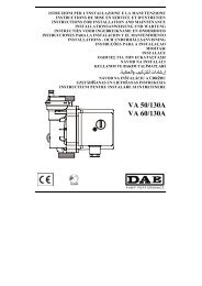
15 deutsch<br />
5.7.1 Proportionaldruck-<br />
Regelung<br />
2 LED leuchten<br />
zum Beispiel:<br />
LED 3 und 4<br />
Regelkennlinie<br />
3,2...5,4 m<br />
5.7.2 Konstantdruck-<br />
Regelung<br />
5.7.3 Konstante Drehzahl<br />
5.7 Anzeige der verschiedenen Regelkennlinien zu <strong>AC</strong> <strong>80</strong><br />
6<br />
5<br />
4<br />
3<br />
2<br />
1<br />
6<br />
5<br />
4<br />
3<br />
2<br />
1<br />
6<br />
5<br />
4<br />
3<br />
2<br />
1<br />
8,0<br />
H<br />
[m]<br />
1)<br />
7,2m<br />
4,7<br />
3,7<br />
2,6<br />
1,5<br />
1,0<br />
0<br />
1) Leistungsbegrenzung<br />
1) Leistungsbegrenzung<br />
H<br />
[m]<br />
8,0<br />
5,9<br />
4,7<br />
3,5<br />
2,3<br />
1)<br />
1,0<br />
0<br />
1) Leistungsbegrenzung<br />
1) Leistungsbegrenzung<br />
100<br />
H % 1)<br />
85<br />
<strong>65</strong><br />
45<br />
25<br />
15<br />
0<br />
1) Leistungsbegrenzung<br />
1) Leistungsbegrenzung<br />
6,0m<br />
4,7m<br />
3,3m<br />
2,1m<br />
V<br />
V<br />
V<br />
960956_01<br />
960957_01<br />
961033_00
16<br />
deutsch<br />
6. Inbetriebnahme/Betriebskontrolle<br />
6.1 Allgemeines<br />
Anlage ohne Pumpe gründlich spülen. Siehe Abschnitt 4.<br />
Die Anlage sachgemäss füllen und entlüften.<br />
Die Pumpe nur bei gefüllter Anlage in Betrieb nehmen.<br />
Versorgungsspannung einschalten.<br />
6.2 Entlüften<br />
Das Entlüften der Pumpe, speziell der Motorraum, erfolgt<br />
nach kurzer Betriebsdauer selbsttätig. Kurzzeitiger (max. 2 min)<br />
Trockenlauf schadet der Pumpe nicht.<br />
Es besteht Verbrühungsgefahr<br />
6.3 Betriebskontrolle<br />
Es muss immer eine LED aus Bereich A2 leuchten.<br />
Siehe Abschnitt 5.4.1.<br />
6.4 Deblockieren<br />
Nicht notwendig. Motor startet mit hohem Anzugsmoment,<br />
siehe Abschnitt 8.<br />
7. Wartung, Service<br />
Vor Beginn der Wartungsarbeiten die Pumpe unbedingt<br />
ausser Betrieb nehmen, allpolig vom Netz trennen und<br />
gegen Wiedereinschalten sichern.<br />
Ausführung nur durch Fachpersonal.<br />
Betriebsanleitung beachten.<br />
Arbeiten nur im Stillstand der Anlage durchführen.<br />
Pumpe spannungslos machen.<br />
Sicherung ausschalten und Warntafel anbringen.<br />
Verbrühungsgefahr durch austretendes Medium.<br />
Verbrennungsgefahr durch heisse Oberflächen.
17<br />
deutsch<br />
8. Störungsübersicht<br />
Vor dem Entfernen des Klemmenkastendeckels und vor<br />
jeder Demontage der Pumpe die Versorgungsspannung<br />
unbedingt allpolig abschalten.<br />
Elektronik kann bis 10 Minuten nach dem Ausschalten<br />
des Stromes unter Spannung sein!<br />
Störung Ursache Behebung<br />
Pumpe läuft nicht keine Spannung am Motor Schalter und Sicherungen<br />
kontrollieren<br />
Versorgungsspannung prüfen<br />
zu niedrige Netzspannung Steuerung und Netz kontrollieren<br />
Pumpe blockiert deblockieren, siehe<br />
Kurzschluss Elektronik<br />
beim Einschalten der Pumpe falsch angeschlossen richtig anschliessen<br />
��<br />
Motor defekt Pumpe auswechseln<br />
leuchtet Fehler in Elektronik Elektronik auswechseln<br />
evtl. externe Ansteuerung (Ext.)<br />
prüfen!<br />
Überprüfen ob Zusatzmodul<br />
eingebaut!<br />
blinkt Motor blockiert Pumpe mehrmals EIN/AUS schalten.<br />
Motor ausbauen zum deblockieren:<br />
– Schieber vor und nach Pumpe<br />
schliessen.<br />
– 4 Inbusschrauben lösen<br />
Achtung:<br />
heisses Wasser kann austreten.<br />
– Motor abbauen<br />
– Am Laufrad drehen bis Welle<br />
leichtgängig dreht.<br />
– Motor einbauen und Schieber<br />
öffnen.<br />
Pumpe erzeugt Geräusche Luft in der Pumpe Mehrmaliges entlüften von Anlage<br />
bei abgestellter Pumpe.<br />
Pumpe entlüftet selbsttätig<br />
siehe Abschnitt 6.2<br />
Kavitation Systemdruck erhöhen/<br />
Temperatur vermindern<br />
siehe Abschnitt 10<br />
Pumpe zu stark kleinere Regelkennlinie einstellen<br />
siehe Abschnitt 5.4/kleinere Pumpe<br />
Heizkörper werden nicht warm Pumpe zu schwach Grössere Regelkennlinie einstellen,<br />
siehe Abschnitt 5.4<br />
stärkere Pumpe einbauen<br />
Luft in der Pumpe Entlüften der Anlage<br />
bei abgestellter Pumpe,<br />
siehe Abschnitt 6.2<br />
Technische Änderungen vorbehalten<br />
��
18<br />
B<br />
L<br />
PE<br />
A<br />
0<br />
0<br />
_<br />
0<br />
5<br />
9<br />
0<br />
6<br />
9<br />
N<br />
deutsch<br />
9. Isolationswiderstandsprüfung<br />
Eine Isolationswiderstandsprüfung darf nicht in einer Installation<br />
mit DAB-Pumpen mit aufgebauter Elektronik vorgenommen<br />
werden, da diese dadurch beschädigt werden kann.<br />
Bei einer eventuellen Prüfung muss die Pumpe elektrisch getrennt<br />
werden.<br />
1. Versorgungsspannung abschalten/unterbrechen.<br />
10 min. warten bis Spannung abgebaut ist!<br />
2. Leitungen von Klemme L, N und PE ( )<br />
entfernen.<br />
3. Klemme L und N mit einer kurzen Leitung (A)<br />
kurzschliessen.<br />
4. Zwischen Klemme L und PE<br />
mit max. 1500 V<strong>AC</strong>/DC (B) testen.<br />
Achtung: Es darf unter keinen Umständen<br />
zwischen Phase (L) und (N) getestet werden.<br />
Max. zulässiger Ableitstrom < 20mA.<br />
5. Prüfgerät (B) wegnehmen<br />
6. Die kurze Leitung (A) zwischen Klemme L und N entfernen<br />
7. Leitungen L, N und PE ( ) anschliessen.<br />
8. Versorgungsspannung einschalten.
19 deutsch<br />
10. Technische Daten<br />
Versorgungsspannung: 1×230-240 V +6/-10%, 50/60 Hz<br />
Motorschutz: Ein externer Motorschutz ist nicht erforderlich<br />
Schutzart: IP 44<br />
Wicklungsklasse: Isolationsklasse F<br />
Temperaturklasse: TF <strong>110</strong><br />
Umgebungstemperatur: max. 40 °C<br />
Medientemperatur: +2 °C bis 95 °C, kurzeitig1) <strong>110</strong> °C<br />
Zur Vermeidung von Kondenswasserbildung im Klemmenkasten<br />
und im Stator muss die Medientemperatur immer höher sein<br />
als die Umgebungstemperatur.<br />
Erforderlicher Betriebsdruck<br />
bei 500m über Meer:<br />
Umgebungstemperatur Medientemperatur<br />
°C Min. °C Max. °C Max. °C 1)<br />
0 2 95 <strong>110</strong><br />
10 10 95 <strong>110</strong><br />
20 20 95 <strong>110</strong><br />
30 30 95 <strong>110</strong><br />
35 35 90 100<br />
40 40 70 100<br />
1) kurzzeitig, ca. 30 min<br />
bis 75 °C Wassertemperatur 0,10 bar<br />
bei 90 °C Wassertemperatur 0,45 bar<br />
bei <strong>110</strong> °C Wassertemperatur 1,20 bar<br />
Max. Systemdruck: 10 bar<br />
Geräusch: Schalldruckpegel liegt unter 54 dB(A)<br />
Ableitstrom: Das Netzfilter der Pumpe verursacht während des Betriebs<br />
einen Ableitstrom zur Masse (Erde) kleiner 3.5 mA<br />
11. Entsorgung<br />
Dieses Produkt, sowie spezielle Teile der Elektronik (bleifrei),<br />
müssen umweltgerecht entsorgt werden.
20<br />
français<br />
Sommaire<br />
1. Consignes de sécurité page 21<br />
1.1 Généralités 21<br />
1.2 Symboles de sécurité utilisés dans la présente notice 21<br />
1.3 Qualification et formation du personnel 21<br />
1.4 Risques et dangers en cas de non observation<br />
des consignes de sécurité 21<br />
1.5 Observation des règles de sécurité 22<br />
1.6 Consignes de sécurité à l’intention<br />
de l’utilisateur/de l’opérateur 22<br />
1.7 Consignes de sécurité relatives au montage,<br />
à l’entretien et à la révision 22<br />
1.8 Modifications et pièces de rechange 22<br />
1.9 Conformité d’utilisation 22<br />
2. Transport et stockage 22<br />
3. But d’utilisation 23<br />
3.1 Fluide transporté 23<br />
3.2 Température et pression de service 23<br />
4. Montage 23<br />
4.1 Rinçage de l’installation de chauffage 23<br />
4.2 Antigel 23<br />
4.3 Montage 23<br />
4.4 Position de montage 24<br />
4.5 Clapet de retenue 24<br />
4.6 Pression minimale 25<br />
5. Raccordement électrique 25<br />
5.1 Bornes de raccordement 26<br />
5.2 Schéma de raccordement en exécution standard 27<br />
5.3 Limitation de puissance, vitesse minimale 27<br />
5.4 Modules supplémentaires 28<br />
5.4.1 Schéma de raccordement du module de commande (option) 28<br />
5.4.2 Schéma de raccordement du module de signalisation (option) 28<br />
5.4.3 Schéma de raccordement de commande de pompes jumelées 28<br />
5.5 Autres réglages 29<br />
5.5.1 Réglage du mode de régulation (A1) 29<br />
5.5.2 Réglage de la hauteur de refoulement (A2) 30<br />
5.5.3 Autres symboles lumineux (A3) 30<br />
5.6 Réglages d’usine de la pompe 30<br />
5.7 Affichage des diverses caractéristiques<br />
de régulation pour <strong>AC</strong> <strong>80</strong> 31<br />
5.7.1 Régulation à pression proportionnelle 31<br />
5.7.2 Régulation à pression constante 31<br />
5.7.3 Vitesse constante 31<br />
6. Mise en service/contrôle de fonctionnement 32<br />
6.1 Généralités 32<br />
6.2 Purge d’air 32<br />
6.3 Contrôle de fonctionnement 32<br />
6.4 Déblocage 32<br />
7. Entretien, service 32<br />
8. Résumé des dérangements 33<br />
9. Essai de la résistance d’isolement 34<br />
10. Caractéristiques techniques 35<br />
11. Elimination 35
21<br />
français<br />
1. Consignes de sécurité<br />
1.1 Généralités<br />
La présente notice de montage et d’utilisation contient des<br />
instructions importantes pour l’installation, l’utilisation et<br />
l’entretien. Avant le montage et la mise en service le monteur et<br />
l’opérateur/l’utilisateur doivent donc absolument la lire soigneusement.<br />
De manière à avoir toujours cette notice à portée de<br />
main, veuillez la ranger à proximité immédiate de l’appareil.<br />
Observer non seulement les consignes générales de sécurité<br />
mentionnées dans le présent chapitre «Consignes de sécurité»,<br />
mais aussi celles données aux chapitres suivants.<br />
1.2 Symboles de sécurité utilisés dans la présente notice<br />
Attention<br />
Les consignes de sécurité, dont la non observation<br />
met en danger les personnes, sont<br />
précédées du symbole “danger!”<br />
selon DIN 4844-W9.<br />
Symbole de mise en garde contre les risques de<br />
nature électrique (symbole selon DIN 4844-W8)<br />
Symbole accompagnant les consignes de<br />
sécurité dont la non observation présente des<br />
risques pour l’appareil et ses fonctions.<br />
Les indications apposées sur l’appareil telles que:<br />
- flèche indiquant le sens de rotation<br />
- désignations des raccordements pour les fluides<br />
doivent être strictement observées et toujours propres afin<br />
d’être parfaitement lisibles.<br />
1.3 Qualification et formation du personnel<br />
Les personnes chargées d’installer, de faire fonctionner, d’entretenir<br />
et de réviser l’installation doivent justifier de la qualification<br />
requise pour ces différentes tâches. Domaines de<br />
responsabilité, compétences et encadrement du personnel<br />
doivent être définis de manière claire et précise par l’utilisateur.<br />
1.4 Risques et dangers en cas de non observation<br />
des consignes de sécurité<br />
La non observation des consignes de sécurité comporte des<br />
risques, non seulement pour les personnes mais aussi pour<br />
l’environnement et l’installation. De plus, elle peut entraîner la<br />
nullité des droits d’indemnisation en cas de dommages.
22<br />
français<br />
La non observation des consignes de sécurité peut par exemple<br />
provoquer:<br />
- Panne de fonction importante dans l’installation<br />
- l’échec des méthodes d’entretien et de maintenance prescrites<br />
- la mise en danger des personnes par des phénomènes de<br />
nature électrique ou mécanique.<br />
1.5 Observation des règles de sécurité<br />
Les consignes de sécurité indiquées dans cette notice, les réglementations<br />
nationales de prévention contre les accidents ainsi<br />
que, le cas échéant, les consignes de sécurité internes à l’intention<br />
de l’utilisateur, doivent être rigoureusement observées.<br />
1.6 Consignes de sécurité à l’intention de l’utilisateur/<br />
de l’opérateur<br />
Tout risque de nature électrique doit être écarté. A ce sujet<br />
veuillez vous reporter par exemple aux consignes NIN<br />
(CENELEC) ainsi qu’aux consignes prescrites par votre fournisseur<br />
local en électricité.<br />
1.7 Consignes de sécurité relatives au montage, à l’entretien<br />
et à la révision<br />
Il incombe à l’utilisateur de veiller à ce que les opérations de<br />
montage, d’entretien et de révision soient effectuées par un<br />
personnel qualifié et autorisé, et ayant lu attentivement les<br />
instructions données dans la présente notice.<br />
D’une manière générale, les interventions sur l’installation ne<br />
doivent être effectuées qu’après avoir mis la dite installation à<br />
l’arrêt et hors tension.<br />
A la fin de chaque intervention, réinstaller/réactiver tous les<br />
organes de sécurité et toutes les protections.<br />
Avant de remettre l’installation en marche, observer les points<br />
indiqués au chapitre «Raccordement électrique».<br />
1.8 Modifications et pièces de rechange<br />
Toute modification ou transformation d’une pompe par l’utilisateur<br />
nécessite l’accord préalable du constructeur. Pour votre<br />
propre sécurité, utilisez uniquement des pièces de rechange de<br />
la marque, et les accessoires recommandés par le constructeur.<br />
Nous déclinons toute responsabilité en cas de dommages résultant<br />
de l’utilisation d’autres pièces ou accessoires.<br />
1.9 Conformité d’utilisation<br />
La sécurité d’utilisation des pompes livrées n’est garantie que<br />
dans le cas d’une utilisation conforme, telle que spécifiée au<br />
chapitre «But d’utilisation» de la présente notice. Les valeurs<br />
limites indiquées sur la feuille des caractéristiques techniques<br />
ne doivent en aucun cas être dépassées.<br />
2. Transport et stockage<br />
Les pompes sont expédiées de l’usine dans un emballage<br />
adéquat.
23<br />
français<br />
3. Caractéristiques, buts d’utilisation<br />
Les circulateurs DAB de la série<br />
<strong>AC</strong> <strong>65</strong>, <strong>AC</strong> <strong>80</strong>, <strong>AC</strong> <strong>110</strong><br />
possèdent un moteur à aimant permanent avec chemise spéciale et<br />
un convertisseur de fréquence intégré avec régulation<br />
à pression constante, à pression proportionnelle et à vitesse<br />
constante.<br />
La pompe est utilisée pour le transport de liquides dans des:<br />
– installations de chauffage à eau chaude<br />
– systèmes industriels fermés à circulation.<br />
– Installations d’eau potable (AW)<br />
3.1 Fluide transporté<br />
Le fluide véhiculé dans les installations de chauffage doit répondre<br />
aux exigences sur l’eau de chauffage selon VDI 2035.<br />
Mélange eau-glycol autorisé jusqu’à une proportion de 50%<br />
de glycol.<br />
Dans des installations d’eau potable, la pompe ne peut être utilisée<br />
qu’avec de l’eau d’un degré de dureté
24<br />
4.4 Position de montage<br />
Etat de livraison<br />
Raccord de câble à gauche<br />
La flèche sur le bâti<br />
de la pompe indique<br />
le sens d’écoulement.<br />
La boîte à bornes ne doit pas<br />
être dirigée vers le haut,<br />
sinon de l’eau risque<br />
d’y pénétrer facilement.<br />
Avant le montage de<br />
la pompe, la boîte à bornes<br />
peut être tournée de 90°.<br />
Il faut à cet effet dévisser<br />
les 4 vis du corps et tourner<br />
la tête du moteur dans<br />
la position admissible<br />
de la boîte à bornes.<br />
Ne pas déplacer ni endommager<br />
le joint entre<br />
le moteur et le corps<br />
de la pompe.<br />
Après la pose des vis,<br />
les serrer en croisant.<br />
Sens d’écoulement<br />
La flèche sur le corps<br />
de la pompe indique<br />
le sens d’écoulement.<br />
L’arbre doit toujours être<br />
horizontal, jamais vertical.<br />
4.5 Clapet de retenue<br />
Si un clapet de retenue est<br />
monté, la pompe doit être<br />
réglée (voir point 5.4.2)<br />
de telle sorte que la pression<br />
minimale de refoulement<br />
de la pompe dépasse<br />
en tout temps la pression<br />
de fermeture du clapet.<br />
français
25<br />
français<br />
Poser des vannes d’arrêt avant et après la pompe.<br />
On évite ainsi lors d'un éventuel remplacement de la pompe<br />
la vidange et le remplissage de l'installation.<br />
4.6 Pression minimale<br />
La pression minimale au raccord d’aspiration de la pompe à 75°C<br />
pour une lubrification sûre des paliers lisses:<br />
Les valeurs s’appliquent jusqu’à 500 m d’altitude.<br />
Supplément pour plus hautes altitudes:<br />
0,01 bar par 100 m d’augmentation d’altitude<br />
à 75 °C 0,10 bar<br />
90 °C 0,55 bar<br />
<strong>110</strong> °C 1,20 bar<br />
5. Raccordement électrique<br />
Le raccordement électrique doit être exécuté<br />
par un électricien en accord avec le fournisseur<br />
local d’énergie.<br />
Respecter les prescriptions NIN (CENELEC).<br />
Pour des températures de l’eau plus élevées (dès <strong>80</strong>°C),<br />
utiliser une conduite de raccordement résistante à la chaleur.<br />
La conduite de raccordement ne doit pas toucher le bâti<br />
de la pompe et du moteur.<br />
Observer la protection contre les égouttements d’eau<br />
et la bride de décharge de traction à l’entrée du câble<br />
dans la boîte de raccordement (presse-étoupe)!<br />
Fusible d’entrée: (Courant nominal ×1,5) max. 10 A, retardé<br />
Section du fil: max. 1,5 mm2 Le raccordement électrique doit être effectué conformément<br />
à la plaquette signalétique.<br />
Pour faciliter un remplacement ultérieur, le raccordement<br />
électrique doit être muni d’une boucle. Il faut s’assurer<br />
que les données électriques de la plaquette signalétique<br />
de la pompe concordent avec l’alimentation électrique.<br />
Remarque: Accorder une attention particulière au raccordement<br />
du conducteur de protection. Le conducteur de protection doit être<br />
plus long que le conducteur polaire (risque d'arrachement).<br />
Tension d’alimentation:<br />
1×230-240 V +6%/–10%, 50/60 Hz, PE<br />
<strong>AC</strong> <strong>65</strong> <strong>AC</strong> <strong>80</strong> <strong>AC</strong> <strong>110</strong><br />
Courant nominal Régulation 0,1…0,48 A 0,1…0,77 A 0,1…1,24 A<br />
min. 0,14 A 0,14 A 0,14 A<br />
Puissance Régulation 8...70 W 8...107 W 8...174 W<br />
min. 8...19 W 8...19 W 8...19 W
26<br />
960940_00<br />
français<br />
5.1 Bornes de raccordement<br />
Raccordement au réseau 1×230-240 V<br />
Conducteur de protection<br />
L Conducteur<br />
N Conducteur neutre<br />
1×230-240 V +6/–10%, 50/60 Hz<br />
En cas d’emploi de disjoncteur de protection à courant de défaut<br />
(FI), il faut utiliser une exécution sensible au courant positif,<br />
qui tient compte lors de l’enclenchement du réseau de l’impulsion<br />
du courant de charge vers la terre et qui convient pour le courant<br />
de fuite de la pompe inférieur à 3.5 mA.<br />
Les disjoncteurs FI doivent être marqués<br />
du symbole indiqué.<br />
Remarque:<br />
Avant chaque intervention dans la boîte à bornes,<br />
la tension d’alimentation doit être coupée.<br />
Ouvrir la boîte à bornes<br />
Vis: Torx 20<br />
Relever le couvercle<br />
En cas d’erreur de raccordement ou de tension<br />
erronée, le moteur risque d’être endommagé!<br />
Attention lors de l’ouverture du couvercle<br />
de l’électronique!<br />
L’électronique peut rester sous tension jusqu’à<br />
10 minutes après le déclenchement du courant.<br />
Etiquette dans le couvercle<br />
avec type, version, date de production
27 français<br />
Schéma de raccordement 1)<br />
51-54<br />
Message de dérangement<br />
(contact de fermeture<br />
sans potentiel fermé en cas<br />
de dérangement), charge<br />
de contact max. 250V~, 1A<br />
51-52<br />
Message de dérangement<br />
(contact d’ouverture<br />
sans potentiel ouvert<br />
en cas de dérangement)<br />
Charge du contact<br />
max. 250 V~, 1A<br />
Switch<br />
OFF<br />
ON<br />
5.2 Schéma de raccordement en exécution standard<br />
54 52 51<br />
max. 250V<br />
1A<br />
N L<br />
Alimentation<br />
~1×230 V<br />
Fusible d’entrée<br />
10 A<br />
Switch<br />
Switch ON OFF<br />
1 Limitation de puissance Limitation de puissance<br />
EN (ON) HORS (OFF)<br />
2 Bornes 51, 52, 54 Bornes 51, 52, 54<br />
1) Message de marche Signalisation<br />
de dérangement<br />
Remarques sur les réglages Switch<br />
1) La limitation de puissance Pred est réglée en série à <strong>80</strong>%<br />
de Pmax afin d’éviter des bruits dus à un trop fort débit<br />
V [m 3 /h] de la pompe.<br />
Au besoin, le réglage peut être modifié pour le débit max.<br />
de la pompe.<br />
5.3 Limitation de puissance, vitesse minimale:<br />
La pompe peut être réglée à une vitesse minimale (min.).<br />
Vitesse minimale (min )<br />
Limitation de puissance (P red)<br />
0<br />
0<br />
_<br />
1<br />
4<br />
9<br />
0<br />
6<br />
9<br />
= Etat de livraison
28 français<br />
81-82 Multitherm/PWM<br />
Entrée pour prescription<br />
externe de vitesse<br />
71-72 Entrée analogique<br />
0…10 V ou 0…20 mA<br />
pour prescription<br />
externe de vitesse<br />
10-11 Contact de commande<br />
pour déclenchement<br />
externe de la pompe<br />
91-92 Double pompe<br />
10-11 Contact de commande<br />
pour déclenchement<br />
externe de la pompe<br />
10-13 Contact de commande<br />
pour enclenchement et<br />
déclenchement externes<br />
de la vitesse minimale<br />
91-92 Double pompe<br />
61-64 Message de marche<br />
ou de disponibilité<br />
(contact de fermeture)<br />
61-62 Message de marche<br />
ou de disponibilité<br />
(contact d'ouverture)<br />
Fonction seulement<br />
avec module<br />
de commande<br />
ou de signalisation<br />
91-92 Double pompe<br />
Détails techniques<br />
des modules<br />
supplémentaires,<br />
voir «Instructions<br />
de service du module<br />
supplémentaire»<br />
5.4 Modules supplémentaires<br />
5.4.1 Schéma de raccordement du module de commande (option)<br />
961177_00<br />
81 82 71 72 11 10 91 92<br />
5.4.2 Schéma de raccordement du module de signalisation (option)<br />
961178_00<br />
13 11 10 91 92 64 62<br />
61<br />
5.4.3 Schéma de raccordement de commande de pompes jumelées<br />
91 92 91 92<br />
N L N L<br />
961175_00
29 français<br />
Cycle du mode<br />
de régulation<br />
LED<br />
V .<br />
5.5 Autres réglages<br />
A) Clavier de commande<br />
B) Plaquette de la marque<br />
Il y a un risque de brûlure!<br />
Pour de hautes températures du fluide, la pompe<br />
peut devenir si chaude que seules les touches<br />
de commande peuvent être touchées.<br />
A1) Touche de commande<br />
pour le choix du mode de régulation et de la signalisation (LED)<br />
voir paragraphe 5.4.1<br />
A2) Touche de commande pour le réglage (hauteur de refoulement)<br />
avec symboles lumineux (LED) pour afficher la hauteur<br />
et le débit de refoulement<br />
Voir paragraphe 5.4.2<br />
A3) Symbole lumineux de dérangement, commande externe (Ext)<br />
Voir paragraphe 5.4.3<br />
5.5.1 Réglage du mode de régulation (A1)<br />
S<br />
Aut.<br />
Attention<br />
Touche de commande «S»<br />
Pression proportionnelle<br />
recommandée dans la plupart des systèmes<br />
à deux tubes, spécialement avec des radiateurs.<br />
Pression constante, peut être judicieuse<br />
dans les installations suivantes: ancien chauffage<br />
par gravité avec très basses pertes de charge;<br />
pompes de circuit primaire dans des installations<br />
avec basses pertes de charge;<br />
chauffages par le sol avec vannes thermostatiques<br />
et chauffages monotube.<br />
Vitesse constante<br />
La pompe tourne à vitesse constante<br />
entre 1400 et 3500 1 /min<br />
Vitesse minimale automatique<br />
Si la température de départ diminue de 10 à 15 °C,<br />
la puissance de la pompe sera réduite sur (min )<br />
après 1 à 2 h environ.<br />
Si la température de départ augmente de 10 °C,<br />
il y a commutation immédiate sur mode régulation.<br />
LED allumée: présélectionné<br />
LED clignotante: la pompe est en mode vitesse minimale<br />
Vitesse minimale automatique ne pas enclencher<br />
dans les chauffages à bois et à gaz, les chauffe-eau,<br />
la charge d’accumulateurs, les conduites à distance,<br />
les pompes à chaleur, etc.
30 français<br />
▲ ▲<br />
6 8,0 m 8,0 m<br />
5 4,7…7,2 m 5,9 m<br />
4 3,7…6,0 m 4,7 m<br />
3 2,6…4,7 m 3,5 m<br />
2 1,5…3,3 m 2,3 m<br />
1 1,0…2,1 m 1,0 m<br />
6<br />
5<br />
4<br />
3<br />
2<br />
1<br />
H<br />
5.5.2 Réglage de la hauteur de refoulement (A2)<br />
La valeur de consigne de la pompe peut se régler en pressant<br />
sur la touche ou<br />
par ex. LED 3 allumée (jaune)<br />
LED 3 et 4 allumées:<br />
caractéristique entre 3 et 4<br />
Indication sur la plaquette de la marque, par ex. <strong>AC</strong> <strong>80</strong><br />
Caractéristique de régulation réglée, voir plaquette de la marque (B)<br />
Caractéristique «3» Vmin H = 2,6 m<br />
Vmax H = 4,7 m<br />
Attention<br />
Si certains radiateurs ne chauffent pas assez,<br />
régler la caractéristique immédiatement<br />
supérieure.<br />
Indications supplémentaires au paragraphe 5.6.<br />
.<br />
Diodes luminescentes «LED V»<br />
Affichage . (jaune) du débit actuel<br />
V = 25, 50, 75, 100%<br />
5.5.3 Autres symboles lumineux (A3)<br />
��<br />
��� ���<br />
Ext<br />
Dérangement<br />
S’allume en rouge / clignotante rouge<br />
Quittance de dérangement:<br />
les messages de dérangement peuvent se quittancer<br />
en appuyant brièvement sur une touche quelconque.<br />
Commande externe<br />
S’allume en jaune<br />
– Modules supplémentaires<br />
dans le coffret de raccordement<br />
– Commande à distance<br />
5.6 Réglages d’usine de la pompe<br />
1<br />
Switch 1<br />
ON<br />
Pression proportionnelle<br />
LED allumée en jaune<br />
Caractéristique de régulation réglée sur 1<br />
LED allumée en jaune<br />
Limitation de puissance EN<br />
(paragraphe 5.2)
31 français<br />
5.7.1 Régulation à pression<br />
proportionnelle<br />
2 LED allumées:<br />
par exemple:<br />
LED 3 et 4<br />
courbes caractéristique<br />
3,2...5,4 m<br />
5.7.2 Régulation à pression<br />
constante<br />
5.7.3 Vitesse constante<br />
5.7 Affichage des diverses caractéristiques de régulation pour <strong>AC</strong> <strong>80</strong><br />
6<br />
5<br />
4<br />
3<br />
2<br />
1<br />
6<br />
5<br />
4<br />
3<br />
2<br />
1<br />
6<br />
5<br />
4<br />
3<br />
2<br />
1<br />
8,0<br />
H<br />
[m]<br />
1)<br />
7,2m<br />
4,7<br />
3,7<br />
2,6<br />
1,5<br />
1,0<br />
0<br />
1) Limitation de puissance<br />
1) Leistungsbegrenzung<br />
H<br />
[m]<br />
8,0<br />
5,9<br />
4,7<br />
3,5<br />
2,3<br />
1)<br />
1,0<br />
0<br />
1) Limitation de puissance<br />
1) Leistungsbegrenzung<br />
100<br />
H % 1)<br />
85<br />
<strong>65</strong><br />
45<br />
25<br />
15<br />
0<br />
1) Limitation de puissance<br />
1) Leistungsbegrenzung<br />
6,0m<br />
4,7m<br />
3,3m<br />
2,1m<br />
V<br />
V<br />
V<br />
960956_01<br />
960957_01<br />
961033_00
32<br />
français<br />
6. Mise en service/contrôle de fonctionnement<br />
6.1 Généralités<br />
Rincer à fond l’installation sans la pompe. Voir paragraphe 4.<br />
Remplir l’installation dans les règles et la purger d’air.<br />
Ne mettre la pompe en marche que si l’installation est remplie.<br />
Enclencher la tension d’alimentation.<br />
6.2 Purge d’air<br />
La purge d'air, en particulier l’espace du moteur, se fait<br />
d’elle-même après une courte durée de fonctionnement.<br />
Une brève marche à sec (max. 2 min) n’endommage pas<br />
la pompe.<br />
Il y a un risque de brûlure!<br />
6.3 Contrôle de fonctionnement<br />
Une LED du domaine A2 doit toujours être allumée.<br />
Voir paragraphe 5.4.1.<br />
6.4 Déblocage<br />
Pas nécessaire. Le moteur démarrage avec un fort couple,<br />
voir paragraphe 8.<br />
7. Entretien, service<br />
Avant de commencer les travaux d’entretien,<br />
il faut absolument mettre la pompe hors service,<br />
la séparer du réseau sur tous les pôles<br />
et l’assurer contre un enclenchement involontaire.<br />
Exécution uniquement par le personnel spécialisé.<br />
Respecter les instructions de service.<br />
N’exécuter le travail que sur l’installation au repos.<br />
Mettre la pompe hors tension.<br />
Déclencher le disjoncteur<br />
et apposer un panneau d’avertissement.<br />
Risque de brûlure par le fluide qui s’échappe.<br />
Risque de brûlure par les surfaces chaudes
33<br />
français<br />
8. Résumé des dérangements<br />
Avant d’enlever le couvercle de la boîte à bornes et avant<br />
tout démontage de la pompe, déclencher absolument<br />
la tension d’alimentation sur tous les pôles.<br />
L’électronique peut se trouver sous tension jusqu’à<br />
10 minutes après le déclenchement du courant!<br />
Dérangement Cause Réparation<br />
La pompe ne tourne pas Pas de tension sur le moteur Contrôler les interrupteurs<br />
et fusibles<br />
Vérifier la tension d’alimentation<br />
Tension du réseau trop basse Contrôler la tension et le réseau<br />
Pompe bloquée Débloquer, voir<br />
Court-circuit à l’enclenchement Electronique<br />
de la pompe mal connectée Raccorder correctement<br />
Moteur défectueux Remplacer la pompe<br />
��<br />
s’allume Défaut dans l’électronique Remplacer l’électronique,<br />
vérifier év. la commande externe<br />
(Ext)!<br />
Vérifier si le module<br />
supplémentaire est raccordé!<br />
clignotante Moteur bloqué Enclencher et déclencher plusieurs<br />
fois la pompe<br />
Démonter le moteur pour débloquer:<br />
– Fermer les vannes avant<br />
et après la pompe<br />
– Démonter le moteur; dévisser<br />
4 vis à 6 pans creux.<br />
Attention:<br />
de l’eau chaude peut sortir.<br />
– Démonter le moteur<br />
– Tourner la roue jusqu’à ce que<br />
l’arbre tourne librement.<br />
– Monter le moteur<br />
et ouvrir les vannes.<br />
La pompe fait du bruit Air dans la pompe Purger plusieurs fois l’installation<br />
avec la pompe arrêtée.<br />
La pompe se purge elle-même.<br />
Voir paragraphes 6.2<br />
Cavitation Augmenter la pression du système/<br />
réduire la température,<br />
voir paragraphe 10<br />
Pompe trop puissante Régler une caractéristique<br />
plus basse, voir paragraphe 5.4<br />
pompe plus petite<br />
Les radiateurs ne chauffent pas Pompe trop faible Régler une caractéristique<br />
plus forte, voir paragraphe 5.4/<br />
monter une pompe plus forte<br />
Air dans la pompe Purger l’installation<br />
avec la pompe arrêtée,<br />
voir paragraphe 6.2<br />
Sous réserve de modifications techniques<br />
��
34<br />
B<br />
L<br />
PE<br />
A<br />
0<br />
0<br />
_<br />
0<br />
5<br />
9<br />
0<br />
6<br />
9<br />
N<br />
français<br />
9. Essai de la résistance d’isolement<br />
Il ne faut pas procéder à un essai de la résistance d’isolement<br />
dans une installation comprenant des pompes DAB avec<br />
électronique montée, car celles-ci risquent d’être endommagées.<br />
Lors d’un essai éventuel, la pompe doit être séparée<br />
électriquement.<br />
1. Déclencher/interrompre la tension d’alimentation.<br />
Attendre 10 min jusqu’à ce que la tension se soit annulée.<br />
2. Enlever les lignes des bornes L, N et PE ( )<br />
3. Court-circuiter les bornes L et N avec une courte ligne (A)<br />
4. Tester entre les bornes L et PE avec au max. 1500 V<strong>AC</strong>/DC (B)<br />
Attention: Il ne faut tester en aucun cas<br />
entre les bornes L et N.<br />
Courant de fuite max. admissible < 20 mA.<br />
5. Enlever l’instrument d’essai (B).<br />
6. Enlever la courte ligne (A) entre les bornes L et N.<br />
7. Raccorder les lignes L, N et PE ( )<br />
8. Enclencher la tension d’alimentation.
35 français<br />
10. Caractéristiques techniques<br />
Tension d’alimentation: 1×230-240 V +6/-10%, 50/60 Hz<br />
Protection du moteur: Une protection externe du moteur n’est pas nécessaire<br />
Mode de protection: IP 44<br />
Classe d’enroulement: Classe d’isolation F<br />
Classe de température: TF <strong>110</strong><br />
Température ambiante: max. 40 °C<br />
Température du liquide: +2 °C jusqu’à 95 °C, brièvement1) <strong>110</strong> °C<br />
Pour éviter une condensation d’eau dans la boîte à bornes<br />
et dans le stator, la température du fluide doit toujours être<br />
supérieure à la température ambiante.<br />
Pression minimale<br />
à 500m d’altitude:<br />
Température ambiante Température du liquide<br />
°C Min. °C Max. °C Max. °C 1)<br />
0 2 95 <strong>110</strong><br />
10 10 95 <strong>110</strong><br />
20 20 95 <strong>110</strong><br />
30 30 95 <strong>110</strong><br />
35 35 90 100<br />
40 40 70 100<br />
1) brièvement, env. 30 min<br />
jusqu’à une température de l’eau de 75 °C 0,10 bar<br />
à une température de l’eau de 90 °C 0,45 bar<br />
à une température de l’eau de <strong>110</strong> °C 1,20 bar<br />
Pression de service nécessaire: 10 bar<br />
Bruit: Niveau de pression acoustique inférieur à 54 dB(A)<br />
Courant de fuite: Le filtre de réseau de la pompe cause en fonctionnement<br />
un courant de fuite à la masse (terre) inférieur à 3,5 mA<br />
11. Elimination<br />
Ce produit, ainsi que les pièces spéciales de l'électronique<br />
(sans plomb), doivent être éliminés conformément aux lois<br />
sur la protection de l'environnement.
36<br />
italiano<br />
Indice<br />
1. Avvertenze di sicurezza Pagina 37<br />
1.1 Generalità 37<br />
1.2 Contrassegno delle avvertenze 37<br />
1.3 Qualifica e addestramento del personale 37<br />
1.4 Pericoli in caso di inosservanza<br />
della avvertenze di sicurezza 37<br />
1.5 Lavoro in conformità alle avvertenze<br />
e norme di sicurezza 38<br />
1.6 Avvertenze di sicurezza per l’esercente e l’operatore 38<br />
1.7 Avvertenze di sicurezza per i lavori di montaggio,<br />
manutenzione e ispezione 38<br />
1.8 Modifiche e fabbricazione di parti<br />
di ricambio senza autorizzazione 38<br />
1.9 Modalità d’uso non consentite 38<br />
2. Trasporto e magazzinaggio 38<br />
3. Caratteristiche, campo d’applicazione 39<br />
3.1 Liquido convogliato 39<br />
3.2 Temperatura di esercizio/Pressione di esercizio 39<br />
4. Montaggio 39<br />
4.1 Lavaggio dell’impianto di riscaldamento 39<br />
4.2 Antigelo 39<br />
4.3 Installazione 39<br />
4.4 Posizione di montaggio 40<br />
4.5 Valvola di non ritorno 40<br />
4.6 Pressione minima 41<br />
5. Allacciamento elettrico 41<br />
5.1 Morsetti 42<br />
5.2 Schema di collegamento della versione standard 43<br />
5.3 Limitatore di potenza, regime minimo 43<br />
5.4 Moduli aggiuntivi 44<br />
5.4.1 Schema di collegamento del modulo di comando (optional) 44<br />
5.4.2 Schema di collegamento del modulo di segnale (optional) 44<br />
5.4.3 Schema di collegamento del comando della pompa gemella 44<br />
5.5 Altre impostazioni 45<br />
5.5.1 Impostazione del tipo di regolazione (A1) 45<br />
5.5.2 Impostazione della prevalenza (A2 46<br />
5.5.3 Altro simbolo luminoso (A3) 46<br />
5.6 Impostazione da stabilimento della pompa 46<br />
5.7 Visualizzazione delle varie caratteristiche<br />
di regolazione per <strong>AC</strong> <strong>80</strong> 47<br />
5.7.1 Regolazione della pressione proporzionale 47<br />
5.7.2 Regolazione della pressione costante 47<br />
5.7.3 Numero di giri costante 47<br />
6. Messa in funzione/Controllo del funzionamento 48<br />
6.1 Generalità 48<br />
6.2 Sfiato 48<br />
6.3 Controllo del funzionamento 48<br />
6.4 Sbloccaggio 48<br />
7. Manutenzione, assistenza 48<br />
8. Panoramica delle anomalie 49<br />
9. Test della resistenza di isolamento 50<br />
10. Dati tecnici 51<br />
11. Smaltimento 51
37<br />
italiano<br />
1. Avvertenze di sicurezza<br />
1.1 Generalità<br />
Queste istruzioni per il montaggio e l’uso contengono delle<br />
avvertenze fondamentali di cui va tenuto conto ai fini dell’<br />
installazione, dell’uso e della manutenzione. Esse debbono<br />
quindi essere assolutamente lette dal montatore e dal personale<br />
specializzato, nonché dall’esercente responsabile, prima del<br />
montaggio e della messa in funzione. Dovranno inoltre restare<br />
sempre a disposizione nelle vicinanze dell’impianto.<br />
Non solo dovranno essere rispettate le avvertenze di sicurezza<br />
generali, riportate in questo capitolo e intitolate «Avvertenze di<br />
sicurezza», ma anche le avvertenze di sicurezza particolari<br />
riportate negli altri capitoli.<br />
1.2 Contrassegno delle avvertenze<br />
Attenzione<br />
Le avvertenze di sicurezza contenute in queste<br />
istruzioni per il montaggio e l’uso, tali da<br />
comportare pericolo per la persona in caso di<br />
inosservanza, sono contrassegnate espressamente<br />
con il simbolo di pericolo generale<br />
«Simbolo di sicurezza secondo DIN 4844-W9».<br />
Questo simbolo avverte dalla presenza di tensione<br />
elettrica pericolosa.<br />
«Simbolo di sicurezza secondo DIN 4844-W8»<br />
Questo simbolo si trova nelle avvertenze di<br />
sicurezza la cui inosservanza può comportare dei<br />
pericoli per la macchina e le sue funzioni.<br />
Le avvertenze applicate direttamente sull’impianto, come ad<br />
esempio:<br />
- freccia per il senso di rotazione<br />
- contrassegno per raccordi fluidi<br />
debbono essere assolutamente rispettate e mantenute in stato<br />
perfettamente leggibile.<br />
1.3 Qualifica e addestramento del personale<br />
Il personale responsabile per il montaggio, il comando, la<br />
manutenzione e l’ispezione deve dimostrare di possedere la<br />
qualifica adatta per svolgere questi lavori. L’ambito di responsabilità,<br />
le competenze e i compiti di sorveglianza da parte del<br />
personale debbono essere stabiliti chiaramente da parte dell’<br />
esercente.<br />
1.4 Pericoli in caso di inosservanza delle avvertenze<br />
di sicurezza<br />
L’inosservanza delle avvertenze di sicurezza può causare<br />
pericolo alle persone, all’ambiente e all’impianto. L’inosservanza<br />
delle avvertenze di sicurezza può condurre alla perdita di tutti<br />
i diritti al risarcimento di eventuali danni.
38<br />
italiano<br />
In particolare l’inosservanza può provocare, ad esempio,<br />
i seguenti pericoli:<br />
- guasti tali da pregiudicare funzioni importanti per l’impianto<br />
- non funzionamento di metodi prescritti per la manutenzione<br />
- esposizione a pericolo di persone a causa di azioni elettriche<br />
e meccaniche<br />
1.5 Lavoro in conformità alle avvertenze e norme di sicurezza<br />
Debbono essere osservate: le avvertenze di sicurezza riportate<br />
in queste istruzioni per il montaggio e l’uso, le norme nazionali<br />
esistenti riguardo la prevenzione degli infortuni, eventuali<br />
norme interne sul lavoro, l’uso e la sicurezza stabilite dall’<br />
esercente.<br />
1.6 Avvertenze di sicurezza per l’esercente e l’operatore<br />
Deve essere prevenuto qualsiasi pericolo causato da energia<br />
elettrica (per maggiori particolari vedi ad esempio le norme<br />
della NIN (CENELEC) e delle aziende elettriche locali).<br />
1.7 Avvertenze di sicurezza per i lavori di montaggio,<br />
manutenzione e ispezione.<br />
L’esercente dovrà provvedere a far eseguire tutti i lavori di<br />
montaggio, manutenzione e ispezione da personale autorizzato<br />
e qualificato; tale personale dovrà informarsi adeguatamente<br />
tramite approfondita lettura delle istruzioni di montaggio e di<br />
uso.<br />
Fondamentalmente, i lavori sull’impianto dovranno essere<br />
compiuti solo in stato di macchina ferma e non sotto tensione.<br />
Immediatamente dopo la conclusione dei lavori, si dovranno<br />
nuovamente applicare o mettere in funzione tutte le attrezzature<br />
di sicurezza e di protezione.<br />
Prima della rimessa in funzione si dovrà tener conto dei punti<br />
elencati nel capitolo «Allacciamento elettrico».<br />
1.8 Modifiche e fabbricazione di parti di ricambio<br />
senza autorizzazione<br />
Qualsiasi cambiamento o modifica delle pompe è consentito<br />
solo previa autorizzazione da parte del fabbricante. Le parti di<br />
ricambio originali e gli accessori autorizzati dal fabbricante sono<br />
importanti ai fini della sicurezza.<br />
L’uso di parti estranee può condurre all’annullamento di ogni<br />
responsabilità per le conseguenze derivanti.<br />
1.9 Modalità d’uso non consentite<br />
La sicurezza di funzionamento delle pompe fornite è garantita<br />
solo a condizione che esse vengano usate in conformità<br />
alle intenzioni del costruttore, come da capitolo «Campo<br />
d’applicazione» delle istruzioni di montaggio ed uso. I valori<br />
limite indicati nei dati tecnici non debbono essere in alcun caso<br />
superati.<br />
2. Trasporto/Magazzinaggio<br />
Le pompe lasciano lo stabilimento del costruttore inserite<br />
in un apposito imballaggio.
39<br />
italiano<br />
3. Caratteristiche, campo d’applicazione<br />
Le pompe di circolazione DAB delle serie<br />
<strong>AC</strong> <strong>65</strong>, <strong>AC</strong> <strong>80</strong>, <strong>AC</strong> <strong>110</strong><br />
comprendono un motore a magnete permanente con collimatore<br />
e un convertitore di frequenza integrato con regolazione della<br />
pressione costante, della pressione proporzionale e regime costante.<br />
La pompa viene utilizzata per la circolazione di liquidi in:<br />
– impianti di riscaldamento con acqua calda<br />
– sistemi di circolazione chiusi per uso industriale<br />
– Impianti di acqua potabile (AW)<br />
3.1 Liquido convogliato<br />
Negli impianti di riscaldamento il liquido convogliato deve<br />
corrispondere ai requisiti dell’acqua calda secondo la norma<br />
VDI 2035. Le miscele di acqua e glicole sono ammesse fino<br />
a una percentuale di glicole del 50%.<br />
Negli impianti dell’acqua potabile la pompa deve essere usata<br />
con acqua con un grado di durezza
40<br />
4.4 Posizione di montaggio<br />
Stato alla consegna<br />
Cablaggio a sinistra<br />
La freccia riportata<br />
sul corpo della pompa indica<br />
la direzione di flusso.<br />
La morsettiera non deve<br />
essere rivolta verso l’alto,<br />
per evitare che l’acqua possa<br />
penetrare facilmente al suo<br />
interno.<br />
Prima del montaggio della<br />
pompa la morsettiera può<br />
essere ruotata di 90°.<br />
In questo caso, svitare<br />
le 4 viti del corpo e ruotare<br />
la testa del motore nella<br />
posizione ammessa dalla<br />
morsettiera<br />
Evitare di spostare o di<br />
danneggiare la guarnizione<br />
tra il motore e il corpo della<br />
pompa.<br />
Quando si riposizionano<br />
le viti, serrarle in modo<br />
incrociato.<br />
La freccia riportata sul<br />
corpo della pompa indica<br />
la direzione del flusso.<br />
L’albero deve sempre essere<br />
in posizione orizzontale,<br />
mai verticale.<br />
4.5 Valvola di non ritorno<br />
Se è installata una valvola<br />
di non ritorno, la pompa deve<br />
essere regolata (fare riferimento<br />
al punto 6.4) in modo<br />
tale che la pressione di<br />
mandata minima della pompa<br />
superi sempre la pressione di<br />
chiusura della valvola.<br />
italiano
41<br />
italiano<br />
Installare una saracinesca a monte e a valle della pompa.<br />
In questo modo, in caso di una possibile sostituzione della pompa,<br />
si evita lo svuotamento e il successivo riempimento dell’impianto.<br />
4.6 Pressione minima<br />
Qui sotto è riportata la pressione minima nel tronchetto<br />
di aspirazione della pompa a 75 °C per una lubrificazione sicura<br />
dei cuscinetti radenti:<br />
I valori sono validi fino a 500 m sul livello del mare.<br />
Maggiorazione per altitudini superiori:<br />
0,01 bar per ogni 100 m di aumento dell’altitudine<br />
con 75 °C 0,10 bar<br />
90 °C 0,55 bar<br />
<strong>110</strong> °C 1,20 bar<br />
5. Allacciamento elettrico<br />
L’allacciamento elettrico deve essere eseguito<br />
da un tecnico specialista in conformità a quanto<br />
previsto dalle aziende di approvvigionamento<br />
di energia del posto.<br />
Osservare le norme NIN (CENELEC).<br />
In caso di temperature dell’acqua elevate (a partire da <strong>80</strong> °C),<br />
utilizzare una linea di allacciamento in grado di resistere<br />
alle temperature previste.<br />
La linea di allacciamento non deve toccare né le tubazioni,<br />
né il corpo della pompa e del motore.<br />
Quando si effettua il cablaggio nelle cassette terminali,<br />
osservare la protezione contro lo stillicidio e lo scarico<br />
della trazione (premitreccia)!<br />
Fusibile preliminare: (Corrente nominale ×1,5) max. 10 A, ritardato<br />
Sezione del filo: max. 1,5 mm2 L’allacciamento elettrico deve essere eseguito rispettando i dati<br />
riportati sull’apposita targhetta.<br />
Per agevolare la sostituzione successiva, l’allacciamento elettrico<br />
deve essere passante. In questo caso è necessario che i dati<br />
elettrici riportati sulla targhetta della pompa coincidano<br />
con l’alimentazione della corrente.<br />
Avvertenza: prestare particolare attenzione all’allacciamento<br />
dei conduttori di terra. Il conduttore di terra deve essere<br />
più lungo del conduttore polare (pericolo di strappo).<br />
Tensione di alimentazione:<br />
1×230-240 V +6%/–10%, 50/60 Hz, PE<br />
<strong>AC</strong> <strong>65</strong> <strong>AC</strong> <strong>80</strong> <strong>AC</strong> <strong>110</strong><br />
Corrente nominale Regolazione 0,1…0,48 A 0,1…0,77 A 0,1…1,24 A<br />
min. 0,14 A 0,14 A 0,14 A<br />
Potenza Regolazione 8...70 W 8...107 W 8...174 W<br />
min. 8...19 W 8...19 W 8...19 W
42<br />
960940_00<br />
italiano<br />
5.1 Morsetti<br />
Allacciamento alla rete 1×230-240 V<br />
Conduttore di terra<br />
L Conduttore<br />
N Conduttore neutro<br />
1×230-240 V +6/–10%, 50/60 Hz<br />
Se si impiega un circuito di sicurezza per correnti di guasto (FI)<br />
è necessario prevedere un’esecuzione sensibile alla corrente<br />
positiva, che in caso di accensione della rete consideri l’impulso<br />
della corrente di carica contro la terra e che sia indicata per<br />
la corrente di dispersione inferiore a 3.5 mA della pompa.<br />
Gli interruttori FI devono essere contraddistinti<br />
dall’apposito simbolo.<br />
Nota bene:<br />
Prima di effettuare qualsiasi intervento nelle cassette terminali<br />
della pompa è necessario disinserire la tensione di alimentazione.<br />
Apertura della morsettiera<br />
Viti: Torx 20<br />
Aprire il coperchio<br />
Il motore può subire dei danni se l’allacciamento<br />
viene eseguito in modo errato e se viene collegata<br />
una tensione diversa da quella prevista!<br />
Aprire con cautela il coperchio dell’unità elettronica!<br />
L’unità elettronica può essere sotto tensione ancora<br />
per 10 minuti dopo l’interruzione dell’alimentazione<br />
di corrente.<br />
Etichetta nel coperchio con tipo,<br />
versione, data di produzione
43 italiano<br />
Schema di collegamento 1)<br />
51-54<br />
Messaggio di errore<br />
(contatto di chiusura<br />
a potenziale zero chiuso<br />
in caso di anomalia)<br />
Carico di contatto<br />
max. 250 V~, 1A<br />
51-52<br />
Messaggio di errore<br />
(contatto di apertura<br />
a potenziale zero aperto<br />
in caso di anomalia)<br />
Carico di contatto<br />
max. 250 V~, 1A<br />
Switch<br />
OFF<br />
ON<br />
5.2 Schema di collegamento della versione standard<br />
54 52 51<br />
max. 250V<br />
1A<br />
N L<br />
Alimentazione<br />
~1×230 V<br />
Prefusible<br />
10 A<br />
Switch<br />
Switch ON OFF<br />
1 Limitazione di potenza Limitazione di potenza<br />
ON OFF<br />
2 Morsetti 51, 52, 54 Morsetti 51, 52, 54<br />
1) Messaggio d’esercizio Messaggio di errore<br />
Osservazioni per le impostazioni dello switch:<br />
1)<br />
Il limitatore di potenza P red è impostato di serie sull’<strong>80</strong>%<br />
di P max per evitare la rumorosità causata da una portata<br />
eccessiva V [m 3 /h] della pompa.<br />
All’occorrenza può essere commutato sulla portata<br />
max. della pompa.<br />
5.3 Limitatore di potenza, regime minimo:<br />
La pompa può essere impostata sul regime minimo (min.).<br />
Regime minimo (min )<br />
Limitatore di potenza (P red)<br />
0<br />
0<br />
_<br />
1<br />
4<br />
9<br />
0<br />
6<br />
9<br />
= Stato di fornitura
44 italiano<br />
81-82 Multitherm/PWM<br />
entrata per l’indicazione<br />
esterna del numero<br />
di giri<br />
71-72 Entrata analogica<br />
0…10 V<br />
oppure 0…20 mA<br />
per l’indicazione esterna<br />
del numero di giri<br />
10-11 Contatto di comando<br />
per lo spegnimento<br />
esterno della pompa<br />
91-92 Doppia pompa<br />
10-11 Contatto di comando<br />
per lo spegnimento<br />
esterno della pompa<br />
10-13 Contatto di comando<br />
per l’attivazione e la<br />
disattivazione esterna<br />
del numero minimo<br />
di giri<br />
91-92 Doppia pompa<br />
61-64 Messaggio<br />
di funzionamento<br />
oppure di stand-by<br />
(Dispositivo di chiusura)<br />
61-62 Messaggio<br />
di funzionamento<br />
oppure di stand-by<br />
(Dispositivo di apertura)<br />
Funzione solo<br />
con il modulo<br />
di comando oppure<br />
di segnale<br />
91-92 Doppia pompa<br />
Per i dettagli tecnici<br />
dei moduli aggiuntivi,<br />
vedere le istruzioni<br />
per l’uso del modulo<br />
aggiuntivo<br />
5.4 Moduli aggiuntivi<br />
5.4.1 Schema di collegamento del modulo di comando (optional)<br />
961177_00<br />
81 82 71 72 11 10 91 92<br />
5.4.2 Schema di collegamento del modulo di segnale (optional)<br />
961178_00<br />
13 11 10 91 92 64 62<br />
61<br />
5.4.3 Schema di collegamento del comando della pompa gemella<br />
91 92 91 92<br />
N L N L<br />
961175_00
45 italiano<br />
Ciclo del tipo<br />
di regolazione<br />
LED<br />
V .<br />
5.5 Altre impostazioni<br />
A) Tastiera di comando<br />
B) Targhetta della ditta<br />
Pericolo di ustioni!<br />
Quando il fluido della pompa raggiunge temperature<br />
elevate, la pompa può surriscaldarsi a tal punto<br />
da permettere solo il contatto dei tasti di comando.<br />
A1) Tasto di comando per l’impostazione della modalità<br />
di regolazione e indicazione (LED).<br />
Vedere il paragrafo 5.4.1<br />
A2) Tasti di comando per impostare (portata)<br />
Con simboli luminosi (LED) per indicare la prevalenza<br />
e la mandata<br />
Vedi il paragrafo 5.4.2<br />
A3) Simbolo luminoso anomalia, comando esterno (Ext)<br />
Vedi il paragrafo 5.4.3<br />
5.5.1 Impostazione del tipo di regolazione (A1)<br />
S<br />
Aut.<br />
Attenzione<br />
Tasto di comando «S»<br />
Pressione proporzionale raccomandata nella maggior<br />
parte dei sistemi a due tubi, specialmente con radiatori<br />
Pressione costante può essere razionale nei seguenti<br />
impianti:<br />
vecchi riscaldamenti per forza di gravità con perdita<br />
di pressione molto scarsa.<br />
Circolatori primari in impianti con perdita di pressione<br />
scarsa.<br />
Riscaldamento a pavimento con valvole con termostato<br />
e riscaldamenti ad un solo tubo.<br />
Numero di giri costante<br />
La pompa gira ad un regime costante<br />
tra 1400 e 3500 1 /min<br />
Regime minimo automatico<br />
Se la temperatura di mandata nell’impianto scende<br />
di 10 – 15 °C, la potenza della pompa scende al (min )<br />
dopo circa 1... 2 h.<br />
Se la temperatura di mandata sale di 10 °C, si passa<br />
immediatamente al funzionamento di regolazione.<br />
LED acceso: preselezionato<br />
LED lampeggiante: la pompa si trova nello stato<br />
«Regime minimo».<br />
Regime minimo automatico da non utilizzare<br />
per i riscaldamenti a legna, a gas, scaldacqua, carico<br />
ad accumulatori, distributori, pompa di calore etc.
46 italiano<br />
▲ ▲<br />
6 8,0 m 8,0 m<br />
5 4,7…7,2 m 5,9 m<br />
4 3,7…6,0 m 4,7 m<br />
3 2,6…4,7 m 3,5 m<br />
2 1,5…3,3 m 2,3 m<br />
1 1,0…2,1 m 1,0 m<br />
6<br />
5<br />
4<br />
3<br />
2<br />
1<br />
H<br />
5.5.2 Impostazione della prevalenza (A2)<br />
Il valore nominale della pompa si imposta premendo<br />
il tasto oppure<br />
per es. LED 3 acceso (giallo)<br />
LED 3 e 4 accesi:<br />
Linea caratteristica tra 3 e 4<br />
Indicazioni sulla targhetta della ditta per es. <strong>AC</strong> <strong>80</strong><br />
Per la caratteristica di regolazione, vedi la targhetta della ditta (B)<br />
Caratteristiche «3» Vmin H = 2,6 m<br />
Vmax H = 4,7 m<br />
Attenzione<br />
Se i singoli corpi riscaldanti non sviluppano<br />
un calore sufficiente, impostare la caratteristica<br />
superiore successiva.<br />
Per ulteriori dati, vedi il paragrafo 5.6<br />
.<br />
Diodi luminosi «LED V»<br />
Indicazione .<br />
(giallo) dell’attuale portata<br />
V = 25, 50, 75, 100%<br />
5.5.3 Altro simbolo luminoso (A3)<br />
��<br />
��� ���<br />
Ext<br />
Anomalia<br />
Luce rossa / lampeggiante rossa<br />
Conferma dell’anomalia:<br />
I messaggi di anomalia possono essere confermati<br />
premendo brevemente un tasto qualsiasi.<br />
Comando esterno<br />
Luce gialla<br />
– Moduli aggiuntivi nella centralina<br />
– Telecomando<br />
5.6 Impostazione da stabilimento della pompa<br />
1<br />
Switch 1<br />
ON<br />
Pressione proporzionale<br />
LED con luce gialla<br />
Caratteristica di regolazione impostata su 1<br />
LED con luce gialla<br />
Limitatore di potenza ON<br />
(paragrafo 5.2)
47 italiano<br />
5.7.1 Regolazione della<br />
pressione proporzionale<br />
2 LED accesi<br />
Per esempio:<br />
LED 3 e 4<br />
caratteristica<br />
di regolazione<br />
3,2...5,4 m<br />
5.7.2 Regolazione della<br />
pressione costante<br />
5.7.3 Numero di giri costante<br />
5.7 Visualizzazione delle varie caratteristiche di regolazione per <strong>AC</strong> <strong>80</strong><br />
6<br />
5<br />
4<br />
3<br />
2<br />
1<br />
6<br />
5<br />
4<br />
3<br />
2<br />
1<br />
6<br />
5<br />
4<br />
3<br />
2<br />
1<br />
8,0<br />
H<br />
[m]<br />
1)<br />
7,2m<br />
4,7<br />
3,7<br />
2,6<br />
1,5<br />
1,0<br />
0<br />
1) Limitatore di potenza<br />
1) Leistungsbegrenzung<br />
H<br />
[m]<br />
8,0<br />
5,9<br />
4,7<br />
3,5<br />
2,3<br />
1)<br />
1,0<br />
0<br />
1) Limitatore di potenza<br />
1) Leistungsbegrenzung<br />
100<br />
H % 1)<br />
85<br />
<strong>65</strong><br />
45<br />
25<br />
15<br />
0<br />
1) Limitatore di potenza<br />
1) Leistungsbegrenzung<br />
6,0m<br />
4,7m<br />
3,3m<br />
2,1m<br />
V<br />
V<br />
V<br />
960956_01<br />
960957_01<br />
961033_00
48<br />
italiano<br />
6. Messa in funzione/Controllo del funzionamento<br />
6.1 Generalità<br />
Pulire accuratamente l’impianto senza la pompa. Vedi il paragrafo 4.<br />
Riempire e sfiatare correttamente l’impianto.<br />
Mettere in funzione la pompa solo quando l’impianto<br />
è stato riempito.<br />
Inserire la tensione di alimentazione.<br />
6.2 Sfiato<br />
Lo sfiato della pompa, in particolare del vano motore, avviene<br />
autonomamente dopo una breve durata del funzionamento.<br />
Un breve (max. 2 min.) funzionamento a secco non danneggia<br />
la pompa.<br />
Rischio di ustione!<br />
6.3 Controllo del funzionamento<br />
Deve sempre essere acceso un LED del settore A2.<br />
Vedi paragrafo 5.4.1.<br />
6.4 Sbloccaggio<br />
Non necessario. Il motore parte con una coppia di avviamento<br />
elevata, vedi paragrafo 8.<br />
7. Manutenzione, assistenza<br />
Prima di effettuare i lavori di manutenzione,<br />
è indispensabile mettere fuori servizio la pompa,<br />
staccare la spina multipolare dalla rete e adottare<br />
le misure necessarie contro la riaccensione inavvertita.<br />
Affidare l’esecuzione solo al personale specializzato.<br />
Osservare le istruzioni per l’uso.<br />
Eseguire l’intervento solo quando l’impianto è fermo.<br />
Mettere fuori tensione la pompa.<br />
Disinserire il fusibile e applicare il segnale di avvertimento.<br />
Pericolo di ustione dovuto alla fuoriuscita del mezzo.<br />
Pericolo di ustione dovuto alle superfici calde.
49<br />
italiano<br />
8. Panoramica delle anomalie<br />
Prima di togliere il coperchio della morsettiera e prima<br />
di qualsiasi smontaggio della pompa è assolutamente<br />
necessario disinserire la tensione di alimentazione<br />
di tutti i poli.<br />
L’elettronica può continuare a restare sotto tensione<br />
per altri 10 minuti dopo il disinserimento della corrente!<br />
Anomalia Causa Rimedio<br />
La pompa non gira Manca tensione al motore Controllare l’interruttore e i fusibili<br />
Controllare la tensione<br />
di alimentazione<br />
Tensione di rete insufficiente Controllare il comando e la rete<br />
Pompa bloccata Sbloccare, vedi<br />
Cortocircuito all’accensione L’elettronica è collegata<br />
della pompa in modo errato Allacciare correttamente<br />
Motore difettoso Sostituire la pompa<br />
��<br />
acceso Errore nell’elettronica Sostituire l’elettronica<br />
Eventualmente testare il comando<br />
esterno (Ext.)!<br />
Verificare se il modulo aggiuntivo<br />
è inserito!<br />
lampeggiante Motore bloccato Spegnere e riaccendere (ON/OFF)<br />
più volte la pompa.<br />
Smontare il motore per sbloccare:<br />
– Chiudere la valvola a saracinesca<br />
a monte e a valle della pompa.<br />
– Smontare il motore; svitare le<br />
4 viti a esagono cavo.<br />
Attenzione: può fuoriuscire<br />
acqua calda.<br />
– Smontare il motore<br />
– Girare il volano fino a quando<br />
l’albero gira con facilità.<br />
– Montare il motore e aprire<br />
la valvola a saracinesca.<br />
Pompa rumorosa Presenza di aria Sfiatare più volte l’impianto<br />
nella pompa a pompa spenta<br />
La pompa si sfiata autonomamente<br />
Vedi paragrafi 6.2<br />
Cavitazione Aumentare la pressione di sistema/<br />
ridurre la temperatura,<br />
vedi paragrafo 10<br />
Pompa troppo potente Impostare la caratteristica<br />
di regolazione inferiore, vedi<br />
paragrafo 5.4/ Pompa più piccola<br />
I corpi riscaldanti Pompa troppo debole Impostare la caratteristica<br />
non diventano caldi di regolazione superiore,<br />
vedi paragrafo 5.4<br />
Installare una pompa più potente<br />
Presenza di aria nella pompa Sfiatare l’impianto a pompa spenta,<br />
vedi paragrafo 6.2<br />
Con riserva di apportare modifiche tecniche<br />
��
50<br />
B<br />
L<br />
PE<br />
A<br />
0<br />
0<br />
_<br />
0<br />
5<br />
9<br />
0<br />
6<br />
9<br />
N<br />
italiano<br />
9. Test della resistenza di isolamento<br />
Il test della resistenza di isolamento non deve essere effettuato<br />
in un impianto con pompe DAB che dispongono di elettronica<br />
integrata, poiché quest’ultima potrebbe danneggiarsi.<br />
In caso di un eventuale test, la pompa deve essere isolata<br />
elettricamente.<br />
1. Disinserire/interrompere la tensione di alimentazione.<br />
Attendere 10 min. fino all’esaurimento della tensione!<br />
2. Staccare i conduttori dai morsetti L, N e PE ( )<br />
3. Cortocircuitare i morsetti L ed N<br />
con un conduttore corto (A)<br />
4. Eseguire il test tra i morsetti L e PE<br />
con max. 1500 V<strong>AC</strong>/DC (B).<br />
Attenzione: il test non deve mai essere eseguito<br />
tra la fase (L) ed (N).<br />
Corrente di dispersione max. ammessa < 20mA.<br />
5. Togliere il tester (B)<br />
6. Rimuovere il conduttore corto (A) tra i morsetti L ed N.<br />
7. Collegare i conduttori L, N e PE ( ).<br />
8. Inserire la tensione di alimentazione.
51 italiano<br />
10. Dati tecnici<br />
Tensione di alimentazione: 1×230-240 V +6/-10%, 50/60 Hz<br />
Salvamotore: Non è richiesto un salvamotore esterno<br />
Tipo di protezione: IP 44<br />
Classe di avvolgimento: Classe di isolamento F<br />
Classe di temperatura: TF <strong>110</strong><br />
Temperatura ambiente: max. 40 °C<br />
Temperatura del liquido: +2 °C da 95 °C, transitoria1) <strong>110</strong> °C<br />
Per evitare la formazione di condensa nella morsettiera<br />
e nello statore, la temperatura del fluido deve sempre essere<br />
superiore alla temperatura ambiente.<br />
Pressione minima<br />
a 500 m d’altitudine:<br />
Temperatura ambiente Temperatura del liquido<br />
°C Min. °C Max. °C Max. °C 1)<br />
0 2 95 <strong>110</strong><br />
10 10 95 <strong>110</strong><br />
20 20 95 <strong>110</strong><br />
30 30 95 <strong>110</strong><br />
35 35 90 100<br />
40 40 70 100<br />
1) transitoria, ca. 30 min<br />
Temperatura dell’acqua fino a 75 °C 0,10 bar<br />
Temperatura dell’acqua di 90 °C 0,45 bar<br />
Temperatura dell’acqua di <strong>110</strong> °C 1,20 bar<br />
Pressione max. del sistema: 10 bar<br />
Rumore: Il livello di rumore è inferiore a 55 dB(A)<br />
Corrente di dispersione: Durante il funzionamento, il filtro di rete della pompa causa<br />
una corrente di dispersione verso il collegamento di massa (terra)<br />
inferiore a 3.5 mA.<br />
11. Smaltimento<br />
Questo prodotto, come pure i componenti speciali dell’elettronica<br />
(senza piombo), devono essere smaltiti nel rispetto dell’ambiente.
52<br />
english<br />
Contents<br />
1. Safety information Page 53<br />
1.1 General remarks 53<br />
1.2 Identification of notices 53<br />
1.3 Staff qualification and training 53<br />
1.4 Risk in the event of non-compliance<br />
with the safety information 53<br />
1.5 Safety-conscious work 54<br />
1.6 Safety information for the operator/operating personnel 54<br />
1.7 Safety information for installation,<br />
maintenance and inspection works 54<br />
1.8 Unauthorised reconstruction and production of spares 54<br />
1.9 Improper operating methods 54<br />
2. Transport/Storage 54<br />
3. Characteristics, intended use 55<br />
3.1 Medium delivered<br />
3.2 Operating temperature/operating pressure 55<br />
4. Installation and assembly 55<br />
4.1 Flushing out the heating system 55<br />
4.2 Antifreeze 55<br />
4.3 Installation 55<br />
4.4 Installation position 56<br />
4.5 Return valve 56<br />
4.6 Minimum pressure 57<br />
5. Electrical connection 57<br />
5.1 Supply terminal 58<br />
5.2 Connection diagram 59<br />
5.3 Power limiting, minimum speed 59<br />
5.4 Auxiliary modules 60<br />
5.4.1 Connection diagram control module (optional 60<br />
5.4.2 Connection diagram signal module (optional) 60<br />
5.4.3 Connection diagram dual pump control 60<br />
5.5 Further settings 61<br />
5.5.1 Setting type of control (A1) 61<br />
5.5.2 Setting the delivery head (A2) 62<br />
5.5.3 Further illuminated symbol (A3) 62<br />
5.6 Factory setting of pump 62<br />
5.7 Diagram of various control characteristics for <strong>AC</strong> <strong>80</strong> 63<br />
5.7.1 Proportional pressure control 63<br />
5.7.2 Constant pressure control 63<br />
5.7.3 Constant speed 63<br />
6. Initiation/operating control 64<br />
6.1 General 64<br />
6.2 Venting 64<br />
6.3 Operating control 64<br />
6.4 Deblocking 64<br />
7. Maintenance, servicing 64<br />
8. Summary of malfunctions <strong>65</strong><br />
9. Insulation resistance test 66<br />
10. Specifications 67<br />
11. Disposal 67
53<br />
english<br />
1. Safety information<br />
1.1 General remarks<br />
These installation and operating instructions contain items of<br />
information of fundamental importance which must be taken<br />
into account during assembly, operation and maintenance.<br />
They should therefore be read without fail before installation<br />
and commissioning by the fitter and also the responsible<br />
specialist staff/operator. They must always be available for<br />
consultation at the plant’s place of deployment.<br />
Not only are the general safety hints included in this «Safety<br />
Hints» section to be observed, but also the special items of<br />
safety information included in the other sections.<br />
1.2 Identification of notices<br />
Warning<br />
The safety information contained in these<br />
installation and operating instructions,<br />
non-compliance with which can lead to danger<br />
for people, are specially marked<br />
with the general danger symbol<br />
«Safety sign according to DIN 4844-W9».<br />
This symbol is a warning of dangerous electric<br />
voltage.<br />
«Safety sign according to DIN 4844-W8».<br />
You will find this symbol in the case of safety<br />
information non-compliance with which can<br />
endanger the machine and its functions.<br />
Information signs mounted directly on the plant, such as, for<br />
example<br />
- rotating direction arrow<br />
- symbols for fluid connections<br />
must be obeyed without fail and be kept in a fully legible state.<br />
1.3 Staff qualification and training<br />
The staff deployed for assembly, operating, maintenance and<br />
inspection tasks must show that they have the appropriate qualifications<br />
for such work. The field of responsibility, competence<br />
and supervision of the staff must be stipulated exactly by the<br />
operator.<br />
1.4 Risks in the event of non-compliance<br />
with the safety information<br />
Non-compliance with the safety information can result in both<br />
danger for persons and also for the plant and the environment.<br />
Non-compliance with the safety information can lead to the loss<br />
of claims for damages of any kind.
54<br />
english<br />
In detail, non-compliance, for example, may result in the<br />
following risks:<br />
- failure of important functions in the plant<br />
- failure of prescribed methods for servicing and maintenance<br />
- danger to persons through electrical and mechanical causes<br />
1.5 Safety-conscious work<br />
The safety information contained in these installation and<br />
operating instructions, the existing national regulations for the<br />
prevention of accidents, as well as any internal working,<br />
operating and safety regulations stipulated by the operator<br />
must be observed.<br />
1.6 Safety information for the operator/operating personnel<br />
Any risks from electric power must be eliminated (For details<br />
see, for example, the regulations published by NIN (CENELEC)<br />
and the I.E.E.).<br />
1.7 Safety information for installation, maintenance<br />
and inspection works<br />
The operator has to ensure that all installation, maintenance<br />
and inspection works are carried out by authorised and qualified<br />
specialist personnel who have informed themselves adequately<br />
about the requirements by a thorough study of the installation<br />
and operating instructions.<br />
Basically, any works on the plant should only be carried out<br />
when it is at a standstill and not carrying any electrical current.<br />
Directly after completion of the works, all safety and protective<br />
installations must be mounted or activated again.<br />
Before re-commissioning, the points listed in the section<br />
«Electrical connection» must be observed.<br />
1.8 Unauthorised reconstruction and production of spares<br />
Reconstruction of or changes to pumps are only permissible<br />
after consultation with the manufacturer. Genuine spare parts<br />
and accessories authorised by the manufacturer serve the cause<br />
of safety.<br />
The use of other parts can cancel any liability for the resultant<br />
consequences of this.<br />
1.9 Improper operating methods<br />
The operating reliability of the pumps supplied is only<br />
guaranteed with appropriate application of the section<br />
«Intended application» of the Installation and Operating<br />
Instructions. The limit values given in the technical data must<br />
not be exceeded on any account.<br />
2. Transport/storage<br />
The pumps are delivered ex works in suitable packaging.
55<br />
english<br />
3. Characteristics, intended use<br />
DAB circulation pumps of type series<br />
<strong>AC</strong> <strong>65</strong>, <strong>AC</strong> <strong>80</strong>, <strong>AC</strong> <strong>110</strong><br />
comprise a permanent magnet motor with slotted tube<br />
and an integral frequency converter with constant pressure,<br />
proportional pressure and constant speed control.<br />
The pump is used to deliver liquids in:<br />
– hot water heating installations<br />
– enclosed industrial circulation systems<br />
– Drinking water installations (AW)<br />
3.1 Medium delivered<br />
In heating installations the medium delivered should comply<br />
with the requirements of heating water according to VDI 2035.<br />
Water/glycol mixture permissible with up to 50% glycol.<br />
In drinking water installations the pump must only be used<br />
with water of
56<br />
4.4 Installation position<br />
As supplied<br />
Cable screw connector left<br />
The arrow on the pump<br />
housing indicates<br />
the direction of flow.<br />
The terminal box must not<br />
face upwards, since water<br />
could then easily penetrate.<br />
The terminal box can be<br />
turned through 90° before<br />
installing the pump.<br />
For this purpose the<br />
4 housing screws can be<br />
released and the motor<br />
head turned to the permitted<br />
terminal box position.<br />
Do not displace or damage<br />
the seal between motor<br />
and pump housing.<br />
After inserting the screws<br />
tighten crosswise alternately.<br />
The arrow on the pump<br />
housing indicates<br />
the direction of flow.<br />
The shaft must always be<br />
horizontal, never vertical.<br />
4.5 Return valve<br />
If a return valve has been<br />
fitted, the pump must be<br />
set up (see 5.4.2) so that the<br />
minimum delivery pressure<br />
of the pump can exceed<br />
the closing pressure of<br />
the valve at any time.<br />
english
57<br />
english<br />
Install the sluice gate before and after the pump.<br />
This prevents the fluid from being drained and refilled<br />
when the pump is exchanged.<br />
4.5 Minimum pressure<br />
The minimum pressure in the pump connection at 75 °C<br />
to ensure lubrication of the friction bearings:<br />
The values apply up to 500 m above sea level.<br />
Additions for higher altitudes:<br />
0.01 bar per 100 m of altitude<br />
at 75 °C 0,10 bar<br />
90 °C 0,55 bar<br />
<strong>110</strong> °C 1,20 bar<br />
5. Electrical connection<br />
The electrical connection must be provided<br />
by a technician in coordination<br />
with the local utility company.<br />
Observe the NIN (CENELEC) regulations.<br />
At higher water temperatures (above <strong>80</strong> °C), use appropriate<br />
heatproof connecting lines.<br />
The connecting line must not touch the tubing, the pump housing,<br />
or the motor housing.<br />
Mind the protection from dripping water and strain relief<br />
when laying cables in the junction box (gland seal).<br />
Back-up fuse: (Rated current) max. 10 A, slow-acting<br />
Wire cross-section: max. 1,5 mm 2<br />
The electrical connection must be made in accordance<br />
with the data plate.<br />
The electrical connection must be looped to facilitate exchanges<br />
later. Make sure that the electric data on the pump’s type plate<br />
correspond with the indicated power supply.<br />
Note: Pay special attention to the protective conductor.<br />
The protective conductor must be longer than the pole conductor<br />
(danger of rupture).<br />
Supply voltage:<br />
1×230-240 V +6%/–10%, 50/60 Hz, PE<br />
<strong>AC</strong> <strong>65</strong> <strong>AC</strong> <strong>80</strong> <strong>AC</strong> <strong>110</strong><br />
Ratet current Control 0,1…0,48 A 0,1…0,77 A 0,1…1,24 A<br />
min. 0,14 A 0,14 A 0,14 A<br />
Power Control 8...70 W 8...107 W 8...174 W<br />
min. 8...19 W 8...19 W 8...19 W
58<br />
960940_00<br />
english<br />
5.1 Supply terminal<br />
Mains connection 1×230-240 V<br />
PE wire, protective conductor<br />
L Lead<br />
N Neutral line<br />
1×230-240 V +6/–10%, 50/60 Hz<br />
When using fault current safety switches (FI), a model that is<br />
sensitive to pulses has to be used; it must take the charging<br />
current and earthing into account when the power is switched<br />
on and be suitable for the leakage current of the pump<br />
(less than 3.5mA).<br />
Open terminal box<br />
Screws: Torx 20<br />
Open cover<br />
If the connection or the voltage is incorrect,<br />
the motor may be damaged!<br />
The FI switches have to be marked<br />
with the symbol shown.<br />
Comment:<br />
The supply voltage has to be switched off before any work is done<br />
in the pump’s terminal boxes.<br />
Be careful when opening the lid for the electronics!<br />
The electronics may be live for up to 10 minutes<br />
after the power has been switched off.<br />
Label in cover with type, version, date of manufacture
59 english<br />
Connection diagram 1)<br />
51-54<br />
Error message<br />
(potential-free closing<br />
contact closed if there<br />
is a malfunction),<br />
contact load max. 250V~, 1A<br />
51-52<br />
(Zero potential normallyclosed<br />
contact,<br />
open with fault)<br />
Contact load<br />
max. 250V~, 1A<br />
Switch<br />
OFF<br />
ON<br />
5.2 Connection diagram<br />
54 52 51<br />
max. 250V<br />
1A<br />
N L<br />
Supply<br />
~1×230 V<br />
Back-up fuse<br />
10 A<br />
Switch<br />
Switch ON OFF<br />
1 Power limiting Power limiting<br />
ON OFF<br />
2 Terminals 51, 52, 54 Terminals 51, 52, 54<br />
1) Operating message Error message<br />
Notes on switch settings:<br />
1) The power limiting Pred is set as standard to <strong>80</strong>% of P max<br />
in order to avoid noise from a too high flowrate V [m 3 /h]<br />
in the pump. Can be changed to max. pump flowrate<br />
if necessary.<br />
5.3 Power limiting, minimum speed:<br />
The pump can be set to a minimum speed (min).<br />
minimum speed (min )<br />
power limiting (P red)<br />
0<br />
0<br />
_<br />
1<br />
4<br />
9<br />
0<br />
6<br />
9<br />
= Delivery condition
60 english<br />
81-82 Multitherm/PWM input<br />
for external speed<br />
setting<br />
71-72 Analogue input 0…10V<br />
or 0…20 mA<br />
for external speed<br />
setting<br />
10-11 Control contact<br />
for switching pump<br />
off externally<br />
91-92 Dual pump<br />
10-11 Control contact<br />
for switching pump<br />
off externally<br />
10-13 Control contact<br />
for switching minimum<br />
speed on and off<br />
externally<br />
91-92 Dual pump<br />
61-64 Operating or ready<br />
indication<br />
(normally closed)<br />
61-62 Operating or ready<br />
indication<br />
(normally open)<br />
Function only<br />
with control or signal<br />
module<br />
91-92 Dual pump<br />
For technical data<br />
of auxiliary modules<br />
refer to<br />
«Operating instructions<br />
for auxiliary module»<br />
5.4 Auxiliary modules<br />
5.4.1 Connection diagram control module (optional)<br />
961177_00<br />
81 82 71 72 11 10 91 92<br />
5.4.2 Connection diagram signal module (optional)<br />
961178_00<br />
13 11 10 91 92 64 62<br />
5.4.3 Connection diagram dual pump control<br />
91 92 91 92<br />
961175_00<br />
61<br />
N L N L
61 english<br />
Regulation cycle<br />
LED<br />
V .<br />
5.5 Further settings<br />
A) Control keyboard<br />
B) Company nameplate<br />
Danger of burns!<br />
At high media temperatures the pump<br />
can become so hot that only the control keys<br />
can be touched.<br />
A1) Control button<br />
for setting type of regulation and display (LED)<br />
see section 5.4.1<br />
A2) Control keys for setting (delivery head)<br />
with illuminated symbols (LED) to indicate delivery head<br />
and flowrate<br />
Refer to 5.4.2<br />
A3) Illuminated symbol fault, external operation (Ext)<br />
Refer to 5.4.3<br />
5.5.1 Setting type of control (A1)<br />
S<br />
Aut.<br />
Attention<br />
Control key «S»<br />
Proportional pressure is recommended for most<br />
twin-pipe systems, particularly with radiators<br />
Constant pressure can be useful in the following<br />
systems:<br />
Former gravity heating with very little pressure loss.<br />
Primary circuit pumps in systems<br />
with little pressure loss.<br />
Floor heating with thermostat valves<br />
and single pipe heating.<br />
Constant speed<br />
Pump rotates at constant speed between<br />
1400 and 3500 rpm<br />
Automatic minimum speed<br />
If the initial temperature in the system decreases<br />
by 10 to 15 °C, the pump output is reduced to (min )<br />
after approx. 1 - 2 h.<br />
If the initial temperature rises by 10°C, changeover is<br />
made immediately to regulated operation.<br />
LED lit: preselected<br />
LED flashing: pump is in minimum speed condition<br />
Automatic minimum speed do not use<br />
with wood heaters, gas heaters, water heaters,<br />
storage charging, district heating, heat pumps, etc.
62 english<br />
▲ ▲<br />
6 8,0 m 8,0 m<br />
5 4,7…7,2 m 5,9 m<br />
4 3,7…6,0 m 4,7 m<br />
3 2,6…4,7 m 3,5 m<br />
2 1,5…3,3 m 2,3 m<br />
1 1,0…2,1 m 1,0 m<br />
6<br />
5<br />
4<br />
3<br />
2<br />
1<br />
H<br />
5.5.2 Setting the delivery head (A2)<br />
The setpoint of the pump can be adjusted by pressing key<br />
or<br />
e.g. LED 3 lights (yellow)<br />
LEDs 3 and 4 light:<br />
characteristic curve between 3 and 4<br />
Data on nameplate e.g. <strong>AC</strong> <strong>80</strong><br />
See company nameplate (B) for characteristic curve set<br />
Characteristics «3» Vmin H = 2,6 m<br />
Vmax H = 4,7 m<br />
Warning<br />
If individual radiators do not become sufficiently<br />
hot, set the next highest characteristic curve.<br />
See section 5.6 for further details.<br />
.<br />
Light-emitting diodes «LED V»<br />
Display . (yellow) of current delivery<br />
V = 25, 50, 75, 100%<br />
5.5.3 Further illuminated symbol (A3)<br />
��<br />
��� ���<br />
Ext<br />
Fault<br />
Lights red / flashing red<br />
Fault acknowledgement:<br />
fault messages can be acknowledged<br />
by briefly pressing any key.<br />
External drive<br />
Lights yellow<br />
– Auxiliary modules in connection box<br />
– Remote control<br />
5.6 Factory setting of pump<br />
1<br />
Switch 1<br />
ON<br />
Proportional pressure<br />
LED lights yellow<br />
Control characteristic set to 1<br />
LED lights yellow<br />
Power limiting ON<br />
(section 5.2)
63 english<br />
5.7.1 Proportional pressure<br />
control<br />
2 LEDs light<br />
for example:<br />
LEDs 3 and 4<br />
control characteristic<br />
3,2...5,4 m<br />
5.7.2 Constant pressure<br />
control<br />
5.7.3 Constant speed<br />
5.7 Diagram of various control characteristics for <strong>AC</strong> <strong>80</strong><br />
6<br />
5<br />
4<br />
3<br />
2<br />
1<br />
6<br />
5<br />
4<br />
3<br />
2<br />
1<br />
6<br />
5<br />
4<br />
3<br />
2<br />
1<br />
8,0<br />
H<br />
[m]<br />
1)<br />
7,2m<br />
4,7<br />
3,7<br />
2,6<br />
1,5<br />
1,0<br />
0<br />
1) Power limiting<br />
1) Leistungsbegrenzung<br />
H<br />
[m]<br />
8,0<br />
5,9<br />
4,7<br />
3,5<br />
2,3<br />
1)<br />
1,0<br />
0<br />
1) Power limiting<br />
1) Leistungsbegrenzung<br />
100<br />
H % 1)<br />
85<br />
<strong>65</strong><br />
45<br />
25<br />
15<br />
0<br />
1) Power limiting<br />
1) Leistungsbegrenzung<br />
6,0m<br />
4,7m<br />
3,3m<br />
2,1m<br />
V<br />
V<br />
V<br />
960956_01<br />
960957_01<br />
961033_00
64<br />
english<br />
6. Initiation/operating control<br />
6.1 General<br />
Flush system thoroughly without pump. See section 4.<br />
Fill and de-aerate the system properly.<br />
Only put the pump into operation when the system is full.<br />
Switch on the distribution voltage.<br />
6.2 Venting<br />
Venting of the pump, particularly of the motor space,<br />
is performed automatically after a brief period of operation.<br />
Running dry briefly (max. 2 mins.) does not harm the motor.<br />
There is a danger of scalding<br />
6.3 Operating control<br />
An LED must always be on in sector A2.<br />
See 5.4.1.<br />
6.4 Deblocking<br />
Not necessary. Motor starts with high torque, see section 8.<br />
7. Maintenance, servicing<br />
Before performing maintenance on the pump,<br />
make sure that the pump is taken out of operation,<br />
disconnect all poles from the power grid, and secure<br />
from switching on again.<br />
Only have trained staff do this work.<br />
Mind the operating instructions.<br />
Only perform this work when the system is at standstill.<br />
Take the pump off power.<br />
Switch off the fuse and put on warning signs.<br />
The media in the system may scald you.<br />
The hot surfaces may scald you.
<strong>65</strong><br />
english<br />
8. Summary of malfunctions<br />
Switch off all poles of the supply voltage without fail<br />
before removing the terminal box cover and always<br />
before dismantling the pump.<br />
The electronics can still be live for up to 10 minutes<br />
after switching off the power supply!<br />
Fault Cause Remedy<br />
Pump does not run No motor voltage Check switch and fuses,<br />
check supply voltage<br />
Mains voltage too low Check control and mains<br />
Pump blocked Deblock, see<br />
Short-circuit Electronics wrongly<br />
when switching on pump connected Connect correctly<br />
��<br />
Motor defective Change pump<br />
lights Fault in electronics Exchange electronics,<br />
possibly check external drive (Ext.)!<br />
Check whether auxiliary module<br />
fitted!<br />
flashing Motor blocked Switch pump ON/OFF several<br />
times.<br />
Disassemble motor for de-blocking:<br />
– Close slide valve before<br />
and after pump<br />
– Dismantle motor; release<br />
4 socket-head screws.<br />
Warning:<br />
hot water can run out.<br />
– Remove motor<br />
– Turn impeller until shaft turns<br />
easily.<br />
– Fit motor and open slide valve.<br />
Noises from pump Air in pump Vent system several times<br />
with pump switched off.<br />
Pump vented automatically<br />
see sections 6.2<br />
Cavitation Increase system pressure/<br />
reduce temperature<br />
see section 10<br />
Pump too powerful Set lower characteristic<br />
see section 5.4/smaller pump<br />
Radiators do not heat up Pump too weak Set higher characteristic,<br />
see section 5.4<br />
fit more powerful pump<br />
Air in pump Vent system with pump off<br />
see section 6.2<br />
Subject to technical modifications<br />
��
66<br />
B<br />
L<br />
PE<br />
A<br />
0<br />
0<br />
_<br />
0<br />
5<br />
9<br />
0<br />
6<br />
9<br />
N<br />
english<br />
9. Insulation resistance test<br />
An insulation resistance test must not be performed in an<br />
installation with DAB pumps with the electronics connected,<br />
since this can damage the electronics. If a test is performed,<br />
the pump must be electrically disconnected.<br />
1. Switch off/interrupt supply voltage.<br />
Wait 10 mins. until the voltage has decreased!<br />
2. Remove connections from terminals L, N and PE ( )<br />
3. Short-circuit terminals L and N with a short wire (A).<br />
4. Test with max. 1500 V<strong>AC</strong>/DC (B) between terminals<br />
L and PE.<br />
Warning: Testing must on no account be performed<br />
between phases (L) and (N).<br />
Max. permissible discharge current < 20mA.<br />
5. Remove test set (B).<br />
6. Remove the short wire (A) between terminals L and N.<br />
7. Connect conductors L, N and PE ( )<br />
8. Switch on supply voltage.
67 english<br />
10. Specifications<br />
Supply voltage: 1×230-240 V +6/-10%, 50/60 Hz<br />
Motor protection: No external motor protection is necessary<br />
Degree of protection: IP 44<br />
Winding class: Classe d’isolation F<br />
Temperature class: TF <strong>110</strong><br />
Ambient temperature: max. 40 °C<br />
Media temperature: +2 °C to 95 °C, for short periods (ca. 30 min) <strong>110</strong> °C<br />
The temperature of the medium must be higher<br />
than the ambient temperature to prevent condensation water<br />
from forming in the terminal box and the stator.<br />
Minimum pressure<br />
at 500m altitude:<br />
Ambient temperature Media temperature<br />
°C Min. °C Max. °C Max. °C 1)<br />
0 2 95 <strong>110</strong><br />
10 10 95 <strong>110</strong><br />
20 20 95 <strong>110</strong><br />
30 30 95 <strong>110</strong><br />
35 35 90 100<br />
40 40 70 100<br />
1) for short periods, ca. 30 min<br />
up to 75 °C water temperature 0,10 bar<br />
at 90 °C water temperature 0,45 bar<br />
at <strong>110</strong> °C water temperature 1,20 bar<br />
Pression de service nécessaire: 10 bar<br />
Noise: sound pressure level under 54 dB(A)<br />
Leakage current: The power line filter of the pump causes a leakage current<br />
to the ground wire of less than 3.5 mA during operation.<br />
11. Disposal<br />
This product and the special electronic components (lead-free)<br />
must be disposed of in accordance with the environmental<br />
regulations.
68<br />
nederlands<br />
Inhoud<br />
1. Veiligheidsinstructies pagina 69<br />
1.1 Algemeen 69<br />
1.2 Verklaring van de symbolen 69<br />
1.3 Gekwalificeerd personeel en opleiding 69<br />
1.4 Gevaar bij niet opvolgen<br />
van veiligheidsinstructies 69<br />
1.5 Uitvoering volgens veiligheidsnormen 70<br />
1.6 Veiligheidsinstructies voor uitvoerder/gebruiker 70<br />
1.7 Veiligheidsinstructies voor montage-,<br />
onderhouds- en inspectiewerkzaamheden 70<br />
1.8 Aanpassingen en reserveonderdelen 70<br />
1.9 Andere toepassingen/gebruik 70<br />
2. Transport/opslag 70<br />
3. Toepassing 71<br />
3.1 Medium 71<br />
3.2 Bedrijfstemperatuur/bedrijfsdruk 71<br />
4. Montage 71<br />
4.1 Doorspoelen van de installatie 71<br />
4.2 Vorstbeveiliging 71<br />
4.3 Inbouw 71<br />
4.4 Montagepositie 72<br />
4.5 Terugslagklep 72<br />
4.6 Minimale statische druk 73<br />
5. Elektrische aansluiting 73<br />
5.1 Aansluitklemmen 74<br />
5.2 Aansluitschema, Standaarduitvoering 75<br />
5.3 Capaciteitsbegrenzing, minimaal toerental 75<br />
5.4 Extra modules 76<br />
5.4.1 Aansluitschema Stuurmoduul (optie) 76<br />
5.4.2 Aansluitschema signaleringmoduul (optie) 76<br />
5.4.3 Aansluitschema tweelingpompen regeling 76<br />
5.5 Verdere instellingen 77<br />
5.5.1 Instellen van de regelwijze (A1) 77<br />
5.5.2 Instellen van de opvoerhoogte (A2) 78<br />
5.5.3 Andere symbolen (A3) 78<br />
5.6 Fabrieksinstelling 78<br />
5.7 De verschillende regelkarakteristieken van <strong>AC</strong> <strong>80</strong> 79<br />
5.7.1 Proportionele drukregeling 79<br />
5.7.2 Constante drukregeling 79<br />
5.7.3 Constant toerental 79<br />
6. In bedrijf nemen/bedrijfscontrole <strong>80</strong><br />
6.1 Algemeen <strong>80</strong><br />
6.2 Ontluchten <strong>80</strong><br />
6.3 Bedrijfscontrole <strong>80</strong><br />
6.4 Deblokkeren <strong>80</strong><br />
7. Onderhoud, service <strong>80</strong><br />
8. Storingsoverzicht 81<br />
9. Isolatieweerstandsmeting 82<br />
10. Technische gegevens 83<br />
11. Afvalverwerking 83
69<br />
nederlands<br />
1. Veiligheidsinstructies<br />
1.1 Algemeen<br />
Deze montage- en bedrijfshandleiding bevat belangrijke<br />
aanwijzigingen die bij montage, bedrijf en onderhoud<br />
opgevolgd moeten worden. Deze moeten voor montage en<br />
inbedrijfname, door zowel monteur als verantwoordelijke<br />
technici/gebruiker, volledig gelezen worden. Deze handleiding<br />
moet altijd bij de installatie aanwezig zijn. Extra aandacht voor<br />
de onder «veiligheidsinstructies» (hoofdstuk 1) opgenomen<br />
algemene veiligheidsinstructies, als ook in de andere hoofdstukken<br />
omschreven speciale veiligheidsinstructies.<br />
1.2 Verklaring van de symbolen<br />
Pas op<br />
Veiligheidsinstructies, die met niet, of onjuist<br />
opvolgen, gevaar voor mensen kunnen opleveren<br />
zijn in deze montage- en bedrijfshandleiding<br />
aangegeven met het «algemene gevarensymbool,<br />
volgens DIN 4844-W9».<br />
Dit symbool betekent waarschuwing voor gevaarlijke<br />
elektrische spanning. «Veiligheidssymbool<br />
volgens DIN 4844-W8».<br />
Dit symbool treft u aan bij veiligheidsinstructies<br />
die bij niet of onjuist opvolgen gevaar (schade)<br />
voor de pomp/installatie en de werking ervan<br />
kunnen opleveren.<br />
Op de pomp/installatie aangebrachte instructie zoals<br />
bijvoorbeeld:<br />
- draairichtingsaanduiding<br />
- aanduiding voor leidingaansluitingen moeten opgevolgd en<br />
altijd volledig leesbaar blijven.<br />
1.3 Gekwalificeerd personeel en opleiding<br />
Personeel, verantwoordelijk voor de montage, bediening,<br />
onderhoud en inspectie moet hiervoor gekwalificeerd zijn.<br />
Verantwoordelijkheden/bevoegdheden en de controle van<br />
personeel moet door de uitvoerder/gebruiker nauwkeurig<br />
bepaald zijn.<br />
1.4 Gevaar bij niet opvolgen van veiligheidsinstructies<br />
Niet opvolgen van de veiligheidsinstructies kan gevaar voor<br />
mensen, omgeving, milieu en pomp/installatie opleveren.<br />
Bij niet opvolgen van de veiligheidsinstructies vervalt elke vorm<br />
van aansprakelijkheid.
70<br />
nederlands<br />
In sommige gevallen kan dit bijvoorbeeld leiden tot:<br />
- het niet functioneren van belangrijke onderdelen<br />
- storing in werking van pomp/installatie<br />
- storing in besturing, bedrijfs- en storingsmelding<br />
- gevaar voor mensen door elektrische en mechanische<br />
invloeden<br />
1.5 Uitvoering volgens veiligheidsnormen<br />
Vermelde veiligheidsinstructies, technische normen, en ter<br />
plaatse geldende (veiligheids)voorschriften en (veiligheids)<br />
normen ter voorkoming van ongevallen en de eventuele<br />
geldende richtlijnen voor werk, uitvoering, bedrijfsvoering<br />
moeten in acht genomen worden.<br />
1.6 Veiligheidsinstructies voor uitvoerder/gebruiker<br />
Gevaar ten gevolge van elektrische spanning moet voorkomen<br />
worden (voor details wordt verwezen naar de voorschriften van<br />
het plaatselijk energiebedrijf).<br />
1.7 Veiligheidsinstructies voor montage-, onderhouds- en<br />
inspectiewerkzaamheden<br />
De uitvoerder/gebruiker is verantwoordelijk dat alle montageonderhouds-<br />
en inspectiewerkzaamheden door geautoriseerd<br />
en gekwalificeerd personeel geschiedt. Deze stellen zich op de<br />
hoogte van montage- en bedrijfshandleiding. Werk aan de<br />
installatie is alleen bij stilstand en spanningsloze toestand<br />
toegestaan.<br />
Direkt na het beëindigen van de werkzaamheden moeten alle<br />
veiligheids- en beschermingsmaatregelen weer in orde<br />
gebracht worden. Voor opnieuw ingebruik nemen wordt verwezen<br />
naar hoofdstuk 5 «elektrische aansluiting».<br />
1.8 Aanpassingen en reserveonderdelen<br />
Aanpassingen en veranderingen aan pompen/installatie zijn<br />
alleen na overleg met fabrikant toegestaan. Alleen originele<br />
reserveonderdelen en door fabrikant geaccepteerde onderdelen<br />
mogen toegepast worden.<br />
Bij toepassing van andere onderdelen vervalt elke vorm van<br />
aansprakelijkheid en is de fabrikant evenmin aansprakelijk voor<br />
de gevolgen daarvan.<br />
1.9 Andere toepassingen/gebruik<br />
De bedrijfszekerheid van de pompen/installatie geldt alleen bij<br />
juiste toepassing (hoofdstuk 3 «toepassing») van de montageen<br />
bedrijfshandleiding. De in de technische specificatie aangegeven<br />
maximum waarden mogen in geen geval overschreden<br />
worden.<br />
2. Transport/opslag<br />
De pompen/installaties worden door de fabriek met verpakking<br />
geleverd, uitsluitend geschikt voor transport/opslag.
71<br />
nederlands<br />
3. Toepassing<br />
De DAB circulatiepompen van de serie<br />
<strong>AC</strong> <strong>65</strong>, <strong>AC</strong> <strong>80</strong>, <strong>AC</strong> <strong>110</strong><br />
omvatten een permanentmagneet motor met scheidingsbus<br />
en een geïntegreerde frequentieomvormer met constante druk-,<br />
proportionele druk- en constante toerenregeling.<br />
De pomp wordt gebruikt voor het verpompen van vloeistoffen in<br />
– warmwater verwarmingsinstallaties<br />
– gesloten industriële circulatiesystemen<br />
– Drinkwaterinstallaties (AW)<br />
3.1 Medium<br />
In verwarmingsinstallaties moet het medium voldoen<br />
aan de eisen van verwarmingswater conform de VDI 2035.<br />
Water/glycol mengsels mogen max.50% glycol bevatten.<br />
In drinkwaterinstallaties mag de pomp alleen bij water<br />
met een hardheid van
72<br />
4.4 Montagepositie<br />
Standaard levering:<br />
kabelinvoer links.<br />
De pijl op het pomphuis<br />
geeft de stromingsrichting<br />
aan.<br />
De aansluitkast mag niet met<br />
de kabelinvoer naar boven<br />
wijzen omdat zo gemakkelijk<br />
water binnen kan dringen.<br />
Voor de montage van de<br />
pompen kan de aansluitkast<br />
90° gedraaid worden.<br />
Hiervoor de 4 inbusbouten<br />
van het pomphuis verwijderen<br />
en de motor in de toegelaten<br />
kastpositie draaien.<br />
De afdichting tussen motor<br />
en pomphuis niet verschuiven<br />
of beschadigen.<br />
Na het terugplaatsen<br />
de inbusbouten diagonaal<br />
aandraaien.<br />
De pijl op het pomphuis<br />
geeft de stroomrichting aan.<br />
De as moet altijd horizontaal<br />
staan, nooit vertikaal.<br />
4.5 Terugslagklep<br />
Indien een terugslagklep<br />
geplaatst is, moet de pomp<br />
zo ingesteld worden<br />
(zie 5.4.2) dat de minimale<br />
opvoerhoogte van de pomp<br />
groter is dan de sluitdruk<br />
van de terugslagklep.<br />
nederlands
73<br />
nederlands<br />
Afsluiters voor en na de pomp monteren. Daarmee wordt<br />
bij mogelijke uitwisseling van de pomp het aftappen en vullen<br />
van de installatie voorkomen.<br />
4.6 Minimale statische druk<br />
Minimale statische druk aan zuigzijde van de pomp bij 75° C<br />
voor een goede smering van de glijlagers:<br />
Deze waarden gelden tot 500 m<br />
boven de zeespiegel.<br />
Toeslag voor grotere hoogte 0,01 bar per 100 m.<br />
bij 75 °C 0,10 bar<br />
90 °C 0,55 bar<br />
<strong>110</strong> °C 1,20 bar<br />
5. Elektrische aansluiting<br />
De elektrische aansluiting moet door een gekwalificeerd<br />
elektriciën uitgevoerd worden. De aansluiting<br />
moet conform de NEN 1010 en de plaatselijke voorschriften<br />
geschieden.<br />
Bij hoge watertemperaturen (vanaf <strong>80</strong> °C) overeenkomstige hittebestendige<br />
aansluitkabel toepassen. De aansluitkabel mag leiding,<br />
pomp- en motorhuis niet aanraken.<br />
Let op de druipwaterdichte kabelinvoer voorzien van trekontlasting<br />
bij kabelingang van klemmenkast.<br />
Voorzekering: nominaalstroom ×1,5) max. 10 A, traag.<br />
Draaddoorsnede: max. 1,5 mm 2<br />
De elektrische aansluiting moet volgens het typeplaatje<br />
plaatsvinden. Voor eventuele uitwisseling adviseren wij de<br />
elektrische aansluiting van een zogenaamde «lus» te voorzien.<br />
Let op dat elektrische gegevens op typeplaatje van pomp<br />
overeenkomen met voedingsspanning.<br />
Opmerking:<br />
Bijzondere aandacht voor aarde aansluiting. De aarddraad moet<br />
langer zijn dan nul- en fasedraden (gevaar voor afbreken).<br />
Voeding<br />
1×230-240 V +6%/–10%, 50/60 Hz, PE<br />
<strong>AC</strong> <strong>65</strong> <strong>AC</strong> <strong>80</strong> <strong>AC</strong> <strong>110</strong><br />
Nominaalstroom Regeling 0,1…0,48 A 0,1…0,77 A 0,1…1,24 A<br />
min. 0,14 A 0,14 A 0,14 A<br />
Vermogen Regeling 8...70 W 8...107 W 8...174 W<br />
min. 8...19 W 8...19 W 8...19 W
74<br />
960940_00<br />
nederlands<br />
5.1 Aansluitklemmen<br />
Netaansluiting 1×230-240 V<br />
aarde<br />
L fase<br />
N nulleiding<br />
1×230-240 V +6/–10%, 50/60 Hz<br />
Bij het toepassen van foutstroombeveiliging (aardlekschakelaar)<br />
moet een plusstroom gevoelige uitvoering toegepast worden,<br />
die bij het inschakelen rekening houdt met een lekstroom<br />
van 3,5mA naar aarde.<br />
De aardlekschakelaar moet voorzien<br />
zijn van dit symbool.<br />
Opmerking:<br />
Bij alle werkzaamheden aan de pomp moet de spanning<br />
uitgeschakeld zijn.<br />
Aansluitkast openen<br />
Schroeven: Torx 20<br />
Deksel openklappen<br />
Bij foutief aansluiten of foutieve spanning wordt<br />
de motor beschadigt!<br />
Attention lors de l’ouverture du couvercle<br />
Voorzichtig de l’électronique! bij het openen van de klemmenkast!<br />
De L’électronique elektronica kan peut tot rester 10 min. sous na tension het uitschakelen jusqu’à<br />
van 10 de minutes voedingsspanning après le déclenchement nog onder spanning du courant. staan.<br />
Typeplaatje in deksel<br />
met type, versie en productiedatum
75 nederlands<br />
Aansluitschema 1)<br />
51-54<br />
Storingsmelding<br />
(Potentiaalvrij maakcontakt,<br />
bij bedrijf gesloten).<br />
Contaktbelasting<br />
max. 250V~, 1A<br />
51-52<br />
Storingsmelding<br />
(potentiaalvrij:<br />
gesloten contact<br />
bij storing open)<br />
Contactbelasting<br />
max. 250V~, 1A<br />
Switch<br />
OFF<br />
ON<br />
5.2 Aansluitschema, Standaarduitvoering<br />
54 52 51<br />
max. 250V<br />
1A<br />
N L<br />
Voeding<br />
~1×230 V<br />
Zekering<br />
10 A<br />
Switch<br />
Switch ON OFF<br />
1 Capaciteitsbegrenzing Capaciteitsbegrenzing<br />
IN (ON) UIT (OFF)<br />
2 Klemmen 51, 52, 54 Klemmen 51, 52, 54<br />
1) Bedrijfsmelding Storingsmelding<br />
Opmerking: Switch instellingen<br />
1) de capaciteitsbegrenzing Pred is fabrieksmatig ingesteld op<br />
<strong>80</strong>% van P max om geluid door een te grote capaciteit V (m 3 /h)<br />
van de pomp te vermijden.<br />
Kan indien nodig op max. capaciteit van de pomp gezet<br />
worden.<br />
5.3 Capaciteitsbegrenzing, minimaal toerental:<br />
De pomp kan op een minimaal toerental (min) gezet worden.<br />
Minimaal toerental (min )<br />
Capaciteitsbegrenzing (P red)<br />
0<br />
0<br />
_<br />
1<br />
4<br />
9<br />
0<br />
6<br />
9<br />
= Standaard levering
76 nederlands<br />
81-82 Multitherm/PWM<br />
ingang voor ingeven<br />
extern toerental<br />
71-72 Analoge ingang 0..10V<br />
of 0…20 mA<br />
voor ingeven extern<br />
toerental<br />
10-11 Stuurcontact voor het<br />
extern uitschakelen<br />
van de pomp<br />
91-92 Dubbelpomp<br />
10-11 Stuurcontact<br />
voor extern uitschakelen<br />
van de pomp<br />
10-13 Stuurcontact<br />
voor extern in- en<br />
uitschakelen van het<br />
minimaal toerental<br />
91-92 Dubbelpomp<br />
61-64 Bedrijf- of standby<br />
melding (Maakcontact)<br />
61-62 Bedrijf- of standby<br />
melding (Breekcontact)<br />
Functie<br />
alleen met stuurof<br />
signaleringmoduul<br />
91-92 Dubbelpomp<br />
Voor technische details<br />
zie bedrijfsvoorschrift<br />
«Stuur- en<br />
signaleringmodule»<br />
5.4 Extra modules<br />
5.4.1 Aansluitschema Stuurmoduul (optie)<br />
961177_00<br />
81 82 71 72 11 10 91 92<br />
5.4.2 Aansluitschema signaleringmoduul (optie)<br />
961178_00<br />
13 11 10 91 92 64 62<br />
5.4.3 Aansluitschema tweelingpompen regeling<br />
91 92 91 92<br />
961175_00<br />
61<br />
N L N L
77 nederlands<br />
Cyclus<br />
van de regelwijze<br />
LED<br />
V .<br />
5.5 Verdere instellingen<br />
A) Bedieningstoetsen<br />
B) Typeplaatje<br />
Verbrandingsgevaar.<br />
Bij hoge mediumtemperaturen kan de pomp zo heet<br />
worden dat alleen de bedieningstoetsen aangeraakt<br />
kunnen worden.<br />
A1) Bediening voor instelling regeling en indicatie (LED)<br />
Zie hoofdstuk 5.4.1.<br />
A2) Toetsen voor het instellen (opvoerhoogte)<br />
met lichtsymbolen (LED) voor aanduiden van opvoerhoogte<br />
en capaciteit, zie hoofdstuk 5.4.2<br />
A3) Lichtsymbool storing, externe regeling (Ext),<br />
zie hoofdstuk 5.4.3.<br />
5.5.1 Instellen van de regelwijze (A1)<br />
S<br />
Aut.<br />
Pas op<br />
Toets «S»<br />
Proportionele druk aanbevolen voor de meeste<br />
2 pijpssystemen, speciaal radiatoren.<br />
Constante druk kan in de volgende installaties<br />
zinvol zijn:<br />
vroegere zwaartekrachtinstallaties met zeer weinig<br />
drukverschil.<br />
Pompen in primaire circuits met zeer gering drukverschil.<br />
Vloerverwarming met thermostaatventielen en één<br />
pijp verwarming.<br />
Constant toerental<br />
Pomp draait met een constant toerental<br />
tussen 1400 en 3500 1 /min<br />
Automatisch minimaal toerental<br />
Als de aanvoertemperatuur in de installatie<br />
10 à 15° naar beneden gaat wordt de capaciteit<br />
na circa 1 à 2 uur op (min ) geschakeld.<br />
Stijgt de aanvoertemperatuur 10 °C dan wordt<br />
direct op geregeld bedrijf omgeschakeld.<br />
LED brandt: gekozen programma<br />
LED knippert: Pomp en stand minimaal toerental.<br />
Automatisch minimaal toerental niet toepassen<br />
bij houtketels, gasketels, boilers, afstandsverwarming<br />
en warmtepompen etc.
78 nederlands<br />
▲ ▲<br />
6 8,0 m 8,0 m<br />
5 4,7…7,2 m 5,9 m<br />
4 3,7…6,0 m 4,7 m<br />
3 2,6…4,7 m 3,5 m<br />
2 1,5…3,3 m 2,3 m<br />
1 1,0…2,1 m 1,0 m<br />
6<br />
5<br />
4<br />
3<br />
2<br />
1<br />
H<br />
5.5.2 Instellen van de opvoerhoogte (A2)<br />
De gewenste opvoerhoogte kan ingesteld worden door<br />
te drukken op de toetsen<br />
b.v. LED 3 brandt (geel)<br />
LED 3 en 4 branden<br />
Regelgrafiek tussen 3 en 4.<br />
Gegevens op het typeplaatje b.v. <strong>AC</strong> <strong>80</strong><br />
Ingestelde regelkarakteristiek zie tabel (B)<br />
Karakteristiek «3» Vmin H = 2,6 m<br />
Vmax H = 4,7 m<br />
Pas op<br />
Als radiatoren onvoldoende warm worden<br />
de eerstvolgende hogere karakteristiek instellen.<br />
Verdere gegevens zie hoofdstuk 5.6.<br />
.<br />
LED dioden «LED V»<br />
Indicatie . (geel) actuele waterverplaatsing<br />
V = 25, 50, 75, 100%<br />
5.5.3 Andere symbolen (A3)<br />
��<br />
��� ���<br />
Ext<br />
5.6 Fabrieksinstelling<br />
1<br />
Switch 1<br />
ON<br />
Storing<br />
Brandt rood / knippert rood<br />
Resetten: storingsmeldingen kunnen door kortstondig<br />
drukken op de willekeurige toets gereset worden.<br />
Externe aansturing<br />
Brandt geel<br />
– Module in aansluitkast<br />
– Afstandsbediening<br />
Proportionele regeling<br />
LED brandt geel<br />
Karakteristiek op 1 ingesteld<br />
LED brandt geel<br />
Capaciteitsbegrenzing IN<br />
(hoofdstuk 5.2.)
79 nederlands<br />
5.7.1 Proportionele<br />
drukregeling<br />
2 LED branden<br />
b.v. LED 3 en 4.<br />
Regelkarakteristiek<br />
3,2...5,4 m<br />
5.7.2 Constante<br />
drukregeling<br />
5.7.3 Constant toerental<br />
5.7 De verschillende regelkarakteristieken van <strong>AC</strong> <strong>80</strong><br />
6<br />
5<br />
4<br />
3<br />
2<br />
1<br />
6<br />
5<br />
4<br />
3<br />
2<br />
1<br />
6<br />
5<br />
4<br />
3<br />
2<br />
1<br />
8,0<br />
H<br />
[m]<br />
1)<br />
7,2m<br />
4,7<br />
3,7<br />
2,6<br />
1,5<br />
1,0<br />
0<br />
1) Capaciteitsbegrenzing<br />
1) Leistungsbegrenzung<br />
H<br />
[m]<br />
8,0<br />
5,9<br />
4,7<br />
3,5<br />
2,3<br />
1)<br />
1,0<br />
0<br />
1) Capaciteitsbegrenzing<br />
1) Leistungsbegrenzung<br />
100<br />
H % 1)<br />
85<br />
<strong>65</strong><br />
45<br />
25<br />
15<br />
0<br />
1) Capaciteitsbegrenzing<br />
1) Leistungsbegrenzung<br />
6,0m<br />
4,7m<br />
3,3m<br />
2,1m<br />
V<br />
V<br />
V<br />
960956_01<br />
960957_01<br />
961033_00
<strong>80</strong><br />
nederlands<br />
6. In bedrijf nemen/bedrijfscontrole<br />
6.1 Algemeen<br />
Installatie zonder pomp grondig spoelen, zie hoofdstuk 4.<br />
De installatie moet vakkundig gevuld en ontlucht zijn.<br />
De pomp alleen met gevulde installatie in bedrijf nemen.<br />
Spanning inschakelen.<br />
6.2 Ontluchten<br />
Het ontluchten van de pomp, speciaal de motorruimte,<br />
gebeurt automatisch na inbedrijf nemen, kortstondig (max. 2 min)<br />
drooglopen beschadigd de pomp niet.<br />
Pas op verbrandingsgevaar!<br />
6.3 Bedrijfscontrole<br />
Er moet altijd een LED uit het bereik A2 oplichten.<br />
Zie hoofdstuk 5.4.1.<br />
6.4 Deblokkeren<br />
Niet nodig. Motor start met hoog aanloopkoppel,<br />
zie hoofdstuk 8.<br />
7. Onderhoud, service<br />
Voor het begin van onderhoudswerkzaamheden pomp<br />
buiten bedrijf stellen, stroomtoevoer onderbreken en<br />
tegen inschakelen beveiligen. Alleen door vakmensen<br />
uitvoeren.<br />
Bedrijfsvoorschrift raadplegen.<br />
Werk alleen bij stilstaande installatie uitvoeren.<br />
Pomp spanningsloos maken.<br />
Zekeringen uitschakelen en waarschuwingsbord<br />
aanbrengen.<br />
Verbrandingsgevaar door naar buiten komen medium.<br />
Verbrandingsgevaar door hete opervlakken (<strong>80</strong> °C).
81<br />
nederlands<br />
8. Storingsoverzicht<br />
Voor het verwijderen van het klemmenkastdeksel<br />
en voor demontage van de pomp de voedingsspanning<br />
uitschakelen. De elektronica kan tot 10 minuten<br />
na het uitschakelen van de voeding onder spanning<br />
staan.<br />
Storing Oorzaak Oplossing<br />
Pomp loopt niet Geen spanning op de motor Schakelaar en zekeringen<br />
controleren.<br />
Voedingsspanning testen<br />
Te lage voedingsspanning Regeling en voeding controleren<br />
Pomp blokkeert Deblokkeren zie<br />
Kortsluiting bij het inschakelen Elektronica<br />
van de pomp verkeerd aangesloten Juist aansluiten<br />
��<br />
Motor defect Pomp uitwisselen<br />
Brandt Fout in elektronica Elektronica uitwisselen,<br />
eventueel externe aansturing<br />
(ext) controleren.<br />
Controleer of een moduul<br />
is ingebouwd!<br />
Knippert Motor blokkeert Pomp meerdere malen IN/UIT<br />
schakelen.<br />
Pomp maakt lawaai Lucht in de pomp<br />
Motor uitbouwen t.b.v. deblokkeren:<br />
Motor controleren, deblokkeren<br />
– afsluiter voor en na de<br />
pomp sluiten<br />
– motor uitbouwen, 4 inbusbouten<br />
verwijderen (pas op voor warm<br />
water<br />
– Motor demonteren<br />
– waaier draaien totdat as<br />
gemakkelijk<br />
– motor inbouwen en afsluiter<br />
openen<br />
Installatie ontluchten<br />
bij stilstaande pomp.<br />
Pomp ontlucht zichzelf,<br />
zie hoofdstuk 6.2.<br />
Kavitatie Systeemdruk verhogen/<br />
temperatuur verlagen,<br />
zie hoofdstuk 10.<br />
Pomp te sterk Lagere regelkarakteristiek kiezen,<br />
zie hoofdstuk 5.4.<br />
Kleinere pomp inbouwen<br />
Radiatoren worden niet warm Pomp te zwak Hogere regelkarakteristiek kiezen,<br />
zie hoofdstuk 5.4.<br />
Grotere pomp inbouwen<br />
Lucht in de pomp Installatie ontluchten bij stilstaande<br />
pomp, zie hoofdstuk 6.2.<br />
Technische wijzigingen voorbehouden<br />
��
82<br />
B<br />
L<br />
PE<br />
A<br />
0<br />
0<br />
_<br />
0<br />
5<br />
9<br />
0<br />
6<br />
9<br />
N<br />
nederlands<br />
9. Isolatieweerstandsmeting<br />
In installaties met DAB-pompen met opgebouwde elektronica<br />
mag geen isolatieweerstandsmeting plaatsvinden, omdat<br />
die elektronica kan beschadigen. Bij een eventuele meting<br />
moet de pomp elektrisch afgekoppeld worden.<br />
1. Voedingsspanning uitschakelen/onderbreken.<br />
10 min. wachten tot de spanning is afgebouwd.<br />
2. Leiding van de klemmen L, N en PE verwijderen ( )<br />
3. Klemmen L en N met een brug (A) kortsluiten.<br />
4. Tussen de klemmen L en PE<br />
met max. 1500 V<strong>AC</strong>/DC (B) testen.<br />
Pas op:<br />
Er mag onder geen voorwaarde tussen fase (L)<br />
en nul (N) getest worden.<br />
5. Tester (B) verwijderen<br />
6. Brug (A) tussen klem L en N verwijderen.<br />
7. Leiding L, N en PE ( ) aansluiten.<br />
8. Voedingsspanning inschakelen.
83 nederlands<br />
10. Technische gegevens<br />
Voedingsspanning: 1×230-240 V +6/-10%, 50/60 Hz<br />
Motorbeveiliging: Een externe motorbeveiliging is niet nodig<br />
Bescherming: IP 44<br />
Wikkeling: Isolatieklasse F<br />
Temperatuurklasse: TF <strong>110</strong><br />
Omgevingstemperatuur: max. 40 °C<br />
Mediumtemperatuur: +2 °C tot 95 °C, kortstondig (ca. 30 min) <strong>110</strong> °C<br />
Om condensvorming in de klemmenkast te vermijden<br />
moet de mediumtemperatuur altijd hoger<br />
zijn dan de omgevingstemperatuur<br />
Benodigde bedrijfsdruk<br />
tot 500 m boven NAP<br />
Omgevingstemperatuur Mediumtemperatuur<br />
°C Min. °C Max. °C Max. °C 1)<br />
0 2 95 <strong>110</strong><br />
10 10 95 <strong>110</strong><br />
20 20 95 <strong>110</strong><br />
30 30 95 <strong>110</strong><br />
35 35 90 100<br />
40 40 70 100<br />
1) kortstondig, ca. 30 min<br />
bij 75 °C watertemperatuur 0,10 bar<br />
bij 90 °C watertemperatuur 0,45 bar<br />
bij <strong>110</strong> °C watertemperatuur 1,20 bar<br />
Max. systeemdruk: 10 bar<br />
Geluidsniveau: < 54 dB(A)<br />
Aardlekstroom: Het netfilter geeft tijdens bedrijf een lekstroom naar aarde<br />
van < 3,5 mA<br />
11. Afvalverwerking<br />
Dit product, speciaal bepaalde delen van de elektronica (loodvrij),<br />
moeten milieuvriendelijk afgevoerd worden.
84<br />
Indice<br />
español<br />
1. Instrucciones de seguridad Pág. 85<br />
1.1 Generalidades 85<br />
1.2 Caracterización de las advertencias 85<br />
1.3 Cualificación y formación del personal 85<br />
1.4 Peligros en caso de inobservancia<br />
de las instrucciones de seguridad 85<br />
1.5 Trabajo con consciencia de la seguridad 86<br />
1.6 Instrucciones de seguridad para el explotador/usuario 86<br />
1.7 Instrucciones de seguridad para los trabajos<br />
de montaje, mantenimiento e inspección 86<br />
1.8 Transformaciones y fabricación no autorizadas<br />
de piezas de repuesto 86<br />
1.9 Modos de funcionamiento no autorizados 86<br />
2. Transporte/Almacenamiento 86<br />
3. Finalidad de uso 87<br />
3.1 Medio de transporte<br />
3.1 Temperatura y presión de servicio 87<br />
4. Montaje 87<br />
4.1 Limpieza de la instalación de calefacción 87<br />
4.2 Anticongelante 87<br />
4.3 Montaje 87<br />
4.4 Posición de montaje 88<br />
4.5 Válvula de retención 88<br />
4.6 Presión mínima 90<br />
5. Conexión eléctrica 90<br />
5.1 Bornes de conexión 90<br />
5.2 Esquema de conexiones en ejecución estándar 91<br />
5.3 Limitación de potencia, velocidad mínima 91<br />
5.4 Módulos adicionales 92<br />
5.4.1 Esquema de conexiones Módulo de mando (opcional) 92<br />
5.4.2 Esquema de conexiones Módulo de señales (opcional) 92<br />
5.4.3 Esquema de conexiones Mando de bombas gemelas 92<br />
5.5 Otros ajustes 93<br />
5.5.1 Ajuste del tipo de regulación (A1) 93<br />
5.5.2 Ajuste de la altura de transporte (A2) 94<br />
5.5.3 Otros símbolos luminosos (A3) 94<br />
5.6 Ajuste por defecto de la bomba 94<br />
5.7 Visualización de las diferentes curvas de regulación<br />
de <strong>AC</strong> <strong>80</strong> 95<br />
5.7.1 Regulación de presión proporcional 95<br />
5.7.2 Regulación de presión constante 95<br />
5.7.3 Velocidad constante 95<br />
6. Puesta en servicio/control de funcionamiento 96<br />
6.1 Informaciones generales 96<br />
6.2 Purga de aire 96<br />
6.3 Control de funcionamiento 96<br />
6.4 Desbloqueo 96<br />
7. Mantenimiento, servicio 96<br />
8. Lista general de averías 97<br />
9. Control de la resistencia del aislamiento 98<br />
10. Características técnicas 99<br />
11. Eliminación 99
85<br />
español<br />
1. Instrucciones de seguridad<br />
1.1 Generalidades<br />
Estas instrucciones de montaje y de funcionamiento contienen<br />
advertencias básicas que han de observarse durante el<br />
montaje, el funcionamiento y el mantenimiento. Por esta razón,<br />
el técnico de montaje, el personal técnico responsable y el<br />
explotador han de leerlas antes del montaje y la puesta en<br />
marcha. Estas instrucciones deberán estar siempre disponibles<br />
en el lugar de la instalación.<br />
Además de las advertencias generales expuestas en esta<br />
sección de instrucciones de seguridad, se observarán las<br />
instrucciones específicas expuestas en las demás secciones.<br />
1.2 Caracterización de las advertencias<br />
Atención<br />
Las advertencias de seguridad contenidas en<br />
estas instrucciones de montaje y funcionamiento,<br />
que en caso de inobservancia pueden provocar<br />
peligro para las personas, están caracterizadas<br />
expresamente con el símbolo general de peligro<br />
«Signo de seguridad según DIN 4844-W9».<br />
Este símbolo advierte contra tensión eléctrica<br />
peligrosa.<br />
«Signo de seguridad según DIN 4844-W8».<br />
Este signo lo encontrará usted en las instrucciones<br />
de seguridad cuya no observancia puede<br />
provocar peligros para la máquina y su funcionamiento.<br />
Las advertencias colocadas directamente en la máquina, como<br />
por ejemplo<br />
- flecha de sentido de circulación<br />
- signo para conexión de fluidos<br />
han de respetarse escrupulosamente y se las mantendrán en un<br />
estado que permita leerlas con facilidad.<br />
1.3 Cualificación y formación del personal<br />
El personal del montaje, servicio, mantenimiento e inspección<br />
deberá estar debidamente cualificado para dichos trabajos.<br />
El explotador regulará exactamente la responsabilidad, la<br />
competencia y la vigilancia del personal.<br />
1.4 Peligros en caso de inobservancia de las instrucciones<br />
de seguridad<br />
En caso de inobservancia de las instrucciones de seguridad<br />
puede surgir peligro tanto para las personas como para el<br />
medio ambiente y para la instalación. La no observancia de las<br />
instrucciones de seguridad puede tener como consecuencia la<br />
pérdida de todo derecho de indemnización por daños y perjuicios.
86<br />
español<br />
La inobservancia de las instrucciones de seguridad puede<br />
provocar, en concreto, los peligros siguientes:<br />
- fallo de funciones importantes de la instalación<br />
- fallo de los modelos prescritos para el mantenimiento y<br />
la conservación<br />
- peligros para las personas por efectos eléctricos y mecánicos<br />
1.5 Trabajo con consciencia de la seguridad<br />
Se observarán las instrucciones de seguridad contenidas en<br />
estas instrucciones de montaje y servicio, las prescripciones<br />
sobre prevención de accidentes vigentes en el país, así como las<br />
normas de trabajo, funcionamiento y servicio propias del<br />
explotador.<br />
1.6 Instrucciones de seguridad para el explotador/usuario<br />
Se excluirán los peligros por causa de la energía eléctrica (para<br />
detalles sobre este tema véanse, p. ej., las normas NIN<br />
(CENELEC) y de las empresas locales de abastecimiento<br />
eléctrico).<br />
1.7 Instrucciones de seguridad para los trabajos de montaje,<br />
mantenimiento e inspección<br />
El explotador deberá cuidar de que todos los trabajos de<br />
montaje, mantenimiento e inspección se realicen por personal<br />
especializado cualificado, suficientemente informado mediante<br />
el estudio profundo de las instrucciones de montaje y servicio.<br />
En principio, los trabajos en la instalación se harán siempre con<br />
la instalación parada y sin tensión.<br />
Inmediatamente después de terminar los trabajos volverán a<br />
conectarse o a ponerse en funcionamiento todos los dispositivos<br />
de seguridad y de protección.<br />
Antes de la nueva puesta en servicio habrán de observarse los<br />
puntos presentados en la sección Conexión eléctrica.<br />
1.8 Modificaciones y fabricación no autorizadas de piezas<br />
de repuesto<br />
La transformación o los cambios en las bombas quedan<br />
autorizados únicamente después de consulta con el fabricante.<br />
Los repuestos originales y los accesorios autorizados por el<br />
fabricante favorecen la seguridad.<br />
El empleo de otras piezas puede llevar a que se rechace<br />
cualquier responsabilidad por las consecuencias originadas.<br />
1.9 Modos de funcionamiento no autorizados<br />
La seguridad de servicio de las bombas suministradas está<br />
garantizada únicamente bajo la condición de un uso adecuado<br />
a la finalidad prevista, según la sección Finalidad de uso de las<br />
instrucciones de montaje y servicio. En ningún caso se superarán<br />
los valores límite indicados en los datos técnicos.<br />
2. Transporte/Almacenamiento<br />
Las bombas salen de fábrica embaladas convenientemente.
87<br />
español<br />
3. Finalidad de uso<br />
Las bombas de circulación DAB de la serie de modelos<br />
<strong>AC</strong> <strong>65</strong>, <strong>AC</strong> <strong>80</strong>, <strong>AC</strong> <strong>110</strong><br />
tienen un motor de imán permanente provisto de diafragma<br />
y un convertidor de frecuencias con regulación de velocidad<br />
constante, de presión proporcional y de presión constante.<br />
La bomba se emplea para el transporte de líquidos en:<br />
– instalaciones de calefacción de agua<br />
– sistemas industriales de circulación internos<br />
– Instalaciones de agua potable (AW)<br />
3.1 Medio de transporte<br />
En equipos de calefacción, el medio de transporte debe cumplir<br />
las prescripciones para agua de calefacción según VDI 2035.<br />
Se permiten mezclas de agua/glicol con un contenido de glicol<br />
de hasta el 50%.<br />
En instalaciones de agua potable, la bomba sólo puede usarse con<br />
agua con un grado de dureza
88<br />
4.4 Posición de montaje<br />
Estado de suministro<br />
Racor de cable a la izquierda<br />
Sentido de circulación<br />
de flujo<br />
La flecha sobre la carcasa<br />
de la bomba indica el sentido<br />
de circulación del flujo.<br />
La caja de bornes no debe<br />
quedar con los bornes hacia<br />
arriba porque, en este caso,<br />
podría penetrar agua en ella.<br />
Antes de montar la bomba,<br />
la caja de bornes se puede<br />
girar 90°. Para ello, aflojar<br />
los 4 tornillos de la caja y<br />
girar la cabeza del motor<br />
a la posición permitida<br />
de la caja de bornes.<br />
No desplazar ni dañar<br />
la junta entre el motor y<br />
la caja de bornes.<br />
Después de colocar los<br />
tornillos, apretarlos en cruz.<br />
La flecha en la carcasa de<br />
la bomba indica la dirección<br />
del flujo. El eje siempre debe<br />
estar en posición horizontal<br />
y no vertical.<br />
4.5 Válvula de retención<br />
Si se monta una válvula de<br />
retención, la bomba debe<br />
ajustarse (véase punto 5.4.2)<br />
para que la presión mínima<br />
de transporte de la bomba<br />
sea siempre superior<br />
a la presión de cierre<br />
de la válvula.<br />
español
89<br />
español<br />
Montar válvulas de compuerta antes y después de la bomba.<br />
De esta forma se evita la necesidad de tener que vaciar<br />
y volver a llenar la instalación cuando se cambia la bomba.<br />
4.6 Presión mínima<br />
Para garantizar la buena lubricación de los cojinetes<br />
de deslizamiento, la presión mínima en la tubuladura<br />
de aspiración de la bomba a 75 °C debe ser:<br />
Estos valores son válidos hasta 500 m sobre el nivel del mar.<br />
Para altitudes mayores, agregar 0,01 bar por cada 100 m<br />
más de altura.<br />
a 75 °C 0,10 bar<br />
90 °C 0,55 bar<br />
<strong>110</strong> °C 1,20 bar<br />
5. Conexión eléctrica<br />
La conexión eléctrica debe ser efectuada por<br />
un electricista y de acuerdo con las disposiciones<br />
de las empresas de suministro de energía locales.<br />
Respetar las prescripciones NIN (CENELEC).<br />
Para temperaturas del agua más altas (superiores a <strong>80</strong> °C),<br />
usar cables resistentes al calor.<br />
La conexión eléctrica no debe estar en contacto con las tuberías,<br />
la carcasa ni el motor de la bomba.<br />
Tener en cuenta la protección contra salpicaduras y la brida<br />
de descarga de tracción al proceder al cableado en la caja<br />
de conexiones (prensaestopas).<br />
Fusible de entrada: corriente nominal ×1,5) máx. 10 A, acción lenta<br />
Sección de cables: máx. 1,5 mm2 La conexión eléctrica debe hacerse respetando los datos<br />
de la placa de características. La conexión eléctrica se tiene<br />
que hacer con bucle para facilitar el cambio. Debe prestarse<br />
atención a que los datos eléctricos en la placa de características<br />
de la bomba coincidan con la corriente local.<br />
Indicación: Prestar especial atención a la conexión del conductor<br />
de puesta a tierra.<br />
Este tiene que ser más largo que los conductores polares<br />
(peligro de que se arranquen).<br />
Tensión de alimentación:<br />
1×230-240 V +6%/–10%, 50/60 Hz, PE<br />
<strong>AC</strong> <strong>65</strong> <strong>AC</strong> <strong>80</strong> <strong>AC</strong> <strong>110</strong><br />
Tensión nominal Regulación 0,1…0,48 A 0,1…0,77 A 0,1…1,24 A<br />
min. 0,14 A 0,14 A 0,14 A<br />
Potencia Regulación 8...70 W 8...107 W 8...174 W<br />
min. 8...19 W 8...19 W 8...19 W
90<br />
960940_00<br />
español<br />
5.1 Bornes de conexión<br />
Conexión a la red 1×230-240 V<br />
Conductor de puesta a tierra<br />
L Conductor L<br />
N Conductor neutro N<br />
1×230-240 V +6/–10%, 50/60 Hz<br />
Si se usa un disyuntor de protección de corriente residual (FI),<br />
hay que prever una ejecución sensible a la corriente positiva,<br />
que al conectar la instalación a la red tiene en cuenta el impulso<br />
de la corriente de carga hacia tierra y que es conveniente para<br />
la corriente de fuga de la bomba menor de 3.5 mA.<br />
Los disyuntores FI tienen que estar señalizados<br />
con este símbolo.<br />
Observación:<br />
Antes de cada intervención en la caja de bornes,<br />
desconectar la tensión de alimentación.<br />
Abrir la caja de bornes<br />
Tornillos: Torx 20<br />
Levantar la tapa<br />
El motor puede dañarse si la conexión y la tensión<br />
no son correctas.<br />
¡Cuidado al abrir la tapa de la electrónica!<br />
El sistema electrónico puede estar todavía bajo<br />
tensión hasta 10 minutos después de desconectar<br />
la corriente.<br />
Etiqueta en la tapa<br />
con tipo, versión, fecha de fabricación
91 español<br />
Esquema de conexiones 1)<br />
51-54<br />
Aviso de fallo<br />
(Contacto de cierre sin<br />
potencial en funcionamiento<br />
cerrado en caso de avería)<br />
Carga de contacto<br />
máx. 250 V~, 1A<br />
51-52<br />
Aviso de fallo<br />
(Contacto de apertura<br />
sin potencial abierto<br />
en funcionamiento abierto<br />
en caso de avería)<br />
Carga de contacto<br />
máx. 250V~, 1A<br />
Switch<br />
OFF<br />
ON<br />
5.2 Esquema de conexiones en ejecución estándar<br />
54 52 51<br />
max. 250V<br />
1A<br />
N L<br />
Alimentación<br />
~1×230 V<br />
Fusible<br />
de entrada<br />
10 A<br />
Switch<br />
Switch ON OFF<br />
1 Limitación de potencia Limitación de potencia<br />
CON (ON) DES (OFF)<br />
2 Bornes 51, 52, 54 Bornes 51, 52, 54<br />
1) Aviso de funcionamiento Avico de fallo<br />
Observaciones sobre ajustes del conmutador (switch):<br />
1) La limitación de potencia Pred se ajusta por defecto en el <strong>80</strong>%<br />
de P max para evitar ruidos por un mayor flujo V [m 3 /h]<br />
de la bomba.<br />
En caso necesario, se puede ajustar el flujo máximo<br />
de la bomba.<br />
5.3 Limitación de potencia, velocidad mínima<br />
La bomba se puede ajustar a una velocidad mínima (min).<br />
Velocidad mínima (min )<br />
Limitación de potencia (P red)<br />
0<br />
0<br />
_<br />
1<br />
4<br />
9<br />
0<br />
6<br />
9<br />
= Estado de suministro
92 español<br />
81-82 Multitherm/PWM<br />
Entrada para especif.<br />
externa del n° de<br />
revoluciones<br />
71-72 Entrada analógica<br />
0…10V ó 0…20 mA<br />
para especif. externa<br />
del n° de revoluciones<br />
10-11 Contacto de mando<br />
para desconexión<br />
externa de la bomba<br />
91-92 Bomba doble<br />
10-11 Contacto de mando<br />
para desconexión<br />
externa de la bomba<br />
10-13 Contacto de mando<br />
para conexión<br />
y desconexión externas<br />
de la velocidad mínima<br />
91-92 Bomba doble<br />
61-64 Aviso de función<br />
o de bomba lista<br />
para funcionar (cierre)<br />
61-62 Aviso de función<br />
o de bomba lista<br />
para funcionar<br />
(apertura)<br />
Función sólo<br />
con módulo de mando<br />
o de señales<br />
91-92 Bomba doble<br />
Para los detalles<br />
técnicos de los módulos<br />
adicionales, véanse<br />
«Instrucciones de uso<br />
Módulo adicional»<br />
5.4 Módulos adicionales<br />
5.4.1 Esquema de conexiones Módulo de mando (opcional)<br />
961177_00<br />
81 82 71 72 11 10 91 92<br />
5.4.2 Esquema de conexiones Módulo de señales (opcional)<br />
961178_00<br />
13 11 10 91 92 64 62<br />
61<br />
5.4.3 Esquema de conexiones Mando de bombas gemelas<br />
91<br />
92 91 92<br />
N L N L<br />
961175_00
93 español<br />
Ciclo de la forma<br />
de regulación<br />
LED<br />
V .<br />
5.5 Otros ajustes<br />
A) Teclas de mando<br />
B) Placa de la empresa<br />
¡Peligro de quemaduras!<br />
A temperaturas del fluido elevadas, la bomba<br />
se puede calentar mucho. En estos casos,<br />
sólo se deben tocar las teclas de mando.<br />
A1) Tecla de servicio<br />
para ajustar el tipo de regulación y la señalización (LED).<br />
Véase apartado 5.4.1<br />
A2) Teclas de mando para ajuste (altura de transporte)<br />
con símbolos luminosos (LED) que indican la altura<br />
de transporte y el flujo de transporte, véase apartado 5.4.2<br />
A3) Lámpara indicadora de fallos, mando externo (Ext)<br />
véase apartado 5.4.3<br />
5.5.1 Ajuste del tipo de regulación (A1)<br />
S<br />
Aut.<br />
Atención<br />
Tecla «S»<br />
Presión proporcional, se recomienda en la mayoría<br />
de los sistemas de dos tubos, especialmente<br />
con radiadores.<br />
Presión constante, puede ser útil en las siguientes<br />
instalaciones:<br />
calefacción por gravedad con muy escasa pérdida<br />
de presión.<br />
Bombas de circuito primario en instalaciones<br />
con escasa pérdida de presión.<br />
Calefacción de suelos con válvulas de termostato<br />
y calefacciones de un solo tubo.<br />
Velocidad constante<br />
La bomba gira a una velocidad constante<br />
entre 1400 y 3500 1 /min<br />
Velocidad mínima automática<br />
Si la temperatura de avance en la instalación baja<br />
en 10 a 15 °C, se reduce la potencia de la bomba<br />
después de aprox. 1... 2 h (min ).<br />
Si la temperatura de avance aumenta en 10 °C,<br />
se conmuta inmediatamente al modo de regulación.<br />
Luz permanente: preseleccionado<br />
Luz intermitente: la bomba está en el estado<br />
de velocidad mínima<br />
Velocidad mínima automática no usar en calefacciones<br />
de leña, de gas, calefactores de agua, carga de<br />
acumuladores, tuberías de calefacción a distancia,<br />
bomba de calor, entre otros.
94 español<br />
▲ ▲<br />
6 8,0 m 8,0 m<br />
5 4,7…7,2 m 5,9 m<br />
4 3,7…6,0 m 4,7 m<br />
3 2,6…4,7 m 3,5 m<br />
2 1,5…3,3 m 2,3 m<br />
1 1,0…2,1 m 1,0 m<br />
6<br />
5<br />
4<br />
3<br />
2<br />
1<br />
H<br />
5.5.2 Ajuste de la altura de transporte (A2)<br />
El valor prescrito de la bomba se puede ajustar pulsando las teclas<br />
o<br />
se enciende, por ej. LED (diodo) 3 encendido (amarillo)<br />
LED 3 y 4 encendidos:<br />
Curva característica entre 3 y 4<br />
Datos en la placa de la empresa, por ej. <strong>AC</strong> <strong>80</strong><br />
Curva de regulación ajustada, véase placa de la empresa (B)<br />
Curvas de características «3» Vmin H = 2,6 m<br />
Vmax H = 4,7 m<br />
Atención<br />
Si algunos radiadores no se calientan<br />
lo suficiente, ajustar una curva<br />
de características más alta.<br />
Para más datos, véase el apartado 5.6.<br />
.<br />
Diodos luminosos «LED V»<br />
Señalización .<br />
(luz amarilla) del caudal transportado actualmente<br />
V = 25, 50, 75, 100%<br />
5.5.3 Otros símbolos luminosos (A3)<br />
��<br />
��� ���<br />
Ext<br />
Fallo<br />
Luz roja / intermitente roja<br />
Confirmación de fallo:<br />
Los avisos de fallo se pueden confirmar pulsando<br />
brevemente cualquier tecla.<br />
Mando externo<br />
Luz amarilla<br />
– Módulos adicionales en la caja de conexiones<br />
– Mando a distancia<br />
5.6 Ajuste por defecto de la bomba<br />
1<br />
Switch 1<br />
ON<br />
Presión proporcional<br />
Luz amarilla encendida<br />
Curva de regulación ajustada en 1<br />
Luz amarilla encendida<br />
Limitación de potencia CON<br />
(apartado 5.2)
95 español<br />
5.7.1 Regulación de presión<br />
proporcional<br />
Se encienden<br />
dos lámparas<br />
Por ejemplo:<br />
LED 3 y 4<br />
Curva de regulación<br />
3,2...5,4 m<br />
5.7.2 Regulación de presión<br />
constante<br />
5.7.3 Velocidad constante<br />
5.7 Visualización de las diferentes curvas de regulación de <strong>AC</strong> <strong>80</strong><br />
6<br />
5<br />
4<br />
3<br />
2<br />
1<br />
6<br />
5<br />
4<br />
3<br />
2<br />
1<br />
6<br />
5<br />
4<br />
3<br />
2<br />
1<br />
8,0<br />
H<br />
[m]<br />
1)<br />
7,2m<br />
4,7<br />
3,7<br />
2,6<br />
1,5<br />
1,0<br />
0<br />
1) Limitación de potencia<br />
1) Leistungsbegrenzung<br />
H<br />
[m]<br />
8,0<br />
5,9<br />
4,7<br />
3,5<br />
2,3<br />
1)<br />
1,0<br />
0<br />
1) Limitación de potencia<br />
1) Leistungsbegrenzung<br />
100<br />
H % 1)<br />
85<br />
<strong>65</strong><br />
45<br />
25<br />
15<br />
0<br />
1) Limitación de potencia<br />
1) Leistungsbegrenzung<br />
6,0m<br />
4,7m<br />
3,3m<br />
2,1m<br />
V<br />
V<br />
V<br />
960956_01<br />
960957_01<br />
961033_00
96<br />
español<br />
6. Puesta en servicio/control de funcionamiento<br />
6.1 Informaciones generales<br />
Lavar a fondo la instalación sin la bomba. Véase apartado 4.<br />
Llenar correctamente la instalación y purgarla de aire.<br />
Poner en funcionamiento la bomba sólo después de haber<br />
llenado la instalación.<br />
Conectar la tensión de alimentación.<br />
6.2 Purga de aire<br />
El purgado de aire de la bomba, especialmente del recinto<br />
del motor, se realiza automáticamente tras un breve periodo<br />
de funcionamiento (máx. 2 min.). La marcha en seco no daña<br />
la bomba.<br />
Peligro de quemaduras<br />
6.3 Control de funcionamiento<br />
Siempre tiene que estar encendida una lámpara en el sector A2.<br />
Véase el apartado 5.4.1.<br />
6.4 Desbloqueo<br />
No es necesario. El motor arranca con un elevado par de fuerzas,<br />
véase el apartado 8.<br />
7. Mantenimiento, servicio<br />
Antes de comenzar con los trabajos de mantenimiento,<br />
es imprescindible poner la bomba fuera de servicio,<br />
desconectarla de la red en todos los polos y protegerla<br />
contra una reconexión involuntaria.<br />
Estos trabajos sólo deben ser realizados por personal<br />
especializado.<br />
Observar las instrucciones de servicio.<br />
Trabajar sólo con la instalación detenida.<br />
Desconectar la bomba de la tensión.<br />
Deconectar el disyuntor y colocar un cartel de aviso.<br />
Peligro de quemaduras por salida de fluido<br />
Peligro de quemaduras por superficies calientes.
97<br />
español<br />
8. Lista general de averías<br />
Antes de desmontar la tapa de la caja de bornes y<br />
de cualquier desmontaje de la bomba, es imprescindible<br />
desconectar la tensión de alimentación en todos<br />
los polos.<br />
La electrónica puede quedar bajo tensión hasta 10<br />
minutos después de haberse desconectado la corriente.<br />
Avería Causa Reparación<br />
La bomba no funciona No hay tensión en el motor Controlar interruptor y fusibles.<br />
Comprobar la tensión<br />
de alimentación.<br />
Tensión de la red Controlar el mando y la red<br />
demasiado baja<br />
Bomba bloqueada Desbloquear, véase<br />
Cortocircuito al conectar Electrónica mal conectada Conectar correctamente<br />
la bomba<br />
Motor defectuoso Reemplazar la bomba<br />
��<br />
encendido Fallo en la electrónica Reemplazar la electrónica<br />
¡Controlar event. mando externo<br />
(Ext.)!<br />
¡Verificar si está montado el módulo<br />
adicional!<br />
intermitente Motor bloqueado Conectar/desconectar varias veces<br />
la bomba.<br />
Bomba hace ruido Aire en la bomba<br />
Desmontaje y desbloqueo del motor:<br />
– Cerrar la válvula de corredera<br />
antes y después de la bomba<br />
– Desmontar el motor; aflojar los<br />
4 tornillos de hexágono interior.<br />
Atención:<br />
puede salir agua caliente.<br />
– Desmontar el motor<br />
– Girar el rodete hasta que el eje<br />
gire fácilmente.<br />
– Montar el motor y abrir la válvula.<br />
Purgar varias veces el aire de la<br />
instalación con la bomba parada.<br />
El purgado de la bomba se efectúa<br />
automáticamente.<br />
Véanse apartados 6.2<br />
Cavitación Aumentar la presión del sistema/<br />
reducir la temperatura, véase<br />
apartado 10.<br />
Bomba demasiado potente Ajustar curva de regulación más<br />
pequeña, véase apartado 5.4/<br />
bomba más pequeña.<br />
Los radiadores no se calientan Bomba demasiado débil Ajustar curva de regulación más<br />
grande, véase apartado 5.4/<br />
bomba más grande<br />
Aire en la bomba Purgar el aire de la instalación<br />
con la bomba parada.<br />
Véase apartado 6.2<br />
Bajo reserva de modificaciones técnicas<br />
��
98<br />
B<br />
L<br />
PE<br />
A<br />
0<br />
0<br />
_<br />
0<br />
5<br />
9<br />
0<br />
6<br />
9<br />
N<br />
español<br />
9. Control de la resistencia del aislamiento<br />
Un control de la resistencia del aislamiento no se debe hacer<br />
en una instalación con bombas DAB con electrónica integrada,<br />
porque esta última puede resultar dañada.<br />
Para un control eventual, hay que desconectar la bomba<br />
de la electricidad.<br />
1. Desconectar / interrumpir la tensión de alimentación.<br />
¡Esperar 10 min. hasta la ausencia total de tensión!<br />
2. Desconectar los cables de los bornes L, N y PE ( )<br />
3. Conectar en cortocircuito los bornes L y N<br />
con un cable corto (A)<br />
4. Efectuar la prueba entre los bornes L y PE<br />
con máx. 1500 V<strong>AC</strong>/DC (B).<br />
Atención: en ningún caso se debe hacer prueba<br />
entre las fases (L) y (N).<br />
Corriente de trabajo máx. permitida < 20mA.<br />
5. Retirar el aparato de prueba (B)<br />
6. Retirar el cable corto (A) entre los bornes L y N<br />
7. Conectar los cables a los bornes L, N y PE ( )<br />
8. Conectar la tensión de alimentación.
99 español<br />
10. Características técnicas<br />
Tensión de alimentación: 1×230-240 V +6/-10%, 50/60 Hz<br />
Protección del motor: no se necesita protección externa<br />
Tipo de protección: IP 44<br />
Clase de devanado: clase de aislamiento F<br />
Clase de temperatura: TF <strong>110</strong><br />
Temperatura ambiente: max. 40 °C<br />
Temperatura del fluido: +2 °C hasta 95 °C, brevemente (aprox. 30 min) <strong>110</strong> °C<br />
Para evitar la condensación de agua en la caja de bornes<br />
y en el estator, la temperatura del fluido siempre debe<br />
ser superior a la temperatura ambiente.<br />
Presión mínima<br />
a 500m de altitud:<br />
Temperatura ambiente Temperatura del fluido<br />
°C Min. °C Max. °C Max. °C 1)<br />
0 2 95 <strong>110</strong><br />
10 10 95 <strong>110</strong><br />
20 20 95 <strong>110</strong><br />
30 30 95 <strong>110</strong><br />
35 35 90 100<br />
40 40 70 100<br />
1) brevemente, aprox. 30 min<br />
hasta temperatura del agua 75 °C 0,10 bar<br />
a temperatura del agua 90 °C 0,45 bar<br />
a temperatura del agua <strong>110</strong> °C 1,20 bar<br />
Presión de servicio necesaria: 10 bar<br />
Ruido: nivel de ruido inferior a 54 dB(A)<br />
Corriente de fuga: El filtro de red de la bomba genera una corriente de fuga hacia<br />
la masa (tierra) inferior a 3,5 mA durante el funcionamiento<br />
de la bomba.<br />
11. Eliminación<br />
Este producto y piezas especiales de la electrónica (sin plomo)<br />
deben eliminarse ecológicamente.
05/09 08 0383.2011_01 - Printed in Switzerland