istruzioni per l'installazione e la manutenzione ... - DAB Pumps S.p.a.
istruzioni per l'installazione e la manutenzione ... - DAB Pumps S.p.a.
istruzioni per l'installazione e la manutenzione ... - DAB Pumps S.p.a.

You also want an ePaper? Increase the reach of your titles
YUMPU automatically turns print PDFs into web optimized ePapers that Google loves.
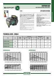
ISTRUZIONI PER L'INSTALLAZIONE E LA MANUTENZIONE<br />
INSTRUCTIONS POUR L’INSTALLATION ET LA MAINTENANCE<br />
INSTRUCTIONS FOR INSTALLATION AND MAINTENANCE<br />
INSTALLATIONS- UND WARTUNGSANLEITUNGEN<br />
INSTRUCTIES VOOR INSTALLATIE EN ONDERHOUD<br />
INSTRUCCIONES PARA LA INSTALACIÓN Y EL MANTENIMIENTO<br />
KURMA VE BAKIM B�LG�LER�<br />
����������� �� ������� � ������������ ������������<br />
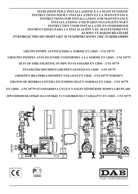
GRUPPI POMPE ANTINCENDIO A NORME EN 12845 – UNI 10779<br />
GROUPES POMPES ANTI-INCENDIE CONFORMES À LA NORME EN 12845 – UNI 10779<br />
SETS OF FIRE-FIGHTING PUMPS TO STANDARD EN 12845 – UNI 10779<br />
FEUERLÖSCHPUMPEN-GRUPPEN GEMÄSS EN 12845 – UNI 10779<br />
GROEPEN BRANDBLUSPOMPEN VOLGENS EN 12845 – UNI 10779 NORMEN<br />
GRUPOS DE BOMBAS CONTRA INCENDIOS SEGÚN NORMAS EN 12845 – UNI 10779<br />
EN 12845 – UNI 10779 STANDARDINA UYGUN YANGIN SÖNDÜRME POMPA GRUPLARI<br />
��������������� �������� ��������� �� ��������� EN 12845 – UNI 10779
DICHIARAZIONI DI CONFORMITÀ :<br />
MARCATURA CE<br />
La Ditta <strong>DAB</strong> PUMPS s.p.a. - Via M. Polo,14 - Mestrino (PD) - ITALY - sotto <strong>la</strong> propria esclusiva responsabilità dichiara<br />
che i prodotti sotto menzionati sono conformi a:<br />
��Direttiva del Consiglio n° 2006/42/CE concernente il riavvicinamento delle legis<strong>la</strong>zioni degli Stati membri CEE re<strong>la</strong>tive<br />
alle macchine e successive modifiche.<br />
��Direttiva del<strong>la</strong> Compatibilità elettromagnetica 2004/108/CE e successive modifiche.<br />
��Direttiva Bassa Tensione 2006/95/CE e successive modifiche.<br />
NORMATIVA EN 12845 – UNI 10779 ANTINCENDIO<br />
Si dichiara che il gruppo d’alimentazione idrica <strong>per</strong> impianto antincendio sotto riportato è stato fornito in conformità al<strong>la</strong><br />
normativa EN 12845 – UNI 10779 <strong>per</strong> quanto concerne i componenti idraulici e loro disposizione e le apparecchiature di<br />
comando e controllo. Le pompe costitutive del gruppo sono conformi al<strong>la</strong> normativa UNI EN 23661.<br />
DÉCLARATIONS DE CONFORMITÉ :<br />
MARQUAGE CE<br />
La société <strong>DAB</strong> PUMPS s.p.a. - Via M. Polo,14 - Mestrino (PD) - ITALY – sous sa propre responsabilité exclusive, déc<strong>la</strong>re<br />
que les produits mentionnés ci-après sont conformes à :<br />
��Directive du Conseil n° 2006/42/CE concernant l’harmonisation des légis<strong>la</strong>tions des états membres de <strong>la</strong> CEE re<strong>la</strong>tives<br />
aux machines et modifications successives.<br />
��Directive de <strong>la</strong> Compatibilité électromagnétique 2004/108/CE et modifications successives.<br />
��Directive Basse Tension 2006/95/CE et modifications successives.<br />
NORME EN 12845 – UNI 10779 ANTI-INCENDIE<br />
Nous déc<strong>la</strong>rons que le groupe d’alimentation hydraulique pour instal<strong>la</strong>tion anti-incendie indiqué ci-dessous a été fourni en<br />
conformité avec <strong>la</strong> norme EN 12845 – UNI 10779 en ce qui concerne les composants hydrauliques et leur disposition et les<br />
appareils de commande et de contrôle. Les pompes constituant le groupe sont conformes à <strong>la</strong> norme UNI EN 23661.<br />
DECLARATION OF CONFORMITY<br />
CE MARKING<br />
The Company <strong>DAB</strong> PUMPS s.p.a. - Via M. Polo,14 - Mestrino (PD) - ITALIA - under its own exclusive responsibility<br />
dec<strong>la</strong>res that the products listed below comply with:<br />
��Council Directive n° 2006/42/EC concerning the reconciliation of the legis<strong>la</strong>tion of EEC member countries re<strong>la</strong>ted to<br />
machinery and subsequent modifications.<br />
��Directive on Electromagnetic Compatibility 2004/108/EC and subsequent modifications.<br />
��Directive on Low Voltage 2006/95/EC and subsequent modifications.<br />
FIRE-FIGHTING STANDARD EN 12845 – UNI 10779<br />
It is dec<strong>la</strong>red that the water supply set for a fire-fighting system listed below has been supplied in conformity with standard<br />
EN 12845 – UNI 10779 as regards the hydraulic components and their arrangement and the command and control<br />
equipment. The pumps that make up the set comply with standard UNI EN 23661.<br />
KONFORMITÄTSERKLÄRUNG<br />
CE-KENNZEICHNUNG<br />
Die Firma <strong>DAB</strong> PUMPS s.p.a. - Via M. Polo, 14 - Mestrino (PD) - ITALIEN – erklärt eigenverantwortlich, dass die<br />
vorstehend angeführten Produkte den folgenden Richtlinien entsprechen:<br />
��Richtlinie des Rats Nr. 2006/42/EG betreffend die Angleichung der Rechtsverordnungen der Mitgliedstaaten für<br />
Maschinen und folgenden Änderungen.<br />
��Richtlinie zur elektromagnetischen Verträglichkeit 2004/108/EG und folgende Änderungen.<br />
��Niederspannungsrichtlinie 2006/95/EG und folgende Änderungen.<br />
NORM EN 12845 – UNI 10779 ZUR BRANDBEKÄMPFUNG<br />
Wir erklären, dass die Wasserversorgungseinheit der nachstehend beschriebenen Feuerlöschan<strong>la</strong>ge hinsichtlich der<br />
Hydraulikkomponenten und deren Anordnung, sowie der Steuer- und Kontrollegeräte der Norm EN 12845 – UNI 10779<br />
entspricht. Die Pumpen der Gruppe sind konform mit der Norm UNI EN 23661.<br />
OVEREENKOMSTIGHEIDSVERKLARING:<br />
CE-MARKERING<br />
De firma <strong>DAB</strong> PUMPS s.p.a. - Via M. Polo,14 - Mestrino (PD) - ITALY – verk<strong>la</strong>art onder haar eigen, exclusieve<br />
verantwoording dat de hieronder genoemde producten voldoen aan:<br />
��Richtlijn van de raad nr. 2006/42/CE met betrekking tot de onderlinge aanpassing van de wetgevingen van de lidstaten<br />
van de EEG met betrekking tot machines, en successievelijke wijzigingen.<br />
��Richtlijn elektromagnetische compatibiliteit 2004/108/CE en successievelijke wijzigingen.<br />
��Laagspanningsrichtlijn 2006/95/CE en successievelijke wijzigingen.<br />
EN 12845 - UNI 10779 NORMEN MET BETREKKING TOT BRANDBEVEILIGING<br />
Hierbij verk<strong>la</strong>ren wij dat de hieronder vermelde watertoevoereenheid voor brandblussysteem bij de aflevering voldoet aan<br />
de EN 12845 – UNI 10779 normen met betrekking tot de hydraulische componenten en hun p<strong>la</strong>atsing en de bedienings- en<br />
rege<strong>la</strong>pparatuur. De pompen van de groep zijn conform de norm UNI EN 23661.
DECLARACIÓN DE CONFORMIDAD<br />
MARCADO CE<br />
La empresa <strong>DAB</strong> PUMPS s.p.a. - Via M. Polo,14 - Mestrino (PD) - ITALY - dec<strong>la</strong>ra bajo su exclusiva responsabilidad que los<br />
productos mencionados anteriormente cumplen <strong>la</strong>:<br />
��Directiva del Consejo n° 2006/42/CE concerniente <strong>la</strong> armonización de <strong>la</strong>s legis<strong>la</strong>ciones de los estados miembros CEE, re<strong>la</strong>tivas<br />
a <strong>la</strong>s máquinas y sus modificaciones.<br />
��Directiva de Compatibilidad Electromagnética 2004/108/CE y sus modificaciones.<br />
��Directiva de Baja Tensión 2006/95/CE y sus modificaciones.<br />
NORMATIVA EN 12845 – UNI 10779 CONTRA INCENDIOS<br />
Se dec<strong>la</strong>ra que el grupo de alimentación hídrica para <strong>la</strong> insta<strong>la</strong>ción contra incendios presentado a continuación se ha suministrado<br />
en conformidad a <strong>la</strong> normativa EN 12845 – UNI 10779 en re<strong>la</strong>ción a los componentes hidráulicos y a <strong>la</strong> disposición de los<br />
aparatos de mando y control. Las bombas que constituyen el grupo cumplen <strong>la</strong> norma UNI EN 23661.<br />
UYGUNLUK BEYANNAMES�<br />
CE MARKASI<br />
<strong>DAB</strong> PUMPS s.p.a. �irketi - Via M. Polo, 14 - Mestrino (PD) - �TALYA - münhas�ran kendi �ahsi mesuliyeti alt�nda yukar�da söz<br />
konusu edilen ürünlerin a�a��daki direktiflere uygun olduk<strong>la</strong>r�n� beyan eder:<br />
��AET üyesi ülkelerin makinelere ili�kin yasa<strong>la</strong>r�n�n birbirlerine yak�n<strong>la</strong>�t�r�lmas�na yönelik 2006/42/AB say�l� Konsey Direktifi<br />
ve sonraki de�i�iklikleri.<br />
��2004/108/AB say�l� Elektromanyetik Uyumluluk Direktifi ve sonraki de�i�iklikler.<br />
��2006/95/AB say�l� Alçak Gerilim Direktifi ve sonraki de�i�iklikler.<br />
EN 12845 YANGIN SÖNDÜRME STANDARDI<br />
A�a��da belirtirken yang�n söndürme tesisi için su besleme grubunun, hidrolik bile�ikler ve bun<strong>la</strong>r�n konum<strong>la</strong>nd�r�lmas� ve<br />
kumanda ve kontrol aparat<strong>la</strong>r�na ili�kin o<strong>la</strong>rak EN 12845 – UNI 10779 standard�na uygun o<strong>la</strong>rak tedarik edilmi� oldu�u beyan<br />
edilir. Sistemi olu�turan pompa<strong>la</strong>r, UNI EN 23661 standard�n�n hükümlerine uygundur.<br />
��������� � ������������ :<br />
���������� CE<br />
�������� <strong>DAB</strong> PUMPS s.p.a. - Via M. Polo,14 - Mestrino (PD) - ITALY – ��� ����������� ��������������<br />
��������������� ��������, ��� ������������� ���� ������� �������������:<br />
����������� ������ � 2006/42/CE, ���������� ��������� ��������������� �����-������ ��, ������������ ���������<br />
������������ � ����������� ������������.<br />
����������� �� ���������������� ������������� 2004/108/CE � ����������� ������������.<br />
����������� �� ������� ���������� 2006/95/CE � ����������� ������������.<br />
�������� EN 12845 – UNI 10779 ��������������� ����<br />
����������, ��� ���� ������ ���� � ��������������� ���������, ��������� �����, ������������� ��������� EN 12845 –<br />
UNI 10779, � ���, ��� �������� �������������� �����������, �� ������������, ������������ �� ���������� � ��������.<br />
������, �������� � ����, ������������� ��������� UNI EN 23661.<br />
Mestrino (PD), 22/06/2009<br />
Francesco Sinico<br />
Technical Director
ITALIANO pag 1<br />
FRANÇAIS page 15<br />
ENGLISH page 30<br />
DEUTSCH Seite 45<br />
NEDERLANDS b<strong>la</strong>dz 60<br />
ESPAÑOL pág 75<br />
TÜRKÇE sayfa 90<br />
������� ���. 105
9a<br />
11<br />
4<br />
6<br />
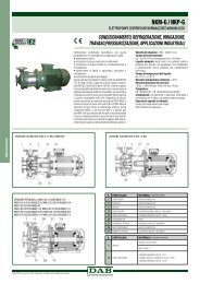
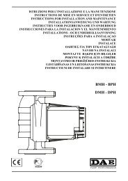
ITALIANO<br />
GRUPPO ANTINCENDIO A NORME EN 12845 – UNI 10779<br />
Elettropompa Principale<br />
3<br />
7<br />
5<br />
1 Elettropompa KDN + Pompa Pilota<br />
9a<br />
1<br />
7<br />
ATTENZIONE!<br />
IL GRUPPO VIENE FORNITO CON TAPPO DI SCARICO CORPO POMPA SVITATO!<br />
IL TAPPO DI SCARICO SI TROVA NEL SACCHETTO FISSATO AL GRUPPO!<br />
P1 Elettropompa 6 Tronchetto eccentrico di aspirazione (OPTIONAL)<br />
P3 Pompa Pilota 7 Piedi di rego<strong>la</strong>zione (fissabili a terra)<br />
1 Quadro elettrico Pompa Pilota 8 Connessione 1/2” – prova valvo<strong>la</strong> di ritegno<br />
2 Quadro elettrico Elettropompa 9a Sfiato aria pompa e ricircolo 3/8”<br />
3 Pressostati avviamento Pompa<br />
Connessione 2”<br />
10<br />
da collegare al fondo del serbatoio di adescamento<br />
4 Valvo<strong>la</strong> di ritegno 11 Pressostato Pompa in moto<br />
5 Valvo<strong>la</strong> di avviamento manuale 12 Collettore di mandata<br />
2<br />
1<br />
12<br />
8<br />
7<br />
P1<br />
10<br />
Elettropompa Pilota<br />
1<br />
P3
9a<br />
18<br />
4<br />
6<br />
3<br />
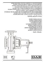
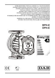
ITALIANO<br />
GRUPPO ANTINCENDIO A NORME EN 12845 – UNI 10779<br />
17<br />
5<br />
19<br />
Elettropompa Principale<br />
1 Motopompa Diesel KDN + Pompa Pilota<br />
9a<br />
16<br />
P2 Motopompa Diesel 10<br />
Connessione 2”<br />
da collegare al fondo del serbatoio di adescamento<br />
P3 Pompa Pilota 11 Quadro elettrico Motopompa Diesel<br />
1 Quadro elettrico pompa pilota 12 Collettore di mandata<br />
3 Pressostati avviamento pompa 14 Serbatoio Motopompa Diesel<br />
4 Valvo<strong>la</strong> di ritegno 15 Batterie d’avviamento Motopompa Diesel<br />
5 Valvo<strong>la</strong> di avviamento manuale 16 Motore Diesel<br />
6 Tronchetto eccentrico di aspirazione (OPTIONAL) 17 Giunto Antivibrante<br />
8 Connessione 1/2” – prova valvo<strong>la</strong> di ritegno 18 Pressostato Pompa in moto<br />
9a Sfiato aria pompa e ricircolo 3/8” 19 Basamento (fissabile a terra)<br />
2<br />
1<br />
15<br />
ATTENZIONE!<br />
IL GRUPPO VIENE FORNITO CON TAPPO DI SCARICO CORPO POMPA SVITATO!<br />
IL TAPPO DI SCARICO SI TROVA NEL SACCHETTO FISSATO AL GRUPPO!<br />
11<br />
14<br />
8<br />
P2<br />
12<br />
10<br />
Elettropompa Pilota<br />
1<br />
P3
9a<br />
18<br />
4<br />
6<br />
3<br />
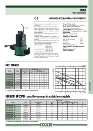
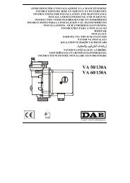
ITALIANO<br />
GRUPPO ANTINCENDIO A NORME EN 12845 – UNI 10779<br />
1 Motopompa Diesel + 1 Elettropompa KDN + Pompa Pilota<br />
5<br />
17<br />
19<br />
Elettropompa Principale<br />
1<br />
9a<br />
16<br />
2<br />
P1 Elettropompa 9a Sfiato aria pompa e ricircolo 3/8”<br />
P2 Motopompa Diesel 10<br />
Connessione 2”da collegare<br />
al fondo del serbatoio di adescamento<br />
P3 Pompa Pilota 11 Quadro elettrico Motopompa Diesel<br />
1 Quadro elettrico Pompa Pilota 12 Collettore di mandata<br />
2 Quadro elettrico Elettropompa 13<br />
Collettore d’unione<br />
Motopompa Diesel ad Elettropompa<br />
3 Pressostati avviamento pompa 14 Serbatoio Motopompa Diesel<br />
4 Valvo<strong>la</strong> di ritegno 15 Batterie d’avviamento Motopompa Diesel<br />
5 Valvo<strong>la</strong> di avviamento manuale 16 Motore Diesel<br />
6 Tronchetto eccentrico di aspirazione (OPTIONAL) 17 Giunto Antivibrante<br />
7 Piedi di rego<strong>la</strong>zione (fissabili a terra) 18 Pressostato Pompa in moto<br />
8 Connessione 1/2” – prova valvo<strong>la</strong> di ritegno 19 Basamento (fissabile a terra)<br />
15<br />
3<br />
11<br />
14<br />
8<br />
12 13 12<br />
ATTENZIONE!<br />
IL GRUPPO VIENE FORNITO CON TAPPO DI SCARICO CORPO POMPA SVITATO!<br />
IL TAPPO DI SCARICO SI TROVA NEL SACCHETTO FISSATO AL GRUPPO!<br />
P1<br />
10<br />
7<br />
P2<br />
Elettropompa Pilota<br />
P3
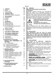
ITALIANO<br />
GRUPPO ANTINCENDIO A NORME EN 12845 – UNI 10999<br />
Elettropompa Principale<br />
1 Elettropompa NKV + Pompa Pilota<br />
2<br />
3<br />
4<br />
5<br />
6<br />
7<br />
9a<br />
1<br />
8<br />
ATTENZIONE!<br />
IL GRUPPO VIENE FORNITO CON TAPPO DI SCARICO CORPO POMPA SVITATO!<br />
IL TAPPO DI SCARICO SI TROVA NEL SACCHETTO FISSATO AL GRUPPO!<br />
1<br />
Quadro di comando indipendente <strong>per</strong> ogni pompa<br />
principale<br />
10 Pressostato pompa in moto<br />
2 Quadro di comando pompa pilota 11 Sistema di prova <strong>per</strong> valvo<strong>la</strong> di ritegno<br />
3 Pompa pilota 12 Aspirazioni indipendenti<br />
4 Pressostato <strong>per</strong> pompa pilota 13 Valvo<strong>la</strong> di ritegno su pompa di servizio<br />
5 Valvo<strong>la</strong> di intercettazione lucchettabile 14 Attacco 1” <strong>per</strong> flussostato sprinkler locale pompe<br />
6 Circuito pressostati di avviamento 15 Unico collettore di mandata<br />
7 Fori <strong>per</strong> fissaggio a terra 16 Vaso d’espansione <strong>per</strong> pompa pilota<br />
8 Attacco 2” <strong>per</strong> serbatoio adescamento<br />
9 Attacco ¼” <strong>per</strong> ricircolo acqua<br />
9a Sfiato aria pompa e ricircolo 3/8”<br />
4<br />
9<br />
16<br />
15<br />
14<br />
13<br />
12<br />
11<br />
10<br />
Elettropompa Pilota
ITALIANO<br />
GRUPPO ANTINCENDIO A NORME EN 12845 – UNI 10999<br />
Elettropompa Principale<br />
2<br />
3<br />
4<br />
5<br />
6<br />
2 Elettropompe NKV + Pompa Pilota<br />
9a<br />
1<br />
7 8 9<br />
ATTENZIONE!<br />
IL GRUPPO VIENE FORNITO CON TAPPO DI SCARICO CORPO POMPA SVITATO!<br />
IL TAPPO DI SCARICO SI TROVA NEL SACCHETTO FISSATO AL GRUPPO!<br />
1<br />
Quadro di comando indipendente <strong>per</strong> ogni pompa<br />
principale<br />
10 Pressostato pompa in moto<br />
2 Quadro di comando pompa pilota 11 Sistema di prova <strong>per</strong> valvo<strong>la</strong> di ritegno<br />
3 Pompa pilota 12 Aspirazioni indipendenti<br />
4 Pressostato <strong>per</strong> pompa pilota 13 Valvo<strong>la</strong> di ritegno su pompa di servizio<br />
5 Valvo<strong>la</strong> di intercettazione lucchettabile 14 Attacco 1” <strong>per</strong> flussostato sprinkler locale pompe<br />
6 Circuito pressostati di avviamento 15 Unico collettore di mandata<br />
7 Fori <strong>per</strong> fissaggio a terra 16 Vaso d’espansione <strong>per</strong> pompa pilota<br />
8 Attacco 2” <strong>per</strong> serbatoio adescamento<br />
9 Attacco ¼” <strong>per</strong> ricircolo acqua<br />
9a Sfiato aria pompa e ricircolo 3/8”<br />
5<br />
16<br />
15<br />
14<br />
13<br />
12<br />
11<br />
10<br />
Elettropompa Pilota
ITALIANO<br />
GRUPPO ANTINCENDIO EN 12845 – UNI 10779<br />
SCHEMA IDRAULICO ALIMENTAZIONE SOTTOBATTENTE<br />
2<br />
2<br />
6<br />
2<br />
9<br />
16<br />
20<br />
COLLETTORE DI MANDATA ALL’IMPIANTO<br />
7 8<br />
7<br />
5<br />
4 4<br />
3 3<br />
2<br />
13<br />
17<br />
10<br />
14<br />
1 1 1<br />
* Componenti e materiali NON compresi nel<strong>la</strong> fornitura del gruppo pompe antincendio<br />
P1 Pompa di alimentazione nr.1 13 Valvo<strong>la</strong> di intercettazione pressostato<br />
P2 Pompa di alimentazione nr.2 14 Valvo<strong>la</strong> di non ritorno circuito di prova manuale<br />
P3 Pompa Pilota 15 Valvo<strong>la</strong> di prova manuale pompa principale<br />
1* Valvo<strong>la</strong> intercettazione aspirazione 16 Valvo<strong>la</strong> di intercettazione in mandata<br />
2* Filtro di aspirazione 17 Pressostato avviamento pompa nr.1<br />
3 Sfiato aria pompa e ricircolo 18 Pressostato avviamento pompa nr.2<br />
4* Valvo<strong>la</strong> di prova / di non ritorno 19* Tronchetto misuratore di portata<br />
5 Valvo<strong>la</strong> di non ritorno 20* Valvo<strong>la</strong> di intercettazione misuratore di portata<br />
6* Riserva idrica 21* Misuratore di portata<br />
7 Valvo<strong>la</strong> di non ritorno<br />
8 Valvo<strong>la</strong> intercettazione in mandata<br />
9* Tubazione <strong>per</strong> sfiato aria pompa e ricircolo<br />
10 Vaso di espansione a membrana<br />
11 Pressostato pompa pilota<br />
12 Manometro<br />
6<br />
17<br />
2<br />
13<br />
15<br />
11<br />
12<br />
12<br />
TRONCHETTO MISURATORE<br />
16<br />
2<br />
21<br />
13<br />
19<br />
18<br />
14<br />
18<br />
13<br />
15<br />
12
ITALIANO<br />
GRUPPO ANTINCENDIO EN 12845 – UNI 10779<br />
SCHEMA IDRAULICO ALIMENTAZIONE SOPRABATTENTE<br />
5<br />
26<br />
24<br />
2<br />
22<br />
20<br />
25<br />
27<br />
8 9<br />
8<br />
4 4<br />
3<br />
28<br />
COLLETTORE DI MANDATA<br />
16 17 17<br />
16<br />
6<br />
14<br />
10<br />
13<br />
3 3<br />
1 1 1<br />
7<br />
14<br />
15<br />
12<br />
11<br />
11<br />
6<br />
* Componenti e materiali NON compresi nel<strong>la</strong> fornitura del gruppo pompe antincendio<br />
P1 Pompa di alimentazione nr.1 14 Valvo<strong>la</strong> di intercettazione pressostato<br />
P2 Pompa di alimentazione nr.2 15 Valvo<strong>la</strong> di prova manuale pompa principale<br />
P3 Pompa Pilota 16 Valvo<strong>la</strong> di intercettazione in mandata<br />
1* Filtro aspirazione 17 Pressostato avviamento elettropompa nr.1<br />
2* Riserva idrica 18 Pressostato avviamento elettropompa nr.2<br />
3* Valvo<strong>la</strong> di fondo 19* Tronchetto misuratore di portata<br />
4 Sfiato aria pompa e ricircolo 20* Valvo<strong>la</strong> di non ritorno linea di adescamento<br />
5* Tubazione <strong>per</strong> sfiato aria pompa e ricircolo 21* Valvo<strong>la</strong> di intercettazione misuratore di portata<br />
6* Valvo<strong>la</strong> di prova / di non ritorno 22* Valvo<strong>la</strong> di intercettazione linea di adescamento<br />
7 Valvo<strong>la</strong> di non ritorno 23* Misuratore di portata<br />
8 Valvo<strong>la</strong> di non ritorno 24* Valvo<strong>la</strong> di scarico serbatoio<br />
9 Valvo<strong>la</strong> di intercettazione in mandata 25* Galleggiante serbatoio<br />
10 Vaso di espansione a membrana 26* Scarico troppo pieno<br />
11 Manometro 27* Serbatoio di adescamento<br />
12 Pressostato pompa pilota 28* Reintegro serbatoio<br />
13 Valvo<strong>la</strong> di non ritorno circuito prova manuale<br />
7<br />
23<br />
21<br />
14<br />
19<br />
13<br />
14<br />
15<br />
ALL’IMPIANTO<br />
11<br />
5<br />
26<br />
24<br />
22<br />
20<br />
25<br />
27<br />
28
ITALIANO<br />
INDICE pag.<br />
1. GENERALITA’ 8<br />
2. AVVERTENZE 8<br />
2.1. Personale Tecnico Qualificato 8<br />
2.2. Sicurezza 8<br />
2.3. Responsabilità 8<br />
3. INSTALLAZIONE 8<br />
3.7 O<strong>per</strong>azioni necessarie <strong>per</strong> l’avviamento del<strong>la</strong> Motopompa Diesel 9<br />
3.9 Gas di scarico Motopompe Diesel 10<br />
3.10. Venti<strong>la</strong>zione <strong>per</strong> motore Diesel 10<br />
4. ALLACCIAMENTO ELETTRICO 10<br />
5. COLLEGAMENTI MOTOPOMPA DIESEL 10<br />
6 VERIFICA FUNZIONAMENTO DEL GRUPPO 10<br />
6.1. Verifica funzionamento dell’Elettropompa 10<br />
6.2. Verifica funzionamento dell’Elettropompa di Compensazione (Pompa Pilota) 11<br />
6.3. Verifica funzionamento del<strong>la</strong> Motopompa Diesel 11<br />
6.4. Gruppi con più pompe 11<br />
7 MANUTENZIONE PERIODICA 12<br />
7.1. Controllo settimanale 12<br />
7.2. Controllo mensile 12<br />
7.3. Controllo trimestrale 12<br />
7.4. Controllo semestrale 12<br />
7.5. Controllo annuale 12<br />
7.6. Controllo triennale 12<br />
7.7. Controllo decennale 12<br />
8. REGOLAZIONE DEL GRUPPO 13<br />
8.1. Taratura pressostati 13<br />
9. ELETTROPOMPA DI COMPENSAZIONE 13<br />
10. MANUTENZIONE 13<br />
10.2 Ricerca e soluzione inconvenienti 13<br />
1. GENERALITÀ<br />
Prima di procedere all’instal<strong>la</strong>zione leggere attentamente questa documentazione. L’instal<strong>la</strong>zione ed il<br />
funzionamento dovranno essere conformi al<strong>la</strong> rego<strong>la</strong>mentazione di sicurezza del paese di instal<strong>la</strong>zione del<br />
prodotto. Tutta l’o<strong>per</strong>azione dovrà essere eseguita a rego<strong>la</strong> d’arte ed esclusivamente da <strong>per</strong>sonale tecnico<br />
qualificato (paragrafo 2.1) in possesso dei requisiti richiesti dalle normative vigenti. Il mancato rispetto delle<br />
norme di sicurezza, oltre a creare <strong>per</strong>icolo <strong>per</strong> l’incolumità delle <strong>per</strong>sone e danneggiare le apparecchiature, farà<br />
decadere ogni diritto di intervento in garanzia.<br />
Conservare con cura questo manuale <strong>per</strong> ogni ulteriore consultazione anche dopo <strong>la</strong> prima instal<strong>la</strong>zione.<br />
2. AVVERTENZE<br />
2.1. Personale tecnico qualificato<br />
È indispensabile che l’instal<strong>la</strong>zione venga eseguita da <strong>per</strong>sonale competente e qualificato, in<br />
possesso dei requisiti tecnici richiesti dalle normative specifiche in materia.<br />
Per <strong>per</strong>sonale qualificato si intendono quelle <strong>per</strong>sone che <strong>per</strong> <strong>la</strong> loro formazione, es<strong>per</strong>ienza ed istruzione,<br />
nonché le conoscenze delle re<strong>la</strong>tive norme, prescrizioni provvedimenti <strong>per</strong> <strong>la</strong> prevenzione degli incidenti e sulle<br />
condizioni di servizio, sono stati autorizzati dal responsabile del<strong>la</strong> sicurezza dell’impianto ad eseguire qualsiasi<br />
necessaria attività ed in questa essere in grado di conoscere ed evitare qualsiasi <strong>per</strong>icolo. (Definizione <strong>per</strong> il<br />
<strong>per</strong>sonale tecnico qualificato IEC 60634)<br />
2.2. Sicurezza<br />
L’utilizzo è consentito so<strong>la</strong>mente se l’impianto elettrico è contraddistinto da misure di sicurezza secondo le Normative vigenti<br />
nel paese di instal<strong>la</strong>zione del prodotto (<strong>per</strong> l’Italia CEI 64/2).<br />
2.3. Responsabilità<br />
Il costruttore non risponde del buon funzionamento del gruppo o di eventuali danni da questo provocato,<br />
qualora lo stesso venga manomesso, modificato e/o fatto funzionare fuori dal campo di <strong>la</strong>voro consigliato o<br />
senza l’ausilio dei nostri quadri di comando e protezione.<br />
Declina inoltre ogni responsabilità <strong>per</strong> le possibili inesattezze contenute nel presente manuale <strong>istruzioni</strong>, se<br />
dovute ad errori di stampa o di trascrizione. Si riserva il diritto di apportare ai prodotti quelle modifiche<br />
che riterrà necessarie od utili, senza pregiudicarne le caratteristiche essenziali.<br />
3. INSTALLAZIONE<br />
3.1.<br />
Il gruppo deve essere instal<strong>la</strong>to in luogo ben aereato, protetto dalle intem<strong>per</strong>ie, e con tem<strong>per</strong>atura<br />
ambiente non inferiore ai 4°C (10°C nel caso fossero instal<strong>la</strong>te anche motopompe), e non su<strong>per</strong>iore ai<br />
40°C. Posizionare il gruppo in maniera che eventuali o<strong>per</strong>azioni di <strong>manutenzione</strong> possano essere<br />
effettuate senza difficoltà.<br />
8
3.2.<br />
ITALIANO<br />
Accertarsi che le tubazioni dell’impianto siano supportate in maniera autonoma e non gravino col proprio<br />
peso sui collettori del gruppo <strong>per</strong> evitare deformazioni o rotture di qualche suo componente.<br />
3.3. E’ consigliabile collegare le tubazioni di aspirazione e mandata all’impianto interponendo dei giunti antivibranti,<br />
specialmente in caso di instal<strong>la</strong>zione di motopompe Diesel.<br />
3.4.<br />
Assicurarsi che le caratteristiche del<strong>la</strong> fonte di alimentazione idrica siano tali da garantire sempre il prelievo<br />
di portata richiesto nelle condizioni d’esercizio previste.<br />
3.5. Realizzare il tratto aspirante seguendo tutti quegli accorgimenti necessari a rendere minime le <strong>per</strong>dite di carico e ad<br />
evitare il formarsi di sacche d’aria, come:<br />
a) Posizionare il gruppo il più vicino possibile al<strong>la</strong> fonte di alimentazione.<br />
b) Dotare ciascuna pompa di una propria condotta di aspirazione (EN 12845 – UNI 10779).<br />
c) Posare le tubazioni aspiranti orizzontalmente o con pendenza leggermente ascendente verso il gruppo.<br />
d) Evitare di impiegare gomiti o raccordi che provochino brusche variazioni di direzione. Se necessario usare curve ad<br />
ampio raggio.<br />
e)<br />
Evitare in aspirazione l’effetto “sifone”: rischio di disinnesco delle pompe!<br />
3.6. La distanza verticale tra l’aspirazione del<strong>la</strong> pompa ed il minimo livello dell’acqua non deve eccedere i 3,2 metri.<br />
(EN 12845 – punto 10.6.2.3 – UNI 10779)<br />
3.7. OPERAZIONI NECESSARIE PER L’AVVIAMENTO DELLA MOTOPOMPA DIESEL<br />
TUTTI I GRUPPI MOTOPOMPA DIESEL VENGONO CONSEGNATI A SECCO, SENZA<br />
GASOLIO, OLIO MOTORE E LIQUIDO REFRIGERANTE!<br />
IL GRUPPO NON DEVE ESSERE AVVIATO PRIMA DI AVERE INSERITO IL GASOLIO,<br />
L’OLIO MOTORE E IL LIQUIDO REFRIGERANTE!<br />
a) Rifornire il serbatoio del<strong>la</strong> motopompa Diesel con gasolio fino al massimo livello <strong>per</strong> garantire 3-4-6 ore di<br />
autonomia a seconda delle c<strong>la</strong>ssi di richio dell’impianto (EN 12845 punto 10.9.9 – UNI 10779).<br />
I gruppi motopompa <strong>DAB</strong> garantiscono 6 ore di autonomia.<br />
b) RIEMPIRE IL MOTORE CON OLIO LUBRIFICANTE 15 W 40, come indicato nel<strong>la</strong> seguente tabel<strong>la</strong>.<br />
(verificare il livello dell’olio di lubrificazione del motore tramite apposita astina).<br />
MOTORE DIESEL TIPO<br />
QUANTITA’<br />
TIPO LIQUIDO<br />
OLIO LUBRIFICANTE<br />
OLIO<br />
REFRIGERANTE<br />
11 kW (25LD 425/2) 15W-40 2 litri NO<br />
15 kW (12LD 477/2) 15W-40 3 litri NO<br />
19 kW (9LD 626/2) 15W-40 2,8 litri NO<br />
26 kW (11LD 626/3) 15W-40 5 litri NO<br />
37 kW (D703L) 15W-40 5 litri<br />
3,7 litri<br />
(1,5 l antigelo + 2,2 l acqua)<br />
53kW (D703LT) 15W-40 8 litri<br />
3,7 litri<br />
(1,5 l antigelo + 2,2 l acqua)<br />
68 kW (D704LT) 15W-40 10 litri<br />
5 litri<br />
(2 l antigelo + 3 l acqua)<br />
94 kW (D706LT) 15W-40 10 litri<br />
7,5 litri<br />
(3 l antigelo + 4,5 l acqua)<br />
109 kW (N45-MNSF40.10) 15W-40 13 litri<br />
8 litri<br />
(3,5 l antigelo + 4,5 l acqua)<br />
8061 SI40 132kW 15W-40 12 litri<br />
9 litri<br />
8061 SRI40 167kW 15W-40 12 litri<br />
9<br />
(3,5 l antigelo + 5,5 l acqua)<br />
9 litri<br />
(3,5 l antigelo + 5,5 l acqua)<br />
c) Riempire il filtro d’aspirazione aria con apposito olio come da <strong>istruzioni</strong> allegate al motore Diesel.<br />
3.8. La motopompa Diesel, pur essendo più affidabile rispetto all’elettropompa (funziona anche in caso di b<strong>la</strong>ck out),<br />
necessita di partico<strong>la</strong>ri accorgimenti atti ad evitare rumorosità eccessiva, vibrazioni, contaminazione da gas di scarico,<br />
surriscaldamento.<br />
Di seguito vengono riportati alcuni accorgimenti da adottare <strong>per</strong> ottenere <strong>la</strong> massima efficienza durante il funzionamento.
ITALIANO<br />
3.9. GAS DI SCARICO MOTOPOMPA DIESEL<br />
Portare all’esterno del locale pompe i gas di scarico tramite tubazione dedicata, collegata al<strong>la</strong> marmitta<br />
silenziatrice fornita con <strong>la</strong> motopompa Diesel.<br />
La tubazione di scarico può correre lungo il soffitto od il pavimento.<br />
Dev’essere protetta dalle intem<strong>per</strong>ie e dotata di drenaggio <strong>per</strong> lo scarico di eventuale condensa.<br />
Per evitare il su<strong>per</strong>amento del massimo valore di contropressione allo scarico (600 mm H2O <strong>per</strong> i motori raffreddati ad<br />
aria e 1000 mm H2O <strong>per</strong> quelli sovralimentati – raffreddati ad acqua), si consiglia inoltre di adottare i seguenti<br />
accorgimenti:<br />
�� La tubazione non deve su<strong>per</strong>are i 10 metri di lunghezza.<br />
�� La sezione del<strong>la</strong> tubazione dev’essere mantenuta pari all’uscita del<strong>la</strong> marmitta fornita.<br />
�� Per il calcolo del<strong>la</strong> sezione del<strong>la</strong> tubazione oltre i 10 metri di lunghezza considerare il valore del<strong>la</strong> sezione del tubo<br />
di uscita del<strong>la</strong> marmitta, moltiplicarlo <strong>per</strong> <strong>la</strong> lunghezza del<strong>la</strong> tubazione stessa e dividere il risultato <strong>per</strong> 8.<br />
�� Ridurre al massimo il numero di curve usate nel<strong>la</strong> tubazione (massimo n. 6) e preferire l’utilizzo di curve ad ampio<br />
raggio.<br />
3.10. VENTILAZIONE PER MOTORE DIESEL<br />
Per l’esercizio ottimale è necessario che il calore irradiato dal motore e dalle tubazioni di scarico venga smaltito<br />
verso l’esterno del locale pompe e che sia garantito un sufficiente afflusso d’aria di combustione.<br />
Nel<strong>la</strong> maggior parte dei casi <strong>la</strong> circo<strong>la</strong>zione naturale causata dal<strong>la</strong> differenza di tem<strong>per</strong>atura tra aria interna ed esterna non<br />
è sufficiente. E’ necessario quindi provvedere a:<br />
�� garantire l’immissione d’aria tramite un foro d’a<strong>per</strong>tura adeguatamente protetto da griglia fissa,<br />
�� l’utilizzo di un venti<strong>la</strong>tore <strong>per</strong> l’estrazione dell’aria dal locale pompe.<br />
Nel caso di motori raffreddati ad acqua, <strong>la</strong> su<strong>per</strong>ficie dei fori di a<strong>per</strong>tura di entrata ed uscita dell’aria deve avere almeno<br />
dimensioni pari al<strong>la</strong> su<strong>per</strong>ficie del radiatore.<br />
Nel caso di motori raffreddati ad aria, <strong>la</strong> su<strong>per</strong>ficie dei fori di a<strong>per</strong>tura deve essere tale da porter smaltire una portata<br />
d’aria di almeno 50.000 litri/min.<br />
(dati tecnici re<strong>la</strong>tivi al più grande motore Diesel raffreddato ad aria utilizzato da <strong>DAB</strong> PUMPS).<br />
4. ALLACCIAMENTO ELETTRICO<br />
ATTENZIONE: OSSERVARE LE NORME DI SICUREZZA VIGENTI<br />
4.1.<br />
L’al<strong>la</strong>cciamento elettrico deve essere effettuato esclusivamente da <strong>per</strong>sonale specializzato e<br />
qualificato (vedi punto 2.1) in osservanza alle Norme di sicurezza in vigore nel paese di<br />
instal<strong>la</strong>zione del prodotto.<br />
4.2.<br />
4.3.<br />
Control<strong>la</strong>re tensione e frequenza di alimentazione. Valori difformi a quelli di targa del motore potrebbero<br />
danneggiarlo irrimediabilmente.<br />
Eseguire l’al<strong>la</strong>cciamento dei fili del cavo di alimentazione al<strong>la</strong> morsettiera del quadro di comando, dando<br />
priorità al filo di terra.<br />
Per lo schema elettrico del quadro di comando e le re<strong>la</strong>tive note informative, vedi documentazione allegata.<br />
5. COLLEGAMENTI MOTOPOMPA DIESEL<br />
Collegare i due cavi con coprimorsetto rosso ai poli positivi delle due batterie di avviamento motopompa Diesel, utilizzando<br />
gli appositi morsetti in dotazione.<br />
DA QUESTO MOMENTO LA MOTOPOMPA DIESEL PUO’ AVVIARSI IN MODO<br />
AUTOMATICO PER ABBASSAMENTO PRESSIONE IMPIANTO !!! TENERE IL<br />
SELETTORE DEL QUADRO MOTOPOMPA IN POSIZIONE AZZERAMENTO - 0 .<br />
6. VERIFICA FUNZIONAMENTO DEL GRUPPO<br />
6.1. VERIFICA FUNZIONAMENTO DELL’ ELETTROPOMPA<br />
a) Posizionare l’interruttore generale del quadro dell’elettropompa su 1 (ON).<br />
Control<strong>la</strong>re il senso di rotazione dell’elettropompa avviando<strong>la</strong> <strong>per</strong> qualche istante tramite il pulsante di START e<br />
verificare se, osservando dal <strong>la</strong>to vento<strong>la</strong>, <strong>la</strong> rotazione del motore avviene in senso orario.<br />
In caso contrario scambiare tra loro nel<strong>la</strong> morsettiera due fili qualsiasi di alimentazione del quadro<br />
dell’elettropompa.<br />
b) Posizionare il selettore del quadro dell’elettropompa in posizione AUT.<br />
c) Aprire una valvo<strong>la</strong> dell’impianto (oppure <strong>la</strong> valvo<strong>la</strong> di avviamento manuale pompa, posta vicina ai pressostati).<br />
d) Verificare l’avvio dell’elettropompa.<br />
e) Chiudere <strong>la</strong> valvo<strong>la</strong> dell’impianto (oppure <strong>la</strong> valvo<strong>la</strong> di avviamento manuale pompa, posta vicina ai pressostati).<br />
f) Mettere in pressione l’impianto.<br />
g) Arrestare l’elettropompa tramite il pulsante STOP posto sul quadro elettrico.<br />
Per <strong>la</strong> verifica del mancato avviamento del<strong>la</strong> pompa elettrica vedere il libretto istruzione dell’elettropompa.<br />
10
ITALIANO<br />
ATTENZIONE! DURANTE IL FUNZIONAMENTO DELL’ELETTROPOMPA:<br />
�� Verificare eventuali <strong>per</strong>dite d’acqua nell’impianto, eventualmente arrestare l’elettropompa.<br />
�� Il contatto di segna<strong>la</strong>zione elettropompa in moto si chiude e può attivare gli eventuali al<strong>la</strong>rmi<br />
collegati.<br />
6.2. VERIFICA FUNZIONAMENTO DELL’ ELETTROPOMPA DI COMPENSAZIONE (POMPA PILOTA)<br />
La pompa di compensazione (o pompa pilota) è una pompa ausiliaria che interviene <strong>per</strong> piccoli prelievi d’acqua.<br />
Parte ad una pressione su<strong>per</strong>iore al<strong>la</strong> pressione di avviamento delle pompe principali e si arresta al ripristino del<strong>la</strong><br />
pressione nell’impianto.<br />
Non è obbligatoria, comunque è consigliata <strong>per</strong> evitare inutili avviamenti delle pompe principali in caso di <strong>per</strong>dite<br />
d’acqua nell’impianto.<br />
a) Posizionare l’interruttore generale del quadro dell’elettropompa su 1 (ON).<br />
Per il controllo del senso di rotazione dell’elettropompa di compensazione ( o pompa pilota), posizionare <strong>per</strong><br />
qualche istante il re<strong>la</strong>tivo selettore in MAN e verificare se, osservando dal <strong>la</strong>to vento<strong>la</strong>, <strong>la</strong> rotazione del motore<br />
avviene in senso orario.<br />
In caso contrario scambiare tra loro nel<strong>la</strong> morsettiera due fili qualsiasi di alimentazione del quadro<br />
dell’elettropompa di compensazione ( o pompa pilota).<br />
b) Posizionare il selettore del quadro dell’elettropompa in posizione AUT.<br />
c) Aprire un idrante dell’impianto.<br />
d) Verificare l’avvio dell’elettropompa di compensazione (o pompa pilota)<br />
e) Chiudere l’idrante.<br />
f) Verificare che l’elettropompa si arresti AUTOMATICAMENTE.<br />
6.3. VERIFICA FUNZIONAMENTO DELLA MOTOPOMPA DIESEL<br />
a) Posizionare l’interruttore generale del quadro del<strong>la</strong> motopompa Diesel su 1 (ON).<br />
Un riscaldatore elettrico 230V (posto sotto <strong>la</strong> coppa dell’olio <strong>per</strong> i motori raffreddati ad aria o nel<strong>la</strong> testata <strong>per</strong> i<br />
motori raffreddati ad acqua) porterà l’olio (o l’acqua) ad una tem<strong>per</strong>atura minima, in modo da facilitare<br />
l’avviamento del<strong>la</strong> motopompa.<br />
Al raggiungimento del<strong>la</strong> tem<strong>per</strong>atura minima, <strong>la</strong> spia di segna<strong>la</strong>zione del riscaldatore posta a fianco del disp<strong>la</strong>y del<br />
quadro si spegnerà.<br />
Quando <strong>la</strong> motopompa Diesel viene messa in servizio in sito <strong>per</strong> <strong>la</strong> prima volta, è<br />
necessario verificare l’al<strong>la</strong>rme mancato avviamento. (EN 12845 10.9.13.2 – UNI 10779)<br />
Vedere il libretto <strong>istruzioni</strong> del Quadro Elettrico <strong>per</strong> maggiori informazioni.<br />
b) Posizionare il selettore del quadro del<strong>la</strong> motopompa Diesel in posizione AUT.<br />
c) Aprire una valvo<strong>la</strong> dell’impianto (oppure <strong>la</strong> valvo<strong>la</strong> di avviamento manuale pompa - rif. 5)<br />
d) Verificare l’avvio del<strong>la</strong> motopompa.<br />
e) Chiudere <strong>la</strong> valvo<strong>la</strong> dell’impianto (oppure <strong>la</strong> valvo<strong>la</strong> di avviamento manuale pompa - rif. 5).<br />
f) Verificare che il numero dei giri/minuto, visualizzati sul disp<strong>la</strong>y, corrispondano a quanto indicato nel<strong>la</strong> targhetta<br />
dati posta sul comando acceleratore, eventualmente tarare l’accelleratore in base a quanto indicato nel<strong>la</strong> targhetta.<br />
g) Mettere in pressione l’impianto.<br />
h) Arrestare <strong>la</strong> motopompa tramite il pulsante STOP posto sul quadro elettrico.<br />
ATTENZIONE! DURANTE IL FUNZIONAMENTO DELLA MOTOPOMPA DIESEL:<br />
�� Verificare eventuali <strong>per</strong>dite d’acqua nell’impianto, eventualmente arrestare <strong>la</strong> motopompa.<br />
�� Il contatto di segna<strong>la</strong>zione motopompa in moto si chiude e può attivare gli eventuali al<strong>la</strong>rmi collegati.<br />
La motopompa Diesel, nel caso di mancata partenza, effettua sei tentativi di avviamento alternati sulle due batterie<br />
(EN 12845 punto 10.9.7.2 – UNI 10779).<br />
La condizione di motopompa Diesel in moto viene rilevata dal sensore di velocità posto sul motore.<br />
Se dopo i sei tentativi <strong>la</strong> motopompa non va in moto, nel quadro elettrico vengono attivati:<br />
�� una spia di segna<strong>la</strong>zione di mancato avviamento,<br />
�� un contatto di al<strong>la</strong>rme <strong>per</strong> mancato avviamento.<br />
6.4. GRUPPI CON PIU’ POMPE<br />
La normativa EN 12845 – UNI 10779 prevede varie soluzioni con una o più pompe con caratteristiche simili:<br />
�� se sono instal<strong>la</strong>te DUE pompe, ciascuna pompa fornisce <strong>la</strong> portata totale dell’impianto (100%),<br />
�� se sono instal<strong>la</strong>te TRE pompe, ciascuna pompa fornisce il 50% del<strong>la</strong> portata totale.<br />
Nei gruppi, inoltre, in cui è presente più di una pompa instal<strong>la</strong>ta in alimentazione su<strong>per</strong>iore o duplicata, solo una pompa sarà<br />
elettrica (10.2). Da questo si deduce che, nel caso di alimentazione su<strong>per</strong>iore o duplicata, i gruppi saranno composti da :<br />
a) n. 1 elettropompa (100%),<br />
b) n. 1 motopompa Diesel (100%),<br />
c) n. 1 elettropompa + n. 1 motopompa Diesel (ciascuna fornisce il 100%),<br />
d) n. 1 elettropompa + n. 2 motopompe Diesel (ciascuna fornisce il 50%),<br />
e) n. 3 motopompe Diesel (ciascuna fornisce il 50%).<br />
Nel caso di alimentazione singo<strong>la</strong>, non vi sono limitazioni sul numero di elettropompe.<br />
<strong>DAB</strong> fornisce i gruppi in versione “modu<strong>la</strong>re”, in unità separate, in modo da poter comporre tutte le sopracitate versioni.<br />
Tramite il COLLETTORE DI UNIONE (vedi disegno pag. 3) è possibile unire i collettori in modo da ottenere un unico<br />
collettore di mandata.<br />
Le aspirazioni, i quadri elettrici ecc. rimangono separati come previsto dal<strong>la</strong> norma EN 12845 – UNI 10779.<br />
11
ITALIANO<br />
7. MANUTENZIONE PERIODICA<br />
Tutto l’impianto anticendio a norme EN 12845 – UNI 10779, compreso il gruppo pompe anticendio, deve essere sempre<br />
tenuto in <strong>per</strong>fetta efficienza . Per questo motivo una rego<strong>la</strong>re <strong>manutenzione</strong> riveste una partico<strong>la</strong>re importanza.<br />
Secondo <strong>la</strong> norma EN 12845 punto 20.1.1 – UNI 10779, l’utente deve:<br />
- eseguire un programma di ispezioni e controlli;<br />
- predisporre un programma di prova, assistenza e <strong>manutenzione</strong>;<br />
- documentare e registrare le attività custodendo i documenti in apposito registro tenuto nel fabbricato.<br />
L’utente deve provvedere affinchè il programma di prova, assistenza e <strong>manutenzione</strong> sia eseguito <strong>per</strong> contratto dall’instal<strong>la</strong>tore<br />
dell’impianto o da un’azienda ugualmente qualificata.<br />
7.1. CONTROLLO SETTIMANALE (da effettuarsi ad intervalli non su<strong>per</strong>iori a 7 giorni)<br />
Il controllo settimanale del gruppo anticendio EN 12845 – UNI 10779 prevede <strong>la</strong> verifica e l’annotazione dei seguenti valori:<br />
�� pressione manometri,<br />
�� livello dell’acqua nei serbatoi – riserve d’acqua,<br />
�� corretta posizione delle valvole di intercettazione.<br />
Per effettuare <strong>la</strong> prova d’avviamento automatico delle pompe seguire <strong>la</strong> procedura di seguito elencata:<br />
� Control<strong>la</strong>re i livelli carburante ed olio lubrificante dei motori Diesel.<br />
� Aprire <strong>la</strong> valvo<strong>la</strong> di avviamento manuale pompa (rif. 5).<br />
� Verificare l’avvio del<strong>la</strong> pompa ed annotare <strong>la</strong> pressione di avvio.<br />
� Chiudere <strong>la</strong> valvo<strong>la</strong> di avviamento manuale.<br />
Nel caso di motore Diesel questo verrà fatto funzionare <strong>per</strong> almeno 5 minuti.<br />
� Arrestare <strong>la</strong> pompa tramite il pulsante di STOP posto sul quadro elettrico.<br />
OPERAZIONI SOLO PER MOTOPOMPA DIESEL<br />
� Subito dopo l’arresto, <strong>la</strong> motopompa Diesel va riavviata immediatamente tramite il pulsante di prova<br />
dell’avviamento manuale “OPERATE MANUAL START”.<br />
� Arrestare <strong>la</strong> pompa tramite il pulsante di STOP posto sul quadro elettrico.<br />
7.2. CONTROLLO MENSILE<br />
Verificare il livello e <strong>la</strong> densità dell’acido di tutte le celle delle batterie di avviamento, tramite densimetro.<br />
Se <strong>la</strong> densità dell’acido è bassa, control<strong>la</strong>re il caricabatterie, eventualmente sostituire le batterie.<br />
7.3. CONTROLLO TRIMESTRALE (ad intervalli non su<strong>per</strong>iori a 13 settimane – vedi EN 12845 punto 20.3.2 –<br />
UNI 10779)<br />
�� Verificare eventuali modifiche nell’impianto, cambio c<strong>la</strong>sse di rischio ecc.<br />
�� Control<strong>la</strong>re sprynkler, tubazioni, supporti tubazioni (vedi EN 12845 punto 20.3.3.2 – UNI 10779).<br />
�� Avviare le pompe e verificare <strong>la</strong> pressione e <strong>la</strong> portata.<br />
�� Verificare il funzionamento degli eventuali generatori – gruppi elettrogeni.<br />
�� Verificare <strong>la</strong> corretta posizione delle valvole di intercettazione.<br />
�� Verificare il corretto funzionamento dell’alimentazione elettrica secondaria derivante da generatori Diesel.<br />
7.4. CONTROLLO SEMESTRALE (ad intervalli non su<strong>per</strong>iore a 6 mesi – vedi EN 12845 punto 20.3.3 –<br />
UNI 10779)<br />
�� Control<strong>la</strong>re le valvole d’al<strong>la</strong>rme a secco (nell’impianto).<br />
�� Control<strong>la</strong>re il funzionamento degli al<strong>la</strong>rmi nel locale di controllo e/o nel locale Vigili del Fuoco.<br />
7.5. CONTROLLO ANNUALE (ad intervalli non su<strong>per</strong>iore a 12 mesi – vedi EN 12845 punto 20.3.4 –<br />
UNI 10779)<br />
�� Verificare <strong>la</strong> pressione e <strong>la</strong> portata delle pompe con i valori riportati in targhetta dati tecnici.<br />
�� Verificare l’al<strong>la</strong>rme mancato avviamento motopompa Diesel secondo EN 12845 punto 10.9.7.2 – UNI 10779.<br />
(effettuare i sei tentativi di avviamento alternati sulle due batterie).<br />
Dopo i sei tentativi verificare l’attivazione nel quadro elettrico:<br />
- del<strong>la</strong> spia di segna<strong>la</strong>zione di mancato avviamento,<br />
- del contatto di al<strong>la</strong>rme <strong>per</strong> mancato avviamento.<br />
Subito dopo il test riavviare il motore immediatamente tramite il pulsante di prova manuale “OPERATE MANUAL<br />
START”.<br />
�� Verificare il funzionamento delle valvole a galleggiante e dei filtri nei serbatoi.<br />
7.6. CONTROLLO TRIENNALE<br />
�� Control<strong>la</strong>re <strong>la</strong> corrosione esterna ed INTERNA dei serbatoi , eventualmente ripristinare <strong>la</strong> protezione.<br />
�� Control<strong>la</strong>re le valvole di intercettazione e ritegno, eventualmente sostituirle.<br />
7.7. CONTROLLO DECENNALE<br />
Dopo non più di 10 anni pulire tutti i serbatoi e verificare <strong>la</strong> struttura interna.<br />
12
ITALIANO<br />
8. REGOLAZIONI DEL GRUPPO<br />
8.1. TARATURA PRESSOSTATI<br />
La normativa EN 12845 – UNI 10779 prevede due pressostati <strong>per</strong> ciascuna pompa, ogni pressostato con contatti<br />
normalmente chiusi collegati in serie.<br />
L’a<strong>per</strong>tura di uno qualsiasi dei due pressostati provoca l’avviamento del<strong>la</strong> pompa.<br />
Qualora si voglia ottenere una taratura dei pressostati diversa da quel<strong>la</strong> eseguita in Sede, durante il col<strong>la</strong>udo del gruppo<br />
di pompaggio, agire secondo le seguenti <strong>istruzioni</strong> considerando:<br />
�� il tipo di pressostato instal<strong>la</strong>to nel gruppo di pompaggio,<br />
�� i limiti di pressione indicati sulle targhette dati di ogni pompa,<br />
�� il limite indicato dal<strong>la</strong> norma EN 12845 – UNI 10779, secondo <strong>la</strong> quale i due pressostati devono essere tarati in<br />
modo da avviare <strong>la</strong> pompa ad un valore di pressione pompa a mandata chiusa x 0,8.<br />
�� Nel caso di gruppi a due pompe, <strong>la</strong> seconda pompa verrà avviata ad un valore di pressione pompa a mandata<br />
chiusa x 0,6.<br />
Pressostato Danfoss tipo KP<br />
Allentare le 2 viti e togliere il co<strong>per</strong>chio.<br />
Togliere <strong>la</strong> p<strong>la</strong>cchetta metallica di bloccaggio posta sopra le<br />
viti di rego<strong>la</strong>zione.<br />
Impostare il limite su<strong>per</strong>iore di pressione sul<strong>la</strong> sca<strong>la</strong> di<br />
rego<strong>la</strong>zione START-STOP (scritta RANGE) agendo sul<strong>la</strong><br />
vite con testa a croce.<br />
In seguito impostare il limite inferiore di pressione tramite <strong>la</strong><br />
sca<strong>la</strong> differenziale (scritta DIFF) agendo sul<strong>la</strong> vite con testa<br />
esagonale.<br />
Rimontare <strong>la</strong> p<strong>la</strong>cchetta metallica di bloccaggio.<br />
Rimettere il co<strong>per</strong>chio e avvitare le 2 viti.<br />
Pressostato Klockner Moeller tipo MCS<br />
Allentare le 4 viti e togliere il co<strong>per</strong>chio trasparente.<br />
Svitare e togliere <strong>la</strong> vite di bloccaggio “B” posizionata in uno<br />
dei 12 fori del<strong>la</strong> manopo<strong>la</strong> di taratura “A”. (figura 1)<br />
Ruotando <strong>la</strong> manopo<strong>la</strong> di taratura “A” in senso orario<br />
vengono incrementate contemporaneamente le pressioni di<br />
partenza e d’arresto del<strong>la</strong> pompa.<br />
Girando in senso antiorario vengono decrementate. (figura 2)<br />
Premendo <strong>la</strong> manopo<strong>la</strong> di taratura “A” e ruotando<strong>la</strong> in senso<br />
antiorario viene incrementato il differenziale tra <strong>la</strong> pressione<br />
di partenza e quel<strong>la</strong> d’arresto del<strong>la</strong> pompa (<strong>la</strong> pressione di<br />
partenza diminuisce mentre quel<strong>la</strong> d’arresto rimane fissa).<br />
Premendo <strong>la</strong> manopo<strong>la</strong> di taratura “A” e ruotando<strong>la</strong> in senso<br />
orario il differenziale viene decrementato. (figura 3)<br />
Rimettere e fissare <strong>la</strong> vite di bloccaggio “B” nel foro del<strong>la</strong><br />
manopo<strong>la</strong> di taratura “A” che più sia allineato con uno dei<br />
due filetti sottostanti <strong>la</strong> manopo<strong>la</strong> stessa. (figura 4)<br />
Rimettere il co<strong>per</strong>chio trasparente e avvitare le 4 viti.<br />
9. ELETTROPOMPA DI COMPENSAZIONE<br />
9.1. I gruppi di pompaggio possono essere forniti con una pompa di compensazione autoadescante, modelli JET, collegata<br />
al collettore di mandata mediante una valvo<strong>la</strong> di ritegno a c<strong>la</strong>pet ed una valvo<strong>la</strong> d'intercettazione a sfera.<br />
L’aspirazione invece, come <strong>per</strong> qualsiasi pompa di un gruppo a norme EN 12845 – UNI 10779, viene mantenuta<br />
indipendente.<br />
9.2.<br />
Mantenere il pressostato di comando del<strong>la</strong> pompa di compensazione sempre tarato con pressioni di<br />
partenza ed arresto maggiore degli altri. Ciò è indispensabile ai fini di <strong>per</strong>mettere a tale pompa di<br />
svolgere <strong>la</strong> sua funzione di compensazione dei piccoli abbassamenti di pressione dell'impianto prima<br />
di far avviare le elettropompe e <strong>la</strong> motopompa principali.<br />
10. MANUTENZIONE<br />
10.1. Tutti i nostri gruppi sono sottoposti ad un rigoroso col<strong>la</strong>udo sia del<strong>la</strong> parte elettrica che del<strong>la</strong> parte idraulica.<br />
Difficilmente possono manifestarsi difetti di funzionamento, se non <strong>per</strong> cause esterne o del tutto accidentali.<br />
10.2. Viene riportata di seguito una tabel<strong>la</strong> con alcuni suggerimenti riguardanti <strong>la</strong> messa a punto del gruppo nel caso di<br />
irrego<strong>la</strong>rità di funzionamento.<br />
13<br />
Start/Stop<br />
(RANGE)<br />
Differenziale<br />
(DIFF)
INCONVENIENTI<br />
UNA POMPA DEL<br />
GRUPPO<br />
NON SI ADESCA.<br />
UNA POMPA DEL<br />
GRUPPO NON SI AVVIA.<br />
IL PULSANTE<br />
D’ARRESTO<br />
NON FERMA LA POMPA<br />
IL GRUPPO NON<br />
FORNISCE LE<br />
CARATTERISTICHE<br />
RICHIESTE.<br />
UNA O PIU' POMPE DEL<br />
GRUPPO, QUANDO<br />
VENGONO FERMATE,<br />
GIRANO IN SENSO<br />
INVERSO.<br />
UNA POMPA DEL<br />
GRUPPO DOPO ESSERE<br />
STATA ARRESTATA,<br />
NON RIPARTE.<br />
IL MOTORE DI UNA<br />
ELETTROPOMPA DEL<br />
GRUPPO VIBRA.<br />
ITALIANO<br />
CAUSE POSSIBILI<br />
1. Condotto di aspirazione di diametro insufficiente;<br />
eccessivo impiego di raccordi che provochino<br />
brusche variazioni di direzione del condotto<br />
aspirante; effetto sifone.<br />
2. Condotto di aspirazione intasato.<br />
3. Infiltrazioni d'aria nel condotto aspirante del<strong>la</strong><br />
pompa.<br />
4.<br />
5.<br />
1.<br />
2.<br />
3.<br />
4.<br />
1.<br />
2.<br />
1.<br />
2.<br />
3.<br />
4.<br />
5.<br />
6.<br />
7.<br />
8.<br />
1.<br />
2.<br />
1.<br />
2.<br />
3.<br />
4.<br />
5.<br />
1.<br />
2.<br />
3.<br />
4.<br />
5.<br />
6.<br />
Valvo<strong>la</strong> di fondo intasata o bloccata.<br />
Valvo<strong>la</strong> d'intercettazione in aspirazione<br />
parzialmente chiusa.<br />
Interruttore generale forza motrice e/o interruttore<br />
generale circuito ausiliario disinseriti (in posizione<br />
"0").<br />
Interruttori magnetotermici di protezione del<br />
trasformatore e/o del circuito ausiliario difettosi o<br />
intervenuti.<br />
Le batterie di avviamento motopompa Diesel non<br />
sono efficienti.<br />
Circuito elettrico interrotto.<br />
Importanti <strong>per</strong>dite d'acqua nell'impianto, <strong>per</strong> cui <strong>la</strong><br />
pressione non si ristabilisce al di sopra del<strong>la</strong><br />
pressione di a<strong>per</strong>tura del pressostato (circa 1,5 bar al<br />
di sopra del<strong>la</strong> pressione di chiusura del pressostato,<br />
cioè di partenza dell’elettropompa e del<strong>la</strong><br />
motopompa).<br />
E’ stato inserito un ponte nei morsetti <strong>per</strong> il<br />
collegamento del galleggiante <strong>per</strong> il serbatoio di<br />
adescamento (da instal<strong>la</strong>re nel caso di aspirazione<br />
soprabattente)<br />
Scelta di un gruppo sottodimensionato rispetto alle<br />
caratteristiche dell'impianto.<br />
Eccessivo consumo d'acqua rispetto al<strong>la</strong> portata<br />
fornibile dal<strong>la</strong> fonte di alimentazione idrica<br />
(serbatoio, pozzo, acquedotto,ecc.)<br />
Senso di rotazione dei motori inverso.<br />
Una o più pompe si sono intasate.<br />
Tubazioni intasate.<br />
Valvole di fondo intasate o bloccate (gruppo<br />
soprabattente).<br />
Valvole d'intercettazione in aspirazione e mandata<br />
parzialmente chiuse.<br />
Infiltrazioni d'aria nei condotti aspiranti delle pompe<br />
del gruppo.<br />
Le re<strong>la</strong>tive valvole di non ritorno o di fondo non<br />
chiudono bene o sono bloccate.<br />
La re<strong>la</strong>tiva condotta di aspirazione è a tenuta non<br />
stagna.<br />
Fusibili di protezione del motore bruciati.<br />
Al<strong>la</strong> bobina del re<strong>la</strong>tivo teleruttore non arriva<br />
corrente.<br />
Bobina del teleruttore interrotta.<br />
Al re<strong>la</strong>tivo pressostato di comando non arriva <strong>la</strong><br />
pressione dell'impianto.<br />
Pressostato di comando in avaria.<br />
Un fusibile di protezione del motore bruciato.<br />
Base portafusibili allentata o difettosa.<br />
Contatti del re<strong>la</strong>tivo teleruttore logori o difettosi.<br />
Pompa bloccata.<br />
Cuscinetti logori.<br />
Cavi elettrici spezzati.<br />
14<br />
1.<br />
RIMEDI<br />
Control<strong>la</strong>re che il condotto di aspirazione sia<br />
realizzato correttamente, secondo quanto<br />
indicato nel paragrafo "Instal<strong>la</strong>zione".<br />
2.<br />
3.<br />
4.<br />
5.<br />
1.<br />
2.<br />
3.<br />
4.<br />
1.<br />
2.<br />
1.<br />
2.<br />
3.<br />
4.<br />
5.<br />
6.<br />
7.<br />
8.<br />
1.<br />
2.<br />
1.<br />
2.<br />
3.<br />
4.<br />
Pulirlo o sostituirlo.<br />
Control<strong>la</strong>re, mediante prova a pressione, <strong>la</strong><br />
<strong>per</strong>fetta tenuta nei raccordi, nelle giunzioni,<br />
nelle tubazioni.<br />
Pulir<strong>la</strong> o sostituir<strong>la</strong>.<br />
Aprir<strong>la</strong> completamente.<br />
Inserirli portandoli in posizione "1" e verificare<br />
che si accendano le due spie verdi di tensione<br />
corretta nel quadro.<br />
Se difettosi, sostituirli.<br />
Se intervenuti, reinserirli.<br />
Control<strong>la</strong>re l’efficienza dei caricabatterie posti<br />
nel quadro motopompa (controllo assorbimenti<br />
tramite am<strong>per</strong>ometri del quadro motopompa)<br />
Se le batterie sono inefficienti , sostituirle.<br />
Ricercare con un tester il punto d'interruzione, e<br />
ripararlo.<br />
Control<strong>la</strong>re le giunzioni, i raccordi, i tubi.<br />
Togliere il ponte nel caso di aspirazione<br />
sottobattente. Inserire il galleggiante <strong>per</strong> il<br />
serbatoio di adescamento nel caso di<br />
aspirazione soprabattente.<br />
Sostituirlo con uno adatto alle caratteristiche<br />
richieste.<br />
Aumentare <strong>la</strong> portata fornibile dal<strong>la</strong> fonte di<br />
alimentazione idrica.<br />
Cambiarlo eseguendo l'o<strong>per</strong>azione riportata nel<br />
paragrafo "Avviamento".<br />
Smontarle e pulire il corpo pompa e le giranti,<br />
assicurandosi del loro buono stato.<br />
Pulirle o sostituirle.<br />
Pulirle o sostituirle.<br />
Aprirle completamente.<br />
Control<strong>la</strong>re, mediante prova a pressione <strong>la</strong><br />
<strong>per</strong>fetta tenuta nei raccordi, nelle giunzioni,<br />
nelle tubazioni.<br />
Verificarne <strong>la</strong> tenuta ed il corretto<br />
funzionamento.<br />
Verificarne<br />
pressione.<br />
<strong>la</strong> tenuta mediante prova a<br />
Sostituirli.<br />
Control<strong>la</strong>re con un tester il circuito elettrico<br />
fino al<strong>la</strong> bobina stessa, e riparare l'eventuale<br />
interruzione riscontrata.<br />
Sostituir<strong>la</strong>.<br />
Toglierlo e pulire il manicotto di collegamento.<br />
5. Sostituirlo.<br />
1. Sostituirlo.<br />
2. Fissar<strong>la</strong> se allentata. Sostituir<strong>la</strong> se difettosa.<br />
3. Sostituire il teleruttore.<br />
4. Sbloccar<strong>la</strong>.<br />
5. Sostituirli.<br />
6. Control<strong>la</strong>rli e ripararli.
9a<br />
FRANÇAIS<br />
GROUPE ANTI-INCENDIE CONFORME À LA NORME EN 12845 – UNI 10779<br />
11<br />
4<br />
6<br />
3<br />
Électropompe Principale<br />
7<br />
5<br />
1 Électropompe KDN + Pompe Pilote<br />
9a<br />
1<br />
7<br />
ATTENTION !<br />
LE GROUPE EST FOURNI AVEC LE BOUCHON DE VIDANGE DU CORPS DE POMPE DÉVISSÉ!<br />
LE BOUCHON DE VIDANGE SE TROUVE DANS LE SACHET FIXÉ AU GROUPE !<br />
P1 Électropompe 6 Manchon excentrique d’aspiration (OPTION)<br />
P3 Pompe Pilote 7 Pieds de rég<strong>la</strong>ge (fixables au sol)<br />
1 Coffret électrique Pompe Pilote 8 Raccord 1/2" – essai c<strong>la</strong>pet antiretour<br />
2 Coffret électrique Électropompe 9a Purge air pompe et recircu<strong>la</strong>tion 3/8"<br />
3 Pressostats démarrage Pompe 10<br />
Raccord 2"<br />
à raccorder au fond du réservoir d’amorçage<br />
4 C<strong>la</strong>pet antiretour 11 Pressostat pompe en marche<br />
5 Vanne de démarrage manuel 12 Collecteur de refoulement<br />
2<br />
15<br />
12<br />
8<br />
7<br />
P1<br />
10<br />
Électropompe Pilote<br />
1<br />
P3
9a<br />
18<br />
FRANÇAIS<br />
GROUPE ANTI-INCENDIE CONFORME À LA NORME EN 12845 – UNI 10779<br />
4<br />
6<br />
3<br />
17<br />
Électropompe Principale<br />
5<br />
19<br />
1 Motopompe Diesel KDN + Pompe Pilote<br />
9a<br />
16<br />
ATTENTION !<br />
LE GROUPE EST FOURNI AVEC LE BOUCHON DE VIDANGE DU CORPS DE POMPE DÉVISSÉ!<br />
LE BOUCHON DE VIDANGE SE TROUVE DANS LE SACHET FIXÉ AU GROUPE !<br />
P2 Motopompe Diesel 10<br />
Raccord 2"<br />
à raccorder au fond du réservoir d’amorçage<br />
P3 Pompe Pilote 11 Coffret électrique Motopompe Diesel<br />
1 Coffret électrique pompe pilote 12 Collecteur de refoulement<br />
3 Pressostats démarrage Pompe 14 Réservoir Motopompe Diesel<br />
4 C<strong>la</strong>pet antiretour 15 Batteries de démarrage Motopompe Diesel<br />
5 Vanne de démarrage manuel 16 Moteur Diesel<br />
6 Manchon excentrique d’aspiration (OPTION) 17 Manchon antivibratoire<br />
8 Raccord 1/2" – essai c<strong>la</strong>pet antiretour 18 Pressostat pompe en marche<br />
9a Purge air pompe et recircu<strong>la</strong>tion 3/8" 19 Socle (fixable au sol)<br />
16<br />
1<br />
15<br />
11<br />
14<br />
8<br />
P2<br />
12<br />
10<br />
Électropompe Pilote<br />
1<br />
P3
9a<br />
18<br />
4<br />
6<br />
FRANÇAIS<br />
GROUPE ANTI-INCENDIE CONFORME À LA NORME EN 12845 – UNI 10779<br />
3<br />
1 Motopompe Diesel + 1 Électropompe KDN + Pompe Pilote<br />
5<br />
17<br />
19<br />
Électropompe Principale<br />
1<br />
9a<br />
16<br />
2<br />
15<br />
ATTENTION !<br />
LE GROUPE EST FOURNI AVEC LE BOUCHON DE VIDANGE DU CORPS DE POMPE DÉVISSÉ!<br />
LE BOUCHON DE VIDANGE SE TROUVE DANS LE SACHET FIXÉ AU GROUPE !<br />
P1 Électropompe 9a Purge air pompe et recircu<strong>la</strong>tion 3/8"<br />
P2 Motopompe Diesel 10<br />
Raccord 2"<br />
à raccorder au fond du réservoir d’amorçage<br />
P3 Pompe Pilote 11 Coffret électrique Motopompe Diesel<br />
1 Coffret électrique Pompe Pilote 12 Collecteur de refoulement<br />
2 Coffret électrique Électropompe 13<br />
Collecteur d’union<br />
Motopompe Diesel à Électropompe<br />
3 Pressostats démarrage Pompe 14 Réservoir Motopompe Diesel<br />
4 C<strong>la</strong>pet antiretour 15 Batteries de démarrage Motopompe Diesel<br />
5 Vanne de démarrage manuel 16 Moteur Diesel<br />
6 Manchon excentrique d’aspiration (OPTION) 17 Manchon antivibratoire<br />
7 Pieds de rég<strong>la</strong>ge (fixables au sol) 18 Pressostat pompe en marche<br />
8 Raccord 1/2" – essai c<strong>la</strong>pet antiretour 19 Socle (fixable au sol)<br />
11<br />
17<br />
14<br />
8<br />
12 13 12<br />
P1<br />
10<br />
7<br />
P2<br />
Électropompe Pilote<br />
P3
FRANÇAIS<br />
GROUPE ANTI–INCENDIE CONFORME À LA NORME EN 12845 – UNI 10999<br />
Électropompe Principale<br />
2<br />
3<br />
4<br />
5<br />
6<br />
7<br />
1 Électropompe NKV + Pompe Pilote<br />
9a<br />
1<br />
8<br />
ATTENTION !<br />
LE GROUPE EST FOURNI AVEC LE BOUCHON DE VIDANGE DU CORPS DE POMPE DÉVISSÉ!<br />
LE BOUCHON DE VIDANGE SE TROUVE DANS LE SACHET FIXÉ AU GROUPE !<br />
1<br />
Coffret de commande indépendant pour chaque<br />
pompe principale<br />
10 Pressostat pompe en marche<br />
2 Coffret de commande pompe Pilote 11 Système d’essai pour c<strong>la</strong>pet antiretour<br />
3 Pompe Pilote 12 Aspirations indépendantes<br />
4 Pressostat pour pompe pilote 13 C<strong>la</strong>pet antiretour sur pompe de service<br />
5 Vanne d’arrêt cadenassable 14<br />
Raccord 1" pour régu<strong>la</strong>teur de débit<br />
sprinkleurs local pompes<br />
6 Circuit pressostats de démarrage 15 Collecteur de refoulement unique<br />
7 Trous pour fixation au sol 16 Vase d’expansion pour pompe pilote<br />
8 Raccord 2" pour réservoir amorçage<br />
9 Raccord ¼" pour recircu<strong>la</strong>tion eau<br />
9a Purge air pompe et recircu<strong>la</strong>tion 3/8"<br />
18<br />
9<br />
16<br />
15<br />
14<br />
13<br />
12<br />
11<br />
10<br />
Électropompe Pilote
FRANÇAIS<br />
GROUPE ANTI–INCENDIE CONFORME À LA NORME EN 12845 – UNI 10999<br />
Électropompe Principale<br />
2<br />
3<br />
4<br />
5<br />
6<br />
2 Électropompes NKV + Pompe Pilote<br />
9a<br />
1<br />
7 8 9<br />
ATTENTION !<br />
LE GROUPE EST FOURNI AVEC LE BOUCHON DE VIDANGE DU CORPS DE POMPE DÉVISSÉ!<br />
LE BOUCHON DE VIDANGE SE TROUVE DANS LE SACHET FIXÉ AU GROUPE !<br />
1<br />
Coffret de commande indépendant pour chaque<br />
pompe principale<br />
10 Pressostat pompe en marche<br />
2 Coffret de commande pompe Pilote 11 Système d’essai pour c<strong>la</strong>pet antiretour<br />
3 Pompe Pilote 12 Aspirations indépendantes<br />
4 Pressostat pour pompe pilote 13 C<strong>la</strong>pet antiretour sur pompe de service<br />
5 Vanne d’arrêt cadenassable 14<br />
Raccord 1" pour régu<strong>la</strong>teur de débit<br />
sprinkleurs local pompes<br />
6 Circuit pressostats de démarrage 15 Collecteur de refoulement unique<br />
7 Trous pour fixation au sol 16 Vase d’expansion pour pompe pilote<br />
8 Raccord 2" pour réservoir amorçage<br />
9 Raccord ¼" pour recircu<strong>la</strong>tion eau<br />
9a Purge air pompe et recircu<strong>la</strong>tion 3/8"<br />
19<br />
16<br />
15<br />
14<br />
13<br />
12<br />
11<br />
10<br />
Électropompe Pilote
FRANÇAIS<br />
GROUPE ANTI-INCENDIE EN 12845 – UNI 10779<br />
SCHÉMA HYDRAULIQUE AVEC ALIMENTATION EN DESSOUS DU NIVEAU DE L’EAU<br />
(EN CHARGE)<br />
2<br />
2<br />
6<br />
2<br />
9<br />
16<br />
21<br />
20<br />
COLLECTEUR DE REFOULEMENT ALL’INSTALLATION<br />
7 8<br />
7<br />
3 3<br />
2<br />
5<br />
4 4<br />
1 1 1<br />
* Composants et matériel NON compris dans <strong>la</strong> fourniture du groupe pompes anti-incendie<br />
P1 Pompe d’alimentation n° 1 13 Vanne d’arrêt pressostat<br />
P2 Pompe d’alimentation n° 2 14 C<strong>la</strong>pet antiretour circuit d’essai manuel<br />
P3 Pompe Pilote 15 Vanne d’essai manuel pompe principale<br />
1* Vanne d’arrêt sur aspiration 16 Vanne d’arrêt sur refoulement<br />
2* Filtre aspiration 17 Pressostat démarrage électropompe n° 1<br />
3 Purge air pompe et recircu<strong>la</strong>tion 18 Pressostat démarrage électropompe n° 2<br />
4* Vanne d’essai / anti-retour 19* Manchon débitmètre<br />
5 C<strong>la</strong>pet antiretour 20* Vanne d’arrêt débitmètre<br />
6* Réserve hydraulique 21* Débitmètre<br />
7 C<strong>la</strong>pet antiretour<br />
8 Vanne d’arrêt sur refoulement<br />
9* Tuyau pour purge air pompe et recircu<strong>la</strong>tion<br />
10 Vase d’expansion à vessie<br />
11 Pressostat pompe pilote<br />
12 Manomètre<br />
13<br />
20<br />
17<br />
10<br />
14<br />
17<br />
2<br />
13<br />
15<br />
11<br />
12<br />
12<br />
MANCHON DÉBITMÈTRE<br />
16<br />
2<br />
13<br />
19<br />
18<br />
14<br />
18<br />
13<br />
15<br />
12
FRANÇAIS<br />
GROUPE ANTI-INCENDIE EN 12845 – UNI 10779<br />
SCHÉMA HYDRAULIQUE AVEC ALIMENTATION AU-DESSUS DU NIVEAU DE L’EAU<br />
5<br />
26<br />
24<br />
2<br />
22<br />
20<br />
25<br />
27<br />
8 9<br />
8<br />
4 4<br />
3<br />
28<br />
COLLECTEUR DE REFOULEMENT<br />
16 17 17<br />
16<br />
14<br />
10<br />
13<br />
14<br />
15<br />
12<br />
7<br />
6 6<br />
3 3<br />
1 1 1<br />
11<br />
11<br />
* Composants et matériel NON compris dans <strong>la</strong> fourniture du groupe pompes anti-incendie<br />
P1 Pompe d’alimentation n° 1 14 Vanne d’arrêt pressostat<br />
P2 Pompe d’alimentation n° 2 15 Vanne d’essai manuel pompe principale<br />
P3 Pompe Pilote 16 Vanne d’arrêt sur refoulement<br />
1* Filtre aspiration 17 Pressostat démarrage électropompe n° 1<br />
2* Réserve hydraulique 18 Pressostat démarrage électropompe n° 2<br />
3* C<strong>la</strong>pet de pied 19* Manchon débitmètre<br />
4 Purge air pompe et recircu<strong>la</strong>tion 20* C<strong>la</strong>pet antiretour ligne amorçage<br />
5* Tuyau pour purge air pompe et recircu<strong>la</strong>tion 21* Vanne d’arrêt débitmètre<br />
6* Vanne d’essai / anti-retour 22* Vanne d’arrêt ligne amorçage<br />
7 C<strong>la</strong>pet antiretour 23* Débitmètre<br />
8 C<strong>la</strong>pet antiretour 24* Vanne de vidange réservoir<br />
9 Vanne d’arrêt sur refoulement 25* Flotteur réservoir<br />
10 Vase d’expansion à vessie 26* Vidange trop-plein<br />
11 Manomètre 27* Réservoir d’amorçage<br />
12 Pressostat pompe pilote 28* Réapprovisionnement réservoir<br />
13 C<strong>la</strong>pet antiretour circuit d’essai manuel<br />
21<br />
23<br />
21<br />
14<br />
19<br />
13<br />
14<br />
15<br />
À L’INSTALLATION<br />
11<br />
5<br />
26<br />
24<br />
22<br />
20<br />
25<br />
27<br />
28
FRANÇAIS<br />
TABLE DES MATI ÈRES page<br />
1. GÉNÉRALITÉS 22<br />
2. AVERTISSEMENTS 22<br />
2.1. Personnel technique qualifié 22<br />
2.2. Sécurité 22<br />
2.3. Responsabilités 22<br />
3. INSTALLATION 22<br />
3.7 Opérations nécessaires pour le démarrage de <strong>la</strong> Motopompe Diesel 23<br />
3.9 Gaz d’échappement Motopompes Diesel 24<br />
3.10. Venti<strong>la</strong>tion pour moteur Diesel 24<br />
4. BRANCHEMENT ÉLECTRIQUE 24<br />
5. CONNEXIONS MOTOPOMPE DIESEL 24<br />
6 VÉRIFICATION DU FONCTIONNEMENT DU GROUPE 24<br />
6.1. Vérification du fonctionnement de l’électropompe 24<br />
6.2. Vérification du fonctionnement de l’électropompe de compensation<br />
25<br />
(Pompe Pilote)<br />
6.3. Vérification du fonctionnement de <strong>la</strong> Motopompe Diesel 25<br />
6.4. Groupes avec plusieurs pompes 25<br />
7 MAINTENANCE PÉRIODIQUE 26<br />
7.1. Contrôle hebdomadaire 26<br />
7.2. Contrôle mensuel 26<br />
7.3. Contrôle trimestriel 26<br />
7.4. Contrôle semestriel 26<br />
7.5. Contrôle annuel 26<br />
7.6. Contrôle triennal 26<br />
7.7. Contrôle décennal 26<br />
8. RÉGLAGE DU GROUPE 27<br />
8.1. Étalonnage des pressostats 27<br />
9. ÉLECTROPOMPE DE COMPENSATION 27<br />
10. MAINTENANCE 28<br />
10.2 Recherche et solution des inconvénients 28<br />
1. GÉNÉRALITÉS<br />
Avant de procéder à l’instal<strong>la</strong>tion lire attentivement cette documentation. L’instal<strong>la</strong>tion et le<br />
fonctionnement devront être conformes à <strong>la</strong> réglementation de sécurité du pays d’instal<strong>la</strong>tion du produit. Toute<br />
l’opération devra être exécutée dans les règles de l’art et exclusivement par du <strong>per</strong>sonnel technique qualifié<br />
(paragraphe 2.1) en possession des caractéristiques requises par les normes en vigueur. Le non-respect des<br />
normes de sécurité, en plus de créer un danger pour <strong>la</strong> sécurité des <strong>per</strong>sonnes et d’endommager les appareils, fera<br />
<strong>per</strong>dre tout droit d’intervention sous garantie.<br />
Conserver avec soin ce manuel pour toute consultation ultérieure même après <strong>la</strong> première instal<strong>la</strong>tion.<br />
2. AVERTISSEMENTS<br />
2.1. Personnel technique qualifié<br />
Il est indispensable que l’instal<strong>la</strong>tion soit effectuée par du <strong>per</strong>sonnel compétent et qualifié,<br />
possédant les caractéristiques requises par les normes spécifiques en <strong>la</strong> matière.<br />
Par <strong>per</strong>sonnel qualifié, on désigne les <strong>per</strong>sonnes qui par leur formation, leur expérience, leur instruction et leur<br />
connaissance des normes, des prescriptions, des mesures de prévention des accidents et des conditions de<br />
service, ont été autorisées par le responsable de <strong>la</strong> sécurité de l’instal<strong>la</strong>tion à effectuer n’importe quelle activité<br />
nécessaire et durant celle-ci, sont en mesure de connaître et d’éviter tout risque. (Définition pour le <strong>per</strong>sonnel<br />
technique qualifié IEC 60634)<br />
2.2. Sécurité<br />
L’utilisation est autorisée seulement si l’instal<strong>la</strong>tion électrique possède les caractéristiques de sécurité requises par les normes<br />
en vigueur dans le pays d’instal<strong>la</strong>tion du produit (pour l’Italie CEI 64/2).<br />
2.3. Responsabilités<br />
Le constructeur décline toute responsabilité en cas de mauvais fonctionnement du groupe ou d’éventuels<br />
dommages provoqués par ce dernier si celui-ci a été manipulé, modifié ou si on l’a fait fonctionner au-delà<br />
des valeurs de fonctionnement conseillées ou sans le support de nos coffrets de commande et de protection.<br />
Il décline également toute responsabilité concernant les éventuelles inexactitudes contenues dans ce livret,<br />
si elles sont dues à des erreurs d’imprimerie ou de transcription. Il se réserve le droit d’apporter aux<br />
produits toutes les modifications qu’il jugera nécessaires ou utiles, sans en compromettre les<br />
caractéristiques essentielles.<br />
3. INSTALLATION<br />
3.1. Le groupe doit être installé dans un endroit bien aéré, à l’abri des intempéries, et à une température<br />
ambiante non inférieure à 4°C (10°C si le groupe comprend aussi des motopompes), et ne dépassant pas<br />
40°C. Positionner le groupe de manière que les éventuelles opérations de maintenance puissent être<br />
effectuées sans difficultés.<br />
22
FRANÇAIS<br />
3.2. Vérifier que les tuyaux de l’instal<strong>la</strong>tion sont soutenus de manière autonome et que leur poids ne portent pas<br />
sur les collecteurs du groupe pour éviter les déformations ou les ruptures de composants de ce dernier.<br />
3.3. Il est conseillé de raccorder les tuyaux d’aspiration et de refoulement à l’instal<strong>la</strong>tion en interposant des manchons<br />
antivibratoires, en particulier en cas d’instal<strong>la</strong>tion de motopompes Diesel.<br />
3.4. Contrôler que les caractéristiques de <strong>la</strong> source d’alimentation en eau sont telles qu’elles garantissent en<br />
<strong>per</strong>manence le puisage de débit requis par les conditions de fonctionnement prévues.<br />
3.5. Réaliser le tronçon aspirant en prenant toutes les précautions nécessaires pour réduire au minimum les <strong>per</strong>tes de charge et<br />
éviter <strong>la</strong> formation de poches d’air, comme par exemple :<br />
a) Positionner le groupe le plus près possible de <strong>la</strong> source d’alimentation.<br />
b) Munir chaque pompe de son propre tuyau d’aspiration (EN 12845 – UNI 10779).<br />
c) Poser les tuyaux d’aspiration à l’horizontale ou avec une pente légèrement ascendante vers le groupe.<br />
d) Éviter l’utilisation de coudes ou de raccords provoquant de brusques changements de direction. Si nécessaire utiliser<br />
des coudes avec un <strong>la</strong>rge rayon de courbure.<br />
e)<br />
Éviter en aspiration l’effet « siphon »: risque de désamorçage des pompes !<br />
3.6. La distance verticale entre l’aspiration de <strong>la</strong> pompe et le niveau minimum de l’eau ne doit pas dépasser 3,2 mètres.<br />
(EN 12845 point 10.6.2.3 – UNI 10779)<br />
3.7. OPÉRATIONS NÉCESSAIRES POUR LE DÉMARRAGE DE LA MOTOPOMPE DIESEL<br />
TOUS LES GROUPES MOTOPOMPE DIESEL SONT LIVRÉS À SEC, SANS GAZOLE,<br />
HUILE MOTEUR NI LIQUIDE RÉFRIGÉRANT!<br />
LE GROUPE NE DOIT PAS ÊTRE DÉMARRÉ AVANT D’AVOIR INTRODUIT DU<br />
GAZOLE, DE L’HUILE MOTEUR ET DU LIQUIDE RÉFRIGÉRANT!<br />
a) Remplir le réservoir de <strong>la</strong> motopompe Diesel avec du gazole jusqu’au niveau maximum pour garantir 3-4-6 heures<br />
d’autonomie suivant les c<strong>la</strong>sses de risque de l’instal<strong>la</strong>tion (EN 12845 point 10.9.9 – UNI 10779).<br />
Les groupes motopompe <strong>DAB</strong> garantissent 6 heures d’autonomie.<br />
b) REMPLIR LE MOTEUR AVEC DE L’HUILE LUBRIFIANTE 15 W 40, comme indiqué dans le tableau cidessous.<br />
(vérifier le niveau de l’huile de lubrification du moteur à l’aide de <strong>la</strong> jauge).<br />
MOTEUR DIESEL TYPE<br />
HUILE<br />
LUBRIFIANTE<br />
23<br />
QUANTITÉ<br />
HUILE<br />
TYPE LIQUIDE<br />
RÉFRIGÉRANT<br />
11 kW (25LD 425/2) 15W-40 2 litres NON<br />
15 kW (12LD 477/2) 15W-40 3 litres NON<br />
19 kW (9LD 626/2) 15W-40 2,8 litres NON<br />
26 kW (11LD 626/3) 15W-40 5 litres NON<br />
37 kW (D703L) 15W-40 5 litres<br />
3,7 litres<br />
(1,5 l antigel + 2,2 l eau)<br />
53 kW (D703LT) 15W-40 8 litres<br />
3,7 litres<br />
(1,5 l antigel + 2,2 l eau)<br />
68 kW (D704LT) 15W-40 10 litres<br />
5 litres<br />
(2 l antigel + 3 l eau)<br />
94 kW (D706LT) 15W-40 10 litres<br />
7,5 litres<br />
(3 l antigel + 4,5 l eau)<br />
109 kW (N45-MNSF40.10) 15W-40 13 litres<br />
8 litres<br />
(3,5 l antigel + 4,5 l eau)<br />
8061 SI40 132kW 15W-40 12 litres<br />
9 litres<br />
8061 SRI40 167kW 15W-40 12 litres<br />
(3,5 l antigel + 5,5 l eau)<br />
9 litres<br />
(3,5 l antigel + 5,5 l eau)<br />
c) Remplir le filtre d’aspiration air avec de l’huile spécifique conformément aux instructions jointes au moteur Diesel.<br />
3.8. La motopompe Diesel, bien qu’étant plus fiable que l’électropompe (elle fonctionne même en cas de panne de courant), a<br />
besoin de précautions particulières pour éviter un fonctionnement trop bruyant, les vibrations, <strong>la</strong> contamination liée aux<br />
gaz d’échappement, <strong>la</strong> surchauffe.<br />
Nous donnons ci après quelques précautions à adopter pour obtenir le maximum d’efficacité durant le fonctionnement.
FRANÇAIS<br />
3.9. GAZ D’ÉCHAPPEMENT MOTOPOMPE DIESEL<br />
Porter les gaz d’échappement à l’extérieur du local des pompes à l’aide d’un tuyau d’évacuation spécifique,<br />
raccordé au pot d’échappement avec silencieux fourni avec <strong>la</strong> motopompe Diesel.<br />
Le tuyau d’échappement peut longer le p<strong>la</strong>fond ou le sol.<br />
Il doit être protégé contre les intempéries et muni d’un drainage pour purger l’éventuel condensat.<br />
Pour éviter le dépassement de <strong>la</strong> valeur maximum de contre-pression à l’échappement (600 mm H2O pour les moteurs<br />
refroidis à l’air et 1000 mm H2O pour les moteurs suralimentés – refroidis à l’eau), il est conseillé en outre d’adopter les<br />
mesures suivantes :<br />
�� Le tuyau ne doit pas dépasser les 10 mètres de longueur.<br />
�� La section du tuyau doit être maintenue identique à <strong>la</strong> sortie du pot d’échappement fourni.<br />
�� Pour le calcul de <strong>la</strong> section du tuyau au-delà des 10 mètres de longueur considérer <strong>la</strong> valeur de <strong>la</strong> section du tuyau de<br />
sortie du pot d’échappement, <strong>la</strong> multiplier par <strong>la</strong> longueur du tuyau et diviser le résultat par 8.<br />
�� Réduire au maximum le nombre de coudes utilisés sur le tuyau (maximum 6) et préférer les coudes à <strong>la</strong>rge rayon de<br />
courbure.<br />
3.10. VENTILATION POUR MOTEUR DIESEL<br />
Pour un fonctionnement optimal, il est nécessaire que <strong>la</strong> chaleur irradiée par le moteur et par les tuyaux<br />
d’échappement soit évacuée à l’extérieur du local des pompes et qu’une amenée d’air frais soit garantie pour <strong>la</strong><br />
combustion.<br />
Dans <strong>la</strong> plupart des cas, <strong>la</strong> circu<strong>la</strong>tion naturelle causée par <strong>la</strong> différence de température entre l’air intérieur et l’air<br />
extérieur n’est pas suffisante. Il faut donc :<br />
�� garantir l’amenée d’air à travers un orifice protégé par une grille fixe,<br />
�� prévoir l’utilisation d’un venti<strong>la</strong>teur pour l’extraction de l’air du local des pompes.<br />
Dans le cas de moteurs refroidis à l’eau, <strong>la</strong> surface des orifices d’entrée et de sortie de l’air doit avoir des dimensions au<br />
moins égales à <strong>la</strong> surface du radiateur.<br />
Dans le cas des moteurs refroidis à l’air, <strong>la</strong> surface des orifices doit être en mesure d’évacuer un débit d’air d’au moins<br />
50 000 litres/min.<br />
(données techniques re<strong>la</strong>tives au plus grand moteur Diesel refroidi à l’air utilisé par <strong>DAB</strong> PUMPS).<br />
4. BRANCHEMENT ÉLECTRIQUE<br />
ATTENTION : RESPECTER LES NORMES DE SÉCURITÉ EN VIGUEUR<br />
4.1. Le branchement électrique doit être effectué exclusivement par du <strong>per</strong>sonnel spécialisé et<br />
qualifié (voir point 2.1) dans le respect des normes de sécurité en vigueur dans le pays<br />
d’instal<strong>la</strong>tion du produit.<br />
4.2. Contrôler <strong>la</strong> tension et <strong>la</strong> fréquence d’alimentation. Des valeurs non conformes à celles de <strong>la</strong> p<strong>la</strong>que du<br />
moteur pourraient l’endommager de façon irrémédiable.<br />
4.3. Connecter les fils du câble d’alimentation au bornier du coffret de commande, en commençant par le fil<br />
de terre.<br />
Pour le schéma électrique du coffret de commande et les informations correspondantes, se référer à <strong>la</strong><br />
documentation jointe.<br />
5. CONNEXIONS MOTOPOMPE DIESEL<br />
Connecter les deux câbles avec cache-borne rouge aux pôles positifs des deux batteries de démarrage de <strong>la</strong> motopompe Diesel,<br />
en utilisant les bornes prévues à cet effet.<br />
À PARTIR DE CE MOMENT LA MOTOPOMPE DIESEL PEUT DÉMARRER EN<br />
MODE AUTOMATIQUE EN CAS DE BAISSE DE PRESSION DANS<br />
L’INSTALLATION ! MAINTENIR LE SÉLECTEUR DU COFFRET MOTOPOMPE<br />
DANS LA POSITION MISE À ZÉRO - 0 .<br />
6. VÉRIFICATION DU FONCTIONNEMENT DU GROUPE<br />
6.1. VÉRIFICATION DU FONCTIONNEMENT DE L’ÉLECTROPOMPE<br />
a) Positionner l’interrupteur général du coffret de l’électropompe sur 1 (ON).<br />
Contrôler le sens de rotation de l’électropompe en <strong>la</strong> mettant en marche quelques instants à l’aide de <strong>la</strong> touche<br />
START et vérifier, en regardant côté venti<strong>la</strong>teur, que le moteur tourne bien dans le sens des aiguilles d’une montre.<br />
En cas contraire inverser sur le bornier deux fils quelconques d’alimentation du coffret de l’électropompe.<br />
b) Positionner le sélecteur du coffret de l’électropompe sur AUT.<br />
c) Ouvrir une vanne de l’instal<strong>la</strong>tion (ou <strong>la</strong> vanne de démarrage manuel pompe, située près des pressostats).<br />
d) Vérifier <strong>la</strong> mise en marche de l’électropompe.<br />
e) Fermer <strong>la</strong> vanne de l’instal<strong>la</strong>tion (ou <strong>la</strong> vanne de démarrage manuel pompe, située près des pressostats).<br />
f) Mettre l’instal<strong>la</strong>tion sous pression.<br />
g) Arrêter l’électropompe en actionnant <strong>la</strong> touche STOP située sur le coffret électrique.<br />
Pour <strong>la</strong> vérification du non-démarrage de <strong>la</strong> pompe électrique voir le livret d’instructions de l’électropompe.<br />
24
FRANÇAIS<br />
ATTENTION ! DURANT LE FONCTIONNEMENT DE L’ÉLECTROPOMPE :<br />
�� Vérifier les éventuelles fuites d’eau dans l’instal<strong>la</strong>tion, arrêter éventuellement l’électropompe.<br />
�� Le contact de signalisation électropompe en marche se ferme et peut activer les éventuelles a<strong>la</strong>rmes<br />
connectées.<br />
6.2. VÉRIFICATION DU FONCTIONNEMENT DE L’ÉLECTROPOMPE DE COMPENSATION<br />
(POMPE PILOTE)<br />
La pompe de compensation (ou pompe pilote) est une pompe auxiliaire qui intervient lors des petits puisages d’eau.<br />
Elle se met en marche à une pression supérieure à <strong>la</strong> pression de démarrage des pompes principales et s’arrête quand <strong>la</strong><br />
pression dans l’instal<strong>la</strong>tion est rétablie.<br />
Elle n’est pas obligatoire mais elle est conseillée pour éviter les démarrages inutiles des pompes principales en cas de<br />
fuites d’eau dans l’instal<strong>la</strong>tion.<br />
a) Positionner l’interrupteur général du coffret de l’électropompe sur 1 (ON).<br />
Pour le contrôle du sens de rotation de l’électropompe de compensation (ou pompe pilote), positionner pendant<br />
quelques instants le sélecteur correspondant sur MAN et vérifier, en regardant côté venti<strong>la</strong>teur, que le moteur<br />
tourne bien dans le sens des aiguilles d’une montre.<br />
En cas contraire inverser sur le bornier deux fils quelconques d’alimentation du coffret de l’électropompe de<br />
compensation (ou pompe pilote).<br />
b) Positionner le sélecteur du coffret de l’électropompe sur AUT.<br />
c) Ouvrir un robinet d’incendie de l’instal<strong>la</strong>tion.<br />
d) Vérifier que l’électropompe de compensation (ou pompe pilote) se met en marche.<br />
e) Fermer le robinet d’incendie.<br />
f) Vérifier que l’électropompe s’arrête AUTOMATIQUEMENT.<br />
6.3. VÉRIFICATION DU FONCTIONNEMENT DE LA MOTOPOMPE DIESEL<br />
a) Positionner l’interrupteur général du coffret de <strong>la</strong> motopompe diesel sur 1 (ON).<br />
Un réchauffeur électrique 230V (situé sous le carter de l’huile pour les moteurs refroidis à l’air ou dans <strong>la</strong> cu<strong>la</strong>sse<br />
pou les moteurs refroidis à l’eau) portera l’huile (ou l’eau) à une température minimum, de manière à faciliter le<br />
démarrage de <strong>la</strong> motopompe.<br />
Quand <strong>la</strong> température minimum sera atteinte, le voyant de signalisation du réchauffeur situé à côté de l’afficheur du<br />
coffret s’éteindra.<br />
Lors de <strong>la</strong> première mise en service de <strong>la</strong> motopompe Diesel sur site, il faut vérifier le<br />
fonctionnement de l’a<strong>la</strong>rme de non-démarrage. (EN 12845 10.9.13.2 – UNI 10779)<br />
Voir le livret d’instructions du Coffret électrique pour de plus amples détails<br />
b) Positionner le sélecteur du coffret de <strong>la</strong> motopompe diesel sur AUT.<br />
c) Ouvrir une vanne de l’instal<strong>la</strong>tion (ou <strong>la</strong> vanne de démarrage manuel pompe - réf. 5).<br />
d) Vérifier <strong>la</strong> mise en marche de <strong>la</strong> motopompe.<br />
e) Fermer une vanne de l’instal<strong>la</strong>tion (ou <strong>la</strong> vanne de démarrage manuel pompe - réf. 5).<br />
f) Vérifier que le nombre de tours/minute, lisible sur l’afficheur, correspond à ce qui est indiqué sur <strong>la</strong> p<strong>la</strong>quette des<br />
données située sur <strong>la</strong> commande accélérateur, régler éventuellement l’accélérateur sur <strong>la</strong> base des données de <strong>la</strong> p<strong>la</strong>quette.<br />
g) Mettre l’instal<strong>la</strong>tion sous pression.<br />
h) Arrêter <strong>la</strong> motopompe en actionnant <strong>la</strong> touche STOP située sur le coffret électrique.<br />
ATTENTION ! DURANT LE FONCTIONNEMENT DE LA MOTOPOMPE DIESEL :<br />
�� Vérifier les éventuelles fuites d’eau dans l’instal<strong>la</strong>tion, arrêter éventuellement <strong>la</strong> motopompe.<br />
�� Le contact de signalisation motopompe en marche se ferme et peut activer les éventuelles a<strong>la</strong>rmes<br />
connectées.<br />
La motopompe Diesel, en cas de non-démarrage, effectue six tentatives de démarrage alternées sur les deux batteries<br />
(EN 12845 point 10.9.7.2 – UNI 10779).<br />
La condition de motopompe Diesel en marche est détectée par le capteur de vitesse situé sur le moteur.<br />
Si au bout de six tentatives <strong>la</strong> motopompe ne démarre pas, dans le coffret électrique sont activés :<br />
�� un voyant de signalisation de non-démarrage,<br />
�� un contact d’a<strong>la</strong>rme pour non-démarrage.<br />
6.4. GROUPES AVEC PLUSIEURS POMPES<br />
La norme EN 12845 – UNI 10779 prévoit différentes solutions avec une ou plusieurs pompes ayant des<br />
caractéristiques simi<strong>la</strong>ires :<br />
�� si DEUX pompes sont installées, chaque pompe fournit le débit total de l’instal<strong>la</strong>tion (100%).<br />
�� si TROIS pompes sont installées, chaque pompe fournit 50% du débit total.<br />
D’autre part, dans les groupes contenant plus d’une pompe installée avec alimentation à haute fiabilité ou doublement<br />
des sources d'alimentation, une pompe seulement sera électrique (10.2).<br />
Il résulte donc que, en cas d’alimentation à haute fiabilité ou doublement des sources d'alimentation, les groupes<br />
seront composés de :<br />
a) 1 électropompe (100%),<br />
b) 1 motopompe Diesel (100%),<br />
c) 1 électropompe + 1 motopompe Diesel (chacune fournit 100%),<br />
d) 1 électropompe + 2 motopompes Diesel (chacune fournit 50%),<br />
e) 3 motopompes Diesel (chacune fournit 50%).<br />
25
FRANÇAIS<br />
En cas d’alimentation simple, il n’y a pas de limitations sur le nombre d’électropompes.<br />
<strong>DAB</strong> fournit les groupes en version « modu<strong>la</strong>ire », en unités séparées, de manière à pouvoir composer toutes les versions<br />
susmentionnées. À travers le COLLECTEUR D’UNION (voir dessin page 17) il est possible d’unir les collecteurs de manière<br />
à obtenir un seul collecteur de refoulement.<br />
Les aspirations, les coffrets électriques etc. restent séparés comme prévu par <strong>la</strong> norme EN 12845 – UNI 10779.<br />
7. MAINTENANCE PÉRIODIQUE<br />
Toute l’instal<strong>la</strong>tion anti-incendie conforme à <strong>la</strong> norme EN 12845 – UNI 10779, y compris le groupe pompes anti-incendie, doit<br />
toujours être maintenue en parfait état de marche. Pour cette raison, <strong>la</strong> régu<strong>la</strong>rité de <strong>la</strong> maintenance revêt une importance<br />
particulière. D’après <strong>la</strong> norme EN 12845 point 20.1.1 – UNI 10779, l’utilisateur doit :<br />
- exécuter un programme d’inspection et de contrôles ;<br />
- prévoir un programme d’essai, d’assistance et de maintenance ;<br />
- documenter et enregistrer les activités en conservant les documents dans un registre spécial conservé dans l’édifice.<br />
L’utilisateur doit faire en sorte que le programme d’essai, d’assistance et de maintenance soit exécuté par l’instal<strong>la</strong>teur de<br />
l’instal<strong>la</strong>tion ou par une société possédant <strong>la</strong> qualification requise.<br />
7.1. CONTRÔLE HEBDOMADAIRE (à effectuer à des intervalles ne dépassant pas 7 jours)<br />
Le contrôle hebdomadaire du groupe anti-incendie EN 12845 – UNI 10779 prévoit le contrôle et l’enregistrement des<br />
valeurs suivantes :<br />
�� pression manomètres,<br />
�� niveau de l’eau dans les réservoirs – réserves d’eau,<br />
�� position correcte des vannes d’arrêt.<br />
Pour effectuer l’essai de démarrage automatique des pompes, suivre <strong>la</strong> procédure ci-après :<br />
�� Contrôler les niveaux de carburant et d’huile lubrifiante des moteurs Diesel.<br />
�� Ouvrir <strong>la</strong> vanne de démarrage manuel de <strong>la</strong> pompe (réf. 5).<br />
�� Vérifier le démarrage de <strong>la</strong> pompe et noter <strong>la</strong> pression de démarrage.<br />
�� Fermer <strong>la</strong> vanne de démarrage manuel.<br />
Dans le cas de moteur Diesel, il faudra le <strong>la</strong>isser tourner pendant au moins 5 minutes.<br />
�� Arrêter <strong>la</strong> pompe en actionnant <strong>la</strong> touche STOP située sur le coffret électrique.<br />
OPÉRATIONS UNIQUEMENT POUR MOTOPOMPE DIESEL<br />
�� Juste après l’arrêt, <strong>la</strong> motopompe Diesel doit être remise en marche immédiatement à l’aide de <strong>la</strong> touche d’essai<br />
de démarrage manuel « OPERATE MANUAL START ».<br />
�� Arrêter <strong>la</strong> pompe en actionnant <strong>la</strong> touche STOP située sur le coffret électrique.<br />
7.2. CONTRÔLE MENSUEL<br />
Vérifier le niveau et <strong>la</strong> densité de l’acide de toutes les cellules des batteries de démarrage, à l’aide d’un densimètre.<br />
Si <strong>la</strong> densité de l’acide est basse, contrôler le chargeur de batterie, éventuellement remp<strong>la</strong>cer les batteries.<br />
7.3. CONTRÔLE TRIMESTRIEL (à des intervalles ne dépassant pas 13 semaines – voir EN 12845 point 20.3.2<br />
UNI 10779)<br />
�� Vérifier les éventuelles modifications dans l’instal<strong>la</strong>tion, les variations de c<strong>la</strong>sse de risque, etc.<br />
�� Contrôler les extincteurs automatiques à eau, les tuyauteries, les supports des tuyauteries<br />
(voir EN 12845 point 20.3.3.2 – UNI 10779).<br />
�� Mettre les pompes en marche et vérifier <strong>la</strong> pression et le débit.<br />
�� Vérifier le fonctionnement des éventuels générateurs – groupes électrogènes.<br />
�� Vérifier <strong>la</strong> position correcte des vannes d’arrêt.<br />
�� Vérifier le fonctionnement correct de l’alimentation électrique secondaire dérivant de générateurs Diesel.<br />
7.4. CONTRÔLE SEMESTRIEL (à intervalles ne dépassant pas 6 mois – voir EN 12845 point 20.3.3 –<br />
UNI 10779)<br />
�� Contrôler les vannes d’a<strong>la</strong>rme à sec (dans l’instal<strong>la</strong>tion).<br />
�� Contrôler le fonctionnement des a<strong>la</strong>rmes dans le local de contrôle et/ou dans le local des pompiers.<br />
7.5. CONTRÔLE ANNUEL (à intervalles ne dépassant pas 12 mois – voir EN 12845 point 20.3.4 – UNI 10779)<br />
�� Vérifier <strong>la</strong> pression et le débit des pompes avec les valeurs figurant sur <strong>la</strong> p<strong>la</strong>quette des données techniques.<br />
�� Vérifier l’a<strong>la</strong>rme de non-démarrage motopompe Diesel selon EN 12845 point 10.9.7.2 – UNI 10779.<br />
(effectuer les six tentatives de démarrage alternées sur les deux batteries).<br />
Après les six tentatives, vérifier l’activation dans le coffret électrique :<br />
- du voyant de signalisation de non-démarrage,<br />
- du contact d’a<strong>la</strong>rme pour non-démarrage.<br />
Juste après le test, redémarrer le moteur immédiatement à l’aide de <strong>la</strong> touche d’essai manuel « OPERATE<br />
MANUAL START ».<br />
�� Vérifier le fonctionnement des vannes à flotteur et des filtres dans les réservoirs.<br />
7.6. CONTRÔLE TRIENNAL<br />
�� Contrôler <strong>la</strong> corrosion externe et INTERNE des réservoirs, effectuer éventuellement les retouches sur <strong>la</strong> protection.<br />
�� Contrôler les vannes d’arrêt et les c<strong>la</strong>pets antiretour, les remp<strong>la</strong>cer éventuellement.<br />
7.7. CONTRÔLE DÉCENNAL<br />
Au bout de 10 ans maximum, nettoyer tous les réservoirs et vérifier <strong>la</strong> structure interne.<br />
26
FRANÇAIS<br />
8. RÉGLAGES DU GROUPE<br />
8.1. ÉTALONNAGE DES PRESSOSTATS<br />
La norme EN 12845 – UNI 10779 prévoit deux pressostats pour chaque pompe, chaque pressostat avec contacts<br />
normalement fermés connectés en série.<br />
L’ouverture de l’un de ces deux pressostats quel qu’il soit met en marche <strong>la</strong> pompe.<br />
Si l’on souhaite obtenir un étalonnage des pressostats différent de celui effectué à l’usine, au cours de l’essai du groupe<br />
de pompage, suivre les instructions ci-après en considérant :<br />
�� le type de pressostat installé dans le groupe de pompage,<br />
�� les limites de pression indiquées sur les p<strong>la</strong>quettes des données de chaque pompe,<br />
�� <strong>la</strong> limite indiquée par <strong>la</strong> norme EN 12845 – UNI 10779, suivant <strong>la</strong>quelle les deux pressostats doivent être étalonnés<br />
de manière à démarrer <strong>la</strong> pompe à une valeur de pression de <strong>la</strong> pompe à refoulement fermé x 0,8.<br />
�� Dans le cas de groupes à deux pompes, <strong>la</strong> deuxième pompe sera mise en marche à une valeur de pression de <strong>la</strong><br />
pompe à refoulement fermé x 0,6.<br />
Pressostat Danfoss type KP<br />
Desserrer les 2 vis et enlever le couvercle.<br />
Enlever <strong>la</strong> p<strong>la</strong>quette métallique de blocage située au-dessus des<br />
vis de rég<strong>la</strong>ge.<br />
Régler <strong>la</strong> limite supérieure de pression sur l’échelle de rég<strong>la</strong>ge<br />
START-STOP (indiquée par le mot RANGE) en agissant sur<br />
<strong>la</strong> vis avec tête cruciforme.<br />
Ensuite, régler <strong>la</strong> limite inférieure de pression sur l’échelle du<br />
différentiel (indiquée par le mot DIFF) en agissant sur <strong>la</strong> vis<br />
avec tête à six pans.<br />
Remonter <strong>la</strong> p<strong>la</strong>quette métallique de blocage.<br />
Remettre le couvercle et visser les 2 vis.<br />
Pressostat Klockner Moeller type MCS<br />
Desserrer les 4 vis et enlever le couvercle transparent.<br />
Dévisser et enlever <strong>la</strong> vis de blocage « B » située dans l’un des<br />
12 trous de <strong>la</strong> manette d’étalonnage « A ». (figure 1)<br />
En tournant <strong>la</strong> manette d’étalonnage « A » dans le sens des<br />
aiguilles d’une montre, on augmente simultanément les<br />
pressions de départ et d’arrêt de <strong>la</strong> pompe.<br />
En tournant <strong>la</strong> vis dans le sens contraire des aiguilles d’une<br />
montre, on les diminue. (figure 2)<br />
En appuyant sur <strong>la</strong> manette d’étalonnage « A » et en <strong>la</strong><br />
tournant dans le sens contraire des aiguilles d’une montre, on<br />
augmente le différentiel entre <strong>la</strong> pression de départ et celle<br />
d’arrêt de <strong>la</strong> pompe (<strong>la</strong> pression de départ diminue tandis que<br />
celle d’arrêt reste fixe).<br />
En appuyant sur <strong>la</strong> manette d’étalonnage « A » et en <strong>la</strong><br />
tournant dans le sens des aiguilles d’une montre, on diminue le<br />
différentiel. (figure 3)<br />
Remettre et serrer <strong>la</strong> vis de blocage « B » dans le trou de <strong>la</strong><br />
manette d’étalonnage « A » le plus aligné avec l’un des deux<br />
filets situé sous <strong>la</strong> manette. (figure 4)<br />
Remettre le couvercle transparent et visser les 4 vis.<br />
9. ÉLECTROPOMPE DE COMPENSATION<br />
9.1. Les groupes de pompage peuvent être fournis avec une pompe de compensation auto-amorçante, modèles JET,<br />
raccordée au collecteur de refoulement à travers un c<strong>la</strong>pet antiretour et une vanne d’arrêt à boisseau sphérique.<br />
L’aspiration quant à elle, comme pour n’importe quel groupe aux normes EN 12845 – UNI 10779, est maintenu<br />
indépendante.<br />
9.2. Maintenir le pressostat de commande de <strong>la</strong> pompe de compensation toujours étalonné avec des<br />
pressions de démarrage et d’arrêt supérieures aux autres. C’est indispensable pour <strong>per</strong>mettre à cette<br />
pompe d’exercer sa fonction de compensation des petites baisses de pression de l’instal<strong>la</strong>tion avant de<br />
faire démarrer les électropompes et <strong>la</strong> motopompe principales.<br />
27<br />
Start/Stop<br />
(RANGE)<br />
Différentiel<br />
(DIFF)
FRANÇAIS<br />
10. MAINTENANCE<br />
10.1. Tous nos groupes sont soumis à un contrôle rigoureux tant de <strong>la</strong> partie électrique que de <strong>la</strong> partie hydraulique.<br />
Il est difficile que des défauts de fonctionnement se manifestent, à moins de causes externes ou tout à fait accidentelles.<br />
10.2. Le tableau ci-après donne quelques conseils concernant <strong>la</strong> mise au point du groupe en cas d’anomalie de<br />
fonctionnement.<br />
INCONVÉNIENTS CAUSES POSSIBLES REMÈDES<br />
UNE POMPE DU GROUPE NE<br />
S’AMORCE PAS.<br />
UNE POMPE DU GROUPE NE<br />
DÉMARRE PAS.<br />
LE BOUTON D’ARRÊT<br />
N’ARRÊTE PAS LA POMPE.<br />
LE GROUPE NE FOURNIT<br />
PAS LES<br />
CARACTÉRISTIQUES<br />
REQUISES.<br />
UNE OU PLUSIEURS POMPES<br />
DU GROUPE, QUAND ON LES<br />
ARRÊTE TOURNENT DANS<br />
LE SENS INVERSE.<br />
1.<br />
2.<br />
3.<br />
4.<br />
5.<br />
1.<br />
2.<br />
3.<br />
4.<br />
1.<br />
2.<br />
1.<br />
2.<br />
3.<br />
4.<br />
5.<br />
6.<br />
7.<br />
8.<br />
1.<br />
2.<br />
Tuyau d’aspiration de diamètre insuffisant ;<br />
emploi excessif de raccords qui provoquent de<br />
brusques changements de direction du tuyau<br />
aspirant ; effet siphon.<br />
Tuyau d’aspiration bouché.<br />
Infiltrations d’air dans le tuyau aspirant de <strong>la</strong><br />
pompe.<br />
C<strong>la</strong>pet de pied bouché ou bloqué.<br />
Vanne d’arrêt sur l’aspiration partiellement<br />
fermée.<br />
Interrupteur général force motrice et/ou<br />
interrupteur général circuit auxiliaire désactivé<br />
(dans <strong>la</strong> position « 0 »).<br />
Interrupteurs magnétothermiques de<br />
protection du transformateur et/ou du circuit<br />
auxiliaire défectueux ou intervenus.<br />
Les batteries de démarrage motopompe Diesel<br />
ne sont pas efficaces.<br />
Circuit électrique interrompu.<br />
Fuites d’eau importantes dans l’instal<strong>la</strong>tion,<br />
par conséquent <strong>la</strong> pression ne va pas au-delà<br />
de <strong>la</strong> pression d’ouverture du pressostat<br />
(environ 1,5 bar au-dessus de <strong>la</strong> pression de<br />
fermeture du pressostat, c’est-à-dire de<br />
démarrage de l’électropompe et de <strong>la</strong><br />
motopompe).<br />
Un pont a été effectué entre les bornes pour<br />
connecter le flotteur du réservoir d’amorçage<br />
(à installer en cas d’aspiration au-dessus du<br />
niveau de l’eau)<br />
Choix d’un groupe sous-dimensionné par<br />
rapport aux caractéristiques de l’instal<strong>la</strong>tion.<br />
Consommation excessive d’eau par rapport au<br />
débit qui peut être fourni par <strong>la</strong> source<br />
alimentation en eau (réservoir, puits, service<br />
d’eau, etc.)<br />
Sens de rotation des moteurs inversé.<br />
Une ou plusieurs pompes sont bouchées.<br />
Tuyaux bouchés.<br />
C<strong>la</strong>pets de pied bouchés ou bloqués (groupe<br />
au-dessus du niveau d’eau).<br />
Vannes d’arrêt sur l’aspiration et le<br />
refoulement partiellement fermées.<br />
Infiltrations d’air dans les conduits aspirants<br />
des pompes du groupe.<br />
Les c<strong>la</strong>pets antiretour ou les c<strong>la</strong>pets de pied<br />
correspondants ne ferment pas correctement<br />
ou sont bloqués.<br />
Le tuyau d’aspiration correspondant n’est pas<br />
étanche.<br />
28<br />
1.<br />
2.<br />
3.<br />
4.<br />
5.<br />
1.<br />
2.<br />
3.<br />
4.<br />
1.<br />
2.<br />
1.<br />
2.<br />
3.<br />
4.<br />
5.<br />
6.<br />
7.<br />
8.<br />
1.<br />
2.<br />
Contrôler que le tuyau d’aspiration est<br />
réalisé correctement, suivant ce qui est<br />
indiqué dans le paragraphe « Instal<strong>la</strong>tion ».<br />
Le nettoyer ou le remp<strong>la</strong>cer.<br />
Contrôler, par un essai sous pression,<br />
l’étanchéité parfaite des raccords, des<br />
unions et des tuyaux.<br />
Le nettoyer ou le remp<strong>la</strong>cer.<br />
L’ouvrir complètement.<br />
Les activer en les mettant dans <strong>la</strong> position<br />
« 1 » et vérifier que les deux voyants verts<br />
de tension correcte s’allument dans le<br />
coffret.<br />
S’ils sont défectueux, les remp<strong>la</strong>cer.<br />
S’ils sont intervenus, les réarmer.<br />
Contrôler l’efficacité des chargeurs de<br />
batterie situés dans le coffret motopompe<br />
(contrôle de l’absorption à l’aide des<br />
ampèremètres du coffret motopompe)<br />
Si les batteries sont inefficaces, les<br />
remp<strong>la</strong>cer.<br />
Rechercher le point d’interruption avec un<br />
testeur et le réparer.<br />
Contrôler les unions, les raccords, les tubes.<br />
Éliminer le pont en cas d’aspiration en<br />
charge.<br />
Monter le flotteur pour le réservoir<br />
d’amorçage en cas d’aspiration au-dessus<br />
du niveau de l’eau.<br />
Le remp<strong>la</strong>cer par un groupe adapté aux<br />
caractéristiques requises.<br />
Augmenter le débit qui peut être fourni par<br />
<strong>la</strong> source d’alimentation.<br />
Le modifier en effectuant l’opération<br />
indiquée dans le paragraphe « Démarrage ».<br />
Les démonter et nettoyer le corps pompe et<br />
les roues, en s’assurant de leur bon état.<br />
Les nettoyer ou les remp<strong>la</strong>cer.<br />
Les nettoyer ou les remp<strong>la</strong>cer.<br />
Les ouvrir complètement.<br />
Contrôler, par un essai sous pression,<br />
l’étanchéité parfaite des raccords, des<br />
unions et des tuyaux.<br />
En vérifier l’étanchéité et le fonctionnement<br />
correct.<br />
En vérifier l’étanchéité par essai sous<br />
pression.
FRANÇAIS<br />
INCONVÉNIENTS CAUSES POSSIBLES REMÈDES<br />
UNE POMPE DU GROUPE<br />
APRÈS AVOIE ÉTÉ ARRÊTÉE<br />
NE REDÉMARRE PAS.<br />
LE MOTEUR D’UNE<br />
ÉLECTROPOMPE DU<br />
GROUPE VIBRE.<br />
1.<br />
2.<br />
3.<br />
4.<br />
5.<br />
1.<br />
2.<br />
3.<br />
4.<br />
5.<br />
6.<br />
Fusibles de protection du moteur grillés.<br />
Le courant n’arrive pas à <strong>la</strong> bobine du<br />
télérupteur correspondant.<br />
Bobine du télérupteur interrompue.<br />
La pression de l’instal<strong>la</strong>tion n’arrive pas au<br />
pressostat de commande correspondant.<br />
Pressostat de commande en avarie.<br />
Un fusible de protection du moteur est grillé.<br />
Base porte-fusibles desserrée ou défectueuse.<br />
Contacts du télérupteur correspondant usés ou<br />
défectueux.<br />
Pompe bloquée.<br />
Roulements usés.<br />
Câbles électriques interrompus.<br />
29<br />
1.<br />
2.<br />
3.<br />
4.<br />
5.<br />
1.<br />
2.<br />
3.<br />
4.<br />
5.<br />
6.<br />
Les remp<strong>la</strong>cer.<br />
Contrôler avec un testeur le circuit<br />
électrique jusqu’à <strong>la</strong> bobine en question et<br />
réparer l’éventuelle interruption constatée.<br />
La remp<strong>la</strong>cer.<br />
L’enlever et nettoyer le manchon de<br />
raccordement.<br />
Le remp<strong>la</strong>cer.<br />
Le remp<strong>la</strong>cer.<br />
La fixer si elle est desserrée. La remp<strong>la</strong>cer<br />
si elle est défectueuse.<br />
Remp<strong>la</strong>cer le télérupteur.<br />
La débloquer.<br />
Les remp<strong>la</strong>cer.<br />
Les contrôler et les réparer.
9a<br />
11<br />
4<br />
6<br />
ENGLISH<br />
FIRE-FIGHTING SET TO STANDARD EN 12845 – UNI 10779<br />
3<br />
7<br />
5<br />
Main Electropump<br />
9a<br />
1 KDN Electropump + Pilot Pump<br />
ATTENTION!<br />
WHEN THE SET IS SUPPLIED, THE PUMP BODY DRAINAGE CAP IS UNSCREWED!<br />
THE DRAINAGE CAP IS IN THE BAG ATTACHED TO THE SET!<br />
P1 Electropump 6 Eccentric suction pipe (OPTIONAL)<br />
1<br />
7<br />
P3 Pilot Pump 7 Regu<strong>la</strong>ting feet (may be fixed to the ground)<br />
1 Pilot Pump electric panel 8 1/2” connection – check valve test<br />
2 Electropump electric panel 9a Pump air and recircu<strong>la</strong>ting vent 3/8”<br />
3 Pressure switches for starting pump 10<br />
2” connection<br />
to be connected to the bottom of the priming tank<br />
4 Check valve 11 Pump running pressure switch<br />
5 Manual start valve 12 Delivery manifold<br />
30<br />
2<br />
12<br />
8<br />
7<br />
P1<br />
10<br />
Pilot Electropump<br />
1<br />
P3
9a<br />
18<br />
4<br />
6<br />
3<br />
ENGLISH<br />
FIRE-FIGHTING SET TO STANDARD EN 12845 – UNI 10779<br />
17<br />
Main Electropump<br />
5<br />
19<br />
1 KDN Diesel Motor Pump + Pilot Pump<br />
9a<br />
16<br />
ATTENTION!<br />
WHEN THE SET IS SUPPLIED, THE PUMP BODY DRAINAGE CAP IS UNSCREWED!<br />
THE DRAINAGE CAP IS IN THE BAG ATTACHED TO THE SET!<br />
P2 Diesel Motor Pump 10<br />
2” connection<br />
to be connected to the bottom of the priming tank<br />
P3 Pilot Pump 11 Diesel Motor Pump electric panel<br />
1 Pilot pump electric panel 12 Delivery manifold<br />
3 Pressure switches for starting pump 14 Diesel Motor Pump tank<br />
4 Check valve 15 Diesel Motor Pump starting batteries<br />
5 Manual start valve 16 Diesel Motor<br />
6 Eccentric suction pipe (OPTIONAL) 17 Vibration-damping coupling<br />
8 1/2” connection – check valve test 18 Pump running pressure switch<br />
9a Pump air and recircu<strong>la</strong>ting vent 3/8” 19 Base (may be fixed to the ground)<br />
31<br />
1<br />
15<br />
11<br />
14<br />
8<br />
P2<br />
12<br />
10<br />
Pilot Electropump<br />
1<br />
P3
9a<br />
18<br />
4<br />
6<br />
3<br />
ENGLISH<br />
FIRE-FIGHTING SET TO STANDARD EN 12845 – UNI 10779<br />
1 Diesel Motor Pump + 1 KDN Electropump + Pilot Pump<br />
5<br />
17<br />
19<br />
Main Electropump<br />
1<br />
9a<br />
16<br />
2<br />
15<br />
ATTENTION!<br />
WHEN THE SET IS SUPPLIED, THE PUMP BODY DRAINAGE CAP IS UNSCREWED!<br />
THE DRAINAGE CAP IS IN THE BAG ATTACHED TO THE SET!<br />
P1 Electropump 9a Pump air and recircu<strong>la</strong>ting vent 3/8”<br />
P2 Diesel Motor Pump 10<br />
2” connection<br />
to be connected to the bottom of the priming tank<br />
P3 Pilot Pump 11 Diesel Motor Pump electric panel<br />
1 Pilot Pump electric panel 12 Delivery manifold<br />
2 Electropump electric panel 13<br />
Manifold joining the<br />
Diesel Motor Pump to the Electropump<br />
3 Pressure switches for starting pump 14 Diesel Motor Pump tank<br />
4 Check valve 15 Diesel Motor Pump starting batteries<br />
5 Manual start valve 16 Diesel Motor<br />
6 Eccentric suction pipe (OPTIONAL) 17 Vibration-damping coupling<br />
7 Regu<strong>la</strong>ting feet (may be fixed to the ground) 18 Pump running pressure switch<br />
8 1/2” connection – check valve test 19 Base (may be fixed to the ground)<br />
11<br />
32<br />
14<br />
8<br />
12 13 12<br />
P1<br />
10<br />
7<br />
P2<br />
Pilot Electropump<br />
P3
ENGLISH<br />
FIRE-FIGHTING SET TO STANDARDS EN 12845 – UNI 10999<br />
Main Electropump<br />
2<br />
3<br />
4<br />
5<br />
6<br />
7<br />
9a<br />
1 NKV Electropump + Pilot Pump<br />
1<br />
8<br />
ATTENTION!<br />
WHEN THE SET IS SUPPLIED, THE PUMP BODY DRAINAGE CAP IS UNSCREWED!<br />
THE DRAINAGE CAP IS IN THE BAG ATTACHED TO THE SET!<br />
1<br />
Independent control panel for each main<br />
pump<br />
10 Pump running pressure switch<br />
2 Pilot pump control panel 11 Test system for check valve<br />
3 Pilot pump 12 Independent intakes<br />
4 Pilot pump pressure switch 13 Check valve on service pump<br />
5 Interception valve that may be padlocked 14<br />
1” coupling for sprinkler flow switch in pump<br />
room<br />
6 Starting pressure switches circuit 15 Single delivery manifold<br />
7 Holes for fixing to the ground 16 Expansion vessel for pilot pump<br />
8 2” coupling for priming tank<br />
9 ¼” coupling for recircu<strong>la</strong>ting water<br />
9a Pump air and recircu<strong>la</strong>ting vent 3/8”<br />
33<br />
9<br />
16<br />
15<br />
14<br />
13<br />
12<br />
11<br />
10<br />
Pilot Electropump
ENGLISH<br />
FIRE-FIGHTING SET TO STANDARDS EN 12845 – UNI 10999<br />
2<br />
3<br />
4<br />
5<br />
6<br />
Main Electropump<br />
9a<br />
2 NKV Electropumps + Pilot Pump<br />
1<br />
7 8 9<br />
ATTENTION!<br />
WHEN THE SET IS SUPPLIED, THE PUMP BODY DRAINAGE CAP IS UNSCREWED!<br />
THE DRAINAGE CAP IS IN THE BAG ATTACHED TO THE SET!<br />
1<br />
Independent control panel for each main<br />
pump<br />
10 Pump running pressure switch<br />
2 Pilot pump control panel 11 Test system for check valve<br />
3 Pilot pump 12 Independent intakes<br />
4 Pilot pump pressure switch 13 Check valve on service pump<br />
5 Interception valve that may be padlocked 14<br />
1” coupling for sprinkler flow switch in pump<br />
room<br />
6 Starting pressure switches circuit 15 Single delivery manifold<br />
7 Holes for fixing to the ground 16 Expansion vessel for pilot pump<br />
8 2” coupling for priming tank<br />
9 ¼” coupling for recircu<strong>la</strong>ting water<br />
9a Pump air and recircu<strong>la</strong>ting vent 3/8”<br />
34<br />
16<br />
15<br />
14<br />
13<br />
12<br />
11<br />
10<br />
Pilot Electropump
ENGLISH<br />
FIRE-FIGHTING SET TO STANDARD EN 12845 – UNI 10779<br />
HYDRAULIC DIAGRAM OF FEED BELOW HEAD<br />
2<br />
2<br />
6<br />
2<br />
9<br />
16<br />
7 8<br />
7<br />
3 3<br />
2<br />
13<br />
21<br />
20<br />
SYSTEM<br />
THE<br />
DELIVERY MANIFOLD TO<br />
17<br />
10<br />
5<br />
4 4<br />
1 1 1<br />
* Components and materials NOT included in the supply of the fire-fighting pumps set<br />
P1 Supply pump no. 1 13 Pressure switch interception valve<br />
P2 Supply pump no. 2 14 Manual test circuit non return valve<br />
P3 Pilot Pump 15 Main pump manual test valve<br />
1* Suction interception valve 16 Interception valve on delivery<br />
2* Suction filter 17 Pressure switch for starting electropump no. 1<br />
3 Pump air and recircu<strong>la</strong>ting 18 Pressure switch for starting electropump no. 2<br />
4* Test valve / non return valve 19* Flow meter stub pipe<br />
5 Non return valve 20* Flow meter interception valve<br />
6* Water reserve 21* Flow meter<br />
7 Non return valve<br />
8 Interception valve on delivery<br />
9* Pipe for pump air and recircu<strong>la</strong>ting<br />
10 Diaphragm expansion tank<br />
11 Pilot pump pressure switch<br />
12 Pressure gauge<br />
35<br />
14<br />
17<br />
2<br />
13<br />
15<br />
11<br />
12<br />
12<br />
FLOW METER STUB PIPE<br />
16<br />
2<br />
13<br />
19<br />
18<br />
14<br />
18<br />
13<br />
15<br />
12
ENGLISH<br />
FIRE-FIGHTING SET TO STANDARD EN 12845 – UNI 10779<br />
HYDRAULIC DIAGRAM OF FEED ABOVE HEAD<br />
5<br />
26<br />
24<br />
2<br />
22<br />
20<br />
25<br />
27<br />
8 9<br />
8<br />
4 4<br />
3<br />
28<br />
DELIVERY MANIFOLD<br />
16 17 17<br />
16<br />
14<br />
10<br />
13<br />
14<br />
15<br />
12<br />
7<br />
6 6<br />
3 3<br />
1 1 1<br />
11<br />
11<br />
* Components and materials NOT included in the supply of the fire-fighting pumps set<br />
P1 Supply pump no. 1 14 Pressure switch interception valve<br />
P2 Supply pump no. 2 15 Main pump manual test valve<br />
P3 Pilot Pump 16 Interception valve on delivery<br />
1* Suction filter 17 Pressure switch for starting electropump no. 1<br />
2* Water reserve 18 Pressure switch for starting electropump no. 2<br />
3* Foot valve 19* Flow meter stub pipe<br />
4 Pump air and recircu<strong>la</strong>ting 20* Priming line non return valve<br />
5* Pipe for pump air and recircu<strong>la</strong>ting 21* Flow meter interception valve<br />
6* Test valve / non return valve 22* Priming line interception valve<br />
7 Non return valve 23* Flow meter<br />
8 Non return valve 24* Tank discharge valve<br />
9 Interception valve on delivery 25* Tank float<br />
10 Diaphragm expansion tank 26* Overflow discharge<br />
11 Pressure gauge 27* Priming tank<br />
12 Pilot pump pressure switch 28* Tank topping up<br />
13 Manual test circuit non return valve<br />
23<br />
14<br />
36<br />
21<br />
19<br />
13<br />
14<br />
15<br />
TO THE SYSTEM<br />
11<br />
5<br />
26<br />
24<br />
22<br />
20<br />
25<br />
27<br />
28
ENGLISH<br />
INDEX page<br />
1. GENERAL 37<br />
2. WARNINGS 37<br />
2.1. Skilled technical <strong>per</strong>sonnel 37<br />
2.2. Safety 37<br />
2.3. Responsibility 37<br />
3. INSTALLATION 37<br />
3.7 O<strong>per</strong>ations necessary for starting the Diesel Motor Pump 38<br />
3.9 Diesel Motor Pump exhaust gases 39<br />
3.10. Diesel motor venti<strong>la</strong>tion 39<br />
4. ELECTRICAL CONNECTION 39<br />
5. DIESEL MOTOR PUMP CONNECTIONS 39<br />
6 CHECKING OPERATION OF THE SET 39<br />
6.1. Checking o<strong>per</strong>ation of the Electropump 39<br />
6.2. Checking o<strong>per</strong>ation of the Compensating Electropump (Pilot Pump) 40<br />
6.3. Checking o<strong>per</strong>ation of the Diesel Motor Pump 40<br />
6.4. Sets with several pumps 40<br />
7 PERIODIC MAINTENANCE 41<br />
7.1. Weekly check 41<br />
7.2. Monthly check 41<br />
7.3. Quarterly check 41<br />
7.4. Half-yearly check 41<br />
7.5. Yearly check 41<br />
7.6. Three-yearly check 41<br />
7.7. Ten-yearly check 41<br />
8. REGULATING THE SET 42<br />
8.1. Calibration of the pressure switches 42<br />
9. COMPENSATING ELECTROPUMP 42<br />
10. MAINTENANCE 42<br />
10.2 Troubleshooting 43<br />
1. GENERAL<br />
Read this documentation carefully before instal<strong>la</strong>tion. Instal<strong>la</strong>tion and o<strong>per</strong>ation must comply with the local<br />
safety regu<strong>la</strong>tions in force in the country in which the product is installed. Everything must be done in a<br />
workmanlike manner and exclusively by qualified technical <strong>per</strong>sonnel (paragraph 2.1) in possession of the skills<br />
required by the regu<strong>la</strong>tions in force. Failure to respect the safety regu<strong>la</strong>tions not only causes risk to <strong>per</strong>sonal<br />
safety and damage to the equipment, but invalidates every right to assistance under guarantee.<br />
Keep this manual with care for further consultation even after the first instal<strong>la</strong>tion.<br />
2. WARNINGS<br />
2.1. Skilled technical <strong>per</strong>sonnel<br />
It is indispensable that instal<strong>la</strong>tion be carried out by competent, skilled <strong>per</strong>sonnel in possession<br />
of the technical qualifications required by the specific legis<strong>la</strong>tion in force.<br />
The term skilled <strong>per</strong>sonnel means <strong>per</strong>sons whose training, ex<strong>per</strong>ience and instruction, as well as their<br />
knowledge of the respective standards and requirements for accident prevention and working conditions, have<br />
been approved by the <strong>per</strong>son in charge of p<strong>la</strong>nt safety, authorizing them to <strong>per</strong>form all the necessary activities,<br />
during which they are able to recognize and avoid all dangers. (Definition for qualified technical <strong>per</strong>sonnel IEC<br />
60634)<br />
2.2. Safety<br />
Use is allowed only if the electric system is in possession of safety precautions in accordance with the regu<strong>la</strong>tions in force in<br />
the country where the product is installed (for Italy CEI 64/2).<br />
2.3. Responsibility<br />
The Manufacturer does not vouch for correct o<strong>per</strong>ation of the set or for any damage that it may cause if it<br />
has been tam<strong>per</strong>ed with, modified and/or run outside the recommended work range or without the aid of<br />
our control and protection panels.<br />
The Manufacturer declines all responsibility for possible errors in this instructions manual, if due to<br />
misprints or errors in copying. The Manufacturer reserves the right to make any modifications to<br />
products that it may consider necessary or useful, without affecting their essential characteristics<br />
3. INSTALLATION<br />
3.1. The set must be fitted in a well venti<strong>la</strong>ted p<strong>la</strong>ce, protected from unfavourable weather conditions, and with<br />
an environment tem<strong>per</strong>ature not less than 4°C (10°C if motor pumps are installed too), and not exceeding<br />
40°C. Position the set in such a way that any maintenance jobs can be carried out without difficulty.<br />
37
ENGLISH<br />
3.2. Ensure that the system pipes are independently supported and do not weigh down on the set manifolds so as<br />
to avoid deformation or breaking of any of its components.<br />
3.3. It is advisable to insert vibration-damping couplings when connecting the suction and delivery pipes to the system,<br />
especially when installing Diesel motor pumps.<br />
3.4. Ensure that the characteristics of the water supply source are such as always to guarantee the flow rate<br />
required in the expected o<strong>per</strong>ating conditions.<br />
3.5. Make the intake section following all the precautions necessary to keep load losses to a minimum and to avoid the<br />
formation of air pockets, for example:<br />
a) Position the set as close as possible to the water supply source.<br />
b) Provide each pump with its own intake pipe (EN 12845 – UNI 10779).<br />
c) Lay the suction pipes horizontally or sloping slightly upwards towards the set.<br />
d) Avoid using elbows or couplings that cause sudden changes in direction. If necessary, use bends with a wide radius.<br />
e)<br />
Avoid the “siphon” effect at intake: it risks unpriming the pumps!<br />
3.6. The vertical distance between the pump intake and the minimum water level must not exceed 3.2 metres.<br />
(EN 12845 point 10.6.2.3 – UNI 10779)<br />
3.7. OPERATIONS NECESSARY FOR STARTING THE DIESEL MOTOR PUMP<br />
ALL THE DIESEL MOTOR PUMP SETS ARE DELIVERED DRY, WITHOUT DIESEL<br />
FUEL, MOTOR OIL AND COOLING FLUID!<br />
THE SET MUST NOT BE STARTED UNTIL IT HAS BEEN FILLED WITH DIESEL<br />
FUEL, MOTOR OIL AND COOLING FLUID!<br />
a) Fill the tank of the Diesel motor pump with diesel fuel up to the maximum level to ensure 3-4-6 hours of autonomy<br />
depending on the risk c<strong>la</strong>sses of the system (EN 12845 point 10.9.9 – UNI 10779).<br />
<strong>DAB</strong> motor pump sets guarantee 6 hours of autonomy.<br />
b) FILL THE MOTOR WITH LUBRICATING OIL 15 W 40, as indicated in the table below.<br />
(check the level of the motor lubricating oil with the dipstick provided).<br />
DIESEL MOTOR TYPE OF<br />
OIL<br />
TYPE OF<br />
LUBRICATING OIL QUANTITY<br />
COOLING FLUID<br />
11 kW (25LD 425/2) 15W-40 2 litres NO<br />
15 kW (12LD 477/2) 15W-40 3 litres NO<br />
19 kW (9LD 626/2) 15W-40 2.8 litres NO<br />
26 kW (11LD 626/3) 15W-40 5 litres NO<br />
37 kW (D703L) 15W-40 5 litres<br />
3.7 litres<br />
(1.5 l antifreeze + 2.2 l water)<br />
53 kW (D703LT) 15W-40 8 litres<br />
3.7 litres<br />
(1.5 l antifreeze + 2.2 l water)<br />
68 kW (D704LT) 15W-40 10 litres<br />
5 litres<br />
(2 l antifreeze +3 l water)<br />
94 kW (D706LT) 15W-40 10 litres<br />
7.5 litres<br />
(3 l antifreeze +4.5 l water)<br />
109 kW (N45-MNSF40.10) 15W-40 13 litres<br />
8 litres<br />
(3.5 l antifreeze +4.5 l water)<br />
8061 SI40 132kW 15W-40 12 litres<br />
9 litres<br />
8061 SRI40 167kW 15W-40 12 litres<br />
38<br />
(3.5 l antifreeze +5.5 l water)<br />
9 litres<br />
(3.5 l antifreeze +5.5 l water)<br />
c) Fill the air suction filter with special oil according to the instructions supplied with the Diesel motor.<br />
3.8. Though the Diesel motor pump is more reliable than the electropump (it works even during a b<strong>la</strong>ck out), it needs<br />
particu<strong>la</strong>r precautions to avoid excessive noise, vibrations, contamination by exhaust gas, overheating.<br />
Below are listed some measures to adopt to obtain maximum efficiency during o<strong>per</strong>ation.
ENGLISH<br />
3.9. DIESEL MOTOR PUMP EXHAUST GASES<br />
Lead the exhaust gases outside the pump room with a dedicated pipe, connected to the silencer provided with the<br />
Diesel motor pump.<br />
The exhaust pipe can run along the ceiling or the floor.<br />
It must be protected against unfavourable weather conditions and provided with drainage for emptying any condensate.<br />
To avoid exceeding the maximum value of back pressure at discharge (600 mm H2O for air-cooled motors and 100 mm<br />
H20 for su<strong>per</strong>charged air-cooled motors), it is also recommended to adopt the following measures:<br />
�� The pipe must not be more than 10 metres long.<br />
�� The section of the pipe must be kept the same as the outlet of the silencer provided.<br />
�� To calcu<strong>la</strong>te the section of a pipe more than 10 metres long, you must consider the value of the section of the silencer<br />
outlet pipe, multiply it by the length of the pipe itself, and divide the result by 8.<br />
�� Reduce as much as possible the number of bends used in the pipe (maximum 6) and opt for the use of bends with a<br />
wide radius.<br />
3.10. DIESEL MOTOR VENTILATION<br />
For optimum o<strong>per</strong>ation the heat given off by the motor and by the exhaust pipes must be discharged outside the<br />
pump room and a sufficient flow of combustion air must be guaranteed.<br />
In most cases the natural circu<strong>la</strong>tion caused by the difference in tem<strong>per</strong>ature between the inside and outside air is not<br />
enough. You must therefore:<br />
�� guarantee the input of air through an opening suitably protected by a fixed grid,<br />
�� use a fan to extract air from the pump room.<br />
In the case of water-cooled motors, the surface of the air inlet and outlet holes must have at least the same dimensions<br />
as the surface of the radiator.<br />
In the case of air-cooled motors, the surface of the holes must be able to drain an air flow rate of at least 50.000<br />
litres/min.<br />
(technical data for the <strong>la</strong>rgest air-cooled Diesel motor used by <strong>DAB</strong> PUMPS).<br />
4. ELECTRICAL CONNECTION<br />
ATTENTION: RESPECT THE SAFETY REGULATIONS IN FORCE<br />
4.1. The electrical instal<strong>la</strong>tion must be carried out by a qualified, skilled electrician (see point<br />
2.1.) in compliance with the Safety Regu<strong>la</strong>tions in force in the country where the product<br />
is installed.<br />
4.2. Check the power supply voltage and frequency. Values differing from those on the motor p<strong>la</strong>te could<br />
cause irremediable damage.<br />
4.3. Connect the leads of the power supply cable to the terminal board on the control panel, giving priority to<br />
the earth lead.<br />
For the wiring diagram of the control panel and the respective informative notes, see the enclosed<br />
documentation.<br />
5. DIESEL MOTOR PUMP CONNECTIONS<br />
Connect the two cables with the red terminal cover to the positive poles of the two batteries for starting the Diesel motor pump,<br />
using the terminal c<strong>la</strong>mps provided.<br />
FROM THIS MOMENT THE DIESEL MOTOR PUMP MAY START<br />
AUTOMATICALLY IN THE EVENT OF A FALL IN PRESSURE IN THE SYSTEM!!!<br />
KEEP THE SELECTOR ON THE MOTOR PUMP PANEL IN ZERO POSITION – 0.<br />
6. CHECKING OPERATION OF THE SET<br />
6.1. CHECKING OPERATION OF THE ELECTROPUMP<br />
a) Turn the main switch on the electropump panel to 1 (ON).<br />
Check the direction of rotation of the electropump, starting it for a few moments with the START button and<br />
check that, when viewed from the fan side, the motor is turning in a clockwise direction. If not, exchange on the<br />
terminal board any two leads of the electropump panel power supply.<br />
b) Turn the selector on the electropump panel to AUT position.<br />
c) Open a valve in the system (or the pump manual start valve, located near the pressure switches)<br />
d) Check that the electropump starts.<br />
e) Close the valve in the system (or the pump manual start valve, located near the pressure switches)<br />
f) Put the system under pressure.<br />
g) Stop the electropump with the STOP button on the electric panel.<br />
To check failed starting of the electric pump see the electropump instructions manual.<br />
39
ENGLISH<br />
ATTENTION: DURING OPERATION OF THE ELECTROPUMP:<br />
�� Check for any water leaks in the system and stop the electropump if necessary.<br />
�� The contact that indicates when the electropump is running closes and may activate any connected<br />
a<strong>la</strong>rms.<br />
6.2. CHECKING OPERATION OF THE COMPENSATING ELECTROPUMP (PILOT PUMP)<br />
The compensating pump (or pilot pump) is an auxiliary pump which intervenes to draw small amounts of water.<br />
It starts at a pressure higher than the starting pressure of the main pumps and stops when the pressure in the system is<br />
restored.<br />
It is not obligatory, but it is recommended in order to avoid needless starts of the main pumps in the case of leaks in the<br />
system.<br />
a) Turn the main switch on the electropump panel to 1 (ON).<br />
To check the direction of rotation of the compensating electropump (or pilot pump), turn its selector to MAN for<br />
a few moments and check that, when viewed from the fan side, the motor is turning in a clockwise direction.<br />
If not, exchange on the terminal board any two leads of the power supply of the panel for the compensating<br />
electropump (or pilot pump).<br />
b) Turn the selector on the electropump panel to AUT position.<br />
c) Turn on a hydrant in the system.<br />
d) Check that the compensating electropump (or pilot pump) starts.<br />
e) Turn off the hydrant.<br />
f) Check that the electropump stops AUTOMATICALLY.<br />
6.3. CHECKING OPERATION OF THE DIESEL MOTOR PUMP<br />
a) Turn the main switch on the Diesel motor pump panel to 1 (ON).<br />
A 230V electric heater (located under the oil sump for air-cooled motors or in the head for water-cooled motors)<br />
will bring the oil (or water) to a minimum tem<strong>per</strong>ature, so as to facilitate starting of the motor pump.<br />
When the minimum tem<strong>per</strong>ature is reached, the heater warning light next to the disp<strong>la</strong>y on the panel will go out.<br />
When the Diesel motor pump is started up on the site for the first time, it is necessary to<br />
check the failed start a<strong>la</strong>rm. (EN 12845 10.9.13.2 – UNI 10779)<br />
See the Electric Panel instructions booklet for further information.<br />
b) Turn the selector on the Diesel motor pump panel to AUT position.<br />
c) Open a valve in the system (or the pump manual start valve – ref. 5)<br />
d) Check that the motor pump starts.<br />
e) Close the valve in the system (or the pump manual start valve – ref. 5).<br />
f) Check that the number of rpm, shown on the disp<strong>la</strong>y, corresponds to the value indicated on the data p<strong>la</strong>te on the<br />
accelerator control, if necessary regu<strong>la</strong>te the accelerator according to the indication on the p<strong>la</strong>te.<br />
g) Put the system under pressure.<br />
h) Stop the motor pump with the STOP button on the electric panel.<br />
ATTENTION: DURING OPERATION OF THE DIESEL MOTOR PUMP:<br />
�� Check for any water leaks in the system and stop the motor pump if necessary.<br />
�� The contact that indicates when the motor pump is running closes and may activate any connected<br />
a<strong>la</strong>rms.<br />
If it fails to start, the Diesel motor pump makes six attempts to start alternately on the two batteries<br />
(EN 12845 point 10.9.7.2 – UNI 10779).<br />
The condition of Diesel motor pump running is detected by the speed sensor on the motor.<br />
If the motor pump does not start after six attempts, the electric panel activates:<br />
�� a failed start warning light,<br />
�� a failed start a<strong>la</strong>rm contact.<br />
6.4. SETS WITH SEVERAL PUMPS<br />
Standard EN 12845 – UNI 10779 contemp<strong>la</strong>tes various solutions with one or more pumps having simi<strong>la</strong>r characteristics:<br />
�� if TWO pumps are installed, each pump supplies the total flow rate of the system (100%),<br />
�� if THREE pumps are installed, each pump supplies 50% of the total flow rate.<br />
Also, in sets where more than one pump is installed with su<strong>per</strong>ior or duplicate water supply, only one pump will be<br />
electric (10.2). From this it may be deduced that, in the case of a su<strong>per</strong>ior or duplicated supply, the sets will be<br />
composed of:<br />
a) 1 electropump (100%),<br />
b) 1 Diesel motor pump (100%),<br />
c) 1 electropump + 1 Diesel motor pump (each supplies 100%),<br />
d) 1 electropump + 2 Diesel motor pumps (each supplies 50%),<br />
e) 3 Diesel motor pumps (each supplies 50%),<br />
In the case of a single supply, there are no limits to the number of electropumps.<br />
<strong>DAB</strong> supplies the sets in a “modu<strong>la</strong>r” version, in separate units, so as to be able to make up all the versions mentioned above.<br />
By means of the JOINING MANIFOLD (see drawing on page 32) it is possible to join the manifolds so as to obtain a single<br />
delivery manifold.<br />
The intakes, the electric panels, etc. remain separate as contemp<strong>la</strong>ted by standard EN 12845 – UNI 10779.<br />
40
ENGLISH<br />
7. PERIODIC MAINTENANCE<br />
The whole fire-fighting system to standard EN 12845 – UNI 10779, including the set of fire-fighting pumps, must always be kept in<br />
<strong>per</strong>fect working order. For this reason, regu<strong>la</strong>r maintenance is of particu<strong>la</strong>r importance.<br />
According to standard EN 12845 point 20.1.1 – UNI 10779, the user must:<br />
- carry out a programme of inspections and checks;<br />
- arrange a testing, assistance and maintenance programme,<br />
- document and record the activities, filing the documents in a special register kept in the building.<br />
The user must ensure that the testing, assistance and maintenance programme is carried out under contract by the installer of the<br />
system or by a company with the same qualifications.<br />
7.1. WEEKLY CHECK (to be carried out at intervals of no more than 7 days)<br />
The weekly check of the fire-fighting set to standard EN 12845 – UNI 10779 contemp<strong>la</strong>tes checking and noting down the<br />
following values:<br />
�� pressure of pressure gauges,<br />
�� water level in the tanks – water reserves,<br />
�� correct position of the interception valves.<br />
To test the automatic starting of the pumps, proceed as described below:<br />
�� Check the levels of the fuel and lubricating oil in the Diesel motors.<br />
�� Open the pump manual start valve (ref. 5).<br />
�� Check that the pump starts and make a note of the starting pressure.<br />
�� Close the manual start valve.<br />
In the case of a Diesel motor, the motor will be let run for at least 5 minutes.<br />
�� Stop the pump with the STOP button on the electric panel.<br />
OPERATIONS ONLY FOR THE DIESEL MOTOR PUMP<br />
�� Straight after stopping, the Diesel motor pump must be restarted immediately with the manual start test button<br />
“OPERATE MANUAL START”.<br />
�� Stop the pump with the STOP button on the electric panel.<br />
7.2. MONTHLY CHECK<br />
Check the level and density of the acid in all the cells or the starting batteries with a densimeter.<br />
If the acid density is low, check the battery charger and, if necessary, change the batteries.<br />
7.3. QUARTERLY CHECK (at intervals of no more than 13 weeks – see EN 12845 point 20.3.2 – UNI 10779)<br />
�� Check for any changes in the system, changed c<strong>la</strong>ss of risk, etc.<br />
�� Check sprinklers, pipes, pipe supports (see EN 12845 point 20.3.3.2 – UNI 10779).<br />
�� Start the pumps and check the pressure and the flow rate.<br />
�� Check the o<strong>per</strong>ation of any generators – generating sets.<br />
�� Check the correct position of the interception valves.<br />
�� Check the correct o<strong>per</strong>ation of the secondary electric power supply coming from Diesel generators.<br />
7.4. HALF-YEARLY CHECK (at intervals of no more than 6 months – see EN 12845 point 20.3.3 – UNI 10779)<br />
�� Check the dry a<strong>la</strong>rm valves (in the system).<br />
�� Check the o<strong>per</strong>ation of the a<strong>la</strong>rms in the control room and/or at the Fire Station.<br />
7.5. YEARLY CHECK (at intervals of no more than 12 months – see EN 12845 point 20.3.4 – UNI 10779)<br />
�� Check the pressure and the flow rate of the pumps against the values given on the technical data p<strong>la</strong>te.<br />
�� Check the a<strong>la</strong>rm for failed starting of the Diesel motor pump according to EN 12845 point 10.9.7.2 – UNI 10779.<br />
(make the six attempts to start alternately on the two batteries).<br />
After the six attempts, check that the following are activated on the electric panel:<br />
- the failed start warning light,<br />
- the failed start a<strong>la</strong>rm contact.<br />
Straight after testing, restart the motor immediately with the manual test button “OPERATE MANUAL START”.<br />
�� Check the o<strong>per</strong>ation of the float valves and the filters in the tanks.<br />
7.6. THREE-YEARLY CHECK<br />
�� Check for corrosion outside and INSIDE the tanks, repairing the protection if necessary.<br />
�� Check the interception and check valves, rep<strong>la</strong>ce them if necessary.<br />
7.7. TEN-YEARLY CHECK<br />
After no more than 10 years, clean all the tanks and check the internal structure.<br />
41
ENGLISH<br />
8. REGULATING THE SET<br />
8.1. CALIBRATION OF THE PRESSURE SWITCHES<br />
Standard EN 12845 – UNI 10779 contemp<strong>la</strong>tes two pressure switches for each pump, each pressure switch with<br />
normally closed contacts connected in series.<br />
Opening any one of the two pressure switches causes the pump to start.<br />
If you wish to obtain a calibration of the pressure switches different from that <strong>per</strong>formed in the factory, during testing<br />
of the pump set follow the instructions below, considering:<br />
�� the type of pressure switch installed in the pump set,<br />
�� the pressure limits indicated on the data p<strong>la</strong>tes of each pump,<br />
�� the limit indicated by standard EN 12845 – UNI 10779 according to which the two pressure switches must be<br />
calibrated in such a way as to start the pump at a value pump pressure with delivery closed x 0.8.<br />
�� In the case of sets with two pumps, the second pump will be started at a value pump pressure with delivery<br />
closed x 0.6.<br />
Danfoss pressure switch type KP<br />
S<strong>la</strong>cken the 2 screws and remove the cover.<br />
Remove the blocking metal p<strong>la</strong>te fitted on top of the regu<strong>la</strong>ting<br />
screws.<br />
Set the up<strong>per</strong> pressure limit on the START-STOP regu<strong>la</strong>ting<br />
scale (marked RANGE), turning the cross-headed screw.<br />
Then set the lower pressure limit using the differential scale<br />
(marked DIFF), turning the hexagonal head screw.<br />
Rep<strong>la</strong>ce the blocking metal p<strong>la</strong>te.<br />
Rep<strong>la</strong>ce the cover and tighten the 2 screws.<br />
Klockner Moeller pressure switch type MCS<br />
S<strong>la</strong>cken the 4 screws and remove the transparent cover.<br />
S<strong>la</strong>cken and remove the locking screw “B” positioned in one<br />
of the 12 holes in the regu<strong>la</strong>ting knob “A”. (figure 1)<br />
When the regu<strong>la</strong>ting knob “A” is turned clockwise, the pump<br />
starting and stopping pressures are increased at the same time.<br />
When it is turned counter-clockwise they are decreased. (figure<br />
2)<br />
When the regu<strong>la</strong>ting knob “A” is pressed and turned counterclockwise,<br />
the differential between the starting and the<br />
stopping pressure of the pump is increased (the starting<br />
pressure decreases while the stopping pressure remains fixed).<br />
When the regu<strong>la</strong>ting knob “A” is pressed and turned<br />
clockwise, the differential is decreased. (figure 3)<br />
Rep<strong>la</strong>ce and tighten the locking screw “B” in the hole in the<br />
regu<strong>la</strong>ting knob “A” that is most aligned with one of the two<br />
threads under the knob. (figure 4)<br />
Rep<strong>la</strong>ce the transparent cover and tighten the 4 screws.<br />
9. COMPENSATING ELECTROPUMP<br />
9.1. The pump sets may be provided with a self-priming compensating pump, JET models, connected to the delivery<br />
manifold by means of a check valve and an interception ball valve.<br />
Instead the suction, as in any pump of a set according to standards EN 12845 – UNI 10779, is kept independent.<br />
9.2. Keep the pressure switch that controls the compensating pump always calibrated with starting and<br />
stopping pressures higher than the others. This is indispensable in order to allow this pump to <strong>per</strong>form<br />
its task of compensating small falls in pressure in the system before starting the main electropumps and<br />
motor pump.<br />
10. MAINTENANCE<br />
10.1. All our sets are subjected to strict testing of both the electrical and the hydraulic part.<br />
It is unusual for malfunctions to occur, unless due to external or completely accidental causes.<br />
42<br />
Start/Stop<br />
(RANGE)<br />
Differential<br />
(DIFF)
ENGLISH<br />
10.2. Below is a table with some suggestions on regu<strong>la</strong>ting the set in the event of irregu<strong>la</strong>rities in o<strong>per</strong>ation.<br />
A PUMP IN THE SET<br />
DOES NOT PRIME.<br />
FAULTS POSSIBLE CAUSES REMEDIES<br />
A PUMP IN THE SET DOES<br />
NOT START.<br />
THE STOP BUTTON DOES<br />
NOT STOP THE PUMP<br />
THE SET DOES NOT SUPPLY<br />
THE REQUIRED<br />
CHARACTERISTICS.<br />
WHEN STOPPED, ONE OR<br />
MORE PUMPS IN THE SET<br />
TURN IN INVERSE<br />
DIRECTION.<br />
1.<br />
2.<br />
3.<br />
4.<br />
5.<br />
1.<br />
2.<br />
3.<br />
4.<br />
1.<br />
2.<br />
1.<br />
2.<br />
3.<br />
4.<br />
5.<br />
6.<br />
7.<br />
8.<br />
1.<br />
2.<br />
Suction pipe with insufficient diameter;<br />
excessive use of couplings which cause<br />
sudden variations in direction of the suction<br />
pipe; siphon effect.<br />
Suction pipe clogged.<br />
Air infiltrations in the suction pipe of the<br />
pump.<br />
Foot valve clogged or blocked.<br />
Interception valve on suction partly closed.<br />
Main motive power switch and/or main<br />
auxiliary circuit switch off (in position "0").<br />
Protection overload switches of the<br />
transformer and/or of the auxiliary circuit<br />
faulty or tripped.<br />
The Diesel motor pump starting batteries are<br />
not efficient.<br />
Electric circuit interrupted.<br />
Important water leaks in the system, so the<br />
pressure is not re-established above the<br />
opening pressure of the pressure switch (about<br />
1.5 bar above the closing pressure of the<br />
pressure switch, that is the starting pressure of<br />
the electropump and of the motor pump) .<br />
A jum<strong>per</strong> has been fitted on the terminals for<br />
connecting the float for the priming tank (to be<br />
installed in the event of suction above head)<br />
The set chosen is undersized for the<br />
characteristics of the system.<br />
Excessive water consumption for the flow rate<br />
that can be supplied by the water supply<br />
source (tank, well, mains, etc.)<br />
Motors turning in inverse direction.<br />
One or more pumps clogged.<br />
Pipes clogged.<br />
Foot valves clogged or blocked (set above<br />
head).<br />
Interception valves at suction and delivery<br />
partly closed.<br />
Air infiltrations in the suction pipes of the set<br />
pumps.<br />
The respective not return or foot valves do not<br />
close well or are blocked.<br />
The respective suction pipe is not airtight.<br />
43<br />
1.<br />
2.<br />
3.<br />
4.<br />
5.<br />
1.<br />
2.<br />
3.<br />
4.<br />
1.<br />
2.<br />
1.<br />
2.<br />
3.<br />
4.<br />
5.<br />
6.<br />
7.<br />
8.<br />
1.<br />
2.<br />
Check that the suction pipe is correctly<br />
made, as indicated in the paragraph on<br />
"Instal<strong>la</strong>tion".<br />
Clean it or change it.<br />
Testing under pressure, check the <strong>per</strong>fect<br />
seal in the couplings, the joins and the<br />
pipes.<br />
Clean it or change it.<br />
Open it completely.<br />
Switch them on, turning them to position<br />
“1” and check that the two green lights<br />
come on indicating that the panel is live.<br />
If faulty, change them.<br />
If tripped, reset them.<br />
Check the efficiency of the battery chargers<br />
in the motor pump panel (check absorption<br />
of the motor pump panel with ammeters)<br />
If the batteries are inefficient, change them.<br />
Use a tester to find the point of interruption<br />
and repair it.<br />
Check the joins, couplings and pipes.<br />
Remove the jum<strong>per</strong> in the event of suction<br />
below head.<br />
Insert the float for the priming tank in the<br />
event of suction above head.<br />
Rep<strong>la</strong>ce it with one that suits the required<br />
characteristics.<br />
Increase the flow rate that can be supplied<br />
by the water supply source.<br />
Change it, <strong>per</strong>forming the o<strong>per</strong>ation<br />
described in the paragraph on “Starting”.<br />
Dismantle them and clean the pump body<br />
and the impellers, ensuring that they are in<br />
good condition.<br />
Clean them or change them.<br />
Clean them or change them.<br />
Open them completely.<br />
Testing under pressure, check the <strong>per</strong>fect<br />
seal in the couplings, the joins and the<br />
pipes.<br />
Check seal and correct o<strong>per</strong>ation.<br />
Check the seal, testing under pressure.
ENGLISH<br />
FAULTS POSSIBLE CAUSES REMEDIES<br />
AFTER BEING STOPPED, A<br />
PUMP IN THE SET DOES NOT<br />
START AGAIN.<br />
THE MOTOR OF AN<br />
ELECTROPUMP IN THE SET<br />
IS VIBRATING.<br />
1.<br />
2.<br />
3.<br />
4.<br />
5.<br />
1.<br />
2.<br />
3.<br />
4.<br />
5.<br />
6.<br />
Motor protection fuses burnt out.<br />
No current is reaching the coil of the<br />
respective remote control switch.<br />
Remote control switch coil interrupted.<br />
The system pressure is not reaching the<br />
respective control pressure switch.<br />
Faulty control pressure switch.<br />
A motor protection fuse has burnt out.<br />
Fuse holder base s<strong>la</strong>ck or faulty.<br />
Contacts of the respective remote control<br />
switch worn or faulty.<br />
Pump blocked.<br />
Bearings worn.<br />
Electric wires broken.<br />
44<br />
1.<br />
2.<br />
3.<br />
4.<br />
5.<br />
1.<br />
2.<br />
3.<br />
4.<br />
5.<br />
6.<br />
Change them.<br />
Use a tester to check the electric circuit as<br />
far as the coil itself and repair any<br />
interruption found.<br />
Change it.<br />
Remove it and clean the connecting sleeve.<br />
Change it.<br />
Change it.<br />
Secure it if s<strong>la</strong>ck. Change it if faulty.<br />
Change the remote control switch.<br />
Free it.<br />
Change them.<br />
Check and repair them.
9a<br />
11<br />
4<br />
6<br />
DEUTSCH<br />
FEUERLÖSCHANLAGE GEMÄSS EN 12845 – UNI 10779<br />
3<br />
Haupt-Elektropumpe<br />
7<br />
5<br />
1 Elektropumpe KDN + Pilotpumpe<br />
9a<br />
1<br />
7<br />
ACHTUNG!<br />
DIE GRUPPE WIRD MIT AUSGESCHRAUBTEM AUSLASSDECKEL DES PUMPENKÖRPERS GELIEFERT!<br />
DER AUSLASSDECKEL BEFINDET SICH IN DEM AN DER GRUPPE BEFESTIGTEN BEUTEL!<br />
P1 Elektropumpe 6 Exzentrischer Saugstutzen (OPTIONAL)<br />
P3 Pilotpumpe 7 Stellfüße (Am Boden fixierbar)<br />
1 Schalttafel der Pilotpumpe 8 Anschluss 1/2” – Probe Rücksch<strong>la</strong>gventil<br />
2 Schalttafel der Elektropumpe 9a Entlüftung Pumpe und Rückführung 3/8”<br />
3 Druckwächter Pumpenan<strong>la</strong>uf 10<br />
Anschluss 2”<br />
an den Boden des Saugtanks anzuschließen<br />
4 Rücksch<strong>la</strong>gventil 11 Druckwächter Pumpe in Betrieb<br />
5 Ventil für manuelles Starten 12 Druckrohr<br />
2<br />
45<br />
12<br />
8<br />
7<br />
P1<br />
10<br />
Pilot-Elektropumpe<br />
1<br />
P3
9a<br />
18<br />
4<br />
6<br />
3<br />
DEUTSCH<br />
FEUERLÖSCHANLAGE GEMÄSS EN 12845 – UNI 10779<br />
17<br />
Haupt-Elektropumpe<br />
5<br />
19<br />
1 Dieselmotorpumpe KDN + Pilotpumpe<br />
9a<br />
16<br />
ACHTUNG!<br />
DIE GRUPPE WIRD MIT AUSGESCHRAUBTEM AUSLASSDECKEL DES PUMPENKÖRPERS GELIEFERT!<br />
DER AUSLASSDECKEL BEFINDET SICH IN DEM AN DER GRUPPE BEFESTIGTEN BEUTEL!<br />
P2 Dieselmotorpumpe 10<br />
Anschluss 2”<br />
an den Boden des Saugtanks anzuschließen<br />
P3 Pilotpumpe 11 Schalttafel Dieselmotorpumpe<br />
1 Schalttafel der Pilotpumpe 12 Druckrohr<br />
3 Druckwächter Pumpenan<strong>la</strong>uf 14 Tank Dieselmotorpumpe<br />
4 Rücksch<strong>la</strong>gventil 15 An<strong>la</strong>ssbatterie Dieselmotorpumpe<br />
5 Ventil für manuelles Starten 16 Dieselmotor<br />
6 Exzentrischer Saugstutzen (OPTIONAL) 17 Schwingungsdämpferfuge<br />
8 Anschluss 1/2” – Probe Rücksch<strong>la</strong>gventil 18 Druckwächter Pumpe in Betrieb<br />
9a Entlüftung Pumpe und Rückführung 3/8” 19 Untergestell (am Boden fixierbar)<br />
46<br />
1<br />
15<br />
11<br />
14<br />
8<br />
P2<br />
12<br />
10<br />
Pilot-Elektropumpe<br />
1<br />
P3
9a<br />
18<br />
4<br />
6<br />
3<br />
DEUTSCH<br />
FEUERLÖSCHANLAGE GEMÄSS EN 12845 – UNI 10779<br />
1 Dieselmotorpumpe + 1 Elektropumpe KDN + Pilotpumpe<br />
Haupt-Elektropumpe<br />
5<br />
17<br />
19<br />
1<br />
9a<br />
16<br />
2<br />
ACHTUNG!<br />
DIE GRUPPE WIRD MIT AUSGESCHRAUBTEM AUSLASSDECKEL DES PUMPENKÖRPERS GELIEFERT!<br />
DER AUSLASSDECKEL BEFINDET SICH IN DEM AN DER GRUPPE BEFESTIGTEN BEUTEL!<br />
P1 Elektropumpe 9a Entlüftung Pumpe und Rückführung 3/8”<br />
P2 Dieselmotorpumpe 10<br />
Anschluss 2”<br />
an den Boden des Saugtanks anzuschließen<br />
P3 Pilotpumpe 11 Schalttafel Dieselmotorpumpe<br />
1 Schalttafel der Pilotpumpe 12 Druckrohr<br />
2 Schalttafel der Elektropumpe 13 Verbindungsrohr<br />
Dieselmotorpumpe und Elektropumpe<br />
3 Druckwächter Pumpenan<strong>la</strong>uf 14 Tank Dieselmotorpumpe<br />
4 Rücksch<strong>la</strong>gventil 15 An<strong>la</strong>ssbatterie Dieselmotorpumpe<br />
5 Ventil für manuelles Starten 16 Dieselmotor<br />
6 Exzentrischer Saugstutzen (OPTIONAL) 17 Schwingungsdämpferfuge<br />
7 Stellfüße (Am Boden fixierbar) 18 Druckwächter Pumpe in Betrieb<br />
8 Anschluss 1/2” – Probe Rücksch<strong>la</strong>gventil 19 Untergestell (am Boden fixierbar)<br />
15<br />
11<br />
47<br />
14<br />
8<br />
12 13 12<br />
P1<br />
10<br />
7<br />
P2<br />
Pilot-Elektropumpe<br />
P3
DEUTSCH<br />
FEUERLÖSCHANLAGE GEMÄSS EN 12845 – UNI 10999<br />
Haupt-Elektropumpe<br />
1 Elektropumpe NKV + Pilotpumpe<br />
ACHTUNG!<br />
DIE GRUPPE WIRD MIT AUSGESCHRAUBTEM AUSLASSDECKEL DES PUMPENKÖRPERS GELIEFERT!<br />
DER AUSLASSDECKEL BEFINDET SICH IN DEM AN DER GRUPPE BEFESTIGTEN BEUTEL!<br />
1 Separate Schalttafel für jede Hauptpumpe 10 Druckwächter <strong>la</strong>ufende Pumpe<br />
2 Schalttafel Pilotpumpe 11 Prüfsystem für Rücksch<strong>la</strong>gventil<br />
3 Pilotpumpe 12 Unabhängige Saugteile<br />
4 Druckwächter für Pilotpumpe 13 Rücksch<strong>la</strong>gventil an Betriebspumpe<br />
5 Verriegelbares S<strong>per</strong>rventil 14<br />
Anschluss 1” für Flusswächter Sprinkler<br />
Pumpenraum<br />
6 Kreis An<strong>la</strong>uf-Druckwächter 15 Alleiniges Druckrohr<br />
7 Löcher für Bodenbefestigung 16 Ausdehnungsgefäß für Pilotpumpe<br />
8 Anschluss 2” für Saugtank<br />
9 Anschluss ¼” für Wasserrückführung<br />
9a Entlüftung Pumpe und Rückführung 3/8”<br />
2<br />
3<br />
4<br />
5<br />
6<br />
7<br />
9a<br />
1<br />
8<br />
48<br />
9<br />
16<br />
15<br />
14<br />
13<br />
12<br />
11<br />
10<br />
Pilot-Elektropumpe
DEUTSCH<br />
FEUERLÖSCHANLAGE GEMÄSS EN 12845 – UNI 10999<br />
Haupt-Elektropumpe<br />
2<br />
3<br />
4<br />
5<br />
6<br />
2 Elektropumpen NKV + Pilotpumpe<br />
9a<br />
1<br />
7 8 9<br />
ACHTUNG!<br />
DIE GRUPPE WIRD MIT AUSGESCHRAUBTEM AUSLASSDECKEL DES PUMPENKÖRPERS GELIEFERT!<br />
DER AUSLASSDECKEL BEFINDET SICH IN DEM AN DER GRUPPE BEFESTIGTEN BEUTEL!<br />
1 Separate Schalttafel für jede Hauptpumpe 10 Druckwächter <strong>la</strong>ufende Pumpe<br />
2 Schalttafel Pilotpumpe 11 Prüfsystem für Rücksch<strong>la</strong>gventil<br />
3 Pilotpumpe 12 Unabhängige Saugteile<br />
4 Druckwächter für Pilotpumpe 13 Rücksch<strong>la</strong>gventil an Betriebspumpe<br />
5 Verriegelbares S<strong>per</strong>rventil 14<br />
Anschluss 1” für Flusswächter Sprinkler<br />
Pumpenraum<br />
6 Kreis An<strong>la</strong>uf-Druckwächter 15 Alleiniges Druckrohr<br />
7 Löcher für Bodenbefestigung 16 Ausdehnungsgefäß für Pilotpumpe<br />
8 Anschluss 2” für Saugtank<br />
9 Anschluss ¼” für Wasserrückführung<br />
9a Entlüftung Pumpe und Rückführung 3/8”<br />
49<br />
16<br />
15<br />
14<br />
13<br />
12<br />
11<br />
10<br />
Pilot-Elektropumpe
DEUTSCH<br />
FEUERLÖSCHANLAGE GEMÄSS EN 12845 – UNI 10779<br />
HYDRAULIKSCHEMA ZUFLUSS UNTER DEM WASSERGEFÄLLE<br />
2<br />
2<br />
6<br />
2<br />
9<br />
16<br />
7 8<br />
7<br />
5<br />
4 4<br />
3 3<br />
2<br />
13<br />
20<br />
ANLAGE<br />
DRUCKROHR ZUR<br />
17<br />
10<br />
14<br />
17<br />
2<br />
1 1 1<br />
* Komponenten und Materialien, die NICHT im Lieferumfang der Feuerlöschpumpengruppe enthalten sind<br />
P1 Förderpumpe Nr.1 13 S<strong>per</strong>rventil Druckwächter<br />
P2 Förderpumpe Nr.2 14 Rücksch<strong>la</strong>gventil manueller Prüfkreis<br />
P3 Pilotpumpe 15 Manuelles Prüfventil der Hauptpumpe<br />
1* S<strong>per</strong>rventil Saugseite 16 S<strong>per</strong>rventil an der Druckseite<br />
2* Saugfilter 17 An<strong>la</strong>uf-Druckwächter Elektropumpe Nr. 1<br />
3 Entlüftung pumpe und Rückführung 18 An<strong>la</strong>uf-Druckwächter Elektropumpe Nr. 2<br />
4* Prüfventil / Rücksch<strong>la</strong>gventil 19* Stutzen für Durchflussmesser<br />
5 Rücksch<strong>la</strong>gventil 20* S<strong>per</strong>rventil Durchflussmesser<br />
6* Wasserreservoir 21* Durchflussmesser<br />
7 Rücksch<strong>la</strong>gventil<br />
8 S<strong>per</strong>rventil an der Druckseite<br />
9* Leitung für Entlüftung pumpe und Rückführung<br />
10 Membran-Ausdehnungsgefäß<br />
11 Druckwächter Pilotpumpe<br />
12 Manometer<br />
15<br />
50<br />
13<br />
11<br />
12<br />
12<br />
STUTZEN FÜR DURCHFLUSSMESSER<br />
16<br />
2<br />
21<br />
13<br />
19<br />
18<br />
14<br />
18<br />
13<br />
15<br />
12
DEUTSCH<br />
FEUERLÖSCHANLAGE GEMÄSS EN 12845 – UNI 10779<br />
HYDRAULIKSCHEMA ZUFLUSS ÜBER DEM WASSERGEFÄLLE<br />
5<br />
26<br />
24<br />
2<br />
22<br />
20<br />
25<br />
27<br />
8 9<br />
8<br />
4 4<br />
3<br />
28<br />
14<br />
10<br />
DRUCKROHR<br />
16 17 17<br />
16<br />
13<br />
14<br />
15<br />
12<br />
7<br />
6 6<br />
3 3<br />
1 1 1<br />
11<br />
11<br />
* Komponenten und Materialien, die NICHT im Lieferumfang der Feuerlöschpumpengruppe enthalten sind<br />
P1 Förderpumpe Nr.1 14 S<strong>per</strong>rventil Druckwächter<br />
P2 Förderpumpe Nr.2 15 Manuelles Prüfventil der Hauptpumpe<br />
P3 Pilotpumpe 16 S<strong>per</strong>rventil an der Druckseite<br />
1* Saugfilter 17 An<strong>la</strong>uf-Druckwächter Elektropumpe Nr. 1<br />
2* Wasserreservoir 18 An<strong>la</strong>uf-Druckwächter Elektropumpe Nr. 2<br />
3* Bodenventil 19* Stutzen für Durchflussmesser<br />
4 Entlüftung pumpe und Rückführung 20* Rücksch<strong>la</strong>gventil Saugleitung<br />
5* Leitung für Entlüftung pumpe und Rückführung 21* S<strong>per</strong>rventil Durchflussmesser<br />
6* Prüfventil / Rücksch<strong>la</strong>gventil 22* S<strong>per</strong>rventil Saugleitung<br />
7 Rücksch<strong>la</strong>gventil 23* Durchflussmesser<br />
8 Rücksch<strong>la</strong>gventil 24* Tankabflussventil<br />
9 S<strong>per</strong>rventil an der Druckseite 25* Tankschwimmer<br />
10 Membran-Ausdehnungsgefäß 26* Abfluss Über<strong>la</strong>uf<br />
11 Manometer 27* Saugtank<br />
12 Druckwächter Pilotpumpe 28* Zusatztank<br />
13 Rücksch<strong>la</strong>gventil manueller Prüfkreis<br />
51<br />
23<br />
21<br />
14<br />
19<br />
13<br />
14<br />
15<br />
ZUR ANLAGE<br />
11<br />
5<br />
26<br />
24<br />
22<br />
20<br />
25<br />
27<br />
28
DEUTSCH<br />
INHALT Seite<br />
1. ALLGEMEINES 52<br />
2. HINWEISE 52<br />
2.1. Technisches Fach<strong>per</strong>sonal 52<br />
2.2. Sicherheit 52<br />
2.3. Haftung 52<br />
3. INSTALLATION 52<br />
3.7 Zum An<strong>la</strong>ufen der Dieselmotorpumpe erforderliche O<strong>per</strong>ationen 53<br />
3.9 Abgase der Dieselmotorpumpe 54<br />
3.10. Belüftung des Dieselmotors 54<br />
4. ELEKTROANSCHLUSS 54<br />
5. ANSCHLÜSSE DER DIESELMOTORPUMPE 54<br />
6 FUNKTIONSKONTROLLE DER GRUPPE 54<br />
6.1. Funktionskontrolle der Elektropumpe 54<br />
6.2. Funktionskontrolle der Kompensationspumpe (Pilotpumpe) 55<br />
6.3. Funktionskontrolle der Dieselmotorpumpe 55<br />
6.4. An<strong>la</strong>gen mit mehreren Pumpen 55<br />
7 REGELMÄSSIGE WARTUNG 56<br />
7.1. Wöchentliche Kontrolle 56<br />
7.2. Monatliche Kontrolle 56<br />
7.3. Vierteljährliche Kontrolle 56<br />
7.4. Halbjährliche Kontrolle 56<br />
7.5. Jährliche Kontrolle 56<br />
7.6. Dreijährige Kontrolle 56<br />
7.7. Zehnjährige Kontrolle 56<br />
8. EINSTELLUNG DER GRUPPE 57<br />
8.1. Druckwächtereinstellung 57<br />
9. KOMPENSATIONSPUMPE 57<br />
10. WARTUNG 57<br />
10.2 Störungssuche und Abhilfen 58<br />
1. ALLGEMEINES<br />
Bevor mit der Instal<strong>la</strong>tion begonnen wird, muss diese Anleitung aufmerksam durchgelesen werden.<br />
Instal<strong>la</strong>tion und Funktion müssen den Sicherheitsvorschriften des Anwender<strong>la</strong>nds entsprechen. Die gesamte<br />
O<strong>per</strong>ation muss kunstgerecht und von qualifiziertem technischem Personal (Absatz 2.1) ausgeführt werden,<br />
welches im Besitz der von den einschlägigen Normen vorgeschriebenen Anforderungen ist. Die Nichteinhaltung<br />
dieser Vorschriften stellt nicht nur eine Gefahr für Personen dar und kann Sachschäden verursachen, sondern<br />
lässt außerdem auch jeden Garantieanspruch verfallen.<br />
Dieses Handbuch muss für zukünftige Konsultierung sorgfältig aufbewahrt werden.<br />
2. HINWEISE<br />
2.1. Technisches Fach<strong>per</strong>sonal<br />
Die Instal<strong>la</strong>tion muss durch kompetentes und qualifiziertes Personal erfolgen, das im Besitz der<br />
von den einschlägigen Normen vorgeschriebenen technischen Voraussetzungen ist.<br />
Unter Fach<strong>per</strong>sonal werden jene Personen verstanden, die aufgrund ihrer Ausbildung, Erfahrung und Schulung,<br />
sowie der Kenntnis der betreffenden Normen, Vorschriften und Maßnahmen für den Unfallschutz und die<br />
Betriebsbedingungen von der für die Sicherheit der An<strong>la</strong>ge verantwortlichen Person dazu befugt wurden, alle<br />
erforderlichen Arbeiten auszuführen, und die außerdem in der Lage sind, jede Art von Risiko zu erkennen und zu<br />
vermeiden. (Definition des technischen Personals IEC 60634)<br />
2.2. Sicherheit<br />
Der Gebrauch ist nur dann zulässig, wenn die Elektrik unter Anwendung der Sicherheitsmaßnahmen gemäß der geltenden<br />
Normen des Anwender<strong>la</strong>ndes erstellt wurde (für Italien IEC 64/2).<br />
2.3. Haftung<br />
Der Hersteller haftet nicht für die mangelhafte Funktion der Gruppe und eventuelle Folgeschäden, wenn<br />
diese manipuliert, verändert oder über die Daten des Geräteschilds hinaus oder ohne Einsatz unserer<br />
Schalt- und Schutztafeln betrieben wurde.<br />
Außerdem wird keine Haftung für eventuell in dieser Betriebsanleitung enthaltene Übertragungs- oder<br />
Druckfehler übernommen. Der Hersteller behält sich vor, an den Produkten alle erforderlichen oder<br />
nützlichen Änderungen anzubringen, ohne die wesentlichen Merkmale zu beeinträchtigen.<br />
3. INSTALLATION<br />
3.1. Die Gruppe muss an einem gut belüfteten, gegen Witterungseinflüsse geschützten Ort mit einer<br />
Umgebungstem<strong>per</strong>atur von mindestens 4°C (10°C, wenn auch Motorpumpen installiert werden), und<br />
höchstens 40°C installiert werden. Die Gruppe so aufstellen, dass eventuelle Wartungsarbeiten problemlos<br />
ausgeführt werden können.<br />
52
DEUTSCH<br />
3.2. Sicherstellen, dass die Leitungen der An<strong>la</strong>ge autonom abgestützt werden und ihr Gewicht nicht auf den<br />
Sammelrohren der Gruppe <strong>la</strong>stet, damit Deformationen und Beschädigungen vermieden werden.<br />
3.3. Es empfiehlt sich, zwischen Saug- und Druckleitungen Schwingungsdämpferfugen einzusetzen, besonders, wenn auch<br />
Dieselmotorpumpen installiert sind<br />
3.4. Sicherstellen, dass die Merkmale der Wasserversorgungsquelle so beschaffen sind, dass stets die für die<br />
jeweiligen Betriebsbedingungen erforderliche Fördermenge sichergestellt wird.<br />
3.5. Bei der Erstellung der Saugleitung sämtliche Kunstgriffe anwenden, die notwenig sind, damit möglichst wenige<br />
Druckverluste entstehen und Luftb<strong>la</strong>sen so weit wie möglich vermieden werden:<br />
a) Die Gruppe so nahe wie möglich an der Versorgungsquelle aufstellen.<br />
b) Jede einzelne Pumpe mit einer eigenen Saugleitung ausstatten (EN 12845 – UNI 10779).<br />
c) Die Saugleitungen horizontal oder leicht zur Gruppe hin ansteigend verlegen.<br />
d) Keine Biegungen oder Fittings verwenden, welche brüske Richtungsänderungen verursachen. Sofern möglich<br />
Biegungen mit weitem Radius verwenden.<br />
e)<br />
Den “Siphon-Effekt” am Saugteil vermeiden: Risiko des Entleerens der Pumpe!<br />
3.6. Der vertikale Abstand zwischen Saugteil der Pumpe und Mindestwasserstand darf nicht mehr als 3,2 Meter betragen.<br />
(EN 12845 Punkt 10.6.2.3 – UNI 10779)<br />
3.7. ZUM ANLAUFEN DER DIESELMOTORPUMPE ERFORDERLICHE OPERATIONEN<br />
ALLE GRUPPEN MIT DIESELMOTORPUMPEN WERDEN TROCKEN, OHNE GASÖL,<br />
MOTORÖL UND KÜHLFLÜSSIGKEIT GELIEFERT!<br />
DIE GRUPPE DARF ERST ANGELASSEN WERDEN, NACHDEM GASÖL, MOTORÖL<br />
UND KÜHLFLÜSSIGKEIT EINGEFÜLLT WURDEN!<br />
a) Den Tank der Dieselmotorpumpe bis zum Höchststand mit Dieselkraftstoff füllen, um je nach Risikok<strong>la</strong>sse der<br />
An<strong>la</strong>ge 3-4-6 Stunden Autonomie zu sichern (EN 12845 Punkt 10.9.9 – UNI 10779).<br />
Die Motorpumpengruppen von <strong>DAB</strong> garantieren 6 Stunden Autonomie.<br />
b) DEN MOTOR MIT SCHMIERÖL 15 W 40 FÜLLEN, wie aus der nachstehenden Tabelle hervorgeht.<br />
(über den speziellen Messstab den Stand des Schmieröls im Motor kontrollieren)<br />
DIESELMOTOR TYP DES<br />
MENGE<br />
TYP DER<br />
SCHMIERÖLS<br />
DES ÖLS<br />
KÜHLFLÜSSIGKEIT<br />
11 kW (25LD 425/2) 15W-40 2 Liter NEIN<br />
15 kW (12LD 477/2) 15W-40 3 Liter NEIN<br />
19 kW (9LD 626/2) 15W-40 2,8 Liter NEIN<br />
26 kW (11LD 626/3) 15W-40 5 Liter NEIN<br />
37 kW (D703L) 15W-40 5 Liter<br />
3,7 Liter<br />
(1,5 l Frostschutz + 2,2 l Wasser)<br />
53 kW (D703LT) 15W-40 8 Liter<br />
3,7 Liter<br />
(1,5 l Frostschutz + 2,2 l Wasser)<br />
68 kW (D704LT) 15W-40 10 Liter<br />
5 Liter<br />
(2 l Frostschutz +3 l Wasser)<br />
94 kW (D706 LT) 15W-40 10 Liter<br />
7,5 Liter<br />
(3 l Frostschutz +4,5 l Wasser)<br />
109 kW (N45-MNSF40.10) 15W-40 13 Liter<br />
8 Liter<br />
(3,5 l Frostschutz +4,5 l Wasser)<br />
8061 SI40 132kW 15W-40 12 Liter<br />
9 Liter<br />
(3,5 l Frostschutz +5,5 l Wasser)<br />
8061 SRI40 167kW 15W-40 12 Liter<br />
9 Liter<br />
(3,5 l Frostschutz +5,5 l Wasser)<br />
c) Den Luftansaugfilter mit dem spezifischen Öl füllen, wie in den dem Dieselmotor beigelegten Anleitungen<br />
beschrieben wird.<br />
3.8. Obwohl Dieselmotorpumpen zuverlässiger sind als Elektropumpen (da sie auch bei Stromausfall funktionieren), erfordern<br />
sie doch gewisse Kunstgriffe, um Lärm, Vibrationen, Luftverschmutzung durch Abgase und Überhitzung zu vermeiden.<br />
Nachstehend werden einige Vorkehrungen beschrieben, die dazu beitragen, maximale Betriebseffizienz zu erhalten.<br />
53
DEUTSCH<br />
3.9. ABGASE DER DIESELMOTORPUMPE<br />
Die Abgase aus dem Pumpenraum mit dedizierter Leitung, die an den mit der Dieselmotorpumpe mitgelieferten<br />
Schalldämpfer angeschlossen wird, nach außen ableiten.<br />
Die Abgasleitung kann an der Decke oder am Fußboden verlegt werden.<br />
Sie muss gegen Witterungseinflüsse geschützt und mit einer Dränage zum Abführen eventueller Kondensflüssigkeit<br />
ausgestattet sein.<br />
Damit der max. Gegendruck im Auspuff nicht überstiegen wird (600 mm H2O für luftgekühlte Motoren und 1000 mm<br />
H2O für Kompressormotoren mit Wasserkühlung), sollten außerdem die folgenden Vorkehrungen getroffen werden:<br />
�� Die Leitung soll nicht länger als 10 Meter sein.<br />
�� Der Leitungsquerschnitt muss gleich sein wie der Querschnitt des mitgelieferten Auspuffendrohrs.<br />
�� Für die Berechnung des Querschnitts bei einer Leitungslänge von über 10 Metern den Querschnitt des<br />
Auspuffendrohrs mit der Leitungslänge multiplizieren und das Ergebnis durch 8 dividieren.<br />
�� Die Zahl der Leitungskrümmungen so weit wie möglich reduzieren (max. 6) und vorzugsweise Biegungen mit<br />
weitem Radius verwenden.<br />
3.10. BELÜFTUNG DES DIESELMOTORS<br />
Für optimalen Betrieb muss die vom Motor und von den Auspuffrohren abgestrahlte Wärme nach außerhalb des<br />
Pumpenraums abgeführt werden, während gleichzeitig eine ausreichende Zufuhr von Verbrennungsluft<br />
gewährleistet werden muss.<br />
In den meisten Fällen reicht die natürliche Zirku<strong>la</strong>tion, die durch die Tem<strong>per</strong>aturdifferenz zwischen Innen- und Außenluft<br />
nicht aus. Folglich muss:<br />
�� mittels einer Belüftungsöffnung mit einem fest installierten Gitter eine ausreichende Luftzufuhr gewährleistet<br />
werden,<br />
�� ein Gebläse zur Abführung der Pumpenraumluft vorgesehen werden.<br />
Im Falle von wassergekühlten Motoren muss die Fläche der Zu- und Abluftöffnungen mindestens dieselbe Größe haben<br />
wie die Kühlerfläche.<br />
Im Falle von luftgekühlten Motoren muss die Fläche der Öffnungen groß genug sein, um eine Luftmenge von<br />
mindestens 50.000 Litern/min abführen zu können.<br />
(die technischen Daten beziehen sich auf den größten von <strong>DAB</strong> PUMPS verwendeten luftgekühlten Dieselmotor).<br />
4. ELEKTROANSCHLUSS<br />
ACHTUNG: DIE EINSCHLÄGIGEN SICHERHEITSVORSCHRIFTEN EINHALTEN<br />
4.1. Der Elektroanschluss muss von qualifiziertem Fach<strong>per</strong>sonal (siehe Punk 2.1) und unter<br />
Einhaltung der im Anwender<strong>la</strong>nd geltenden Sicherheitsvorschriften erstellt werden.<br />
4.2. Die Versorgungsspannung und –frequenz kontrollieren. Von den Angaben des Motortypenschilds<br />
abweichende Werte können den Motor unrettbar beschädigen.<br />
4.3. Die Drähte des Stromkabels an das Klemmenbrett der Schalttafel anschließen, wobei dem Erddraht<br />
Priorität einzuräumen ist.<br />
Für den Schaltp<strong>la</strong>n der Schalttafel und die entsprechenden Angaben wird auf die beiliegende Dokumentation<br />
verwiesen.<br />
5. ANSCHLÜSSE DER DIESELMOTORPUMPE<br />
Die beiden Kabel mit rotem Klemmendeckel über die mitgelieferten Klemmen an die Positivpole der beiden An<strong>la</strong>sserbatterien<br />
der Dieselmotorpumpe anschließen.<br />
AB DIESEM AUGENBLICK KANN DIE DIESELMOTORPUMPE AUTOMATISCH<br />
AUF GRUND VON ABSINKEN DES ANLAGENDRUCKS ANLAUFEN!!! DEN<br />
WAHLSCHALTER DER MOTORPUMPENTAFEL AUF DER POSITION 0 HALTEN.<br />
6. FUNKTIONSKONTROLLE DER GRUPPE<br />
6.1. FUNKTIONSKONTROLLE DER ELEKTROPUMPE<br />
a) Den Hauptschalter der Tafel der Elektropumpe auf 1 (ON) stellen.<br />
Die Drehrichtung der Elektropumpe kontrollieren, indem sie für einige Augenblicke mit der START-Taste<br />
ange<strong>la</strong>ssen wird, dann von der Lüfterradseite aus prüfen, ob der Motor im Uhrzeigersinn dreht.<br />
Andernfalls am Klemmenbrett zwei beliebige Versorgungsdrähte der Elektropumpentafel austauschen.<br />
b) Den Wahlschalter der Elektropumpentafel auf die Position AUT stellen.<br />
c) Ein Ventil der An<strong>la</strong>ge öffnen (oder das manuelle An<strong>la</strong>ufventil der Pumpe, in der Nähe der Druckwächter).<br />
d) Das An<strong>la</strong>ufen der Elektropumpe prüfen.<br />
e) Das Ventil der An<strong>la</strong>ge schließen (oder das manuelle An<strong>la</strong>ufventil der Pumpe, in der Nähe der Druckwächter).<br />
f) Die An<strong>la</strong>ge unter Druck setzen.<br />
g) Die Elektropumpe mit der STOPP-Taste an der Schalttafel anhalten.<br />
Für die Kontrolle des mangelnden An<strong>la</strong>ufs der Elektropumpe wird auf die Betriebsanleitung der Elektropumpe<br />
verwiesen.<br />
54
DEUTSCH<br />
ACHTUNG: WÄHREND DES BETRIEBS DER ELEKTROPUMPE:<br />
�� Die An<strong>la</strong>ge auf eventuelle Leckagen untersuchen und gegebenenfalls die Elektropumpe anhalten.<br />
�� Der Kontakt für die Anzeige der <strong>la</strong>ufenden Elektropumpe schließt und kann die eventuell<br />
angeschlossenen A<strong>la</strong>rme auslösen.<br />
6.2. FUNKTIONSKONTROLLE DER KOMPENSATIONSPUMPE (PILOTPUMPE)<br />
Die Kompensationspumpe (oder Pilotpumpe) ist eine Hilfspumpe, die für geringe Wasserentnahmen aktiviert wird.<br />
Sie läuft bei einem höheren An<strong>la</strong>ufdruck der Hauptpumpen an und hält bei Wiederherstellung des An<strong>la</strong>gendrucks an.<br />
Sie ist nicht obligatorisch vorgeschrieben, aber empfehlenswert, damit im Falle von Leckagen in der An<strong>la</strong>ge<br />
überflüssige An<strong>la</strong>ufvorgänge der Hauptpumpen vermieden werden können.<br />
a) Den Hauptschalter der Tafel der Elektropumpe auf 1 (ON) stellen.<br />
Die Drehrichtung der Kompensationspumpe ( oder Pilotpumpe ) kontrollieren, indem der entsprechende<br />
Wahlschalter für einige Augenblicke auf MAN gestellt wird, dann von der Lüfterradseite aus prüfen, ob der Motor<br />
im Uhrzeigersinn dreht.<br />
Andernfalls am Klemmenbrett zwei beliebige Versorgungsdrähte an der Kompensationspumpentafel (oder<br />
Pilotpumpentafel) austauschen.<br />
b) Den Wahlschalter der Elektropumpentafel auf die Position AUT stellen.<br />
c) Einen Hydranten der An<strong>la</strong>ge öffnen.<br />
d) Das An<strong>la</strong>ufen der Kompensationspumpe (oder Pilotpumpe) kontrollieren<br />
e) Den Hydranten schließen.<br />
f) Sicherstellen, dass die Elektropumpe AUTOMATISCH anhält.<br />
6.3. FUNKTIONSKONTROLLE DER DIESELMOTORPUMPE<br />
a) Den Hauptschalter der Tafel der Dieselmotorpumpe auf 1 (ON) stellen.<br />
Ein elektrisches 230V Heizgerät (die bei luftgekühlten Motoren unter der Ölwanne, und bei wassergekühlten<br />
Motoren am Kopf angebracht wird) bringt das Öl (oder das Wasser) auf eine Mindesttem<strong>per</strong>atur, damit das<br />
An<strong>la</strong>ufen der Motorpumpe erleichtert wird. Sobald die Mindesttem<strong>per</strong>atur erreicht ist, geht die Kontroll<strong>la</strong>mpe des<br />
Heizgeräts seitlich des Disp<strong>la</strong>ys an der Schalttafel aus.<br />
Wenn die Dieselmotorpumpe erstmals vor Ort in Betrieb gesetzt wird, muss der A<strong>la</strong>rm<br />
für mangelndes An<strong>la</strong>ufen überprüft werden. (EN 12845 10.9.13.2 – UNI 10779)<br />
Für weitere Informationen siehe Betriebsanleitung der Schalttafel.<br />
b) Den Wahlschalter der Tafel der Dieselmotorpumpe auf die Position AUT stellen.<br />
c) Ein Ventil der An<strong>la</strong>ge öffnen (oder das manuelle An<strong>la</strong>ufventil der Pumpe – Bez. 5)<br />
d) Das An<strong>la</strong>ufen der Motorpumpe prüfen.<br />
e) Das Ventil der An<strong>la</strong>ge schließen (oder das manuelle An<strong>la</strong>ufventil der Pumpe – Bez. 5).<br />
f) Sicherstellen, dass die am Disp<strong>la</strong>y angezeigte Drehzahl pro Minute den Angaben am Datenschild des Gashebels<br />
entspricht, und den Gashebel gegebenenfalls entsprechend dieser Daten justieren.<br />
g) Die An<strong>la</strong>ge unter Druck setzen.<br />
h) Die Motorpumpe mit der STOPP-Taste an der Schalttafel anhalten.<br />
ACHTUNG: WÄHREND DES BETRIEBS DER DIESELMOTORPUMPE:<br />
�� Die An<strong>la</strong>ge auf eventuelle Leckagen untersuchen und gegebenenfalls die Motorpumpe anhalten.<br />
�� Der Kontakt für die Anzeige der <strong>la</strong>ufenden Motorpumpe schließt und kann die eventuell<br />
angeschlossenen A<strong>la</strong>rme auslösen.<br />
Im Falle des mangelnden An<strong>la</strong>ufens führt die Dieselmotorpumpe abwechselnd an den beiden Batterien sechs<br />
An<strong>la</strong>ufversuche durch (EN 12845 Punkt 10.9.7.2 – UNI 10779). Der Status der <strong>la</strong>ufenden Dieselmotorpumpe wird von<br />
einem Geschwindigkeitssensor am Motor erfasst. Wenn die Motorpumpe nach sechs Versuchen noch nicht ange<strong>la</strong>ufen<br />
ist, werden an der Schalttafel die folgenden Einrichtungen aktiviert:<br />
�� eine Kontroll<strong>la</strong>mpe zur Anzeige des mangelnden An<strong>la</strong>ufens,<br />
�� ein A<strong>la</strong>rmkontakt für mangelndes An<strong>la</strong>ufen.<br />
6.4. GRUPPEN MIT MEHREREN PUMPEN<br />
Die Norm EN 12845 – UNI 10779 sieht verschiedene Lösungen mit einer oder mehreren Pumpen mit ähnlichen Merkmalen vor:<br />
�� sind ZWEI Pumpen installiert, liefert jede Pumpe die Gesamtliefermenge der An<strong>la</strong>ge (100%),<br />
�� sind DREI Pumpen installiert, liefert jede Pumpe 50% der Gesamtliefermenge.<br />
Bei Gruppen mit mehr als einer Pumpe mit Speisung mit überragender Zuverlässigkeit oder duplizierter Speisung, ist immer<br />
nur eine Pumpe elektrisch (10.2). Daraus ergibt sich, dass die Gruppen im Falle von Speisung mit überragender Zuverlässigkeit<br />
oder duplizierter Speisung wie folgt zusammengesetzt sind:<br />
a) 1 Elektropumpe (100%),<br />
b) 1 Dieselmotorpumpe (100%),<br />
c) 1 Elektropumpe + 1 Dieselmotorpumpe (von denen jede 100% liefert),<br />
d) 1 Elektropumpe + 2 Dieselmotorpumpen (von denen jede 50% liefert),<br />
e) 3 Dieselmotorpumpen (von denen jede 50% liefert).<br />
Bei Einzelspeisung besteht keine Begrenzung der Zahl der Elektropumpen.<br />
<strong>DAB</strong> liefert die An<strong>la</strong>gen in der “modu<strong>la</strong>ren” Version, bestehend aus separaten Einheiten, so dass alle oben beschriebenen<br />
Versionen zusammengestellt werden können. Mit dem VERBINDUNGSROHR (siehe Zeichnung auf Seite 47) die<br />
Sammelrohre können so miteinander verbunden werden, dass ein einziges Druckrohr entsteht.<br />
Die Saugteile, die Schalttafeln, usw., bleiben separat, wie von der Norm EN 12845 – UNI 10779 vorgeschrieben.<br />
55
DEUTSCH<br />
7. REGELMÄSSIGE WARTUNG<br />
Die gesamte, der Norm EN 12845 – UNI 10779 entsprechende Feuerlöschan<strong>la</strong>ge, einschließlich der Feuerlöschpumpengruppe<br />
muss stets in <strong>per</strong>fekt leistungsfähigem Zustand gehalten werden. Aus diesem Grund ist die regelmäßige Wartung<br />
besonders wichtig.<br />
Laut EN 12845 Punkt 20.1.1 – UNI 10779 muss der Benutzer:<br />
- ein Inspektions- und Kontrollprogramm einhalten;<br />
- ein Programm für Proben, Kundendienst und Wartung ausarbeiten;<br />
- alle Aktivitäten belegen und aufzeichnen und diese Unter<strong>la</strong>gen in einem speziellen, im Gebäude verwahrten Register<br />
ablegen.<br />
Der Benutzer muss dafür sorgen, dass das Programm für Proben, Kundendienst und Wartung vertraglich vom Instal<strong>la</strong>teur der<br />
An<strong>la</strong>ge oder einer anderen Firma mit gleicher Qualifizierung durchgeführt wird.<br />
7.1. WÖCHENTLICHE KONTROLLE (mindestens alle 7 Tage durchzuführen)<br />
Die wöchentliche Kontrolle der Feuerlöschan<strong>la</strong>ge EN 12845 – UNI 10779 sieht die Prüfung und den Vermerk der<br />
folgenden Werte vor:<br />
�� Druck der Manometer,<br />
�� Wasserstand in den Tanks – Wasserreservoirs,<br />
�� die korrekte Anordnung der S<strong>per</strong>rventile.<br />
Für die Probe des automatischen An<strong>la</strong>ufens der Pumpen die nachstehend beschriebene Prozedur befolgen:<br />
�� Die Kraftstoff- und Schmierölstände der Dieselmotoren kontrollieren.<br />
�� Das Ventil für manuelles An<strong>la</strong>ufen der Pumpe öffnen (Bez. 5).<br />
�� Das An<strong>la</strong>ufen der Pumpe prüfen und den An<strong>la</strong>ufdruck vermerken.<br />
�� Das Ventil für manuelles An<strong>la</strong>ufen schließen.<br />
Im Falle eines Dieselmotors diesen mindestens 5 Minuten <strong>la</strong>ng <strong>la</strong>ufen <strong>la</strong>ssen.<br />
�� Die Pumpe mit der STOPP-Taste an der Schalttafel anhalten.<br />
NUR FÜR DIESELMOTORPUMPEN DURCHZUFÜHRENDE OPERATIONEN<br />
�� Sofort nach dem Anhalten wird die Dieselmotorpumpe mit der Taste für Probe des manuellen An<strong>la</strong>ufens<br />
“OPERATE MANUAL START” erneut gestartet<br />
�� Die Pumpe mit der STOPP-Taste an der Schalttafel anhalten.<br />
7.2. MONATLICHE KONTROLLE<br />
Mit einem Säureprüfer den Säurestand und die Säuredichte aller Zellen der An<strong>la</strong>ssbatterien kontrollieren.<br />
Sollte die Säuredichte niedrig sein, das Batterie<strong>la</strong>degerät kontrollieren und eventuell die Batterien auswechseln.<br />
7.3. VIERTELJÄHRLICHE KONTROLLE (mindestens alle 13 Wochen durchzuführen – siehe<br />
EN 12845 Punkt 20.3.2 – UNI 10779)<br />
�� Die An<strong>la</strong>ge auf eventuelle Änderungen kontrollieren, wie andere Risikok<strong>la</strong>sse, usw.<br />
�� Sprinkler, Rohrleitungen, Rohrleitungshalterungen kontrollieren (siehe EN 12845 Punkt 20.3.3.2 – UNI 10779).<br />
�� Die Pumpen an<strong>la</strong>ssen und Druck und Fördermenge kontrollieren.<br />
�� Die Funktion der eventuellen Generatoren – Stromerzeuger kontrollieren.<br />
�� Die korrekte Anordnung der S<strong>per</strong>rventile kontrollieren.<br />
�� Die korrekte Funktion der sekundären Stromversorgung von den Dieselgeneratoren kontrollieren.<br />
7.4. HALBJÄHRLICHE KONTROLLE (mindestens alle 6 Monate durchzuführen – siehe<br />
EN 12845 Punkt 20.3.3 – UNI 10779)<br />
�� Die Trocken-A<strong>la</strong>rmventile kontrollieren (in der An<strong>la</strong>ge).<br />
�� Die Funktion der A<strong>la</strong>rme im Kontrollraum und/oder bei der Feuerwehr kontrollieren.<br />
7.5. JÄHRLICHE KONTROLLE (mindestens alle 12 Monate durchzuführen – siehe EN 12845 Punkt 20.3.4 –<br />
UNI 10779)<br />
�� Druck und Fördermenge der Pumpen mit den Werten am Typenschild vergleichen.<br />
�� Den A<strong>la</strong>rm für mangelndes An<strong>la</strong>ufen der Dieselmotorpumpe gemäß EN 12845 Punkt 10.9.7.2 – UNI 10779<br />
kontrollieren.<br />
(die sechs An<strong>la</strong>ufversuche, abwechselnd an den beiden Batterien durchführen).<br />
Nach den sechs Versuchen das Einschalten der folgenden Einrichtungen an der Schalttafel prüfen.<br />
- der Kontroll<strong>la</strong>mpe zur Anzeige des nicht erfolgten An<strong>la</strong>ufens,<br />
- des A<strong>la</strong>rmkontakts für mangelndes An<strong>la</strong>ufen.<br />
Sofort nach dem Test den Motor umgehend mit der Taste für die Probe des manuellen An<strong>la</strong>ufens “OPERATE<br />
MANUAL START” wieder einschalten.<br />
�� Die Funktion der Schwimmerventile und der Filter in den Tanks kontrollieren.<br />
7.6. DREIJÄHRIGE KONTROLLE<br />
�� Die Außenseite und das INNERE der Tanks auf Korrosion untersuchen und gegebenenfalls den Schutz erneuern.<br />
�� Die S<strong>per</strong>r- und Rücksch<strong>la</strong>gventile kontrollieren und eventuell austauschen.<br />
7.7. ZEHNJÄHRIGE KONTROLLE<br />
Nach höchstens 10 Jahren sämtliche Tanks reinigen und den inneren Zustand untersuchen.<br />
56
DEUTSCH<br />
8. EINSTELLUNG DER GRUPPE<br />
8.1. JUSTIERUNG DER DRUCKWÄCHTER<br />
Die Norm EN 12845 – UNI 10779 schreibt zwei Druckwächter pro Pumpe vor, von denen jeder Druckwächter in Reihe<br />
geschaltete Ruhekontakte hat.<br />
Das Öffnen eines beliebigen Druckwächters löst das An<strong>la</strong>ufen der Pumpe aus.<br />
Falls die Druckwächter abweichend von der Werkeingestellung eingestellt werden sollen, während der<br />
Abnahmeprüfung der Pumpengruppe die folgenden Anleitungen befolgen. Dabei ist zu berücksichtigen:<br />
�� den Typ des in der Pumpengruppe installierten Druckwächters,<br />
�� die an den Typenschildern der einzelnen Pumpen angegebenen Höchstdrücke,<br />
�� den in der Norm EN 12845 – UNI 10779 angegebenen Grenzwert, gemäß dem die beiden Druckwächter so justiert<br />
sein müssen, dass die Pumpe anläuft bei einem Druck bei geschlossener Druckleitung x 0,8.<br />
�� Bei An<strong>la</strong>gen mit zwei Pumpen läuft die zweite Pumpe an bei einem Druck bei geschlossener Druckleitung x 0,6.<br />
Druckwächter Danfoss Typ KP<br />
Die beiden Schrauben lösen und den Deckel abnehmen.<br />
Das Halteplättchen aus Metall über den Stellschrauben<br />
abnehmen.<br />
Den oberen Druckgrenzwert an der Regelska<strong>la</strong> START-<br />
STOPP (Aufschrift RANGE) einstellen, indem auf die<br />
Kreuzschlitzschraube eingewirkt wird.<br />
Anschließend den unteren Druckgrenzwert mittels<br />
Differentialska<strong>la</strong> (Aufschrift DIFF) einstellen, indem auf die<br />
Sechskantschraube eingewirkt wird.<br />
Das Haltplättchen aus Metall wieder einbauen.<br />
Den Deckel wieder aufsetzen und die beiden Schrauben<br />
einschrauben<br />
Druckwächter Klockner Moeller Typ MCS<br />
Die 4 Schrauben lockern und den transparenten Deckel<br />
abnehmen.<br />
Die Blockierschraube “B” in einem der 12 Löcher des<br />
Einstellknopfs “A” ausschrauben. (Abbildung 1)<br />
Durch Drehen im Uhrzeigersinn des Einstellknopfes “A”<br />
werden die An<strong>la</strong>uf- und Anhaltedrücke der Pumpe gleichzeitig<br />
erhöht.<br />
Durch Drehen im Gegenuhrzeigersinn werden sie vermindert.<br />
(Abbildung 2)<br />
Durch Eindrücken des Einstellknopfes “A” und Drehen im<br />
Gegenuhrzeigersinn wird die Differenz zwischen An<strong>la</strong>ufdruck<br />
und Anhaltedruck der Pumpe erhöht (der An<strong>la</strong>ufdruck wird<br />
vermindert, der Anhaltedruck bleibt gleich).<br />
Durch Eindrücken des Einstellknopfes “A” und Drehen im<br />
Uhrzeigersinn wird die Differenz verringert. (Abbildung 3)<br />
Die Blockierschraube “B” wieder in das Loch des<br />
Einstellknopfs “A” einsetzen, das einem der beiden Gewinde<br />
unterhab des Knopfes am nächsten ist und festschrauben.<br />
(Abbildung 4)<br />
Den transparenten Deckel wieder anbringen und die 4<br />
Schrauben einschrauben.<br />
9. KOMPENSATIONSPUMPE<br />
9.1. Die Pumpengruppen können mit einer selbstansaugenden Kompensationspumpe, Modell JET, geliefert werden, die<br />
mittels einer Rücksch<strong>la</strong>gk<strong>la</strong>ppe und eines Kugels<strong>per</strong>rventils mit dem Druckrohr verbunden sind.<br />
Der Saugteil bleibt hingegen, wie bei jeder Pumpe einer An<strong>la</strong>ge gemäß EN 12845 – UNI 10779, unabhängig.<br />
9.2. Den Steuer-Druckwächter der Kompensationspumpe immer bei höheren An<strong>la</strong>uf- und Anhaltedrücken<br />
als die anderen Pumpen halten. Dies ist unerlässlich, damit diese Pumpe ihre Kompensationsaufgabe<br />
kleiner Druckabfälle der An<strong>la</strong>ge erfüllen kann, bevor die Elektropumpen und die Haupt-Motorpumpe<br />
an<strong>la</strong>ufen.<br />
10. WARTUNG<br />
10.1. All unsere An<strong>la</strong>gen werden einer rigorosen Abnahmeprüfung der Elektrik und Hydraulik unterzogen.<br />
Funktionsmängel sollten nur schwerlich vorkommen und sind zumeist auf externe Ursachen zurückzuführen oder rein<br />
zufällig.<br />
57<br />
Start/Stopp<br />
(RANGE)<br />
Differential<br />
(DIFF)
DEUTSCH<br />
10.2. Die nachstehende Tabelle soll einige Hinweise zur Abhilfe von Funktionsstörungen geben.<br />
STÖRUNGEN MÖGLICHE URSACHEN ABHILFEN<br />
EINE PUMPE DER GRUPPE<br />
FÜLLT NICHT.<br />
EINE PUMPE DER GRUPPE<br />
LÄUFT NICHT AN.<br />
DIE STOPP-TASTE<br />
HÄLT DIE PUMPE NICHT AN.<br />
DIE GRUPPE LIEFERT NICHT<br />
DIE ERFORDERTEN<br />
CHARAKTERISTIKEN.<br />
EINE ODER MEHRERE<br />
PUMPEN DER GRUPPE<br />
DREHEN BEIM ANHALTEN<br />
IN DIE FALSCHE RICHTUNG.<br />
1.<br />
2.<br />
3.<br />
4.<br />
5.<br />
1.<br />
2.<br />
3.<br />
4.<br />
1.<br />
2.<br />
1.<br />
2.<br />
3.<br />
4.<br />
5.<br />
6.<br />
7.<br />
8.<br />
1.<br />
2.<br />
Durchmesser der Saugleitung zu klein; zu<br />
viele Fittings, die brüske<br />
Richtungsänderungen der Saugleitung<br />
verursachen; Siphon-Effekt.<br />
Saugleitung verstopft.<br />
Lufteinsickerungen an der Saugleitung der<br />
Pumpe.<br />
Bodenventil verstopft oder blockiert.<br />
S<strong>per</strong>rventile am Saugteil teilweise<br />
verschlossen<br />
Hauptschalter der Spannungsversorgung<br />
und/oder Hauptschalter des Hilfskreises<br />
ausgeschaltet (auf Position “0”).<br />
Wärmeschutzschalter des Transformators<br />
und/oder des Hilfskreises defekt oder<br />
ausgelöst.<br />
Die An<strong>la</strong>ssbatterien der Dieselmotorpumpe<br />
sind nicht effizient.<br />
Stromkreis unterbrochen.<br />
Beträchtliche Wasserverluste in der An<strong>la</strong>ge,<br />
weswegen sich der Druck nicht über dem<br />
Öffnungsdruck des Druckwächter stabilisiert<br />
(zirka 1,5 bar über dem Schließdruck des<br />
Druckwächters, d.h. des An<strong>la</strong>ufdrucks von<br />
Elektropumpe und Motorpumpe).<br />
An den Klemmen wurde eine Brücke für den<br />
Anschluss des Saugtankschwimmers<br />
eingesetzt (bei Ansaugung über dem<br />
Wassergefälle)<br />
Die gewählte Gruppe ist zu klein für die<br />
Merkmale der An<strong>la</strong>ge<br />
Wasserverbrauch zu hoch im Vergleich zur<br />
Fördermenge der Wasserversorgung (Tank,<br />
Brunnen, Wasserleitung, usw.)<br />
Falsche Drehrichtung der Motoren.<br />
Eine oder mehrere Pumpen sind verstopft.<br />
Leitungen verstopft.<br />
Bodenventile verstopft oder blockiert (Gruppe<br />
über dem Wassergefälle).<br />
S<strong>per</strong>rventile am Saug- und Druckteil teilweise<br />
verschlossen<br />
Lufteinsickerungen an der Ansaugleitung der<br />
Pumpen.<br />
Die betreffenden Rücksch<strong>la</strong>g- oder<br />
Bodenventile schließen nicht richtig oder sind<br />
blockiert.<br />
Die betreffende Ansaugleitung ist undicht.<br />
58<br />
1.<br />
2.<br />
3.<br />
4.<br />
5.<br />
1.<br />
2.<br />
3.<br />
4.<br />
1.<br />
2.<br />
1.<br />
2.<br />
3.<br />
4.<br />
5.<br />
6.<br />
7.<br />
8.<br />
1.<br />
2.<br />
Kontrollieren, ob die Ansaugleitung korrekt<br />
gemäß der Anweisungen des Absatzes<br />
"Instal<strong>la</strong>tion" erstellt ist.<br />
Reinigen oder Auswechseln.<br />
Mittels Druckprobe die <strong>per</strong>fekte Dichtigkeit<br />
von Anschlüssen, Verbindungen, Leitungen<br />
prüfen.<br />
Reinigen oder Auswechseln.<br />
Ganz öffnen.<br />
Einschalten, indem sie auf die Position “1”<br />
gestellt werden, und kontrollieren, ob sich<br />
die beiden grünen Kontroll<strong>la</strong>mpen für<br />
korrekte Spannung an der Schalttafel<br />
einschalten.<br />
Falls defekt, ersetzen.<br />
Falls ausgelöst, zurückstellen.<br />
Die Effizienz des Batterie<strong>la</strong>degeräts an der<br />
Motorpumpentafel kontrollieren (Kontrolle<br />
der Stromaufnahme mittels Am<strong>per</strong>emeter<br />
an der Motorpumpentafel)<br />
Wenn die Batterien nicht effizient sind,<br />
diese ersetzen.<br />
Mit einem Tester den Punkt der<br />
Unterbrechung suchen und reparieren.<br />
Die Anschlüsse, Verbindungen, Leitungen<br />
kontrollieren.<br />
Bei Ansaugung unter dem Wassergefälle<br />
die Brücke entfernen.<br />
Bei Ansaugung über dem Wassergefälle<br />
den Schwimmer für den Saugtank<br />
einsetzen.<br />
Durch eine passende Gruppe ersetzen.<br />
Die Fördermenge der Wasserversorgung<br />
erhöhen.<br />
Gemäß den Anweisungen unter Absatz<br />
“An<strong>la</strong>ssen” ändern.<br />
Pumpenkör<strong>per</strong> und Laufräder demontieren<br />
und reinigen und ihren einwandfreien<br />
Zustand sicherstellen.<br />
Reinigen oder Auswechseln.<br />
Reinigen oder Auswechseln.<br />
Ganz öffnen.<br />
Mittels Druckprobe die <strong>per</strong>fekte Dichtigkeit<br />
von Anschlüssen, Verbindungen, Leitungen<br />
prüfen.<br />
Dichtigkeit und korrekte Funktion<br />
kontrollieren.<br />
Mittels Druckprobe die Dichtigkeit prüfen.
DEUTSCH<br />
STÖRUNGEN MÖGLICHE URSACHEN ABHILFEN<br />
EINE PUMPE DER GRUPPE<br />
LÄUFT NACH DEM<br />
ANHALTEN NICHT MEHR<br />
AN.<br />
DER MOTOR EINER<br />
ELEKTROPUMPE DER<br />
GRUPPE VIBRIERT.<br />
1.<br />
2.<br />
3.<br />
4.<br />
5.<br />
1.<br />
2.<br />
3.<br />
4.<br />
5.<br />
6.<br />
Sicherungen des Motors durchgebrannt.<br />
Die Spule des betreffenden Schützes erhält<br />
keinen Strom.<br />
Schützspule unterbrochen.<br />
Der betreffende Steuerungs-Druckwächter<br />
erhält den An<strong>la</strong>gendruck nicht.<br />
Steuerungs-Druckwächter defekt.<br />
Sicherung des Motors durchgebrannt.<br />
Basis des Sicherungssockels gelockert oder<br />
defekt.<br />
Kontakte des betreffenden Schützes<br />
verschlissen oder defekt.<br />
Pumpe blockiert.<br />
Lager verschlissen.<br />
Stromkabel schadhaft.<br />
59<br />
1.<br />
2.<br />
3.<br />
4.<br />
5.<br />
1.<br />
2.<br />
3.<br />
4.<br />
5.<br />
6.<br />
Auswechseln.<br />
Mit einem Tester den Stromkreis bis zur<br />
Spule kontrollieren und die eventuell<br />
festgestellte Unterbrechung reparieren.<br />
Auswechseln.<br />
Anschlussstutzen ausbauen und reinigen.<br />
Auswechseln.<br />
Auswechseln.<br />
Falls gelockert, festziehen. Falls defekt,<br />
ersetzen.<br />
Schütz auswechseln.<br />
Befreien.<br />
Auswechseln.<br />
Kontrollieren und reparieren.
9a<br />
11<br />
4<br />
6<br />
NEDERLANDS<br />
BRANDBLUSGROEP VOLGENS EN 12845 – UNI 10779 NORMEN<br />
3<br />
Elektrische Hoofdpomp<br />
7<br />
5<br />
1 elektropomp KDN + stuurpomp<br />
9a<br />
1<br />
7<br />
LET OP!<br />
DE GROEP WORDT GELEVERD MET DE AFVOERDOP VAN HET POMPHUIS LOSGESCHROEFD!<br />
DE AFVOERDOP BEVINDT ZICH IN HET ZAKJE DAT AAN DE GROEP BEVESTIGD IS!<br />
P1 Elektropomp 6 Excentrieke zuigmof (OPTIE)<br />
P3 Stuurpomp 7 Verstelbare poten (bevestigbaar aan de grond)<br />
1 Schakelpaneel stuurpomp 8 Aansluiting 1/2” – test terugs<strong>la</strong>gklep<br />
2 Schakelpaneel elektropomp 9a Pompontluchting en recircu<strong>la</strong>tie 3/8”<br />
3 Drukschake<strong>la</strong>ars start pomp 10<br />
Aansluiting 2”<br />
aan te sluiten op bodem voedingsreservoir<br />
4 Terugs<strong>la</strong>gklep 11 Drukschake<strong>la</strong>ar Pomp in beweging<br />
5 Klep voor handbediende start 12 Perscollector<br />
2<br />
60<br />
12<br />
8<br />
7<br />
P1<br />
10<br />
Elektrische Pilotpomp<br />
1<br />
P3
9a<br />
18<br />
4<br />
6<br />
NEDERLANDS<br />
BRANDBLUSGROEP VOLGENS EN 12845 – UNI 10779 NORMEN<br />
3<br />
17<br />
Elektrische Hoofdpomp<br />
5<br />
19<br />
1 dieselmotorpomp KDN + stuurpomp<br />
9a<br />
16<br />
LET OP!<br />
DE GROEP WORDT GELEVERD MET DE AFVOERDOP VAN HET POMPHUIS LOSGESCHROEFD!<br />
DE AFVOERDOP BEVINDT ZICH IN HET ZAKJE DAT AAN DE GROEP BEVESTIGD IS!<br />
P2 Dieselmotorpomp 10<br />
Aansluiting 2”<br />
aan te sluiten op bodem voedingsreservoir<br />
P3 Stuurpomp 11 Schakelpaneel dieselmotorpomp<br />
1 Schakelpaneel stuurpomp 12 Perscollector<br />
3 Drukschake<strong>la</strong>ars start pomp 14 Reservoir dieselmotorpomp<br />
4 Terugs<strong>la</strong>gklep 15 Startaccu’s dieselmotorpomp<br />
5 Klep voor handbediende start 16 Dieselmotor<br />
6 Excentrieke zuigmof (OPTIE) 17 Trillingdempende koppeling<br />
8 Aansluiting 1/2” – test terugs<strong>la</strong>gklep 18 Drukschake<strong>la</strong>ar Pomp in beweging<br />
9a Pompontluchting en recircu<strong>la</strong>tie 3/8” 19 Onderstel (bevestigbaar aan de grond)<br />
61<br />
1<br />
15<br />
11<br />
14<br />
8<br />
P2<br />
12<br />
10<br />
Elektrische Pilotpomp<br />
1<br />
P3
9a<br />
18<br />
4<br />
6<br />
NEDERLANDS<br />
BRANDBLUSGROEP VOLGENS EN 12845 – UNI 10779 NORMEN<br />
3<br />
Elektrische Hoofdpomp<br />
1 dieselmotorpomp + 1 elektropomp KDN + stuurpomp<br />
5<br />
17<br />
19<br />
1<br />
9a<br />
16<br />
2<br />
LET OP!<br />
DE GROEP WORDT GELEVERD MET DE AFVOERDOP VAN HET POMPHUIS LOSGESCHROEFD!<br />
DE AFVOERDOP BEVINDT ZICH IN HET ZAKJE DAT AAN DE GROEP BEVESTIGD IS!<br />
P1 Elektropomp 9a Pompontluchting en recircu<strong>la</strong>tie 3/8”<br />
P2 Dieselmotorpomp 10<br />
Aansluiting 2”<br />
aan te sluiten op bodem voedingsreservoir<br />
P3 Stuurpomp 11 Schakelpaneel dieselmotorpomp<br />
1 Schakelpaneel stuurpomp 12 Perscollector<br />
2 Schakelpaneel elektropomp 13 Verbindingscollector<br />
dieselmotorpomp naar elektropomp<br />
3 Drukschake<strong>la</strong>ars start pomp 14 Reservoir dieselmotorpomp<br />
4 Terugs<strong>la</strong>gklep 15 Startaccu’s dieselmotorpomp<br />
5 Klep voor handbediende start 16 Dieselmotor<br />
6 Excentrieke zuigmof (OPTIE) 17 Trillingdempende koppeling<br />
7 Verstelbare poten (bevestigbaar aan de grond) 18 Drukschake<strong>la</strong>ar Pomp in beweging<br />
8 Aansluiting 1/2” – test terugs<strong>la</strong>gklep 19 Onderstel (bevestigbaar aan de grond)<br />
62<br />
15<br />
11<br />
14<br />
8<br />
12 13 12<br />
P1<br />
10<br />
7<br />
P2<br />
Elektrische Pilotpomp<br />
P3
NEDERLANDS<br />
BRANDBLUSGROEP VOLGENS EN 12845 – UNI 10999 NORMEN<br />
Elektrische Hoofdpomp<br />
2<br />
3<br />
4<br />
5<br />
6<br />
7<br />
1 Elektropomp NKV + stuurpomp<br />
9a<br />
1<br />
8<br />
LET OP!<br />
DE GROEP WORDT GELEVERD MET DE AFVOERDOP VAN HET POMPHUIS LOSGESCHROEFD!<br />
DE AFVOERDOP BEVINDT ZICH IN HET ZAKJE DAT AAN DE GROEP BEVESTIGD IS!<br />
1<br />
Zelfstandig bedieningspaneel voor elke<br />
hoofdpomp<br />
10 Drukschake<strong>la</strong>ar draaiende pomp<br />
2 Bedieningspaneel compensatiepomp 11 Testsysteem voor keerklep<br />
3 Compensatiepomp 12 Zelfstandige aanzuigingen<br />
4 Drukschake<strong>la</strong>ar voor compensatiepomp 13 Keerklep op bedrijfspomp<br />
5 Vergrendelbare afsluiter 14<br />
Aansluiting 1” voor debietrege<strong>la</strong>ar sprinkler<br />
pompruimte<br />
6 Circuit startdrukschake<strong>la</strong>ars 15 Eén toevoerverdeelstuk<br />
7 Gaten voor bevestiging aan de grond 16 Expansievat voor compensatiepomp<br />
8 Aansluiting 2” voor aanzuigreservoir<br />
9 Aansluiting ¼” voor watercircu<strong>la</strong>tie<br />
9a Pompontluchting en recircu<strong>la</strong>tie 3/8”<br />
63<br />
9<br />
16<br />
15<br />
14<br />
13<br />
12<br />
11<br />
10<br />
Elektrische Pilotpomp
NEDERLANDS<br />
BRANDBLUSGROEP VOLGENS EN 12845 – UNI 10999 NORMEN<br />
Elektrische Hoofdpomp<br />
2<br />
3<br />
4<br />
5<br />
6<br />
2 Elektropompen NKV + stuurpomp<br />
9a<br />
1<br />
7 8 9<br />
LET OP!<br />
DE GROEP WORDT GELEVERD MET DE AFVOERDOP VAN HET POMPHUIS LOSGESCHROEFD!<br />
DE AFVOERDOP BEVINDT ZICH IN HET ZAKJE DAT AAN DE GROEP BEVESTIGD IS!<br />
1<br />
Zelfstandig bedieningspaneel voor elke<br />
hoofdpomp<br />
10 Drukschake<strong>la</strong>ar draaiende pomp<br />
2 Bedieningspaneel compensatiepomp 11 Testsysteem voor keerklep<br />
3 Compensatiepomp 12 Zelfstandige aanzuigingen<br />
4 Drukschake<strong>la</strong>ar voor compensatiepomp 13 Keerklep op bedrijfspomp<br />
5 Vergrendelbare afsluiter 14<br />
Aansluiting 1” voor debietrege<strong>la</strong>ar sprinkler<br />
pompruimte<br />
6 Circuit startdrukschake<strong>la</strong>ars 15 Eén toevoerverdeelstuk<br />
7 Gaten voor bevestiging aan de grond 16 Expansievat voor compensatiepomp<br />
8 Aansluiting 2” voor aanzuigreservoir<br />
9 Aansluiting ¼” voor watercircu<strong>la</strong>tie<br />
9a Pompontluchting en recircu<strong>la</strong>tie 3/8”<br />
64<br />
16<br />
15<br />
14<br />
13<br />
12<br />
11<br />
10<br />
Elektrische Pilotpomp
NEDERLANDS<br />
BRANDBLUSGROEP EN 12845 – UNI 10779<br />
HYDRAULISCH SCHEMA VOEDING ONDER DE WATERSPIEGEL<br />
2<br />
2<br />
6<br />
2<br />
9<br />
16<br />
5<br />
4 4<br />
3 3<br />
2<br />
13<br />
17<br />
10<br />
14<br />
17<br />
7 8<br />
7<br />
1 1 1<br />
* Componenten en materialen die NIET zijn inbegrepen bij de levering van de groep brandbluspompen<br />
P1 Voedingspomp nr.1 13 Afsluitklep drukschake<strong>la</strong>ar<br />
P2 Voedingspomp nr.2 14 Terugs<strong>la</strong>gklep circuit voor handmatige test<br />
P3 Stuurpomp 15 Handbediende testklep hoofdpomp<br />
1* Afsluitklep aanzuiging 16 Afsluitklep <strong>per</strong>szijde<br />
2* Zuigfilter 17 Drukschake<strong>la</strong>ar start elektropomp nr.1<br />
3 Pompontluchting en recircu<strong>la</strong>tie 18 Drukschake<strong>la</strong>ar start elektropomp nr.2<br />
4* Testklep / terugs<strong>la</strong>gklep 19* Verbindingspijp debietmeter<br />
5 Terugs<strong>la</strong>gklep 20* Afsluitklep debietmeter<br />
6* Waterreserve 21* Debietmeter<br />
7 Terugs<strong>la</strong>gklep<br />
8 Afsluitklep <strong>per</strong>szijde<br />
9* Leiding voor pompontluchting en recircu<strong>la</strong>tie<br />
10 Membraanexpansievat<br />
11 Drukschake<strong>la</strong>ar stuurpomp<br />
12 Manometer<br />
2<br />
65<br />
13<br />
15<br />
11<br />
12<br />
12<br />
VERBINDINGSPIJP DEBIETMETER<br />
16<br />
2<br />
21<br />
13<br />
20<br />
19<br />
18<br />
14<br />
18<br />
13<br />
15<br />
NAAR DE INSTALLATIE<br />
12
NEDERLANDS<br />
BRANDBLUSGROEP EN 12845 – UNI 10779<br />
HYDRAULISCH SCHEMA VOEDING BOVEN DE WATERSPIEGEL<br />
5<br />
26<br />
24<br />
2<br />
22<br />
20<br />
25<br />
27<br />
8 9<br />
8<br />
4 4<br />
3<br />
28<br />
14<br />
PERSCOLLECTOR<br />
16 17 17<br />
16<br />
10<br />
13<br />
14<br />
15<br />
12<br />
7<br />
6 6<br />
3 3<br />
1 1 1<br />
11<br />
11<br />
* Componenten en materialen die NIET zijn inbegrepen bij de levering van de groep brandbluspompen<br />
P1 Voedingspomp nr.1 14 Afsluiter drukschake<strong>la</strong>ar<br />
P2 Voedingspomp nr.2 15 Handbediende testklep hoofdpomp<br />
P3 Stuurpomp 16 Afsluitklep <strong>per</strong>szijde<br />
1* Zuigfilter 17 Drukschake<strong>la</strong>ar start elektropomp nr.1<br />
2* Waterreserve 18 Drukschake<strong>la</strong>ar start elektropomp nr.2<br />
3* Voetklep 19* Verbindingspijp debietmeter<br />
4 Pompontluchting en recircu<strong>la</strong>tie 20* Terugs<strong>la</strong>gklep voedingsleiding<br />
5* Leiding voor pompontluchting en recircu<strong>la</strong>tie 21* Afsluitklep debietmeter<br />
6* Testklep / terugs<strong>la</strong>gklep 22* Afsluitklep voedingsleiding<br />
7 Terugs<strong>la</strong>gklep 23* Debietmeter<br />
8 Terugs<strong>la</strong>gklep 24* Afvoerklep reservoir<br />
9 Afsluitklep <strong>per</strong>szijde 25* Vlotter reservoir<br />
10 Membraanexpansievat 26* Overloop<br />
11 Manometer 27* Voedingsreservoir<br />
12 Drukschake<strong>la</strong>ar stuurpomp 28* Aanvulling reservoir<br />
13 Terugs<strong>la</strong>gklep circuit voor handmatige test<br />
66<br />
23<br />
21<br />
14<br />
19<br />
13<br />
14<br />
15<br />
NAAR DE INSTALLATIE<br />
11<br />
5<br />
26<br />
24<br />
22<br />
20<br />
25<br />
27<br />
28
NEDERLANDS<br />
INHOUD pag.<br />
1. ALGEMEEN 67<br />
2. WAARSCHUWINGEN 67<br />
2.1. Gekwalificeerd technisch <strong>per</strong>soneel 67<br />
2.2. Veiligheid 67<br />
2.3. Verantwoordelijkheid 67<br />
3. INSTALLATIE 67<br />
3.7 Handelingen die moeten worden uitgevoerd om de dieselmotorpomp te starten 68<br />
3.9 Uit<strong>la</strong>atgas dieselmotorpompen 69<br />
3.10. Venti<strong>la</strong>tie voor dieselmotor 69<br />
4. ELEKTRISCHE AANSLUITING 69<br />
5. AANSLUITINGEN DIESELMOTORPOMP 69<br />
6 CONTROLE VAN DE WERKING VAN DE GROEP 69<br />
6.1. Controle van de werking van de elektropomp 69<br />
6.2. Controle van de werking van de compensatie-elektropomp (stuurpomp) 70<br />
6.3. Controle van de werking van de dieselmotorpomp 70<br />
6.4. Groepen met meer pompen 70<br />
7 PERIODIEK ONDERHOUD 71<br />
7.1. Wekelijkse controle 71<br />
7.2. Maandelijkse controle 71<br />
7.3. Driemaandelijkse controle 71<br />
7.4. Halfjaarlijkse controle 71<br />
7.5. Jaarlijkse controle 71<br />
7.6. Driejaarlijkse controle 71<br />
7.7. Tienjaarlijkse controle 71<br />
8. AFSTELLING VAN DE GROEP 72<br />
8.1. Instelling drukschake<strong>la</strong>ars 72<br />
9. COMPENSATIE-ELEKTROPOMP 72<br />
10. ONDERHOUD 72<br />
10.2 Opsporen en verhelpen van storingen 73<br />
1. ALGEMEEN<br />
Lees deze documentatie aandachtig door alvorens met de instal<strong>la</strong>tie te beginnen. De instal<strong>la</strong>tie en<br />
de functionering moeten voldoen aan de veiligheidsvoorschriften die van kracht zijn in het <strong>la</strong>nd waar het product<br />
wordt geïnstalleerd. De gehele o<strong>per</strong>atie moet volgens beproefde technische regels worden uitgevoerd en dient te<br />
worden overge<strong>la</strong>ten aan gekwalificeerd technisch <strong>per</strong>soneel (paragraaf 2.1) dat beschikt over de door de<br />
geldende normen vereiste kwalificaties. Het veronachtzamen van de veiligheidsvoorschriften kan niet alleen een<br />
gevaar opleveren voor <strong>per</strong>soonlijk letsel en schade aan de apparatuur, maar doet ook ieder recht op reparaties<br />
binnen de garantie vervallen.<br />
U dient deze handleiding zorgvuldig te bewaren om hem ook na de eerste instal<strong>la</strong>tie op ieder gewenst<br />
moment te kunnen raadplegen.<br />
2. WAARSCHUWINGEN<br />
2.1. Gekwalificeerd technisch <strong>per</strong>soneel<br />
De instal<strong>la</strong>tie dient te worden verricht door vakbekwaam en gekwalificeerd <strong>per</strong>soneel, dat beschikt over<br />
de technische kwalificaties die door de binnen het vakgebied geldende voorschriften worden vereist.<br />
Onder gekwalificeerd <strong>per</strong>soneel verstaat men <strong>per</strong>sonen die op grond van hun vorming, ervaring en opleiding<br />
en op grond van hun kennis van de betreffende normen, voorschriften, maatregelen voor het voorkomen van<br />
ongevallen en van de bedrijfsomstandigheden, door de verantwoordelijke voor de veiligheid van het systeem zijn<br />
geautoriseerd om alle noodzakelijke werkzaamheden te verrichten en die bij het uitvoeren van deze<br />
werkzaamheden elk gevaar weten te herkennen en vermijden (definitie technisch <strong>per</strong>soneel IEC 60634)<br />
2.2. Veiligheid<br />
Het gebruik is uitsluitend toegestaan indien voor het elektrische systeem veiligheidsmaatregelen zijn genomen overeenkomstig<br />
de normen die van kracht zijn in het <strong>la</strong>nd waar het product geïnstalleerd is (voor Italië CEI 64/2).<br />
2.3. Verantwoordelijkheid<br />
De fabrikant is niet verantwoordelijk voor de goede functionering van de groep of voor eventuele door de groep<br />
veroorzaakte schade, indien het product onk<strong>la</strong>ar gemaakt of gewijzigd werd en/of wanneer men het product buiten<br />
het aanbevolen werkbereik heeft <strong>la</strong>ten werken of zonder onze bedienings- en beveiligingspanelen.<br />
Daarnaast aanvaardt de fabrikant geen enkele aansprakelijkheid voor mogelijke onnauwkeurigheden in dit<br />
instructiehandboek, indien deze te wijten zijn aan druk- of transcriptiefouten. De fabrikant behoudt zich het recht<br />
voor die wijzigingen aan de producten aan te brengen die hij noodzakelijk of nuttig acht, zonder hiermee de<br />
fundamentele eigenschappen van de producten te veranderen.<br />
3. INSTALLATIE<br />
3.1. De groep moet geïnstalleerd worden in een goed geventileerde ruimte, beschermd tegen de<br />
weersomstandigheden en bij een omgevingstem<strong>per</strong>atuur niet <strong>la</strong>ger dan 4°C (10°C indien er ook<br />
motorpompen geïnstalleerd zijn) en niet hoger dan 40°C. Stel de groep zodanig op dat men geen<br />
problemen ondervindt bij het uitvoeren van eventuele onderhoudswerkzaamheden.<br />
67
NEDERLANDS<br />
3.2. Verzeker u ervan dat de leidingen van de instal<strong>la</strong>tie op autonome wijze gedragen worden en niet met hun<br />
gewicht op de collectors van de groep rusten, om vervormingen of breuk van componenten te vermijden.<br />
3.3. Het verdient de aanbeveling de zuig- en <strong>per</strong>sleidingen op de instal<strong>la</strong>tie aan te sluiten middels trillingdempende<br />
koppelingen, met name in het geval dat er dieselmotorpompen geïnstalleerd zijn.<br />
3.4. Verzeker u ervan dat de watervoedingsbron over dusdanige eigenschappen beschikt dat de afname van het bij<br />
de voorziene bedrijfscondities benodigde debiet altijd verzekerd is.<br />
3.5. Volg bij het realiseren van het zuigtraject alle voorzorgsmaatregelen die noodzakelijk zijn om de drukverliezen tot een<br />
minimum te be<strong>per</strong>ken en de vorming van luchtzakken te voorkomen, onder andere:<br />
a) Installeer de groep zo dicht mogelijk bij de voedingsbron.<br />
b) Rust iedere pomp uit met een eigen zuigleiding (EN 12845 – UNI 10779).<br />
c) P<strong>la</strong>ats de zuigleidingen horizontaal of met een licht aflopende helling in de richting van de groep.<br />
d) Vermijd het gebruik van elleboogstukken of verbindingsstukken die bruuske richtingsveranderingen veroorzaken.<br />
Gebruik indien nodig bochten met een wijde buigstraal.<br />
e)<br />
Vermijd het “sifon” effect aan de zuigzijde: gevaar voor uitschakeling van de pompen!<br />
3.6. De verticale afstand tussen de aanzuiging van de pomp en het minimumniveau van het water mag niet meer dan 3,2 meter<br />
bedragen. (EN 12845 punt 10.6.2.3 – UNI 10779)<br />
3.7. HANDELINGEN DIE MOETEN WORDEN UITGEVOERD OM DE DIESELMOTORPOMP TE STARTEN<br />
ALLE DIESEL MOTORPOMPGROEPEN WORDEN DROOG AFGELEVERD, ZONDER<br />
GASOLIE, MOTOROLIE EN KOELMIDDEL!<br />
DE GROEP MAG PAS GESTART WORDEN NADAT HIJ GEVULD IS MET GASOLIE,<br />
MOTOROLIE EN KOELMIDDEL!<br />
a) Vul het reservoir van de dieselmotorpomp met gasolie tot aan het maximumniveau, om een autonomie van 3-4-6 uur<br />
te garanderen volgens de risicok<strong>la</strong>sse van de instal<strong>la</strong>tie (EN 12845 punt 10.9.9 – UNI 10779).<br />
De motorpompgroepen van <strong>DAB</strong> garanderen een autonomie van 6 uur.<br />
b) VUL DE MOTOR MET 15 W 40 SMEEROLIE, zoals aangegeven in onderstaande tabel.<br />
(controleer het smeeroliepeil van de motor door middel van de peilstok).<br />
DIESELMOTOR TYPE SMEEROLIE OLIEHOEVEELHEID TYPE KOELMIDDEL<br />
11 kW (25LD 425/2) 15W-40 2 liter NO<br />
15 kW (12LD 477/2) 15W-40 3 liter NO<br />
19 kW (9LD 626/2) 15W-40 2,8 liter NO<br />
26 kW (11LD 626/3) 15W-40 5 liter NO<br />
37 kW (D703L) 15W-40 5 liter<br />
3,7 liter<br />
(1,5 l antivries + 2,2 l water)<br />
53 kW (D703LT) 15W-40 8 liter<br />
3,7 liter<br />
(1,5 l antivries + 2,2 l water)<br />
68 kW (D704LT) 15W-40 10 liter<br />
5 liter<br />
(2 l antivries + 3 l water)<br />
94 kW (D706LT) 15W-40 10 liter<br />
7,5 liter<br />
(3 l antivries + 4,5 l water)<br />
109 kW (N45-MNSF40.10) 15W-40 13 liter<br />
8 liter<br />
(3,5 l antivries + 4,5 l water)<br />
8061 SI40 132kW 15W-40 12 liter<br />
9 liter<br />
8061 SRI40 167kW 15W-40 12 liter<br />
68<br />
(3,5 l antivries + 5,5 l water)<br />
9 liter<br />
(3,5 l antivries + 5,5 l water)<br />
c) Vul het luchtaanzuigfilter met speciale olie, zie de instructies die bij de dieselmotor zijn geleverd.<br />
3.8. De dieselmotorpomp is weliswaar betrouwbaarder dan een elektropomp (hij werkt ook in geval van b<strong>la</strong>ck out), maar<br />
behoeft aan de andere kant speciale maatregelen om <strong>la</strong>waai, trillingen, vervuiling door uit<strong>la</strong>atgassen en oververhitting te<br />
voorkomen.<br />
Hieronder vindt u enkele maatregelen die getroffen dienen te worden om een optimale werkingsefficiëntie te verkrijgen.
NEDERLANDS<br />
3.9. UITLAATGAS DIESELMOTORPOMPEN<br />
Voer de uit<strong>la</strong>atgassen tot buiten de ruimte door middel van een speciale leiding die verbonden is met de uit<strong>la</strong>atdem<strong>per</strong> die bij<br />
de dieselmotorpomp wordt geleverd<br />
De uit<strong>la</strong>atleiding kan <strong>la</strong>ngs het p<strong>la</strong>fond of <strong>la</strong>ngs de vloer worden gevoerd.<br />
De leiding moet beschermd worden tegen de weersomstandigheden en voorzien zijn van een draineerpunt voor het afvoeren van<br />
eventuele condens.<br />
Om overschrijding van de maximumwaarde van tegendruk bij de afvoer (600 mm H2O voor motoren met luchtkoeling en 1000 mm<br />
H2O voor motoren met drukvulling – met waterkoeling) te voorkomen, wordt bovendien aanbevolen de volgende aanwijzingen in acht<br />
te nemen:<br />
�� De leiding mag niet <strong>la</strong>nger zijn dan 10 meter.<br />
�� De doorsnede van de leiding moet gelijk worden gehouden aan de uitgang van de geleverde uit<strong>la</strong>atpijp.<br />
�� Voor de berekening van de doorsnede van de leiding voor meer dan 10 meter lengte, dient men de doorsnede van de uitgangsbuis<br />
van de uit<strong>la</strong>atpijp te nemen, deze te vermenigvuldigen met de lengte van de leiding zelf en het resultaat te delen door 8.<br />
�� Het aantal voor de leiding gebruikte bochten dient zoveel mogelijk te worden be<strong>per</strong>kt (maximaal 6) en er dienen bij voorkeur<br />
bochten met wijde buigstraal te worden gebruikt.<br />
3.10. VENTILATIE VOOR DIESELMOTOR<br />
Voor een optimale werking dient de door de motor en de afvoerleidingen uitgestraalde warmte tot buiten de pompkamer te<br />
worden afgevoerd en moet een toereikende aanvoer van verbrandingslucht verzekerd zijn.<br />
In de meeste gevallen is de natuurlijke circu<strong>la</strong>tie die veroorzaakt wordt door het tem<strong>per</strong>atuurverschil tussen binnen- en buitenlucht niet<br />
voldoende. Men dient daarom te zorgen voor:<br />
�� luchtaanvoer door middel van een door een vast rooster afgeschermd gat in de muur,<br />
�� gebruik van een venti<strong>la</strong>tor voor afzuiging van de lucht uit de pompkamer.<br />
In het geval van motoren met waterkoeling, moet het op<strong>per</strong>v<strong>la</strong>k van de in<strong>la</strong>at- en uit<strong>la</strong>atluchtgaten tenminste dezelfde afmetingen<br />
hebben als het op<strong>per</strong>v<strong>la</strong>k van de radiateur.<br />
In het geval van motoren met luchtkoeling, moet het op<strong>per</strong>v<strong>la</strong>k van de gaten groot genoeg zijn om een luchtdebiet van tenminste<br />
50.000 liter/min te verwerken.<br />
(technische gegevens hebben betrekking op de grootste dieselmotor die <strong>DAB</strong> PUMPS gebruikt, met luchtkoeling).<br />
4. ELEKTRISCHE AANSLUITING<br />
LET OP: NEEM DE GELDENDE VEILIGHEIDSVOORSCHRIFTEN IN ACHT<br />
4.1. De elektrische aansluiting mag uitsluitend worden uitgevoerd door gespecialiseerd en<br />
gekwalificeerd <strong>per</strong>soneel (zie punt 2.1), in overeenstemming met de<br />
veiligheidsvoorschriften die van kracht zijn in het <strong>la</strong>nd waar het product geïnstalleerd<br />
wordt.<br />
4.2. Controleer de voedingsspanning en – frequentie. Waarden die afwijken van de waarden die op het<br />
motorp<strong>la</strong>atje vermeld zijn kunnen onherstelbare schade veroorzaken.<br />
4.3. Geef bij het tot stand brengen van de aansluiting van de draden van de voedingskabel op de<br />
klemmenstrook van het bedieningspaneel prioriteit aan de aarddraad.<br />
Zie voor het schakelschema en de bijbehorende informatie de bijgevoegde documentatie.<br />
5. AANSLUITINGEN DIESELMOTORPOMP<br />
Sluit de twee kabels met rode klemafdekking aan op de positieve polen van de twee startaccu’s van de dieselmotorpomp met<br />
behulp van de hiervoor bestemde bijgeleverde klemmen.<br />
VANAF DIT MOMENT KAN DE DIESELMOTORPOMP AUTOMATISCH<br />
OPSTARTEN BIJ EEN AFNAME VAN DE DRUK IN HET SYSTEEM!!! HOUD DE<br />
KEUZESCHAKELAAR VAN HET PANEEL VAN DE MOTORPOMP IN DE<br />
NULSTAND - 0.<br />
6. CONTROLE VAN DE WERKING VAN DE GROEP<br />
6.1. CONTROLE VAN DE WERKING VAN DE ELEKTROPOMP<br />
a) Zet de hoofdschake<strong>la</strong>ar van het paneel van de elektropomp op 1 (ON).<br />
Controleer de draairichting van de elektropomp door hem enige ogenblikken te <strong>la</strong>ten draaien met behulp van de<br />
START knop en controleer of, wanneer u vanaf de venti<strong>la</strong>torzijde naar de pomp kijkt, de motor met de klok mee<br />
draait. Als dit niet zo is, dient u op de klemmenstrook twee willekeurige draden van de voeding van het paneel<br />
van de elektropomp met elkaar te verwisselen.<br />
b) Zet de keuzeschake<strong>la</strong>ar van het paneel van de elektropomp in de stand AUT.<br />
c) Open een klep van de instal<strong>la</strong>tie (of de handmatige startklep van de pomp, in de buurt van de drukschake<strong>la</strong>ars)<br />
d) Controleer de start van de elektropomp.<br />
e) Sluit de klep van de instal<strong>la</strong>tie (of de handmatige startklep van de pomp, in de buurt van de drukschake<strong>la</strong>ars)<br />
f) Zet de instal<strong>la</strong>tie onder druk.<br />
g) Stop de elektropomp met de STOP knop op het schakelpaneel.<br />
Zie voor de controle bij niet startende elektropomp de instructiehandleiding van de elektropomp.<br />
69
NEDERLANDS<br />
LET OP! GEDURENDE DE WERKING VAN DE ELEKTROPOMP:<br />
�� Controleer de instal<strong>la</strong>tie op eventuele waterlekken, en stop de elektropomp zo nodig.<br />
�� Het signaleringscontact voor draaiende elektropomp gaat dicht en kan de eventuele aangesloten<br />
a<strong>la</strong>rmen activeren.<br />
6.2. CONTROLE VAN DE WERKING VAN DE COMPENSATIE-ELEKTROPOMP (STUURPOMP)<br />
De compensatiepomp (of stuurpomp) is een hulppomp die in werking treedt voor kleine waterhoeveelheden.<br />
De pomp start op een druk die hoger is dan de startdruk van de hoofdpompen en hij stopt op het moment dat de druk in<br />
de instal<strong>la</strong>tie hersteld is.<br />
Aanwezigheid van een dergelijke pomp is niet verplicht maar wordt aanbevolen om onnodig opstarten van de<br />
hoofdpompen in het geval van lekken in de instal<strong>la</strong>tie te voorkomen.<br />
a) Zet de hoofdschake<strong>la</strong>ar van het paneel van de elektropomp op 1 (ON).<br />
Voor de controle van de draairichting van de compensatie-elektropomp (of stuurpomp), p<strong>la</strong>ats u voor enkele<br />
seconden de betreffende keuzeschake<strong>la</strong>ar in de stand MAN en controleert u of de draairichting, gezien van de<br />
venti<strong>la</strong>torzijde, met de klok mee is.<br />
Als dit niet zo is dient u op de klemmenstrook twee willekeurige draden van de voeding van het paneel van de<br />
compensatie-elektropomp (of stuurpomp) met elkaar te verwisselen..<br />
b) Zet de keuzeschake<strong>la</strong>ar van het paneel van de elektropomp in de stand AUT.<br />
c) Open een brandkraan van de instal<strong>la</strong>tie.<br />
d) Controleer de start van de compensatie-elektropomp (of stuurpomp)<br />
e) Sluit de brandkraan.<br />
f) Controleer of de elektropomp AUTOMATISCH stopt.<br />
6.3. CONTROLE VAN DE WERKING VAN DE DIESELMOTORPOMP<br />
a) Zet de hoofdschake<strong>la</strong>ar van het paneel van de dieselmotorpomp op 1 (ON).<br />
Een elektrisch verwarmingselement van 230V (gesitueerd onder het oliecarter voor motoren met luchtkoeling of in de<br />
cilinderkop voor motoren met waterkoeling ) zal de olie (of het water) op een minimumtem<strong>per</strong>atuur brengen, om de start<br />
van de motorpomp te vergemakkelijk. Op het moment dat de minimumtem<strong>per</strong>atuur bereikt wordt, zal het<br />
signalerings<strong>la</strong>mpje van het verwarmingselement naast het disp<strong>la</strong>y van het paneel uitgaan.<br />
Wanneer de dieselmotorpomp voor de eerste maal op de p<strong>la</strong>ats van opstelling in werking<br />
wordt gesteld, dient het a<strong>la</strong>rm voor niet startende pomp gecontroleerd te worden<br />
(EN 12845 10.9.13.2 – UNI 10779). Zie de instructiehandleiding van het schakelpaneel voor<br />
meer informatie.<br />
b) Zet de keuzeschake<strong>la</strong>ar van het paneel van de dieselmotorpomp in de stand AUT.<br />
c) Open een kraan van de instal<strong>la</strong>tie (of de klep voor handbediende start van de pomp - ref. 5)<br />
d) Controleer de start van de motorpomp.<br />
e) Sluit de kraan van de instal<strong>la</strong>tie (of de klep voor handbediende start van de pomp - ref. 5).<br />
f) Controleer of het aantal toeren/minuut, weergegeven op het disp<strong>la</strong>y, overeenkomt met de waarde die vermeld is op het<br />
p<strong>la</strong>atje van de acceleratiebediening, stel de acceleratie eventueel af op grond van de op het p<strong>la</strong>atje vermelde gegevens.<br />
g) Zet de instal<strong>la</strong>tie onder druk.<br />
h) Stop de motorpomp met de STOP knop op het schakelpaneel.<br />
LET OP! GEDURENDE DE WERKING VAN DE DIESELMOTORPOMP:<br />
�� Controleer de instal<strong>la</strong>tie op eventuele waterlekken, en stop de motorpomp zo nodig.<br />
�� Het signaleringscontact voor draaiende motorpomp gaat dicht en kan de eventuele aangesloten a<strong>la</strong>rmen<br />
activeren.<br />
La dieselmotorpomp zal, als hij niet start, beurtelings op de twee accu’s verschillende startpogingen uitvoeren<br />
(EN 12845 punt 10.9.7.2 – UNI 10779). De conditie van de draaiende dieselmotorpomp wordt gedetecteerd door de<br />
snelheidsensor die op de motor gesitueerd is. Indien na zes pogingen de motorpomp nog steeds niet aans<strong>la</strong>g, worden op het<br />
schakelpaneel de volgende inrichtingen geactiveerd:<br />
�� een <strong>la</strong>mpje dat signaleert dat de pomp niet gestart is,<br />
�� een a<strong>la</strong>rmcontact voor niet startende pomp.<br />
6.4. GROEPEN MET MEER POMPEN<br />
De EN 12845 – UNI 10779 norm voorziet verschillende oplossingen met één of meer pompen met gelijkwaardige karakteristieken:<br />
�� als er TWEE pompen geïnstalleerd zijn, levert iedere pomp de totale opbrengst van de instal<strong>la</strong>tie (100%),<br />
�� als er DRIE pompen geïnstalleerd zijn, levert iedere pomp 50% van de totale opbrengst.<br />
Bovendien zal bij groepen met meer dan één pomp die geïnstalleerd is met su<strong>per</strong>ieure voeding of dubbele voeding, slechts één<br />
pomp elektrisch zijn (10.2).<br />
Hieruit kan men afleiden dat, in het geval van su<strong>per</strong>ieure voeding of dubbele voeding, de groepen zullen bestaan uit:<br />
a) 1 elektropomp (100%),<br />
b) 1 dieselmotorpomp (100%),<br />
c) 1 elektropomp + 1 dieselmotorpomp (leveren elk 100%),<br />
d) 1 elektropomp + 2 dieselmotorpompen (leveren elk 50%),<br />
e) 3 dieselmotorpompen (leveren elk 50%).<br />
In het geval van enkele toevoer, is het aantal elektropompen niet aan be<strong>per</strong>kingen gebonden.<br />
<strong>DAB</strong> levert de groepen in “modu<strong>la</strong>ire” uitvoering, in afzonderlijke units, waarmee alle bovengenoemde uitvoeringen kunnen<br />
worden samengesteld. Door middel van de VERBINDINGSCOLLECTOR (zie tekening pag. 62) kunnen de collectors<br />
verbonden worden, zodat één enkele <strong>per</strong>scollector wordt verkregen.<br />
De aanzuigingen, de schakelpanelen etc. blijven afgescheiden, zoals voorzien door de norm EN 12845 – UNI 10779.<br />
70
NEDERLANDS<br />
7. PERIODIEK ONDERHOUD<br />
De hele EN 12845 – UNI 10779 brandblusinstal<strong>la</strong>tie, met inbegrip van de brandbluspompengroep, moet altijd in <strong>per</strong>fecte<br />
staat van efficiëntie worden gehouden. Om deze reden is het van fundamenteel be<strong>la</strong>ng regelmatig onderhoud uit te voeren.<br />
Volgens de norm EN 12845 punt 20.1.1 UNI 10779 moet de gebruiker:<br />
- een inspectie- en controleprogramma uitvoeren;<br />
- voorzien in een test-, service- en onderhoudsprogramma;<br />
- de activiteiten documenteren en registreren en de documenten bewaren in een speciaal register dat in het gebouw zelf<br />
wordt bewaard.<br />
De gebruiker dient ervoor te zorgen dat het test-, service- en onderhoudsprogramma op contract wordt uitgevoerd door de<br />
instal<strong>la</strong>teur van de instal<strong>la</strong>tie of door een andere, voor dergelijke werkzaamheden gekwalificeerd firma.<br />
7.1. WEKELIJKSE CONTROLE (met intervallen van niet meer dan 7 dagen)<br />
De wekelijkse controle van de brandblusgroep EN 12845 – UNI 10779 moeten de volgende waarden worden<br />
gecontroleerd en genoteerd:<br />
�� druk manometers,<br />
�� waterniveau in de reservoirs – waterreserves,<br />
�� correcte positie van de afsluitkleppen.<br />
Om de automatische start van de pompen te testen, onderstaande procedure opvolgen:<br />
�� Controleer het niveau van de brandstof en de smeerolie van de dieselmotoren.<br />
�� Open de klep voor handbediende start van de pomp (ref. 5).<br />
�� Controleer de start van de pomp en noteer de startdruk.<br />
�� Sluit de klep voor handbediende start.<br />
In het geval van een dieselmotor, <strong>la</strong>at men deze tenminste 5 minuten werken.<br />
�� Stop de pomp met de STOP knop op het schakelpaneel.<br />
HANDELINGEN DIE ALLEEN WORDEN UITGEVOERD VOOR EEN DIESELMOTORPOMP<br />
�� Meteen na de stop moet de dieselmotorpomp onmiddellijk opnieuw worden gestart met behulp van de knop<br />
voor het testen van de handbediende start “OPERATE MANUAL START”.<br />
�� Stop de motorpomp met de STOP knop op het schakelpaneel.<br />
7.2. MAANDELIJKSE CONTROLE<br />
Controleer het niveau en de dichtheid van het zuur in alle cellen van de startaccu’s met behulp van een<br />
dichtheidmeter.<br />
Als de dichtheid van het zuur <strong>la</strong>ag is, de accu<strong>la</strong>der controleren en de accu’s eventueel vervangen.<br />
7.3. DRIEMAANDELIJKSE CONTROLE (met intervallen van niet meer dan 13 weken –<br />
EN 12845 punt 20.3.2 – UNI 10779)<br />
zie<br />
�� Controleer eventuele wijzigingen in de instal<strong>la</strong>tie, verandering van risicok<strong>la</strong>sse etc.<br />
�� Controleer sprinkler, leidingen, dragers leidingen (zie EN 12845 punt 20.3.3.2 – UNI 10779).<br />
�� Start de pompen en controleer de druk en het debiet.<br />
�� Controleer de werking van de eventuele generatoren – elektriciteitsgeneratoren.<br />
�� Controleer de correcte positie van de afsluitkleppen.<br />
�� Controleer de correcte werking van de secundaire elektrische voeding afkomstig van dieselgeneratoren.<br />
7.4. HALFJAARLIJKSE CONTROLE (met intervallen van niet meer dan 6 maanden – zie<br />
��<br />
EN 12845 punt 20.3.3 – UNI 10779)<br />
Controleer de a<strong>la</strong>rmkleppen voor werking zonder vloeistof (in de instal<strong>la</strong>tie).<br />
�� Controleer de werking van de a<strong>la</strong>rmen in de controlekamer en/of de brandweerkazerne.<br />
7.5. JAARLIJKSE CONTROLE (met intervallen van niet meer dan 12 maanden– zie EN 12845 punt 20.3.4<br />
UNI 10779)<br />
�� Controleer de druk en het debiet van de pompen en vergelijk ze met de waarden die vermeld zijn op het p<strong>la</strong>atje met<br />
technische gegevens.<br />
�� Controleer het a<strong>la</strong>rm voor niet startende dieselmotorpomp overeenkomstig EN 12845 punt 10.9.7.2 – UNI 10779.<br />
(voer zes startpogingen uit, beurtelings op beide startaccu’s).<br />
Controleer na de zes pogingen of op het schakelpaneel:<br />
- het <strong>la</strong>mpje dat signaleert dat de pomp niet gestart is gaat branden,<br />
- het a<strong>la</strong>rmcontact voor niet startende pomp geactiveerd wordt.<br />
Meteen na de test de motor onmiddellijk overnieuw starten met de handbediende testknop “OPERATE MANUAL<br />
START”.<br />
�� Controleer de werking van de vlotterkleppen en de filters in de reservoirs.<br />
7.6. DRIEJAARLIJKSE CONTROLE<br />
�� Controleer de externe en INTERNE corrosie van de reservoirs, herstel eventueel de bescherming.<br />
�� Controleer de afsluit- en keerkleppen en vervang ze eventueel.<br />
7.7. TIENJAARLIJKSE CONTROLE<br />
Na niet meer dan 10 jaar alle reservoirs schoonmaken en de interne structuur controleren.<br />
71
NEDERLANDS<br />
8. AFSTELLINGEN VAN DE GROEP<br />
8.1. INSTELLING VAN DE DRUKSCHAKELAARS<br />
De norm EN 12845 – UNI 10779 voorziet twee drukschake<strong>la</strong>ars voor iedere pomp, iedere drukschake<strong>la</strong>ar met normaal<br />
gesloten contacten, in serieschakeling.<br />
Het opengaan van willekeurig welke van deze twee drukschake<strong>la</strong>ars veroorzaakt de start van de pomp.<br />
Wanneer u de drukschake<strong>la</strong>ars anders wil instellen dan gedurende de beproeving van de pompgroep in de fabriek is gedaan,<br />
de volgende instructies uitvoeren en rekening houden met:<br />
�� het type drukschake<strong>la</strong>ar dat in de pompgroep geïnstalleerd is,<br />
�� de druklimieten die op het p<strong>la</strong>atje van iedere pomp vermeld zijn,<br />
�� de limiet die is aangegeven door de norm EN 12845 – UNI 10779, volgens dewelke de twee drukschake<strong>la</strong>ars zodanig<br />
moeten zijn afgesteld dat de pomp wordt gestart op de volgende waarde: pompdruk met gesloten <strong>per</strong>szijde x 0,8.<br />
�� Bij groepen met twee pompen, zal de tweede pomp gestart worden op de volgende waarde: pompdruk met gesloten<br />
<strong>per</strong>szijde x 0,6.<br />
Drukschake<strong>la</strong>ar Danfoss type KP<br />
Haal de 2 schroeven los en verwijder het deksel.<br />
Verwijder het metalen blokkeerp<strong>la</strong>atje boven de stelschroeven.<br />
Stel de bovenlimiet van de druk in op de START-STOPregelschaal<br />
(opschrift "RANGE") door de kruiskopschroef te<br />
draaien.<br />
Stel vervolgens de onderlimiet van de druk in via de<br />
drukverschilschaal (opschrift "DIFF") door de zeskantschroef<br />
te draaien.<br />
Monteer het metalen blokkeerp<strong>la</strong>atje weer.<br />
P<strong>la</strong>ats het deksel terug en haal de 2 schroeven aan.<br />
Drukschake<strong>la</strong>ar Klockner Moeller type MCS<br />
Draai de 4 schroeven los en verwijder het transparante deksel.<br />
De blokkeerschroef “B” gesitueerd in één van de 12 gaten van de<br />
instelschijf “A” losdraaien en verwijderen (afbeelding 1).<br />
Door de instelschijf “A” met de klok mee te draaien worden de<br />
startdruk en de stopdruk tegelijkertijd verhoogd.<br />
Door de instelschijf tegen de klok in te draaien worden ze<br />
ver<strong>la</strong>agd (afbeelding 2).<br />
Door de instelschijf “A” in te drukken en tegen de klok in te<br />
draaien, wordt het verschil tussen de startdruk en de stopdruk van<br />
de pomp verhoogd (de startdruk wordt <strong>la</strong>ger terwijl de stopdruk<br />
hetzelfde blijft).<br />
Door de instelschijf “A” in te drukken en met de klok mee te<br />
draaien, wordt het verschil verkleind (afbeelding 3).<br />
De blokkeerschroef “B” terugp<strong>la</strong>atsen in het gat van de<br />
instelschijf “A” en vastdraaien, zodat hij is uitgelijnd met één van<br />
de twee schroefdraden onder de schijf zelf. (afbeelding 4)<br />
P<strong>la</strong>ats het transparante deksel terug en draai de 4 schroeven vast.<br />
9. COMPENSATIE-ELEKTROPOMP<br />
9.1. De pompgroepen kunnen zijn uitgerust met een zelfaanzuigende compensatiepomp, modellen JET, met de <strong>per</strong>scollector<br />
verbonden via een terugs<strong>la</strong>gklep en een koge<strong>la</strong>fsluiter.<br />
De aanzuiging daarentegen wordt, zoals voor alle pompen van groepen volgens de normen<br />
9.2.<br />
EN 12845 – UNI 10779, onafhankelijk gehouden.<br />
Houd de drukschake<strong>la</strong>ar die de compensatiepomp aanstuurt altijd afgesteld op start- en<br />
stopdrukwaarden die hoger zijn dan de anderen. Dit is noodzakelijk opdat deze pomp zijn functie van<br />
compensatie van kleine drukver<strong>la</strong>gingen van de instal<strong>la</strong>tie kan uitvoeren alvorens de<br />
10.<br />
hoofdelektropompen en -motorpomp te <strong>la</strong>ten starten.<br />
ONDERHOUD<br />
10.1. Al onze groepen ondergaan een strenge beproeving voor zowel de elektrische als de hydraulische delen.<br />
Het is daarom niet erg waarschijnlijk dat er zich problemen in de werking voordoen, en als dit gebeurt, is dit te wijten<br />
aan externe of toevallige oorzaken.<br />
72<br />
Start/Stop<br />
(RANGE)<br />
Drukverschil<br />
(DIFF)
NEDERLANDS<br />
10.2. Hieronder vindt u een tabel met enkele suggesties voor het verhelpen van storingen in de werking van de groep.<br />
STORINGEN MOGELIJKE OORZAKEN OPLOSSINGEN<br />
EEN VAN DE POMPEN VAN<br />
DE GROEP ZUIGT ZICH NIET<br />
VOL.<br />
EEN VAN DE POMPEN VAN<br />
DE GROEP START NIET.<br />
DE STOPKNOP STOPT DE<br />
POMP NIET<br />
DE GROEP LEVERT DE<br />
GEVRAAGDE<br />
KARAKTERISTIEKEN NIET.<br />
EEN OF MEER POMPEN VAN<br />
DE GROEP DRAAIEN,<br />
WANNEER ZE GESTOPT<br />
WORDEN, IN<br />
TEGENGESTELDE<br />
RICHTING.<br />
1.<br />
2.<br />
3.<br />
4.<br />
5.<br />
1.<br />
2.<br />
3.<br />
4.<br />
1.<br />
2.<br />
1.<br />
2.<br />
3.<br />
4.<br />
5.<br />
6.<br />
7.<br />
8.<br />
1.<br />
2.<br />
Diameter aanzuigleiding niet groot genoeg;<br />
teveel verbindingsstukken die bruuske<br />
richtingsveranderingen van de zuigleiding<br />
veroorzaken; sifoneffect.<br />
Zuigleiding verstopt.<br />
Luchtinfiltratie in de zuigleiding van de pomp.<br />
Voetklep geblokkeerd of verstopt.<br />
Afsluitklep in aanzuiging gedeeltelijk<br />
gesloten.<br />
Hoofdschake<strong>la</strong>ar aandrijfkracht en/of<br />
hoofdschake<strong>la</strong>ar hulpcircuit uitgeschakeld (in<br />
stand "0").<br />
Magnetothermische beveiligingsschake<strong>la</strong>ars<br />
van de transformator en/of het hulpcircuit<br />
defect of in werking getreden.<br />
Startaccu’s dieselmotorpomp werken niet<br />
goed.<br />
Elektrisch circuit onderbroken.<br />
Omvangrijke waterlekken in de instal<strong>la</strong>tie,<br />
waardoor de druk zich niet kan stabiliseren<br />
boven de openingsdruk van de drukschake<strong>la</strong>ar<br />
(circa 1,5 bar boven de sluitdruk van de<br />
drukschake<strong>la</strong>ar, d.w.z. de startdruk van de<br />
elektropomp en de motorpomp).<br />
Er is een brug gep<strong>la</strong>atst op de klemmen voor<br />
de aansluiting van de vlotter voor het<br />
voedingsreservoir (moet geïnstalleerd worden<br />
in het geval van aanzuiging boven de<br />
waterspiegel).<br />
Keuze van een groep waarvan de dimensies<br />
niet toereikend zijn voor de karakteristieken<br />
van de instal<strong>la</strong>tie.<br />
Te hoog waterverbruik ten opzichte van het<br />
debiet dat geleverd kan worden door de<br />
watervoedingsbron (reservoir, put,<br />
waterleiding etc.)<br />
Draairichting van de motoren omgekeerd.<br />
Eén of meer pompen verstopt.<br />
Leidingen verstopt.<br />
Voetkleppen verstopt of geblokkeerd (groep<br />
met aanzuiging boven de waterspiegel).<br />
Afsluitkleppen in aanzuig- en <strong>per</strong>szijde<br />
gedeeltelijk gesloten.<br />
Luchtinfiltraties in de zuigleidingen van de<br />
pompen van de groep.<br />
De betreffende terugs<strong>la</strong>g- of voetkleppen<br />
sluiten niet goed of zijn geblokkeerd.<br />
De betreffende zuigleiding is niet hermetisch<br />
afgedicht.<br />
73<br />
1.<br />
2.<br />
3.<br />
4.<br />
5.<br />
1.<br />
2.<br />
3.<br />
4.<br />
1.<br />
2.<br />
1.<br />
2.<br />
3.<br />
4.<br />
5.<br />
6.<br />
7.<br />
8.<br />
1.<br />
2.<br />
Controleren of de zuigleiding correct is<br />
uitgevoerd, volgens de aanwijzingen uit de<br />
paragraaf "Instal<strong>la</strong>tie".<br />
Schoonmaken of vervangen.<br />
Middels een druktest de afdichting in de<br />
verbindingsstukken, in de koppelingen en in<br />
de leidingen controleren.<br />
Schoonmaken of vervangen.<br />
De klep volledig openen.<br />
Schake<strong>la</strong>ars in stand "1" zetten en<br />
controleren of de twee groene <strong>la</strong>mpjes<br />
(spanning correct) op het paneel gaan<br />
branden.<br />
Indien ze defect zijn, vervangen.<br />
Indien ze in werking zijn getreden, resetten.<br />
De efficiëntie van de accu<strong>la</strong>ders in het<br />
paneel van de motorpomp controleren<br />
(controle opname met ampèremeters van<br />
het motorpomppaneel)<br />
Als de accu’s niet goed werken, ze<br />
vervangen.<br />
Met een tester het punt van onderbreking<br />
opsporen en repareren.<br />
De koppelingen, verbindingsstukken,<br />
leidingen controleren.<br />
Verwijder de brug in het geval van<br />
aanzuiging onder de waterspiegel.<br />
Installeer de vlotter voor het<br />
voedingsreservoir in het geval van<br />
aanzuiging boven de waterspiegel.<br />
De groep vervangen door een groep die<br />
geschikt is voor de gevraagde<br />
karakteristieken.<br />
Het door de watervoedingsbron leverbare<br />
debiet verhogen.<br />
De draairichting van de motoren veranderen<br />
aan de hand van de aanwijzingen uit de<br />
paragraaf "Start".<br />
De pompen demonteren en het pomphuis en<br />
de waaiers schoonmaken en controleren of<br />
deze in goede staat zijn.<br />
Schoonmaken of vervangen.<br />
Schoonmaken of vervangen.<br />
De kleppen volledig openen.<br />
Middels een druktest de afdichting in de<br />
verbindingsstukken, in de koppelingen en in<br />
de leidingen controleren.<br />
De afdichting en de correcte werking<br />
controleren.<br />
De afdichting controleren middels een<br />
druktest.
NEDERLANDS<br />
STORINGEN MOGELIJKE OORZAKEN OPLOSSINGEN<br />
EEN VAN DE POMPEN VAN<br />
DE GROEP START NIET<br />
MEER NADAT HIJ GESTOPT<br />
WERD.<br />
DE MOTOR VAN EEN<br />
ELEKTROPOMP VAN DE<br />
GROEP TRILT<br />
1.<br />
2.<br />
3.<br />
4.<br />
5.<br />
1.<br />
2.<br />
3.<br />
4.<br />
5.<br />
6.<br />
Motorzekeringen doorgebrand.<br />
Er arriveert geen stroom bij de spoel van de<br />
contactgever.<br />
Spoel van de contactgever onderbroken.<br />
De druk van de instal<strong>la</strong>tie arriveert niet bij de<br />
betreffende bedieningsdrukschake<strong>la</strong>ar .<br />
Bedieningsdrukschake<strong>la</strong>ar defect.<br />
Er is een motorzekering doorgebrand.<br />
Zekeringhouder zit los of is defect.<br />
Contacten van de betreffende contactgever<br />
versleten of defect.<br />
Pomp geblokkeerd.<br />
Lagers versleten.<br />
Elektrische kabels gebroken.<br />
74<br />
1.<br />
2.<br />
3.<br />
4.<br />
5.<br />
1.<br />
2.<br />
3.<br />
4.<br />
5.<br />
6.<br />
Vervangen.<br />
Met een tester het elektrische circuit tot aan<br />
de spoel zelf controleren en de eventuele<br />
gevonden onderbreking repareren.<br />
Vervangen.<br />
De schake<strong>la</strong>ar verwijderen en de<br />
verbindingsmof schoonmaken.<br />
Vervangen.<br />
Vervangen.<br />
Vastzetten als hij los zit, vervangen als hij<br />
defect is.<br />
De contactgever vervangen.<br />
Deblokkeren.<br />
Vervangen.<br />
Controleren en repareren.
9a<br />
11<br />
ESPAÑOL<br />
GRUPO CONTRA INCENDIOS SEGÚN NORMAS EN 12845 – UNI 10779<br />
4<br />
6<br />
Electrobomba Principal<br />
3<br />
7<br />
5<br />
1 Electrobomba KDN + Bomba piloto<br />
9a<br />
1<br />
7<br />
2<br />
¡ATENCIÓN!<br />
EL GRUPO SE SUMINISTRA CON EL TAPÓN DE LA DESCARGA SITUADA EN EL CUERPO DE LA<br />
BOMBA POR SEPARADO!<br />
¡EL TAPÓN DE DESCARGA SE ENTREGA EMPAQUETADO EN UNA BOLSA FIJADA EN EL GRUPO<br />
P1 Electrobomba 6 Manguito excéntrico de aspiración (OPCIONAL)<br />
P3 Bomba piloto 7 Pies de regu<strong>la</strong>ción (fijables al suelo)<br />
1 Cuadro eléctrico de <strong>la</strong> bomba piloto 8 Conexión 1/2''- prueva de <strong>la</strong> válvu<strong>la</strong> de retención<br />
2 Cuadro eléctrico de <strong>la</strong> electrobomba 9a Purga del aire de <strong>la</strong> bomba y de recircu<strong>la</strong>ción 3/8”<br />
3 Presóstatos puesta en marcha de <strong>la</strong> bomba 10<br />
Conexión 2”<br />
a conectar al fondo del depósito de cebado<br />
4 Válvu<strong>la</strong> de retención 11 Presóstato de <strong>la</strong> bomba en movimiento<br />
5 Válvu<strong>la</strong> de puesta en marcha manual 12 Colector de impulsión<br />
75<br />
12<br />
8<br />
7<br />
P1<br />
10<br />
Electrobomba Piloto<br />
1<br />
P3
9a<br />
18<br />
4<br />
6<br />
ESPAÑOL<br />
GRUPO CONTRA INCENDIOS SEGÚN NORMAS EN 12845 – UNI 10779<br />
3<br />
17<br />
Electrobomba Principal<br />
5<br />
19<br />
1 Motobomba Diesel KDN + Bomba piloto<br />
9a<br />
16<br />
¡ATENCIÓN!<br />
EL GRUPO SE SUMINISTRA CON EL TAPÓN DE LA DESCARGA SITUADA EN EL CUERPO DE LA<br />
BOMBA POR SEPARADO!<br />
¡EL TAPÓN DE DESCARGA SE ENTREGA EMPAQUETADO EN UNA BOLSA FIJADA EN EL GRUPO<br />
P2 Motobomba Diesel 10<br />
Conexión 2”<br />
a conectar al fondo del depósito de cebado<br />
P3 Bomba piloto 11 Cuadro eléctrico motobomba Diesel<br />
1 Cuadro eléctrico bomba piloto 12 Colector de impulsión<br />
3 Presóstatos de puesta en marcha de <strong>la</strong> bomba 14 Depósito de <strong>la</strong> motobomba Diesel<br />
4 Válvu<strong>la</strong> de retención 15<br />
Baterías de puesta en marcha de <strong>la</strong><br />
motobomba Diesel<br />
5 Válvu<strong>la</strong> de puesta en marcha manual 16 Motor Diesel<br />
6 Manguito excéntrico de aspiración (OPCIONAL) 17 Junta antivibratoria<br />
8 Conexión 1/2''- prueva de <strong>la</strong> válvu<strong>la</strong> de retención 18 Presóstato de <strong>la</strong> bomba en movimiento<br />
9a Purga del aire de <strong>la</strong> bomba y de recircu<strong>la</strong>ción 3/8” 19 Base (fijable al suelo)<br />
76<br />
1<br />
15<br />
11<br />
14<br />
8<br />
P2<br />
12<br />
10<br />
Electrobomba Piloto<br />
1<br />
P3
9a<br />
18<br />
4<br />
6<br />
ESPAÑOL<br />
GRUPO CONTRA INCENDIOS SEGÚN NORMAS EN 12845 – UNI 10779<br />
1 Motobomba Diesel + 1 Electrobomba KDN + Bomba piloto<br />
3<br />
Electrobomba Principal<br />
5<br />
17<br />
19<br />
1<br />
9a<br />
16<br />
2<br />
¡ATENCIÓN!<br />
EL GRUPO SE SUMINISTRA CON EL TAPÓN DE LA DESCARGA SITUADA EN EL CUERPO DE LA<br />
BOMBA POR SEPARADO!<br />
¡EL TAPÓN DE DESCARGA SE ENTREGA EMPAQUETADO EN UNA BOLSA FIJADA EN EL GRUPO<br />
P1 Electrobomba 9a Purga del aire de <strong>la</strong> bomba y de recircu<strong>la</strong>ción 3/8”<br />
P2 Motobomba Diesel 10<br />
Conexión 2”<br />
a conectar al fondo del depósito de cebado<br />
P3 Bomba piloto 11 Cuadro eléctrico motobomba Diesel<br />
1 Cuadro eléctrico bomba piloto 12 Colector de impulsión<br />
2 Cuadro eléctrico electrobomba 13<br />
Colector de unión<br />
motobomba Diesel a electrobomba<br />
3 Presóstatos puesta en marcha bomba 14 Depósito motobomba Diesel<br />
4 Válvu<strong>la</strong> de retención 15 Baterías de puesta en marcha motobomba Diesel<br />
5 Válvu<strong>la</strong> de puesta en marcha manual 16 Motor Diesel<br />
6<br />
Manguito excéntrico de aspiración<br />
(OPCIONAL)<br />
17 Junta antivibratoria<br />
7 Pies de regu<strong>la</strong>ción (fijables al suelo) 18 Presóstato de <strong>la</strong> bomba en movimiento<br />
8 Conexión 1''- prueva de <strong>la</strong> válvu<strong>la</strong> de retención 19 Base (fijable al suelo)<br />
15<br />
11<br />
77<br />
14<br />
8<br />
12 13 12<br />
P1<br />
10<br />
7<br />
P2<br />
Electrobomba Piloto<br />
P3
ESPAÑOL<br />
GRUPO CONTRA INCENDIOS SEGÚN NORMAS EN 12845 – UNI 10999<br />
Electrobomba Principal<br />
2<br />
3<br />
4<br />
5<br />
6<br />
7<br />
9a<br />
1 Electrobomba NKV + Bomba piloto<br />
1<br />
8<br />
¡ATENCIÓN!<br />
EL GRUPO SE SUMINISTRA CON EL TAPÓN DE LA DESCARGA SITUADA EN EL CUERPO DE LA<br />
BOMBA POR SEPARADO!<br />
¡EL TAPÓN DE DESCARGA SE ENTREGA EMPAQUETADO EN UNA BOLSA FIJADA EN EL GRUPO<br />
1<br />
Cuadro de mandos independiente por cada bomba<br />
principal<br />
10 Presóstato de bomba en movimiento<br />
2 Cuadro de mandos de <strong>la</strong> bomba piloto 11 Sistema de prueba para <strong>la</strong> válvu<strong>la</strong> de retención<br />
3 Bomba piloto 12 Aspiraciones independientes<br />
4 Presóstato para <strong>la</strong> bomba piloto 13 Válvu<strong>la</strong> de retención de <strong>la</strong> bomba de servicio<br />
5 Válvu<strong>la</strong> de ais<strong>la</strong>miento con bloqueo por candado 14<br />
Conexión 1” para el flujóstato extintores<br />
rociantes ubicados en el local bombas<br />
6 Circuito de presóstatos de arranque 15 Único colector de impulsión<br />
7 Orificios para <strong>la</strong> fijación al suelo 16 Vaso de expansión para <strong>la</strong> bomba piloto<br />
8 Conexión 2” para el depósito de cebado<br />
9 Conexión ¼” para <strong>la</strong> recircu<strong>la</strong>ción de agua<br />
9a Purga del aire de <strong>la</strong> bomba y de recircu<strong>la</strong>ción 3/8”<br />
78<br />
9<br />
16<br />
15<br />
14<br />
13<br />
12<br />
11<br />
10<br />
Electrobomba Piloto
ESPAÑOL<br />
GRUPO CONTRA INCENDIOS SEGÚN NORMAS EN 12845 – UNI 10999<br />
2 Electrobomas NKV + Bomba piloto<br />
Electrobomba Principal<br />
2<br />
3<br />
4<br />
5<br />
6<br />
9a<br />
1<br />
7 8 9<br />
¡ATENCIÓN!<br />
EL GRUPO SE SUMINISTRA CON EL TAPÓN DE LA DESCARGA SITUADA EN EL CUERPO DE LA<br />
BOMBA POR SEPARADO!<br />
¡EL TAPÓN DE DESCARGA SE ENTREGA EMPAQUETADO EN UNA BOLSA FIJADA EN EL GRUPO<br />
1<br />
Cuadro de mandos independiente por cada bomba<br />
principal<br />
10 Presóstato de bomba en movimiento<br />
2 Cuadro de mandos de <strong>la</strong> bomba piloto 11 Sistema de prueba para <strong>la</strong> válvu<strong>la</strong> de retención<br />
3 Bomba piloto 12 Aspiraciones independientes<br />
4 Presóstato para <strong>la</strong> bomba piloto 13 Válvu<strong>la</strong> de retención de <strong>la</strong> bomba de servicio<br />
5 Válvu<strong>la</strong> de ais<strong>la</strong>miento con bloqueo por candado 14<br />
Conexión 1” para el flujóstato extintores<br />
rociantes ubicados en el local bombas<br />
6 Circuito de presóstatos de arranque 15 Único colector de impulsión<br />
7 Orificios para <strong>la</strong> fijación al suelo 16 Vaso de expansión para <strong>la</strong> bomba piloto<br />
8 Conexión 2” para el depósito de cebado<br />
9 Conexión ¼” para <strong>la</strong> recircu<strong>la</strong>ción de agua<br />
9a Purga del aire de <strong>la</strong> bomba y de recircu<strong>la</strong>ción 3/8”<br />
79<br />
16<br />
15<br />
14<br />
13<br />
12<br />
11<br />
10<br />
Electrobomba Piloto
ESPAÑOL<br />
GRUPO CONTRA INCENDIOS EN 12845 – UNI 10779<br />
ESQUEMA HIDRÁULICO DE LA ALIMENTACIÓN BAJO EL NIVEL DE AGUA<br />
2<br />
2<br />
6<br />
2<br />
9<br />
16<br />
5<br />
4 4<br />
3 3<br />
2<br />
13<br />
17<br />
10<br />
14<br />
17<br />
7 8<br />
7<br />
1 1 1<br />
* Componentes y materiales NO incluidos en el suministro del grupo de bombas contra incendios<br />
P1 Bomba de alimentación nr. 1 13 Válvu<strong>la</strong> de ais<strong>la</strong>miento del presóstato<br />
P2 Bomba de alimentación nr. 2 14 Válvu<strong>la</strong> de retención circuito de prueba manual<br />
P3 Bomba piloto 15 Válvu<strong>la</strong> de prueba manual de <strong>la</strong> bomba principal<br />
1* Válvu<strong>la</strong> de ais<strong>la</strong>miento aspiración 16 Válvu<strong>la</strong> de ais<strong>la</strong>miento en impulsión<br />
2* Filtro de aspiración 17 Presóstato puesta en marcha de <strong>la</strong> electrobomba nº1<br />
3 Purga del aire de <strong>la</strong> bomba y de recircu<strong>la</strong>ción 18 Presóstato puesta en marcha de <strong>la</strong> electrobomba nº2<br />
4* Válvu<strong>la</strong> de prueba/retención 19* Manguito del caudalímetro<br />
5 Válvu<strong>la</strong> de retención 20* Válvu<strong>la</strong> de ais<strong>la</strong>miento del medidor de caudal<br />
6* Reserva hídrica 21* Medidor de caudal<br />
7 Válvu<strong>la</strong> de retención<br />
8 Válvu<strong>la</strong> de ais<strong>la</strong>miento en impulsión<br />
9* Tubería para purga del aire de <strong>la</strong> bomba y de<br />
recircu<strong>la</strong>ción<br />
10 Vaso de expansión de membrana<br />
11 Presóstato de <strong>la</strong> bomba piloto<br />
12 Manómetro<br />
80<br />
2<br />
13<br />
15<br />
11<br />
12<br />
12<br />
MANGUITO DEL CAUDALÍMETRO<br />
16<br />
2<br />
21<br />
20<br />
13<br />
19<br />
18<br />
14<br />
18<br />
13<br />
15<br />
A LA INSTALLACIÓN<br />
12
ESPAÑOL<br />
GRUPO CONTRA INCENDIOS EN 12845 – UNI 10779<br />
ESQUEMA HIDRÁULICO DE LA ALIMENTACIÓN SOBRE EL NIVEL DE AGUA<br />
5<br />
26<br />
24<br />
2<br />
22<br />
20<br />
* Componentes y materiales NO incluidos en el suministro del grupo de bombas contra incendios<br />
P1 Bomba de alimentación nr. 1 14 Válvu<strong>la</strong> de ais<strong>la</strong>miento del presóstato<br />
P2 Bomba de alimentación nr. 2 15 Válvu<strong>la</strong> de prueba manual de <strong>la</strong> bomba principal<br />
P3 Bomba piloto 16 Válvu<strong>la</strong> de ais<strong>la</strong>miento en impulsión<br />
1* Filtro de aspiración 17 Presóstato puesta en marcha de <strong>la</strong> electrobomba nº1<br />
2* Reserva hídrica 18 Presóstato puesta en marcha de <strong>la</strong> electrobomba nº2<br />
3* Válvu<strong>la</strong> de fondo 19* Manguito del caudalímetro<br />
4 Purga del aire de <strong>la</strong> bomba y de recircu<strong>la</strong>ción 20* Válvu<strong>la</strong> de ais<strong>la</strong>miento de <strong>la</strong> línea de cebado<br />
5* Tubería para purga del aire de <strong>la</strong> bomba y de 21* Válvu<strong>la</strong> de ais<strong>la</strong>miento del medidor de caudal<br />
recircu<strong>la</strong>ción<br />
25<br />
27<br />
8 9<br />
8<br />
4 4<br />
3<br />
28<br />
COLECTOR DE IMPULSIÓN<br />
16 17 17<br />
16<br />
14<br />
10<br />
13<br />
14<br />
15<br />
12<br />
7<br />
6 6<br />
3 3<br />
1 1 1<br />
11<br />
11<br />
6* Válvu<strong>la</strong> de prueba/retención 22* Válvu<strong>la</strong> de ais<strong>la</strong>miento de <strong>la</strong> línea de cebado<br />
7 Válvu<strong>la</strong> de retención 23* Medidor de caudal<br />
8 Válvu<strong>la</strong> de retención 24* Válvu<strong>la</strong> de descarga del depósito<br />
9 Válvu<strong>la</strong> de ais<strong>la</strong>miento en impulsión 25* Flotador del depósito<br />
10 Vaso de expansión de membrana 26* Descarga rebosadero<br />
11 Manómetro 27* Depósito de cebado<br />
12 Presóstato de <strong>la</strong> bomba piloto 28* Reposición depósito<br />
13 Válvu<strong>la</strong> de retención circuito de prueba manual<br />
81<br />
23<br />
21<br />
14<br />
19<br />
13<br />
14<br />
15<br />
A LA INSTALLACIÓN<br />
11<br />
5<br />
26<br />
24<br />
22<br />
20<br />
25<br />
27<br />
28
ESPAÑOL<br />
ÍNDICE pág.<br />
1. DATOS GENERALES 82<br />
2. ADVERTENCIAS 82<br />
2.1. Personal técnico cualificado 82<br />
2.2. Seguridad 82<br />
2.3. Responsabilidad 82<br />
3. INSTALACIÓN 82<br />
3.7 O<strong>per</strong>aciones necesarias para <strong>la</strong> puesta en marcha de <strong>la</strong> motobomba Diesel 83<br />
3.9 Gases de descarga motobombas Diesel 84<br />
3.10. Venti<strong>la</strong>ción para motor Diesel 84<br />
4. CONEXIÓN ELÉCTRICA 84<br />
5. CONEXIONES MOTOBOMBA DIESEL 84<br />
6 VERIFICACIÓN DEL FUNCIONAMIENTO DEL GRUPO 84<br />
6.1. Verificación del funcionamiento de <strong>la</strong> electrobomba 84<br />
6.2. Verificación del funcionamiento de <strong>la</strong> electrobomba de compensación<br />
85<br />
(bomba piloto)<br />
6.3. Verificación del funcionamiento de <strong>la</strong> motobomba Diesel 85<br />
6.4. Grupos con varias bombas 85<br />
7 MANTENIMIENTO PERIÓDICO 86<br />
7.1. Control semanal 86<br />
7.2. Control mensual 86<br />
7.3. Control trimestral 86<br />
7.4. Control semestral 86<br />
7.5. Control anual 86<br />
7.6. Control trienal 87<br />
7.7. Control decenal 87<br />
8. REGULACIÓN DEL GRUPO 87<br />
8.1. Calibrado de los presóstatos 87<br />
9. ELECTROBOMBA DE COMPENSACIÓN 87<br />
10. MANTENIMIENTO 88<br />
10.2 Búsqueda y soluciones de los inconvenientes 88<br />
1. DATOS GENERALES<br />
Antes de realizar <strong>la</strong> insta<strong>la</strong>ción, leer atentamente esta documentación. Tanto <strong>la</strong> insta<strong>la</strong>ción como el<br />
funcionamiento deberán cumplir <strong>la</strong>s reg<strong>la</strong>s de seguridad del país donde se instale el producto. Toda <strong>la</strong> o<strong>per</strong>ación<br />
será llevada a cabo según <strong>la</strong>s normas del bien hacer y exclusivamente por <strong>per</strong>sonal técnico cualificado (párrafo<br />
2.1) que posea los requisitos exigidos en <strong>la</strong>s normativas vigentes. La no observancia de <strong>la</strong>s normas de seguridad,<br />
además de crear peligro para <strong>la</strong> incolumidad de <strong>la</strong>s <strong>per</strong>sonas y dañar los aparatos, invalidará todo derecho a <strong>la</strong>s<br />
intervenciones bajo garantía. Conservar este manual con mucho cuidado para otras consultaciones, incluso<br />
después de <strong>la</strong> primera insta<strong>la</strong>ción.<br />
2. ADVERTENCIAS<br />
2.1. Personal técnico cualificado<br />
La electrobomba será desmontada única y exclusivamente por <strong>per</strong>sonal especializado y cualificado,<br />
que posea además los requisitos técnicos dispuestos en <strong>la</strong>s normativas específicas en materia.<br />
Por <strong>per</strong>sonal cualificado se entiende aquel<strong>la</strong>s <strong>per</strong>sonas que, gracias a su formación, ex<strong>per</strong>iencia e instrucción,<br />
además de conocer <strong>la</strong>s normas correspondientes, prescripciones y disposiciones para prevenir accidentes y sobre<br />
<strong>la</strong>s condiciones de servicio, han sido autorizados por el responsable de <strong>la</strong> seguridad de <strong>la</strong> insta<strong>la</strong>ción para realizar<br />
cualquiera actividad, respecto a <strong>la</strong> cual estén en condiciones de conocer y evitar cualquier peligro (Definición<br />
para el <strong>per</strong>sonal técnico cualificado IEC 364).<br />
2.2. Seguridad<br />
Está admitido el empleo única y exclusivamente si <strong>la</strong> insta<strong>la</strong>ción eléctrica cuenta con medidas de seguridad conforme a <strong>la</strong>s<br />
normativas vigentes en el país donde se insta<strong>la</strong> el producto (para Italia CEI 64/2).<br />
2.3. Responsabilidad<br />
El Fabricante no responde del buen funcionamiento del grupo ni de los posibles daños ocasionados por<br />
éste debido a manipu<strong>la</strong>ción indebida, modificaciones y/o funcionamiento para el que no está destinado, o<br />
sin el auxilio de nuestros cuadros de mando y protección.<br />
El Fabricante declina toda responsabilidad por <strong>la</strong>s inexactitudes que pudiera recoger esta guía, debidas a<br />
errores tanto de impresión como de trascripción. Se reserva el derecho de aportar a los productos <strong>la</strong>s<br />
modificaciones que considerara necesarias o útiles, sin <strong>per</strong>juicio de <strong>la</strong>s características esenciales.<br />
3. INSTALACIÓN<br />
3.1. EL grupo debe ser insta<strong>la</strong>do en un lugar bien venti<strong>la</strong>do, protegido contra los agentes atmosféricos, y con<br />
tem<strong>per</strong>atura ambiente no inferior a 4°C (10°C de estar insta<strong>la</strong>das también <strong>la</strong>s motobombas), y no su<strong>per</strong>ior<br />
a 40°C. Colocar el grupo de tal manera que se puedan realizar <strong>la</strong>s o<strong>per</strong>aciones de mantenimiento sin<br />
dificultad.<br />
82
ESPAÑOL<br />
3.2. Comprobar que <strong>la</strong>s tuberías de <strong>la</strong> insta<strong>la</strong>ción estén bien sostenidas, autónomamente, y que no se apoyen con<br />
todo su peso sobre los colectores del grupo, para evitar deformaciones o roturas de sus componentes.<br />
3.3. Es conveniente conectar <strong>la</strong>s tuberías de aspiración e impulsión a <strong>la</strong> insta<strong>la</strong>ción, interponiendo <strong>la</strong>s juntas antivibración,<br />
especialmente en caso de insta<strong>la</strong>ción de motobombas Diesel.<br />
3.4. Comprobar que <strong>la</strong>s características de <strong>la</strong> fuente de alimentación hídrica <strong>per</strong>mitan garantizar siempre <strong>la</strong><br />
extracción del caudal necesario bajo <strong>la</strong>s condiciones de ejercicio previstas.<br />
3.5. Realizar el tramo de aspiración con todas <strong>la</strong>s precauciones necesarias para que se den mínimas pérdidas de carga y evitar<br />
que se formen bolsas de aire, como:<br />
a) Colocar el grupo lo más cerca posible de <strong>la</strong> fuente de alimentación.<br />
b) Equipar cada una de <strong>la</strong>s bombas con su tubo de aspiración (EN 12845 – UNI 10779).<br />
c) Colocar <strong>la</strong>s tuberías de aspiración horizontalmente o con inclinación ligeramente ascendente hacia el grupo.<br />
d) Evitar emplear curvas o racores que provoquen bruscas variaciones de dirección. De ser necesario, usar curvas de<br />
amplio radio.<br />
e)<br />
Evitar en aspiración el efecto “sifón”: ¡riesgo de descebado de <strong>la</strong>s bombas!<br />
3.6. La distancia vertical entre <strong>la</strong> aspiración de <strong>la</strong> bomba y el nivel mínimo de agua no debe exceder 3,2 metros.<br />
( EN 12845-2-41 – UNI 10779 )<br />
3.7. OPERACIONES NECESARIAS PARA LA PUESTA EN MARCHA DE LA MOTOBOMBA DIESEL<br />
¡TODOS LOS GRUPOS MOTOBOMBA DIÉSEL SE ENTREGAN EN SECO, SIN<br />
GASÓLEO, ACEITE DEL MOTOR NI LÍQUIDO REFRIGERANTE!<br />
¡ANTES DE PONER EN MARCHA EL GRUPO, HAY QUE REPONER EL GASÓLEO,<br />
EL ACEITE DEL MOTOR Y EL LÍQUIDO REFRIGERANTE!<br />
a) Reponer el depósito de <strong>la</strong> motobomba Diesel con gasóleo hasta al máximo nivel, para garantizar 3-4-6 horas de<br />
autonomía según <strong>la</strong>s c<strong>la</strong>ses de riesgo de <strong>la</strong> insta<strong>la</strong>ción (EN 12845 punto 10.9.9 – UNI 10779).<br />
Los grupos motobomba <strong>DAB</strong> garantizan 6 horas de autonomía.<br />
b) LLENAR EL MOTOR CON ACEITE DE LUBRICACIÓN 15 W 40, tal como se indica en <strong>la</strong> tab<strong>la</strong> siguiente.<br />
(verificar el nivel de aceite de lubricación del motor con <strong>la</strong> varil<strong>la</strong> correspondiente).<br />
Motor diésel TIPO<br />
ACEITE DE<br />
LUBRICACIÓN<br />
83<br />
CANTIDAD<br />
DE ACEITE<br />
TIPO DE LÍQUIDO<br />
REFRIGERANTE<br />
11 kW (25LD 425/2) 15W-40 2 litros NO<br />
15 kW (12LD 477/2) 15W-40 3 litros NO<br />
19 kW (9LD 626/2) 15W-40 2,8 litros NO<br />
26 kW (11LD 626/3) 15W-40 5 litros NO<br />
37 kW (D703L) 15W-40 5 litros<br />
3,7 litros<br />
(1,5 l anticonge<strong>la</strong>nte + 2,2 l agua)<br />
53 kW (D703LT) 15W-40 8 litros<br />
3,7 litros<br />
(1,5 l anticonge<strong>la</strong>nte + 2,2 l agua)<br />
68 kW (D704LT) 15W-40 10 litros<br />
5 litros<br />
(2 l anticonge<strong>la</strong>nte + 3 l agua)<br />
94 kW (D706LT) 15W-40 10 litros<br />
7,5 litros<br />
(3 l anticonge<strong>la</strong>nte + 4,5 l agua)<br />
109 kW (N45-MNSF40.10) 15W-40 13 litros<br />
8 litros<br />
(3,5 l anticonge<strong>la</strong>nte + 4,5 l agua)<br />
8061 SI40 132kW 15W-40 12 litros<br />
9 litros<br />
8061 SRI40 167kW 15W-40 12 litros<br />
(3,5 l anticonge<strong>la</strong>nte + 5,5 l agua)<br />
9 litri<br />
(3,5 l anticonge<strong>la</strong>nte + 5,5 l agua)<br />
c) Llenar el filtro de aspiración de aire con el re<strong>la</strong>tivo aceite, con arreglo a <strong>la</strong>s instrucciones que acompañan el motor<br />
Diesel.<br />
3.8. Aunque <strong>la</strong> motobomba Diesel es más fiable que <strong>la</strong> electrobomba (funciona también en caso de fallo del suministro<br />
eléctrico), requiere precauciones especiales a fin de evitar ruido excesivo, vibraciones, contaminación de gases de<br />
descarga y sobrecalentamiento.<br />
Se indican a continuación algunas precauciones a tomar a fin de obtener <strong>la</strong> máxima eficiencia de funcionamiento.
ESPAÑOL<br />
3.9. GASES DE DESCARGA MOTOBOMBA DIESEL<br />
Conducir al exterior del local de emp<strong>la</strong>zamiento de <strong>la</strong>s bombas los gases de descarga, usando para ello tuberías<br />
específicas, empalmadas al silenciador suministrado con <strong>la</strong> motobomba Diesel.<br />
La tubería de descarga puede pasar por el techo o el pavimento.<br />
Debe estar protegida contra los agentes atmosféricos y se equipará con drenaje para descargar <strong>la</strong> condensación, de<br />
haber<strong>la</strong>.<br />
Asimismo, para evitar su<strong>per</strong>ar el valor máximo de contrapresión en <strong>la</strong> descarga (600 mm H2O para los motores enfriados<br />
por aire y 1000 mm H2O para los sobrealimentados – enfriados por agua), se aconseja adoptar <strong>la</strong>s siguientes<br />
precauciones:<br />
�� La tubería no deberá su<strong>per</strong>ar los 10 metros de longitud.<br />
�� La sección de <strong>la</strong> tubería será igual en <strong>la</strong> salida del silenciador suministrado.<br />
�� Para calcu<strong>la</strong>r <strong>la</strong> sección de <strong>la</strong> tubería de más de 10 metros de longitud, tomar el valor de <strong>la</strong> sección del tubo de salida<br />
del silenciador y multiplicarlo por <strong>la</strong> longitud de <strong>la</strong> tubería, luego dividir el resultado entre 8.<br />
�� Reducir al mínimo <strong>la</strong> cantidad de curvas utilizadas en <strong>la</strong> tubería (máximo 6), optando por curvas de amplio radio.<br />
3.10. VENTILACIÓN PARA MOTOR DIESEL<br />
Para obtener un trabajo óptimo, es necesario que el calor irradiado por el motor y por <strong>la</strong>s tuberías de descarga se<br />
conduzca al exterior del local de <strong>la</strong>s bombas, además de garantizar un flujo de aire de combustión suficiente.<br />
En <strong>la</strong> mayor parte de los casos, <strong>la</strong> circu<strong>la</strong>ción natural provocada por <strong>la</strong> diferencia de tem<strong>per</strong>atura entre aire interior y<br />
exterior, no es suficiente. Por tanto, hay que:<br />
�� garantizar <strong>la</strong> entrada de aire a través de un agujero exterior protegido adecuadamente con rejil<strong>la</strong> fija,<br />
�� utilizar un venti<strong>la</strong>dor para extraer el aire del local de <strong>la</strong>s bombas.<br />
En caso de motores enfriados por agua, <strong>la</strong>s dimensiones de <strong>la</strong> su<strong>per</strong>ficie de los agujeros de a<strong>per</strong>tura de entrada y salida del<br />
aire serán al menos iguales a <strong>la</strong> su<strong>per</strong>ficie del radiador.<br />
En caso de motores enfriados por aire, <strong>la</strong>s dimensiones de <strong>la</strong> su<strong>per</strong>ficie de los agujeros de a<strong>per</strong>tura serán tales que<br />
<strong>per</strong>mitan eliminar un caudal de aire de por lo menos 50.000 litros/min.<br />
(datos técnicos re<strong>la</strong>tivos al motor Diesel más grande enfriado por aire, empleado por <strong>DAB</strong> PUMPS).<br />
4. CONEXIÓN ELÉCTRICA<br />
ATENCIÓN: OBSERVAR LAS NORMAS DE SEGURIDAD<br />
4.1. La conexión eléctrica será ejecutada única y exclusivamente por <strong>per</strong>sonal especializado y<br />
cualificado (véase punto 2.1), en observancia de <strong>la</strong>s normas de seguridad aplicadas en el<br />
país donde se instale el producto.<br />
4.2. Contro<strong>la</strong>r <strong>la</strong> tensión y <strong>la</strong> frecuencia de alimentación. Valores diferentes a los que figuran en <strong>la</strong> p<strong>la</strong>ca del<br />
motor podrían dañarlo irremediablemente.<br />
4.3. Conectar los hilos del cable de alimentación al terminal de bornes del cuadro de mandos, dando<br />
prioridad al cable de tierra.<br />
Para el esquema eléctrico del cuadro de mandos y <strong>la</strong>s re<strong>la</strong>tivas notas informativas, véase <strong>la</strong> documentación<br />
adjunta.<br />
5. CONEXIONES DE LA MOTOBOMBA DIESEL<br />
Conectar los dos cables con cubrebornes rojos a los dos polos positivos de <strong>la</strong>s dos baterías de puesta en marcha de <strong>la</strong><br />
motobomba Diesel, utilizando los bornes en equipamiento.<br />
¡¡¡A PARTIR DE ESTE MOMENTO, ES POSIBLE ARRANCAR LA MOTOBOMBA<br />
DIESEL DE MODO AUTOMÁTICO, POR DECRECIDA DE LA PRESIÓN DE LA<br />
INSTALACIÓN!!! MANTENER EL SELECTOR DEL CUADRO DE LA<br />
MOTOBOMBA EN POSICIÓN DE PUESTA EN CERO - 0.<br />
6. VERIFICACIÓN DEL FUNCIONAMIENTO DEL GRUPO<br />
6.1. VERIFICACIÓN DEL FUNCIONAMIENTO DE LA ELECTROBOMBA<br />
a) Poner el interruptor general del cuadro de <strong>la</strong> electrobomba en 1 (ON).<br />
Contro<strong>la</strong>r el sentido de rotación de <strong>la</strong> electrobomba, poniéndo<strong>la</strong> en marcha por unos instantes con el pulsador de<br />
START y verificar si el motor gira en el sentido de <strong>la</strong>s agujas del reloj observándolo desde el <strong>la</strong>do del venti<strong>la</strong>dor.<br />
En caso contrario, intercambiar entre sí en el terminal de bornes dos hilos cualquiera de alimentación del<br />
cuadro de <strong>la</strong> electrobomba.<br />
b) Poner el selector del cuadro de <strong>la</strong> electrobomba en posición AUT.<br />
c) Abrir una válvu<strong>la</strong> de <strong>la</strong> insta<strong>la</strong>ción (o <strong>la</strong> válvu<strong>la</strong> de puesta en marcha manual de <strong>la</strong> bomba situada cerca de los<br />
presóstatos).<br />
d) Verificar <strong>la</strong> puesta en marcha de <strong>la</strong> electrobomba.<br />
e) Cerrar <strong>la</strong> válvu<strong>la</strong> de <strong>la</strong> insta<strong>la</strong>ción (o <strong>la</strong> válvu<strong>la</strong> de puesta en marcha manual de <strong>la</strong> bomba situada cerca de los<br />
presóstatos).<br />
f) Poner en presión <strong>la</strong> insta<strong>la</strong>ción.<br />
g) Parar <strong>la</strong> electrobomba con el pulsador STOP puesto en el cuadro eléctrico.<br />
Para comprobar por qué <strong>la</strong> bomba eléctrica no arranca, véase el manual de instrucciones de <strong>la</strong> electrobomba.<br />
84
ESPAÑOL<br />
¡CUIDADO! DURANTE EL FUNCIONAMIENTO DE LA ELECTROBOMBA:<br />
�� Verificar eventuales pérdidas de agua de <strong>la</strong> insta<strong>la</strong>ción y, de ser necesario, parar <strong>la</strong> electrobomba.<br />
�� El contacto de señalización de <strong>la</strong> electrobomba en movimiento se cierra y puede activar <strong>la</strong>s a<strong>la</strong>rmas<br />
conectadas.<br />
6.2. VERIFICACIÓN DEL FUNCIONAMIENTO DE LA ELECTROBOMBA DE COMPENSACIÓN<br />
(BOMBA PILOTO)<br />
La bomba de compensación (o bomba piloto), es una bomba auxiliar que interviene para pequeñas tomas de agua.<br />
Parte a una presión su<strong>per</strong>ior a <strong>la</strong> presión de puesta en marcha de <strong>la</strong>s bombas principales y se para al restablecerse <strong>la</strong><br />
presión de insta<strong>la</strong>ción.<br />
De cualquier modo no es obligatorio, <strong>per</strong>o se aconseja para evitar puestas en marchas inútiles de <strong>la</strong>s bombas principales<br />
en caso de pérdidas de agua de <strong>la</strong> insta<strong>la</strong>ción.<br />
a) Poner el interruptor general del cuadro de <strong>la</strong> electrobomba en 1 (ON).<br />
Para contro<strong>la</strong>r el sentido de rotación de <strong>la</strong> electrobomba de compensación (o bomba piloto), poner por unos<br />
instantes el re<strong>la</strong>tivo selector en MAN y verificar si el motor gira en el sentido de <strong>la</strong>s agujas del reloj, mirándolo del<br />
<strong>la</strong>do del venti<strong>la</strong>dor.<br />
En caso contrario, intercambiar entre sí dos hilos cualquiera del terminal de bornes de alimentación del cuadro de<br />
<strong>la</strong> electrobomba de compensación ( o bomba piloto).<br />
b) Poner el selector del cuadro de <strong>la</strong> electrobomba en posición AUT.<br />
c) Abrir un hidrante de <strong>la</strong> insta<strong>la</strong>ción.<br />
d) Verificar <strong>la</strong> puesta en marcha de <strong>la</strong> electrobomba de compensación (o bomba piloto)<br />
e) Cerrar el hidrante.<br />
f) Verificar que <strong>la</strong> electrobomba se pare AUTOMÁTICAMENTE.<br />
6.3. VERIFICACIÓN DEL FUNCIONAMIENTO DE LA MOTOBOMBA DIESEL<br />
a) Poner el interruptor general del cuadro de <strong>la</strong> motobomba Diesel en 1 (ON).<br />
Un calefactor eléctrico 230V (puesto bajo el cárter del aceite para los motores enfriados por aire o en el cabezal<br />
para los motores enfriados por agua), hará alcanzar al aceite (o al agua) una tem<strong>per</strong>atura mínima, para facilitar <strong>la</strong><br />
puesta en marcha de <strong>la</strong> motobomba.<br />
Al alcanzarse <strong>la</strong> tem<strong>per</strong>atura mínima, el indicador de señalización del calefactor situado al <strong>la</strong>do del disp<strong>la</strong>y del<br />
cuadro, se apagará.<br />
Cuando <strong>la</strong> motobomba Diesel se pone en servicio in situ por primera vez, hay que verificar<br />
<strong>la</strong> a<strong>la</strong>rma de arranque fallido. (EN 12845 10.9.13.2 – UNI 10779)<br />
Para más informaciones, véase el manual de instrucciones del cuadro eléctrico.<br />
b) Poner el selector del cuadro de <strong>la</strong> motobomba Diesel en posición AUT.<br />
c) Abrir una válvu<strong>la</strong> de <strong>la</strong> insta<strong>la</strong>ción (o <strong>la</strong> válvu<strong>la</strong> de puesta en marcha manual de <strong>la</strong> bomba - ref. 5)<br />
d) Verificar <strong>la</strong> puesta en marcha de <strong>la</strong> motobomba.<br />
e) Cerrar <strong>la</strong> válvu<strong>la</strong> de <strong>la</strong> insta<strong>la</strong>ción (o <strong>la</strong> válvu<strong>la</strong> de puesta en marcha manual de <strong>la</strong> bomba - ref. 5).<br />
f) Verificar que el número de revoluciones/minuto visualizados en el disp<strong>la</strong>y, correspondan a <strong>la</strong>s indicaciones de <strong>la</strong><br />
p<strong>la</strong>ca de datos situada en el mando del acelerador y, de ser necesario, calibrar el acelerador en base a <strong>la</strong>s<br />
indicaciones de <strong>la</strong> p<strong>la</strong>ca.<br />
g) Poner en presión <strong>la</strong> insta<strong>la</strong>ción.<br />
h) Parar <strong>la</strong> motobomba con el pulsador STOP situado en el cuadro eléctrico.<br />
¡CUIDADO! DURANTE EL FUNCIONAMIENTO DE LA MOTOBOMBA DIESEL:<br />
�� Verificar eventuales pérdidas de agua de <strong>la</strong> insta<strong>la</strong>ción y, de ser necesario, parar <strong>la</strong> motobomba.<br />
�� El contacto de señalización de motobomba en movimiento se cierra y puede activar <strong>la</strong>s a<strong>la</strong>rmas<br />
conectadas.<br />
En caso de fallida partida, <strong>la</strong> motobomba Diesel efectúa seis intentos de puesta en marcha alternados en <strong>la</strong>s dos baterías<br />
(EN 12845 punto 10.9.7.2 – UNI 10779).<br />
La condición de motobomba Diesel en movimiento es detectada por el sensor de velocidad situado en el motor.<br />
Si después de seis intentos <strong>la</strong> motobomba no arranca, se activan en el cuadro eléctrico:<br />
�� un indicador de señalización de fallida puesta en marcha,<br />
�� un contacto de a<strong>la</strong>rma por fallida puesta en marcha.<br />
6.4. GRUPOS CON VARIAS BOMBAS<br />
La normativa EN 12845 – UNI 10779 prevé varias soluciones con una o varias bombas con características<br />
simi<strong>la</strong>res:<br />
�� de estar insta<strong>la</strong>das DOS bombas, cada una de el<strong>la</strong>s proporciona el caudal total de <strong>la</strong> insta<strong>la</strong>ción (100%),<br />
�� de estar insta<strong>la</strong>das TRES bombas, cada una de el<strong>la</strong>s proporciona el 50% del caudal total.<br />
Asimismo, en los grupos que cuentan con más de una bomba insta<strong>la</strong>da en alimentación de alta fiabilidad o con doble<br />
fuente de alimentación, sólo una bomba será eléctrica (10.2).<br />
85
ESPAÑOL<br />
De ello se deduce que, en el caso de alimentación de alta fiabilidad o con doble fuente de alimentación, los<br />
grupos estarán compuestos por:<br />
a) n. 1 electrobomba (100%),<br />
b) n. 1 motobomba Diesel (100%),<br />
c) n. 1 electrobomba + n. 1 motobomba Diesel (cada una proporciona el 100%),<br />
d) n. 1 electrobomba + n. 2 motobombas Diesel (cada una proporciona el 50%),<br />
e) n. 3 motobombas Diesel (cada una proporciona el 50%).<br />
En el caso de alimentación simple, no hay ningún límite en el número de electrobombas.<br />
<strong>DAB</strong> proporciona los grupos en versión “modu<strong>la</strong>r”, en unidades separadas, con el fin de poder componer todas <strong>la</strong>s<br />
versiones mencionadas anteriormente. Mediante EL COLECTOR DE UNIÓN (véase dibujo pág. 77) es posible<br />
empalmar los colectores a fin de obtener un solo colector de impulsión.<br />
Tanto <strong>la</strong>s aspiraciones como los cuadros eléctricos, etc., <strong>per</strong>manecen separados como previsto en <strong>la</strong> norma<br />
EN 12845 – UNI 10779.<br />
7. MANTENIMIENTO PERIÓDICO<br />
Toda <strong>la</strong> insta<strong>la</strong>ción anticendio según normas EN 12845 – UNI 10779, incluido el grupo bombas contra incendios, deberán<br />
estar siempre mantenidos en <strong>per</strong>fecta eficiencia. Por ello un mantenimiento regu<strong>la</strong>r tiene gran importancia.<br />
Según <strong>la</strong> norma EN 12845 punto 20.1.1 – UNI 10779, el usuario debe:<br />
- realizar un programa de inspecciones y controles;<br />
- preparar un programa de prueba, asistencia y mantenimiento;<br />
- documentar y registrar <strong>la</strong>s actividades, además de guardar los documentos en su registro correspondiente, archivado en el<br />
edificio de insta<strong>la</strong>ción del grupo.<br />
El usuario se encargará de que el programa de prueba, asistencia y mantenimiento sea efectuado, bajo contrato, por el<br />
montador de <strong>la</strong> insta<strong>la</strong>ción o por una empresa igualmente cualificada.<br />
7.1. CONTROL SEMANAL (a ejecutar a intervalos no su<strong>per</strong>iores a 7 días)<br />
EL control semanal del grupo anticendio EN 12845 – UNI 10779 supone verificar y anotar los siguientes valores:<br />
�� presión de los manómetros,<br />
�� nivel de agua de los depósitos – reservas de agua,<br />
�� posición correcta de <strong>la</strong>s válvu<strong>la</strong>s de ais<strong>la</strong>miento.<br />
Para realizar <strong>la</strong> prueba de puesta en marcha automática de <strong>la</strong>s bombas, seguir el procedimiento detal<strong>la</strong>do a continuación:<br />
�� Contro<strong>la</strong>r los niveles de carburante y de aceite lubricante de los motores Diesel.<br />
�� Abrir <strong>la</strong> válvu<strong>la</strong> de puesta en marcha manual de <strong>la</strong> bomba (ref. 5).<br />
�� Verificar <strong>la</strong> puesta en marcha de <strong>la</strong> bomba y anotar <strong>la</strong> presión de arranque.<br />
�� Cerrar <strong>la</strong> válvu<strong>la</strong> de puesta en marcha manual.<br />
Si el motor es Diesel, se hará funcionar por al menos 5 minutos.<br />
�� Parar <strong>la</strong> bomba con el pulsador de STOP ubicado en el cuadro eléctrico.<br />
OPERACIONES SÓLO PARA MOTOBOMBA DIESEL<br />
�� Hay que volver a poner en marcha <strong>la</strong> motobomba Diesel inmediatamente después de pararse, usando el<br />
pulsador de prueba de <strong>la</strong> puesta en marcha manual “OPERATE MANUAL START”.<br />
�� Parar <strong>la</strong> bomba con el pulsador de STOP ubicado en el cuadro eléctrico.<br />
7.2. CONTROL MENSUAL<br />
Verificar el nivel y <strong>la</strong> densidad de ácido de todas <strong>la</strong>s celdas de <strong>la</strong>s baterías de puesta en marcha, usando para ello<br />
el densímetro.<br />
Si <strong>la</strong> densidad del ácido es baja, contro<strong>la</strong>r el cargabaterías y, de ser necesario, sustituir <strong>la</strong>s baterías.<br />
7.3. CONTROL TRIMESTRAL (a intervalos no su<strong>per</strong>iores a 13 semanas – véase EN 12845 punto 20.3.2 –<br />
UNI 10779)<br />
�� Verificar eventuales modificaciones de <strong>la</strong> insta<strong>la</strong>ción, cambio c<strong>la</strong>se de riesgo, etc.<br />
�� Contro<strong>la</strong>r los hidrantes, <strong>la</strong>s tuberías y los soportes de tuberías (véase EN 12845 punto 20.3.3.2 – UNI 10779).<br />
�� Poner en marcha <strong>la</strong>s bombas y verificar <strong>la</strong> presión y el caudal.<br />
�� Verificar el funcionamiento de los eventuales generadores – grupos electrógenos.<br />
�� Verificar <strong>la</strong> correcta posición de <strong>la</strong>s válvu<strong>la</strong>s de ais<strong>la</strong>miento.<br />
�� Verificar el funcionamiento correcto de <strong>la</strong> alimentación eléctrica secundaria que deriva de generadores Diesel.<br />
7.4. CONTROL SEMESTRAL (a intervalos no su<strong>per</strong>iores a 6 meses – véase EN 12845 punto 20.3.3 –<br />
UNI 10779)<br />
�� Contro<strong>la</strong>r <strong>la</strong>s válvu<strong>la</strong>s de a<strong>la</strong>rma en seco (de <strong>la</strong> insta<strong>la</strong>ción).<br />
�� Contro<strong>la</strong>r el funcionamiento de <strong>la</strong>s a<strong>la</strong>rmas del local de control y/o de <strong>la</strong>s conectadas con los Bomberos.<br />
7.5. CONTROL ANUAL (a intervalos no su<strong>per</strong>iores a 12 meses – véase EN 12845 punto 20.3.4 – UNI 10779)<br />
�� Verificar <strong>la</strong> presión y el caudal de <strong>la</strong>s bombas con los valores que figuran en <strong>la</strong> p<strong>la</strong>ca de datos técnicos.<br />
�� Verificar <strong>la</strong> a<strong>la</strong>rma de fallida puesta en marcha de <strong>la</strong> motobomba Diesel según EN 12845 punto 10.9.7.2 –<br />
UNI 10779 .<br />
(efectuar los seis intentos de puesta en marcha, alternados en <strong>la</strong>s dos baterías).<br />
86
ESPAÑOL<br />
Después de los seis intentos, verificar <strong>la</strong> activación en el cuadro eléctrico:<br />
- del indicador de señalización de fallida puesta en marcha,<br />
- del contacto de a<strong>la</strong>rma por fallida puesta en marcha.<br />
Inmediatamente después del test, volver a arrancar el motor con el pulsador de prueba manual “OPERATE<br />
MANUAL START”.<br />
�� Verificar el funcionamiento de <strong>la</strong>s válvu<strong>la</strong>s de flotador y de los filtros de los depósitos.<br />
7.6. CONTROL TRIENAL<br />
�� Contro<strong>la</strong>r <strong>la</strong> corrosión exterior e INTERIOR de los depósitos y, de ser necesario, volver a aplicar <strong>la</strong> protección.<br />
�� Contro<strong>la</strong>r <strong>la</strong>s válvu<strong>la</strong>s de ais<strong>la</strong>miento y retención y, de ser necesario, sustituir<strong>la</strong>s.<br />
7.7. CONTROL DECENAL<br />
Al cabo de no más de diez años, limpiar todos los depósitos y verificar <strong>la</strong> estructura interior.<br />
8. REGULACIONES DEL GRUPO<br />
8.1. CALIBRADO DE LOS PRESÓSTATOS<br />
La normativa EN 12845 – UNI 10779 dispone dos presóstatos por cada bomba, cada uno de ellos con contactos<br />
normalmente cerrados conectados en serie. La a<strong>per</strong>tura de uno cualquiera de los dos presóstatos provoca <strong>la</strong> puesta en<br />
marcha de <strong>la</strong> bomba. De querer obtener un calibrado de los presóstatos diverso del realizado en fábrica, efectuar <strong>la</strong>s<br />
siguientes o<strong>per</strong>aciones durante el ensayo del grupo de bombeo, teniendo en cuenta:<br />
�� el tipo de presóstato insta<strong>la</strong>do en el grupo de bombeo,<br />
�� los límites de presión indicados en <strong>la</strong>s p<strong>la</strong>cas de cada bomba,<br />
�� el límite indicado en <strong>la</strong> norma EN 12845 – UNI 10779, o sea, que los dos presóstatos serán calibrado de forma tal<br />
que se ponga en marcha <strong>la</strong> bomba con un valor de presión de <strong>la</strong> bomba con <strong>la</strong> impulsión cerrada x 0,8.<br />
�� En el caso de grupos de dos bombas, <strong>la</strong> segunda se arrancará con un valor de presión bomba con impulsión<br />
cerrada x 0,6.<br />
Presóstato Danfoss tipo KP<br />
Aflojar los 2 tornillos y desmontar <strong>la</strong> tapa.<br />
Quitar <strong>la</strong> p<strong>la</strong>ca metálica de bloqueo situada sobre los tornillos<br />
de regu<strong>la</strong>ción.<br />
Programar el límite su<strong>per</strong>ior de presión en <strong>la</strong> esca<strong>la</strong> de<br />
regu<strong>la</strong>ción START-STOP (pa<strong>la</strong>bra RANGE) trámite el tornillo<br />
de estrel<strong>la</strong>.<br />
Luego programar el límite inferior de presión a través de <strong>la</strong><br />
esca<strong>la</strong> diferencial (pa<strong>la</strong>bra DIFF) con el tornillo de cabeza<br />
hexagonal.<br />
Montar nuevamente <strong>la</strong> p<strong>la</strong>ca metálica de bloqueo.<br />
Volver a montar <strong>la</strong> tapa y atornil<strong>la</strong>r los 2 tornillos.<br />
Presóstato Klockner Moeller tipo MCS<br />
Aflojar los 4 tornillos y desmontar <strong>la</strong> tapa transparente.<br />
Extraer el tornillo de bloqueo “B” situado en uno de los 12<br />
agujeros del pomo de calibrado “A”. (figura 1)<br />
Al girar el pomo de calibrado “A” en el sentido de <strong>la</strong>s agujas<br />
de reloj, se aumentan a <strong>la</strong> vez <strong>la</strong>s presiones de partida y de<br />
parada de <strong>la</strong> bomba.<br />
Girando en sentido contrario a <strong>la</strong>s agujas de reloj, se<br />
disminuyen. (figura 2)<br />
Pulsando el pomo de calibrado “A” y girándolo en sentido<br />
contrario a <strong>la</strong>s agujas del reloj, se aumenta el diferencial entre<br />
<strong>la</strong> presión de partida y <strong>la</strong> de parada de <strong>la</strong> bomba (<strong>la</strong> presión de<br />
partida disminuye mientras <strong>la</strong> de parada <strong>per</strong>manece fija).<br />
Pulsando el pomo de calibrado “A” y girándolo en el sentido<br />
de <strong>la</strong>s agujas del reloj se disminuye el diferencial (figura 3)<br />
Volver a fijar el tornillo de bloqueo “B” en el agujero del<br />
pomo de calibrado “A” que esté más alineado con una de <strong>la</strong>s<br />
dos roscas puestas debajo del citado pomo. (figura 4)<br />
Volver a montar <strong>la</strong> tapa transparente y atornil<strong>la</strong>r los 4<br />
tornillos.<br />
9. ELECTROBOMBA DE COMPENSACIÓN<br />
9.1. Los grupos de bombeo se pueden servir con una bomba de compensación de autocebado, modelos JET, conectada al<br />
colector de impulsión mediante una válvu<strong>la</strong> de retención de tipo c<strong>la</strong>pet y una válvu<strong>la</strong> de ais<strong>la</strong>miento de bo<strong>la</strong>s.<br />
En cambio, al igual que para cualquier bomba de un grupo según normas EN 12845 – UNI 10779, <strong>la</strong> aspiración<br />
se mantiene independiente.<br />
87<br />
Start/Stop<br />
(RANGE)<br />
Diferencial<br />
(DIFF)
ESPAÑOL<br />
9.2. Mantener el presóstato de mando de <strong>la</strong> bomba de compensación siempre calibrado con presiones de<br />
partida y de parada mayores que los otros, factor indispensable para que dicha bomba pueda desarrol<strong>la</strong>r<br />
su función de compensación de <strong>la</strong>s pequeñas bajadas de presión de <strong>la</strong> insta<strong>la</strong>ción, antes de poner en<br />
marcha tanto <strong>la</strong>s electrobombas como <strong>la</strong> motobomba principales.<br />
10. MANTENIMIENTO<br />
10.1. Se someten todos nuestros grupos a un estricto ensayo tanto de <strong>la</strong> parte eléctrica como de <strong>la</strong> hidráulica.<br />
Será difícil que se manifiesten defectos de funcionamiento, a no ser por causas externas o totalmente accidentales.<br />
10.2. En caso de funcionamiento anómalo, proporcionamos a continuación una tab<strong>la</strong> con algunas sugerencias para <strong>la</strong> puesta a<br />
punto del grupo.<br />
INCONVENIENTES CAUSAS POSIBLES REMEDIOS<br />
UNA BOMBA DEL GRUPO<br />
NO SE CEBA.<br />
UNA BOMBA DEL GRUPO<br />
NO ARRANCA.<br />
EL PULSADOR DE PARADA<br />
NON PARA LA BOMBA<br />
EL GRUPO NO<br />
PROPORCIONA LAS<br />
CARACTERÍSTICAS<br />
REQUERIDAS.<br />
1.<br />
2.<br />
3.<br />
4.<br />
5.<br />
1.<br />
2.<br />
3.<br />
4.<br />
1.<br />
2.<br />
1.<br />
2.<br />
3.<br />
4.<br />
5.<br />
6.<br />
7.<br />
8.<br />
Conducto de aspiración de diámetro<br />
insuficiente; empleo excesivo de racores que<br />
provocan bruscas variaciones de dirección del<br />
conducto aspirante; efecto sifón.<br />
Conducto de aspiración obstruido.<br />
Infiltraciones de aire en el conducto aspirante<br />
de <strong>la</strong> bomba.<br />
Válvu<strong>la</strong> de fondo obstruida o bloqueada.<br />
Válvu<strong>la</strong> de ais<strong>la</strong>miento en aspiración<br />
parcialmente cerrada.<br />
Interruptor general de <strong>la</strong> fuerza motriz y/o el<br />
interruptor general del circuito auxiliar<br />
desconectados (en posición "0").<br />
Interruptores magnetotérmicos de protección<br />
del transformador y/o del circuito auxiliar<br />
defectuosos o han intervenido.<br />
Las baterías de puesta en marcha de <strong>la</strong><br />
motobomba Diesel no son suficientes.<br />
Circuito eléctrico interrumpido.<br />
Importantes pérdidas de agua de <strong>la</strong> insta<strong>la</strong>ción,<br />
por lo que <strong>la</strong> presión no se restablece por<br />
encima de <strong>la</strong> presión de a<strong>per</strong>tura del presóstato<br />
(aprox. 1,5 bar por encima de <strong>la</strong> presión de<br />
cierre del presóstato, o sea, de partida de <strong>la</strong><br />
electrobomba y de <strong>la</strong> motobomba).<br />
Se ha insertado un puente en los bornes para<br />
conectar el flotador para el depósito de cebado<br />
(a insta<strong>la</strong>r en el caso de aspiración sobre el<br />
nivel de agua).<br />
Se ha elegido un grupo subdimensionado<br />
respecto a <strong>la</strong>s características de <strong>la</strong> insta<strong>la</strong>ción.<br />
Excesivo consumo de agua respecto al caudal<br />
que puede suministrar <strong>la</strong> fuente de<br />
alimentación hídrica (depósito, pozo, red de<br />
distribución, etc.)<br />
Sentido de rotación de los motores invertido.<br />
Una o varias bombas están obstruidas.<br />
Tuberías obstruidas.<br />
Válvu<strong>la</strong>s de fondo obstruidas o bloqueadas<br />
(grupo sobre el nivel de agua).<br />
Válvu<strong>la</strong>s de ais<strong>la</strong>miento en aspiración e<br />
impulsión parcialmente cerradas.<br />
Infiltraciones de aire en los conductos de<br />
aspiración de <strong>la</strong>s bombas del grupo.<br />
88<br />
1.<br />
2.<br />
3.<br />
4.<br />
5.<br />
1.<br />
2.<br />
3.<br />
4.<br />
1.<br />
2.<br />
1.<br />
2.<br />
3.<br />
4.<br />
5.<br />
6.<br />
7.<br />
8.<br />
Contro<strong>la</strong>r que el conducto de aspiración<br />
esté realizado correctamente, según <strong>la</strong>s<br />
indicaciones del párrafo "Insta<strong>la</strong>ción".<br />
Limpiarlo o sustituirlo.<br />
Contro<strong>la</strong>r, mediante prueba a presión, <strong>la</strong><br />
<strong>per</strong>fecta estanqueidad de racores, juntas y<br />
tuberías.<br />
Limpiar<strong>la</strong> o sustituir<strong>la</strong>.<br />
Abrir<strong>la</strong> completamente.<br />
Conectarlos poniéndolos en posición "1" y<br />
verificar que se enciendan los dos<br />
indicadores luminosos verdes de tensión<br />
correcta del cuadro.<br />
De estar quemados, sustituirlos.<br />
De haber intervenido, volver a reactivarlos.<br />
Contro<strong>la</strong>r <strong>la</strong> eficiencia de los cargabaterías<br />
situados en el cuadro de <strong>la</strong> motobomba<br />
(control de absorción a través de los<br />
am<strong>per</strong>ímetros del cuadro motobomba)<br />
Si <strong>la</strong>s baterías son ineficientes, sustituir<strong>la</strong>s.<br />
Buscar con un tester el punto de<br />
interrupción y repararlo.<br />
Contro<strong>la</strong>r <strong>la</strong>s juntas, los racores, los tubos.<br />
Quitar el puente en el caso de aspiración<br />
bajo el nivel de agua.<br />
Insertar el flotador para el depósito de<br />
cebado en el caso de aspiración sobre el<br />
nivel de agua.<br />
Sustituirlo con uno apto para <strong>la</strong>s<br />
características requeridas.<br />
Aumentar el caudal que suministra <strong>la</strong> fuente<br />
de alimentación hídrica.<br />
Cambiarlo con <strong>la</strong> o<strong>per</strong>ación indicada en el<br />
párrafo "Puesta en marcha".<br />
Desmontar<strong>la</strong>s y limpiar el cuerpo de <strong>la</strong><br />
bomba y los rotores, asegurándose que<br />
estén en buen estado.<br />
Limpiar<strong>la</strong>s o sustituir<strong>la</strong>s.<br />
Limpiar<strong>la</strong>s o sustituir<strong>la</strong>s.<br />
Abrir<strong>la</strong>s completamente.<br />
Contro<strong>la</strong>r mediante prueba a presión <strong>la</strong><br />
<strong>per</strong>fecta estanqueidad de racores, juntas y<br />
tuberías.
ESPAÑOL<br />
INCONVENIENTES CAUSAS POSIBLES REMEDIOS<br />
AL PARAR UNA O VARIAS<br />
BOMBAS DEL GRUPO,<br />
DESPUÉS GIRAN EN<br />
SENTIDO INVERSO.<br />
TRAS PARAR UNA BOMBA<br />
DEL GRUPO, NO<br />
REARRANCA.<br />
EL MOTOR DE UNA<br />
ELECTROBOMBA DEL<br />
GRUPO VIBRA.<br />
1.<br />
2.<br />
1.<br />
2.<br />
3.<br />
4.<br />
5.<br />
1.<br />
2.<br />
3.<br />
4.<br />
5.<br />
6.<br />
Las re<strong>la</strong>tivas válvu<strong>la</strong>s de retención o de fondo<br />
no cierran bien o están bloqueadas.<br />
El re<strong>la</strong>tivo conducto de aspiración no es<br />
estanco.<br />
Fusibles de protección del motor quemados<br />
No llega corriente a <strong>la</strong> bobina del re<strong>la</strong>tivo<br />
telerruptor.<br />
Bobina del telerruptor interrumpida.<br />
No llega presión de <strong>la</strong> insta<strong>la</strong>ción al re<strong>la</strong>tivo<br />
presóstato de mando.<br />
Presóstato de mando averiado.<br />
Fusible de protección del motor quemado<br />
Base portafusibles floja o defectuosa.<br />
Contactos del re<strong>la</strong>tivo telerruptor desgastados<br />
o defectuosos.<br />
Bomba bloqueada<br />
Cojinetes desgastados.<br />
Cables eléctricos rotos.<br />
89<br />
1.<br />
2.<br />
1.<br />
2.<br />
3.<br />
4.<br />
5.<br />
1.<br />
2.<br />
3.<br />
4.<br />
5.<br />
6.<br />
Verificar <strong>la</strong> estanqueidad y el<br />
funcionamiento correcto.<br />
Verificar <strong>la</strong> estanqueidad a través de<br />
prueba a presión.<br />
Sustituirlos.<br />
Contro<strong>la</strong>r con un tester el circuito eléctrico<br />
hasta <strong>la</strong> misma bobina, y reparar <strong>la</strong><br />
interrupción eventual detectada.<br />
Sustituir<strong>la</strong>.<br />
Quitarlo y limpiar el manguito de<br />
empalme.<br />
Sustituirlo.<br />
Sustituirlo.<br />
De estar floja, fijar<strong>la</strong>. De estar defectuosa,<br />
sustituir<strong>la</strong>.<br />
Sustituir el telerruptor.<br />
Desbloquear<strong>la</strong>.<br />
Sustituirlos.<br />
Contro<strong>la</strong>rlos y repararlos.
9a<br />
TÜRKÇE<br />
EN 12845 – UNI 10779 STANDARDINA UYGUN YANGIN SÖNDÜRME GRUBU<br />
11<br />
4<br />
6<br />
3<br />
7<br />
5<br />
Ana elektro pompa<br />
1 KDN Elektro pompa + Pilot Pompa<br />
9a<br />
1<br />
D�KKAT !<br />
GRUP, TAHL�YE TIPASI POMPA GÖVDES�NDEN ÇÖZÜLMÜ� OLARAK TEDAR�K ED�L�R!<br />
TAHL�YE TIPASI, GRUBA SAB�TLENM�� PO�ET�N ��NDE BULUNUR!<br />
P1 Elektro pompa 6 Eksantrik emi� borusu (OPS�YONEL)<br />
P3 Pilot Pompa 7 Ayar<strong>la</strong>ma ayak<strong>la</strong>r� (Yere sabitlenebilir)<br />
1 Pilot Pompa elektrik panosu 8 1/2” ba�<strong>la</strong>nt� – çek vanas� deneme<br />
2 Elektro pompa elektrik panosu 9a Pompa hava ve devridaim 3/8” menfezi<br />
3 Pompa harekete geçirme bas�nçölçerleri 10<br />
Ba�<strong>la</strong>nt� 2”<br />
emi� deposunun dibine ba�<strong>la</strong>n�<strong>la</strong>cak<br />
4 Çek vanas� 11 Pompa Bas�nçölçeri harekette<br />
5 Manuel harekete geçirme vanas� 12 Besleme kolektörü<br />
7<br />
2<br />
90<br />
12<br />
8<br />
7<br />
P1<br />
10<br />
P�lot elektro pompa<br />
1<br />
P3
9a<br />
18<br />
TÜRKÇE<br />
EN 12845 – UNI 10779 STANDARDINA UYGUN YANGIN SÖNDÜRME GRUBU<br />
4<br />
6<br />
3<br />
17<br />
Ana elektro pompa<br />
5<br />
19<br />
1 KDN Dizel Motopompa + Pilot Pompa<br />
9a<br />
16<br />
D�KKAT !<br />
GRUP, TAHL�YE TIPASI POMPA GÖVDES�NDEN ÇÖZÜLMÜ� OLARAK TEDAR�K ED�L�R!<br />
TAHL�YE TIPASI, GRUBA SAB�TLENM�� PO�ET�N ��NDE BULUNUR!<br />
P2 Dizel Motopompa 10<br />
Ba�<strong>la</strong>nt� 2”<br />
emi� deposunun dibine ba�<strong>la</strong>n�<strong>la</strong>cak<br />
P3 Pilot Pompa 11 Dizel Motopompa elektrik panosu<br />
1 Pilot Pompa elektrik panosu 12 Besleme kolektörü<br />
3 Pompa harekete geçirme bas�nçölçerleri 14 Dizel Motopompa Deposu<br />
4 Çek vanas� 15 Dizel Motopompa çal��t�rma aküleri<br />
5 Manuel harekete geçirme vanas� 16 Dizel Motoru<br />
6 Eksantrik emi� borusu (OPS�YONEL) 17 Titreme Önleyici Rakor<br />
8 1/2” ba�<strong>la</strong>nt� – çek vanas� deneme 18 Pompa Bas�nçölçeri harekette<br />
9a Pompa hava ve devridaim 3/8” menfezi 19 Taban (yere sabitlenebilir)<br />
91<br />
1<br />
15<br />
11<br />
14<br />
8<br />
P2<br />
12<br />
10<br />
P�lot elektro pompa<br />
1<br />
P3
9a<br />
18<br />
TÜRKÇE<br />
EN 12845 – UNI 10779 STANDARDINA UYGUN YANGIN SÖNDÜRME GRUBU<br />
4<br />
6<br />
3<br />
1 Dizel Motopompa + 1 KDN Elektro Pompa + Pilot Pompa<br />
Ana elektro pompa<br />
5<br />
17<br />
19<br />
1<br />
9a<br />
16<br />
2<br />
D�KKAT !<br />
GRUP, TAHL�YE TIPASI POMPA GÖVDES�NDEN ÇÖZÜLMÜ� OLARAK TEDAR�K ED�L�R!<br />
TAHL�YE TIPASI, GRUBA SAB�TLENM�� PO�ET�N ��NDE BULUNUR!<br />
P1 Elektro pompa 9a Pompa hava ve devridaim 3/8” menfezi<br />
P2 Dizel Motopompa 10<br />
Ba�<strong>la</strong>nt� 2”<br />
emi� deposunun dibine ba�<strong>la</strong>n�<strong>la</strong>cak<br />
P3 Pilot Pompa 11 Dizel Motopompa elektrik panosu<br />
1 Pilot Pompa elektrik panosu 12 Besleme kolektörü<br />
2 Elektro pompa elektrik panosu 13<br />
Dizel Motopompay� Elektro Pompaya<br />
birle�tirme kolektörü<br />
3 Pompa harekete geçirne bas�nçölçerleri 14 Dizel Motopompa Deposu<br />
4 Çek vanas� 15 Dizel Motopompa çal��t�rma aküleri<br />
5 Manuel harekete geçirme vanas� 16 Dizel Motor<br />
6 Eksantrik emi� borusu (OPS�YONEL) 17 Titreme Önleyici Rakor<br />
7 Ayar<strong>la</strong>ma ayak<strong>la</strong>r� (Yere sabitlenebilir) 18 Pompa Bas�nçölçeri harekette<br />
8 1/2” ba�<strong>la</strong>nt� – çek vanas� deneme 19 Taban (yere sabitlenebilir)<br />
15<br />
11<br />
92<br />
14<br />
8<br />
12 13 12<br />
P1<br />
10<br />
7<br />
P2<br />
P�lot elektro pompa<br />
P3
TÜRKÇE<br />
EN 12845 – UNI 10999 STANDARTLARINA UYGUN YANGIN SÖNDÜRME GRUBU<br />
Ana elektro pompa<br />
1 adet NKV Elektro Pompa + Pilot Pompa<br />
2<br />
3<br />
4<br />
5<br />
6<br />
7<br />
9a<br />
1<br />
8<br />
D�KKAT !<br />
GRUP, TAHL�YE TIPASI POMPA GÖVDES�NDEN ÇÖZÜLMÜ� OLARAK TEDAR�K ED�L�R!<br />
TAHL�YE TIPASI, GRUBA SAB�TLENM�� PO�ET�N ��NDE BULUNUR!<br />
1 Her ana pompa için ba��ms�z kontrol paneli 10 Pompa bas�nçölçeri harekette<br />
2 Pilot pompa kontrol paneli 11 Çek vanas� için test sistemi<br />
3 Pilot pompa 12 Ba��ms�z emi�ler<br />
4 Pilot pompa bas�nçölçeri 13 Hizmet pompas� üzerindeki çek vanas�<br />
5 Kilitlenebilir durdurma vanas�<br />
Pompa<strong>la</strong>r lokal sprinkler ak�� ölçeri için 1”<br />
14<br />
rakor<br />
6 Hareket ettirme bas�nçölçerleri devresi 15 Tek besleme kolektörü<br />
7 Yere sabitleme delikleri 16 Pilot pompa için genle�me tank�<br />
8 Emi� deposu için 2” rakor<br />
9 Su devridaimi için ¼” rakor<br />
9a Pompa hava ve devridaim 3/8” menfezi<br />
93<br />
9<br />
16<br />
15<br />
14<br />
13<br />
12<br />
11<br />
10<br />
P�lot elektro pompa
TÜRKÇE<br />
EN 12845 – UNI 10999 STANDARTLARINA UYGUN YANGIN SÖNDÜRME GRUBU<br />
Ana elektro pompa<br />
2 adet NKV Elektro Pompa + Pilot Pompa<br />
2<br />
3<br />
4<br />
5<br />
6<br />
9a<br />
1<br />
7 8 9<br />
D�KKAT !<br />
GRUP, TAHL�YE TIPASI POMPA GÖVDES�NDEN ÇÖZÜLMÜ� OLARAK TEDAR�K ED�L�R!<br />
TAHL�YE TIPASI, GRUBA SAB�TLENM�� PO�ET�N ��NDE BULUNUR!<br />
1 Her ana pompa için ba��ms�z kontrol paneli 10 Pompa bas�nçölçeri harekette<br />
2 Pilot pompa kontrol paneli 11 Çek vanas� için test sistemi<br />
3 Pilot pompa 12 Ba��ms�z emi�ler<br />
4 Pilot pompa bas�nçölçeri 13 Hizmet pompas� üzerindeki çek vanas�<br />
5 Kilitlenebilir durdurma vanas�<br />
Pompa<strong>la</strong>r lokal sprinkler ak�� ölçeri için 1”<br />
14<br />
rakor<br />
6 Hareket ettirme bas�nçölçerleri devresi 15 Tek besleme kolektörü<br />
7 Yere sabitleme delikleri 16 Pilot pompa için genle�me tank�<br />
8 Emi� deposu için 2” rakor<br />
9 Su devridaimi için ¼” rakor<br />
9a Pompa hava ve devridaim 3/8” menfezi<br />
94<br />
16<br />
15<br />
14<br />
13<br />
12<br />
11<br />
10<br />
P�lot elektro pompa
TÜRKÇE<br />
EN 12845 – UNI 10779 YANGIN SÖNDÜRME GRUBU<br />
BASINÇ YÜKSEKL��� ALTI H�DROL�K �EMASI<br />
2<br />
2<br />
6<br />
2<br />
9<br />
16<br />
5<br />
4 4<br />
3 3<br />
2<br />
13<br />
7 8<br />
7<br />
1 1 1<br />
* Bile�ikler ve malzemeler yang�n söndürme pompa grubu tedarikine dahil DE��LD�R<br />
P1 Besleme pompas� no.1 13 Bas�nçölçer durdurma vanas�<br />
P2 Besleme pompas� no.2 14 Manuel deneme devresi çek vanas�<br />
P3 Pilot Pompa 15 Ana pompa manuel deneme vanas�<br />
1* Emme durdurma vanas� 16 Besleme durdurma vanas�<br />
2* Emme filtresi 17 Elektro pompa no.1 harekete geçirme bas�nçölçeri<br />
3 Pompa hava ve devridaim menfezi 18 Elektro pompa no.2 harekete geçirme bas�nçölçeri<br />
4* Deneme / çek vanas� 19* Ak�� ölçer borusu<br />
5 Çek vanas� 20* Debimetre durdurma vanas�<br />
6* Su rezervuar� 21* Debimetre<br />
7 Çek vanas�<br />
8 Besleme esnas�nda durdurma vanas�<br />
9* Pompa hava tahliye ve devridaimi için boru hatt�<br />
10 Diyaframl� geni�letme tank�<br />
11 Pilot pompa bas�nçölçeri<br />
12 Manometre<br />
95<br />
17<br />
10<br />
14<br />
17<br />
2<br />
13<br />
15<br />
11<br />
12<br />
12<br />
AKl � ÖLÇER BORUSU<br />
16<br />
2<br />
21<br />
13<br />
20<br />
19<br />
18<br />
14<br />
18<br />
13<br />
15<br />
BESLEME KOLLEKTÖRÜ<br />
12
TÜRKÇE<br />
EN 12845 – UNI 10779 YANGIN SÖNDÜRME GRUBU<br />
BASINÇ YÜKSEKL��� ÜSTÜ H�DROL�K �EMASI<br />
5<br />
26<br />
24<br />
2<br />
22<br />
20<br />
25<br />
27<br />
8 9<br />
8<br />
4 4<br />
3<br />
28<br />
16 17 17<br />
16<br />
14<br />
10<br />
13<br />
23<br />
KOLEKTÖRÜ<br />
21<br />
TES�S� BESLEME<br />
14<br />
15<br />
12<br />
7<br />
6 6<br />
3 3<br />
1 1 1<br />
11<br />
11<br />
* Bile�ikler ve malzemeler yang�n söndürme pompa grubu tedarikine dahil DE��LD�R<br />
P1 Besleme pompas� no.1 14 Bas�nçölçer durdurma vanas�<br />
P2 Besleme pompas� no.2 15 Ana pompa manuel deneme vanas�<br />
P3 Pilot Pompa 16 Besleme esnas�nda durdurma vanas�<br />
1* Emme filtresi 17 Elektro pompa no.1 harekete geçirme bas�nçölçeri<br />
2* Su rezervuar� 18 Elektro pompa no.2 harekete geçirme bas�nçölçeri<br />
3* Dip vanas� 19* Ak�� ölçer borusu<br />
4 Pompa hava ve devridaim menfezi 20* Emi� hatt� çek vanas�<br />
5* Pompa hava tahliye ve devridaimi için boru hatt� 21* Debimetre durdurma vanas�<br />
6* Deneme / çek vanas� 22* Emi� hatt� durdurma vanas�<br />
7 Çek vanas� 23* Debimetre<br />
8 Çek vanas� 24* Depo bo�altma vanas�<br />
9 Besleme esnas�nda durdurma vanas� 25* Depo �amand�ras�<br />
10 Diyaframl� geni�letme tank� 26* A��r� dolu tahliyesi<br />
11 Manometre 27* Emi� deposu<br />
12 Pilot pompa bas�nçölçeri 28* Depoya su i<strong>la</strong>ve edilmesi<br />
13 Manuel deneme devresi çek vanas�<br />
96<br />
14<br />
19<br />
13<br />
14<br />
15<br />
11<br />
5<br />
26<br />
24<br />
22<br />
20<br />
25<br />
27<br />
28
TÜRKÇE<br />
��NDEK�LER sf.<br />
1. GENEL 97<br />
2. UYARILAR 97<br />
2.1. Uzman Teknik Personel 97<br />
2.2. Güvenlik 97<br />
2.3. Sorumluluk 97<br />
3. KURMA 97<br />
3.7 Dizel Motopompay� harekete geçirmek için gerekli i�lemler 98<br />
3.9 Dizel Motopompa egzoz gaz<strong>la</strong>r� 99<br />
3.10. Dizel motor için hava<strong>la</strong>nd�rma 99<br />
4. ELEKTR�K BA�LANTISI 99<br />
5. D�ZEL MOTOPOMPA BA�LANTILARI 99<br />
6 GRUP ��LEME KONTROLÜ 99<br />
6.1. Elektro pompa i�leme kontrolü 99<br />
6.2. Dengeleme Elektro pompas� (Pilot Pompa) i�leme kontrolü 100<br />
6.3. Dizel Motopompa i�leme kontrolü 100<br />
6.4. Birden çok pompal� grup<strong>la</strong>r 100<br />
7 PER�YOD�K BAKIM 101<br />
7.1. Haftal�k kontrol 101<br />
7.2. Ayl�k kontrol 101<br />
7.3. Dört ayda bir kontrol 101<br />
7.4. Alt� ayda bir kontrol 101<br />
7.5. Y�ll�k kontrol 101<br />
7.6. Üç y�lda bir kontrol 101<br />
7.7. On y�lda bir kontrol 101<br />
8. GRUP AYARI 102<br />
8.1. Bas�nçölçerler kalibrasyonu 102<br />
9. DENGELEME ELEKTRO POMPASI 102<br />
10. BAKIM 102<br />
10.2 Ar�za arama ve çözümler 103<br />
1. GENEL<br />
Montaja ba�<strong>la</strong>madan önce bu dokümantasyonu dikkatle okuyunuz. Montaj ve i�leme, ürünün kuruldu�u<br />
ülkede geçerli o<strong>la</strong>n güvenlik yönetmeliklerine uygun �ekilde gerçekle�melidir. Tüm i�lemin tam usullere uygun<br />
o<strong>la</strong>rak ve yürürlükteki kanun<strong>la</strong>rca öngörülen niteliklere sahip o<strong>la</strong>n uzman teknik <strong>per</strong>sonel taraf�ndan (paragraf<br />
2.1) gerçekle�tirilmesi zorunludur. Güvenlik kural<strong>la</strong>r�na uyulmamas�, ki�ilerin can güvenli�i aç�s�ndan tehlike<br />
yaratmaktan ve cihaz<strong>la</strong>r� zarara u�ratmaktan ba�ka, garanti çerçevesinde yap�<strong>la</strong>cak her türlü müdahale hakk�n�n<br />
geçersiz olmas�na sebep o<strong>la</strong>cakt�r.<br />
�lk montajdan sonra da, ileride gerekli oldu�u her defa dan���lmas� aç�s�ndan bu k�<strong>la</strong>vuzu özenle sak<strong>la</strong>y�n.<br />
2. UYARILAR<br />
2.1. Uzman Teknik Personel<br />
Montaj�n, konuya ili�kin spesifik kanun<strong>la</strong>rca öngörülen niteliklere sahip o<strong>la</strong>n uzman ve yetkili<br />
<strong>per</strong>sonel taraf�ndan gerçekle�tirilmesi zorunludur.<br />
Uzman <strong>per</strong>sonel terimi ile mesleksel yeti�tirilmeleri, deneyimleri ve e�itimleri ve kaza<strong>la</strong>r�n önlenmesine ili�kin<br />
kural<strong>la</strong>r, talimat<strong>la</strong>r ve önlemler ve hizmet �art<strong>la</strong>r� hakk�ndaki bilgilerine dayanarak tesis güvenlik sorumlusu<br />
taraf�ndan gerekli her türlü faaliyeti gerçekle�tirmeleri do�rultusunda yetkilendirilmi� ve bu ba�<strong>la</strong>mda her türlü<br />
tehlikeyi bilmek ve bun<strong>la</strong>rdan kaç�nmak kapasitesindeki ki�iler kastedilmektedir. (IEC 60634 uzman teknik<br />
<strong>per</strong>sonel tan�m<strong>la</strong>mas�)<br />
2.2. Güvenlik<br />
Sadece elektrik tesisi ürünün kuruldu�u ülkede geçerli o<strong>la</strong>n kural<strong>la</strong>ra uygun güvenlik önlemleri ile i�aretlenmi� ise kul<strong>la</strong>n�ma<br />
izin verilir (�talya için CEI 64/2).<br />
2.3. Sorumluluk<br />
Ürün kurca<strong>la</strong>nm��, tadil edilmi� ve/veya önerilen i� a<strong>la</strong>n� d���nda veya bizim kumanda ve koruma<br />
panellerimiz kul<strong>la</strong>n�lmadan çal��t�r�lm�� ise, üretici grubun iyi i�lemesine veya grup taraf�ndan meydana<br />
getirilmi� o<strong>la</strong>s� hasar<strong>la</strong>ra ili�kin sorumluluk kabul etmez.<br />
Ayr�ca, bask� veya yaz� hata<strong>la</strong>r�ndan kaynak<strong>la</strong>nma<strong>la</strong>r� halinde, i�bu k�<strong>la</strong>vuzda kapsan�lmas� mümkün<br />
yanl��l�k<strong>la</strong>ra ili�kin hiçbir sorumluluk kabul etmez. Temel niteliklerini de�i�tirmeksizin gerekli veya<br />
faydal� gördü�ü de�i�iklikleri ürünlere uygu<strong>la</strong>ma hakk� üretici taraf�ndan sakl� tutulmu�tur.<br />
3. KURMA<br />
3.1.<br />
Grup, iyi hava<strong>la</strong>nd�r�<strong>la</strong>n, kötü hava �art<strong>la</strong>r�ndan korunan ve ortam s�cakl��� 4°C alt�nda olmayan<br />
(motopompa<strong>la</strong>r da kurulmu� ise, 10°C) ve 40°C üzerinde olmayan mekan<strong>la</strong>rda kurulmal�d�r. Grubu, o<strong>la</strong>s�<br />
bak�m i�lemleri ko<strong>la</strong>yl�k<strong>la</strong> gerçekle�tirilebilecek �ekilde konum<strong>la</strong>nd�r�n.<br />
97
3.2.<br />
TÜRKÇE<br />
Tesis boru<strong>la</strong>r�n�n otonom �ekilde ta��nd�k<strong>la</strong>r�n� ve herhangi bir bile�i�inin deformasyonunu veya k�r�lmas�n�<br />
önlemek üzere grup kolektörleri üzerine kendi a��rl�k<strong>la</strong>r�n� bindirmediklerini kontrol edin.<br />
3.3. Emi� ve besleme boru<strong>la</strong>r�n�n, özellikle Dizel motopompa<strong>la</strong>r�n kurulmas� halinde titreme önleme rakor<strong>la</strong>r� araya<br />
yerle�tirilerek tesise ba�<strong>la</strong>nma<strong>la</strong>r� tavsiye edilir.<br />
3.4.<br />
Su besleme kayna��n�n özelliklerinin, öngörülen çal��ma �art<strong>la</strong>r�nda gerekli kapasitede al�m� daima<br />
kar��<strong>la</strong>yacak �ekilde oldu�unu garantileyin.<br />
3.5. Yük kay�p<strong>la</strong>r�n� minimuma indirmek ve hava torba<strong>la</strong>r�n�n olu�mas�n� önlemek üzere a�a��da belirtilenler gibi gerekli tüm<br />
önlemleri uygu<strong>la</strong>yarak emme hatt�n� gerçekle�tirin:<br />
a) Grubu mümkün oldu�unca besleme kayna�� yak�n�na yerle�tirin.<br />
b) Her bir pompay� kendine ait bir emme borusu ile donat�n (EN 12845 – UNI 10779).<br />
c) Emme boru<strong>la</strong>r�n� yatay o<strong>la</strong>rak veya gruba do�ru hafif yukar� meyilli dö�eyin.<br />
d) Ani yön de�i�ikliklerini meydana getiren dirsek veya rakor<strong>la</strong>r�n kul<strong>la</strong>n�m�ndan kaç�n�n. Gerekli olmas� halinde, geni�<br />
yar�çapl� e�riler kul<strong>la</strong>n�n.<br />
e)<br />
Emi�te “sifon” etkisinden kaç�n�n: pompa<strong>la</strong>r�n devreden ç�kma riski!<br />
3.6. Pompa emi�i ve su minimum seviyesi aras�ndaki dikey mesafe 3,2 metreyi a�mamal�d�r.<br />
(EN 12845 madde 10.6.2.3 – UNI 10779)<br />
3.7. D�ZEL MOTOPOMPAYI HAREKETE GE�RMEK ��N GEREKL� ��LEMLER<br />
TÜM D�ZEL MOTOPOMPA GRUPLARI MAZOT, MOTOR YA�I VE SO�UTMA SIVISI<br />
BULUNMADAN KURU OLARAK TESL�M ED�L�RLER!<br />
GRUP MAZOT, MOTOR YA�I VE SO�UTMA SIVISI KOYULMADAN ÖNCE<br />
ÇALI�TIRILMAMALIDIR!<br />
a) Dizel motopompa deposunu, tesis risk s�n�f�na göre 3-4-6 saat otonomi garanti edecek �ekilde maksimum seviyeye<br />
kadar mazot ile doldurun (EN 12845 madde 10.9.9 – UNI 10779).<br />
<strong>DAB</strong> motopompa grup<strong>la</strong>r� 6 saatlik otonomi garanti ederler.<br />
b) MOTORU, a�a��daki tabloda belirtildi�i gibi, 15 W 40 YA�LAYICI YA� �LE DOLDURUN.<br />
(motorun ya�<strong>la</strong>ma ya�� seviyesini özel çubuk arac�l��� ile kontrol edin).<br />
D�ZEL MOTOR YA�LAMA YA�I<br />
YA�<br />
SO�UTMA SIVISI<br />
T�P�<br />
M�KTARI<br />
T�P�<br />
11 kW (25LD 425/2) 15W-40 2 litre HAYIR<br />
15 kW (12LD 477/2) 15W-40 3 litre HAYIR<br />
19 kW (9LD 626/2) 15W-40 2,8 litre HAYIR<br />
26 kW (11LD 626/3) 15W-40 5 litre HAYIR<br />
37 kW (D703L) 15W-40 5 litre<br />
3,7 litre<br />
(1,5 l antifriz + 2,2 l su)<br />
53 kW (D703LT) 15W-40 8 litre<br />
3,7 litre<br />
(1,5 l antifriz + 2,2 l su)<br />
68 kW (D704LT) 15W-40 10 litre<br />
5 litre<br />
(2 l antifriz + 3 l su)<br />
94 kW (D706LT) 15W-40 10 litre<br />
7,5 litre<br />
(3 l antifriz + 4,5 l su)<br />
109 kW (N45-MNSF40.10) 15W-40 13 litre<br />
8 litre<br />
(3,5 l antifriz + 4,5 l su)<br />
8061 SI40 132kW 15W-40 12 litre<br />
9 litre<br />
8061 SRI40 167kW 15W-40 12 litre<br />
98<br />
(3,5 l antifriz + 5,5 l su)<br />
9 litre<br />
(3,5 l antifriz + 5,5 l su)<br />
c) Hava emi� filtresini, Dizel motora ekli talimat<strong>la</strong>rda belirtilmi� oldu�u gibi özel ya� ile doldurun.<br />
3.8. Dizel motopompa, elektro pompa<strong>la</strong>ra nispet ile her ne kadar daha güvenilir olsa da (elektrik kesilmesi halinde de<br />
çal��maya devam eder) a��r� gürültü, titreme, egzoz gaz<strong>la</strong>r�ndan kirlenme, a��r� �s�nmadan kaç�n�lmas� için baz� önlemlerin<br />
al�nmas�n� gerektirir.<br />
A�a��da, i�leme esnas�nda maksimum verim al�nmas� için uygu<strong>la</strong>nmas� gereken baz� önlemler belirtilmektedir.
TÜRKÇE<br />
3.9. D�ZEL MOTOPOMPA EGZOZ GAZI<br />
Dizel motopompa ile birlikte ikmal edilmi� susturucuya ba�<strong>la</strong>nm�� özel boru arac�l��� ile egzoz gaz<strong>la</strong>r�n� pompa<br />
mekan� d���na ç�kar�n.<br />
Egzoz tahliye borusu tavan veya zemin boyunca dö�enmi� o<strong>la</strong>bilir.<br />
Kötü hava �art<strong>la</strong>r�ndan korunmu� ve o<strong>la</strong>s� yo�un<strong>la</strong>�man�n tahliye edilmesi için drenaj ile düzenlenmi� olmal�d�r.<br />
Tahliyede maksimum kar�� bas�nç de�erinin a��lmas�n� önlemek için (hava ile so�utu<strong>la</strong>n motor<strong>la</strong>r için, 600 mm H2O ve<br />
a��r� beslenenler – su ile so�utu<strong>la</strong>n<strong>la</strong>r için, 1000 mm H2O) ayr�ca a�a��da belirtilen önlemlerin al�nmas� tavsiye<br />
edilmektedir :<br />
�� Boru hatt� uzunlu�u 10 metreyi a�mamal�d�r.<br />
�� Boru hatt� kesiti, ikmal edilmi� susturucu ç�k���na e�it tutulmal�d�r.<br />
�� 10 metre uzunluk a��ld���nda boru hatt� kesitinin hesap<strong>la</strong>nmas� için, susturucu ç�k�� borusunun kesit de�erini dikkate<br />
al�n, bunu boru hatt� boyu ile çarp�n ve neticeyi 8’e bölün.<br />
�� Boru hatt�nda kul<strong>la</strong>n�<strong>la</strong>n e�imlerin say�s�n� maksimum azalt�n (maksimum 6 adet) ve geni� yar�çapl� e�imlerin<br />
kul<strong>la</strong>n�lmas�n� tercih edin.<br />
3.10. D�ZEL MOTOR HAVALANDIRILMASI<br />
Optimal i�letme için motor ve tahliye boru<strong>la</strong>r�ndan yay�<strong>la</strong>n �s�n�n pompa mahallinin d���na do�ru at�lmas� ve<br />
yeterli derecede yanma havas� ak�m�n�n garanti edilmesi gerekir.<br />
Genelde dahili ve harici hava aras�ndaki s�cakl�k fark�ndan kaynak<strong>la</strong>nan do�al sirkü<strong>la</strong>syon yeterli de�ildir. Bu do�rultuda<br />
a�a��da belirtilenlerin sa�<strong>la</strong>nmas� zorunludur:<br />
�� sabit �zgara ile uygun �ekilde korunan bir aç�kl�k deli�i arac�l��� ile hava giri�inin garanti edilmesi,<br />
�� pompa mahallinden hava ç�kar�lmas� için bir fan kul<strong>la</strong>n�m�.<br />
Su ile so�utu<strong>la</strong>n motor<strong>la</strong>r halinde, hava giri� ve ç�k�� aç�kl�k deliklerinin yüzeyinin boyut<strong>la</strong>r� en az�ndan radyatör<br />
yüzeyine e�it olmas� gerekir.<br />
Hava ile so�utu<strong>la</strong>n motor<strong>la</strong>r halinde, aç�kl�k deliklerinin yüzeyi en az 50.000 litre/dak. hava miktar�n� d��a<br />
bo�altabilecek kapasitede olmal�d�r.<br />
(teknik veriler, <strong>DAB</strong> PUMPS taraf�ndan kul<strong>la</strong>n�<strong>la</strong>n haval� so�utmal� en büyük Dizel motora ili�kindir)<br />
4. ELEKTR�K BA�LANTISI<br />
D�KKAT: YÜRÜRLÜKTEK� EMN�YET KURALLARINA UYUNUZ<br />
4.1.<br />
Elektrik ba�<strong>la</strong>nt�s� kesinlikle ve sadece uzman ve nitelikli <strong>per</strong>sonel taraf�ndan (bak�n�z<br />
madde 2.1), ürünün kuruldu�u ülkede yürürlükte o<strong>la</strong>n Emniyet kural<strong>la</strong>r�na uygun o<strong>la</strong>rak<br />
yap�lmal�d�r.<br />
4.2.<br />
4.3.<br />
Besleme gerilimi ve frekans�n� kontrol edin. Motor etiketinde bulunandan farkl� de�erler, motoru te<strong>la</strong>fi<br />
edilemez �ekilde hasara u�ratabilir.<br />
Besleme kablosu tellerinin ba�<strong>la</strong>nt�s�n�, toprak<strong>la</strong>ma teline öncelik tan�yarak, kumanda panosu terminal<br />
kutusuna gerçekle�tirin.<br />
Kumanda panosu elektrik �emas� ve ili�kin bilgi not<strong>la</strong>r� için ek dokümantasyona bak�n.<br />
5. D�ZEL MOTOPOMPA BA�LANTILARI<br />
K�rm�z� terminal kapa�� ile iki kabloyu, birlikte ikmal edilmi� özel terminalleri kul<strong>la</strong>narak Dizel motopompa harekete geçirme<br />
iki aküsünün pozitif kutup<strong>la</strong>r�na ba�<strong>la</strong>y�n.<br />
BU ANDAN �T�BAREN D�ZEL MOTOPOMPA TES�S BASINCININ D�MES� HAL�NDE<br />
OTOMAT�K OLARAK DEVREYE G�REREK ÇALI�MAYA BA�LAYAB�L�R!!!<br />
MOTOPOMPA PANO SELEKTÖRÜNÜ SIFIRLAMA – 0 POZ�SYONUNDA TUTUN.<br />
6. GRUP ��LEME KONTROLÜ<br />
6.1. ELEKTRO POMPA ��LEME KONTROLÜ<br />
a) Elektro pompa panosunun genel �alterini 1 (ON) üzerine konum<strong>la</strong>nd�r�n.<br />
START butonu arac�l��� ile birkaç saniye boyunca harekete geçirerek elektro pompan�n rotasyon yönünü kontrol<br />
edin ve fan taraf�ndan bak�ld���nda motor rotasyonunun saat yönünde gerçekle�ti�ini kontrol edin.<br />
Aksi takdirde, elektro pompa pano beslemesinin herhangi iki telini terminal kutusunda birbirleri aras�nda<br />
de�i�tirin.<br />
b) Elektro pompa panosu selektörünü AUT pozisyonuna konum<strong>la</strong>nd�r�n.<br />
c) Tesisin bir vanas�n� (veya bas�nçölçerler yak�n�na yerle�tirilmi� pompa manuel hareket ettirme vanas�n�) aç�n<br />
d) Elektro pompan�n harekete geçti�ini kontrol edin.<br />
e) Tesisin vanas�n� (veya bas�nçölçerler yak�n�na yerle�tirilmi� pompa manuel hareket ettirme vanas�n�) kapat�n<br />
f) Tesise bas�nç verin.<br />
g) Elektrik panosu üzerinde bulunan STOP butonu ile elektro pompay� durdurun.<br />
Elektrikli pompan�n harekete geçmeme nedenini belirmek için elektro pompa talimat kitapç���na bak�n.<br />
99
TÜRKÇE<br />
D�KKAT! ELEKTRO POMPANIN ��LEMES� ESNASINDA:<br />
�� Tesiste o<strong>la</strong>s� su kayb� olup olmad���n� kontrol edin, gerekmesi halinde elektro pompay� durdurun.<br />
�� Elektro pompan�n çal��t���n� belirten kontak kapan�r ve o<strong>la</strong>s� ba�l� a<strong>la</strong>rm<strong>la</strong>r� devreye sokabilir.<br />
6.2. DENGELEME ELEKTRO POMPASI (P�LOT POMPA) ��LEME KONTROLÜ<br />
Dengeleme pompas� (veya pilot pompa), ufak miktarda su al�m<strong>la</strong>r� için müdahalede bulunan yard�mc� bir pompad�r.<br />
Ana pompa<strong>la</strong>r�n harekete geçme bas�nc�ndan daha yüksek bir bas�nçta harekete geçer ve tesis bas�nc�n�n yeniden eski<br />
haline dönmesi ile stop eder.<br />
Tesiste su kayb� olmas� durumunda ana pompa<strong>la</strong>r�n gereksiz yere harekete geçmelerini önlemek için tavsiye edilir,<br />
ancak zorunlu de�ildir.<br />
a) Elektro pompa panosunun genel �alterini 1 (ON) üzerine konum<strong>la</strong>nd�r�n.<br />
Dengeleme elektro pompas�n�n (veya pilot pompa) rotasyon yönünü kontrol etmek için ili�kin selektörü birkaç<br />
saniye MAN konumuna getirin ve fan taraf�ndan bak�ld���nda motor rotasyonunun saat yönünde gerçekle�ti�ini<br />
kontrol edin.<br />
Aksi takdirde, dengeleme elektro pompa (veya pilot pompa) pano beslemesinin herhangi iki telini terminal<br />
kutusunda birbirleri aras�nda de�i�tirin.<br />
b) Elektro pompa panosu selektörünü AUT pozisyonuna konum<strong>la</strong>nd�r�n.<br />
c) Tesisin bir hidrant�n� aç�n.<br />
d) Dengeleme elektro pompas�n�n (veya pilot pompa) harekete geçti�ini kontrol edin.<br />
e) Hidrant� kapat�n.<br />
f) Elektro pompan�n OTOMAT�KMAN stop etti�ini kontrol edin.<br />
6.3. D�ZEL MOTOPOMPANIN ��LEME KONTROLÜ<br />
a) Dizel motopompa panosunun genel �alterini 1 (ON) üzerine konum<strong>la</strong>nd�r�n.<br />
Bir adet 230V elektrikli �s�t�c� (hava ile so�utu<strong>la</strong>n motor<strong>la</strong>rda ya� haznesi alt�na yerle�tirilmi� veya su ile so�utu<strong>la</strong>n<br />
motor<strong>la</strong>rda kafa k�sm�nda bulunur) ya�� (veya suyu), motopompan�n harekete geçmesini ko<strong>la</strong>y<strong>la</strong>�t�racak �ekilde<br />
minimum s�cakl��a u<strong>la</strong>�t�racakt�r.<br />
Minimum s�cakl��a u<strong>la</strong>��ld���nda, pano disp<strong>la</strong>y’i yan�na yerle�tirilmi� �s�t�c�n�n ikaz <strong>la</strong>mbas� sönecektir.<br />
Dizel motopompa çal��aca�� mekanda ilk kez hizmete al�nd���nda, harekete geçme<br />
eksikli�i a<strong>la</strong>rm�n�n kontrol edilmesi gerekir. (EN 12845 10.9.13.2 – UNI 10779)<br />
Daha detayl� bilgi için Elektrik Panosu bilgileri k�<strong>la</strong>vuzuna bak�n.<br />
b) Dizel motopompa panosu selektörünü AUT pozisyonuna konum<strong>la</strong>nd�r�n.<br />
c) Tesisin bir vanas�n� aç�n (veya pompa manuel hareket ettirme vanas� - ref. 5)<br />
d) Motopompan�n harekete geçti�ini kontrol edin.<br />
e) Tesisin vanas�n� kapat�n (veya pompa manuel hareket ettirme vanas� - ref. 5).<br />
f) Disp<strong>la</strong>y üzerinde görüntülenen devir/dakika say�s�n�n, h�z<strong>la</strong>nd�r�c� kumandas� üzerinde bulunan veri etiketinde<br />
belirtilenlere uygun oldu�unu kontrol edin ve gerekmesi halinde, h�z<strong>la</strong>nd�r�c�y� etikette belirtilene uygun �ekilde<br />
ayar<strong>la</strong>y�n.<br />
g) Tesise bas�nç verin.<br />
h) Elektrik panosu üzerinde bulunan STOP butonu ile motopompay� durdurun.<br />
D�KKAT! D�ZEL MOTOPOMPA ��LEMES� ESNASINDA:<br />
�� Tesiste o<strong>la</strong>s� su kayb� olup olmad���n� kontrol edin, gerekmesi halinde motopompay� durdurun.<br />
�� Motopompan�n çal��t���n� belirten kontak kapan�r ve o<strong>la</strong>s� ba�l� a<strong>la</strong>rm<strong>la</strong>r� devreye sokabilir.<br />
Dizel motopompa, harekete geçmeme durumunda, iki akü üzerinde alterne �ekilde alt� adet harekete geçi� giri�iminde<br />
bulunur (EN 12845 madde 10.9.7.2 – UNI 10779).<br />
Hareket halinde o<strong>la</strong>n Dizel motopompa durumu, motor üzerinde bulunan h�z sensörü taraf�ndan alg�<strong>la</strong>n�r.<br />
Alt� adet harekete geçme giri�imi sonras�nda motopompa harekete geçmez ise, a�a��da belirtilenler elektrik panosunda<br />
etkinle�irler:<br />
�� harekete geçilemedi�ini belirten bir ikaz <strong>la</strong>mbas�,<br />
�� harekete geçilemedi�i için bir a<strong>la</strong>rm konta��.<br />
6.4. B�RDEN ÇOK POMPALI GRUPLAR<br />
EN 12845 – UNI 10779 standard�, benzer özellikler ile donat�lm�� bir veya birden çok pompal� muhtelif o<strong>la</strong>nak<strong>la</strong>r<br />
öngörür:<br />
�� �K� pompa kurulmu� ise her bir pompa, tesisin top<strong>la</strong>m kapasitesini (%100) ikmal eder,<br />
�� ÜÇ pompa kurulmu� ise her bir pompa, top<strong>la</strong>m kapasitenin %50’sini ikmal eder.<br />
Ayr�ca daha yüksek veya düplik su beslemede birden faz<strong>la</strong> kurulu pompan�n mevcut oldu�u grup<strong>la</strong>rda sadece bir pompa<br />
elektrikli o<strong>la</strong>cakt�r (10.2).<br />
Bu durumda, daha yüksek veya düplik beslemelerde, grup<strong>la</strong>r a�a��daki �ekilde düzenlenmi� o<strong>la</strong>cak<strong>la</strong>rd�r:<br />
a) 1 adet elektro pompa (100%),<br />
b) 1 adet Dizel motopompa (100%),<br />
c) 1 adet elektro pompa + 1 adet Dizel motopompa (her biri %100 besler),<br />
d) 1 adet elektro pompa + 2 adet Dizel motopompa (her biri %50 besler),<br />
e) 3 adet Dizel motopompa (her biri %50 besler).<br />
100
TÜRKÇE<br />
Tek besleme halinde elektro pompa adedine ili�kin s�n�r<strong>la</strong>nd�rma mevcut de�ildir.<br />
<strong>DAB</strong> grup<strong>la</strong>r� “modüler” versiyonda, ayr� ünitelerde, tüm yukar�da belirtilen versiyon<strong>la</strong>r� olu�turabilecek �ekilde ikmal eder.<br />
BA�LANTI KOLEKTÖRÜ arac�l��� ile (bak�n resim sf. 92) kolektörleri tek bir besleme kolektörü elde edilebilecek �ekilde<br />
birle�tirmek mümkündür.<br />
Giri� a��z<strong>la</strong>r�, elektrik pano<strong>la</strong>r�, v.b. EN 12845 – UNI 10779 standard�n�n öngördü�ü gibi ayr� o<strong>la</strong>rak kal�r<strong>la</strong>r.<br />
7. PER�YOD�K BAKIM<br />
EN 12845 – UNI 10779 standard�na göre tüm yang�n söndürme tesisi, yang�n söndürme pompa<strong>la</strong>r� da dahil o<strong>la</strong>rak, daima<br />
mükemmel etkinlik içinde muhafaza edilmelidir. Bu nedenle düzenli bak�m özellikle önem ta��r.<br />
EN 12845 madde 20.1.1’e – UNI 10779 göre kul<strong>la</strong>n�c� a�a��da belirtilenleri gerçekle�tirmelidir:<br />
- bir tefti� ve kontrol program�n�n uygu<strong>la</strong>nmas�;<br />
- bir deneme, servis ve bak�m program�n�n düzenlenmesi;<br />
- binada sak<strong>la</strong>n�<strong>la</strong>n özel bir dosya içinde belgeleri muhafaza ederek faaliyetlerin belgelendirilmesi ve kaydedilmesi.<br />
Kul<strong>la</strong>n�c�; deneme, servis ve bak�m program�n�n tesisin kurucusu veya ayn� �ekilde nitelikli bir müessese taraf�ndan sözle�me<br />
ba�<strong>la</strong>m�nda gerçekle�tirilmesini sa�<strong>la</strong>mal�d�r.<br />
7.1. HAFTALIK KONTROL (7 günü a�mayan aral�k<strong>la</strong>r ile gerçekle�tirilecek)<br />
EN 12845 – UNI 10779 yang�n söndürme grubunun haftal�k kontrolü, a�a��daki de�erlerin kontrol ve kay�t edilmesini<br />
öngörür :<br />
�� manometrelerin bas�nc�,<br />
�� depo<strong>la</strong>rda su rezervuar<strong>la</strong>r�nda su seviyesi,<br />
�� durdurma vana<strong>la</strong>r�n�n do�ru pozisyonu.<br />
Pompa<strong>la</strong>r�n otomatik harekete geçme denemesini gerçekle�tirmek için a�a��da yer a<strong>la</strong>n prosedür izlenmelidir:<br />
� Dizel motor<strong>la</strong>r�n�n yak�t ve ya�<strong>la</strong>y�c� ya� seviyesini kontrol edin.<br />
� Pompa manuel harekete geçirme vanas�n� aç�n (ref. 5).<br />
� Pompa harekete geçi�ini kontrol edin ve harekete geçme bas�nc�n� kaydedin.<br />
� Manuel harekete geçirme vanas�n� kapat�n.<br />
Dizel motor halinde, bunun en az 5 dakika çal��t�r�lmas� gerekir.<br />
� Elektrik panosu üzerinde bulunan STOP butonu ile pompay� durdurun.<br />
SADECE D�ZEL MOTOPOMPA ��N ��LEMLER<br />
� Hemen stop sonras�nda, “OPERATE MANUAL START” manuel harekete geçirme deneme butonu arac�l��� ile<br />
Dizel motopompa derhal yeniden çal��t�r�lmal�d�r.<br />
� Elektrik panosu üzerinde bulunan STOP butonu ile pompay� durdurun.<br />
7.2. AYLIK KONTROL<br />
Yo�unlukölçer arac�l��� ile harekete geçirme akülerinin tüm hücrelerindeki asidin seviye ve yo�unlu�unu kontrol<br />
edin.<br />
Asit yo�unlu�u alçak ise, akü �arjörünü kontrol edin ve gerekmesi halinde aküyü de�i�tirin.<br />
7.3. ÜÇ AYLIK KONTROL (13 haftal�k aral�k<strong>la</strong>r� a�mayacak �ekilde – bkz. EN 12845 madde 20.3.2 – UNI 10779)<br />
�� Risk s�n�f� de�i�tirme, v.b. gibi o<strong>la</strong>s� tesis de�i�ikliklerini kontrol edin.<br />
�� Su<strong>la</strong>ma sistemi, boru<strong>la</strong>r, boru<strong>la</strong>r�n desteklerini kontrol edin (bkz. EN 12845 madde 20.3.3.2 – UNI 10779).<br />
�� Pompa<strong>la</strong>r� harekete geçirin ve bas�nç ve debi oran�n� kontrol edin.<br />
�� O<strong>la</strong>s� jeneratörlerin – elektrojen grup<strong>la</strong>r�n�n i�lediklerini kontrol edin.<br />
�� Durdurma vana<strong>la</strong>r�n�n do�ru pozisyonunu kontrol edin.<br />
�� Dizel jeneratörlerinden al�nan sekonder elektrik beslemesinin do�ru i�ledi�ini kontrol edin.<br />
7.4. ALTI AYLIK KONTROL (6 ayl�k aral�k<strong>la</strong>r� a�mayacak �ekilde – bkz. EN 12845 madde 20.3.3 – UNI 10779)<br />
�� Kuru a<strong>la</strong>rm vana<strong>la</strong>r�n� (tesisteki) kontrol edin.<br />
�� Kontrol mekan�nda ve/veya �tfaiye mahallinde a<strong>la</strong>rm<strong>la</strong>r�n i�lediklerini kontrol edin.<br />
7.5. YILLIK KONTROL (12 ayl�k aral�k<strong>la</strong>r� a�mayacak �ekilde – bkz. EN 12845 madde 20.3.4 – UNI 10779)<br />
�� Teknik veriler etiketinde yer a<strong>la</strong>n de�erler ile pompa<strong>la</strong>r�n bas�nc�n� ve debi oran�n� kontrol edin.<br />
�� EN 12845 madde 10.9.7.2 – UNI 10779’ye uygun o<strong>la</strong>rak Dizel motopompa harekete geçme eksikli�i a<strong>la</strong>rm�n� kontrol<br />
edin. (iki batarya üzerinde alterne �ekilde alt� harekete geçirme giri�iminde bulunun)<br />
Alt� giri�im sonras�nda, elektrik panosunda a�a��dakilerin etkin k�l�nd�k<strong>la</strong>r�n� kontrol edin:<br />
- harekete geçilemedi�ini belirten bir ikaz <strong>la</strong>mbas�,<br />
- harekete geçilemedi�i için bir a<strong>la</strong>rm konta��.<br />
Hemen test sonras�nda, “OPERATE MANUAL START” manuel deneme butonu arac�l��� ile motoru derhal harekete<br />
geçirin.<br />
�� �amand�ral� vana<strong>la</strong>r�n ve depo filtrelerinin i�lediklerini kontrol edin.<br />
7.6. ÜÇ YILLIK KONTROL<br />
�� Depo<strong>la</strong>r�n d���nda ve �Ç�NDE korozyon kontrolü gerçekle�tirin ve gerekmesi halinde koruma<strong>la</strong>r� yeniden<br />
düzenleyin.<br />
�� Durdurma ve çek vana<strong>la</strong>r�n� kontrol edin ve gerekmesi halinde de�i�tirin.<br />
7.7. ON YILLIK KONTROL<br />
10 y�l� a�mayacak �ekilde tüm depo<strong>la</strong>r� temizleyin ve iç yap�n�n durumunu kontrol edin.<br />
101
TÜRKÇE<br />
8. GRUP AYARLARI<br />
8.1. BASINÇÖLÇERLER�N KAL�BRASYONU<br />
EN 12845 – UNI 10779 standard� her pompa için iki bas�nçölçer bulunmas�n� öngörür, her bas�nçölçer kontak<strong>la</strong>r�<br />
normalde kapal� seri ba�<strong>la</strong>nmal�d�r.<br />
�ki bas�nçölçerden bir tanesinin aç�lmas� pompan�n harekete geçmesine neden olur.<br />
Bas�nçölçerlerin fabrikada yap�<strong>la</strong>ndan farkl� bir kalibrasyonu istenmesi halinde, pompa<strong>la</strong>ma grubunun denenmesi<br />
esnas�nda, a�a��dakileri dikkate a<strong>la</strong>rak belirtilen bilgilere göre hareket edin:<br />
�� pompa<strong>la</strong>ma grubuna kurulmu� o<strong>la</strong>n bas�nçölçer tipi,<br />
�� her pompan�n veri etiketinde belirtilen bas�nç limitleri,<br />
�� EN 12845 – UNI 10779 standard� taraf�ndan belirtilen limit; buna göre iki bas�nçölçerin besleme kapal� x 0,8<br />
pompa bas�nç de�eri ile pompay� harekete geçirecek �ekilde kalibre edilmi� olma<strong>la</strong>r� gerekir.<br />
�� �ki pompal� grup<strong>la</strong>r halinde, ikinci pompa besleme kapal� x 0,6 pompa bas�nç de�eri ile harekete geçirilecektir.<br />
KP tip Danfoss bas�nçölçer<br />
2 viday� gev�etin ve kapa�� ç�kar�n.<br />
Ayar vida<strong>la</strong>r�n�n üzerine yerle�tirilmi� metal kilitleme<br />
p<strong>la</strong>kas�n� ç�kar�n.<br />
�stavroz ba�l� vidaya müdahale ederek, START-STOP<br />
ayar<strong>la</strong>ma ölçe�i üzerinde (RANGE yaz�s�) bas�nç üst limitini<br />
ayar<strong>la</strong>y�n.<br />
Daha sonra alt�gen ba�l� vidaya müdahale ederek, diferansiyel<br />
ölçek (DIFF yaz�s�) arac�l��� ile bas�nç alt limitini ayar<strong>la</strong>y�n.<br />
Metal kilitleme p<strong>la</strong>kas�n� yeniden tak�n.<br />
Kapa�� yeniden yerle�tirin ve 2 viday� s�k��t�r�n<br />
MCS tipi Klockner Moeller bas�nçölçer<br />
4 viday� gev�etin ve �effaf kapa�� ç�kar�n.<br />
“A” kalibrasyon dü�mesinin 12 deli�inden birinde<br />
konum<strong>la</strong>nd�r�lm�� “B” blokaj vidas�n� çözün ve ç�kar�n. (resim<br />
1)<br />
“A” kalibrasyon dü�mesi saat yönünde döndürüldü�ünde<br />
pompan�n harekete geçi� ve stop bas�nç<strong>la</strong>r� ayn� anda art�r�l�r.<br />
Saat aksi yönünde döndürüldü�ünde eksiltilirler. (resim 2)<br />
“A” dü�mesine basarak ve dü�me saat aksi istikametinde<br />
döndürülerek pompan�n harekete geçi� ve stop bas�nc�<br />
aras�ndaki diferansiyel art�r�l�r (harekete geçi� bas�nc� eksilir,<br />
stop bas�nc� sabit kal�r).<br />
“A” kalibrasyon dü�mesine bas�ld���nda ve dü�me saat<br />
yönünde döndürüldü�ünde diferansiyel eksiltilir. (resim 3)<br />
“B” blokaj vidas�n� “A” kalibrasyon dü�mesi deli�ine<br />
yerle�tirin ve dü�me alt�nda bulunan iki di�ten bir tanesi ile<br />
daha faz<strong>la</strong> hiza<strong>la</strong>nacak �ekilde sabitleyin. (resim 4)<br />
�effaf kapa�� yeniden yerle�tirin ve 4 viday� s�k��t�r�n.<br />
9. DENGELEME ELEKTRO POMPASI<br />
9.1. Pompa<strong>la</strong>ma grup<strong>la</strong>r�, k<strong>la</strong>peli bir çek vanas� ve bilyeli bir durdurma vanas� ile besleme kolektörüne ba�<strong>la</strong>nan, JET<br />
modelleri, kendili�inden emi�li bir dengeleme pompas� ile ikmal edilebilirler.<br />
Emi� ise, EN 12845 – UNI 10779 standard�na uygun bir grubun herhangi bir pompas� için oldu�u gibi, ba��ms�z<br />
9.2.<br />
o<strong>la</strong>rak muhafaza edilir.<br />
Dengeleme pompas�n�n kumanda bas�nçölçeri, daima harekete geçi� ve stop bas�nç<strong>la</strong>r� di�erlerinden<br />
daha yüksek kalibrelenmi� o<strong>la</strong>rak tutulmal�d�r. Bu, bu pompan�n, ana elektro pompa<strong>la</strong>r� ve<br />
motopompay� harekete geçirmeden önce tesisin ufak bas�nç alçalma<strong>la</strong>r�n� dengeleme i�levini<br />
gerçekle�tirebilmesine izin verilmesi için zorunludur.<br />
10. BAKIM<br />
10.1. Tüm grup<strong>la</strong>r�m�z, gerek elektrik k�s�m<strong>la</strong>r gerekse hidrolik k�s�m<strong>la</strong>r olmak üzere kat� bir deneye tabi tutulur<strong>la</strong>r.<br />
D�� nedenler veya tamamen rasgele nedenler haricinde i�leme ar�za<strong>la</strong>r� ile kar��<strong>la</strong>��lmas� oldukça zordur.<br />
102<br />
Start/Stop<br />
(RANGE)<br />
Diferansiyel<br />
(DIFF)
TÜRKÇE<br />
10.2. ��leme düzensizli�i ile kar��<strong>la</strong>��lmas� halinde grubun ayar<strong>la</strong>nmas�na ili�kin baz� önerileri kapsayan bir tablo a�a��da yer<br />
almaktad�r.<br />
ELVER��S�Z DURUMLAR<br />
GRUBUN POMPALARINDAN<br />
B�R� EM�� YAPMIYOR.<br />
GRUBUN POMPALARINDAN<br />
B�R� HAREKETE GEÇM�YOR.<br />
STOP BUTONU<br />
POMPAYI DURDURMUYOR<br />
GRUP GEREKL�<br />
N�TEL�KLER� TEDAR�K<br />
ETM�YOR.<br />
GRUBUN B�R VEYA B�RDEN<br />
ÇOK POMPASI STOP<br />
ETT�R�LD�KLER�NDE TERS<br />
YÖNDE DÖNÜYORLAR.<br />
1.<br />
2.<br />
3.<br />
4.<br />
5.<br />
1.<br />
2.<br />
3.<br />
4.<br />
1.<br />
2.<br />
1.<br />
2.<br />
3.<br />
4.<br />
5.<br />
6.<br />
7.<br />
8.<br />
1.<br />
2.<br />
OLASI NEDENLER<br />
Emi� borusunun çap� yetersiz; rakor<strong>la</strong>r�n a��r�<br />
kul<strong>la</strong>n�m� emi� borusunun yönünde ani<br />
de�i�ikliklere neden oluyor; sifon etkisi.<br />
Emi� borusu t�kanm��.<br />
Pompa emi� borusunda hava s�z�nt�s�.<br />
Dip vanas� t�kal� veya s�k��m��.<br />
Durdurma vanas� emi�te k�smen kapal�.<br />
Çekici güç genel �alteri ve/veya yard�mc�<br />
devre genel �alteri devre d��� ( “0” pozisyonu).<br />
Transformatör ve/veya yard�mc� devre koruma<br />
manyetotermik �alterleri ar�zal� veya devreye<br />
girmemi�.<br />
Dizel motopompa harekete geçirme aküleri<br />
verimsiz.<br />
Elektrik devresi kesilmi�.<br />
Tesiste önemli derecede su kayb� mevcut bu<br />
nedenle bas�nç, bas�nçölçer aç�lma bas�nc�n�n<br />
üzerinde yeniden düzenlenmiyor (bas�nçölçer<br />
kapanma bas�nc�n�n yak<strong>la</strong>��k 1,5 bar üzerinde,<br />
yani elektro pompa ve motopompan�n<br />
harekete geçme bas�nc�).<br />
Emi� deposu için �amand�ra ba�<strong>la</strong>nt�s�n�n<br />
terminallerine bir köprü i<strong>la</strong>ve edilmi� (bas�nç<br />
yüksekli�i üstü emi� halinde kuru<strong>la</strong>cak)<br />
Tesisin özelliklerine göre yetersiz<br />
boyut<strong>la</strong>nd�r�lm�� bir grup seçilmi�.<br />
Su besleme kayna��ndan ikmal edilmesi<br />
mümkün debi oran�na göre a��r� su tüketimi<br />
(depo, kuyu, su �ebekesi, v.b.)<br />
Motor<strong>la</strong>r�n rotasyon yönü ters.<br />
Bir veya birden çok pompa t�kanm��.<br />
Boru hat<strong>la</strong>r� t�kanm��.<br />
Dip vana<strong>la</strong>r� t�kanm�� veya bloke (bas�nç<br />
yüksekli�i üstü grup).<br />
Durdurma vana<strong>la</strong>r� emi�te ve beslemede<br />
k�smen kapal�.<br />
Grup pompa<strong>la</strong>r�n�n emi� boru<strong>la</strong>r�nda hava<br />
s�z�nt�<strong>la</strong>r�.<br />
�li�kin çek vana<strong>la</strong>r� veya dip vana<strong>la</strong>r� iyi<br />
kapanm�yor<strong>la</strong>r veya bloke olmu�<strong>la</strong>r.<br />
�li�kin emi� borusu hava s�zd�r�yor.<br />
103<br />
1.<br />
2.<br />
3.<br />
4.<br />
5.<br />
1.<br />
2.<br />
3.<br />
4.<br />
1.<br />
2.<br />
1.<br />
2.<br />
3.<br />
4.<br />
5.<br />
6.<br />
7.<br />
8.<br />
1.<br />
2.<br />
ÇÖZÜMLER<br />
Emi� borusunun, ”Kurma” paragraf�nda<br />
belirtilenlere uygun o<strong>la</strong>rak do�ru �ekilde<br />
gerçekle�tirilmi� oldu�unu kontrol edin.<br />
Temizleyin veya de�i�tirin.<br />
Bas�nçl� deney arac�l��� ile rakor<strong>la</strong>r�n,<br />
conta<strong>la</strong>r�n, boru<strong>la</strong>r�n mükemmel<br />
s�zd�rmazl���n� kontrol edin.<br />
Temizleyin veya de�i�tirin.<br />
Tamamen aç�n.<br />
�alterleri “1” konumuna getirerek devreye<br />
sokun ve panoda iki ye�il do�ru gerilim<br />
ikaz <strong>la</strong>mbas�n�n yand���n� kontrol edin.<br />
Ar�zal� iseler de�i�tirin.<br />
Müdahalede bulunmu�<strong>la</strong>rsa, yeniden<br />
düzenleyin.<br />
Motopompa panosunda bulunan akü<br />
�arjörlerinin etkinliklerini kontrol edin<br />
(motopompa panosu am<strong>per</strong>metreleri ile<br />
emi� kontrolü)<br />
Aküler verimsiz ise, de�i�tirin.<br />
Bir test cihaz� ile kesilme noktas�n� ara�t�r�n<br />
ve onar�n.<br />
Conta<strong>la</strong>r�, rakor<strong>la</strong>r�, boru<strong>la</strong>r� kontrol edin.<br />
Bas�nç yüksekli�i alt�nda emi� halinde<br />
köprüyü ç�kar�n.<br />
Bas�nç yüksekli�i üstü emi� halinde emi�<br />
deposu için �amand�ray� yerle�tirin.<br />
Talep edilen niteliklere uygun o<strong>la</strong>n bir di�er<br />
grup ile de�i�tirin.<br />
Su besleme kayna��ndan ikmal edilmesi<br />
mümkün debi oran�n� art�r�n.<br />
“Harekete geçirme” paragraf�nda belirtilen<br />
i�lemi gerçekle�tirerek de�i�tirin.<br />
Pompa gövdesini sökün ve temizleyin ve iyi<br />
durumda oldu�undan emin o<strong>la</strong>n.<br />
Temizleyin veya de�i�tirin.<br />
Temizleyin veya de�i�tirin.<br />
Tamamen aç�n.<br />
Bas�nçl� deney arac�l��� ile rakor<strong>la</strong>r�n,<br />
conta<strong>la</strong>r�n, boru<strong>la</strong>r�n mükemmel<br />
s�zd�rmazl���n� kontrol edin.<br />
S�zd�rmazl�k ve do�ru i�lemeyi kontrol<br />
edin.<br />
S�zd�rmazl��� bas�nç denemesi ile kontrol<br />
edin.
ELVER��S�Z DURUMLAR<br />
GRUBUN B�R POMPASI<br />
DURDURULDUKTAN SONRA<br />
YEN�DEN HAREKETE<br />
GEÇM�YOR.<br />
GRUBUN B�R ELEKTRO<br />
POMPASI T�TREME<br />
YAPIYOR.<br />
1.<br />
2.<br />
3.<br />
4.<br />
5.<br />
1.<br />
2.<br />
3.<br />
4.<br />
5.<br />
6.<br />
TÜRKÇE<br />
OLASI NEDENLER<br />
Motor koruma sigorta<strong>la</strong>r� yanm��.<br />
�li�kin telerüptör bobinine ak�m gelmiyor.<br />
Telerüptör bobini kesilmi�.<br />
�li�kin kumanda bas�nçölçerine tesis bas�nc�<br />
gelmiyor.<br />
Kumanda bas�nçölçeri ar�zal�.<br />
Motorun bir koruma sigortas� yanm��.<br />
Sigorta yuvas� taban� gev�emi� veya ar�zal�.<br />
�li�kin telerüptör kontak<strong>la</strong>r� a��nm�� veya<br />
ar�zal�.<br />
Pompa bloke.<br />
Yatak<strong>la</strong>r a��nm��.<br />
Elektrik kablo<strong>la</strong>r� kopmu�.<br />
104<br />
1.<br />
2.<br />
3.<br />
4.<br />
5.<br />
1.<br />
2.<br />
3.<br />
4.<br />
5.<br />
6.<br />
ÇÖZÜMLER<br />
De�i�tirin.<br />
Bir test cihaz� ile bobine kadar elektrik<br />
devresini kontrol edin ve o<strong>la</strong>s� kesilmeleri<br />
onar�n.<br />
De�i�tirin.<br />
Ba�<strong>la</strong>nt� man�onunu ç�kar�n ve temizleyin.<br />
De�i�tirin.<br />
De�i�tirin.<br />
Gev�emi� ise sabitleyin. Ar�zal� ise<br />
de�i�tirin.<br />
Telerüptörü de�i�tirin.<br />
Debloke edin.<br />
De�i�tirin.<br />
Kontrol edin ve onar�n.
�������<br />
��������������� ��������� �� ��������� EN 12845 – UNI 10779<br />
9a<br />
11<br />
4<br />
6<br />
������� ������������<br />
3<br />
7<br />
5<br />
1 ������������ KDN + �������� �����<br />
9a<br />
��������!<br />
������ ������������ � ����������� ������� ����� ������� ������!<br />
������ ����� ��������� � ������, ������������� � ������!<br />
P1 ������������ 6 �������������� �������� ���������� (�����)<br />
P3 �������� ����� 7 �������������� ����� (�������� � ������)<br />
1 ������������� ��� ��������� ������ 8 ���������� 1/2” – ��������� ���������� �������<br />
2 ������������� ��� ������������� 9a ������ ������� �� ������ � ������������ 3/8”<br />
3 ���� �������� ������� ������ 10<br />
���������� 2”<br />
����������� � ���� ���������� ����������<br />
4 ��������� ������ 11 ���� �������� ������ � ������<br />
5 ������ ������� ����� 12 ��������� ������<br />
1<br />
7<br />
2<br />
105<br />
12<br />
8<br />
7<br />
P1<br />
10<br />
�������� ������������<br />
1<br />
P3
9a<br />
18<br />
�������<br />
��������������� ��������� �� ��������� EN 12845 – UNI 10779<br />
4<br />
6<br />
1 ��������� ��������� ����� KDN + �������� �����<br />
P2 ��������� ��������� �����<br />
���������� 2”<br />
10<br />
����������� � ���� ���������� ����������<br />
P3 �������� ����� 11 ������������� ��� ���������� ���������� ������<br />
1 ������������� ��� ��������� ������ 12 ��������� ������<br />
3 ���� �������� ����� ������ 14 ��������� ���������� ���������� ������<br />
4 ��������� ������<br />
�������� ������������ ���������� ����������<br />
15<br />
������<br />
5 ������ ������� ����� 16 ��������� ���������<br />
6<br />
�������������� �������� ����������<br />
(�����)<br />
17 ������������������� ����������<br />
8<br />
���������� 1/2” – ��������� ����������<br />
18 ���� �������� ������ � ������<br />
9a<br />
3<br />
������� ������������<br />
�������<br />
17<br />
5<br />
19<br />
9a<br />
��������!<br />
������ ������������ � ����������� ������� ����� ������� ������!<br />
������ ����� ��������� � ������, ������������� � ������!<br />
������ ������� �� ������ � ������������<br />
3/8”<br />
16<br />
19 ��������� (�������� � ������)<br />
106<br />
1<br />
15<br />
11<br />
14<br />
8<br />
P2<br />
12<br />
10<br />
�������� ������������<br />
1<br />
P3
9a<br />
18<br />
�������<br />
��������������� ��������� �� ��������� EN 12845 – UNI 10779<br />
1 ��������� ��������� ����� + 1 ������������ KDN + �������� �����<br />
P1 ������������ 9a ������ ������� �� ������ � ������������ 3/8”<br />
P2 ��������� ��������� �����<br />
���������� 2”<br />
10<br />
����������� � ���� ���������� ����������<br />
P3 �������� ����� 11 ������������� ��� ���������� ���������� ������<br />
1 ������������� ��� ��������� ������ 12 ��������� ������<br />
2 ������������� ��� �������������<br />
�������������� ���������<br />
13<br />
���������� ���������� ������ � ��������������<br />
3 ���� �������� ������� ������ 14 ��������� ���������� ���������� ������<br />
4 ��������� ������<br />
�������� ������������ ���������� ����������<br />
15<br />
������<br />
5 ������ ������� ����� 16 ��������� ���������<br />
6<br />
�������������� �������� ����������<br />
(�����)<br />
17 ������������������� ����������<br />
7 �������������� ����� (�������� � ������) 18 ���� �������� ������ � ������<br />
8<br />
4<br />
6<br />
3<br />
������� ������������<br />
5<br />
17<br />
19<br />
9a<br />
��������!<br />
������ ������������ � ����������� ������� ����� ������� ������!<br />
������ ����� ��������� � ������, ������������� � ������!<br />
���������� 1/2” – ��������� ����������<br />
�������<br />
1<br />
16<br />
2<br />
15<br />
11<br />
19 ��������� (�������� � ������)<br />
107<br />
14<br />
8<br />
12 13 12<br />
P1<br />
10<br />
7<br />
P2<br />
�������� ������������<br />
P3
�������<br />
��������������� ��������� �� ��������� EN 12845 – UNI 10999<br />
������� ������������<br />
1 ������������ NKV + �������� �����<br />
2<br />
3<br />
4<br />
5<br />
6<br />
7<br />
9a<br />
1<br />
8<br />
��������!<br />
������ ������������ � ����������� ������� ����� ������� ������!<br />
������ ����� ��������� � ������, ������������� � ������!<br />
1<br />
��������� ������������� ��� �� ������<br />
������� �����<br />
10 ���� �������� ����������� ������<br />
2 ������������� ��� ��������� ������ 11 ������� ������������ ��������� �������<br />
3 �������� ����� 12 ��������� ����������<br />
4 ���� �������� ��������� ������ 13 �������� ������ �� ������� ������<br />
5 ���������� �������� ������� 14<br />
������������� 1” ��� ����������� ��������<br />
���������� �������<br />
6 ���� �������� ���� �������� 15 ������ ��������� ������<br />
7 ��������� ��� ��������� � ������ 16 �������������� ����� ��� ��������� ������<br />
8 ������������� 2” ��� ��������������� ������<br />
9 ������������� ¼” ��� ������������ ����<br />
9a ������ ������� �� ������ � ������������ 3/8”<br />
108<br />
9<br />
16<br />
15<br />
14<br />
13<br />
12<br />
11<br />
10<br />
�������� ������������
�������<br />
��������������� ��������� �� ��������� EN 12845 – UNI 10999<br />
������� ������������<br />
2 ������������� NKV + �������� �����<br />
2<br />
3<br />
4<br />
5<br />
6<br />
9a<br />
1<br />
7 8 9<br />
��������!<br />
������ ������������ � ����������� ������� ����� ������� ������!<br />
������ ����� ��������� � ������, ������������� � ������!<br />
1<br />
��������� ������������� ��� �� ������<br />
������� �����<br />
10 ���� �������� ����������� ������<br />
2 ������������� ��� ��������� ������ 11 ������� ������������ ��������� �������<br />
3 �������� ����� 12 ��������� ����������<br />
4 ���� �������� ��������� ������ 13 �������� ������ �� ������� ������<br />
5 ���������� �������� ������� 14<br />
������������� 1” ��� ����������� ��������<br />
���������� �������<br />
6 ���� �������� ���� �������� 15 ������ ��������� ������<br />
7 ��������� ��� ��������� � ������ 16 �������������� ����� ��� ��������� ������<br />
8 ������������� 2” ��� ��������������� ������<br />
9 ������������� ¼” ��� ������������ ����<br />
9a ������ ������� �� ������ � ������������ 3/8”<br />
109<br />
16<br />
15<br />
14<br />
13<br />
12<br />
11<br />
10<br />
�������� ������������
�������<br />
��������������� ��������� �� ��������� EN 12845 – UNI 10779<br />
�������������� ����� ������ ��� �������<br />
2<br />
2<br />
6<br />
2<br />
9<br />
16<br />
5<br />
4 4<br />
3 3<br />
2<br />
13<br />
17<br />
10<br />
14<br />
17<br />
7 8<br />
7<br />
1 1 1<br />
* ���������� � ���������, �� �������� � �������� ��������������� �������<br />
P1 ����� ������ �1 13 �������� ������ ���� ��������<br />
P2 ����� ������ � 2 14 ������������ ������ ������� ������<br />
���������<br />
P3 �������� ����� 15 ������ ������ ��������� �������� ������<br />
1* �������� ������ ���������� 16 �������� ������ ������<br />
2* ������ ���������� 17 ���� �������� ����� ������ � 1<br />
3 ������ ������� ������ � ������������ 18 ���� �������� ����� ������ � 2<br />
4* ������������� ������ / ������������ ������ 19* �������� ��������� ������<br />
5 ������������ ������ 20* ������ ��������� �����������<br />
6* ������ ����� 21* ����������<br />
7 ������������ ������<br />
8 �������� ������ ������<br />
9* ����� ��� ������� ������� ������ � ������������<br />
10 ���������� �������������� �����<br />
11 ���� �������� �������� �����<br />
12 ��������<br />
110<br />
2<br />
13<br />
15<br />
11<br />
12<br />
12<br />
������������� ��������<br />
16<br />
2<br />
21<br />
20<br />
13<br />
19<br />
18<br />
14<br />
18<br />
13<br />
15<br />
� ���������<br />
12
�������<br />
��������������� ��������� �� ��������� EN 12845 – UNI 10779<br />
�������������� ����� ������ ��� �������<br />
5<br />
26<br />
24<br />
2<br />
22<br />
20<br />
* ���������� � ���������, �� �������� � �������� ��������������� �������<br />
P1 ����� ������ �1 14 �������� ������� ���� ��������<br />
P2 ����� ������ � 2 15 ������ ������ ��������� �������� ������<br />
P3 �������� ����� 16 �������� ������ ������<br />
1* ������ ���������� 17 ���� �������� ����� ������ � 1<br />
2* ������ ����� 18 ���� �������� ����� ������ � 2<br />
3* ������ ������ 19* �������� ��������� ������<br />
4 ������ ������� ������ � ������������ 20* ������������ ������ ����� ����������<br />
5* ����� ��� ������� ������� ������ �<br />
21* ������ ��������� �����������<br />
������������<br />
25<br />
27<br />
8 9<br />
8<br />
4 4<br />
3<br />
28<br />
21<br />
���������<br />
��������� ������ �<br />
16 17 17<br />
16<br />
14<br />
10<br />
13<br />
14<br />
15<br />
12<br />
7<br />
6 6<br />
3 3<br />
1 1 1<br />
11<br />
11<br />
6* ������������� ������ / ������������ ������ 22* ������ ��������� ����� ����������<br />
7 ������������ ������ 23* ����������<br />
8 ������������ ������ 24* ������ ����� ����������<br />
9 �������� ������ ������ 25* �������� ����������<br />
10 ���������� �������������� ����� 26* ���� ��� ������������<br />
11 �������� 27* ��������� ����������<br />
12 ���� �������� ��������� ������ 28* ���������� � ���������<br />
13 ������������ ������ ������� ������ ���������<br />
111<br />
23<br />
14<br />
19<br />
13<br />
14<br />
15<br />
11<br />
5<br />
26<br />
24<br />
22<br />
20<br />
25<br />
27<br />
28
�������<br />
���������� ���.<br />
1. ����� �������� 112<br />
2. �������������� 112<br />
2.1. ����������������� ����������� �������� 112<br />
2.2. ������������ 112<br />
2.3. ��������������� 112<br />
3. ������ 113<br />
3.7 ��������, ����������� ��� ������� ���������� ���������� ������ 113<br />
3.9 ��������� ���� ���������� ���������� ������ 114<br />
3.10. ���������� ��� ���������� ��������� 114<br />
4. ��������������� 114<br />
5. ���������� ���������� ���������� ������ 114<br />
6 �������� ������ ���� 114<br />
6.1. �������� ������ ������������� 114<br />
6.2. �������� ������ ���������������� ������������� (�������� �����) 115<br />
6.3. �������� ������ ���������� ���������� ������ 115<br />
6.4. ������� � ����������� �������� 115<br />
7 ����������� ������������ 116<br />
7.1. ������������ �������� 116<br />
7.2. ����������� �������� 116<br />
7.3. �������������� �������� 116<br />
7.4. ����������� �������� 116<br />
7.5. ��������� �������� 116<br />
7.6. �������� ��� � ��� ���� 116<br />
7.7. �������� ��� � ������ ��� 116<br />
8. ������������� ������� 117<br />
8.1. ���������� ���� �������� 117<br />
9. ��������������� ������������ 117<br />
10. ����������� ������������ 117<br />
10.2 ����������� �������������� � ������ �� ���������� 118<br />
1. ����� ��������<br />
����� ������� ������� ���������� ����������� ������������ � ������ �������������. ������<br />
� ������������ �������� ������ ������ ����������� � ������������ � ����������� �� ������������,<br />
������������ � ������, � ������� ��������������� �������� ������. ������ ������ ���� �������� ��<br />
�������� ���������� � ������������� ����������������� ����������� ���������� (��. �������� 2.1.),<br />
���������� ������������ � ������������ � ������������ �����������. ������������ ������<br />
������������, ������ ����� ��� ������������ ��������� � ����������� ������������, ����� �<br />
������������� ������������ ������������.<br />
������� ������� ������ ����������� ��� ��� ������������ ����� ������� �������.<br />
2. ��������������<br />
2.1. ����������������� ����������� ��������<br />
�����, ����� ������ ������������� ����������������� � ������������ ����������,<br />
���������� ������������ �������� � ������������ � ������������ ��������������<br />
����������� � ������ �������.<br />
��� ����������������� ���������� ��������������� ����, ������� �������� �� �����������,<br />
����� � ��������, � ����� ��������� ������� ��������������� ����������, ������ � �������� �<br />
������� �������������� ���������� ������� � ������� ������������ ���� ������������<br />
������������� �� ������������ �� ����������� ��������� ����� ������������, � ��������<br />
������������� ������� ��� ����� ������������ � �������� ����� ���������. (�����������<br />
������������������ ������������ ��������� IEC 60634).<br />
2.2. ������������<br />
������������ �������� ������ �����������, ������ ���� ��������������� �������� ��������� ������������ �<br />
������������ � �����������, ������������ � ������, � ������� ��������������� �������� ������ (��� ������ CEI<br />
CEI 64/2).<br />
2.3. ���������������<br />
������������� �� ����� ��������������� �� ���������������� �������� ������ ��� ��<br />
��������� �����, ��������� �� �������������, ���� �������� ������ ������������<br />
����������������� �������������, ���������� �/��� ��������������� � �����������<br />
��������������� ������� �������� ��� �� �������� ������ ������ ���������� �<br />
�������������. ������������� ������� � ���� ������ ��������������� ����� �� ���������<br />
����������, ������� ����� ���� ���������� � ������ ����������� �� ������������ �<br />
������������ ������������, ���� ��� �������� ���������� �������� ��� �����������.<br />
������������� ��������� �� ����� ����� ������� � ���� ������ ���������, ������� �� ������<br />
������� ��� ���������, �� ������������� �������� ������������� �������� ������.<br />
112
�������<br />
3. ������<br />
3.1.<br />
�������� ������ ������ ���� ����������� � ������ �������������� ���������, ������ ����<br />
������������ �� ����������� �������� �������, � ������������ ��������� �� ���� 4°C (10°C � ���<br />
������, ���� ����������� ����� ��������� ������), �� ���� 40°C.<br />
���������� �������� ������ ����� �������, ����� ����� ���� ���������������� ���������� ��<br />
����������� ������������.<br />
3.2.<br />
���������, ����� ������������� ����� ����� ��������� ���������, � ����� �� ��� �� ����� �� ����������<br />
�������� ������ �� ��������� ���������� ��� ����������� �����-���� ����������� ������.<br />
3.3. ������������� ����� ������������ ���������� ���������� � ������ � ����������� ��� ������ ����������������<br />
����, �������� � ������ ��������� ��������� ��������� �������.<br />
3.4.<br />
���������, ����� �������������� ��������� �������������� ������� ���� ���������������<br />
��������������� ������������� �������� ������.<br />
3.5. ����������� ����� ������ ���� ����������� � ����������� ���� ��� ��� ����������� ����������� ������ ��������<br />
� �� ��������� ����������� ��������� ������, ��������� �������:<br />
�) ���������� �������� ������ ��� ����� ����� � ��������� �������.<br />
b) �������� ������ ����� ����������� ������ ���������� (EN 12845 – UNI 10779).<br />
c) ����������� ����� ������ ������������� ������������� � ��������� �������� �� ����������� � ��������<br />
������.<br />
d) �������� ������������� ����� � ���������, ������� ����� ������� ������ ��������� ����������� ������. ���<br />
������������� ������������ ������ � ������� ��������.<br />
e)<br />
�� ���������� �������� ������� “�������”: ��������� ���������� �������!<br />
3.6. ������������ ���������� ����� ����������� ������ � ����������� ������� ���� �� ������ ��������� 3,2 �����.<br />
(EN 12845 – ����� 10.6.2.3 – UNI 10779)<br />
3.7. ��������, ����������� ��� ������� ���������� ���������� ������<br />
��� ���� ���������� ���������� ������ ������������ ��� ����, ���<br />
�������, ��� ����� ��������� � ����������� ��������!<br />
����������� �������� ���� �� ����, ��� ����� ��������� �������,<br />
����� ��������� � ����������� ��������!<br />
a) ��������� ��������� ���������� ���������� ������ ��������� �������� �� ������������� ������, �����<br />
������������� 3-4-6 ���� ���������� ������, �������� ������ ����� ��������� (EN 12845 ����� 10.9.9 – UNI<br />
10779). ���� ���������� ������ <strong>DAB</strong> ����������� 6 ����� ���������� ������.<br />
b) ��������� ��������� ������ ������ 15 W 40, ��� ������� � ������� ����.<br />
(��������� ������� ����� ������ ��������� ��� ������ ������������ �����).<br />
���������<br />
���<br />
���������� ��� �����������<br />
���������<br />
����� ������<br />
�����<br />
��������<br />
11 ��� (25LD 425/2) 15W-40 2 ����� NO<br />
15 ��� (12LD 477/2) 15W-40 3 ����� NO<br />
19 ��� (9LD 626/2) 15W-40 2,8 ����� NO<br />
26 ��� (11LD 626/3) 15W-40 5 ������ NO<br />
37 ��� (D703L) 15W-40 5 ������<br />
3,7 �����<br />
(1,5 � �������� + 2,2 � ����)<br />
53 ��� (D703LT) 15W-40 8 ������<br />
3,7 �����<br />
(1,5 � �������� + 2,2 � ����)<br />
68 ��� (D704LT) 15W-40 10 ������<br />
5 ������<br />
(2 � �������� + 3 � ����)<br />
94 ��� (D706LT) 15W-40 10 ������<br />
7,5 �����<br />
(3 � �������� + 4,5 � ����)<br />
109 ��� (N45-MNSF40.10) 15W-40 13 ������<br />
8 ������<br />
(3,5 � �������� + 4,5 � ����)<br />
8061 SI40 132 ��� 15W-40 12 ������<br />
9 ������<br />
(3,5 � �������� + 5,5 � ����)<br />
8061 SRI40 167 ��� 15W-40 12 ������<br />
9 ������<br />
(3,5 � �������� + 5,5 � ����)<br />
c) ��������� ������ ���������� ������� ����������� ������, �������� ����������� ����������� ��� ����������<br />
���������.<br />
3.8. ��������� ��������� �����, ���� � �������� ����� �������� �� ��������� � �������������� (�� �������� ���� �<br />
������ ���������� �������), ��������� � ����������� �����, ������������ �� �������������� �������� ����,<br />
��������, ����������� ��-�� ������� ��������� �����, ���������.<br />
����� ���������� ��������� ���� ����������������, ������� ������� ��������� ��� ���������� ������������<br />
������������� �� ����� ������.<br />
113
�������<br />
3.9. ��������� ���� ���������� ���������� ������<br />
������� ������� ��������� ���� ������ ��� ��������� ��������� ��� ������ ����������� �����,<br />
����������� � ����������, ������������ ��������� � ��������� ��������� �������.<br />
��������� ����� ����� ��������� �� ���� ��� �� �������.<br />
��� ������ ���� �������� �� �������� � ����������� �������� ��� ����� ����������.<br />
����� �������� ���������� ������������ �������� ��������������� �� ����� (600 �� H2O ��� �����������<br />
�������� ���������� � 1000 �� H2O ��� ������������� ���������� – ����������� �����), �������������<br />
����� ������� ��������� ����:<br />
�� ����� �� ������ ��������� 10 ������ �����.<br />
�� ������� ����� ������ ���� ������ ������� ������ ������������� ���������.<br />
�� ��� ������� ������� ����� ����� 10 ������ ������ ������� ����� � ������ ������� �������� �����<br />
���������, �������� ��� �� ����� ����� ����� � �������� ��������� �� 8.<br />
�� ����������� ������� ���������� ������� � ����� (�������� 6) � ��������������� ������������ ������ �<br />
������� ��������.<br />
3.10. ���������� ��� ���������� ���������<br />
��� ����������� ������ ����������, ����� �����, ������������ ���������� � ���������� �������,<br />
���������� ������ �� ��������� ��������� � ����� ������������� ����������� ������ ������� �������.<br />
� ����������� ������� ������������ ���������� �������, ��������� �������� ���������� ����������� ������� �<br />
��������� �������, ������������. ���������� ������������� ���������:<br />
�� ������������� ������ ������� ����� ��������� ��������, ���������� ������������� ��������,<br />
�� ������������� ����������� ��� ������� ������� �� ��������� �������.<br />
� ������ ���������� � ������ �����������, ����������� ��������� ����� � ������ ������� ������ �����<br />
����������� �������, ������ ����������� ���������.<br />
� ������ ����������� �������� ����������, ����������� ��������� ������ ���� �����, ����� ���� � ���������<br />
������� ����� ������� ������� 50.000 ������/���.<br />
(����������� ������, ����������� � ������ �������� ���������� ��������� � ��������� �����������,<br />
������������� <strong>DAB</strong> PUMPS).<br />
4. ���������������<br />
��������: ��������� ����������� ��������� �� ������������<br />
4.1.<br />
��������������� ������ ���� ��������� ������������� ������������������ �<br />
����������������� ���������� (�������� ����� 2.1.) � ����������� ����������<br />
�� ������������, ����������� � ������, � ������� ��������������� �������� ������.<br />
4.2.<br />
4.3.<br />
��������� ���������� � ������� ��������������.<br />
��������������, ������� ��������������, ������������ �� ��������, ��������� �� ���������<br />
�������� ���������, ����� �������� � ��� ������������� �����������.<br />
������������ ������� ������ �������������� � ������� ��������� �������������� ����<br />
����������, ����������� � ������ ������� ������ ����������.<br />
������������� ����� ���� ���������� � ��������������� ���������� �������� � �������������<br />
������������.<br />
5. ���������� ���������� ���������� ������<br />
��������� ��� ������ � ������� ������ ������ � ����� �������������� �������� ���� �������� �������������<br />
���������� ���������� ������, ��������� ������ � ���������.<br />
� ����� ������� ��������� ��������� ����� ����� ����������<br />
������������� ��� �������� �������� ���������!!! �������<br />
6.<br />
�������� ���� ���������� ������ � ��������� ��������� - 0 .<br />
�������� ������ ����<br />
6.1. �������� ������ �������������<br />
a) ���������� ������� ����������� ���� ������������� �� 1 (ON).<br />
��������� ����������� �������� �������������, ������� ��� �� ��������� ������ ��� ������ ������<br />
���� � ���������, ������ �� ������� ����������, ��� �������� ��������� ���� � ����������� �������<br />
�������. � ��������� ������ �������� ������� �� ��������� ��� ����� ������� ������� ����<br />
�������������.<br />
b) ���������� �������� ���� ������������� � ������� ���.<br />
c) ������� ���� ������� ������� (��� ������ ������� ����� ������, ������������� ����� � ���� ��������)<br />
d) ��������� ������ �������������.<br />
e) ��������� ������� ������� (��� ������ ������� ����� ������, ������������� ����� � ���� ��������)<br />
f) ������ �������� � ���������.<br />
g) ���������� ������������ ��� ������ ������ STOP (����) �� ������������� ����.<br />
��� �������� ���������� ������� ������������� ������� ���������� ���������� �������������.<br />
114
�������<br />
��������! �� ����� ������ �������������:<br />
�� ��������� ������ ���� �� ���������, ��� ������������� ���������� ������������.<br />
�� ���������������� ������� ����������� ������������� ����������� � ����� �������� �<br />
������������ ����������� ������.<br />
6.2. �������� ������ ���������������� ������������� (�������� �����)<br />
��������������� ������ (��� �������� �����) – ��� ��������������� �����, ������� ����������� ��� ���������<br />
������� ����.<br />
�� �������� �������� ��� ��������, ����������� �������� ������� ������� ������� � ��������������� ���<br />
�������������� �������� ���������.<br />
�� �����������, �� �������������, ����� �������� ����������� �������� ������� ������� � ������ ������ ���� ��<br />
���������.<br />
a) ���������� ������� ����������� ���� ������������� �� 1 (ON).<br />
��������� ����������� �������� ���������������� ������������� (��� ��������� ������), ���������� ��<br />
��������� ������ �������� �� ���. (MAN) � ���������, ������ �� ������� ����������, ��� �������� ���������<br />
���� � ����������� ������� �������. � ��������� ������ �������� ������� �� ��������� ��� ����� �������<br />
������� ���� ���������������� ������������� (��� ��������� ������).<br />
b) ���������� �������� ���� ������������� � ������� ���.<br />
c) ������� ������� ���������.<br />
d) ��������� ������ ���������������� ������������� (��� ��������� ������)<br />
e) ������� �������.<br />
f) ���������, ��� ������������ ��������������� �������������.<br />
6.3. �������� ������ ���������� ���������� ������<br />
a) ���������� ������� ����������� ���� ���������� ���������� ������ �� 1 (ON).<br />
������������� ����������� 230 � (����������� ��� ����� ����� � ���������� � ����������� �������� ��� ��<br />
������� � ���������� � ����������� �����) ������� ����� (��� ����) �� ����������� �����������, ���<br />
���������� ������� ���������� ������.<br />
����� ���������� ����������� �����������, ���������� ��������� �����������, ����������� ����� �<br />
�������� ����, �����������.<br />
����� ��������� ��������� ����� ���������� � ������ ���, ���������� ��������� �������<br />
���������� �������. (EN 12845 10.9.13.2 – UNI 10779)<br />
�������������� ���������� ������� �������� � ����������� �� �������������� ����.<br />
b) ���������� �������� ���� ���������� ���������� ������ � ������� ���.<br />
c) ������� ������ ��������� (��� ������ ������� ����� ������ - ������ 5)<br />
d) ��������� ������ ���������� ������.<br />
e) ������� ������ ��������� (��� ������ ������� ����� ������ - ������ 5).<br />
f) ���������, ��� ����� �������� � ������, ���������� �� �������, ������������� �����, ���������� �� ��������<br />
������, ����������� �� ���������� ������������, ��� ������������� ��������� ����������� � ������������ �<br />
���������.<br />
g) ������ �������� � ���������.<br />
h) ���������� ��������� ����� ��� ������ ������ STOP (����) �� ������������� ����.<br />
��������! �� ����� ������ ���������� ���������� ������:<br />
�� ��������� ������ ���� �� ���������, ��� ������������� ���������� ��������� �����.<br />
�� ���������������� ������� ����������� ���������� ������ ����������� � ����� �������� �<br />
������������ ����������� ������.<br />
��������� ��������� �����, � ������ ���������� �����, ���������� ����� ������� ������� ���������� �� ����<br />
������������� (EN 12845 ����� 10.9.7.2 – UNI 10779).<br />
��������� ����������� ���������� ���������� ������ ������������ �������� ��������, ����������� �� ���������.<br />
���� ����� ����� ������� ��������� ����� �� ����������, �� ������������� ���� ����������:<br />
�� ���������� ��������� ���������� �������,<br />
�� ��������� ������� ���������� �������.<br />
6.4. ������� � ����������� ��������<br />
�������� EN 12845 – UNI 10779 ��������������� ��������� ������� � ����� ��� ����������� �������� ��<br />
�������� ����������������:<br />
�� ���� ����������� ��� ������, ������ ����� ������ ����� ����� ��������� (100%),<br />
�� ���� ����������� ��� ������, ������ ����� ������ 50% �� ������ ������ ���������.<br />
�� �������� � ����������� ��������, �������� ����� ������� ��� ��������� �������, ������ ���� ����� �����<br />
������������� (10.2). �� ����� �������, ��� � ������ �������� ��� ���������� �������, ������� ������� ��:<br />
a) ��. 1 ������������ (100%),<br />
b) ��. 1 ��������� ��������� ����� (100%),<br />
c) ��. 1 ������������ + ��. 1 ��������� ��������� ����� (������ ������ 100%),<br />
d) ��. 1 ������������ + ��. 2 ��������� ��������� ������ (������ ������ 50%),<br />
e) ��. 3 ��������� ��������� ������ (������ ������ 50%).<br />
� ������ ���������� �������, �� ���������� ����������� �� ���������� ��������������.<br />
<strong>DAB</strong> ���������� “���������” �������, � ���������� �������, ����� ����� ���� ���������� ����� �������������<br />
���� ��������. ��� ������ ���������� ���������� (��. ������ ���. 107) ����� ��������� ����������<br />
���, ����� �������� ������ ��������� ������.<br />
����������, ����������� � �. �. �������� �����������, ��� ��������������� �������� EN 12845 – UNI 10779.<br />
115
�������<br />
7. ������������� ���������������<br />
��� ��������������� ��������� ������������� ��������� EN 12845 – UNI 10779, ������� ��������������� ��������<br />
���������, � ��� ��� ������ �������������� ��������� ����������������. �� ���� ������� ����������<br />
���������� ��������������� ����������� ������ ��������.<br />
�� ��������� EN 12845 ����� 20.1.1 – UNI 10779, ������������ ������:<br />
- ��������� ��������� �������� � ���������;<br />
- ����������� ��������� ���������, ������������ � ���������������;<br />
- ��������������� � ���������� ��� ������, �������������� ��� ������ � ����������� �������, �������� �<br />
������.<br />
������������ ������ ������� ���, ��� ��������� ���������, ������������ � ��������������� �� ���������<br />
����������� ������������, ��������� ������ ���������, ��� ����������� ����������������� ������������.<br />
7.1. ������������ �������� (���������� ��������� ����� ��������� �� ����� 7 ����)<br />
������������ �������� ��������������� ��������� EN 12845 – UNI 10779 ��������������� �������� � ������<br />
��������� ��������:<br />
�� �������� ����������,<br />
�� ������� ���� � ����������� – ������ ����,<br />
�� ���������� ��������� ���������� ��������.<br />
��� ���������� �������� ��������������� ������� ������� ���������� ��������� ������������� ����<br />
���������:<br />
� ��������� ������ ������� � ����� ������ ��������� ����������.<br />
� ������� ������ ������� ������� ������ (������ 5).<br />
� ��������� ������ ������ � �������� �������� �������.<br />
� ������� ������ ������� �������.<br />
� ��� ������, ���� ��� ��������� ���������, ����������, ����� �� ������� ������� 5 �����.<br />
� ���������� ����� ��� ������ ������ ���� �� ������������� ����.<br />
�������� ������ ��� ���������� ���������� ������<br />
� ����� �� ����� ��������, ��������� ��������� ����� ������ ���� ���������� ����������� �<br />
������� ������ �������� ������� ������� “OPERATE MANUAL START”.<br />
� ���������� ����� ��� ������ ������ ���� (STOP), ����������� �� ������������� ����.<br />
7.2. ����������� ��������<br />
��������� ������� � ��������� ������� ���� ����� ������������� �������, ��� ������ ����������.<br />
���� ��������� ������� ������, ��������� �������� ���������� �������������, � ��� ������������� ��������<br />
������������.<br />
7.3. �������� ��� � ��� ������ (����� ��������� �� ����� 13 ������ – ��. EN 12845 ����� 20.3.2 –<br />
UNI 10779)<br />
�� ��������� ��������� ����������� ���������, ����� ������ ����� � �. �.<br />
�� ��������� ����������, �����, ����� ���� (������ EN 12845 ����� 20.3.3.2 – UNI 10779).<br />
�� �������� ������ � ��������� �������� � �����.<br />
�� ��������� ������ ����������� – ����� ������������������.<br />
�� ��������� ���������� ��������� ���������� ��������.<br />
�� ��������� ������� ������ ���������� ��������������, ������������ �� ��������� �����������.<br />
7.4. �������� ��� � ����� ������� (����� ��������� �� ����� 6 ������� – ������ EN 12845<br />
����� 20.3.3 – UNI 10779)<br />
�� ��������� ������� ������� ������ ��� ���� (� ���������).<br />
�� ��������� ������ ������ � ����������� ��������� �/��� � ��������� �������� ������.<br />
7.5. ��������� �������� (����� ��������� �� ����� 12 ������� – ������ EN 12845 ����� 20.3.4 –<br />
UNI 10779)<br />
�� ��������� �������� � ������ ������� �� ������������ �� ����������, ���������� �� �������� ������.<br />
�� ��������� ������� ���������� ������� ���������� ���������� ������, �������� EN 12845 ����� 10.9.7.2 –<br />
UNI 10779.<br />
(�������� ����� ������� ������� ���������� �� ���� �������������).<br />
����� ����� ������� ����� ��������� ��������� �� ������������� ����:<br />
� ���������� ��������� ���������� �������,<br />
� ��������� ������� ���������� �������.<br />
����� �� ����� ��������� ��������� ������ ���� ���������� ����������� � ������� ������ ��������<br />
������� ������� “OPERATE MANUAL START”.<br />
��������� ������ ����������� �������� � �������� � �����������.<br />
7.6. �������� ��� � ��� ����<br />
�� ��������� ������� �������� �������� � ���������� �������� �����������, ��� �������������<br />
������������ ������.<br />
�� ��������� ���������� � ��������� �������, ��� ������������� �������� ��.<br />
7.7. �������� ��� � ������ ���<br />
������ �� ����� 10 ��� ���������� �������� ��� ���������� � ��������� ���������� �����������.<br />
116
�������<br />
8. ������������� �������<br />
8.1. ���������� ���� ��������<br />
�������� EN 12845 – UNI 10779 ��������������� ��� ���� �������� ��� ������� ������, ������ ���� ��������<br />
� ��������� ���������� ����������, ������������ ���������������.<br />
�������� ������ �� ���� ���� �������� �������� � ������� ������.<br />
���� �� ������ ������������� ���� ��������, ����� ������ ��������, ������������ �� ���������, �� �����<br />
��������� �������� �������, ���������� ��������� ��������� ����������, � ������:<br />
�� ���� ���� ��������, �������������� �� �������� �������,<br />
�� �������� ��������, ��������� �� �������� ������� ������,<br />
�� �������, ���������� � ��������� EN 12845 – UNI 10779, �������� �������� ��� ���� �������� ������<br />
������������� ���, ����� �������� ����� ��� �������� �������� ������ � �������� ������� x 0,8.<br />
�� � ������ ������� � ����� ��������, ������ ����� ����� ������� ��� �������� ������ � ��������<br />
������� x 0,6.<br />
���� �������� Danfoss ��� KP<br />
��������� 2 ����� � ����� ���������� ������.<br />
����� ������������� ������������� ��������,<br />
������������� ��� �������������� �������.<br />
���������� ������� ����� �������� �� ����� ���������<br />
����-��������� (������� RANGE - ��������) ���<br />
������ ����� � ������������ ��������.<br />
����� ���������� ������ ����� �������� ����� ��<br />
���������������� ����� (������� DIFF) ��� ������<br />
����� � ������������ ��������.<br />
���������� �� ����� ������������� �������������<br />
��������.<br />
������������ ���������� ������ �� ����� � ��������� 2<br />
�����.<br />
���� �������� Klockner Moeller ��� MCS<br />
��������� 4 ����� � ����� ���������� ������.<br />
��������� � ����� ������������� ���� “B”, �����������<br />
� ����� �� 12 ��������� ����� ���������� “A”. (�������<br />
1)<br />
��������� ����� ���������� “A” � ����������� �������<br />
�������, ��� ���� ������������ ���������� ��������<br />
�������� � �������� �������� ������.<br />
��� �������� ������ ������� ������� ��������<br />
�����������. (������� 2)<br />
����� �� ����� ���������� “A” � �������� �� ������<br />
������� �������, ������������� ������������ �����<br />
�������� ��������� � ��������� �������� ������<br />
(�������� ����� ���������, � �������� �������� ��������<br />
����������).<br />
����� �� ����� ���������� “A” � �������� �� �� �������<br />
�������, ����������� ������������. (������� 3)<br />
����� ���������� � ������������� ������������� ����<br />
“B” � ��������� ����� ���������� “A”, ������� ��������<br />
������ ����������� � ����� �� ���� ������� ��� �����<br />
������. (������� 4)<br />
���������� ���������� ������ �� ����� � ��������� 4<br />
�����.<br />
9. ��������������� ������������<br />
9.1. �������� ������ ����� ���� �������������� ��������������� ��������������� ������� ������� JET,<br />
����������� � ����������� ������ ����������� ���������� ������� � ��������� � ��������� ��������<br />
�������. ����������, ��� � � ������ ������ � ����, ��������������� ��������� EN 12845 – UNI 10779,<br />
�������� �����������.<br />
9.2.<br />
������������ ���� �������� ���������� ��������������� ������� ������ ���������������<br />
�� �������� ����� � �������� ����, ��� � ������. ��� ���������� ��� ����, ����� ���������<br />
������ ��������� ���� ������� ����������� ��������� ��������� �������� ���������<br />
����� ���, ��� ��������� ������� ������������� � ��������� �����.<br />
10. ����������� ������������<br />
10.1. ������������� � �������������� ����� ���� ����� �������� ����� ���� ����������� ������� ����������.<br />
�� ���� ������� ������������, ��� � �������� ���������������� ����� ���������� �����-���� �������������, ��<br />
����������� �������������� � ��������� ������� �����������.<br />
117<br />
����/���������<br />
(RANGE -<br />
��������)<br />
����������������<br />
(DIFF)
�������<br />
10.2. ���� ���������� �������, ���������� ��������� ������������ ���������� ��������� �������� ������ �<br />
������ ����������� �������������� ����������������.<br />
�������������<br />
����� � ������ ��<br />
���������� �����.<br />
���� ����� ������<br />
�� �����������.<br />
������ �������� ��<br />
�������������<br />
�����.<br />
������ ��<br />
�������������<br />
��������<br />
����������.<br />
���� ��� ���������<br />
������� ������ ���<br />
�� ���������<br />
��������� �<br />
���������������<br />
�����������.<br />
��������� �������<br />
1. ������������� ������� ������������<br />
������������; ����������� ������� �����<br />
���������, ������� �������� ������ ���������<br />
����������� ������ �� �����������<br />
2.<br />
������������; ������� ��������.<br />
������� ����������� �����������.<br />
3. �� ����������� ����������� �������� ������<br />
������������� ������.<br />
4.<br />
5.<br />
1.<br />
2.<br />
3.<br />
4.<br />
1.<br />
2.<br />
1.<br />
2.<br />
3.<br />
4.<br />
5.<br />
6.<br />
7.<br />
8.<br />
1.<br />
2.<br />
������� ��� ������������ ������ ������.<br />
�������� ������ �� ���������� ��������<br />
������.<br />
����� ����������� �������� ���� �/���<br />
����� ����������� ���������������� �������<br />
�������� (� ��������� «0»).<br />
���������� ��� ��������� �����������������<br />
�������������� ����������� ��������������<br />
�/��� ��������������� ����.<br />
�������� ������������ ���������� ����������<br />
������ �� ��������.<br />
������� ������������� ������.<br />
������������ ������ ���� �� �������, �������<br />
�������� �� ����������������� ���� ������<br />
�������� �������� ���� �������� (����� 1,5 ���<br />
����� �������� �������� ���� ��������, �� ����<br />
����� ������������� � ���������� ������).<br />
���� ����������� ��������� �� ������ ���<br />
���������� �������� ��� ���������� ����������<br />
(��������������� � ������ ���������� ���<br />
�������)<br />
������� �������� ������ � ������� ���������<br />
�� ��������� � ���������������� �������.<br />
���������� ������ ���� �� ��������� �<br />
�������, ����������� �� ���������<br />
������������� (���������, �������, ����������<br />
� �. �.)<br />
������������ ����������� ��������<br />
����������.<br />
�������� ���� ��� ��������� �������.<br />
������� �����������.<br />
������� ��� ������������ ������ ������<br />
(������� ������).<br />
�������� ������� �� ���������� � ������<br />
������� ������ �������� �������.<br />
�� ����������� ����������� �������� ������<br />
������������� ������.<br />
��������������� �������� ��� ������<br />
������� ����� ����������� ��� �������������.<br />
��������������� ����������� �����������<br />
������������.<br />
118<br />
������ �� ����������<br />
1. ��������� ������� ������������<br />
������������ � ������������ � ����������,<br />
������������ � ��������� "������".<br />
2.<br />
3.<br />
4.<br />
5.<br />
1.<br />
2.<br />
3.<br />
4.<br />
1.<br />
2.<br />
1.<br />
2.<br />
3.<br />
4.<br />
5.<br />
6.<br />
7.<br />
8.<br />
1.<br />
2.<br />
���������� ��� ��������.<br />
��������� ��� ��������� �������������<br />
���������� ���������, ����,<br />
�������������.<br />
���������� ��� ��������.<br />
��������� �������.<br />
�������� ���, �������� � ��������� «1» �<br />
���������, ���������� �� �������<br />
���������� ����������� ���������� ��<br />
����.<br />
���� ����������� ����������, ��������<br />
��.<br />
���� ����������� ���������, ��������� ��.<br />
��������� ���������� ����������������<br />
�������� ��������� �������������,<br />
����������� �� ���� ���������� ������<br />
(�������� ���������� ��� ������<br />
���������� ���� ���������� ������)<br />
���� ������������ ����������, ��������<br />
��.<br />
��� ������ ������� ����� ����� ������� �<br />
�������� ������.<br />
��������� ���������, ��������,<br />
������������.<br />
������ ���������, � ������ ���������� ���<br />
�������. ��������� �������� � ���������<br />
���������� � ������ ���������� ���<br />
�������.<br />
�������� �� ���������� ��<br />
��������������� ������.<br />
��������� �����, ����������� ��<br />
��������� �������������.<br />
�������� ����������� ��������, ������<br />
�����������, ����������� � ������<br />
“������ ".<br />
����� � ���������� ������ ������ �<br />
����������, �������� �� ���������.<br />
���������� ��� ��������.<br />
���������� ��� ��������.<br />
��������� ������� �������.<br />
��������� ��� ��������� �������������<br />
����������<br />
�������������.<br />
���������, ����,<br />
��������� ���������� � ����������������.<br />
��������� ������������� ��� ���������.
�������������<br />
���� �� �������<br />
������<br />
��������������� �<br />
������ ��<br />
�����������.<br />
��������� ���������<br />
������ �� �������<br />
������.<br />
1.<br />
2.<br />
3.<br />
4.<br />
5.<br />
1.<br />
2.<br />
3.<br />
4.<br />
5.<br />
6.<br />
�������<br />
��������� �������<br />
������� ������� �������������� ���������.<br />
�� ��������� ��� �� ������� ����������������<br />
�������������� �����������.<br />
��������<br />
�����������.<br />
������� ��������������<br />
�� ��������������� ����������� ����<br />
�������� �� ������� �������� �� �������.<br />
���� �������� � ��������� ������.<br />
������ ���� ������� �������������� ���������.<br />
��������� ��� ���������� ������<br />
��������������.<br />
���������� ��� ���������� ��������<br />
����������������<br />
�����������.<br />
����� ������������.<br />
���������� ����������.<br />
��������������<br />
��������� ������������� �������.<br />
119<br />
1.<br />
������ �� ����������<br />
��������.<br />
2. ��������� �������� ���������������<br />
3.<br />
������ �� ������� � �������� ���������<br />
������.<br />
�������� �������.<br />
4.<br />
5.<br />
1.<br />
2.<br />
3.<br />
4.<br />
5.<br />
6.<br />
����� � ���������� ��������������<br />
��������.<br />
��������.<br />
�������� ��������������.<br />
���� ���������, �������������. � ������<br />
������������� ��������.<br />
�������� ������������� �����������.<br />
�������������� �����.<br />
�������� ����������.<br />
��������� � ��������
<strong>DAB</strong> PUMPS S.p.a.<br />
Via M. Polo, 14-35035 Mestrino (PD) - Italy<br />
Tel. +39 049 9048811 - Fax + 39 049 9048847<br />
Http://www.dabpumps.com<br />
Sales Export dept.:<br />
Tel. +39 049 9048895<br />
Tel. +39 049 9048896<br />
Tel. +39 049 9048897<br />
Customer Technical Assistance:<br />
Tel. 049 9048911<br />
Fax 049 9048920<br />
Vendite Italia:<br />
Tel. +39 049 9048873-75-76<br />
Tel. +39 049 9048950<br />
<strong>DAB</strong> PUMPS Ltd<br />
Unit 4,Stortford Hall Industrial Park,<br />
Dunmow Road, Bishops Stortford,<br />
Hertfordshire, CM23 5GZ - UK<br />
Tel. +44 1279 652776<br />
Fax +44 1279 657727<br />
<strong>DAB</strong> PUMPEN DEUTSCHLAND<br />
GmbH<br />
Tackweg 11<br />
D – 47918 Tönisvorst - Germany<br />
Tel. +49 2151 82136-0<br />
Fax +49 2151 82136-36<br />
<strong>DAB</strong> PUMPS RUSSIA<br />
127247 Dmitovskoe sh., 100 bld. 3<br />
Moscow, Russia<br />
Tel. +7 095 485-1679<br />
PUMPS AMERICA,<br />
INC. <strong>DAB</strong> PUMPS DIVISION<br />
3226 Benchmark Drive<br />
Ladson, SC 29456 USA<br />
Tel. 1-843-824-6332<br />
Toll Free 1-866-896-4<strong>DAB</strong> (4322)<br />
Fax 1-843-797-3366<br />
<strong>DAB</strong> PUMPS B.V.<br />
Albert Einsteinweg, 4<br />
5151 Drunen<br />
Neder<strong>la</strong>nd<br />
Tel. +31 416 387280<br />
Fax +31 416 387299<br />
Info.nl@dabpumps.com<br />
<strong>DAB</strong> PUMPS B.V.<br />
Brusselstraat, 150<br />
B-1702 Groot-Bijgaarden<br />
Belgium<br />
Tel. +32 2 4668353<br />
Fax +32 2 4669218<br />
10/09 cod.0013.593.22<br />
<strong>DAB</strong> PUMPS IBERICA S.L.<br />
Parque Empresarial San Fernando<br />
Edificio Italia P<strong>la</strong>nta 1ª<br />
28830 – San Fernando De Henares<br />
Madrid – Spain<br />
Tel. +34 91 6569545<br />
Fax. +34 91 6569676