PDK-TS23 - Pioneer Electronics
PDK-TS23 - Pioneer Electronics
PDK-TS23 - Pioneer Electronics

Create successful ePaper yourself
Turn your PDF publications into a flip-book with our unique Google optimized e-Paper software.
Table top stand<br />
Pied de table<br />
Tischständer<br />
Supporto di tavolo<br />
Tafelbladstaander<br />
Soporte de mesa<br />
<strong>PDK</strong>-<strong>TS23</strong><br />
<br />
Operating instructions<br />
Mode d’emploi<br />
Bedienungsanleitung<br />
Istruzioni per l’uso<br />
Gebruiksaanwijzing<br />
Manual de instrucciones
2<br />
Ja
1<br />
<br />
2<br />
<br />
<br />
<br />
<br />
<br />
<br />
<br />
<br />
1 <br />
<br />
<br />
<br />
3<br />
Ja
2 <br />
3 <br />
<br />
<br />
<br />
<br />
<br />
<br />
<br />
<br />
<br />
1 <br />
<br />
<br />
<br />
<br />
<br />
<br />
<br />
2 <br />
3 <br />
<br />
<br />
<br />
<br />
<br />
<br />
<br />
<br />
<br />
<br />
4<br />
Ja
AA <br />
<br />
<br />
<br />
<br />
<br />
<br />
<br />
<br />
A<br />
A´<br />
A<br />
A´<br />
1 <br />
1<br />
<br />
1<br />
<br />
<br />
<br />
2 1 <br />
A <br />
<br />
1 <br />
1<br />
<br />
<br />
<br />
<br />
<br />
1<br />
<br />
<br />
<br />
<br />
<br />
3 2<br />
<br />
A <br />
<br />
<br />
4 1 <br />
<br />
2<br />
<br />
<br />
<br />
<br />
<br />
<br />
<br />
<br />
<br />
<br />
<br />
<br />
<br />
<br />
<br />
<br />
<br />
<br />
<br />
<br />
<br />
5<br />
Ja
1 <br />
<br />
<br />
<br />
2 <br />
<br />
<br />
<br />
<br />
<br />
<br />
<br />
120 581<br />
301 29<br />
1 <br />
<br />
2 <br />
<br />
11<br />
<br />
6<br />
Ja
1282<br />
123.1<br />
65<br />
750.5<br />
289.5<br />
491<br />
150.5<br />
25<br />
815.5<br />
62.5<br />
576<br />
335<br />
149.4<br />
©<br />
7<br />
Ja
Thank you for buying <strong>Pioneer</strong>’s product.<br />
Please read through the Operating Instructions to learn<br />
how to operate your model safely and properly.<br />
Please be advised to keep the Operating Instructions in<br />
your place for future reference.<br />
Installation<br />
Consult your dealer if you encounter any difficulties<br />
with this installation.<br />
<strong>Pioneer</strong> is not liable for any damage resulting from<br />
improper installation, improper use, modification, or<br />
natural disasters.<br />
IMPORTANT NOTICE<br />
Record the model number and serial number of this<br />
equipment below.<br />
Model No. <strong>PDK</strong>-<strong>TS23</strong> Serial No.<br />
Keep these numbers for future use.<br />
Contents<br />
Cautions ................................................................... 8<br />
Checking the Standard Accessories ...................... 9<br />
Attaching the Light-blocking Shield ..................... 9<br />
Assembling the Stand .......................................... 10<br />
Attaching the Plasma Display .............................. 11<br />
Preventing Equipment from Falling Over ........... 12<br />
Installing the Product on a Rack etc.................... 13<br />
Specifications ........................................................ 13<br />
Dimensions Diagram ............................................ 13<br />
CAUTION<br />
This symbol refers to a hazard or unsafe practice which<br />
can result in personal injury or property damage.<br />
Cautions<br />
This product is a table top stand exclusively designed for<br />
Plasma Displays (PDP-5000EX / PRO-FHD1) from <strong>Pioneer</strong>.<br />
Use with other model is capable of resulting in instability<br />
causing possible injury. For further information, please<br />
contact the store where you purchased your display.<br />
Do not install or modify the product other than specified.<br />
Do not use this stand for a Plasma Display other than those<br />
designated and do not modify it or use it for other<br />
purposes.<br />
Improper installation is extremely dangerous because it<br />
may result in it falling over or other accident.<br />
Installation Location<br />
• Select a location that is strong enough to support the<br />
weight of the stand and the displays.<br />
• Make sure to place it in a level and stable location.<br />
• Do not install it outdoors, at a hot spring, or near a beach.<br />
• Do not install the stand where it may be subjected to<br />
vibration or shock.<br />
Assembling and Installation<br />
• Assemble the stand in accordance with the assembly<br />
instructions and securely attach all screws at the<br />
designated locations.<br />
There have been cases where unforeseen accidents<br />
such as the equipment breaking or falling over<br />
occurred after the installation of the display because<br />
the stand was not installed as instructed.<br />
• The display must always be installed by two or more<br />
people to assure it is installed safely.<br />
• Before installation, turn off the power for the display<br />
and peripheral devices then remove the power cord<br />
plug from the power outlet.<br />
Prevent accidents caused by the product falling over by<br />
taking reliable measures to prevent it from falling over (see<br />
Page 12).<br />
8<br />
En
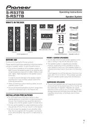
Checking the Standard Accessories<br />
Check to make sure that you have all the standard accessories before assembly and installation.<br />
Base cover x 1<br />
Stand pipes<br />
(left and right, interchangeable) x 2<br />
Light-blocking shield x 1<br />
Hexagonal wrench x 1<br />
(Opposite side 6 mm for M8 use)<br />
English<br />
Screws (4 mm x 10 mm) x 4<br />
Operating instructions<br />
(this document) x 1<br />
Installation bolts 1<br />
(M8 x 20 mm: black) x 2<br />
Installation bolts 2<br />
(M8 x 40 mm: black) x 2<br />
Attaching the Light-blocking Shield<br />
This part prevents reflection of the cables connected to the<br />
back of the Plasma Display on the base cover.<br />
Note<br />
Attach it after anchoring the base cover on a flat stable<br />
place.<br />
Light-blocking shield<br />
Attachment Procedure<br />
1 Remove the double-sided adhesive tape<br />
from the light-blocking shield.<br />
Remove each double-sided<br />
adhesive tape.<br />
Base cover<br />
9<br />
En
Attaching the Light-blocking Shield<br />
2 While firmly holding the ends of the lightblocking<br />
shield, apply it with the doublesided<br />
adhesive tape.<br />
3 Anchor it in place while pressing it down<br />
from above.<br />
Press<br />
Press<br />
Be sure that there<br />
is no gap.<br />
Note<br />
Be careful that the light-blocking shield does not catch on<br />
the pipe insertion holes.<br />
Anchor it in place so that there are no gaps (See diagram<br />
at right). If there is a gap, the light-blocking shield may<br />
peel off.<br />
Assembling the Stand<br />
Assembly Procedure<br />
1 Turn the base cover over so the underside<br />
is facing up.<br />
Note<br />
When the base cover is turned over, be very careful not<br />
to scratch or damage the light-blocking shield.<br />
2 Insert the stand pipes into the base cover.<br />
3 Tighten the screws to stabilize the stand<br />
pipes.<br />
Note<br />
Assemble the stand with a soft sheet placed under the base<br />
cover.<br />
If a sheet is not laid before assembly, the front surface of the<br />
base cover may be scratched.<br />
Screws<br />
(4 mm x 10 mm)<br />
Stand pipe<br />
Screws<br />
(4 mm x 10 mm)<br />
Stand pipe<br />
Base cover<br />
10<br />
En<br />
Sheet
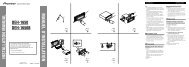
Attaching the Plasma Display<br />
Caution<br />
The weight of a Plasma Display is about 40 kg (88 lbs), they<br />
have no depth, and are unstable. Therefore, at least two<br />
people must assemble and install them.<br />
7 Regarding the stand pipe screw holes when the<br />
stand is used as a desktop stand<br />
Please use A and A’ in the following diagram.<br />
A<br />
Note<br />
Insert the bolts in the holes vertically.<br />
Place a sheet or protective cover to protect the display<br />
from scratches or damage.<br />
Assemble only with the Plasma Display lying flat on a<br />
table or similar surface.<br />
Move the stand so that the stand screw holes and the nuts<br />
that connect the main display line up correctly.<br />
A´<br />
A<br />
A´<br />
English<br />
1 With the Plasma Display lying flat, insert<br />
and secure the two Installation bolts 1<br />
(M8 x 20 mm: black) in the holes "a"<br />
located in center of the Plasma Display<br />
housing.<br />
At this point, tighten these bolts 1 only until the<br />
threads are no longer visible when viewed from the side<br />
(you will be unable to attach the display if the bolts are<br />
screwed in completely).<br />
Installation<br />
bolt 1<br />
Plasma Display<br />
housing<br />
Stop screwing<br />
down the bolt<br />
when the threads<br />
are no longer<br />
visible.<br />
Installation bolt 1<br />
(M8 x 20 mm: black)<br />
Holes "a"<br />
(holes in center<br />
of Plasma<br />
Display)<br />
2 As shown in the above diagram, hook the<br />
stand pipe holes A onto the screw heads<br />
of the installation bolts 1, then slide the<br />
stand upwards to the main Plasma Display<br />
until it engages the installation bolts 1.<br />
3 Pass the installation bolts 2 (M8 x 40 mm:<br />
black) through the stand pipe holes A’,<br />
and then screw them into the main<br />
Plasma Display with the accessory<br />
hexagonal wrench.<br />
Be sure to tighten the bolts securely.<br />
4 Tighten the installation bolts 1 firmly<br />
with the accessory hexagonal wrench.<br />
Be sure to tighten the bolts securely.<br />
Installation bolts 2<br />
(M8 x 40 mm: black)<br />
(Step 3)<br />
Slide the stand<br />
(Step 2)<br />
Plasma Display<br />
Sheet<br />
Note<br />
When laying down the Plasma Display, be careful so as to<br />
not scratch or damage it.<br />
Table top stand<br />
Table top stand<br />
Light-blocking<br />
shield<br />
Plasma Display<br />
Note<br />
Attach the Plasma Display so the light-blocking shield<br />
touches the bottom of its back surface.<br />
To install it in a rack etc. see Page 13.<br />
11<br />
En
Preventing Equipment from Falling Over<br />
After installing the stand, be sure to take special care to ensure that the equipment will not fall over.<br />
Stabilizing on table<br />
Stabilize the equipment as shown in the diagram using<br />
screws that are available on the market.<br />
Note<br />
To stabilize the equipment on a<br />
table, use screws that have a<br />
nominal diameter of 6 mm (1/4<br />
inch) and that are at least 20 mm<br />
(13/16 inch) long.<br />
9 mm to 15 mm<br />
(3/8 inch to 5/8 inch)<br />
Min. 20 mm<br />
(13/16 inch)<br />
6 mm<br />
(1/4 inch)<br />
Using a wall for stabilization<br />
1 Attaching falling prevention bolts (hooks)<br />
to the Plasma Display.<br />
2 Using strong cords to firmly stabilize it<br />
appropriately and firmly to a wall, pillar, or<br />
other sturdy element.<br />
Perform this work in the same way on the left and right<br />
sides.<br />
Note<br />
Use hooks, cords, and fittings that<br />
are available on the market.<br />
Recommended hook:<br />
12 mm to 15 mm<br />
Nominal diameter M8<br />
(1/2 inch to 5/8 inch)<br />
Length 12 mm to 15 mm (1/2 inch to 5/8 inch)<br />
M8<br />
1 Hook<br />
2 Cord<br />
Fitting<br />
Position of screws<br />
When stabilizing the stand to a table, use nominal<br />
diameter 6 mm (1/4 inch) with a length above<br />
20 mm (13/16 inch).<br />
Unit: mm (inch)<br />
120<br />
(4-23/32)<br />
Side View<br />
581<br />
(22-7/8)<br />
11 (13/32)<br />
301 (11-27/32) 29 (1-1/8)<br />
Caution<br />
• A table or an area of the floor with adequate strength<br />
should always be used to support the Plasma<br />
Display.<br />
Failure to do so could result in personal injury and<br />
physical damage.<br />
• When installing the Plasma Display, please take the<br />
necessary safety measures to prevent it from falling<br />
or overturning in case of emergencies, such as<br />
earthquakes, or of accidents.<br />
• If you do not take these precautions, the Plasma<br />
Display could fall down and cause injury.<br />
• The screws, hooks, chains and other fittings that you<br />
use to secure the Plasma Display to prevent it from<br />
overturning will vary according to the composition<br />
and thickness of the surface to which it will be<br />
attached.<br />
• Select the appropriate screws, hooks, chains and<br />
other fittings after first inspecting the surface<br />
carefully to determine its thickness and composition<br />
and after consulting a professional installer if<br />
necessary.<br />
12<br />
En
Installing the Product on a Rack etc.<br />
Caution<br />
When installing on a rack, etc., please be sure that the Plasma Display is held by two people.<br />
How to hold the Plasma Display<br />
When holding the<br />
Plasma Display<br />
erect:<br />
When laying down<br />
the Plasma Display:<br />
English<br />
Specifications<br />
External dimensions<br />
Weight<br />
576 mm (W) x 491 mm (H) x 335 mm (D) (22-11/16 in. (W) x 19-5/16 in. (H) x 13-3/16 in. (D))<br />
5.9 kg (13.0 lbs)<br />
• The above specifications and exterior may be modified without prior notice to improve the product.<br />
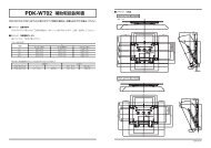
Dimensions Diagram<br />
Unit: mm (inch)<br />
1282 (50-1/2)<br />
123.1<br />
(4-27/32)<br />
750.5<br />
(29-9/16)<br />
150.5<br />
(5-15/16)<br />
289.5<br />
(11-13/32)<br />
815.5 (32-1/8)<br />
491 (19-5/16)<br />
62.5<br />
(2-15/32)<br />
25 (1)<br />
65<br />
(2-9/16)<br />
576 (22-11/16)<br />
149.4<br />
(5-7/8)<br />
335 (13-3/16)<br />
Published by <strong>Pioneer</strong> Corporation.<br />
Copyright © 2006 <strong>Pioneer</strong> Corporation.<br />
All rights reserved.<br />
13<br />
En
Nous vous remercions d’avoir choisi un produit <strong>Pioneer</strong>.<br />
Veuillez lire attentivement ce mode d’emploi pour savoir<br />
comment utiliser votre support correctement et en toute<br />
sécurité. Nous vous conseillons de conserver<br />
soigneusement ce mode d’emploi à portée de main et<br />
dans un endroit sûr afin de pouvoir vous y référer le cas<br />
échéant.<br />
Installation<br />
En cas de difficultés, veuillez consulter votre<br />
revendeur.<br />
<strong>Pioneer</strong> ne saurait être tenu responsable d’aucun<br />
dommage résultant d’une installation ou d’une<br />
utilisation incorrecte de ce produit, de sa modification<br />
ou encore de catastrophes naturelles.<br />
AVIS IMPORTANT<br />
Veuillez prendre note du numéro du modèle et du numéro<br />
de série de cet équipement ci-dessous.<br />
N° du modèle. <strong>PDK</strong>-<strong>TS23</strong> N° de série.<br />
Conservez ces numéros pour pouvoir les utiliser<br />
ultérieurement.<br />
Table des matières<br />
Attention ................................................................ 14<br />
Vérification des pièces fournies........................... 15<br />
Mise en place de l’écran occultant ...................... 15<br />
Assemblage du support ....................................... 16<br />
Fixation de l’écran à plasma ................................ 17<br />
Prévenir toute chute de l’équipement ................ 18<br />
Installation du produit sur une étagère, etc. ...... 19<br />
Caractéristiques techniques................................. 19<br />
Schéma de dimensions ........................................ 19<br />
ATTENTION<br />
Ce symbole indique un danger ou une pratique<br />
dangereuse susceptible de provoquer des dommages<br />
corporels ou matériels.<br />
Attention<br />
Ce produit est un pied de table conçu exclusivement pour<br />
les écrans à plasma (PDP-5000EX / PRO-FHD1) de marque<br />
<strong>Pioneer</strong>.<br />
L’utilisation de ce produit avec un autre modèle peut être à<br />
l’origine d’un manque de stabilité pouvant provoquer une<br />
blessure. Pour de plus amples informations, veuillez<br />
contacter le magasin où vous avez acheté votre écran.<br />
Ne procédez en aucun cas à installer ou à modifier le<br />
produit autrement qu’en suivant les indications fournies.<br />
En outre, n’utilisez pas ce support pour un écran à plasma<br />
autre que celui pour lequel il a été conçu et ne le modifiez<br />
pas ou ne l’utilisez pas à des fins autres que celles pour<br />
lesquelles il a été conçu.<br />
Une installation incorrecte est extrêmement dangereuse<br />
car elle peut provoquer la chute du support ou tout autre<br />
accident.<br />
Lieu d’installation<br />
• Sélectionnez un emplacement assez solide pour supporter<br />
le poids du support et de l’écran.<br />
• Assurez-vous de placer le produit à un emplacement<br />
stable et plat.<br />
• N’installez pas le support à l’extérieur, à proximité d’une<br />
source thermale ou sur une plage.<br />
• N’installez pas le support à un endroit où il pourrait être<br />
soumis à des chocs ou à des vibrations.<br />
Montage et installation<br />
• Montez le support en suivant les instructions et<br />
vissez solidement toutes les vis aux endroits prévus à<br />
cet effet.<br />
Des accidents ont été constatés (casse, chute du<br />
matériel, etc.) suite à l’installation de l’écran parce<br />
que le support n’avait pas été installé conformément<br />
aux instructions.<br />
• Pour une bonne installation, l’écran doit toujours être<br />
installé par au moins deux personnes.<br />
• Avant de procéder à l’installation, mettez l’écran ainsi<br />
que les équipements périphériques hors tension en<br />
coupant l’alimentation, puis retirez la prise du câble<br />
d’alimentation de la prise murale.<br />
Prévenez les accidents causés par la chute du produit<br />
en prenant des mesures fiables visant à éviter toute chute<br />
(voir Page 18).<br />
14<br />
Fr
Vérification des pièces fournies<br />
Veuillez vous assurer que vous possédez bien toutes les pièces nécessaires avant de procéder au montage et à l’installation<br />
du support.<br />
Couverture de table x 1 unité<br />
Colonnes de support<br />
(gauche et droite, interchangeables) x 2 unités<br />
Ecran occultant x 1<br />
Vis (4 mm x 10 mm) x 4 unités<br />
Clé hexagonale x 1 unité<br />
(Taille en diagonale 6 mm pour<br />
utilisation M8)<br />
Français<br />
Mode d’emploi<br />
(ce document) x 1 exemplaire<br />
Boulons d’installation 1<br />
(M8 x 20 mm : noir) x 2 unités<br />
Boulons d’installation 2<br />
(M8 x 40 mm : noir) x 2 unités<br />
Mise en place de l’écran occultant<br />
Il empêche que les câbles branchés au dos de l’écran à<br />
plasma ne se reflètent sur la couverture de table.<br />
Remarque<br />
Installez-le une fois que vous avez fixé la couverture de table<br />
sur une surface plane et stable.<br />
Ecran occultant<br />
Procédure d’installation<br />
1 Retirez le ruban adhésif double face qui se<br />
trouve sur l’écran occultant.<br />
Retirez le ruban adhésif<br />
double face.<br />
Couverture de table<br />
15<br />
Fr
Mise en place de l’écran occultant<br />
2 Tout en tenant fermement les extrémités<br />
de l’écran occultant, mettez-le en place à<br />
l’aide du ruban adhésif double face.<br />
3 Fixez-le en appuyant sur le dessus.<br />
Appuyez<br />
Appuyez<br />
Veillez à ce qu’il n’y ait<br />
pas d’espace libre.<br />
Remarque<br />
Veillez à ce que l’écran occultant ne déborde pas sur les<br />
trous d’insertion.<br />
Mettez-le en place de façon à ce qu’il n’y ait pas d’espace<br />
libre (cf. schéma de droite). S’il y avait un espace libre,<br />
l’écran pourrait se décoller.<br />
Assemblage du support<br />
Procédure de montage<br />
Vis<br />
(4 mm x 10 mm)<br />
1 Tournez le support de couverture de table<br />
de façon à ce que le dessous regarde vers<br />
le haut.<br />
Remarque<br />
Veillez à ne pas endommager ni érafler l’écran occultant<br />
lorsque la couverture de table est sur l’envers.<br />
2 Insérez les colonnes de support dans le<br />
support de couverture de table.<br />
3 Serrez les vis afin de stabiliser les<br />
colonnes de support.<br />
Remarque<br />
Avant de monter le support, glissez un drap doux sous la<br />
couverture de table. Sans ce drap, vous risqueriez d’érafler la<br />
surface de la couverture de table.<br />
Colonne de<br />
support<br />
Vis<br />
(4 mm x 10 mm)<br />
Colonne de<br />
support<br />
Couverture de table<br />
16<br />
Fr<br />
Drap
Fixation de l’écran à plasma<br />
Attention<br />
Un écran à plasma pèse environ 40 kg. La largeur de ce<br />
type d’écran étant limitée, ils ne sont pas stables.<br />
Par conséquent, ils doivent toujours être assemblés et<br />
installés par deux personnes à la fois.<br />
7 Prise en compte des fentes de la colonne de<br />
support lorsque le support est utilisé comme<br />
support de bureau<br />
Reportez-vous au A et A’ du schéma suivant.<br />
A<br />
Remarque<br />
Introduisez les boulons dans les trous à la verticale.<br />
Placez une drap ou une bâche afin de protéger l’écran des<br />
éraflures ou autres détériorations.<br />
Montez toujours l’écran à plasma sur une surface plane et<br />
stable uniquement.<br />
Déplacez le support de manière à ce que les fentes du<br />
support destinées à recevoir les vis et les boulons qui<br />
raccordent l’écran principal soient parfaitement alignées.<br />
2 Une fois que l’écran à plasma est bien à<br />
plat, veuillez insérer et fixer les deux<br />
boulons d’installation 1 (M8 x 20 mm :<br />
noir) dans les fentes "a" placées au centre<br />
du boîtier de l’écran à plasma.<br />
Puis, serrez les vis 1 jusqu’à ce que les filets ne soient<br />
plus visibles quand vous regardez de côté (il vous sera<br />
impossible de fixer l’écran à plasma si ces vis sont<br />
complètement vissées dans les fentes).<br />
Boulons<br />
d’installation 1<br />
Boîtier de<br />
l’écran à plasma<br />
Cessez de visser<br />
davantage les<br />
boulons dès que<br />
les filets ne sont<br />
plus visibles.<br />
Boulons<br />
d’installation 1<br />
(M8 x 20 mm : noir)<br />
Fentes "a"<br />
(fentes dans le<br />
centre de l’écran<br />
à plasma)<br />
A´<br />
2 Comme indiqué sur le schéma ci-dessus,<br />
placez les trous de la colonne de support A<br />
sur les têtes des boulons d’installation 1,<br />
puis faites glisser le support vers le haut<br />
dans l’écran à plasma principal jusqu’à<br />
engagement des boulons d’installation 1.<br />
3 Glissez les boulons d’installation 2 (M8 x<br />
40 mm : noir) dans les trous A’ de la<br />
colonne de support et vissez-les dans<br />
l’écran à plasma principal à l’aide de la clé<br />
hexagonale fournie.<br />
Veillez à bien serrer les boulons.<br />
4 Serrez les boulons d’installation 1<br />
fermement au moyen de la clé hexagonale<br />
fournie.<br />
Veillez à bien serrer les boulons.<br />
A<br />
A´<br />
Boulons<br />
d’installation 2<br />
(M8 x 40 mm : noir)<br />
(Étape 3)<br />
Français<br />
Faites glisser le support<br />
(Étape 2)<br />
Écran à plasma<br />
Drap<br />
Remarque<br />
Veillez à ne pas érafler l’écran plasma ni l’endommager<br />
lorsque vous le couchez.<br />
Pied de table<br />
Pied de table<br />
Ecran occultant<br />
Écran à plasma<br />
Remarque<br />
Installez l’écran à plasma de façon à ce que l’écran<br />
occultant touche le bas de sa surface arrière.<br />
Pour installer l’écran à plasma sur une étagère, voir Page 19.<br />
17<br />
Fr
Prévenir toute chute de l’équipement<br />
Après avoir installé le support, veillez à prendre les précautions nécessaires pour qu’il ne tombe pas.<br />
Stabilisation sur une table<br />
Stabilisez le support comme indiqué sur le schéma à l’aide<br />
de vis vendues dans le commerce.<br />
Remarque<br />
Pour stabiliser l’équipement sur<br />
une table, utilisez des vis 6 mm<br />
d’au moins 20 mm de long.<br />
9 mm à 15 mm<br />
Min. 20 mm<br />
6 mm<br />
Utilisation d’un mur pour stabiliser le support<br />
1 Fixation des boulons empêchant la chute<br />
(crochets) sur l’écran à plasma.<br />
2 Utilisation de câbles solides pour stabiliser<br />
le dispositif contre un mur, un pilier ou<br />
tout autre élément stable, avec fermeté et<br />
de façon appropriée.<br />
Ces opérations doivent être effectuées de la même<br />
manière à gauche et à droite.<br />
Remarque<br />
Utilisez des crochets, des câbles et<br />
d’autres dispositifs de fixation en<br />
vente dans le commerce.<br />
Crochet recommandé : Diamètre<br />
nominal M8, longueur de 12 mm à 15 mm.<br />
M8<br />
12 mm à 15 mm<br />
1 Crochet<br />
2 Câble<br />
Position des vis<br />
Pour stabiliser le support sur une table, utilisez des vis 6<br />
mm d’au moins 20 mm de long.<br />
Unité : mm<br />
Attache<br />
120 581<br />
Vue latérale<br />
11<br />
301 29<br />
Attention<br />
• Choisissez toujours une table ou une portion du sol<br />
avec une force suffisante pour supporter l’écran<br />
plasma. Il en résulterait autrement des blessures<br />
corporelles et des dégâts physiques.<br />
• Lors de l’installation de l’écran plasma, veuillez<br />
prendre les mesures de sécurité nécessaires pour<br />
l’empêcher de tomber ou de basculer en cas de<br />
sinistres comme un tremblement de terre ou un<br />
accident.<br />
• Le cas contraire, l’écran plasma pourrait tomber et<br />
provoquer des dégâts.<br />
• Les vis, crochets, chaînes et autres raccords que<br />
vous utilisez pour fixer en place l’écran plasma afin<br />
de l’empêcher de basculer dépendront de la<br />
composition et de l’épaisseur de la surface sur<br />
laquelle vous le fixez.<br />
• Choisissez les vis, crochets, chaînes et autres<br />
raccords appropriés après avoir tout d’abord<br />
soigneusement inspecter la surface pour déterminer<br />
sa composition et son épaisseur et après avoir pris<br />
contact avec un installateur professionnel si besoin<br />
est.<br />
18<br />
Fr
Installation du produit sur une étagère, etc.<br />
Attention<br />
En cas d’installation de l’écran sur une étagère, etc., veillez à ce qu’il soit maintenu par deux<br />
personnes.<br />
Comment tenir l’écran à plasma<br />
Lorsque vous tenez<br />
l’écran à plasma<br />
droit :<br />
Lorsque vous<br />
couchez l’écran à<br />
plasma :<br />
Français<br />
Caractéristiques techniques<br />
Dimensions extérieures<br />
Poids<br />
576 mm (largeur) x 491 mm (hauteur) x 335 mm (profondeur)<br />
5,9 kg<br />
• Les caractéristiques techniques indiquées ci-dessus ainsi que les dimensions extérieures peuvent êtres modifiées sans<br />
préavis en vue d’améliorer le produit.<br />
Schéma de dimensions<br />
Unité : mm<br />
1282<br />
123,1<br />
750,5<br />
150,5<br />
815,5<br />
289,5<br />
491<br />
62,5<br />
25<br />
65<br />
576<br />
335<br />
149,4<br />
Publication de <strong>Pioneer</strong> Corporation.<br />
© 2006 <strong>Pioneer</strong> Corporation.<br />
Tous droits de reproduction et de traduction réservés.<br />
19<br />
Fr
Wir danken Ihnen, dass Sie sich für den Kauf dieses<br />
Produkts der Firma <strong>Pioneer</strong> entschieden haben.<br />
Bitte lesen Sie die Bedienungsanleitung aufmerksam, um<br />
sich damit vertraut zu machen, Ihr Modell richtig und sicher<br />
zu handhaben.<br />
Wir empfehlen Ihnen, die Bedienungsanleitung gut<br />
aufzubewahren, um sie künftig im Bedarfsfalle jederzeit zu<br />
Rate ziehen zu können.<br />
Installation<br />
Sollten Sie bei der Installation irgendwelche<br />
Schwierigkeiten haben, dann wenden Sie sich bitte an<br />
Ihren Händler.<br />
Für Schäden aufgrund von inkorrekter Installation,<br />
falscher Verwendung, vorgenommenen<br />
Veränderungen oder Naturkatastrophen übernimmt<br />
<strong>Pioneer</strong> keine Verantwortung.<br />
Wichtiger Hinweis!<br />
Bitte notieren Sie sich unten die Nummer des Modells<br />
und die Serien-Nummer des Geräts.<br />
Modell: <strong>PDK</strong>-<strong>TS23</strong> Serien-Nummer:<br />
Bewahren Sie diese Angaben für den künftigen<br />
Gebrauch.<br />
Inhalt<br />
Sicherheitshinweise.............................................. 20<br />
Überprüfung des Standardzubehörs auf<br />
Vollständigkeit ...................................................... 21<br />
Befestigen der Reflexionsschutz-Leiste .............. 21<br />
Montage des Tischständers ................................. 22<br />
Montage des Plasmadisplays .............................. 23<br />
Verhinderung eines möglichen Umfallens der<br />
Einheit .................................................................... 24<br />
Installation des Plasmadisplays an einem<br />
Gestell usw. ........................................................... 25<br />
Technische Daten .................................................. 25<br />
Darstellung der Abmessungen ............................ 25<br />
Vorsicht!<br />
Dieses Symbol kennzeichnet eine gefährliche oder<br />
unsichere Handlungsweise, die zu einem Unfall mit<br />
Verletzung oder zu Sachschäden führen kann.<br />
Sicherheitshinweise<br />
Dieses Produkt ist ein Tischständer, der ausschließlich für<br />
Plasmadisplay (PDP-5000EX) der Firma <strong>Pioneer</strong> vorgesehen<br />
ist. Die Verwendung des Tischständers für ein anderes<br />
Modell führt möglicherweise zu einer Instabilität und kann<br />
demzufolge Unfälle mit Verletzungen verursachen.<br />
Hinsichtlich weiterer Informationen wenden Sie sich bitte<br />
an diejenige Handelseinrichtung, bei der Sie das<br />
Plasmadisplay gekauft haben.<br />
Installieren Sie das Produkt nicht anders als angegeben und<br />
nehmen Sie keine Veränderungen am Produkt vor.<br />
Verwenden Sie den Tischständer nicht für ein anderes<br />
Plasmadisplay als für die Modelle, für die er vorgesehen<br />
ist, nehmen Sie keine Veränderungen daran vor und<br />
verwenden Sie ihn nicht für andere Zwecke.<br />
Eine falsche Installation ist sehr gefährlich, da sie zum<br />
Umfallen der Einheit oder zu einem anderen Unfall führen<br />
kann.<br />
Installationsort<br />
• Wählen Sie für die Installation einen Platz, der stabil<br />
genug ist, das Gewicht des Tischständers und des<br />
Displays zu tragen.<br />
• Sorgen Sie dafür, dass der Ständer und das betreffende<br />
Display auf einem ebenen und stabilen Platz installiert<br />
werden.<br />
• Installieren Sie beides nicht im Freien, in der Nähe einer<br />
heißen Quelle oder in Strandnähe.<br />
• Installieren Sie die Einheit nicht an einem Platz, an dem<br />
sie möglicherweise Vibrationen oder Stößen ausgesetzt<br />
ist.<br />
Montage und Installation<br />
• Montieren Sie den Ständer gemäß den<br />
Montageanweisungen und befestigen Sie sorgfältig<br />
alle Schrauben an den dafür vorgesehenen<br />
Positionen.<br />
Es hat Fälle gegeben, dass es zu unvorhergesehenen<br />
Unfällen wie beispielsweise einer Havarie oder einem<br />
Umfallen der Einheit gekommen ist, weil der Ständer<br />
nicht gemäß den gegebenen Anweisungen installiert<br />
wurde.<br />
• Das Display muss immer von mindestens zwei<br />
Personen installiert werden, um zu sicherzugehen,<br />
dass es sicher installiert wird.<br />
• Schalten Sie das Display und die peripheren Geräte<br />
vor der Installation aus und ziehen Sie anschließend<br />
den Stecker der Netzschnur aus der Steckdose.<br />
Verhindern Sie Unfälle, die durch das Umfallen der Einheit<br />
verursacht werden, indem Sie geeignete Maßnahmen<br />
treffen, die dies ausschließen (siehe Seite 24).<br />
20<br />
Ge
Überprüfung des Standardzubehörs auf Vollständigkeit<br />
Überprüfen Sie vor Beginn der Montage und Installation, ob alle Teile des Standardzubehörs vorhanden sind.<br />
Basisabdeckung x 1<br />
Ständerelemente<br />
(links und rechts, austauschbar) x 2<br />
Reflexionsschutz-Leiste x 1<br />
Innensechskantschlüssel<br />
(Gegenseite 6 mm für M8-Verwendung) x 1<br />
Schrauben (4 mm x 10 mm) x 4<br />
Bedienungsanleitung<br />
(das vorliegende Dokument) x 1<br />
Installationsschrauben 1<br />
(M8 x 20 mm, schwarz) x 2<br />
Installationsschrauben 2<br />
(M8 x 40 mm, schwarz) x 2<br />
Deutsch<br />
Befestigen der Reflexionsschutz-Leiste<br />
Dieses Teil verhindert die Reflexion der Kabel, die an der<br />
Basis-Abdeckung an die Rückseite des Plasmadisplays<br />
angeschlossen sind.<br />
Hinweis<br />
Befestigen Sie die Leiste, nachdem Sie die Basisabdeckung<br />
an einem flachen und stabilen Ort verankert haben.<br />
Verfahrensweise der Befestigung<br />
1 Entfernen Sie das doppelseitig klebende<br />
Band von der Relexionsschutz-Leiste.<br />
Entfernen Sie jedes<br />
doppelseitig klebende Band.<br />
Reflexionsschutz-Leiste<br />
Basisabdeckung<br />
21<br />
Ge
Befestigen der Reflexionsschutz-Leiste<br />
2 Kleben Sie, während Sie die Enden der<br />
Reflexionsschutz-Leiste festhalten, das<br />
doppelseitig klebende Band darauf.<br />
3 Fixieren Sie die Leiste an der<br />
vorgesehenen Stelle durch Drücken von<br />
oben.<br />
Drücken<br />
Hinweis<br />
Achten Sie bitte darauf, dass die Reflexionsschutz-Leiste<br />
nicht auf die Einführungs-Öffnungen für die<br />
Ständerelemente gelangt.<br />
Nehmen Sie die Befestigung an der betreffenden Position<br />
so vor, dass es keine Lücken gibt (siehe Abbildung rechts).<br />
Wenn eine Lücke bleibt, kann es sein, dass sich die<br />
Reflexionsschutz-Leiste löst.<br />
Drücken<br />
Bitte darauf achten,<br />
dass keine Lücke<br />
vorhanden ist.<br />
Montage des Tischständers<br />
Montage<br />
Schrauben<br />
(4 mm x 10 mm)<br />
1 Drehen Sie die Basisabdeckung um, so<br />
dass die Unterseite nach oben zeigt.<br />
Schrauben<br />
(4 mm x 10 mm)<br />
Hinweis<br />
Achten Sie bitte darauf, beim Umlegen der<br />
Basisabdeckung die Reflexionsschutz-Leiste nicht zu<br />
zerkratzen oder zu beschädigen.<br />
2 Führen Sie Ständerelemente in die<br />
Basisabdeckung ein.<br />
3 Ziehen Sie die Schrauben fest an, um die<br />
Ständerelemente zu stabilisieren.<br />
Hinweis<br />
Montieren Sie den Ständer, indem Sie ein weiches Tuch<br />
unter die Basisabdeckung legen.<br />
Wenn Sie das nicht tun, ist es möglich, dass die vordere<br />
Oberfläche zerkratzt wird.<br />
Ständerelement<br />
Ständerelement<br />
Basisabdeckung<br />
22<br />
Ge<br />
Tuch
Montage des Plasmadisplays<br />
Vorsicht!<br />
Das Plasmasdisplay wiegt etwa 40 kg. Es weist keine Tiefe<br />
auf und ist somit instabil. Deshalb muss die Montage und<br />
Installation eines Plasmadisplays von mindestens zwei<br />
Personen vorgenommen werden.<br />
7 Die Schraublöcher der Ständerelemente bei<br />
Verwendung des Ständers als Plasmadisplay-<br />
Tischständer<br />
Bitte verwenden Sie A und A’, wie sie in der folgenden<br />
Abbildung dargestellt sind.<br />
A<br />
Hinweis<br />
Führen Sie die Schrauben vertikal in die Öffnungen ein.<br />
Legen Sie ein Tuch, eine Decke oder eine Schutzabdeckung<br />
unter das Display, um es vor Kratzern oder sonstigen<br />
Schäden zu schützen.<br />
Nehmen Sie die Montage nur vor, indem Sie das<br />
Plasmadisplay flach auf eine Tisch oder eine ähnliche<br />
Unterlage legen.<br />
Bewegen Sie den Tischständer so, dass seine<br />
Schraublöcher und die Muttern zum Anschluss des<br />
Displays richtig ausgerichtet sind.<br />
1 Führen Sie bei flach liegendem<br />
Plasmadisplay die zwei<br />
Installationsschrauben 1 (M8 x 20 mm,<br />
schwarz) in die in der Mitte des<br />
Plasmadisplay-Gehäuse befindlichen<br />
Schraublöcher „a“ ein und schrauben Sie<br />
sie ein.<br />
Ziehen Sie jetzt diese Schrauben 1 nur so weit fest, bis<br />
die Gewindegänge beim seitlichen Anblick nicht mehr<br />
sichtbar sind (bei einem vollständigen Einschrauben der<br />
Schrauben ist es nicht möglich, das Display zu<br />
montieren).<br />
Installationsschrauben 1<br />
Plasmadisplay-<br />
Gehäuse<br />
Schrauben Sie<br />
nicht weiter, wenn<br />
die Gewindegänge<br />
der Schrauben<br />
nicht mehr<br />
sichtbar sind.<br />
Installationsschrauben 1<br />
(M8 x 20 mm, schwarz)<br />
A´<br />
2 Bringen Sie die Schraubenköpfe der<br />
Installationsschrauben 1 in die in der obigen<br />
Zeichnung dargestellten Schrauböffnungen A<br />
und schieben Sie daraufhin den Tischständer<br />
nach oben zum Plasmadisplay bis zum<br />
Einrasten der Installationsschrauben 1.<br />
3 Führen Sie die Installationsschrauben 2 (M8 x<br />
40 mm, schwarz) in die Öffnungen A’ der<br />
Ständerelemente des Tischständers ein und<br />
ziehen Sie sie mit dem als Zubehör<br />
mitgelieferten Innensechskantschlüssel fest.<br />
Ziehen Sie die Schrauben fest an.<br />
4 Ziehen Sie die Installationsschrauben 1 mit<br />
dem als Zubehör mitgelieferten<br />
Innensechskantschlüssel fest.<br />
Ziehen Sie die Schrauben fest an.<br />
A<br />
A´<br />
Installationsschrauben 2<br />
(M8 x 40 mm, schwarz)<br />
(Schritt 3)<br />
Deutsch<br />
Schraublöcher<br />
„a“ (Öffnungen<br />
in der Mitte des<br />
Plasmadisplays)<br />
Verschieben des<br />
Tischständers (Schritt 2)<br />
Plasmadisplay<br />
Tuch<br />
Tischständer<br />
Tischständer<br />
Reflexionsschutz-<br />
Leiste<br />
Hinweis<br />
Vorsicht beim Hinlegen des Plasmadisplays, damit Sie es<br />
nicht zerkratzen oder anderweitig beschädigen.<br />
Plasmadisplay<br />
Hinweis<br />
Befestigen Sie das Plasmadisplay so, dass die<br />
Rflexionsschutzleiste den Boden an seiner Rückseite<br />
berührt.<br />
Zur Installation in einem Gestell siehe Seite 25.<br />
23<br />
Ge
Verhinderung eines möglichen Umfallens der Einheit<br />
Verwenden Sie bei der Installation des Tischständers besonderes Augenmerk darauf, zu verhindern,<br />
dass die Einheit umfallen kann.<br />
Stabilisierung auf dem Tisch<br />
Stabilisieren Sie die Einheit unter Verwendung<br />
handelsüblicher Schrauben, wie im Bild dargestellt.<br />
Hinweis<br />
Verwenden Sie zur Stabilisierung<br />
der Einheit auf einem Tisch nur<br />
Schrauben, die einen<br />
Nenndurchmesser von 6 mm<br />
haben und die mindestens 20 mm<br />
lang sind.<br />
9 mm bis 15 mm<br />
Mind. 20 mm<br />
6 mm<br />
Verwendung einer Wand zur Stabilisierung<br />
1 Montage von Schrauben (Haken) an das<br />
Plasmadisplay zur Verhinderung des<br />
Umfallens.<br />
2 Verwendung von reißfesten Schnuren zur<br />
ausreichenden und sicheren Stabilisierung<br />
an einer Wand, einem Pfeiler oder einem<br />
anderen stabilen Bauelement.<br />
Führen Sie diese Arbeiten in der gleichen Weise auf der<br />
linken und der rechten Seite aus.<br />
Hinweis<br />
Verwenden Sie handelsübliche<br />
Halteschrauben, Schnuren und Haken.<br />
Empfohlene Halteschrauben:<br />
Nenndurchmesser M8<br />
Länge 12 mm bis 15 mm<br />
M8<br />
12 mm bis 15 mm<br />
Haken<br />
1 Halteschraube<br />
2 Schnur<br />
24<br />
Ge<br />
Position der Schrauben<br />
Verwenden Sie zur Stabilisierung der Einheit auf einem<br />
Tisch nur Schrauben mit einem Nenndurchmesser von<br />
6 mm und einer Länge von über 20 mm.<br />
Einheit: mm<br />
120 581<br />
Seitenansicht<br />
11<br />
301 29<br />
Vorsicht!<br />
• Für das Plasmadisplay muss ein ausreichend stabiler<br />
Tisch oder eine entsprechende Bodenfläche gewählt<br />
werden. Geschieht das nicht, könnte es zu einem<br />
Unfall mit Verletzungen oder mit Sachschaden<br />
kommen.<br />
• Bitte treffen Sie die nötigen Vorsichtsmaßnahmen<br />
zur Verhinderung des Fallens oder Umkippens im<br />
Falle von Gefahren wie beispielsweise Erdbeben<br />
oder von Unfällen.<br />
• Wenn Sie diese Vorsichtsmaßnahmen nicht treffen,<br />
könnte das Plasmadisplay herunterfallen oder<br />
umfallen und so zu einem Unfall mit Verletzungen<br />
führen.<br />
• Die Schrauben, Halteschrauben, Ketten und Haken,<br />
die Sie zur Sicherung des Plasmadisplays<br />
verwenden, um es vor dem Umfallen zu bewahren,<br />
können je nach dem Aufbau und der Dicke der<br />
Fläche, auf der es montiert wird, variieren.<br />
• Wählen Sie die jeweils geeigneten Schrauben,<br />
Halteschrauben, Ketten und Haken, nachdem Sie<br />
sich zunächst die vorgesehene Fläche genau<br />
angesehen haben, um ihre Dicke und ihren Aufbau<br />
zu beurteilen, und nachdem Sie, wenn erforderlich,<br />
einen Fachmann konsultiert haben.
Installation des Plasmadisplays an einem Gestell usw.<br />
Vorsicht!<br />
Bitte achten Sie darauf, dass das Plasmadisplay bei der Installation an einem Gestell usw. von zwei<br />
Personen gehalten wird.<br />
Handhabung des Plasmadisplays<br />
Halten des<br />
Plasmadisplays in<br />
aufrechter Stellung:<br />
Halten beim<br />
Niederlegen des<br />
Plasmadisplays:<br />
Deutsch<br />
Technische Daten<br />
Außenabmessungen<br />
Gewicht<br />
576 mm (Breite) x 491 mm (Höhe) x 335 mm (Tiefe)<br />
5,9 kg<br />
• Die obigen technischen Daten und das Äußere können, um das Produkt zu verbessern, ohne vorherige Ankündigung<br />
verändert werden.<br />
Darstellung der Abmessungen<br />
Einheit: mm<br />
1282<br />
123,1<br />
491<br />
750,5<br />
150,5<br />
815,5<br />
289,5<br />
62,5<br />
25<br />
65<br />
576<br />
335<br />
149,4<br />
Veröffentlicht von <strong>Pioneer</strong> Corporation.<br />
Urheberrechtlich geschützt © 2006 <strong>Pioneer</strong> Corporation.<br />
Alle Rechte vorbehalten.<br />
25<br />
Ge
Grazie per aver acquistato un prodotto <strong>Pioneer</strong>.<br />
Per imparare ad usare il vostro modello in modo sicuro e<br />
corretto, leggete accuratamente le istruzioni per l’uso.<br />
Vi consigliamo di tenere le istruzioni per l’uso a portata di<br />
mano per future consultazioni.<br />
Installazione<br />
Se incontrate delle difficoltà durante l’installazione,<br />
rivolgetevi al vostro fornitore.<br />
<strong>Pioneer</strong> non è responsabile per qualsiasi danno<br />
causato da un’installazione non corretta, da un uso<br />
improprio, da modifiche o da calamità naturali.<br />
AVVISO IMPORTANTE<br />
Registrate il numero di modello e di serie<br />
dell’apparecchio qui sotto.<br />
Model N. <strong>PDK</strong>-<strong>TS23</strong> Serial No.<br />
Conservate questo numero per usarlo in seguito.<br />
Indice<br />
Attenzione ............................................................. 26<br />
Controllo degli accessori standard ...................... 27<br />
Fissaggio della protezione antiriflesso ............... 27<br />
Montaggio del supporto....................................... 28<br />
Fissaggio del display a plasma ............................ 29<br />
Prevenire la caduta dell’apparecchio .................. 30<br />
Montaggio del prodotto su uno scaffale, ecc. .... 31<br />
Dati tecnici ............................................................. 31<br />
Grafico delle misure .............................................. 31<br />
ATTENZIONE<br />
Questo simbolo si riferisce ad una procedura azzardata<br />
o pericolosa che può recare danni alle persone o alle<br />
cose.<br />
Attenzione<br />
Questo articolo è un supporto di tavolo, progettato<br />
esclusivamente per i display a plasma <strong>Pioneer</strong> (PDP-5000EX).<br />
L’uso con altri modelli può causare instabilità e provocare<br />
danni. Per ulteriori informazioni, contattate il negozio dove<br />
avete acquistato il Vostro display.<br />
Non installate o modificate il prodotto diversamente da<br />
come illustrato. Non usate un supporto per display a plasma<br />
diverso da quello progettato, e non modificatelo per altri<br />
scopi.<br />
Un’installazione non corretta è estremamente pericolosa<br />
perché potrebbere causare la caduta dell’apparecchio o altri<br />
incidenti.<br />
Posizione dell’installazione<br />
• Scegliete una posizione abbastanza resistente da<br />
sostenere i pesi del supporto e del display.<br />
• Assicuratevi di posizionarlo in piano e in modo stabile.<br />
• Non installatelo all’aperto, vicino a fonti di calore o a una<br />
spiaggia.<br />
• Non installate il supporto dove potrebbe essere esposto a<br />
vibrazioni o urti.<br />
Montaggio e installazione<br />
• Montate il supporto secondo le istruzioni di<br />
montaggio e fissate bene tutte le viti nelle posizioni<br />
predisposte.<br />
Dopo l’installazione del display, si possono verificare<br />
incidenti imprevisti, come la rottura o la caduta<br />
dell’apparecchio, se il supporto non è stato installato<br />
secondo le istruzioni.<br />
• Per garantire un’installazione sicura, il display deve<br />
essere montato sempre da due o più persone.<br />
• Prima dell’installazione, spegnete il display e le<br />
periferiche, poi disinserite la spina dalla presa di<br />
alimentazione.<br />
Per evitare incidenti causati dalla caduta del prodotto,<br />
prendete le necessarie precauzioni per impedire la sua<br />
caduta (vedi pagina 30).<br />
26<br />
It
Controllo degli accessori standard<br />
Prima del montaggio e dell’installazione controllate che tutti gli accessori standard siano stati forniti.<br />
Coperchio della base x 1 Gambe del supporto x 2<br />
(sinistra e destra, intercambiabili)<br />
Protezione antiriflesso x 1<br />
Chiave inglese x 1<br />
(lato opposto 6 mm per uso M8)<br />
Viti x 4 (4 mm x10 mm)<br />
Istruzioni per l’uso x 1<br />
(questo manuale)<br />
Bulloni di installazione 1 x 2<br />
(M8 x 20 mm, neri)<br />
Bulloni di installazione 2 x 2<br />
(M8 x 40 mm, neri)<br />
Italiano<br />
Fissaggio della protezione antiriflesso<br />
Questo pezzo impedisce la riflessione dei cavi collegati alla<br />
parte posteriore del display a plasma sul coperchio della<br />
base.<br />
Nota<br />
Fissatela dopo aver ancorato il coperchio della base su una<br />
superficie piana e stabile.<br />
Procedura di fissaggio<br />
1 Togliete il nastro biadesivo dalla<br />
protezione antiriflesso.<br />
Togliete tutto il nastro biadesivo.<br />
Protezione antiriflesso<br />
Coperchio della base<br />
27<br />
It
Fissaggio della protezione antiriflesso<br />
2 Tenendo ben ferme le estremità, fissate la<br />
protezione antiriflesso con il nastro<br />
biadesivo.<br />
3 Fissatela premendo la parte superiore<br />
verso il basso.<br />
Premete<br />
Premete<br />
Assicuratevi che non vi<br />
siano spazi vuoti.<br />
Nota<br />
Assicuratevi che la protezione antiriflesso non copra i fori<br />
di inserimento delle gambe del supporto.<br />
Fissatela in modo che non vi siano spazi vuoti (Vedi figura<br />
a destra). Altrimenti, la protezione antiriflesso potrebbe<br />
scollarsi.<br />
Montaggio del supporto<br />
Procedura di montaggio<br />
1 Girate il coperchio della base con la parte<br />
inferiore rivolta verso l’alto.<br />
Nota<br />
Quando fate ruotare il coperchio della base, fate<br />
attenzione a non graffiare o danneggiare la protezione<br />
antiriflesso.<br />
2 Inserite le gambe del supporto nel<br />
coperchio della base.<br />
3 Stringere le viti per bloccare le gambe del<br />
supporto.<br />
Nota<br />
Quando montate il supporto appoggiate un lenzuolo sotto il<br />
coperchio della base. Se non si appoggia il lenzuolo prima<br />
del montaggio, la superficie anteriore del coperchio della<br />
base potrebbe graffiarsi.<br />
Viti<br />
(4 mm x 10 mm)<br />
Gamba del<br />
supporto<br />
Viti<br />
(4 mm x 10 mm)<br />
Gamba del<br />
supporto<br />
Coperchio della base<br />
28<br />
It<br />
Lenzuolo
Fissaggio del display a plasma<br />
Attenzione<br />
Il peso del display a plasma è di circa 40 kg, non hanno<br />
profondità e sono instabili. Per questo motivo devono essere<br />
montati e installati da almeno due persone.<br />
7 Si riferisce ai fori per le viti della gamba del<br />
supporto, se il supporto viene usato come<br />
scrivania<br />
Usate A e A’ come mostrato nello schema qui sotto.<br />
A<br />
Nota<br />
Inserite verticalmente i bulloni nei fori.<br />
Stendete un lenzuolo o un telo per proteggere il display da<br />
graffi o danni.<br />
Montatelo solo quando il display a plasma si trova in<br />
posizione piana su un tavolo o su una superficie simile.<br />
Spostate il supporto in modo che i fori per le viti del<br />
supporto e i dadi per l’applicazione del display siano<br />
allineati correttamente.<br />
A´<br />
A<br />
A´<br />
1 Con il display a plasma in posizione<br />
orrizzontale, inserite e serrate i due bulloni<br />
di installazione 1 (M8 x 20 mm, neri) nei<br />
fori “a” posizionati al centro del<br />
contenitore del display a plasma.<br />
A questo punto, serrate i bulloni 1 solo fino a quando la<br />
filettatura non è più visibile dal lato (non si riuscirà a<br />
montare il display se i bulloni sono avvitati<br />
completamente).<br />
Bulloni di<br />
installazione 1<br />
Contenitore del<br />
display a plasma<br />
i bulloni sono<br />
completamente<br />
avvitati non<br />
appena la<br />
filettatura non è<br />
più visibile.<br />
Bulloni di<br />
installazione 1<br />
(M8 x 20 mm, neri)<br />
Fori “a”<br />
(fori al centro<br />
del display a<br />
plasma)<br />
2 Come mostrato nell’immagine sopra,<br />
agganciate i fori delle gambe del supporto<br />
A alle teste delle viti dei bulloni di<br />
installazione 1, poi fate scivolare il<br />
supporto verso l’alto fino al principale<br />
display a plasma, fino a quando si fissa ai<br />
bulloni di installazione 1.<br />
3 Inserite i bulloni di installazione 2 (M8 x<br />
40 mm: neri) attraverso i fori delle gambe<br />
del supporto A’, quindi avvitateli al display<br />
a plasma principale con chiave inglese in<br />
dotazione.<br />
Assicuratevi che i bulloni siano serrati saldamente.<br />
4 Serrate bene i bulloni di installazione 1<br />
usando l’accessorio chiave inglese.<br />
Assicuratevi che i bulloni siano serrati saldamente.<br />
Bulloni di installazione 2<br />
(M8 x 40 mm, neri)<br />
(passo 3)<br />
Italiano<br />
Display a plasma<br />
Fate slittare il supporto<br />
(passo 2)<br />
Lenzuolo<br />
Nota<br />
Quando appoggiate il Display a Plasma, fate attenzione a<br />
non graffiarlo o danneggiarlo.<br />
Supporto di tavolo<br />
Supporto di tavolo<br />
Protezione<br />
antiriflesso<br />
Display a plasma<br />
Nota<br />
Fissate il display a plasma in modo che la protezione<br />
antiriflesso combaci con la parte inferiore della superficie<br />
posteriore.<br />
Per il montaggio su uno scaffale, ecc. vedi Pagina 31.<br />
29<br />
It
Prevenire la caduta dell’apparecchio<br />
Dopo il montaggio del supporto, assicuratevi che l’apparecchio non sia in condizioni di cadere.<br />
Fissare su tavolo<br />
Fissare l’apparecchio usando delle viti disponibili sul<br />
mercato come mostrato nel grafico.<br />
Nota<br />
Per fissare l’apparecchio su un<br />
tavolo, usate viti con diametro<br />
nominale di 6 mm e lunghezza di<br />
almeno 20 mm.<br />
da 9 mm a 15 mm<br />
min. 20 mm<br />
6 mm<br />
Fissare l’apparecchio al muro<br />
1 Fissate i bulloni (ganci) al display a plasma<br />
per prevenire la caduta.<br />
2 Usate corde robuste per fissarlo bene e<br />
con cura a un muro, pilastro o altro<br />
elemento resistente.<br />
Svolgete questo lavoro nello stesso modo sul lato<br />
sinistro e su quello destro.<br />
Nota<br />
Usate ganci, corde e accessori che si<br />
trovano sul mercato.<br />
Gancio consigliato:<br />
Diametro nominale M8<br />
Lunghezza da 12 mm a 15 mm<br />
M8<br />
da 12 mm a 15 mm<br />
2 Corda<br />
1 Gancio<br />
Posizione delle viti<br />
Per fissare il supporto su un tavolo, usate viti con<br />
diametro nominale di 6 mm e lunghezza superiore a<br />
20 mm.<br />
Unità: mm<br />
120 581<br />
Vista laterale<br />
11<br />
301 29<br />
Accessorio<br />
Attenzione<br />
• Per sostenere il display a plasma si dovrebbe usare<br />
sempre un tavolo o una superficie del pavimento con<br />
resistenza adeguata. Se ciò non fosse possibile ne<br />
potrebbero derivare danni alle cose o alle persone.<br />
• Durante l’installazione del display a plasma, prendere<br />
le necessarie precauzioni per prevenire la caduta o il<br />
capovolgimento in casi d’emergenza, come terremoti<br />
o incidenti.<br />
• Se non si prendono queste precauzioni, il display a<br />
plasma potrebbe cadere e causare danni.<br />
• Le viti, i ganci e gli altri accessori usati per fissare il<br />
display a plasma e prevenire alla sua caduta<br />
varieranno secondo la composizione e lo spessore<br />
della superficie alla quale sarà agganciato.<br />
• Scegliere le viti, i ganci, le catene e gli altri accessori<br />
adatti dopo aver controllato accuratamente la<br />
superficie e determinato il suo spessore e la sua<br />
composizione, ed eventualmente dopo avere<br />
consultato un esperto.<br />
30<br />
It
Montaggio del prodotto su uno scaffale, ecc.<br />
Attenzione<br />
Per montare il display a plasma su una mensola, ecc, assicuratevi che sia sollevato da due persone.<br />
Come tenere il display a plasma<br />
Quando tenete il<br />
display a plasma<br />
diritto:<br />
Quando appoggiate<br />
display a plasma<br />
orrizontalmente:<br />
Dati tecnici<br />
Misure esterne 576 mm (L) x 491 mm (A) x 335 mm (P)<br />
Peso<br />
5,9 kg<br />
Italiano<br />
• Le specifiche sopramenzionate e l’aspetto esteriore possono essere modificati senza alcun preavviso per migliorare il prodotto.<br />
Grafico delle misure<br />
Unità: mm<br />
1282<br />
123,1<br />
289,5<br />
491<br />
750,5<br />
150,5<br />
815,5<br />
62,5<br />
25<br />
65<br />
576<br />
335<br />
149,4<br />
Pubblicato da <strong>Pioneer</strong> Corporation.<br />
Copyright © 2006 <strong>Pioneer</strong> Corporation.<br />
Tutti i diritti riservati.<br />
31<br />
It
Hartelijk dank voor de aanschaf van dit product van <strong>Pioneer</strong>.<br />
Lees s.v.p. de gebruiksaanwijzing door voor informatie<br />
omtrent de juiste bediening van uw product.<br />
Bewaar de gebruiksaanwijzing zorgvuldig zodat u deze<br />
naderhand nogmaals kunt raadplegen.<br />
Installatie<br />
Raadpleeg uw dealer wanneer u problemen met de<br />
installatie ondervindt.<br />
<strong>Pioneer</strong> is niet aansprakelijk voor schade ontstaan<br />
tengevolge van onjuiste installatie, onjuist gebruik,<br />
wijzigingen of natuurrampen.<br />
BELANGRIJK BERICHT<br />
Neem het hieronder vermelde model- en serienummer<br />
van deze apparatuur over.<br />
Modelnr. <strong>PDK</strong>-<strong>TS23</strong> Serienr.<br />
Bewaar deze nummers voor later gebruik.<br />
Inhoud<br />
Waarschuwingen .................................................. 32<br />
Controleren van de standaardonderdelen .......... 33<br />
Bevestiging van de lichtafschermkap ................. 33<br />
Montage van de tafelbladstaander ..................... 34<br />
Bevestiging van de plasma-display ..................... 35<br />
Zo zorgt u ervoor dat de apparatuur niet omvalt ..... 36<br />
Installatie van het apparaat op een rack enz...... 37<br />
Technische gegevens ............................................ 37<br />
Afmetingen ............................................................ 37<br />
Waarschuwing<br />
Dit symbool waarschuwt voor gevaarlijk of onveilig<br />
gebruik waardoor lichamelijk letsel kan ontstaan of de<br />
apparatuur kan beschadigen.<br />
Waarschuwingen<br />
Dit product is een tafelbladstaander die exclusief voor<br />
plasma-display (PDP-5000EX) van <strong>Pioneer</strong> is ontworpen.<br />
Indien dit model met een ander model wordt gebruikt kan<br />
dit tot instabiliteit leiden hetgeen letsel kan veroorzaken.<br />
Raadpleeg s.v.p. het verkooppunt waar u deze display heeft<br />
gekocht voor meer gegevens hierover.<br />
Het product mag niet op een andere dan volgens de<br />
aangegeven wijze worden geïnstalleerd of gewijzigd. Deze<br />
staander mag niet voor andere dan de daarvoor bestemde<br />
plasma-display worden gebruikt; ook mogen er geen<br />
wijzigingen op worden aangebracht noch mag het voor<br />
andere doeleinden worden gebruikt.<br />
Onjuiste installatie is uiterst gevaarlijk omdat het apparaat<br />
daardoor kan vallen of omdat ongelukken kunnen worden<br />
veroorzaakt.<br />
Plaats van installatie<br />
• Kies een plaats die sterk genoeg is om het gewicht van<br />
de staander en de displays te kunnen dragen.<br />
• Zorg ervoor dat de plaats van installatie vlak en stabiel is.<br />
• Plaats het apparaat niet buiten, bij een warmwaterbron of<br />
nabij het strand.<br />
• Plaats de standaard niet waar deze blootstaat aan trillen<br />
of schokken.<br />
Montage en installatie<br />
• Monteer de tafelbladstaander overeenkomstig de<br />
montage-instructies en bevestig alle schroeven stevig<br />
op de aangegeven plaatsen.<br />
Onvoorziene ongevallen, zoals het breken of<br />
omvallen van de apparatuur, kunnen zich na<br />
installatie van de display voordoen wanneer de<br />
staander niet op de aangegeven wijze wordt<br />
geïnstalleerd.<br />
• De display dient altijd door twee of meerdere mensen<br />
te worden geplaatst om er zeker van te zijn dat het<br />
apparaat op veilige wijze wordt geïnstalleerd.<br />
• Schakel de display en randapparatuur voorafgaande<br />
aan de installatie uit, en verwijder vervolgens het<br />
netsnoer van de netspanning.<br />
Ongelukken veroorzaakt door het omvallen van het product<br />
kunnen worden voorkomen wanneer de juiste maatregelen<br />
worden genomen (zie blz. 36).<br />
32<br />
Du
Controleren van de standaardonderdelen<br />
Controleer voorafgaande aan de montage en installatie of alle standaardonderdelen aanwezig zijn.<br />
Voetstuk x 1<br />
Opzetstukken<br />
(links en rechts, onderling verwisselbaar) x 2<br />
Lichtafschermkap x 1<br />
Zeskantsleutel x 1<br />
(Andere kant 6 mm te gebruiken<br />
met M8-bouten)<br />
Schroeven (4 mm x 10 mm) x 4<br />
Gebruiksaanwijzing<br />
(deze handleiding) x 1<br />
Montagebouten 1<br />
(M8 x 20 mm: zwart) x 2<br />
Montagebouten 2<br />
(M8 x 40 mm: zwart) x 2<br />
Bevestiging van de lichtafschermkap<br />
Dit element zorgt ervoor dat de kabels die aan de<br />
achterzijde van de plasma-display op het voetstuk zijn<br />
bevestigd geen licht weerkaatsen.<br />
Let op<br />
Bevestig dit element nadat het voetstuk op een vlakke en<br />
stabiele ondergrond is vastgezet.<br />
Wijze van bevestiging<br />
1 Verwijder de dubbelzijdige hechtband van<br />
de lichtafschermkap.<br />
Verwijder alle dubbelzijdige hechtband.<br />
Nederlands<br />
Lichtafschermkap<br />
Voetstuk<br />
33<br />
Du
Bevestiging van de lichtafschermkap<br />
2 Houd de uiteinden van de<br />
lichtafschermkap stevig vast en breng de<br />
kap met de dubbelzijdige hechtband op<br />
het voetstuk aan.<br />
3 Bevestig de kap stevig op zijn plaats door<br />
hem van bovenaf aan te drukken.<br />
Aandrukken<br />
Aandrukken<br />
Zorg ervoor dat er<br />
geen tussenruimte<br />
ontstaat.<br />
Let op<br />
Zorg ervoor dat de lichtafschermkap niet de invoeggaten<br />
voor het opzetstuk afdekt.<br />
Bevestig de kap stevig op zijn plaats zodat er geen<br />
tussenruimte ontstaat (Zie figuur rechts). Indien dit wel<br />
het geval is, is het mogelijk dat de lichtafschermkap<br />
loslaat.<br />
Montage van de tafelbladstaander<br />
Wijze van montage<br />
1 Keer het voetstuk om zodat de onderzijde<br />
naar boven wijst.<br />
Let op<br />
Zorg ervoor dat de lichtafschermkap niet wordt bekrast<br />
of beschadigd wanneer het voetstuk wordt omgekeerd.<br />
2 Voeg de opzetstukken in het voetstuk.<br />
3 Draai de schroeven aan om de<br />
opzetstukken vast te zetten.<br />
Let op<br />
Plaats een zachte doek onder het voetstuk wanneer de<br />
staander wordt gemonteerd.<br />
Indien er voorafgaande aan de montage geen doek onder<br />
wordt neergelegd, kunnen er aan de bovenzijde van het<br />
voetstuk krassen ontstaan.<br />
Schroeven<br />
(4 mm x 10 mm)<br />
Opzetstuk<br />
Schroeven<br />
(4 mm x 10 mm)<br />
Opzetstuk<br />
Voetstuk<br />
34<br />
Du<br />
Doek
Bevestiging van de plasma-display<br />
Waarschuwing<br />
Het gewicht van de plasma-display bedraagt ongeveer 40 kg,<br />
vanwege hun vlakke vorm zijn ze instabiel. Vanwege hun<br />
vlakke vorm zijn ze instabiel en zijn er tenminste twee<br />
mensen nodig voor de montage en installatie.<br />
7 De schroefgaten van het opzetstuk wanneer de<br />
staander op een tafel wordt gebruikt<br />
Gebruik A en A’ in de volgende figuur.<br />
A<br />
A´<br />
Let op<br />
Voeg de bouten verticaal in de gaten.<br />
Plaats een doek of beschermkleed om de display te<br />
beschermen tegen krassen en schade.<br />
Monteer de plasma-display alleen wanneer deze vlak op<br />
een tafel of andere gelijksoortige ondergrond ligt.<br />
Beweeg de tafelbladstaander zodanig dat de schroefgaten<br />
van de staander en de moeren ter bevestiging van de<br />
hoofddisplay werden opgelijnd.<br />
1 Wanneer de plasma-display vlak op de<br />
tafel ligt kunnen de twee montagebouten<br />
1 (M8 x 20 mm: zwart) in gaten “a” in het<br />
midden van de behuizing van de plasmadisplay<br />
worden ingebracht en vastgezet.<br />
Nu kunnen deze bouten 1 worden aangedraaid totdat<br />
de groeven niet langer vanaf de zijkant zichtbaar zijn (de<br />
display kan niet worden aangebracht wanneer de<br />
bouten volledig zijn aangedraaid).<br />
Montagebouten 1<br />
Behuizing<br />
plasma-display<br />
De schroef moet niet<br />
verder worden<br />
aangedraaid zodra<br />
de groeven niet<br />
langer zichtbaar zijn.<br />
Montagebout 1<br />
(M8 x 20 mm: zwart)<br />
Gaten “a”<br />
(gaten in het<br />
midden van de<br />
plasma-display)<br />
2 Haak de opzetstukgaten A aan de<br />
boutkoppen van de montagebouten 1<br />
zoals in bovenstaande figuur aangegeven,<br />
en schuif de staander vervolgens rechtop<br />
in de hoofdplasma-display totdat deze op<br />
de montagebouten aansluit 1.<br />
3 Geleid de montagebouten 2 (M8 x 40 mm:<br />
zwart) door de opzetstukken A’, en draai<br />
deze vervolgens met de bijgeleverde<br />
zeskantsleutel in de plasma-display.<br />
Draai de bouten stevig aan.<br />
4 Draai de montagebouten 1 stevig aan met<br />
de bijgeleverde zeskantsleutel.<br />
Draai de bouten stevig aan.<br />
A<br />
A´<br />
Montagebouten 2<br />
(M8 x 40 mm: zwart)<br />
(Stap 3)<br />
Schuif de staander in<br />
de plasma-display<br />
(Stap 2)<br />
Nederlands<br />
Plasma-display<br />
Doek<br />
Tafelbladstaander<br />
Tafelbladstaander<br />
Let op<br />
Let op dat de plasma-display niet bekrast en beschadigd<br />
raakt wanneer hij wordt neergelegd.<br />
Lichtafschermkap<br />
Plasma-display<br />
Let op<br />
Bevestig de plasma-display zodanig dat de<br />
lichtafschermkap de onderzijde van het achteroppervlak<br />
van de display raakt.<br />
Zie blz. 37 voor plaatsing op een rek etc.<br />
35<br />
Du
Zo zorgt u ervoor dat de apparatuur niet omvalt<br />
Zorg ervoor nadat de staander is geïnstalleerd, dat de apparatuur niet omvalt.<br />
Stabiliteit op de tafel<br />
Zorg voor stabiliteit van de apparatuur zoals in de figuur<br />
aangegeven met schroeven die in de winkel verkrijgbaar<br />
zijn.<br />
Let op<br />
Voor het stabiel plaatsen van de<br />
apparatuur op een tafel, moeten<br />
schroeven met een nominale<br />
diameter van 6 mm en een lengte<br />
van minimaal 20 mm worden<br />
gebruikt.<br />
9 mm tot 15 mm<br />
Min. 20 mm<br />
6 mm<br />
Gebruik van een muur voor stabiliteit<br />
1 Bevestiging van de bouten (haken) aan de<br />
plasma-display zodat deze niet omvalt.<br />
2 Gebruik stevige snoeren om de display op<br />
de juiste wijze stabiliteit te geven, en deze<br />
stevig aan een muur, zuil of ander stevig<br />
element te bevestigen.<br />
Dit dient op dezelfde wijze aan de linker- en rechterzijde<br />
van de display te worden gedaan.<br />
Let op<br />
Gebruik haken, snoeren en appendages<br />
die in de winkel verkrijgbaar zijn.<br />
Aanbevolen schroefhaak:<br />
Nominale diameter M8<br />
Lengte 12 mm tot 15 mm<br />
M8<br />
12 mm tot 15 mm<br />
1 schroefhaak<br />
2 Snoer<br />
Positie van de schroeven<br />
Voor het stabiel plaatsen van de standaard op een tafel,<br />
moeten schroeven met een nominale diameter van 6 mm<br />
en een lengte van tenminste 20 mm worden gebruikt.<br />
Eenheid: mm<br />
120 581<br />
Zijaanzicht<br />
11<br />
301 29<br />
Montagestuk<br />
Waarschuwing<br />
• De tafel of het gedeelte van de grond dat voor de<br />
apparatuur wordt gebruikt dient stevig genoeg te zijn<br />
ter ondersteuning van de plasma-display; indien dit<br />
niet het geval is, kan lichamelijk letsel worden<br />
veroorzaakt.<br />
• Zorg ervoor wanneer de plasma-display wordt<br />
geïnstalleerd, dat de juiste maatregelen worden<br />
getroffen zodat deze niet valt of kantelt, zoals tijdens<br />
een aardbeving of bij ongevallen.<br />
• Indien u deze voorzorgsmaatregelen niet neemt kan<br />
de plasma-display omvallen en letsel veroorzaken.<br />
• De schroeven, schroefhaken, kettingen en overige<br />
montagestukken die u gebruikt ter versteviging van<br />
de plasma-display zodat deze niet kantelt variëren al<br />
naar gelang de samenstelling en dikte van het<br />
oppervlak waarop deze wordt aangebracht.<br />
• Kies de juiste schroeven, haken, kettingen en overige<br />
montagestukken nadat u eerst het oppervlak grondig<br />
heeft onderzocht op de juiste dikte en samenstelling<br />
en nadat u, indien nodig, een erkend installateur heeft<br />
geraadpleegd.<br />
36<br />
Du
Installatie van het apparaat op een rack enz.<br />
Waarschuwing<br />
Zorg ervoor dat de plasma-display door twee personen wordt vastgehouden wanneer deze op een rek etc. wordt<br />
geplaatst.<br />
Hoe de plasma-display dient te worden gehanteerd<br />
Zo zet u de plasmadisplay<br />
rechtop:<br />
Zo legt u de plasmadisplay<br />
neer:<br />
Technische gegevens<br />
Afmetingen buitenzijde<br />
Gewicht<br />
Afmetingen<br />
576 mm (B) x 491 mm (H) x 335 mm (D)<br />
5,9 kg<br />
• Het is mogelijk dat bovenstaande gegevens en de buitenzijde zonder voorafgaande berichtgeving ter verbetering van het<br />
product worden gewijzigd.<br />
Nederlands<br />
Eenheid: mm<br />
1282<br />
123,1<br />
289,5<br />
491<br />
750,5<br />
150,5<br />
815,5<br />
62,5<br />
25<br />
65<br />
576<br />
335<br />
149,4<br />
Uitgegeven door <strong>Pioneer</strong> Corporation.<br />
Copyright © 2006 <strong>Pioneer</strong> Corporation.<br />
Alle rechten voorbehouden.<br />
37<br />
Du
Gracias por comprar un producto <strong>Pioneer</strong>.<br />
Tenga la amabilidad de leer el Manual de Instrucciones para<br />
saber cómo utilizar este modelo de una forma segura y<br />
adecuada. Asimismo, le recomendamos que conserve el<br />
Manual de Instrucciones para futuras referencias.<br />
Instalación<br />
Si experimentara alguna dificultad con la instalación,<br />
consulte a su distribuidor.<br />
<strong>Pioneer</strong> no se responsabiliza de ningún daño que<br />
pudiera derivarse de una instalación incorrecta, un uso<br />
inadecuado, la realización de modificaciones o<br />
catástrofes naturales.<br />
AVISO IMPORTANTE<br />
Anote más abajo el número de modelo y el número de<br />
serie de este equipo.<br />
N.° de modelo: <strong>PDK</strong>-<strong>TS23</strong> N.° de serie:<br />
Guarde estos números para futuras referencias.<br />
Índice<br />
Advertencias .......................................................... 38<br />
Verificación de las piezas suministradas ............ 39<br />
Cómo instalar el dispositivo antirreflejos ........... 39<br />
Cómo montar el soporte ...................................... 40<br />
Cómo acoplar la pantalla de plasma ................... 41<br />
Cómo evitar que el equipo se caiga .................... 42<br />
Cómo instalar el producto sobre un bastidor u<br />
otra estructura similar .......................................... 43<br />
Especificaciones .................................................... 43<br />
Diagrama de dimensiones.................................... 43<br />
PRECAUCIÓN<br />
Este símbolo indica un riesgo o práctica insegura que<br />
podría ocasionar lesiones corporales o daños<br />
materiales.<br />
Advertencias<br />
Este producto es un soporte de mesa que ha sido diseñado<br />
específicamente para pantallas de plasma <strong>Pioneer</strong> (PDP-<br />
5000EX / PRO-FHD1). Su empleo con otros modelos podría<br />
provocar su inestabilidad, con el consiguiente riesgo de<br />
lesiones. Para más información, póngase en contacto con el<br />
establecimiento donde adquirió su pantalla.<br />
No instale ni modifique el producto, salvo según lo<br />
especificado. No utilice este soporte para una pantalla de<br />
plasma distinta de las indicadas, ni lo modifique ni lo<br />
destine a otros usos.<br />
Si la instalación no se efectúa correctamente, las<br />
consecuencias podrían ser extremadamente peligrosas,<br />
incluyendo la caída de la pantalla u otros accidentes<br />
imprevistos.<br />
Dónde instalar el soporte<br />
• Elija un lugar cuya resistencia permita aguantar el peso<br />
del soporte y de la pantalla.<br />
• Asegúrese de que el lugar de instalación sea una<br />
superficie llana y estable.<br />
• No instale el soporte en el exterior, junto a una fuente<br />
termal o cerca de una playa.<br />
• No instale el soporte donde el mismo pueda estar sujeto<br />
a vibraciones o golpes.<br />
Montaje e instalación<br />
• Instale el soporte de acuerdo con las instrucciones de<br />
montaje y fije correctamente todos los tornillos en<br />
los lugares indicados.<br />
En ocasiones, se han producido accidentes<br />
imprevistos –como la rotura o la caída del equipo–<br />
tras haber montado la pantalla de plasma, debido a<br />
que el soporte no se instaló conforme a las<br />
instrucciones facilitadas.<br />
• Para tener la certeza de que la pantalla se instala de<br />
forma segura, es imprescindible que en su montaje<br />
intervengan dos o más personas.<br />
• Antes de proceder a la instalación, apague la pantalla<br />
y los dispositivos periféricos. Seguidamente,<br />
desenchufe el cable de alimentación de la toma de<br />
corriente.<br />
Tome las debidas precauciones para impedir la caída del<br />
producto y evitar accidentes imprevistos (consulte las<br />
página 42).<br />
38<br />
Sp
Verificación de las piezas suministradas<br />
Antes de proceder al montaje e instalación, asegúrese de que dispone de todas las piezas suministradas.<br />
Base de apoyo x 1<br />
Columnas de soporte<br />
(izquierda y derecha, intercambiables) x 2<br />
Dispositivo antirreflejos x 1<br />
Llave Allen x 1<br />
(Lados opuestos 6 mm, para<br />
usar con tornillos M8)<br />
Tornillos (4 mm x 10 mm) x 4<br />
Manual de instrucciones<br />
(este documento) x 1<br />
Tornillos de fijación 1<br />
(M8 x 20 mm: negros) x 2<br />
Tornillos de fijación 2<br />
(M8 x 40 mm: negros) x 2<br />
Cómo instalar el dispositivo antirreflejos<br />
Esta pieza impide que los cables conectados en la parte<br />
posterior de la pantalla de plasma se reflejen en la base de<br />
apoyo.<br />
Nota<br />
Instale el dispositivo tras haber dispuesto firmemente la<br />
base de apoyo sobre una superficie llana y estable.<br />
Dispositivo antirreflejos<br />
Procedimiento de colocación<br />
1 Despegue la cinta adhesiva de doble cara<br />
del dispositivo antirreflejos.<br />
Despegar cada una de las cintas<br />
adhesivas de doble cara.<br />
Español<br />
Base de apoyo<br />
39<br />
Sp
Cómo instalar el dispositivo antirreflejos<br />
2 Sujete firmemente los extremos del<br />
dispositivo antirreflejos y péguelo<br />
mediante la cinta adhesiva de doble cara.<br />
3 Adhiéralo firmemente en el lugar<br />
adecuado ejerciendo presión en la parte<br />
superior.<br />
Presionar<br />
Presionar<br />
Nota<br />
Tenga cuidado de que el dispositivo antirreflejos no<br />
interfiera con los agujeros de tornillos de las columnas.<br />
Colóquelo de manera que no quede ningún hueco, ya que<br />
en tal caso el dispositivo antirreflejos se podría despegar<br />
(véase el diagrama de la derecha).<br />
Asegurarse de que no<br />
queda ningún hueco.<br />
Cómo montar el soporte<br />
Procedimiento de montaje<br />
Tornillos<br />
(4 mm x 10 mm)<br />
1 Déle la vuelta a la base de apoyo, de<br />
manera que la parte inferior mire hacia<br />
arriba.<br />
Nota<br />
Cuando haya girado la base de apoyo, tenga mucho<br />
cuidado de no rayar o dañar el dispositivo antirreflejos.<br />
2 Introduzca las columnas de soporte en la<br />
base de apoyo.<br />
3 Apriete los tornillos para estabilizar las<br />
columnas de soporte.<br />
Nota<br />
Para montar el soporte, coloque una sábana suave debajo de<br />
la base de apoyo.<br />
Si no coloca ninguna sábana antes de proceder al montaje, la<br />
superficie frontal de la base de apoyo se podría rayar.<br />
Columna<br />
de soporte<br />
Tornillos<br />
(4 mm x 10 mm)<br />
Columna<br />
de soporte<br />
Base de apoyo<br />
40<br />
Sp<br />
Sábana
Cómo acoplar la pantalla de plasma<br />
Una pantalla de plasma pesa alrededor de 40 kg. Puesto<br />
que carecen de fondo, son inestables. Por consiguiente, es<br />
imprescindible que al menos dos personas intervengan en<br />
su montaje e instalación.<br />
Nota<br />
PRECAUCIÓN<br />
Introduzca verticalmente los tornillos en los agujeros.<br />
Extienda una sábana o cubierta protectora para evitar que<br />
la pantalla se raye o sufra daños.<br />
Realice el montaje únicamente con la pantalla de plasma<br />
descansando en posición horizontal sobre una mesa u otra<br />
superficie similar.<br />
Deslice el soporte para que los agujeros de tornillos del<br />
soporte y las tuercas que conectan la pantalla principal se<br />
alineen correctamente.<br />
1 Coloque la pantalla de plasma en posición<br />
horizontal e introduzca y asegure los dos<br />
tornillos de fijación 1 (M8 x 20 mm: negros)<br />
en los agujeros “a” que encontrará situados<br />
en el centro del alojamiento de la pantalla<br />
de plasma.<br />
Ahora, apriete los tornillos 1, pero sólo hasta que,<br />
mirándolos de lado, las roscas dejen de ser visibles (si<br />
aprieta los tornillos por completo, no podrá montar la<br />
pantalla).<br />
Tornillo de<br />
fijación 1<br />
Alojamiento de<br />
la pantalla de plasma<br />
Deje de apretar<br />
los tornillos<br />
cuando las<br />
roscas ya no<br />
resulten visibles.<br />
Tornillo de fijación 1<br />
(M8 x 20 mm: negros)<br />
Agujeros “a”<br />
(agujeros en el<br />
centro de la<br />
pantalla de<br />
plasma)<br />
7 Información relativa a los agujeros de tornillos<br />
de las columnas de soporte, cuando el soporte<br />
vaya a utilizarse como un soporte de sobremesa<br />
Utilice los agujeros A y A’ indicados en el siguiente<br />
diagrama.<br />
A<br />
A´<br />
2 Tal y como se indica en el diagrama anterior,<br />
haga coincidir los agujeros de la columna de<br />
soporte A con las cabezas de los tornillos<br />
de fijación 1. Luego, deslice el soporte hacia<br />
arriba, en dirección a la pantalla de plasma<br />
principal, hasta que encaje con los tornillos<br />
de fijación 1.<br />
3 Pase los tornillos de fijación 2 (M8 x 40 mm:<br />
negros) por los agujeros de tornillos de las<br />
columnas de soporte A’ y atorníllelos<br />
firmemente en la pantalla de plasma<br />
principal utilizando la llave Allen que le ha<br />
sido suministrada.<br />
Asegúrese de que los tornillos quedan bien apretados.<br />
4 Apriete firmemente los tornillos de fijación<br />
1 con la llave Allen que le ha sido<br />
suministrada.<br />
Asegúrese de que los tornillos quedan bien apretados.<br />
A<br />
A´<br />
Tornillos de fijación 2<br />
(M8 x 40 mm: negros)<br />
(Paso 3)<br />
Haga deslizar el soporte<br />
(Paso 2)<br />
Español<br />
Pantalla de plasma<br />
Nota<br />
Sábana<br />
Cuando coloque la pantalla de plasma en posición horizontal,<br />
tome precauciones para que no se produzcan rasguños ni<br />
otros daños.<br />
Soporte de mesa<br />
Soporte de mesa<br />
Dispositivo<br />
antirreflejos<br />
Pantalla de<br />
plasma<br />
Nota<br />
Coloque la pantalla de plasma de modo que el dispositivo<br />
antirreflejos esté en contacto con la parte inferior de su<br />
superficie posterior.<br />
Si desea realizar la instalación sobre un bastidor u otra<br />
estructura similar, consulte la pág. 43.<br />
41<br />
Sp
Cómo evitar que el equipo se caiga<br />
Tras haber instalado el soporte, preste especial atención a las medidas que deberá tomar para evitar<br />
la caída del equipo.<br />
Estabilización sobre una mesa<br />
Estabilice el equipo, según se indica en el diagrama,<br />
utilizando tornillos de venta en establecimientos<br />
especializados.<br />
Nota<br />
Para estabilizar el equipo sobre una<br />
mesa, utilice tornillos con un<br />
diámetro nominal de 6 mm y una<br />
longitud mínima de 20 mm.<br />
De 9 mm a 15 mm<br />
Mín. 20 mm<br />
6 mm<br />
Cómo estabilizar el equipo utilizando<br />
una pared<br />
1 Coloque tornillos anticaída (ganchos) en la<br />
pantalla de plasma.<br />
2 Utilice cuerdas fuertes para estabilizarla<br />
adecuadamente y de forma segura a una<br />
pared, columna u otro elemento<br />
resistente.<br />
Practique esta operación en el lado izquierdo y derecho<br />
de la pantalla de plasma.<br />
Nota<br />
Utilice ganchos, cuerdas y fijaciones<br />
disponibles en el mercado.<br />
Gancho recomendado:<br />
Diámetro nominal: M8<br />
Longitud: entre 12 mm y 15 mm<br />
M8<br />
De 12 mm a 15 mm<br />
42<br />
Sp<br />
Posición de los tornillos<br />
Para estabilizar el soporte sobre una mesa, utilice<br />
tornillos con un diámetro nominal de 6 mm y una<br />
longitud de más de 20 mm.<br />
Unidad: mm<br />
120 581<br />
Vista lateral<br />
11<br />
301 29<br />
2 Cuerda<br />
Elemento de<br />
enganche<br />
1 Gancho<br />
PRECAUCIÓN<br />
• Para apoyar la pantalla de plasma siempre debe<br />
utilizarse una mesa o un área del piso con la<br />
resistencia adecuada. De no ser así se podrían causar<br />
lesiones personales y daños físicos.<br />
• Al instalar la pantalla de plasma, adopte las medidas<br />
de seguridad necesarias para evitar que la misma se<br />
caiga o se vuelque en caso de emergencias, como<br />
terremotos, o de accidentes.<br />
• Si no adopta estas precauciones, la pantalla de<br />
plasma puede caerse y causar lesiones.<br />
• Los tornillos, alcayatas, cadenas y otros accesorios<br />
que utilice para asegurar la pantalla de plasma e<br />
impedir que se vuelque variarán de acuerdo con la<br />
composición y el espesor de la superficie a la cual se<br />
fijará.<br />
• Seleccione los tornillos, alcayatas, cadenas y otros<br />
accesorios adecuados después de haber<br />
inspeccionado detenidamente la superficie para<br />
determinar su composición y su espesor y de haber<br />
consultado con un instalador profesional en caso de<br />
ser necesario.
Cómo instalar el producto sobre un bastidor u otra estructura similar<br />
PRECAUCIÓN<br />
Cuando instale este producto en un bastidor u otra estructura similar, asegúrese de que dos personas<br />
sujetan la pantalla de plasma.<br />
Cómo sujetar la pantalla de plasma<br />
Cómo sujetar la<br />
pantalla de plasma<br />
en posición vertical:<br />
Cómo colocar la<br />
pantalla de plasma<br />
en posición<br />
horizontal:<br />
Especificaciones<br />
Dimensiones externas: 576 mm (ancho) x 491 mm (alto) x 335 mm (fondo)<br />
Peso:<br />
5,9 kg<br />
• Las anteriores especificaciones y el exterior podrán modificarse sin previo aviso con objeto de mejorar el producto.<br />
Diagrama de dimensiones<br />
Unidad: mm<br />
1282<br />
123,1<br />
491<br />
Español<br />
289,5<br />
750,5<br />
150,5<br />
815,5<br />
25<br />
62,5<br />
65<br />
576<br />
335<br />
149,4<br />
Publicado por <strong>Pioneer</strong> Corporation.<br />
Copyright © 2006 <strong>Pioneer</strong> Corporation.<br />
Todos los derechos reservados.<br />
43<br />
Sp
<strong>Pioneer</strong><br />
<br />
<br />
<br />
<br />
<strong>Pioneer</strong><br />
<br />
<br />
<br />
<strong>PDK</strong>-<strong>TS23</strong><br />
<br />
<br />
<br />
......................................................................... 44<br />
........................................................... 45<br />
.............................................................. 45<br />
.................................................................. 46<br />
....................................................... 47<br />
........................................................... 48<br />
<br />
(PDP-5000EX) <br />
<br />
<br />
<br />
<br />
<br />
, <br />
<br />
<br />
<br />
<br />
<br />
<br />
<br />
<br />
<br />
<br />
<br />
<br />
<br />
<br />
<br />
<br />
<br />
<br />
<br />
<br />
<br />
<br />
(48)<br />
................................. 49<br />
......................................................................... 49<br />
..................................................................... 49<br />
<br />
<br />
<br />
44<br />
ChH
× 1 × 2<br />
× 1<br />
× 1<br />
6 mmM8<br />
4 mm × 10 mm× 4<br />
× 1<br />
1<br />
M8 x 20 mm× 2<br />
2<br />
M8 x 40 mm× 2<br />
<br />
<br />
<br />
<br />
<br />
<br />
1 <br />
<br />
<br />
<br />
<br />
45<br />
ChH
2 <br />
3 <br />
<br />
<br />
<br />
<br />
<br />
<br />
<br />
<br />
<br />
1 <br />
4 mm × 10 mm<br />
<br />
<br />
4 mm × 10 mm<br />
2 <br />
3 <br />
<br />
<br />
<br />
<br />
<br />
<br />
<br />
46<br />
ChH
A A’<br />
A<br />
<br />
<br />
<br />
<br />
1 1<br />
M8 × 20 mm<br />
"a" <br />
A´<br />
A<br />
A´<br />
1<br />
<br />
1<br />
<br />
<br />
<br />
1<br />
(M8 × 20 mm)<br />
"a" <br />
(<br />
)<br />
2 A <br />
1<br />
1<br />
3 2M8 × 40 mm<br />
A’<br />
<br />
<br />
4 1<br />
<br />
2<br />
(M8 × 40 mm)<br />
(3)<br />
<br />
<br />
(2)<br />
<br />
<br />
<br />
<br />
<br />
<br />
<br />
<br />
<br />
<br />
49<br />
47<br />
ChH
6 mm20 mm<br />
9 mm 15 mm<br />
20 mm<br />
6 mm<br />
<br />
1 <br />
2 <br />
<br />
<br />
<br />
<br />
<br />
M8<br />
12 mm 15 mm<br />
M8<br />
12 mm 15 mm<br />
<br />
6 mm<br />
20 mm<br />
: mm<br />
120 581<br />
<br />
11<br />
301 29<br />
1<br />
2<br />
<br />
<br />
• <br />
<br />
• <br />
<br />
<br />
• ,<br />
<br />
• <br />
<br />
<br />
• <br />
<br />
<br />
48<br />
ChH
576 mm () × 491 mm () × 335 mm ()<br />
5.9<br />
• <br />
<br />
:mm<br />
1282<br />
123.1<br />
750.5<br />
<br />
289.5<br />
65<br />
25<br />
491<br />
150.5<br />
815.5<br />
62.5<br />
576<br />
335<br />
149.4<br />
<br />
© 2006<br />
<br />
49<br />
ChH
Printed on recycled paper.<br />
Imprimé sur papier recyclé.<br />
Gedruckt auf Recyclingpapier.<br />
Stampato su carta riciclata.<br />
Gedrukt op recycled papier.<br />
Impreso en papel reciclado.<br />
<br />
©<br />
Published by <strong>Pioneer</strong> Corporation.<br />
Copyright © 2006 <strong>Pioneer</strong> Corporation.<br />
All rights reserved.<br />
<br />
PIONEER CORPORATION<br />
4-1, Meguro 1-Chome, Meguro-ku, Tokyo 153-8654, Japan<br />
PIONEER ELECTRONICS (USA) INC.<br />
P.O. BOX 1540, Long Beach, California 90810-1540, U.S.A. TEL: (800) 421-1404<br />
PIONEER ELECTRONICS OF CANADA, INC.<br />
300 Allstate Parkway, Markham, Ontario L3R OP2, Canada TEL: 1-877-283-5901<br />
PIONEER EUROPE NV<br />
Haven 1087, Keetberglaan 1, B-9120 Melsele, Belgium TEL: 03/570.05.11<br />
PIONEER ELECTRONICS ASIACENTRE PTE. LTD.<br />
253 Alexandra Road, #04-01, Singapore 159936 TEL: 65-6472-7555<br />
PIONEER ELECTRONICS AUSTRALIA PTY. LTD.<br />
178-184 Boundary Road, Braeside, Victoria 3195, Australia, TEL: (03) 9586-6300<br />
PIONEER ELECTRONICS DE MEXICO S.A. DE C.V.<br />
Blvd.Manuel Avila Camacho 138 10 piso Col.Lomas de Chapultepec, Mexico,D.F. 11000 TEL: 55-9178-4270<br />
Printed in Japan / Imprimé au Japon