10787 Rückmeldemodul Feedback module Module de ... - Roco
10787 Rückmeldemodul Feedback module Module de ... - Roco
10787 Rückmeldemodul Feedback module Module de ... - Roco

You also want an ePaper? Increase the reach of your titles
YUMPU automatically turns print PDFs into web optimized ePapers that Google loves.
GB<br />
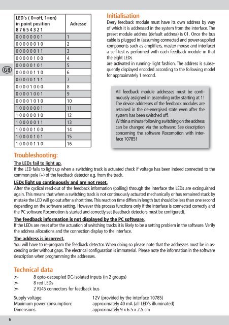
LED‘s ( 0=off, 1=on)<br />
in point position Adresse<br />
8 7 6 5 4 3 2 1<br />
0 0 0 0 0 0 0 1 1<br />
0 0 0 0 0 0 1 0 2<br />
0 0 0 0 0 0 1 1 3<br />
0 0 0 0 0 1 0 0 4<br />
0 0 0 0 0 1 0 1 5<br />
0 0 0 0 0 1 1 0 6<br />
0 0 0 0 0 1 1 1 7<br />
0 0 0 0 1 0 0 0 8<br />
0 0 0 0 1 0 0 1 9<br />
0 0 0 0 1 0 1 0 10<br />
1 0 0 0 0 0 0 1 11<br />
1 0 0 0 0 0 1 0 12<br />
1 0 0 0 0 0 1 1 13<br />
1 0 0 0 0 1 0 0 14<br />
1 0 0 0 0 1 0 1 15<br />
1 0 0 0 0 1 1 0 16<br />
Initialisation<br />
Every feedback <strong>module</strong> must have its own address by way<br />
of which it is addressed in the system from the interface. The<br />
preset <strong>module</strong> address (<strong>de</strong>fault address) is 01. Once the bus<br />
cable is plugged in (assuming connected and power-supplied<br />
components such as amplifiers, master mouse and interface)<br />
a self-test is performed with each feedback <strong>module</strong> in that<br />
the eight LEDs<br />
are activated in running- light fashion. The address is subsequently<br />
displayed enco<strong>de</strong>d according to the following mo<strong>de</strong>l<br />
for approximately 1 second.<br />
All feedback <strong>module</strong> addresses must be continuously<br />
assigned in ascending or<strong>de</strong>r starting at 1!<br />
The <strong>de</strong>vice addresses of the feedback <strong>module</strong>s are<br />
retained in the <strong>de</strong>-energised state even after the<br />
system has been switched off.<br />
Within a minute following switching on the address<br />
can be changed via the software: See <strong>de</strong>scription<br />
concerning the software <strong>Roco</strong>motion with interface<br />
10785!<br />
Troubleshooting:<br />
The LEDs fail to light up.<br />
If the LED fails to light up when a switching track is actuated check if voltage has been in<strong>de</strong>ed connected to the<br />
common pole (+) of the feedback <strong>de</strong>tector e.g. from the track.<br />
LEDs light up continuously and are not reset.<br />
After the cyclical read-out of the feedback information (polling) through the interface the LEDs are extinguished<br />
again. This means that when a switching track is not continuously actuated mechanically or has remained stuck by<br />
mistake the LED will go out after a short time. This reaction time differs in length but should be less than one second<br />
<strong>de</strong>pending on the software setting. However this process functions only if the interface is connected correctly and<br />
the PC software <strong>Roco</strong>motion is started and correctly set (feedback <strong>de</strong>tectors must be configured).<br />
The feedback information is not displayed by the PC software.<br />
If the LEDs are reset after the actuation of switching tracks it is likely to be a setting problem in the software. Verify<br />
the address allocations and the connection display to the interface.<br />
The address is incorrect.<br />
You will have to re-program the feedback <strong>de</strong>tector. When doing so please note that the addresses must be in ascending<br />
or<strong>de</strong>r without gaps. The electrical configuration is immaterial. Please note the information in the software<br />
<strong>de</strong>scription when programming the addresses.<br />
Technical data<br />
<br />
<br />
<br />
8 opto-<strong>de</strong>coupled DC-isolated inputs (in 2 groups)<br />
8 red LEDs<br />
2 RJ45 connectors for feedback bus<br />
Supply voltage: 12V (provi<strong>de</strong>d by the interface 10785)<br />
Maximum power consumption: approximately 40 mA (all LED‘s illuminated)<br />
Dimensions:<br />
approximately 9 x 6.5 x 2.5 cm<br />
6<br />
80<strong>10787</strong>920 XII_2005.indd 6 22.12.2005 10:00:11