Electronic Horn/Strobe Signal Appliances Installation Sheet
Electronic Horn/Strobe Signal Appliances Installation Sheet
Electronic Horn/Strobe Signal Appliances Installation Sheet
Create successful ePaper yourself
Turn your PDF publications into a flip-book with our unique Google optimized e-Paper software.
<strong>Electronic</strong> <strong>Horn</strong>/<strong>Strobe</strong> <strong>Signal</strong> <strong>Appliances</strong><br />
<strong>Installation</strong> <strong>Sheet</strong><br />
EN FR<br />
EN: <strong>Installation</strong> <strong>Sheet</strong><br />
Description<br />
The horn/strobes are high quality signals intended for use in<br />
general signaling applications. The strobes flash at 1 fps<br />
across their full operating voltage range.<br />
It is recommended that these products be installed in<br />
accordance with the requirements in the latest edition of<br />
national and local electrical codes.<br />
See Table 2 and Figure 1 for specifications.<br />
Table 1: <strong>Electronic</strong> horn/strobes<br />
Catalog number Description<br />
867STR(*)-** <strong>Horn</strong>/<strong>Strobe</strong>, Surface Mount Indoor, Gray<br />
868STR(*)-** <strong>Horn</strong>/<strong>Strobe</strong>, Surface Mount Outdoor, Gray<br />
869STR(*)-** <strong>Horn</strong>/<strong>Strobe</strong>, Flush or Panel Mount Indoor, Gray<br />
* Insert lens color: C = Clear, R = Red, G = Green, B = Blue or A =<br />
Amber.<br />
** The horns are available in two voltages. Insert suffix as required:<br />
N5 = 120V AC, AQ = 24V AC/DC<br />
<strong>Installation</strong><br />
WARNINGS<br />
• To reduce the risk of shock, do not connect AC or battery<br />
power to the horn until directed in these instructions.<br />
• To reduce the risk of shock, do not tamper with this device<br />
when the signal circuit is energized. Disconnect all power<br />
and wait 5 minutes for stored energy to dissipate before<br />
handling.<br />
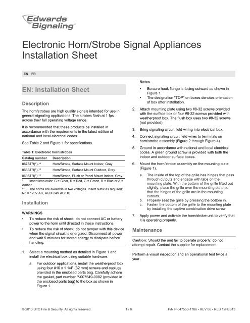
1. Select a mounting method as detailed in Figure 1 and<br />
install the electrical box using suitable hardware.<br />
a. For outdoor applications, install the weatherproof box<br />
using four #10 x 1 1/4" (32 mm) screws and caplugs<br />
provided in the enclosed parts bag. Carefully adhere<br />
the gasket, part number P-007549-0082 (provided in<br />
the enclosed parts bag) to the box as shown in<br />
Figure 1.<br />
Notes<br />
• Be sure hook flange is facing outward as shown in<br />
Figure 1.<br />
• The designation "TOP" on boxes denotes orientation<br />
of box after installation.<br />
2. Attach mounting plate using two #8-32 screws provided<br />
with the surface box or four #8-32 screws provided with<br />
weatherproof box. The flush box uses two #8-32 screws<br />
(not provided).<br />
3. Bring signaling circuit field wiring into electrical box.<br />
4. Connect signaling circuit field wires to terminals on<br />
horn/strobe assembly (Figure 2 through Figure 4).<br />
5. Ground in accordance with national and local electrical<br />
codes. A green ground screw is provided with both the<br />
indoor and outdoor surface boxes.<br />
6. Mount the horn/strobe assembly on the mounting plate<br />
(Figure 1).<br />
a. The inside of the top of the grille has hinges that pass<br />
through cutouts and engage with tabs on the<br />
mounting plate. With the bottom of the grille lifted out<br />
slightly, place the grille over the mounting plate so<br />
that the hinges of the grille are in the mounting<br />
cutouts.<br />
b. Properly seat the grille by pressing the bottom in.<br />
c. Fasten the bottom of the grille to the mounting plate<br />
by installing the captive combination drive screw.<br />
7. Apply power and activate the horn/strobe unit to verify that<br />
it is operating properly.<br />
Maintenance<br />
Caution: Should the unit fail to operate properly, do not<br />
attempt repair. Contact the supplier for replacement.<br />
Perform a visual inspection and an operational test twice a<br />
year.<br />
© 2013 UTC Fire & Security. All rights reserved. 1 / 6 P/N P-047550-1786 • REV 06 • REB 12FEB13
Figure 1: Detailed view<br />
Figure 2: Wiring the horn and strobe on the same circuit<br />
2 / 6 P/N P-047550-1786 • REV 06 • REB 12FEB13
Figure 3: Wiring the horn and strobe on different circuits<br />
Figure 4: Wiring the horn and strobe on different circuits<br />
Table 2: Specifications<br />
Operating voltage*<br />
N5 model<br />
120 VAC<br />
50/60 Hz<br />
AQ model<br />
24 VAC<br />
50/60 Hz<br />
24 VDC<br />
Operating current, horn** 33 mA 72 mA 22 mA<br />
Operating current, strobe** 115 mA 390 mA 390 mA<br />
Flash rate (per second)<br />
Sound level output at 10 ft.<br />
(3.05 m) anechoic chamber<br />
Operating<br />
environment<br />
Indoor<br />
Outdoor<br />
Approximately 1 fps<br />
90 dBA nominal<br />
85% at 86°F (30°C) relative humidity;<br />
32 to 120°F (0 to 49°C) variable<br />
ambient temperature<br />
95% at 86°F (30°C) relative humidity;<br />
−31 to 150°F (−35°F to 66°C) variable<br />
ambient temperature<br />
*The operating voltage to the horn may be continuous or coded such<br />
as march time or a temporal pattern meeting ISO8201 (ANSI S3.41)<br />
Audible Emergency Evacuation <strong>Signal</strong>.<br />
**<strong>Horn</strong> and strobe currents are additive when connected in parallel.<br />
Note: Cat. Nos. 867STR(*)-AQ, 868STR(*)-AQ and<br />
869STR(*)-AQ potentially generate timing signals or pulses<br />
above 9 kHz and therefore have been tested and found to<br />
comply with the limits for a Class A digital device, pursuant to<br />
Part 15 of the FCC Rules. These limits are designed to provide<br />
reasonable protection against harmful interference when the<br />
equipment is operated in a commercial environment. This<br />
equipment generates, uses and can radiate radio frequency<br />
energy and, if not installed and used in accordance with the<br />
instruction manual, may cause harmful interference to radio<br />
communications. Operation of this equipment in a residential<br />
area is likely to cause harmful interference in which case the<br />
user will be required to correct the interference at his own<br />
expense.<br />
Caution: Changes or modifications to this equipment not<br />
expressly approved by the party responsible for compliance<br />
could void the user's authority to operate the equipment.<br />
Contact information<br />
For contact information, see www.edwardssignaling.com<br />
FR: Fiche d’installation<br />
Description<br />
Les klaxons/stroboscopes sont des appareils de signalisation<br />
de haute qualité conçus pour les applications générales de<br />
signalisation. Les stroboscopes clignotent à 1 éclat par<br />
seconde, quelle que soit la tension appliquée à l’intérieur de<br />
leur gamme de tension de fonctionnement.<br />
Il est recommandé de toujours installer ces appareils<br />
conformément à la dernière édition en vigueur des codes<br />
nationaux et locaux d’électricité.<br />
Voir le tableau 2 et les figure 1 pour les caractéristiques<br />
techniques.<br />
P/N P-047550-1786 • REV 06 • REB 12FEB13 3 / 6
Tableau 1: Klaxon/stroboscopes<br />
Cat.<br />
Description<br />
67STR(*)-** Klaxon/stroboscope, gris, montage en saillie à<br />
l'intérieur<br />
868STR(*)-**<br />
869STR(*)-**<br />
Klaxon/stroboscope, gris, montage en saillie à<br />
l'extérieur<br />
Klaxon/stroboscope, gris, montage a l'intérieur<br />
encastre ou sur panneau<br />
* Insérer le code de couleur du diff useur, C = incolore, R = rouge,<br />
G = vert, B = bleu, A = ambre.<br />
** Insérer le suffi xe pertinent : N5 = 120 V c.a., AQ = 24V c.a./c.c.<br />
<strong>Installation</strong><br />
MISE EN GARDE<br />
• Pour réduire le risque de choc électrique, débranchez<br />
toutes les sources d'alimentation avant de toucher à<br />
l'appareil.<br />
• Pour réduire le risque de choc électrique, ne touches pas<br />
à l'appareil lorsque le circuit est sous tension. Avant<br />
d'intervenir sur l'appareil, débranchez toutes les sourcves<br />
d'alimentation et attendez cinq minutes pour permettre à<br />
l'énergie emmagasinée de se dissiper.<br />
sur la plaque de montage de façon à ce que ses<br />
charnières s’engagent dans les fentes de la plaque de<br />
montage.<br />
b. Appuyez sur le bas de le grille pour la mettre en<br />
place.<br />
c. Fixez le bas de la grille sur la plaque au moyen de la<br />
vis imperdable.<br />
7. Mettez l’appareil sous tension et déclenchez-le pour<br />
vérifier qu’il fonctionne correctement.<br />
Entretien<br />
MISE EN GARDE : Si l'appareil ne fonctionne pas<br />
correctement, n'essayez pas de le réparer. Addressez-vous au<br />
fournisseur pour obtenir un appareil de rechange.<br />
Examinez visuellement l’appareil et vérifi ez son<br />
fonctionnement deux fois par an.<br />
1. Choisissez la méthode de montage (voir la fi gure 1) et<br />
installez la boîte électrique au moyen des accessoires de<br />
fixation appropriés.<br />
Si l’appareil doit être installé à l’extérieur, installez la boîte<br />
étanche au moyen de quatre vis no10 x 1 1/4 po (32 mm)<br />
et des capuchons d’obturation fournis dans le sac de<br />
pièces. Collez soigneusement le joint d’étanchéité, pièce<br />
P-007549-0082 (fourni dans le sac de pièces) sur la boîte,<br />
comme illustré sur la fi gure 1.<br />
Remarque<br />
• Le rebord d’attache doit être vers l’extérieur,<br />
comme illustré sur la fi gure 1.<br />
• L’inscription “TOP” ou “DESSUS” sur les boîtes<br />
indique l’orientation de la boîte une fois installée.<br />
2. Fixez la plaque de montage au moyen des deux vis no 8-<br />
32 fournies avec la boîte de montage en saillie ou les<br />
quatre vis no 8-32 fournies avec la boîte étanche. La boîte<br />
encastrée utilise deux vis no 8-32 (non fournies).<br />
3. Tirez à l’intérieur de la boîte électrique les fi ls externes du<br />
circuit de signalisation.<br />
4. Raccordez les fi ls du circuit de signalisation aux bornes<br />
du klaxon/stroboscope (fi gures 2 à 4).<br />
5. Raccordez l’appareil à la terre conformément aux codes<br />
électriques national et local. Ue vis verte est prévue à cet<br />
eff et sur les boîtes en saillie pour l’intérieur et pour<br />
l’extérieur.<br />
6. Fixez le klaxon sur la plaque de montage (Fig. 1) :<br />
a. Le haut de la grille comporte, à l’intérieur, des<br />
charnières qui passent dans les fentes et s’engagent<br />
avec les pattes de fi xation sur la plaque de montage.<br />
Soulevez légèrement le bas de la grille et placez-la<br />
4 / 6 P/N P-047550-1786 • REV 06 • REB 12FEB13
Figure 1: Vue détaillée<br />
Figure 2: Raccordement du klaxon et du stroboscope sur le même circuit<br />
P/N P-047550-1786 • REV 06 • REB 12FEB13 5 / 6
Figure 3: Raccordement du klaxon et du stroboscope sur des circuits différents<br />
Figure 4: Bornier<br />
Tableau 2: Caractéristiques techniques<br />
Modèle N5 Modèle AQ<br />
Tension de fonctionnement* 120V c.a. 24V c.a. 24V c.c.<br />
Courant de fonctionnement -<br />
Klaxon**<br />
Courant de fonctionnement -<br />
Stroboscope**<br />
Fréquence des éclats<br />
Puissance sonore a 10 pieds<br />
(3,05 m) Chambre anéchoïde<br />
Conditions<br />
ambiantes<br />
33 mA 72 mA 22 mA<br />
115 mA 390 mA 390 mA<br />
Approximately 1 fps<br />
90 dBA nominal<br />
À l'intérieur 85% d'humidité relative à 86 °F (30<br />
°C); temp. ambiante de<br />
32 à 120 °F (0 à 49 °C)<br />
À l'extérieur 95% d'humidité relative à 86 °F (30<br />
°C); temp. ambiante de<br />
-31 à 150 °F (-35 à 66 °C)<br />
Remarque : Les modèles 867STR(*)-AQ, 868STRC-AQ et<br />
869STR(*)-AQ peuvent générer des signaux ou des impulsions<br />
de plus de 9 kHz et ont de ce fait subi des essais prouvant leur<br />
conformité aux limites prescrites pour les dispositifs<br />
numériques de classe A, selon la Partie 15 des Règles de la<br />
FCC. Ces limites visent à off rir une protection raisonnable<br />
contre le brouillage préjudiciable lorsque l'équipement est<br />
utilisé dans un secteur commercial. Cet appareil génère, utilise<br />
et peut émettre des fréquences radioélectriques et peut, s'il<br />
n'est pas installé et utilisé conformément à cette notice<br />
d'installation, engendrer du brouillage préjudiciable sur les<br />
communications radio. L'utilisation de cet appareil dans une<br />
zone résidentielle pourrait générer du brouillage préjudiciale<br />
auquel cas il incombe à l'utilisateur de prendre, à ses frais, le<br />
mesures qui s'imposent pour remédier à la situation.<br />
Mise en garde : Toute modification apportée à cet appareil<br />
sans l'approbation expresse de l'autorité compétente en<br />
matière de conformité pourrait résulter dans l'interdiction<br />
d'utiliser l'appareil.<br />
Coordonnées<br />
Pour les coordonnées, voir www.edwardssignaling.com.<br />
* La tension de fonctionnement appliquée au klaxon peut être<br />
continue ou codée, p. ex. suivant la cadence de marche ou suivant<br />
la cadence temporelle conforme à l'ISO 8201 (ANSI S3.41), <strong>Signal</strong><br />
sonore d'évacuation d'urgence.<br />
** Si le klaxon et le stroboscope sont branchés en parallèle, leurs<br />
courants s'ajoutent.<br />
6 / 6 P/N P-047550-1786 • REV 06 • REB 12FEB13


