
You also want an ePaper? Increase the reach of your titles
YUMPU automatically turns print PDFs into web optimized ePapers that Google loves.
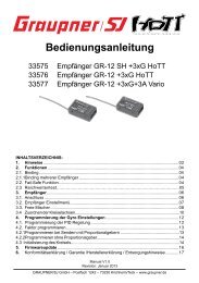
Bedienungsanleitung BRUSHLESS CONTROL 8 - 70 Best.-Nr. 7231 - 7237<br />
Herzlichen Glückwunsch zum Kauf des vielseitigen brushless Reglers für Bürstenlose Motoren von <strong>Graupner</strong>. Bürstenlose<br />
Antriebe bieten eine hohe Leistung und hohen Wirkungsgrad bei geringem Gewicht und kleinen Abmessungen. Eine<br />
erfolgreiche Anwendung setzt aber die Einhaltung bestimmter Grundsätze voraus.<br />
Lesen Sie bitte vor der Inbetriebnahme diese Bedienungsanleitung aufmerksam durch.<br />
Warnhinweise:<br />
- Das CE-Zertifikat des Reglers entbindet nicht der Verpflichtung, äußerste Vorsicht zu wahren.<br />
- Sollte der Motor einmal nicht wie gewünscht anlaufen oder bei einem Absturz stellen Sie den Senderknüppel sofort auf<br />
Motorposition aus, um eine Überlastung des Reglers zu vermeiden. Überprüfen Sie noch mal den richtigen Anschluss des<br />
Motors, kürzen Sie eventuell die Kabel und stellen Sie bei Bedarf am Sender eine Zeitverzögerung für die Gasannahme ein, um<br />
Timingfehler zu verhindern.<br />
- Benutzen Sie nur Motoren von GM-Racing oder <strong>Graupner</strong>, die für den verwendeten Spannungsbereich vorgesehen sind!<br />
- Verwenden Sie nur Hochleistungsakkus von GM-Racing oder <strong>Graupner</strong>. Akkus mit einem zu hohen Innenwiderstand können<br />
zur Zerstörung des Reglers führen! Benutzen Sie auf keinen Fall ein Netzteil für die Stromversorgung!<br />
- Lassen Sie Ihr RC-Modell niemals unbeaufsichtigt, solange ein Akku angesteckt ist. Im Falle eines Defektes, könnte dies<br />
Feuer am Modell oder seiner Umgebung verursachen.<br />
- Der Fahrtenregler oder andere elektronische Komponenten dürfen niemals mit Wasser in Berührung kommen. Der<br />
Fahrtenregler ist vor Staub, Schmutz, Feuchtigkeit, Vibration und anderen Fremdteilen zu schützen.<br />
- Sie dürfen niemals den Motor mit einem separaten Akku laufen lassen. Dies zerstört den Regler und Motor und führt zum<br />
Verlust der Garantie.<br />
- Verpolen Sie Ihren Regler nicht. Benutzen Sie verpolsichere Stecksysteme. Vermeiden Sie Kurzschlüsse und blockierende<br />
Motoren.<br />
- Alle Kabel und Verbindungen sollen gut isoliert sein. Kurzschlüsse können zur Zerstörung Ihres Reglers führen.<br />
- Nicht für Kinder unter 14Jahren, kein Spielzeug!<br />
- Die Regler sind ausschließlich für den Einsatz in Batterie- bzw. Akkubetriebenen, funkferngesteuerten Modellen vorgesehen,<br />
ein anderweitiger Betrieb ist nicht zulässig. Der Gebrauch in einem Modell zur Personenbeförderung ist verboten!<br />
- Motoren, Getriebe, Schiffs- oder Luftschrauben sind gefährliche Gegenstände. Halten Sie sich daher niemals neben oder vor<br />
dem Gefährdungsbereich des Antriebes auf!<br />
- Technische Defekte mechanischer oder elektronischer Teile können zum unverhofften Anlaufen des Motors und<br />
herumfliegenden Teilen führen, die erhebliche Verletzungen verursachen können.<br />
- Führen Sie immer zuerst einen Reichweitetest und Funktionstest am Boden durch (halten Sie dabei Ihr Modell fest), bevor Ihr<br />
Modell zum Einsatz kommt. Wiederholen Sie den Test bei laufendem Motor und mit kurzen Gasstößen.<br />
- Es dürfen keinerlei Veränderungen am Regler durchgeführt werden, es sei denn, diese sind in der Anleitung beschrieben.<br />
- Haftungsausschluss: Sowohl die Einhaltung der Montage- und Bedienungsanleitung, als auch die Bedingungen und Methoden<br />
bei Installation, Betrieb, Verwendung und Wartung des Fahrtenreglers können von der Fa. <strong>Graupner</strong> nicht überwacht werden.<br />
Daher übernimmt die Fa. <strong>Graupner</strong> keinerlei Haftung für Verluste, Schäden oder Kosten, die sich aus fehlerhafter Verwendung<br />
und Betrieb ergeben, oder in irgendeiner Weise damit zusammenhängen.<br />
- Es dürfen nur von uns empfohlene Komponenten und Zubehörteile verwendet werden. Verwenden Sie nur zueinander<br />
passende, Original GRAUPNER - Steckverbindungen und Zubehörteile.<br />
- Vergewissern Sie sich vor jeder Inbetriebnahme bevor Sie den Fahrtenregler einstecken, dass: Ihr Sender als einziger auf der<br />
Frequenz Ihres Empfängers sendet und Ihr Sender eingeschaltet ist und der Gashebel auf der Position STOP steht.<br />
UMerkmale des Elektronischen Fahrtreglers (ESC) für bürstenlose Motoren<br />
1. Voll proportionale Vorwärtsfahrt mit Bremse EIN/AUS und Rückwärtsgang.<br />
2. Sanfter Gaseinsatz<br />
3. Sowohl auf Außen- wie auf Innenläufer perfekt abgestimmt, ohne zusätzliches Einstellen.<br />
4. Motor-Drehrichtung kann gewählt werden.<br />
5. Mit Li-Po, NiCd und NiMH-Akkus verwendbar.<br />
6. Modellart wählbar (Flächen-, Hubschrauber-, Boots- oder Automodell).<br />
7. Programmierbare Bremse Automatische / Minimale / Maximale Bremskraft).<br />
8. Drehzahlregler (governor) AN / AUS (nur Heli).<br />
9. Vorwärtsgang oder Vor- und Rückwärtsgang (Boote und Autos).<br />
10. Automatische Abschaltung bei Niedrigspannung, abgestimmt auf die Eingangsspannung.<br />
11. 32 kHz Schaltfrequenz.<br />
12. Thermische Abschaltung bei Übertemperatur.<br />
13. Automatische Speicherung der Senderhebelstellung.<br />
14. Absteckbare Set-Taste<br />
Anschlüsse des Drehzahlstellers:<br />
Die Akkukabel haben ein BEC- Stecksystem (#7231, #7232) bzw. ein G2 (#7233, #7236) oder ein G 3,5 Stecksystem (#7234,<br />
#7237). Verwenden Sie daher nur <strong>Graupner</strong> Akkus mit dem gleichen Stecksystem. Die Kabel zum Antriebsakku dürfen<br />
insgesamt max. 20cm lang sein.<br />
Der Drehzahlsteller wird mit dem Motor mit Buchsen vom Typ G3,5 verlötet. Dabei werden an den drei Kabeln des<br />
Drehzahlstellers G3,5 Buchsen Best.-Nr. 2969 verwendet. Am Motor sollen die Stecker G3,5 Best.-Nr. 2970 angebracht<br />
sein/werden. Die Motorkabel können auch direkt verlötet werden.
Einbau ins Modell und Inbetriebnahme, Einstellen der Gasknüppelpositionen am ESC:<br />
UESC Pieptöne : Do, Re, Mi, Fa, So, La, Ti, Do.<br />
- Der Motor wird mit Schrauben am Motorspant befestigt. Verwenden Sie nur in der Länge passende Schrauben oder<br />
verwenden Sie Unterlegscheiben. Beim Anziehen von zu langen Schrauben werden Sie den Motor mit Sicherheit zerstören.<br />
- Den Drehzahlsteller montieren Sie so im Modell, dass die Kühlfläche frei bleibt. Sorgen Sie für ausreichende Kühlung des<br />
Motors und des Drehzahlstellers durch reichlich dimensionierte Kühlluftöffnungen.<br />
1. Richtige Verkabelung des Motors prüfen.<br />
2. Schalten Sie den Sender ein und überprüfen Sie den Weg des Motordrossel-Kanals, der +/- 100% und bei Multiplex<br />
Fernsteueranlagen +/- 80% sein sollte. Bei Robbe/Futaba muss der „Gasweg“ umgedreht werden (REVERSE)! Bei<br />
<strong>Graupner</strong>/JR muss dieser auf „NORMAL“ eingestellt sein. Der Gashebel muss auf der Position „Bremse“ bzw.<br />
„Motor aus“ stehen! Die Gaswege des Reglers sind fest programmiert und können gegebenenfalls am Sender<br />
verändert werden.<br />
3. Sender einschalten („EIN“), dann den Gashebel in Stellung „Motor aus/Bremse“ bringen.<br />
4. Batterie/Akku mit richtiger Polarität an den Regler anschließen.<br />
Wenn alle Verbindungskabel richtig angeschlossen sind, muss der Motor je nach Knüppelstellung folgende Pieptöne von sich<br />
geben:<br />
Do, Re ~~ Do, Re, Mi : Wenn der Gashebel in Stellung STOP steht.<br />
Do, Re ~~ : Wenn der Gashebel NICHT in Stellung STOP steht.<br />
5. Wenn Sie den Set-Taster an der Tasterbox länger als 1 Sekunde gedrückt halten, muss die grüne LED blinken.<br />
Nehmen Sie jetzt den Finger vom Set-Taster. Der Motor wird etwa so piepsen: So, So, La, La, So, So und die grüne LED muss<br />
einmal blinken.<br />
6. Drücken Sie den Gashebel in die Vollgas-Position, drücken Sie den Taster herunter und lassen Sie ihn gleich wieder los. Die<br />
grüne LED muss nun zweimal blinken und damit anzeigen, dass die Vollgas- Position gesetzt ist.<br />
7. Bringen Sie den Gashebel nun in die Neutral-Position (falls Sie 3 Fixpositionen gewählt haben) oder auf Minimum-Position<br />
(falls Sie 2 Fixpositionen gewählt haben), drücken Sie den SET-Taster und lassen Sie ihn gleich wieder los. Die grüne LED<br />
muss nun dreimal blinken und damit anzeigen, dass die Neutral- Position (bei Wahl von 3 Fixpositionen) oder die Minimum-<br />
Position (bei 2 Fixpositionen) gesetzt ist.<br />
8. Wenn Sie hier 2 Fixpositionen wählen wollen, bleiben Sie in der Neutral-Position und lassen Sie den Schalter los.<br />
Wenn Sie 3 Fixpositionen wählen wollen, führen Sie den Gashebel in die Minimal-Position (Vollbremse) zurück, drücken Sie<br />
den SET-Taster kurz und lassen Sie ihn dann los. Wenn das Einstellen der Gashebelpositionen beendet ist, muss der Motor<br />
folgendermaßen piepsen: So, Fa, Mi, Re, Do, und die zwei LEDs müssen im Wechsel blinken.<br />
Wenn Sie während des Einstellvorgangs den falschen Steuerknüppel bewegen, blinkt die grüne LED einmal und der ESC<br />
erwartet einen Reset. Erst wenn die dritte Stellung eingestellt ist, kann die Bremse aktiviert werden, und zwar mit Auto Brake<br />
Amount (Auto-Bremskraft), Minimum Brake Amount (Minimale Bremskraft), Maximum Brake Amount (Maximale Bremskraft).<br />
Achtung: Dieses erstmalige Einstellen des Gasgriffs ist nur notwendig, wenn Sie einen anderen Sender benützen oder wenn die<br />
Einstellungen geändert sind.<br />
Einstellungen des Programmiermodus<br />
1. Sender einschalten.<br />
2. Batterie anschließen, dann muss der ESC sich automatisch einschalten.<br />
3. Wenn alle Verbindungskabel richtig angeschlossen sind, muss der Motor je nach Knüppelstellung folgende Pieptöne von sich<br />
geben:<br />
Do, Re ~~ Do, Re, Mi : Wenn der Gasgriff in Stellung STOP steht.<br />
Do, Re ~~ : Wenn der Gasgriff NICHT in Stellung STOP steht..<br />
4. Wenn Sie den Set-Taster an der Schalterbox länger als 1 Sekunde gedrückt halten, muss die grüne LED blinken und wenn<br />
Sie den SET-Taster weitere 4 Sekunden lang gedrückt halten, muss die rote LED blinken. Wenn Sie jetzt den SET-Taster<br />
loslassen, piept der ESC Mi, Re, Do, Re, Mi, und die rote LED zeigt andauerndes Einfachblinken. Damit wird angezeigt, dass<br />
der ESC jetzt im Programmiermodus ist.<br />
Nehmen Sie jetzt die Hand vom Setup-Schalter. Der Motor wird etwa so piepen: So, So, La, La, So, So und die grüne LED<br />
muss einmal blinken.<br />
Bei andauerndem Einfachblinken geht der ESC zur Einstellung des Batterie-Typs über. Vier verschiedene Programmpunkte<br />
können an diesem Controller eingestellt werden (siehe folgende Liste).<br />
UBatterie-Typ für alle Anwendungen<br />
UDrehrichtung des Motors in allen Anwendungen<br />
Drehzahlregler AN/AUS bei Heli-Modellen / Vorwärts oder vorwärts/rückwärts bei Auto- und Bootsmodellen<br />
Auswahl Flug-, Heli-, Boots- oder Automodell
Set-Taster: jedes Mal, wenn dieser Taster gedrückt wird, wechselt die Programmfunktion.<br />
Die rote LED blinkt entsprechend dem folgenden Muster:<br />
1) Rote LED blinkt einmal ( bereit zum Einstellen des Batterie-Typs )<br />
2) Rote LED blinkt zweimal ( bereit zum Einstellen der Motor-Drehrichtung )<br />
3) Rote LED blinkt dreimal ( bereit zum Einstellen: Drehzahlregler EIN/AUS, Vor/Rückfahrt )<br />
4) Rote LED blinkt viermal ( bereit zum Einstellen: Flug-, Heli-, Auto- oder Bootsmodell)<br />
Wenn Sie in einer Programmfunktion, die Sie ändern möchten, den Set-Taster 2 Sekunden lang drücken, blinken beide LEDs.<br />
Jedes Mal, wenn der Set-Taster gedrückt wird, ändert sich die Programmfunktion wie folgt:<br />
1) Batterie-Typ :<br />
LEDs blinken einmal für LiPo, zweimal für NiCd/MH.<br />
2) Wahl der Motor-Drehrichtung:<br />
LEDs blinken einmal für Vorwärtsfahrt, zweimal für die umgekehrte Richtung.<br />
3) Heli-Modell : LEDs blinken einmal für Governor (Drehzahlregelung) AUS, zweimal für Governor AN.<br />
Boots- und Automodell : LEDs blinken einmal für nur vorwärts, zweimal für Vor/Rückwärtsfahrt.<br />
4) Modell-Wahl :<br />
LEDs blinken einmal für Flugmodell, zweimal für Helimodell<br />
LEDs blinken dreimal für Bootsmodell, viermal für Automodell<br />
Sobald Sie Ihre gewünschten Einstellungen vorgenommen haben, drücken Sie den Set-Taster über zwei Sekunden lang, um<br />
die Einstellungen im ESC zu speichern. Der Motor piept dann Mi, Re, Do, und die rote LED blinkt. Sie können jetzt keine<br />
anderen Programmfunktionen mehr wählen.<br />
Wenn Sie jetzt noch einen anderen Programm-Parameter ändern wollen, müssen Sie die obige Prozedur wiederholen. Wenn<br />
aber alle Parameter gesetzt sind, können Sie den Fahrtenregler abschalten.<br />
Die grundlegenden Operationen am ESC nach dem Einschalten sind:<br />
Sicherheitsstellung des Knüppels (bei Minimal-Gas) Töne: Do, Re .<br />
Hinweis: wenn Sie nur Do und Re – oder Do, Re, Do, Re, Mi – hören, können Sie die Knüppelstellungen festlegen oder in den<br />
Programmiermodus wechseln.<br />
• LED-Status während der Bedienung:<br />
Vollgas : Rote LED an<br />
Neutral : Grüne LED an<br />
Voll zurück oder Vollbremsung : Beide LEDs an<br />
Fehler : Rote LED blinkt<br />
• Weitere Erklärungen zur Fehler-Meldung:<br />
Kein Signal: Rote LED blinkt 5 Sekunden lang und geht dann aus: Warten auf das Signal.<br />
Hohe Temperatur, niedriger Batterie-Ladezustand : Grüne LED ist in der Neutralstellung an, und beim Bewegen des<br />
Gashebels blinkt die rote LED.<br />
Viele angenehme Stunden wünscht Ihnen <strong>Graupner</strong> GmbH & Co. KG!<br />
EG-Konformitätserklärung:<br />
Für die folgende bezeichneten Erzeugnisse<br />
PROGRAMMIERGERÄT für BRUSHLESS CONTROL Regler Best.-Nr. 7230<br />
BRUSHLES CONTROL 8 Best.-Nr. 7231<br />
- BRUSHLES CONTROL 70 Best.-Nr. 7237<br />
wird hiermit bestätigt, dass es den wesentlichen Schutzanforderungen entspricht, die in der Richtlinie des Rates zur<br />
Angleichung der Rechtsvorschriften der Mitgliedstaaten über die elektromagnetische Verträglichkeit (2004/108/CE) festgelegt<br />
sind.<br />
Zur Beurteilung des Erzeugnisses wurden folgende Normen herangezogen:<br />
EN 61000-6-1<br />
EN 61000-6-3<br />
Diese Erklärung wird verantwortlich für den Hersteller/Importeur<br />
<strong>Graupner</strong> GmbH & Co. KG<br />
Henriettenstr. 94-96<br />
73230 Kirchheim/Teck<br />
abgegeben durch den Geschäftsführer Hans <strong>Graupner</strong><br />
73230 Kirchheim/Teck, den 05.08.08 Unterschrift
Technische Daten:<br />
Best.-Nr. 7231 7232 7233 7234 7236 7237<br />
Betriebsspannungsbereich: 5,5…15V 5,5…15V 5,5…15V 5,5…25V 5,5…25V 5,5…25V<br />
Zellenzahl Ni-MH/Ni-Cd: 6 – 12 6 – 12 6 – 12 6 – 18 6 – 18 6 – 18<br />
LiPo/LiIo 2 – 4 2 – 4 2 – 4 2 – 6 2 – 6 2 – 6<br />
Dauerstrom: 8A 18A 35A 45A 60A 70A<br />
Max. Motorstrom 10s: 12A 22A 40A 50A 70A 80A<br />
Übertemperaturschutz ca. 120°C/125°C<br />
EMK-Bremse: programmierbar<br />
Sanftanlauf: ja<br />
Einschaltruckunterdrückung: ja<br />
Taktfrequenz ca. 32 kHz<br />
BEC getaktet: 5,5 V/2 A 5,5 V/2 A 5,5 V/2 A 5,5V/3A 5,5V/3A 5,5V/3A<br />
OPTO: -<br />
Abmessungen in mm ca. 30x22,5x8 39x22,5x8 49x26x10 70x26x11 70x26x11 70x26x11<br />
Gewicht mit Kabel ca. 18 g 23 g 41 g 52 g 56 g 60 g<br />
Akkustecker: BEC BEC G2 G3,5 G2 G3,5<br />
Hinweise zum Umweltschutz<br />
Das Symbol auf dem Produkt, der Gebrauchsanleitung oder der Verpackung weist darauf hin, dass dieses<br />
Produkt am Ende seiner Lebensdauer nicht über den normalen Haushaltsabfall entsorgt werden darf. Es muss an<br />
einem Sammelpunkt für das Recycling von elektrischen und elektronischen Geräten abgegeben werden.<br />
Die Werkstoffe sind gemäß ihrer Kennzeichnung wieder verwertbar. Mit der Wiederverwendung, der stofflichen<br />
Verwertung oder anderen Formen der Verwertung von Altgeräten leisten Sie einen wichtigen Beitrag zum<br />
Umweltschutz.<br />
Batterien und Akkus müssen aus dem Gerät entfernt werden und bei einer entsprechenden Sammelstelle getrennt entsorgt<br />
werden.<br />
Bitte erkundigen Sie sich bei der Gemeindeverwaltung die zuständige Entsorgungsstelle.
Instruction Manual BRUSHLESS CONTROL 8 - 70 Order-No. 7231 - 7237<br />
Congratulations for buying this state of the art brushless speed controller. It is adapted for use with high efficient and powerful<br />
brushless motors.<br />
Important notice:<br />
Please read this manual carefully before using your controller. Only then can you have full profit of the potential of<br />
your controller, and avoid mistakes.<br />
Warnings:<br />
- The controller's CE certificate doesn't unbind users from their obligation to use ultimate caution<br />
- Should the motor refuse to start up, or after a crash, then you should immediately set the transmitter's control stick to the OFF<br />
position to avoid any overload to the controller.<br />
- Use only motors delivered by GM-Racing or <strong>Graupner</strong> which are designed for the intended range of voltages!<br />
- Use only high performance batteries by <strong>Graupner</strong> or GM-Racing. Using batteries with an increased internal resistance may<br />
lead to the destruction of the controller! Do never use a power supply.<br />
- Never leave your transmitter unattended when a battery is connected. In case of a deficiency this may cause an outbreak of<br />
fire on the model or its environment.<br />
- Neither the controller nor any other electronic components should ever come in touch with water. Protect the controller against<br />
dust, dirt, humidity, vibrations, or other dangerous elements (with the exception of water-sealed controllers).<br />
- Never run the motor on a separate battery. This will destroy the controller or the motor, and leads to the loss of our warranty.<br />
- Never mix up polarities. Use plug systems which offer protection against wrong polarity. Avoid short-circuiting and blocking the<br />
motors.<br />
- All cables and connectors should have good insulation. Short-circuits may lead to the destruction of your motor.<br />
- This product isn't designed for use by children under the age of 14, it isn't a toy!<br />
- <strong>Graupner</strong>-controllers are designed for use in battery-driven, radio-controlled models only; any other use is not permissible.<br />
Using this device on a passenger-carrying model is forbidden!<br />
- Motors, gears or gearboxes, and propellers are dangerous objects. Never keep next to or in front of the danger area of the<br />
drive!<br />
- Technical defects or failures of mechanical or electronic parts may lead to an unexpected start-up of the motor, with parts of it<br />
flying off, maybe causing severe injuries.<br />
- Always check the service range of transmission of your model first thing while it's still on the ground (hold the model tightly!).<br />
Try again with motor on and also with fast changes of the throttle stick.<br />
- Don't make any changes on the structure and design of your controller unless they are described in the manual!<br />
- Limited warranty: <strong>Graupner</strong> Ltd cannot survey the proper application of the mounting and using regulations, nor the working<br />
methods and conditions during the installation, use, operation, and servicing of the controller. Therefore <strong>Graupner</strong> Ltd cannot<br />
take on any liability for any loss, damage, or costs resulting from an incorrect use or operation of the product, or connected in<br />
any way with incorrect use or operation.<br />
- Only those components and accessory parts which have been recommended by us may be used. Use only genuine and<br />
matching <strong>Graupner</strong> connectors and accessory parts.<br />
- Make sure whenever you start connecting and operating the controller, that:<br />
- your transmitter is the only one working on that frequency,<br />
- is switched on,<br />
- and has the throttle set to position “STOP”.<br />
- Use only high-quality batteries by <strong>Graupner</strong> or GM-Racing. Cheap or old batteries with a high internal resistance may lead to<br />
poor performance or even to the destruction of the controller.<br />
Connecting the speed controller:<br />
Use only batteries with the same connection type as the speed controller is delivered with.<br />
The speed controller should be connected to the motor with gold connectors G3.5. Use G3.5 female Order-No. 2969 for the<br />
speed controller motor wires. Use G3.5 gold plugs female Order-No. 2970 for the motor wires.<br />
ESC features.<br />
1. Fully proportional forward with on/off brake and reverse<br />
2. Smooth throttle response<br />
3. Perfect compatible with both inrunner and outrunner motors without setting.<br />
4. Motor rotation direction can be set.<br />
5. Li-Po, NiCd and NiMH battery compatible<br />
6. Selectable model type (Air, Heli, Boat, Car)<br />
7. Various Brake( Auto / Minimum / Maximum Brake amout)<br />
8. Governor On / Off (Only Heli)<br />
9. One Way / Two Way (Boat & Car)<br />
10. Automatically sets low-voltage cutoff based on input voltage<br />
11. 32 kHz switching frequency<br />
12. Thermal cutoff<br />
13. Auto store on the stick Position.<br />
14. pluggable SET-button<br />
Installing into the model:<br />
- Attach the motor to the motor mount using the screws provided. Adjust the effective screw length (place washers<br />
under the head) so that the threads do not protrude protruding inside the motor casing. The winding of your motor can<br />
be damaged, if the screws protrude inside the motor case. See motor instructions.<br />
- Mount the speed controller in the model so that it is isolated from vibration and shock and make sure the heatsink is<br />
free for best cooling. Make sure that there is sufficient cooling of the motor and speed controller by directing adequate<br />
cooling air from the outside airflow.
Setting the Standard Mode / First operation<br />
ESC Stick Position setup<br />
1. Make sure all the cable leads are properly connected.<br />
ESC sound : Do, Re, Mi, Fa, So, La, Ti Do.<br />
2. Turn the transmitter on and check the servo travel of the throttle channel which should be ±100% or, with Multiplex R/C<br />
systems, ±80%. Robbe/Futaba systems need reversing (REVERSE) the throttle arm travel! With <strong>Graupner</strong>/JR systems, the<br />
latter should be set to “NORMAL”. The throttle trigger should now be either at position “Brake” or at “Motor off”! The throttle<br />
range is fixed. You may correct the transmitter way on the transmitter.<br />
3. Turn the transmitter on (position “ON”), then push the throttle lever into position “Motor off / Brake”.<br />
4. Connect the battery to the controller, mind the correct polarity. Plug in the power battery and try only once to plug in. Do not<br />
touch the contact several times.<br />
5. If all wire connections are correctly connected, the motor should beep depending on the throttle stick position as like :<br />
Do, Re ~~ Do, Re, Mi : When the throttle stick in the stop position.<br />
Do, Re ~~ : When the throttle stick is NOT in the stop position.<br />
6. If you press and hold the Setup switch on the Switch box for over 1 second, the Green LED should flash.<br />
At this time, if your hand is released from the Setup switch. The motor should beep like So, So, La, La, So, So and the Green<br />
LED should flash one time.<br />
7. Move the throttle sticker to the full position and press and release the switch, the Green LED should flash twice to indicate<br />
that the full position has been set.<br />
8. Move again the throttle stick to the neutral position ( if 3 position was set ) or minimum position ( if 2 position was set ) and<br />
press and release the switch, the Green LED should flash triple time to indicate that the neutral position for 3 position or<br />
minimum position for 2 position has been set,<br />
9. At this stage, if you want to set 2 position, stay at the neutral position and press and release the switch /<br />
If you want to set 3 position, move back the throttle stick to the minimum position and press and release the switch. After<br />
finish the stick position setting above, the motor should beep like So, Fa, Mi, Re, Do sounds and the both LED should flash<br />
alternately.<br />
During the setting procedure, if you set wrong throttle stick, the Green LED should flash one time and the ESC is waiting for<br />
resetting. Only after 3 position is set, the brake should be activated with Auto Brake Amount, Minimum Brake Amount,<br />
Maximum Brake Amount<br />
Note : It is ONLY necessary to make this initial throttle setup again if you are using a different transmitter or the settings have<br />
been changed.<br />
Programmable mode setting<br />
1. Turn on the transmitter.<br />
2. Connect the power battery, then the ESC should be automatically ON.<br />
3. If all wire connections are correctly connected, the motor should beep depending on the throttle stick position as like :<br />
Do, Re ~~ Do, Re, Mi : When the throttle stick in the stop position.<br />
Do, Re ~~ : When the throttle stick is NOT in the stop position.<br />
4. If you press and hold the switch for over 1 second the Green LED should flash and if you continue to press and hold the<br />
switch for over 4 seconds, the Red LED should flash. At this stage, if you release the switch, the ESC should beep Mi, Re, Do,<br />
Re, Mi sound and the Red LED should flash once constantly to indicate that the ESC is now in the programmable mode setting.<br />
Flashing repeatedly once enters the Battery type setting. 4 different program features can be set in this controllers as below.<br />
Battery Type for all application<br />
Motor rotation direction for all application<br />
Governor Off or On for Heli / One or Two Way for Boat & Car<br />
Select Air / Heli / Boat / Car<br />
Setup Switch: The program function will change every time the Setup Switch is pressed.<br />
. The Red LED will flash in accordance with the features as follows<br />
1) Red LED flashes once ( Battery type setting available )<br />
2) Red LED flashes twice ( Motor rotation direction setting available )<br />
3) Red LED flashes three times (Governor Off/On, One/Two Way setting available )<br />
4) Red LED flashes four times ( Model type Air or Heli or Boat or Car setting available )<br />
If you press the Setup switch for over 2 seconds at a program function that you would like to change, the both LEDs should<br />
flash.
Every time the Setup switch is pressed, the program function is as like :<br />
1) Battery type :<br />
LEDs flashes once for Li-Po , LEDs flashes twice for NiCd/MH.<br />
2) Motor rotation direction selecting:<br />
LEDs flashes once for Forward direction, LEDs flashes twice for Reverse direction.<br />
3) Heli Model : LEDs flashes once for Governor Off, LEDs flashes twice for Governor On.<br />
Boat & Car Model : LEDs flashes once for One Way, LEDs flashes twice for Two Way.<br />
4) Select Model :<br />
LEDs flashes once for Air, LEDs flashes twice for Heli<br />
LEDs flashes three times for Boat, LEDs flashes four times for Car<br />
After you finish your wanted setting, press the Setup switch for over 2 seconds then the ESC should store the setting values, the<br />
motor should beep Mi, Re,Do sound the the Red LED should flash which means you can not select other program function.<br />
At this stage, if you want to change another program parameter, repeat the procedure above, or if all settings are complicated,<br />
turn off the speed controller.<br />
The basic operation on the ESC when the power is on.<br />
Stick safety location ( throttle minimum ) Do,Re sound.<br />
Note) after ONLY hearing Do and Re~~~~ or Do,Re~~~Do,Re,Mi sound, you can set Stick position or Programmable mode<br />
setting.<br />
• LED status during operation.<br />
Full Throttle : Red LED on<br />
Neutral : Green LED on<br />
Full Reverse or Full Brake : Both LED on<br />
Error : Red LED flashes<br />
• additional comments on the Error<br />
No Signal : Red LED should flash for 5 seconds then OFF. Waiting for the signal.<br />
High Temperature, Low Battery : Green LED should be ON at the neutral position, and if the stick moves, the Red LED should<br />
flash.<br />
<strong>Graupner</strong> GmbH & Co. KG wishes you many safe flights and happy landings.<br />
EG declaration of conformity<br />
for the products<br />
PROGRAMMER for BRUSHLESS CONTROL Order-No. 7230<br />
BRUSHLES CONTROL 8 Order.-No. 7231<br />
- BRUSHLES CONTROL 70 Order.-No. 7237<br />
We confirm that the electromagnetic compatibility directives (2004/108/CE) are met.<br />
Harmonized standards applied:<br />
EN 61000-6-1<br />
EN 61000-6-3<br />
<strong>Graupner</strong> GmbH & Co. KG<br />
Henriettenstr. 94-96<br />
73230 Kirchheim/Teck<br />
Managing Director Hans <strong>Graupner</strong><br />
73230 Kirchheim/Teck, 05.08.08 Signature<br />
Environmental Protection Notes<br />
Individual markings indicate which materials can be recycled and re-used. You can make an important<br />
contribution to the protection of our common environment by re-using the product, recycling the basic materials or<br />
recycling redundant<br />
equipment in other ways.<br />
Specifications:<br />
When this product comes to the end of its useful life, you must not dispose of it in the ordinary domestic waste.<br />
The correct method of disposal is to take it to your local collection point for recycling electrical and electronic<br />
equipment. The symbol shown here, which may be found on the product itself, in the operating instructions or on<br />
the packaging, indicates that this is the case.<br />
Remove batteries from your device and dispose of them at your local collection point for batteries.<br />
If you don’t know the location of your nearest disposal centre, please enquire at your local council office.
Order-No. 7231 7232 7233 7234 7236 7237<br />
Operating voltag e:<br />
5,5…15V 5,5…15V 5,5…15V 5,5…25V 5,5…25V 5,5…25V<br />
cells Ni-MH/Ni-Cd: 6 – 12 6 – 12 6 – 12 6 – 18 6 – 18 6 – 18<br />
cells LiPo/LiIo 2 – 4 2 – 4 2 – 4 2 – 6 2 – 6 2 – 6<br />
continous curren t:<br />
8A 18A 35A 45A 60A 70A<br />
max. current 10s: 12A 22A 40A 50A 70A 80A<br />
temperature protection ~ 120°C/125°C<br />
brake: programmable<br />
soft start: yes<br />
Frequency app rox. 32 kHz<br />
Switching BEC: 5,5 V/2 A 5,5 V/2 A 5,5 V/2 A 5,5V/3A 5,5V/3A 5,5V/3A<br />
OPTO: -<br />
size in mm approx. 30x22,5x8 39x22,5x8<br />
49x26x10 70x26x11 70x26x11 70x26x11<br />
weight incl. wires approx. 18 g 23 g 41 g 52 g 56 g 60 g<br />
battery plug: BEC BEC G2 G3,5 G2 G3,5
Instructions d’utilisation pour les régulateurs BRUSHLESS CONTROL 8 – 70 Réf. N°7231 - 7237<br />
Félicitations pour votre acquisition d’un régulateur <strong>Graupner</strong> pour les moteurs Brushless Les propulsions avec un moteur<br />
Brushless offrent une très grande puissance et un haut rendement pour un faible poids et de petites dimensions.<br />
Veuillez lire attentivement ces instructions d’utilisation avant la mise en service.<br />
Avertissements :<br />
- Le certificat CE du régulateur ne dispense pas de prendre des précautions d’utilisation.<br />
- Si le moteur ne démarre pas comme souhaité ou après un crash, ramenez immédiatement le manche des gaz sur la<br />
position moteur coupé pour éviter une surcharge au régulateur. Vérifiez à nouveau le raccordement correct du<br />
moteur, raccourcissez éventuellement les fils d’alimentation et réglez au besoin un temps de retardement de la mise<br />
des gaz dans l’émetteur pour éviter une erreur de calage.<br />
- Utilisez uniquement des moteurs de la marque GM-Racing ou <strong>Graupner</strong> pour lesquels la plage des tensions utilisées<br />
est prévue !<br />
- Utilisez uniquement les accus de haute puissance GM-Racing ou <strong>Graupner</strong>. Les accus avec une résistance trop<br />
élevée peuvent conduire à la destruction du régulateur ! N’utilisez en aucun cas un transformateur de courant secteur<br />
pour l’alimentation !<br />
- Ne laissez jamais votre modèle R/C sans surveillance tant qu’un accu de propulsion est connecté. Dans le cas d’une<br />
défectuosité, le modèle peut prendre feu et le communiquer à son environnement.<br />
- Les régulateurs ou les autres éléments électroniques ne doivent jamais venir en contact avec l’eau. La régulateur<br />
devra être protégé de la poussière, des salissures, de l’humidité, des vibrations et d’autres corps étrangers.<br />
- Ne faites jamais tourner le moteur avec un accu séparé. Ceci détruira le régulateur et le moteur et conduira à la perte<br />
du bénéfice de la garantie.<br />
- N’inversez jamais les polarités du régulateur ; utilisez un système de connecteurs avec sécurité contre les inversions<br />
de polarité .Evites les court-circuites et les blocages du moteur.<br />
- Tous les fils et les raccordements devront être bien isolés ; un court-circuit pourra détruire le régulateur<br />
- Cet appareil ne convient pas aux enfants en dessous de 14 ans, ce n’est pas un jouet !<br />
- Le régulateur est exclusivement prévu pour l’équipement des modèles radiocommandés avec une alimentation par<br />
des accus. toute autre utilisation n’est pas admissible !<br />
- Les moteurs, les réducteurs, les hélices marines ou aériennes sont des objets dangereux. Pour cette raison, ne vous<br />
tenez jamais à côté ou devant la zone dangereuse des propulsions !<br />
- Une défectuosité mécanique ou électrique inopinée au démarrage du moteur peut provoquer la projection de pièces<br />
et causer de sérieuses blessures.<br />
- Effectuez toujours d’abord un essai de porté et des fonctions au sol avant de faire voler votre modèle (en le<br />
maintenant fermement !). Répétez ces essais avec le moteur en marche, avec de courts passages à plein gaz.<br />
- Aucunes modifications ne devront être apportées sur le régulateur, mises à part celles décrites dans ces instructions.<br />
- Exclusion de responsabilité : Le respect des instructions de montage et d’utilisation, aussi bien que les conditions et<br />
les méthodes d’installation, d’utilisation et d’entretien ne peuvent pas être surveillées par la Firme <strong>Graupner</strong>. Pour<br />
cette raison, la Firme <strong>Graupner</strong> décline toute responsabilité pour les pertes, les dégâts ou les coûts survenus à la<br />
suite d’une mauvaise utilisation, ou sa participation d’une façon quelconque aux dédommagements.<br />
- Il conviendra d’utiliser uniquement les composants et les accessoires que nous conseillons. Utilisez uniquement des<br />
connecteurs et des accessoires d’origine GRAUPNER adaptés entre-eux.<br />
- Avant de connecter votre régulateur, assurez-vous que votre émetteur est le seul à émettre sur la fréquence que vous<br />
utilisez et avant de le mettre en contact, que le manche des gaz est sur la position STOP.<br />
Particularités des régulateurs de vitesse électroniques (ESC) pour les moteurs sans balais<br />
1. Marche avant totalement proportionnelle avec frein Commuté/Décommuté et passage en marche arrière<br />
2. Démarrage souple<br />
3. Adaptation parfaite aussi bien pour les Outrunner que pour les Inrunner, sans réglages supplémentaires<br />
4. Le sens de rotation du moteur peut être sélectionné<br />
5. Utilisable avec les accus LiPo, NiCd et NiMH<br />
6. Genres de modèles sélectionnables (à voilure, hélicoptères, bateaux ou voitures)<br />
7. Force du freinage automatique programmable (Minimale/Maximale)<br />
8. Régulateur de régime CONTACT/COUPE (seulement pour hélicoptère)<br />
9. Passage en marche avant et/ou passage en marche arrière (Bateaux et voitures)<br />
10. Coupure automatique sous faible tension, accordée sur la tension de la réception<br />
11. Cadence de fréquence 32 kHz<br />
12. Coupure thermique en surtempérature<br />
13. Mémorisation automatique de la position du manche de l’émetteur<br />
14. Touche Set fixable<br />
Raccordement du régulateur :<br />
Le cordon de raccordement à l’accu porte un système de connecteur BEC (#7231, #7232), ou un système de connecteurs<br />
G2(#7233, #7236) ou bien G3,5 (#7234, #7237). Pour cette raison, utilisez uniquement des accus <strong>Graupner</strong> avec le même<br />
système de connecteur. Le cordon vers l’accu de propulsion doit avoir une longueur totale max. de 20 cm.<br />
Le régulateur sera relié au moteur avec de fiches femelles du type G3,5 soudées ; pour cela, utiliser des fiches G3,5, Réf.<br />
N°2969 sur les trois fils du régulateur et des fiches mâles G3,5, Réf. N°2970 sur les fils du moteur. Les fils du moteur pourront<br />
aussi être soudés directement.
Montage dans le moteur et mise en service, réglage des position du manche des gaz sur le régulateur (ESC) :<br />
Tons des Bips ESC : Do, Ré, Mi, Fa, Sol, La, Si, Do.<br />
- Fixez le moteur sur le couple avant avec des vis ; utiliser uniquement des vis d’une longueur adaptée, ou interposez des<br />
rondellesd plates. En utilisant des vis trop longues, le moteur sera sûrement détérioré.<br />
- Montez le régulateur dans le modèle de façon à ce que la surface de refroidissement reste libre Assurez un refroidissement<br />
efficace au moteur et au régulateur par des entrées d’air suffisamment dimensionnées.<br />
1. Vérifiez le câblage correct du moteur.<br />
2. Mettez l’émetteur en contact et vérifiez le réglage de la course de la voie des gaz ; il doit être de +/- 100% et de +/-<br />
80% avec les ensembles R/C Multiplex. Avec les ensembles Robbe/Futaba, la course des gaz devra être inversée<br />
(REVERSE). Avec les ensembles <strong>Graupner</strong>/JR, elle devra être réglée sur ‘’NORMAL’’. Le manche des gaz devra être<br />
placé sur la position ‘’Frein’’ ou ‘’Moteur coupé’’ ! La course des gaz du régulateur est fixement programmée et pourra<br />
le cas échéant être modifiée dans l’émetteur.<br />
3. Mettez l’émetteur en contact (‘’EIN’’) et placez le manche des gaz sur la position ‘’Moteur coupé/Frein’’.<br />
4. Reliez le régulateur à l’accu de propulsion dans la bonne polarité.<br />
Lorsque routes les liaisons sont correctement établies, le moteur devra émettre les Bips suivants selon la position du manche<br />
des gaz :<br />
Do, Ré ~~ Do, Ré, Mi Lorsque le manche des gaz est sur la position STOP<br />
Do, Ré ~~ Lorsque le manche des gaz n’est PAS sur la position STOP<br />
5. Lorsque la touche Set est maintenue pressée durant plus de 1 seconde, le LED vert doit clignoter. Retirez maintenant votre<br />
doigt de la touche Set. Le moteur émettra les Bips Sol, Sol, La, La, Sol, Sol et le LED vert devra clignoter une seule fois.<br />
6. Poussez le manche des gaz sur la position pleins gaz, pressez la touche vers le bas puis relâchez là. Le LED vert doit<br />
maintenant clignoter trois fois et indiquer ainsi que la position pleins gaz est fixée.<br />
7. Placez le manche des gaz sur la position Neutre (si vous avez sélectionné 3 positions fixes) ou sur la position Minimum (si<br />
vous avez sélectionné 2 positions fixes), pressez la touche Set et relâchez là. Le LED vert doit maintenant clignoter trois fois et<br />
indiquer ainsi que la position Neutre (avec la sélection de 3 positions) ou la position Minimum (avec 2 positions) est fixée.<br />
8. Lorsque vous voulez sélectionner ici 2 positions fixes, restez dans la position Neutre et relâchez la touche. Si vous voulez<br />
sélectionner 3 positions fixes ramenez le manche des gaz sur la position Minimale (Plein freinage), pressez brièvement la<br />
touche Set et relâchez là ensuite. Lorsque le réglage des positions du manche des gaz est terminé, le moteur doit émettre les<br />
Bips suivants Sol, Fa, Mi, Ré, Do et les deux LED doivent clignoter en alternance.<br />
Lorsque le manche des gaz est placé sur des fausses position durant le processus de réglage, le LED vert clignote une fois et<br />
le régulateur attend un Reset. Ce n’est que lorsque la troisième position est réglée que le frein pourra être activé et avec Auto<br />
Brake Amount (Force de freinage voiture), Minimum Brake Amount (Force de freinage Minimale) et Maximum Brake Amount<br />
(Force de freinage maximale).<br />
Attention : Ces réglages préliminaires du manche des gaz sont seulement nécessaires lorsque vous voulez utiliser un autre<br />
émetteur ou lorsque les réglages seront changés.<br />
Réglages du Mode programmation<br />
1. Mettez l’émetteur en contact.<br />
2. Reliez la batterie, le régulateur soit ensuite se commuter automatiquement.<br />
3. Lorsque toutes les liaisons sont correctement établies, le moteur devra émettre les Bips suivants selon la position du<br />
manche des gaz :<br />
Do, Ré ~~ Do, Ré, Mi Lorsque le manche des gaz est sur la position STOP<br />
Do, Ré ~~ Lorsque le manche des gaz n’est PAS sur la position STOP<br />
4. Lorsque la touche Set est maintenue pressée durant plus de 1 seconde, le LED vert doit clignoter et lorsqu’elle est<br />
pressée durant 4 autres secondes, le LED rouge doit clignoter. Lorsque vous relâchez maintenant la touche Set, le<br />
régulateur émet les Bips Mi, Ré, Do, Ré, Mi et le clignotement permanent du LED rouge indique que le régulateur est<br />
maintenant dans le Mode programmation.<br />
Relâchez maintenant la touche Set. Le moteur émettra les Bips Sol, Sol, La, La, Sol, Sol et le LED vert devra clignoter<br />
une seule fois.<br />
Avec le clignotement unique en permanence, le régulateur passe dans le réglage du type de batterie. Quatre points de<br />
programmation pourront être réglés sur ce régulateur (Voir la liste suivante).<br />
Type de batterie pour toutes les applications<br />
Sens de rotation du moteur dans toutes les applications<br />
Régulateur de régime CONTACT/COUPE pour les modèles d’hélicoptères/Marche avant ou Marche avant/Marche<br />
arrière pour les modèles de voitures et de bateaux<br />
Sélection pour modèles à voilure, hélicoptères, modèles de bateaux ou de voitures
Touche Set : La fonction de programmation s’échange chaque fois que cette touche est pressée.<br />
Le LED rouge clignote en correspondance des réglages suivants :<br />
1) Le LED rouge clignote une fois (Prêt pour le réglage du type de batterie)<br />
2) Le LED rouge clignote deux fois (Prêt pour le réglage su sens de rotation du moteur)<br />
3) Le LED rouge clignote trois fois (Prêt pour les réglages : Régulateur de régime CONTACT/COUPE, Marche avant/Marche<br />
arrière.<br />
4) Le LED rouge clignote quatre fois (Prêt pour les réglages : modèles à voilure, d’hélicoptères, de voitures ou de bateaux.<br />
Lorsque vous voulez passer d’une fonction de programme dans une autre, pressez la touche Set durant 2 secondes ; les deux<br />
LED clignotent.<br />
Chaque fois que la touche Set sera pressée, la fonction de programmation changera comme suit :<br />
1) Type de batterie :<br />
Les LED clignotent une fois pour LiPo, deux fois pour NiCd/MH.<br />
2) Sélection du sens de rotation du moteur :<br />
Les LED clignotent une fois pour Marche avant, deux fois pour le sens inverse.<br />
3) Modèles d’hélicoptères : Le LED clignote une fois pour régulateur de régime COUPE, deux fois pour CONTACT<br />
Modèles de bateaux et de voitures : Le LED clignote une seule fois pour Marche avant, deux fois pour Marche arrière.<br />
4) Sélection de modèle :<br />
Les LED clignotent une fois pour les modèles volants, deux fois pour les modèles d’hélicoptères.<br />
Les LED clignotent trois fois pour les modèles de bateaux, quatre fois pour les modèles de voitures.<br />
Dès que vous aurez effectué vos réglages désirés, pressez la touche Set durant 2 secondes pour les mémoriser dans le<br />
régulateur. Le moteur émettra ensuite les Bips Mi, Ré, Do et le LED rouge clignotera. Vous ne pouvez plus maintenant<br />
sélectionner aucune autre fonction de programmation.<br />
Lorsque vous désirerez modifier encore maintenant un autre paramètre de programmation, vous devrez répéter la procédure cidessus.<br />
Lorsque tous les paramètres seront fixés, vous pourrez couper le régulateur.<br />
Les opérations de base sur le régulateur après le mise en contact sont :<br />
Position de sécurité de manche des gaz (avec gaz minimal), Tons : Do, Ré.<br />
Note : Lorsque vous entendez seulement Do et Ré, ou seulement Do, Ré, Do, Ré, Mi, vous pourrez fixer les positions de<br />
manche ou changer dans le mode programmation.<br />
� Status des LED durant l’utilisation :<br />
Pleins gaz LED rouge allumé<br />
Neutre LED vert allumé<br />
Retour ou freinage total Les deux LED sont allumés<br />
Erreur Le LED rouge clignote<br />
� Autres explications pour les avertissements d’erreur :<br />
Aucun signal : Le LED rouge clignote durant 5 secondes et passe ensuite sur : Attente du signal.<br />
Haute température, faible état der charge de la batterie : Le LED vert est allumé dans la position Neutre et le LED rouge<br />
clignote avec un déplacement du manche des gaz.<br />
<strong>Graupner</strong> GmbH & Co. KG vous souhaite de nombreuses heures agréables !<br />
Caractéristiques techniques :<br />
Réf. N° 7231 7232 7233 7234 7236 7237<br />
Plage de tensions d’alimentation 5,5…15V 5,5…15V 5,5…15V 5,5…25V 5,5…25V 5,5…25V<br />
Nombre d’éléments NiMH/NiCd: 6 – 12 6 – 12 6 – 12 6 – 18 6 – 18 6 – 18<br />
LiPo/LiIo 2 – 4 2 – 4 2 – 4 2 – 6 2 – 6 2 – 6<br />
Courant permanent: 8A 18A 35A 45A 60A 70A<br />
Courant moteur max. 10s: 12A 22A 40A 50A 70A 80A<br />
Protection en sur température, env. 120°C/125°C<br />
Fein électromagnétique programmable<br />
Démarre souple oui<br />
Impulsions soutenues oui<br />
Cadence de fréquence, env. 32 kHz<br />
Alimentation réception BEC 5,5 V/2 A 5,5 V/2 A 5,5 V/2 A 5,5V/3A 5,5V/3A 5,5V/3A<br />
OPTO: -<br />
Dimensions rn mm env. 30x22,5x8 39x22,5x8 49x26x10 70x26x11 70x26x11 70x26x11<br />
Poids avec câblage, env. 18 g 23 g 41 g 52 g 56 g 60 g<br />
Connecteur accu BEC BEC G2 G3,5 G2 G3,5
Déclaration de conformité EG :<br />
Pour les produits suivants :<br />
PROGRAMMIERGERÄT für BRUSHLESS CONTROL Regler Best.-Nr. 7230<br />
BRUSHLES CONTROL 8 Réf. N° 7231<br />
- BRUSHLES CONTROL 70 Réf. N° 7237<br />
Nous confirmons que la compatibilité électronique correspond aux directives (2004/108/CE).<br />
Normes appliquées :<br />
EN 61000-6-1<br />
EN 61000-6-3<br />
<strong>Graupner</strong> GmbH & Co. KG<br />
Henriettenstr. 94-96<br />
73230 Kirchheim/Teck<br />
Le Directeur d’Entreprise, Hans <strong>Graupner</strong> Signature<br />
73230 Kirchheim/Teck, 05.08.08<br />
Indications quand à la protection de l'environnement<br />
Ce produit à la fin de sa durée de vie ne doit pas être mis à la poubelle, mais être remis à une collecte pour le<br />
recycle ment d'appareils électriques et électroniques. Le symbole inscrit sur le produit, dans la notice<br />
d'instructions et sur son emballage l'indique.<br />
Les matériaux selon leurs reconnaissances sont réutilisables. Avec le recyclage de matériaux et autres formes<br />
d'appareils, vous contribuez à la protection de l'environnement.<br />
Les batteries et accus doivent être retirés de l'appareil et doivent être remis à un dépôt homologué pour ce type de produits.<br />
Veuillez s.v.p. demander auprès de votre mairie l'adresse exacte de la collecte la plus proche de chez vous.