GDW Ref. 1508 Alfa 156 Crosswagon Q4 2004 - Winparts.nl
GDW Ref. 1508 Alfa 156 Crosswagon Q4 2004 - Winparts.nl
GDW Ref. 1508 Alfa 156 Crosswagon Q4 2004 - Winparts.nl

Create successful ePaper yourself
Turn your PDF publications into a flip-book with our unique Google optimized e-Paper software.
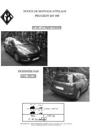
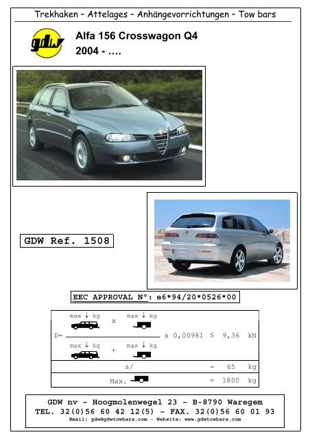
Trekhaken – Attelages – Anhängevorrichtungen – Tow bars<br />
<strong>Alfa</strong> <strong>156</strong> <strong>Crosswagon</strong> <strong>Q4</strong><br />
<strong>2004</strong> - ….<br />
<strong>GDW</strong> <strong>Ref</strong>. <strong>1508</strong><br />
EEC APPROVAL N°: e6*94/20*0526*00<br />
max kg<br />
D=<br />
max kg<br />
+<br />
x max kg x 0,00981 ≤ 9,36 kN<br />
max kg<br />
s/ = 65 kg<br />
Max. = 1800 kg<br />
<strong>GDW</strong> nv – Hoogmolenwegel 23 – B-8790 Waregem<br />
TEL. 32(0)56 60 42 12(5) – FAX. 32(0)56 60 01 93<br />
Email: gdw@gdwtowbars.com - Website: www.gdwtowbars.com
<strong>Alfa</strong> <strong>156</strong> <strong>Crosswagon</strong> <strong>Q4</strong><br />
<strong>2004</strong> - ….<br />
<strong>Ref</strong>. <strong>1508</strong><br />
T35 Escamotable
Montagehandleiding<br />
<strong>Alfa</strong> <strong>156</strong> <strong>Crosswagon</strong> <strong>Q4</strong><br />
<strong>2004</strong> - ….<br />
<strong>Ref</strong>. <strong>1508</strong><br />
1) Uitlaat en hitteschild achteraan demonteren, reservewiel en bekleding in de kofferruimte wegnemen.<br />
2) Monteer de kogelstang of de behuizing van het afneembaar systeem reeds op de trekhaak. Positioneer de<br />
trekhaak met de punten (A) op de reeds voorziene openingen aan de onderzijde van de rechter<br />
chassisbalk. boor de gaten door tot in de kofferruimte en vergroot deze tot ø25mm. Breng de<br />
bijgeleverde buisjes (5) en (6) in de chassisbalk via de vergrote boringen en plaats de contraplaat (2) met<br />
de punten (A) en (A’) op deze buisjes, breng de bouten in en schroef deze handvast. Boor de punten (C)<br />
door met ø8,5mm en breng de bouten in, plaats onderaan het voertuig de contraplaten (1). Schroef de<br />
bouten handvast.<br />
3) Aan de linkerzijde onderaan de chassisbalk zijn er 2 voorziene boringen, boor deze loodrecht door tot in<br />
de kofferruimte. Vergroot deze boringen enkel in de kofferruimte tot ø25mm en breng de buisjes (5) in<br />
de chassisbalk. Plaats de monteerplaat (3) met de punten (B) op de ingebrachte buisjes en breng de<br />
bouten in, plaats onderaan de contraplaat(4) op de bouten en schroef deze handvast.<br />
4) Plaats de trekhaak in de juiste positie en boor de punten (D) door tot in de bak van het reservewiel met<br />
ø10,5mm. De punten (D) van de monteerplaat (3) komen te passen met de gemaakte boringen. Breng de<br />
bouten in en schroef alles degelijk vast.<br />
5) Monteer het hitteschild en de uitlaat terug op voertuig. Breng de bekleding en het reservewiel terug in de<br />
koffer.<br />
Samenstelling<br />
Trekhaak referentie <strong>1508</strong><br />
1 bolstang T43L000 (*) 4 bouten M8x35 - DIN931 (8.8) (C)<br />
2 bouten M12x40 (8.8) (*) 4 moeren M8 - DIN934 (C)<br />
2 bouten M12x40 - DIN7991 (10.9) (*’) 1 monteerstuk (ref.3) (B-D)<br />
2 moeren M12 - DIN934 (*’) 1 monteerstuk (ref.2) (A-A’)<br />
3 bouten M10x110 - DIN931 (8.8) (A-B) 2 monteerlatjes (ref.1) (C)<br />
1 bout M10x120 - DIN931 (8.8) (A’) 1 monteerlatje (ref.4) (B)<br />
7 moeren M10 - DIN934 (A-A’-B-D) 7 borgrondsels M10 - DIN128A (A-A’-B-D)<br />
3 bouten M10x30 - DIN933 (8.8) (D) 4 borgronsels M8 - DIN128A (C)<br />
1 buisje ø25x5,5x80mm (ref.6) (A’) 3 buisjes ø25x5,5x74mm (ref.5) (A-B)<br />
4 borgronsels M12 - DIN128A (*-*’)<br />
N.B.<br />
Voor de maximum toegestane massa welke uw voertuig mag trekken dient U uw dealer te raadplegen.<br />
Verwijder eventueel de bitume<strong>nl</strong>aag op de bevestigingsplaats van de trekhaak.<br />
Opgepast bij het boren dat men geen remleiding, elektriciteitsdraden of brandstofleidingen beschadigt.
Notice de montage<br />
<strong>Alfa</strong> <strong>156</strong> <strong>Crosswagon</strong> <strong>Q4</strong><br />
<strong>2004</strong> - ….<br />
Réf. <strong>1508</strong><br />
1) Démonter le pot d’échappement et la plaque thermique derrière, supprimer la roue de secours et le<br />
revêtement des parois du coffre.<br />
2) Monter la rotule ou le pied du système escamotable sur l’attelage. Positionner l’attelage avec les points<br />
(A) sur les ouvertures déjà prévus au côté inférieur de la poutre du châssis droite. Perforer les trous<br />
jusque dans le coffre et agrandir ces trous jusque ø25mm. Insérer les tubes (5) et (6) par les trous<br />
agrandits dans la poutre du châssis et placer la plaque (2) avec les points (A) et (A’) sur ces tubes, insérer<br />
les boulons sans serrer. Perforer les points (C) avec ø8,5mm et insérer les boulons, placer les plaques (1)<br />
au bas du véhicule. Ne pas serrer les boulons.<br />
3) Au côté gauche, au bas de la poutre du châssis, il y a 2 trous prévus, perforer ceux-là verticalement jusque<br />
dans le coffre. Agrandir ces trous uniquement dans le coffre jusque ø25mm et insérer les tubes (5) dans<br />
la poutre du châssis. Placer la plaque de montage (3) avec les points (B) sur les tubes introduits insérer<br />
les boulons, placer la plaque (4) au côté inférieur sur les boulons sans serrer.<br />
4) Placer l’attelage dans la bonne position et perforer les points (D) jusque dans le logement de roue avec<br />
ø10,5mm. Les points (D) de la plaque de montage (3) s’adaptent au trous faits. Insérer les boulons et<br />
bien visser le tout.<br />
5) Remonter la plaque thermique et l’échappement. Replacer le revêtement des parois et la roue de rechange<br />
dans le coffre.<br />
Composition<br />
Attelage référence <strong>1508</strong><br />
1 rotule T43L000 (*) 4 boulons M8x35 - DIN931 (8.8) (C)<br />
2 boulons M12x40 (8.8) (*) 4 écrous M8 - DIN934 (C)<br />
2 boulons M12x40 - DIN7991 (10.9) (*’) 1 pièce de montage (3) (B-D)<br />
2 écrous M12 - DIN934 (*’) 1 pièce de montage (-f) (A-A’)<br />
3 boulons M10x110 - DIN931 (8.8) (A-B) 2 lattes de montage (1) (C)<br />
1 boulon M10x120 - DIN931 (8.8) (A’) 1 latte de montage (4) (B)<br />
7 écrous M10 - DIN934 (A-A’-B-D) 7 rondelles de sûreté M10 - DIN128A (A-A’-B-D)<br />
3 boulons M10x30 - DIN933 (8.8) (D) 4 rondelles de sûreté M8 - DIN128A (C)<br />
1 tube ø25x5,5x80mm (6) (A’) 3 tubes ø25x5,5x74mm (5) (A-B)<br />
4 rondelles de sûreté M12 - DIN128A (*-*’)<br />
Remarque<br />
Pour le poids de traction maximum autorisé de votre voiture, consulter votre concessionaire.<br />
E<strong>nl</strong>ever la couche de bitume ou d’anti-tremblement qui recouvre éventuellement les points de fixation.
Fitting instructions<br />
<strong>Alfa</strong> <strong>156</strong> <strong>Crosswagon</strong> <strong>Q4</strong><br />
<strong>2004</strong> - ….<br />
<strong>Ref</strong>. <strong>1508</strong><br />
1) Disassemble the exhaust and the heat shield in the back, remove the spare wheel and the inner coating in<br />
the trunk.<br />
2) Assemble the ball or the pedestal of the escamotable system already on the tow bar. Place the tow bar<br />
with points (A) on the already provided openings on the underside of the right chassis beam. Drill the<br />
holes through till in the trunk en e<strong>nl</strong>arge these holes till ø25mm. Insert the tubes (5) and (6) in the chassis<br />
beam through the e<strong>nl</strong>arged drillings and place the plate (2) with points (A) and (A’) on these tubes, insert<br />
the bolts but do not tighten yet. Drill the points (C) through with ø8,5mm and insert the bolts, place the<br />
plates (1) at the bottom of the vehicle. Do not tighten the bolts.<br />
3) There are 2 drillings provided on the left side at the bottom of the chassis beam which have to be drilled<br />
perpendicularly through till in the trunk. E<strong>nl</strong>arge these drillings o<strong>nl</strong>y in the trunk till ø25mm and insert<br />
the tubes (5) in the chassis beam. Place mounting plate (3) with points (B) on the inserted tubes and<br />
insert the bolts, place the plate (4) at the bottom but do not tighten yet.<br />
4) Place the tow bar in the right position and drill points (D) through till in the spare wheel tray with<br />
ø10,5mm. Points (D) of mounting plate (3) match the made drillings. Insert the bolts and tighten<br />
everything firmly.<br />
5) Re-assemble the heat shield and the exhaust on the vehicle. Replace the inner coating and the spare<br />
wheel in the trunk.<br />
Composition<br />
Tow bar reference <strong>1508</strong><br />
1 ball T43L000 (*) 4 bolts M8x35 - DIN931 (8.8) (C)<br />
2 bolts M12x40 (8.8) (*) 4 nuts M8 - DIN934 (C)<br />
2 bolts M12x40 - DIN7991 (10.9) (*’) 1 mounting piece (3) (B-D)<br />
2 nuts M12 - DIN934 (*’) 1 mounting piece (-f) (A-A’)<br />
3 bolts M10x110 - DIN931 (8.8) (A-B) 2 mounting pieces (1) (C)<br />
1 bolt M10x120 - DIN931 (8.8) (A’) 1 mounting piece (4) (B)<br />
7 nuts M10 - DIN934 (A-A’-B-D) 7 security washers M10 - DIN128A (A-A’-B-D)<br />
3 bolts M10x30 - DIN933 (8.8) (D) 4 security washers M8 - DIN128A (C)<br />
1 tube ø25x5,5x80mm (6) (A’) 3 tubes ø25x5,5x74mm (5) (A-B)<br />
4 security washers M12 - DIN128A (*-*’)<br />
Note<br />
Please consult your cardealer or owners manual for the maximal permissable towing mass.<br />
Remove any bitumen coating on the fastening position for the tow bar.<br />
When drilling, be carefull not to damage any brake lines, electrical wiring or fuel lines.
Anbaua<strong>nl</strong>eitung<br />
<strong>Alfa</strong> <strong>156</strong> <strong>Crosswagon</strong> <strong>Q4</strong><br />
<strong>2004</strong> - ….<br />
<strong>Ref</strong>. <strong>1508</strong><br />
1) Auspuff und Wärmeschild abmontieren, Reserverad und Bekleidung in Kofferraum wegnehmen.<br />
2) Kugelstange oder Sockel von abnehmbar System schon auf Anhängerkupplung montieren. Anhängerkupplung<br />
mit Punkte (A) auf schon vorhandenen Öffnungen an Unterseite von rechte Chassisbalken<br />
setzen. Löcher bis in Kofferraum durchbohren und mit ø25mm vergrößern. Röhrchen (5) und (6) in<br />
Chassisbalken via vergrößte Bohrungen bringen und Platten (2) mit Punkte (A) und (A’) auf diese Röhre,<br />
Bolzen einbringen ohne anzuspannen. Punkte (C) mit ø8,5mm durchbohren und Bolzen einbringen,<br />
unten Fahrzeug Platten (1) setzen. Bolzen nicht anspannen.<br />
3) An linke Seite, unten Chassisbalken die 2 vorhandene Bohrungen lotrecht bis in Kofferraum durchbohren.<br />
Diese Bohrungen nur in Kofferraum bis ø25mm vergrößern und Röhre (5) in Chassisbalken bringen.<br />
Montierplatten (3) mit Punkte (B) auf die eingebrachte Röhre setzen und Bolzen einbringen, unten Platte<br />
(4) auf die Bolzen setzen ohne anzuspannen.<br />
4) Anhängerkupplung setzen und Punkte (D) bis in Reserveradraum durchbohren mit ø10,5mm. Punkte (D)<br />
von Montierplatte (3) stimmen mit die gemachte Bohrungen überein. Bolzen einbringen und Alles<br />
gediegen anspannen.<br />
5) Wärmeschild und Auspuff wieder auf Fahrzeug montieren. Bekleidung und Reserverad wieder in<br />
Kofferraum bringen.<br />
Zusammenstellung<br />
Anhängekupplung <strong>1508</strong><br />
1 Kugelstange T43L000 (*) 4 Bolzen M8x35 - DIN931 (8.8) (C)<br />
2 Bolzen M12x40 (8.8) (*) 4 Muttern M8 - DIN934 (C)<br />
2 Bolzen M12x40 - DIN7991 (10.9) (*’) 1 Montierstück (3) (B-D)<br />
2 Muttern M12 - DIN934 (*’) 1 Montierstück (-f) (A-A’)<br />
3 Bolzen M10x110 - DIN931 (8.8) (A-B) 2 Montierstücke (1) (C)<br />
1 Bolzen M10x120 - DIN931 (8.8) (A’) 1 Montierstück (4) (B)<br />
7 Muttern M10 - DIN934 (A-A’-B-D) 7 Sicherheitsritzel M10 - DIN128A (A-A’-B-D)<br />
3 Bolzen M10x30 - DIN933 (8.8) (D) 4 Sicherheitsritzel M8 - DIN128A (C)<br />
1 Röhrchen ø25x5,5x80mm (6) (A’) 3 Röhrchen ø25x5,5x74mm (5) (A-B)<br />
4 Sicherheitsritzel M12 - DIN128A (*-*’)<br />
Hinweise<br />
Die maximale Anhängelast Ihres Fahrzeuges können Sie im Fahrzeugschein oder im Benutzerhandbuch nachlesen.<br />
Im bereich er A<strong>nl</strong>ageflächen muβ Unterbodenschutz und Antidröhmaterial entfernt werden.<br />
Vor dem Bohren prüfen, daβ keine, dort eventuell Leitungen beschädigt werden können.
Trekhaken Attelages Anhängevorrichtungen Tow bars<br />
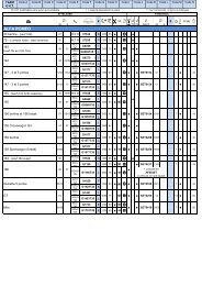
Bouten - Boulons - Bolts - Bolzen DIN 912 - DIN 931 - DIN 933 - DIN 7991<br />
Kwaliteit 8.8 (10.9)<br />
M6 10,8Nm of 1,1kgm M8 25,5Nm of 2,60kgm M10 52,0Nm of 5,30kgm<br />
M12 88,3Nm of 9,0kgm M14 137Nm of 14,0kgm M16 211,0Nm of 21,5kgm<br />
Bouten - Boulons - Bolts - Bolzen DIN 912 - DIN 931 - DIN 933 - DIN 7991<br />
Kwaliteit 10.9<br />
M6 13,7Nm of 1,4kgm M8 35,3Nm of 3,6kgm M10 70,6Nm of 7,20kgm<br />
M12 122,6Nm of 12,5kgm M14 194Nm of 19,8kgm M16 299,2Nm of 30,5kgm
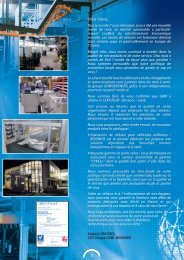
De tussenruimte conform supplement VII, afbeelding 30 van de<br />
richtlijn 94/20/EG moet in acht worden genomen.<br />
La zone de dégagement doit être garantie conformément à l’annexe<br />
VII, illustration 30 de la directive 94/20/CE.<br />
The clearance specified in appendix VII, diagram 30 of guideline<br />
94/20/EG must be guaranteed.<br />
Der Freiraum nach Anhang VII, Abbildung 30 der Richtlinie<br />
94/20/EG ist zu gewährl.<br />
Bij toelaatbaar totaal gewicht van het voertuig<br />
Pour poids total en charge autorisé du véhicle<br />
At laden weight of the vehicle<br />
Bei zulässigem Gesamtgewicht des Fahrzeuges