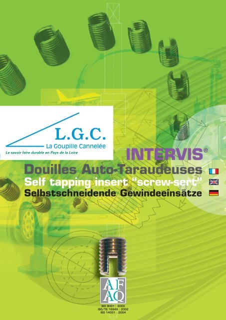
Intervis-Douilles Auto - LGC
Intervis-Douilles Auto - LGC
Intervis-Douilles Auto - LGC
- No tags were found...

You also want an ePaper? Increase the reach of your titles
YUMPU automatically turns print PDFs into web optimized ePapers that Google loves.
Le savoir faire durable en Pays de la Loire<br />
®<br />
Self tapping insert “screw-sert”<br />
Selbstschneidende Gewindeeinsätze<br />
ISO 9001 : 2000<br />
ISO/TS 16949 : 2002<br />
ISO 14001 : 2004
L’<strong>Intervis</strong> ®<br />
The Screw-sert<br />
L’<strong>Intervis</strong> ®<br />
La sécurité mécanique<br />
de vos assemblages<br />
A mechanical safety in<br />
your assembly<br />
Die mechanische<br />
Sicherung Ihrer Bauteile<br />
Technique <strong>Intervis</strong> ®<br />
Screw-sert technical<br />
Die <strong>Intervis</strong> ® Technik<br />
Dans les matériaux tendres et mi-durs (alliages<br />
légers, plastiques, bois comprimés,…) les<br />
taraudages résistent mal aux contraintes<br />
répétées. Si l’on serre trop énergiquement ou<br />
trop fréquemment la vis, les filets s’arrachent et<br />
la pièce est hors d’usage.<br />
Les solutions proposées, comme les douilles<br />
taraudées surmoulées (complication des<br />
moules et position souvent incorrecte), les<br />
filets rapportés (pré-taraudage obligatoire),<br />
sont coûteuses.<br />
La solution : l’INTERVIS ® L.G.C. « La Goupille<br />
Cannelée »<br />
Cet ensemble se comporte comme un taraud et<br />
permet de visser directement l’INTERVIS ® dans<br />
un trou lisse percé préalablement. L’INTERVIS ®<br />
taille lui-même le filetage dans la pièce.<br />
ÉBAUCHE et FINITION<br />
In soft and half-hard materials, (light alloys,<br />
plastics, compressed wood,...) tappings are<br />
badly holding to repeated constraints. If the<br />
screw is tightened excessively or too frequently,<br />
the threads will pull out and the part will<br />
brake up.<br />
The solutions proposed, as overmould tapped<br />
socket : in-mould threaded insert (complication<br />
of the moulds and position frequently incorrect),<br />
or pre-threading insert, are expensive.<br />
The solution : The <strong>LGC</strong> SCREW-SERT<br />
This set is performing as a tap and allows to<br />
screw down straight the SCREW-SERT in a<br />
smooth hole drilled first. The SCREW-SERT cuts<br />
himself the thread in the part.<br />
DRAFT and FINISHING<br />
In Werkstoffen mit geringer Scherfestigkeit<br />
(Leichtmetall-Legierungen,Plastik, Harthölzer...),<br />
halten die Gewinde oft schlecht den wiederholten<br />
Belastungen stand. Wenn man die Schraube zu<br />
energisch oder zu oft festzieht , reißen die<br />
Gewinde heraus, und das Werkstück ist nicht<br />
mehr verwendbar.<br />
Techniken wie umspritzte Gewindebuchsen<br />
oder Einsatzgewinde sind kostspielig.<br />
Die Lösung: INTERVIS ® - der selbstschneidende<br />
Gewindeeinsatz von L.G.C.<br />
Dieser Einsatz wird wie ein Gewindebohrer<br />
benutzt und direkt in ein vorgebohrtes glattes<br />
Aufnahmeloch geschraubt. Der INTERVIS ®<br />
schneidet sich selbst sein Gewinde in das Teil.<br />
ROHWERK und ENDBEARBEITUNG<br />
L’INTERVIS ® est une douille métallique<br />
comportant un taraudage normalisé<br />
et un filetage extérieur approprié.<br />
A sa base, on trouve :<br />
1<br />
2<br />
Une troncature de filetage extérieur.<br />
Deux fentes aux arêtes coupantes.<br />
The SCREW-SERT is a metallic insert<br />
composed by a normalize threaded<br />
and an appropriate external threading.<br />
On the base there is :<br />
1<br />
2<br />
Résistance à l'arrachement : KN<br />
An chamfering external thread<br />
a cutting slot<br />
Two grooves with sharp edges<br />
70<br />
60<br />
50<br />
40<br />
30<br />
20<br />
10<br />
0<br />
M4<br />
INTERVIS<br />
BOULON<br />
CL. 88<br />
M5 M6 M8 M10 M12 M14<br />
Support alliages légers 250-350 N/mm 2 ø intérieur<br />
Résistance à l'arrachement, pull ou, allemand<br />
Der INTERVIS ist eine metallische Hülse mit<br />
einem genormten Innengewinde und einem<br />
zweckentsprechenden Aussengewinde.<br />
Am unteren Ende befinden sich :<br />
1<br />
2<br />
KN<br />
70<br />
60<br />
50<br />
40<br />
30<br />
20<br />
10<br />
Eine konische Andrehung<br />
Zwei Schneidschlitze<br />
M 12<br />
M 10<br />
M 8<br />
0<br />
0 10 20 30 40 50 60 70 80 90 100%<br />
Résistance à l'arrachement.<br />
Recouvrement du filet en %<br />
1<br />
2<br />
30% 70%<br />
Recouvrement du filet en %<br />
AVANTAGES<br />
Sans pré-taraudage :<br />
ADVANTAGES<br />
Without pre-tapping :<br />
VORTEILE<br />
Ohne Gewindevorschneiden :<br />
Parfait ancrage de l’INTERVIS ®<br />
Absence de jeu entre lui et la pièce.<br />
Sécurité accrue en utilisation :<br />
Très grande résistance à l’arrachement (Voir<br />
schéma et tableau ci-contre). Avec 30% à 40%<br />
de recouvrement, l’INTERVIS ® atteint sa résistance<br />
maximale à l’arrachement.<br />
Perfect anchoring of the SCREW-SERT<br />
No clearance between it and the part.<br />
Security increased for hight pull-out, with only<br />
30% to 40% of flange covering, the SCREW-SERT<br />
reach the maximum pull-out.<br />
Tapping wear suppression :<br />
Perfekte Verankerung des INTERVIS®<br />
Spielfreier Sitz im Werkstück<br />
Hohe Benutzungssicherheit:<br />
Sehr große Auszugsfestigkeit (siehe Schema<br />
und Tabelle nebenstehend). Bei 30% bis 40%<br />
Flankenüberdeckung erreicht der INTERVIS ®<br />
seine maximale Auszugsfestigkeit<br />
Suppression de l’usure du taraudage :<br />
Quality improvement :<br />
100% of the SCREW-SERT installed are threaded.<br />
Verschleissfestes Innengewinde<br />
Amélioration de la qualité :<br />
100% des INTERVIS ® montés sont taraudés.<br />
Verbesserung der Qualität: 100% der eingesetzten<br />
INTERVIS ® sind mit Gewinde.<br />
1 2
Tableau d’utilisation des <strong>Intervis</strong> ®<br />
Screw-sert use table<br />
Benutzungstabelle des <strong>Intervis</strong> ®<br />
ALLIAGES LÉGERS<br />
METAUX TENDRES<br />
LIGHT ALLOYS<br />
SOFT MATERIALS<br />
LEICHTMETALL-<br />
LEGIERUNGEN<br />
MATIERES<br />
PLASTIQUES<br />
PLASTIC<br />
MATERIAL<br />
PLASTIK<br />
BOIS<br />
ET PANNEAUX<br />
WOODS<br />
AND BOARDS<br />
HOLZ<br />
UND HOLZFASER<br />
Matière des pièces / Parts material / Material des Werkstückes<br />
R ≥ 35 hbar cuivre rouge<br />
R ≥ 25 hbar, alliages légers de filetage 25 < R < 35 hbar, fonte douce ≤ 190 HB<br />
R ≤ 25 hbar Zamack 5<br />
R : 20 à 25 hbar Zamack 3<br />
R ≤ 20 hbar<br />
R ≤ 15 hbar<br />
R : Dureté / Hardness / Härte<br />
THERMO<br />
DURCISSABLES<br />
THERMO<br />
HARDENABLE<br />
DUROPLASTE<br />
THERMO<br />
PLASTIQUES<br />
THERMO<br />
PLASTIC<br />
THERMOPLASTE<br />
Polyesters chargés de fibre de verre<br />
matières dures et fragiles bakélites, céloron, permali..<br />
matières de dureté et de fragilité moyennes.<br />
polyamides chargés de fibre de verre, nylon…<br />
poly-acriliques, plexiglas..<br />
matières tendres et tenaces polyamides, A.B.S.,<br />
nylon, P.V.C., rilsan...<br />
Polyesters laden with fibreglass<br />
hard and fragile materials bakelite, celeron, permali..<br />
materials with medium hardness and fragility<br />
polyamides laden with fibreglass, nylon…<br />
poly-acrylics, plexiglass..<br />
soft and stubborn materials polyamides, ABS,<br />
nylon, P.V.C., rilsan...<br />
Polyester mit Glasfaseranteil<br />
Harte und spröde Werkstoffe bakelites, celoron, permali...<br />
Werkstoffe mittlerer Härte und Sprödigkeit<br />
Polyamide mit Glasfaseranteil, Nylon...<br />
Polyacryl, Plexiglas<br />
Polyamide, A.B.S. Nylon,P.V.C., rilsan<br />
bois durs, contreplaqués armés ou non, panneaux comprimés<br />
(déchets de bois, lin, etc.)<br />
panneaux comprimés à base d’amiante, liant minéral, ect.<br />
hard woods, plywood tipped or not, compressed boards<br />
(wood wastes, flax, etc.)<br />
compressed boards composed of asbestos, mineral binder, etc.<br />
Harthölzer, Sperrhölzer, gepreßte Bretter<br />
Gepresste Bretter mit Asbest, Mineralbindemittel etc<br />
Les INTERVIS ® SCT sont recommandés pour les<br />
montages dans l’aluminium, car leur traitement<br />
de surface supprime le couple électrolytique<br />
entre les deux matières.<br />
The SCT SCREW-SERT are recommanded for<br />
assemblies in aluminium, because their surface<br />
treatment remove the electrolytical torque<br />
between the two materials.<br />
Type<br />
d’INTERVIS ®<br />
à utiliser<br />
Type<br />
of SCREW-SERT<br />
to use<br />
Modell<br />
Groupe<br />
de perçage<br />
Drilling<br />
group<br />
Bohrgruppe<br />
Vitesse maxi<br />
de pose en m/mn<br />
Maximum fixing<br />
speed in m/mn<br />
Maximale<br />
Einsatzgeschwindigk<br />
eit m/Minute<br />
SCT I 4 à 5<br />
SCT II 5 à 6<br />
SCT III 6 à 8<br />
SCTA III 6 à 8<br />
SCTA III 8 à 10<br />
BA IV 8 à 10<br />
SCT II 5 à 6<br />
SCTA SCT laiton II 8 à 10<br />
SCTA SCT laiton III 10 à 12<br />
SCT II 5 à 6<br />
SCTA SCT laiton III 10 à 12<br />
SCTA SCT laiton III 12 à 15<br />
SCT II 5 to 6<br />
SCTA SCT brass II 8 to 10<br />
SCTA SCT brass III 10 to 12<br />
SCT II 5 to 6<br />
SCTA SCT brass III 10 to 12<br />
SCTA SCT brass III 12 to 15<br />
SCT II 5 bis 6<br />
SCTA SCT messing II 8 bis 10<br />
SCTA SCT messing III 10 bis 12<br />
SCT II 5 bis 6<br />
SCTA SCT messing III 10 bis 12<br />
SCTA SCT messing III 12 bis 15<br />
BA ou BL V 12 à 15<br />
BA ou BL VI 6 à 8<br />
BA or BL V 12 to 15<br />
BA or BL VI 6 to 8<br />
BA oder BL V 12 bis 15<br />
BA oder BL VI 6 bis 8<br />
Die INTERVIS ® SCT werden für Montagen<br />
in Aluminium empfohlen, denn ihre<br />
Oberflächenbehandlung beseitigt den elektrolytischen<br />
Moment zwischen den zwei<br />
Werkstoffen.<br />
Type SCT<br />
SCTA - Acier Brut<br />
SCT - Acier cémenté zingué sans chrome 6<br />
SCT - laiton<br />
SCT - Inox<br />
(Tableau - schéma)<br />
Type B<br />
BA - Acier brut<br />
BL - Laiton<br />
(Tableau – schéma)<br />
Gamme des <strong>Intervis</strong> ®<br />
Screw-sert range<br />
<strong>Intervis</strong> ® Typenreihe<br />
Type SCT<br />
SCTA - steel self finish<br />
SCT - Case hardenned steel with a Cr6 free zinc<br />
SCT - brass<br />
SCT - stainless steel<br />
(Table - diagram)<br />
Type B<br />
BA - Raw steel<br />
BL - Brass<br />
(Table – diagram)<br />
Typ SCT<br />
SCTA - Stahl ungehärtet<br />
SCT - Stahl einsatzgehärtet, verzinkt Cr6-frei<br />
SCT - Messing<br />
SCT - rostbeständiger Stahl<br />
(Tabelle - diagram)<br />
TYPE Filetage ISO Long. Long. Groupe<br />
non<br />
Intérieur Extérieur fendue<br />
A B C D I II III<br />
M 2,5 2,5x0,45 4,5x0,5 6 3,3 4,3 4,2 4,1<br />
M 3 3x0,50 5x0,5 6 3,3 4,8 4,7 4,6<br />
M 3,5 3,5x0,60 6x0,75 8 4,3 5,6 5,5 5,4<br />
M 4 4x0,70 6,5x0,75 8 4,3 6,1 6,0 5,9<br />
M 5 5x0,80 8x1,00 10 5,3 7,5 7,4 7,2<br />
M 6a 6x1,00 9x1,00 12 6,1 8,5 8,4 8,2<br />
M 6 6x1,00 10x1,50 14 7,3 9,3 9,0 8,7<br />
M 8 8x1,25 12x1,50 15 8 11,2 11,0 10,8<br />
M 10 10x1,50 14x1,50 18 10,3 13,2 13,0 12,8<br />
M 12 12x1,75 16x1,50 22 12 15,2 15,0 14,8<br />
M 14 14x2,00 18x1,50 24 14 17,2 17,0 16,8<br />
M 16 16x2,00 20x1,50 22 12 19,2 19,0 18,8<br />
Typ B<br />
BA - ungehärteter Stahl<br />
BL - Messing<br />
(Tabelle – diagram)<br />
TYPE Filetage ISO Long. Long. Groupe<br />
non<br />
Intérieur Extérieur fendue<br />
A B C D IV V VI<br />
M 3 3x0,50 5,5x1,00 6 4,5 5,0 4,0 4,8<br />
M 3,5 3,5x0,60 6,5x1,25 7 5,0 5,8 4,8 5,7<br />
M 4 4x0,70 8x1,50 8 5,5 7,4 5,8 7,2<br />
M 5 5x0,80 9x1,50 10 7,0 8,4 6,8 8,2<br />
M 6 6x1,00 11x1,75 12 9,5 10,2 8,5 10,0<br />
M 8 8x1,25 14x2,00 15 11,0 13,0 11,0 12,7<br />
M 10 10x1,50 18x2,50 18 13,0 16,8 14,2 16,5<br />
M 12 12x1,75 20x2,50 22 17,0 18,8 16,2 18,5<br />
Les groupes de perçage constituent une indication<br />
The drill groups are constituting a medium<br />
moyenne. Procéder à un essai de pose<br />
en perçant au 1/10e au dessus ou au dessous<br />
du diamètre indiqué pour tenir compte des<br />
caractéristiques particulières de certains<br />
indication. It is always useful to procede to an<br />
fixing test by drilling at 1/10° above or below<br />
the diameter indicated to take notice of the<br />
particular characteristics of some materials.<br />
Die Bohrgruppen geben einen durchschnittlichen<br />
Hinweis. Wir empfehlen Einsatzversuche<br />
durchzuführen, indem man 1/10 über oder unter<br />
dem angegebenen Durchmesser bohrt, um die<br />
Tolérance sur dimensions tous types :<br />
sur longueur : ± 0.2 mm<br />
Sur taraudage : 6h<br />
Sur filetage extérieur : 6h<br />
Tolerance on sizes of all type:<br />
on length : ± 0.2 mm<br />
On tapping : 6h<br />
On external threading : 6h<br />
Toleranz für Abmessungen aller Typen :<br />
Länge: ± 0.2 mm<br />
Innengewinde : 6h<br />
Aussengewinde : 6h<br />
matériaux.<br />
speziellen Eigenschaften einiger Materialien zu<br />
Pour des matières ne figurant pas au tableau, For materials not represented, do not hesitate berücksichtigen.<br />
DESIGNATION :<br />
DESIGNATION :<br />
BESTELLBEISPIEL :<br />
nous consulter.<br />
to contact L.G.C.<br />
Ex. : SCTA M6 INTERVIS ® Ø M6<br />
Ex.: SCTA M6 Screw-sert Ø M6<br />
z.B. SCTA M6 INTERVIS ® InnenØ 6<br />
intérieur en acier Brut<br />
inside in raw steel<br />
ungehärteter Stahl<br />
Für Werkstoffe, die nicht in der Tabelle enthalten<br />
Ou : BL M6 Laiton INTERVIS ® Ø M6<br />
Or : BL M6 brass Screw-sert Ø M6<br />
oder BL M6 Messing INTERVIS<br />
sind, befragen Sie uns bitte.<br />
InnenØ 6<br />
intérieur en laiton<br />
inside in brass<br />
Messing<br />
Ou : SCT M6 Laiton INTERVIS ® Ø M6<br />
Or : SCT M6 brass Screw-sert Ø M6<br />
oder SCT M6 Messing INTERVIS ® InnenØ 6<br />
3 intérieur en laiton<br />
inside in brass<br />
Messing<br />
4<br />
C<br />
B<br />
A<br />
D
L’<strong>Intervis</strong> ® mode de pose<br />
The Screw-sert method of fixation<br />
Die Montage des L’<strong>Intervis</strong> ®<br />
Outils de pose OT pour <strong>Intervis</strong> ®<br />
Hand tool OT for the screw-sert<br />
Eindrehwerkzeuge OT für <strong>Intervis</strong> ®<br />
D1<br />
D2<br />
P<br />
60°<br />
G<br />
E<br />
TYPE<br />
M 2,5<br />
M 23<br />
M 3,5<br />
M 4<br />
M 5<br />
M 6a<br />
M 6<br />
M 8<br />
M 10<br />
M 12<br />
M 14<br />
M 16<br />
Prof.<br />
du trou<br />
E<br />
8<br />
8<br />
10<br />
10<br />
13<br />
15<br />
17<br />
18<br />
22<br />
26<br />
28<br />
27<br />
C<br />
Q<br />
L<br />
OUTILS DE POSE OT POUR INTERVIS ®<br />
Conseils d’utilisation<br />
Les INTERVIS ® se posent à l’aide d’un outil spécial type OT.<br />
L’outil est monté sur une taraudeuse ou une perceuse.<br />
Description outil TYPE OT.<br />
1<br />
2<br />
3<br />
4<br />
5<br />
Queue.<br />
Vis sans tête.<br />
Douille / corps rotatif.<br />
Ecrou de nez.<br />
Embout fileté.<br />
Perçage (Cf pages 4 et 5)<br />
Les diamètres sont approximatifs et peuvent varier<br />
légèrement suivant la matière de vos pièces.<br />
Quelques essais vous indiqueront le diamètre<br />
optimum. Un perçage trop petit augmentera les<br />
efforts de montage sans augmenter la tenue à<br />
l’arrachement.<br />
D 1 Ø du chambrage<br />
D 2 Ø perçage<br />
P chambrage : 1 pas ≤ P ≤ 2 pas<br />
G épaisseur de paroi<br />
D extérieur de l’ INTERVIS ®<br />
Hole size<br />
Diameters are for indication, depends on the<br />
material of the workpiece. Some tests will show<br />
you the optimum diameter. A drilling too small will<br />
increase srew-sert installation without pull out<br />
increase.<br />
D 1 Ø of chamfering<br />
D 2 Ø drilling<br />
P chamfering : 1 thread ≤ P ≤ 2 threads<br />
G thickness of inside surface<br />
D SCREW-SERT exterior<br />
Bohrung (s. Seite 4 und 5)<br />
Die Richtwerte sind ungefähre Angaben und<br />
können je nach Material Ihrer Teile leicht<br />
variieren. Einige Versuche werden Ihnen den<br />
optimalen Durchmesser angeben.<br />
Eine zu kleine Bohrung erhöht die Montagekraft,<br />
aber nicht die Auszugsfestigkeit.<br />
D 1 ø Einsenkung<br />
D 2 ø Bohrung<br />
P Einsenkung: 1 Steigung < P < 2 Steigungen<br />
G Aussenwanddicke<br />
D des INTERVIS ®<br />
M<br />
d<br />
TYPE OT<br />
HAND TOOL OT FOR THE SCREW-SERT<br />
Use advice<br />
The SCREW-SERT have to be installed with a special<br />
tool type OT.<br />
The tool is assembled on a tapping machine or a drill.<br />
Description of TYPE OT tool.<br />
1<br />
2<br />
3<br />
4<br />
Tail<br />
Back part.<br />
Screw without head.<br />
Nose nut.<br />
Epaisseur minimum de paroi.<br />
On peut prendre comme base pour G :<br />
0.25 D à 0.9 D pour les plastiques.<br />
0.25 D à 0.6 D pour alliages légers.<br />
0.30 à 0.5 D pour la fonte.<br />
Minimum thickness of inside surface<br />
Can be taken as base for G :<br />
0.25 D to 0.9 D for plastics.<br />
0.25 D to 0.6 D for light alloys.<br />
0.30 to 0.5 D for cast iron.<br />
Minimale Wanddicke. Man kann als Basis für<br />
G nehmen:<br />
0.25 D bis 0.9 D für Plastik<br />
0.25 D bis 0.6 D für leichte Legierungen<br />
0.30 bis 0.5 D für Guß<br />
5<br />
Threading tip.<br />
Un chanfrein facilitera toujours la pose de<br />
l’INTERVIS ® .<br />
Nota: On exécutera un chambrage pour les plastiques<br />
durs et cassants :<br />
D 1= D + 0.2 à 0.4 mm.<br />
Mode de pose<br />
1- Monter l’outil (type OT) sur la machine.<br />
2- Présenter l’INTERVIS ® et le visser sur l’outil.<br />
(outil en rotation).<br />
3- Descendre la broche, l’INTERVIS ® se visse<br />
dans le trou.<br />
4 - Une fois en butée, la rotation s’arrête. Remonter<br />
la broche (rotation inverse)<br />
L’INTERVIS ® est alors posé.<br />
A chamfer will always facilitate the SCREW -SERT®<br />
installation .<br />
Note : A chambrage will be executed for hard<br />
and brittle plastics :<br />
D 1= D + 0.2 to 0.4 mm.<br />
Installations way<br />
1 - Install the tool (type OT) on the machine.<br />
2 - Pre-srew the SCREW-SERT and screw-down it<br />
on the tool (tool in rotation).<br />
3 - Send down the drift, the SCREW-SERT has to<br />
be screwed-down in the hole.<br />
4 - Once in the depth stop, the rotation stops.<br />
The SCREW-SERT is installed.<br />
Eine Abfasung vereinfacht die Montage des<br />
INTERVIS ® .<br />
Bemerkung: Ein Einsenken sollte für harte und<br />
zerbrechliche Plaste ausgeführt werden :<br />
D 1 = D + 0.2 bis 0.4 mm<br />
Montage<br />
1 - das Eindrehwerkzeug (Typ OT) auf der Maschine<br />
anbringen<br />
2 - Den INTERVIS ® auf das Eindrehwerkzeug<br />
schrauben (Werkzeug in Drehung).<br />
3 - Bedienungshebel betätigen, der INTERVIS ®<br />
schneidet sich in das Bohrloch ein<br />
4 - Nach Aufstoss kommt die Drehung zum<br />
Stillstand. Rücklauf einschalten<br />
Der <strong>Intervis</strong> ist montiert .<br />
Type OT 2,5 3 3,5 4 5 6 6a 8 10 12 14 16<br />
Ø de la vis<br />
d 18 18 18 18 30 30 30 30 40 40 40 40<br />
D - - - - - - - - - - - -<br />
L 80 80 80 80 96,5 96,5 96,5 96,5 110 110 110 110<br />
M 2,5 3 3,5 4 5 6 7 8 10 12 14 16<br />
Q 8 8 8 8 12,5 12,5 12,5 12,5 13 13 13 13<br />
C 6 6 6 6 10 10 10 10 10 10 10 10<br />
EINDREHWERKZEUGE OT FÜR INTERVIS<br />
Benutzungshinweis :<br />
Der INTERVIS ® wird mittels eines speziellen<br />
Werkzeuges Typ OT montiert. Das Werkzeug wird<br />
auf einer Gewindeschneidemaschine oder einem<br />
Bohrer angebracht.<br />
Beschreibung des OT-Werkzeuges :<br />
5 Gewindestift<br />
5 6<br />
Carré sur plats<br />
1<br />
2<br />
3<br />
4<br />
Schaft<br />
Schaftschraube<br />
Hülse<br />
Mutter
Une entreprise ouverte sur le monde<br />
Pour tous renseignements concernant L’INTERVIS ® , contacter nous.<br />
For further information concerning the SCREW-SERT, contact us.<br />
Wir stehen Ihnen für alle weiteren Auskünfte jederzeit zur Verfügung.<br />
40 % du chiffre d’affaires à l’international<br />
100 sites de livraisons dans le monde<br />
1200 tonnes expédiées par an<br />
1 million de pièces fabriquées par jour<br />
Le savoir faire durable en Pays de la Loire<br />
L.G.C.<br />
La Goupille Cannelée<br />
Z.I. Carrières - Beurrière<br />
2, rue de la Ternière<br />
BP 50039<br />
49241 AVRILLÉ cedex<br />
FRANCE<br />
Tél. + 33 (0) 2 41 21 25 00<br />
Fax. + 33 (0) 2 41 21 25 25<br />
E-mail : contact@lgc.fr<br />
www.lgc.fr<br />
Conception : Leblanc 02 41 24 91 99 - Impression : Groupe renard - 06/2008<br />
TVA FR 46 451 459 804 - SIRET 451 459 804 00014 - CODE APE 2594Z