CTS - Pawo-Alu
CTS - Pawo-Alu
CTS - Pawo-Alu
- No tags were found...

You also want an ePaper? Increase the reach of your titles
YUMPU automatically turns print PDFs into web optimized ePapers that Google loves.
ISO 9001-1399
Indice - Contents - Contenu<br />
Pagina - Page - Page<br />
Introduzione 2 - 7<br />
Introduction<br />
Introduction<br />
Montaggio e manutenzione 42 - 44<br />
Mounting and maintenance<br />
Montage et maintenance<br />
Questionario dimensionamento 45 - 47<br />
Questionnaire sizing<br />
Questionnaire dimensionnement<br />
Momento torcente e chiavette 48<br />
Torque and keys<br />
Moment de torsion et clavettes<br />
Lubrificanti 49<br />
Lubricants<br />
Lubrifiants<br />
Tipo ordine alfabetico<br />
Type alphabetical<br />
Modèle alphabétique<br />
GF 14<br />
GL 18<br />
GL F2-D2 20<br />
GL F4-D2 22<br />
GL F5-D2 24<br />
GLG 30<br />
GLP F7-D7 26<br />
GL…TR 28<br />
GM 36<br />
GO 32<br />
GP 38<br />
GP ANELLI 40<br />
GV 16<br />
UF 12<br />
UK - UKC - UKCC 34<br />
US 8<br />
USNU 10<br />
1
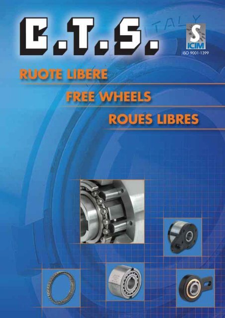
RUOTE LIBERE<br />
Le ruote libere a rulli consistono di una parte esterna con superficie interna di scorrimento circolare, di una<br />
parte interna con segmenti di contatto disposti a stella ed inoltre di più corpi di contatto singolarmente molleggiati<br />
dall’anello interno. Nell’ambito del numero di giri consentito detti rulli rimangono costantemente in contatto<br />
sia con la parte interna, che con quella esterna. In questo modo le ruote libere a rulli sono sempre pronte<br />
all’inserzione - le ruote libere si inseriscono con presa immediata, non appena la parte interna o quella<br />
esterna vengano girate in senso contrario l’una rispetto all’altra.<br />
Inoltre, a seconda del momento torcente da trasmettere, dopo l’inserimento si avrà una deformazione elastica<br />
di tutte le parti che sono coinvolte nella trasmissione del momento torcente, deformazione che avrà come<br />
conseguenza un ritardo di avanzamento.<br />
Le ruote libere a rulli possono essere impiegate come supero di velocità, come antiritorno oppure come avanzamento<br />
intermittente. L’attribuzione specifica della funzione da svolgere avviene prima di tutto a seconda del<br />
numero degli avanzamenti intermittenti previsti e dei momenti torcenti da trasmettere, tenendo conto del massimo<br />
numero di giri (differenza del numero di giri tra la parte interna ed esterna, rispettivamente tra la parte<br />
esterna ed interna).<br />
Supero di velocità<br />
Le ruote libere a rulli, qualora impiegate come supero di velocità, debbono essere disposte in modo tale che<br />
nel campo di supero la parte interna sia ferma o si muova lentamente e la parte esterna superi. Questa disposizione<br />
consente un più alto numero di giri di supero, riduce l’usura ed il surriscaldamento, allungando così<br />
la vita alla ruota libera di supero.<br />
Antiritorno<br />
Se le ruote vengono impiegate come antiritorno, il numero di giri di supero può normalmente essere affidato<br />
solamente alla parte interna, in questo caso si debbono rispettare i giri di supero massimi consentiti indicati<br />
nelle pagine seguenti e per una buona lubrificazione si consiglia l’impiego di olio a bassa viscosità, possibilmente<br />
lubrificazione a circolazione d’olio.<br />
Avanzamento intermittente<br />
Qualora impiegate come elementi di avanzamento intermittente, le ruote libere affideranno detto avanzamento<br />
intermittente alla parte esterna, mentre la trasmissione avverà tramite l’anello interno. Una sola ruota<br />
libera è già di per sé un avanzamento intermittente completo, in questo caso però è possibile solo un movimento<br />
rotatorio della trasmissione interrotto, durante il quale i tempi di avanzamento corrispondono esattamente<br />
ai tempi morti (funzionamento a vuoto durante il movimento di ritorno). Impiegando due o più ruote libere<br />
azionate alternativamente (ad esempio mediante cammes) si otterrà un movimento di rotazione della trasmissione<br />
continuato, anche se leggermente ondulato.<br />
Elevate precisioni<br />
Qualora vengano richiesti avanzamenti molto precisi, è possibile, anzi consigliabile, munire le ruote libere a<br />
rulli di un molleggio rinforzato (reperibile presso di noi in breve tempo). Si consiglia inoltre di impiegare un olio<br />
lubrificante molto fluido e l’ulteriore sistemazione di un antiritorno sull’albero di trasmissione. Impiegando le<br />
ruote libere come elementi di avanzamento intermittente è necessario a volte tenere presente i ritardi di avanzamento<br />
causati da una deformazione elastica, che sono differenti a seconda delle singole grandezze, ma<br />
proporzionali all’intensità di carico. Tali ritardi si possono ulteriormente ridurre applicando sottopiani in metallo<br />
duro (HM) disponibili nella serie GL (GL...HM).<br />
2
Come operare la scelta<br />
Ruote libere da centrare<br />
I tipi US, USNU, ed UF, impiegati come avanzamento intermittente, antiritorno oppure supero di velocità vengono<br />
normalmente sistemati all’interno di carter chiusi (ingranaggi, coperture terminali, ecc.) vicino a cuscinetti<br />
preesistenti o aggiunti successivamente. Pertanto le parti interne ed esterne debbono essere perfettamente<br />
centrate l’una rispetto all’altra; in senso assiale non debbono essere né caricate né sottoposte a tensione.<br />
Nel pressare o nell’estrarre agire simultaneamente sia sulla parte esterna che su quella interna onde<br />
evitare il danneggiamento dei corpi di contatto e delle molle. Per lubrificare queste ruote libere può essere sufficiente<br />
una circolazione d’olio già preesistente, qualora il tipo d’olio impiegato rientri in quelli consigliati da noi<br />
per le ruote libere a rulli.<br />
Ruote libere autocentranti<br />
I tipi GF (grandezze 8...20) e GV hanno bronzine; i tipi GF (grandezze 25...130) hanno cuscinetti a sfere.<br />
I tipi GF vengono impiegati come elementi di avanzamento intermittente, antiritorno e supero di velocità per<br />
lo più all’interno di carter chiusi. Per lubrificare queste ruote libere può bastare una circolazione d’olio già preesistente<br />
qualora il tipo d’olio impiegato rientri in quelli consigliati da noi per le ruote libere a corpi di contatto<br />
cilindrici. I tipi GV vengono impiegati come ritorno o avanzamento intermittente all’esterno di carter liberamente<br />
installati su alberi di trasmissione con trasmissione del momento torcente affidato alla leva saldata sull’anello<br />
esterno. Questi tipi vengono da noi forniti con grasso for-life e relativa guarnizione.<br />
Ruote libere modulari con cuscinetti a sfera<br />
Tra l’anello interno e quello esterno sono montati due cuscinetti a sfera scanalati della serie 160.<br />
Per quanto riguarda la durata valgono le disposizioni del costruttore dei cuscinetti.<br />
I tipi base GL e GLP formano, assieme ad una vasta serie di coperchi e flange standard o speciali, unità complete<br />
dotate di sistema di lubrificazione autonomo.<br />
Queste ruote libere vengono usate come elementi di avanzamento intermittente, antiritorno o supero di velocità<br />
(molto spesso in abbinamento a giunti elastici) per lo più all’esterno di carter (ad es. in pulegge o terminali<br />
d’albero). All’interno di carter possono essere inserite come ruote libere di base oppure essere collegate<br />
ad un circuito di lubrificazione preesistente complete di coperchio e flangia (in questo caso senza anelli tenuta<br />
olio), sempre qualora il tipo di olio impiegato rientri in quelli consigliati da noi per le ruote libere a corpi di<br />
contatto cilindrici.<br />
Normalmente le ruote libere di base e loro componenti (coperchio, flangia, guarnizioni e viti) vengono fornite<br />
smontate.<br />
Se ci date il senso di rotazione richiesto, possiamo sistermarvi i pezzi già pronti per il montaggio. Vogliate<br />
tenere presente le seguenti definizioni:<br />
Senso di rotazione destro (R): guardando il coperchio D la parte interna della ruota libera gira a vuoto in senso<br />
orario.<br />
Senso di rotazione sinistro (L): guardando il coperchio D la parte interna della ruota libera gira a vuoto in senso<br />
antiorario.<br />
Applicazioni speciali<br />
Siamo a vostra disposizione per la soluzione dei problemi più disparati, sottoponendovi modifiche e misure tra<br />
le più diverse. Per queste soluzioni desideriamo consigliarvi personalmente.<br />
3
FREEWHEELS:<br />
The roller type freewheels consist of an external component with an internal circular sliding surface, an internal<br />
component with contact segments arranged in a star configuration and also multiple contact elements,<br />
each sprung by the inner race. Within the number of rotations allowed, these rollers remain constantly in contact<br />
with both the internal and external components. This allows the roller freewheels to be always ready for<br />
insertion – freewheel components are located immediately as soon as the internal or external components are<br />
turned in the opposite direction to each other.<br />
In addition, according to the torque loading to be transmitted, after insertion, all the components that transmit<br />
the torque load will be subjected to elastic deformation, resulting in a feed delay.<br />
Roller freewheels may be used for overspeed, non-return or intermittent feed applications. The specific function<br />
required depends on the number of intermittent feeds required and on the torque loads to be transmitted,<br />
taking into account the highest number of rotations (the difference between the number of internal to external<br />
component rotations in relation to the number of external to internal component rotations).<br />
Overspeed<br />
Roller type freewheels, when used for overspeed applications must be positioned in such a way that, in the<br />
overspeed range, the internal freewheel component is stationary or rotates slowly and the external component<br />
overspeeds. This layout ensures a higher number of overspeed rotations, reduces wear and overheating<br />
and increases the life of the overspeed freewheel.<br />
Non-return<br />
If the freewheels are used for non-return applications, the number of overspeed rotations can normally only<br />
be performed by the internal component. In this case, the maximum number of overspeed rotations shown in<br />
the following pages must be adhered to and, to ensure good lubrication, a low viscosity oil should be used,<br />
preferably oil circulation lubrication.<br />
Intermittent Feed<br />
When used for intermittent feed applications, the intermittent feed will be performed by the external component,<br />
whilst transmission will be performed by the inner race. One freewheel is already a complete intermittent<br />
feed unit but, in this case, only an interrupted rotating movement from the transmission is possible, during<br />
which the feed periods are exactly the same as the stationary periods (idling during the return movement). By<br />
using two or more freewheels with alternating operation (i.e. by means of cams), a continuous rotation transmission<br />
movement will be achieved, although slightly uneven.<br />
High Accuracy<br />
When very accurate feed applications are required, it is possible, and highly recommended, to add a reinforced<br />
spring to roller type freewheels (these can be supplied with a quick turn-round). It is also recommended<br />
that lubricating oil with very high fluidity is used and a non-return is fitted on the drive shaft. When using freewheels<br />
as intermittent feed elements, the feed delay caused by elastic deformation must be considered.<br />
These are different according to each dimension but are directly proportioned to the load. The delays can be<br />
reduced further by applying under plates made from hard metal (HM) available in the GL (GL .... HM) Series.<br />
4
Selection Guide<br />
Freewheels requiring centring<br />
US, USNU and UF Series freewheels used for intermittent feed, non-return or overspeed applications are<br />
generally placed inside closed guards (gears, end covers, etc..) in proximity to pre-existing bearings or<br />
additional bearings. The external and internal components must therefore be centred to each other; in the<br />
axial direction, they must not be under load or in tension. When pressing or extracting, simultaneously apply<br />
pressure both on the internal and external parts to avoid damage to the contact elements and springs. To<br />
lubricate this range of freewheels, a pre-existing oil circulation may be sufficient, provided the type of oil used<br />
is one of the recommended types for roller type freewheels.<br />
Self-centring Freewheels<br />
The GF Series (sizes 8…20) and GV Series are bushed; the GF Series (sizes 25…130) have ball bearings.<br />
The GF Series are used as intermittent feed, non-return and overspeed units mainly inside closed guards. To<br />
lubricate this range of freewheels, a pre-existing oil circulation may be sufficient, provided the type of oil used<br />
is one of those we recommend for cylindrical element contact units. The GV Series are used for return or<br />
intermittent feed applications and are located outside guards on drive shafts where the transmission torque is<br />
provided by the lever welded on the outer race. These types are supplied greased-for-life and with gasket.<br />
Modular Freewheels with Ball-bearings<br />
Modular freewheels consist of two 160 Series slotted ball bearings fitted between the inner and outer race.<br />
For information regarding working life of the units, see the instructions given by the bearing manufacturer.<br />
Together with a wide range of standard or special covers or flanges, the basic GL and GLP types form<br />
complete units with an incorporated self-lubricating system.<br />
These freewheels are used for intermittent feed, non-return or overspeed unit applications (very often with<br />
flexible joints) mainly located outside guards (i.e. mounted on pulleys or shaft ends). Inside the guards, they<br />
can be utilised as basic freewheels or can be connected to an existing lubrication circuit complete with cover<br />
and flange (in this case, without oil seal rings) as long as the type of oil used is one of those we recommend<br />
for freewheels with cylindrical element contact units. Normally, basic freewheels and their components (cover,<br />
flange, gaskets and screws) are supplied unassembled. If the required direction of rotation is supplied, we can<br />
provide you with the parts ready for assembly. Please consider the following definitions:<br />
Right rotation direction (R): When looking at cover D, the internal freewheel component idles clockwise.<br />
Left rotation direction (L): When looking at cover D, the internal freewheel component idles anti-clockwise.<br />
Special Applications<br />
We are happy to provide you with any solution you may require by offering you the widest range of<br />
modifications and dimensions. For this type of solution, we prefer to talk to you personally.<br />
5
ROUES LIBRES:<br />
Les roues libres à rouleaux consistent en une partie externe présentant une surface de coulissement interne<br />
circulaire, d'une partie interne munie de segments de contact disposés en étoile et de plusieurs corps de contact<br />
suspendus séparément sur la bague interne. Selon le nombre de tours admissible, ces rouleaux restent<br />
constamment en contact aussi bien avec la partie interne qu'avec la partie externe. De cette manière, les<br />
roues libres à rouleaux sont toujours prêtes à l'insertion - les roues libres s'insèrent avec une prise immédiate,<br />
dès que la partie interne et la partie externe tournent dans le sens inverse des aiguilles d'une montre l'une<br />
par rapport à l'autre.<br />
En outre, en fonction du moment de torsion à transmettre, après l'insertion, on assiste à une déformation élastique<br />
de toutes les pièces impliquées dans la transmission du moment de torsion, déformation qui entraîne<br />
un retard de l'avance.<br />
Les roues libres à rouleaux peuvent être utilisées en tant qu'éléments de dépassement de vitesse, d'antiretour<br />
ou d'avance intermittente. L'attribution spécifique de la fonction à accomplir se fait tout d'abord en fonction<br />
du nombre d'avances intermittentes prévues et des moments de torsion à transmettre, en tenant comte<br />
du nombre maximal de tours (différence entre le nombre de tours de la partie interne et celui de la partie externe,<br />
respectivement entre la partie externe et la partie interne).<br />
Dépassement de vitesse<br />
Lorsqu'elles sont utilisées en tant qu'éléments de dépassement de vitesse, les roues libres à rouleaux doivent<br />
être disposées de façon à ce que, dans le champ de dépassement, la partie interne soit arrêtée ou ne se<br />
déplace que lentement et que la partie externe la dépasse. Cette disposition garantit un nombre supérieur de<br />
tours de dépassement, elle réduit l'usure et la surchauffe, ce qui permet d'allonger la durée du cycle de vie<br />
de la roue libre de dépassement.<br />
Anti-retour<br />
Si les roues sont utilisées en tant qu'éléments d'anti-retour, le nombre de tours de dépassement peut, normalement,<br />
être assuré uniquement par la partie interne. Dans ce cas, il est nécessaire de respecter le nombre<br />
de tours maximal admissible qui est indiqué dans les prochaines pages. Pour garantir une bonne lubrification,<br />
il est conseillé d'utiliser de l'huile à bas niveau de viscosité et de recourir, si possible, à un système de<br />
lubrification à recirculation d'huile.<br />
Avance intermittente<br />
Si elles sont utilisées en tant qu'éléments d'avance intermittente, les roues libres font exécuter cette avance<br />
par la partie externe, tandis que la transmission sera exécutée au moyen de la bague interne. A elle seule,<br />
une roue libre constitue déjà une avance intermittente complète. Toutefois, dans ce cas, il n'est possible de<br />
réaliser qu'un mouvement rotatoire interrompu de la transmission, au cours duquel les temps d'avance correspondent<br />
exactement aux temps morts (fonctionnement à vide pendant le mouvement de retour). En utilisant<br />
deux ou plusieurs roues libres actionnées alternativement (par exemple, au moyen de cames), on obtient<br />
un mouvement rotatoire continu, mais légèrement ondulé, de la transmission.<br />
Précisions de haut niveau<br />
Lorsque les avances doivent être très précises, il est possible, voire conseillé, de munir les roues libres à rouleaux<br />
d'une suspension renforcée (que nous pouvons fournir rapidement). Il est également conseillé d'utiliser<br />
une huile lubrifiante très fluide et d'installer un dispositif d'anti-retour sur l'arbre de transmission. Lorsque l'on<br />
utilise les roues libres en tant qu'éléments d'avance intermittente, il est parfois nécessaire de tenir compte des<br />
retards d'avance dus à une déformation élastique. Ces retards diffèrent en fonction des différentes grandeurs,<br />
mais ils sont proportionnels à l'intensité de charge et peuvent être réduits en appliquant des dessous de plan<br />
réalisés avec un métal dur (HM) et disponibles dans la série GL (GL…HM).<br />
6
Comment faire son choix<br />
Roues libres à centrer<br />
Habituellement, les types US, USNU et UF, utilisés en tant qu'éléments d'avance intermittente, d'anti-retour<br />
ou de dépassement de vitesse sont installés à l'intérieur de carters fermés (engrenages, couvertures finales,<br />
etc.), près de roulements préexistants ou ajoutés dans un deuxième temps. La partie interne et la partie<br />
externe doivent donc être parfaitement centrées l'une par rapport à l'autre. Dans le sens axial, elles ne doivent<br />
être ni chargées, ni soumises à tension. Lors du pressage ou de l'extraction, agir en même temps aussi bien<br />
sur la partie externe que sur la partie interne, de façon à ne pas abîmer les corps de contact et les ressorts.<br />
Pour lubrifier ces roues libres, la circulation de l'huile préexistante peut suffire, à condition que l'huile utilisée<br />
fasse partie de celles que nous recommandons pour les roues libres à rouleaux.<br />
Roues libres autocentreuses<br />
Les types GF (grandeur 8……20) et GV ont des coussinets en bronze, tandis que les types GF (grandeur<br />
25…..130) ont des roulements à billes. Les types GF sont utilisés en tant qu'éléments d'avance intermittente,<br />
d'anti-retour ou de dépassement de vitesse qui, pour la plupart, sont situés à l'intérieur de carters fermés. Pour<br />
lubrifier ces roues libres, la circulation de l'huile préexistante peut suffire, à condition que l'huile utilisée<br />
compte au nombre de celles que nous recommandons pour les roues libres à corps de contact cylindriques.<br />
Les types GV sont utilisés en tant qu'éléments de retour ou d'avance intermittente à l'extérieur de carters<br />
installés librement sur les arbres de transmission, avec transmission du moment de torsion assurée par le<br />
levier soudé sur la bague externe. Nous fournissons ces articles graissés à vie et munis de leur propre joint.<br />
Roues libres modulaires à roulements à billes<br />
Deux roulements à billes cannelés de la série 160 sont montés entre la bague interne et la bague externe.<br />
Pour ce qui est de la durée s’en tenir aux dispositions du fabricant des roulements.<br />
Munis de toute une série de couvercles et de brides standards ou spéciales, les types de base GL et GLP<br />
forment des unités complètes et disposant d'un système de lubrification autonome.<br />
Ces roues libres sont utilisées en tant qu'éléments d'avance intermittente, d'anti-retour ou de dépassement<br />
de vitesse (très souvent associés à des joints élastiques) qui, pour la plupart, sont situés à l'extérieur de<br />
carters (par ex. sur des poulies ou des pièces terminales de l'arbre). A l'intérieur des carters, elles peuvent<br />
être insérées en tant que roues libres de base ou être raccordées à un circuit de lubrification préexistant et<br />
munies d'un couvercle et d'une bride (dans ce cas, elles sont sans bague d'étanchéité d'huile). Il va de soi<br />
que le type d'huile utilisé doit faire partie des huiles que nous recommandons pour les roues libres à corps de<br />
contact cylindriques.<br />
Habituellement, les roues libres de base et leurs composants (couvercle, bride, joints et vis) sont fournis<br />
démontés. Toutefois, au cas où le client nous indiquerait le sens de rotation voulu, il est possible de livrer les<br />
pièces prêtes au montage. Le client est alors prié de tenir compte des définitions suivantes:<br />
Sens de rotation à droite (R): en regardant le couvercle D, la partie interne de la roue libre tourne à vide dans<br />
le sens des aiguilles d'une montre.<br />
Sens de rotation à gauche (L): en regardant le couvercle D, la partie interne de la roue libre tourne à vide dans<br />
le sens inverse des aiguilles d'une montre.<br />
Applications spéciales<br />
Nous nous tenons à la disposition du client pour l'aider à résoudre les problèmes les plus disparates, lui<br />
proposer les modifications et les mesures les plus diverses. Pour toutes ces solutions, nous préférons vous<br />
conseiller personnellement.<br />
7
Tipo, Type, Modèle US<br />
Le ruote libere della serie US non<br />
sono autocentrate.<br />
È pertanto necessario disporre a<br />
fianco della ruota libera uno o<br />
due cuscinetti in modo che<br />
l’anello esterno ruoti centrato<br />
rispetto a quello interno.<br />
Le US hanno le stesse<br />
dimensioni dei cuscinetti a sfere<br />
serie 62.<br />
I momenti torcenti vengono<br />
trasmessi dall’albero all’anello<br />
interno mediante la chiavetta e<br />
dall’anello esterno<br />
all’alloggiamento per<br />
l’interferenza generata dalla<br />
tolleranza J6 del diametro<br />
esterno.<br />
Le tolleranze per l’albero<br />
dovranno essere h6 oppure j7,<br />
quelle per l’alloggiamento H7<br />
oppure J6.<br />
Le ruote libere, prima della<br />
messa in funzione, debbono<br />
essere lubrificate secondo<br />
quanto raccomandato a pag. 49<br />
con lubrificanti adeguati.<br />
La lubrificazione con olio é<br />
indispensabile qualora si<br />
raggiunga un elevato numero di<br />
giri in folle.<br />
The US Series freewheels are<br />
not self-centring. It is therefore<br />
required to place one or two<br />
bearings next to the freewheel so<br />
that the outer race can rotate<br />
centrally to the inner race.<br />
US freewheels have ball bearings<br />
with the same dimensions as the<br />
62.. Series.<br />
The torque forces are transmitted<br />
from the shaft to the inner race<br />
by means of a key and from the<br />
outer race to the seating by<br />
means of an interference fit on<br />
the R6 tolerance of the external<br />
diameter.<br />
Shaft tolerance must be either h6<br />
or j7; the tolerances for the<br />
seating must be either H7<br />
or J6.<br />
Before being put onto service,<br />
the freewheels must be<br />
lubricated with suitable lubricants<br />
following the instructions given<br />
on page 49. Oil lubrication is<br />
essential when a high number of<br />
rotations in neutral is reached.<br />
Les roues libres de la série US<br />
ne sont pas autocentrées. Il est<br />
donc nécessaire de placer un ou<br />
deux roulements à côté de la<br />
roue libre, de façon à ce que la<br />
bague externe tourne en étant<br />
centrée par rapport à la bague<br />
interne.<br />
Les USNU présentent les mêmes<br />
dimensions que les roulements à<br />
bille de la série 62.<br />
Les moments de torsion sont<br />
transmis de l'arbre à la bague<br />
interne par l'intermédiaire<br />
de la clavette et, de la bague<br />
externe au logement, par<br />
l'interférence générée par la<br />
tolérance r6 du diamètre externe.<br />
Pour l'arbre, les tolérances<br />
doivent être h6 ou j7. Pour le<br />
logement, ces tolérances doivent<br />
être H7 ou J6.<br />
Avant la mise en marche, les<br />
roues libres doivent être<br />
lubrifiées selon les consignes<br />
présentées page 49 et avec des<br />
lubrifiants appropriés. La<br />
lubrification à l'huile est<br />
indispensable lorsque le nombre<br />
de tours est élevé en marche à<br />
vide.<br />
8
Tipo, Type, Modèle US<br />
Tipo<br />
Type d H7 D r6 L D 2 s<br />
Modèle<br />
Peso n MAX (min -1 ) n MAX (min -1 ) Coppia resist. in folle<br />
Weight<br />
Masse<br />
Anello interno<br />
Inner race<br />
Anello esterno<br />
Outer race<br />
T N<br />
Resistance torque<br />
Couple résiduel<br />
Kg Bague intèrne Bague extèrne Nm<br />
US 8 8 24 8 19 1 0,03 4350 6600 3,8 0,003<br />
US 10 10 30 9 25 1 0,04 3550 5200 6,8 0,004<br />
US 12 12 32 10 26 1 0,05 3200 4850 13 0,005<br />
US 15 15 35 11 30 1 0,10 2900 4300 14 0,007<br />
US 17 17 40 12 34 1 0,11 2600 3700 28 0,01<br />
US 20 20 47 14 40 1 0,12 2200 3300 40 0,02<br />
US 25 25 52 15 45 1 0,15 2000 2900 56 0,03<br />
US 30 30 62 16 55 1 0,25 1600 2500 90 0,08<br />
US 35 35 72 17 62 1 0,33 1350 2000 150 0,09<br />
US 40 40 80 18 70 1 0,42 1200 1900 185 0,10<br />
US 45 45 85 19 74 1 0,46 1100 1650 218 0,11<br />
US 50 50 90 20 80 1 0,50 900 1450 230 0,13<br />
US 55 55 100 21 90 1 0,65 800 1300 313 0,14<br />
US 60 60 110 22 98 1 0,80 700 1100 513 0,26<br />
Note<br />
T MAX = 2 x T N<br />
Cava US 8-12 DIN 6885 foglio 1<br />
Cava US 15-60 DIN 6885 foglio 3<br />
Notes<br />
T MAX = 2 x T N<br />
Keyway US 8-12 DIN 6885 page 1<br />
Keyway US 15-60 DIN 6885 page 3<br />
Remaques<br />
T MAX = 2 x T N<br />
Rainure US 8-12 DIN 6885 page 1<br />
Rainure US 15-60 DIN 6885 page 3<br />
s/ 2<br />
s/ 2<br />
d H7<br />
D 2<br />
D r6<br />
L<br />
Esempio di montaggio<br />
Mounting example<br />
Exemple de montage<br />
9
Tipo, Type, Modèle USNU<br />
Le ruote libere della serie USNU<br />
non sono autocentrate.<br />
È pertanto necessario disporre a<br />
fianco della ruota libera uno o<br />
due cuscinetti in modo che<br />
l’anello esterno ruoti centrato<br />
rispetto a quello interno.<br />
Le USNU hanno le stesse<br />
dimensioni dei cuscinetti a sfere<br />
serie 63..<br />
I momenti torcenti vengono<br />
trasmessi dall’albero all’anello<br />
interno mediante la chiavetta, e<br />
dall’anello esterno<br />
all’alloggiamento mediante<br />
trascinatori frontali o per<br />
interferenza se l’alloggiamento è<br />
in tolleranza K6.<br />
Le tolleranze per l’albero<br />
dovranno essere h6 oppure j7,<br />
quelle per l’alloggiamento H7<br />
oppure F7.<br />
Qualora non si usassero<br />
trascinatori frontali la tolleranza<br />
per l’alloggiamento diventa K6.<br />
Le ruote libere, prima della<br />
messa in funzione, debbono<br />
essere lubrificate secondo<br />
quanto raccomandato a pag. 49<br />
con lubrificanti adeguati.<br />
La lubrificazione con olio è<br />
indispensabile qualora si<br />
raggiunga un elevato numero di<br />
giri in folle.<br />
The USNU Series freewheels are<br />
not self-centring.<br />
It is therefore necessary to place<br />
one or two bearings next to the<br />
freewheel so that the outer race<br />
can rotate centrally to the inner<br />
race.<br />
USNU freewheels have ball<br />
bearings with the same<br />
dimensions as the 63.. Series.<br />
The torque forces are transmitted<br />
from the shaft to the inner race<br />
by means of a key and from the<br />
outer race to the seating by<br />
means of front pullers or by<br />
means of an interference fit if the<br />
seating tolerance is made a K6.<br />
Shaft tolerance must be either h6<br />
or j7; the tolerances for the<br />
seating must be either H7 or F7.<br />
When front pullers are not used,<br />
the seating tolerance should be<br />
K6.<br />
Before being put onto service,<br />
the freewheels must be<br />
lubricated with suitable lubricants<br />
following the instructions given<br />
on page 49. Oil lubrication is<br />
essential when a high number of<br />
rotations in neutral is reached.<br />
Les roues libres de la série<br />
USNU ne sont pas autocentrées. Il<br />
est donc nécessaire de placer un<br />
ou deux roulements à côté de la<br />
roue libre, de façon à ce que la<br />
bague externe tourne en étant<br />
centrée par rapport à la bague<br />
interne.<br />
Les USNU présentent les mêmes<br />
dimensions que les roulements à<br />
bille de la série 63.<br />
Les moments de torsion sont<br />
transmis de l'arbre à la bague<br />
interne par l'intermédiaire de la<br />
clavette et, de la bague externe<br />
au logement, par l'intermédiaire<br />
des entraîneurs frontaux ou par<br />
interférence si la tolérance du<br />
logement est K6.<br />
Pour l'arbre, les tolérances<br />
doivent être h6 ou j7. Pour le<br />
logement, ces tolérances doivent<br />
être H7 ou G7.<br />
Si l'on n'utilise pas d'entraîneurs<br />
frontaux, pour le logement, la<br />
tolérance devient K6.<br />
Avant la mise en marche, les<br />
roues libres doivent être<br />
lubrifiées selon les consignes<br />
présentées page 49 et avec des<br />
lubrifiants appropriés. La<br />
lubrification à l'huile est<br />
indispensable lorsque le nombre<br />
de tours est élevé en marche à<br />
vide.<br />
10
Tipo, Type, Modèle USNU<br />
Tipo<br />
Type<br />
Modèle<br />
Peso n MAX (min -1 ) 1) n MAX (min -1 ) 2) Coppia resist. in folle<br />
d H7 D n6 L s D 2 b t Weight Anello interno Anello esterno T N Resistance torque<br />
mm mm mm mm mm mm mm Masse Inner race Outer race Nm Couple résiduel<br />
Kg Bague intèrne Bague extèrne Nm<br />
USNU 8 8 35 13 1 27 4 1,3 0,1 3300 5000 12 0,016<br />
USNU 12 12 35 13 1 27 4 1,3 0,1 3300 5000 12 0,016<br />
USNU 15 15 42 18 1 36 5 1,3 0,1 2500 3600 30 0,02<br />
USNU 17 17 47 19 1 36 5 2 0,1 2300 3400 50 0,02<br />
USNU 20 20 52 21 1 44 6 2,5 0,2 2200 3100 78 0,02<br />
USNU 25 25 62 24 1 52 8 2 0,4 1700 2200 125 0,05<br />
USNU 30 30 72 27 1 60 10 3 0,6 1400 2200 255 0,14<br />
USNU 35 35 80 31 1 70 12 3,5 0,7 1200 1900 383 0,16<br />
USNU 40 40 90 33 1 78 12 3,5 0,9 1100 1700 545 0,40<br />
USNU 45 45 100 36 2 85 14 3,5 1,2 1000 1600 788 0,45<br />
USNU 50 50 110 40 2 92 14 4,5 1,7 900 1300 1013 0,50<br />
USNU 60 60 130 46 2 110 18 5,5 2,8 700 1100 1835 1,1<br />
USNU 70 70 150 51 2 125 20 6,5 4 600 1000 2312 1,5<br />
USNU 80 80 170 58 2 140 20 7,5 5,8 500 800 3300 1,8<br />
Note<br />
T MAX = 2 x T N<br />
Cava US 8-12 DIN 6885 foglio 1<br />
Cava US 15-80 DIN 6885 foglio 3<br />
1) Anello interno più veloce dall’anello<br />
esterno<br />
2) Anello esterno più veloce dell’anello<br />
interno<br />
Notes<br />
T MAX = 2 x T N<br />
Keyway USNU 8-12 DIN 6885 page 1<br />
Keyway USNU 15-80 DIN 6885 page 3<br />
1) Inner race is faster than the outer race<br />
2) Outer race is faster than the inner race<br />
Remarques<br />
T MAX = 2 x T N<br />
Rainure USNU 8-12 DIN 6885 feuille 1<br />
Rainure USNU 15-80 DIN 6885 feuille 3<br />
1) Bague interne plus rapide que la<br />
bague externe<br />
2) Bague externe plus rapide que la<br />
bague interne<br />
s/ 2 s/ 2<br />
b<br />
d H7<br />
D 2<br />
D n6<br />
t<br />
t<br />
L<br />
Esempio di montaggio<br />
Mounting example<br />
Exemple de montage<br />
11
Tipo, Type, Modèle UF<br />
Le ruote libere della serie UF<br />
non sono autocentrate.<br />
È pertanto necessario disporre a<br />
fianco della ruota libera uno o<br />
due cuscinetti in modo che<br />
l’anello esterno ruoti centrato<br />
rispetto a quello interno.<br />
I momenti torcenti vengono<br />
trasmessi dall’albero all’anello<br />
interno mediante la chiavetta, e<br />
dall’anello esterno<br />
all’alloggiamento mediante<br />
trascinatori frontali.<br />
Le tolleranze per l’albero<br />
dovranno essere h6 oppure j6,<br />
quelle per l’alloggiamento H7<br />
oppure G7.<br />
Qualora non si usassero<br />
trascinatori frontali la tolleranza<br />
per l’alloggiamento diventa K6.<br />
Le ruote libere, prima della<br />
messa in funzione, debbono<br />
essere lubrificate secondo<br />
quanto raccomandato a pag. 49<br />
con lubrificanti adeguati.<br />
La lubrificazione con olio è<br />
indispensabile qualora si<br />
raggiunga un elevato numero di<br />
giri in folle.<br />
The UF Series freewheels are<br />
not self- centring. It is therefore<br />
necessary to place one or two<br />
bearings next to the freewheel so<br />
that the outer race can rotate<br />
centrally to the inner race.<br />
The torque forces are transmitted<br />
from the shaft to the inner race<br />
by means of a key and from the<br />
outer race to the seating by<br />
means of front pullers.<br />
Shaft tolerance must be either h6<br />
or j6; the tolerances for the<br />
seating must be either H7 or G7.<br />
When front pullers are not used,<br />
the seating tolerance should be<br />
K6.<br />
Before being put onto service,<br />
the freewheels must be<br />
lubricated with suitable lubricants<br />
following the instructions given<br />
on page 49. Oil lubrication is<br />
essential when a high number of<br />
rotations in neutral is reached.<br />
Les roues libres de la série UF<br />
ne sont pas autocentrées. Il est<br />
donc nécessaire de placer un ou<br />
deux roulements à côté de la<br />
roue libre, de façon à ce que la<br />
bague externe tourne en étant<br />
centrée par rapport à la bague<br />
interne.<br />
Les moments de torsion sont<br />
transmis de l'arbre à la bague<br />
interne par l'intermédiaire de la<br />
clavette et, de la bague externe<br />
au logement par l'intermédiaire<br />
des entraîneurs frontaux.<br />
Pour l'arbre, les tolérances<br />
doivent être h6 ou j6. Pour le<br />
logement, ces tolérances doivent<br />
être H7 ou G7.<br />
Si l'on n'utilise pas d'entraîneurs<br />
frontaux, pour le logement, la<br />
tolérance devient K6.<br />
Avant la mise en marche, les<br />
roues libres doivent être<br />
lubrifiées selon les consignes<br />
présentées page 49 et avec des<br />
lubrifiants appropriés. La<br />
lubrification à l'huile est<br />
indispensable lorsque le nombre<br />
de tours est élevé en marche à<br />
vide.<br />
12
Tipo, Type, Modèle UF<br />
Tipo<br />
Type<br />
Modèle<br />
Peso n MAX (min -1 ) 1) n MAX (min -1 ) 2) Coppia resist. in folle<br />
d H7 D h6 L s D 1 D 2 b t Weight Anello interno Anello esterno T N Resistance torque<br />
mm mm mm mm mm mm mm mm Masse Inner race Outer race Nm Couple résiduel<br />
Kg Bague intèrne Bague extèrne Nm<br />
UF 8 8 37 20 1 20 30 6 3 0,1 5000 6000 20 0,09<br />
UF 9 9 37 20 1 20 30 6 3 0,1 5000 6000 20 0,09<br />
UF 12 12 37 20 1 20 30 6 3 0,1 5000 6000 20 0,11<br />
UF 15 15 47 30 1 26 37 7 3,5 0,3 4500 5500 78 0,15<br />
UF 20 20 62 36 1 37 52 8 3,5 0,6 3000 3600 188 0,18<br />
UF 25 25 80 40 2 40 68 9 4 1,1 2200 2600 250 0,36<br />
UF 30 30 90 48 2 45 75 12 5 1,6 1800 2100 500 0,40<br />
UF 35 35 100 53 2 50 80 13 6 2,3 1600 2000 680 0,60<br />
UF 40 40 110 63 2 55 90 15 7 3,1 1300 1700 1115 0,84<br />
UF 45 45 120 63 2 60 95 16 7 3,7 1100 1500 1500 0,94<br />
UF 50 50 130 80 2 70 110 17 8,5 5,4 850 1300 2375 1,28<br />
UF 55 55 140 80 2 75 115 18 9 6,1 800 1200 2500 1,50<br />
UF 60 60 150 95 2 80 125 18 9 8,5 700 1100 4250 1,60<br />
UF 70 70 170 110 3 95 140 20 9 13 550 900 5875 3,60<br />
UF 80 80 190 125 3 110 160 20 9 18 620 800 10000 3,60<br />
UF 90 90 215 140 3 120 180 24 11,5 25,3 500 700 17350 6,80<br />
UF 100 100 260 150 4 140 210 28 14,5 42,1 400 600 19750 8,80<br />
UF 130 130 300 180 4 160 240 32 17,5 65 300 500 35000 12,50<br />
UF 150 150 320 180 4 205 260 32 17 95 250 400 44400 13,50<br />
Note<br />
T MAX = 2 x T N<br />
DIN 6885 foglio 1<br />
1) Anello interno più veloce dall’anello<br />
esterno<br />
2) Anello esterno più veloce dell’anello<br />
interno<br />
Notes<br />
T MAX = 2 x T N<br />
Keyway DIN 6885 page 1<br />
1) Inner race is faster than touter race<br />
2) Outer race is faster than inner race<br />
Remarques<br />
T MAX = 2 x T N<br />
Rainure DIN 6885 page 1<br />
1) Bague interne plus rapide que la<br />
bague externe<br />
2) Bague externe plus rapide que la<br />
bague interne<br />
b<br />
D2<br />
D1<br />
s/ 2 s/ 2<br />
t<br />
d H7<br />
Dh6<br />
t<br />
L<br />
Esempio di montaggio<br />
Mounting example<br />
Exemple de montage<br />
13
Tipo, Type, Modèle GF<br />
Le ruote libere della serie GF<br />
sono autocentrate.<br />
Dalla misura 8 alla 20 il<br />
centraggio è acciaio su acciaio<br />
mentre dalla 25 alla 130 ciò<br />
viene assicurato da 2 cuscinetti<br />
della serie 160.<br />
I momenti torcenti vengono<br />
trasmessi dall’albero all’anello<br />
interno mediante la chiavetta, e<br />
dall’anello esterno<br />
all’alloggiamento mediante<br />
trascinatori frontali.<br />
Le tolleranze per l’albero<br />
dovranno essere h6 oppure j6,<br />
quelle per l’alloggiamento H7<br />
oppure G7.<br />
Qualora non si usassero<br />
trascinatori frontali la tolleranza<br />
per l’alloggiamento diventa K6.<br />
Le ruote libere, prima della<br />
messa in funzione, debbono<br />
essere lubrificate secondo<br />
quanto raccomandato a pag. 49<br />
con lubrificanti adeguati.<br />
La lubrificazione con olio è<br />
indispensabile qualora si<br />
raggiunga un elevato numero di<br />
giri in folle.<br />
The GF Series freewheels are<br />
self centring. From size 8 to size<br />
20, centring is steel on steel,<br />
whilst from size 25 to 130,<br />
centring is ensured by 2 160<br />
series bearings.<br />
Torque forces are transmitted<br />
from the shaft to the inner race<br />
by means of a keyway and from<br />
the outer race to the seat by<br />
means of front pullers.<br />
Shaft tolerances must be either<br />
h6 or j6, seating tolerances must<br />
be H7 or G7.<br />
If no front pullers are used, the<br />
seating tolerance becomes K6.<br />
Before being put onto service,<br />
the freewheels must be<br />
lubricated with suitable lubricants<br />
following the instructions given<br />
on page 49. Oil lubrication is<br />
essential when a high number of<br />
rotations in neutral is reached.<br />
Les roues libres de la série GF<br />
sont autocentrées. De la mesure<br />
8 à la 20, le centrage se fait acier<br />
sur acier, tandis que de la<br />
mesure 25 à la 130, il est assuré<br />
par deux roulements de la série<br />
160.<br />
Les moments de torsion sont<br />
transmis de l'arbre à la bague<br />
interne par l'intermédiaire de la<br />
clavette et, de la bague externe<br />
au logement, par l'intermédiaire<br />
des entraîneurs frontaux.<br />
Pour l'arbre, les tolérances<br />
devront être h6 ou j6. Celles du<br />
logement seront H7 ou G7.<br />
Si l'on utilise des entraîneurs<br />
frontaux, la tolérance pour le<br />
logement devient K6.<br />
Avant la mise en marche, les<br />
roues libres doivent être<br />
lubrifiées selon les consignes<br />
données page 49, avec des<br />
lubrifiants appropriés. La<br />
lubrification à l'huile est<br />
indispensable lorsque l'on atteint<br />
un nombre de tours élevé en<br />
marche à vide.<br />
14
Tipo, Type, Modèle GF<br />
Tipo<br />
Type<br />
Modèle<br />
Peso n MAX (min -1 ) 1) n MAX (min -1 ) 2) Coppia resist. in folle<br />
d H7 D n6 L s D 1 D 2 b t Weight Anello interno Anello esterno T N Resistance torque<br />
mm mm mm mm mm mm mm mm Masse Inner race Outer race Nm Couple résiduel<br />
Kg Bague intèrne Bague extèrne Nm<br />
GF 8 8 37 20 1 20 30 6 3 0,1 1000 1000 20 0,09<br />
GF 9 9 37 20 1 20 30 6 3 0,1 1000 1000 20 0,09<br />
GF 12 12 37 20 1 20 30 6 3 0,1 1000 1000 20 0,11<br />
GF 15 15 47 30 1 26 37 7 3,5 0,3 900 900 78 0,15<br />
GF 20 20 62 36 1 37 52 8 3,5 0,6 700 700 188 0,18<br />
GF 25 25 80 40 - 40 68 9 4 1,2 2100 3600 250 0,36<br />
GF 30 30 90 48 - 45 75 12 5 1,8 1700 3200 500 0,40<br />
GF 35 35 100 53 - 50 80 13 6 2,4 1500 3000 680 0,60<br />
GF 40 40 110 63 - 55 90 15 7 3,3 1200 2600 1115 0,84<br />
GF 45 45 120 63 - 60 95 16 7 4 1000 2400 1500 0,94<br />
GF 50 50 130 80 - 70 110 17 8,5 5,7 800 2100 2375 1,28<br />
GF 55 55 140 80 - 75 115 18 9 6,5 750 2000 2500 1,50<br />
GF 60 60 150 95 - 80 125 18 9 8,9 650 1900 4250 1,60<br />
GF 70 70 170 110 - 95 140 20 9 13,5 550 1800 5875 3,60<br />
GF 80 80 190 125 - 110 160 20 9 19 500 1600 10000 3,60<br />
GF 90 90 215 140 - 120 180 24 11,5 27,2 450 1400 17350 6,80<br />
GF 100 100 260 150 - 140 210 28 14,5 44,5 350 1300 19750 8,80<br />
GF 130 130 300 180 - 160 240 32 17,5 68 250 1000 35000 12,50<br />
Note<br />
T MAX = 2 x T N<br />
DIN 6885 foglio 1<br />
1) Anello interno più veloce dall’anello<br />
esterno<br />
2) Anello esterno più veloce dell’anello<br />
interno<br />
Notes<br />
T MAX = 2 x T N<br />
Keyway DIN 6885 page 1<br />
1) Inner race is faster than touter race<br />
2) Outer race is faster than inner race<br />
Remarques<br />
T MAX = 2 x T N<br />
Rainure DIN 6885 page 1<br />
1) Bague interne plus rapide que la<br />
bague externe<br />
2) Bague externe plus rapide que la<br />
bague interne<br />
b<br />
s/ 2<br />
L<br />
s/ 2<br />
D 2<br />
D 1<br />
t<br />
d H7<br />
D n6<br />
b<br />
D 2<br />
D 1<br />
t<br />
t<br />
d H7<br />
t<br />
D n6<br />
GF 8-20 GF 25-130<br />
L<br />
Esempio di montaggio<br />
Mounting example<br />
Exemple de montage<br />
15
Tipo, Type, Modèle GV<br />
Nelle ruote libere della serie GV il<br />
centraggio tra l’anello interno e<br />
quello esterno viene realizzato<br />
per mezzo di bronzine.<br />
I momenti torcenti vengono<br />
trasmessi dall’albero all’anello<br />
interno mediante chiavetta.<br />
La tolleranza per l’albero deve<br />
essere h6.<br />
Nel caso in cui la ruota libera<br />
venga impiegata come<br />
antiritorno, la leva fissata<br />
sull’anello esterno dovrà essere<br />
chiusa tra due squadrette,<br />
oppure si inserisce un perno nel<br />
foro asolato che bloccato al telaio<br />
della macchina ne impedisca la<br />
rotazione.<br />
Se l’impiego fosse come<br />
avanzamento intermittente la<br />
leva sarà attaccata per il foro nel<br />
senso della lunghezza ad un’asta<br />
di spinta o similare.<br />
In ogni caso la leva deve avere<br />
del giuoco per potersi muovere in<br />
senso assiale per non sforzare le<br />
bronzine.<br />
La ruota libera viene già fornita<br />
con lubrificazione a grasso.<br />
In GV Series freewheels, centring<br />
between the inner race and outer<br />
race is carried out by means of<br />
bushes.<br />
The torque forces are transmitted<br />
from the shaft to the inner race<br />
by means of a key.<br />
Shaft tolerance must be h6.<br />
When the freewheel is used as a<br />
non return device, the lever fixed<br />
to the outer race must be<br />
sandwiched between two<br />
brackets; otherwise a pin must<br />
be inserted in the looped hole.<br />
When locked to the frame of a<br />
machine, it stops the freewheel<br />
rotating.<br />
If the freewheel is used as an<br />
intermittent feed, the lever must<br />
be attached lengthways using the<br />
hole for a pushrod or similar. In<br />
any case, to avoid overloading<br />
the bushes, the lever must be<br />
given a certain amount of<br />
clearance to allow for the axial<br />
movement.<br />
The freewheel is supplied already<br />
greased.<br />
Dans les roues libres de la série<br />
GV, le centrage entre la bague<br />
interne et la bague externe est<br />
réalisé au moyen de coussinets<br />
en bronze.<br />
Les moments de torsion sont<br />
transmis de l'arbre à la bague<br />
interne par l'intermédiaire de la<br />
clavette.<br />
Pour l'arbre, la tolérance doit être<br />
h6.<br />
Lorsque la roue libre est utilisée<br />
en tant qu'anti-retour, le levier qui<br />
est fixé sur la bague externe doit<br />
être fermé entre deux équerres. Il<br />
est également possible d'insérer<br />
une tige dans l'alésage qui,<br />
bloqué au châssis de la machine<br />
l'empêche de tourner.<br />
Si elle est utilisée en tant<br />
qu'avance intermittente, le levier<br />
est attaché, à travers l'alésage,<br />
dans le sens de la longueur, à<br />
une tige de poussée ou à un<br />
dispositif semblable. De toute<br />
manière, le levier doit avoir du<br />
jeu pour pouvoir se déplacer de<br />
façon axiale, de façon à ne pas<br />
forcer les coussinets en bronze.<br />
La roue libre est fournie avec un<br />
dispositif de lubrification à<br />
graisse.<br />
16
Tipo, Type, Modèle GV<br />
Tipo<br />
Type<br />
Modèle<br />
Peso n MAX (min -1 ) 1) Coppia resist. in folle<br />
d H7 D L B 1 L 1 b 2 l 2 l 3 l 4 Weight Anello interno T N Resistance torque<br />
mm mm mm mm mm mm mm mm mm Masse Inner race Nm Couple résiduel<br />
Kg Bague intèrne Nm<br />
GV 20 20 83 35 40 12 15 35 5 90 1,3 450 275 0,2<br />
GV 25 25 83 35 40 12 15 35 5 90 1,3 450 275 0,2<br />
GV 30 30 118 54 40 15 15 35 8 110 3,5 320 1250 1,2<br />
GV 35 35 118 54 40 15 15 35 8 110 3,4 320 1250 1,2<br />
GV 40 40 118 54 40 15 15 35 8 110 3,3 320 1250 1,2<br />
GV 45 45 155 54 80 15 18 35 10 140 5,8 300 2180 2,2<br />
GV 50 50 155 54 80 15 18 35 10 140 5,7 300 2180 2,2<br />
GV 55 55 155 54 80 15 18 35 10 140 5,6 300 2180 2,2<br />
GV 60 60 155 54 80 15 18 35 10 140 5,5 300 2180 2,2<br />
GV 70 70 155 54 80 15 18 35 10 140 5,3 300 2180 2,2<br />
GV 80 80 190 64 80 20 20 40 20 155 8,7 200 2930 3,5<br />
GV 90* 90 260 90 120 25 - - - 220 24,5 150 7250 3,5<br />
GV 100* 100 260 90 120 25 - - - 220 23,5 150 7250 3,5<br />
GV 110* 110 260 90 120 25 - - - 220 22,5 150 7250 3,5<br />
GV 120* 120 300 110 140 30 - - - 220 42 130 11100 6,0<br />
Note<br />
T MAX = 2 x T N<br />
Cava DIN 6885 foglio 1<br />
1) Velocità massima consentita<br />
*n° 2 cave per linguetta a 120°<br />
Notes<br />
T MAX = 2 x T N<br />
Keyway DIN 6885 page 1<br />
1) Maximum allowed speed<br />
*2 keyways for key at 120°<br />
Remarques<br />
T MAX = 2 x T N<br />
Rainure DIN 6885 page 1<br />
1) Vitesse maximale consentie<br />
*2 rainures pour languettes à 120°<br />
L<br />
D<br />
Esempio di montaggio<br />
Mounting example<br />
Exemple de montage<br />
l 4<br />
d H7<br />
b 2<br />
B11<br />
l 2<br />
l 3<br />
L 1<br />
B 1<br />
17
Tipo, Type, Modèle GL<br />
Le ruote libere della serie GL<br />
sono provviste di cuscinetti a<br />
sfere della serie 160.. che<br />
servono a centrare l’anello<br />
interno con quello esterno.<br />
I momenti torcenti vengono<br />
trasmessi dall’albero all’anello<br />
interno mediante la chiavetta, e<br />
dall’anello esterno alla parte<br />
esterna mediante viti.<br />
La tolleranza per l’albero dovrà<br />
essere h6, quella di calettamento<br />
dell’anello esterno H7.<br />
La lubrificazione delle ruote<br />
libere, che può essere sia a<br />
grasso che a olio, va effettuata<br />
prima della sua messa in<br />
funzione secondo quanto<br />
riportato a pag. 49.<br />
Ogni ruota libera viene fornita<br />
con due guarnizioni di carta che<br />
devono assolutamente essere<br />
inserite tra l’anello esterno e le<br />
flange. La loro mancanza può<br />
danneggiare gravemente la ruota<br />
libera.<br />
GL type freewheels have 160..<br />
series ball bearings that are used<br />
to centre the inner race with the<br />
outer race.<br />
The torque forces are transmitted<br />
from the shaft to the inner race<br />
by means of the key and from<br />
the outer race to the external<br />
area by means of screws.<br />
Shaft tolerances must be h6 and<br />
outer race key tolerances H7.<br />
Either grease or oil lubrication<br />
must be applied to the<br />
freewheels before operation,<br />
following instructions given on<br />
page 49.<br />
Each freewheel is supplied with<br />
two paper gaskets that must be<br />
inserted between the outer race<br />
and the flanges. If they are not<br />
used, the freewheel could be<br />
badly damaged.<br />
Les roues libres de la série GL<br />
sont munies de roulements à<br />
bille de la série 160 qui servent à<br />
centrer la bague interne par<br />
rapport à la bague externe.<br />
Les moments de torsion sont<br />
transmis de l'arbre à la bague<br />
interne par l'intermédiaire de la<br />
clavette et, de la bague externe à<br />
la partie externe, par<br />
l'intermédiaire de vis.<br />
Pour l'arbre, la tolérance doit être<br />
h6. Pour le calage de la bague<br />
externe, cette tolérance doit être<br />
H7.<br />
La lubrification des roues libres<br />
peut être effectuée en utilisant de<br />
la graisse ou de l'huile. Elle doit<br />
être exécutée avant la mise en<br />
marche, conformément aux<br />
consignes indiquées page 49.<br />
Chaque roue libre est munie de<br />
deux garnitures en papier qui<br />
doivent absolument être insérées<br />
entre la bague externe et les<br />
brides. Leur absence risque de<br />
provoquer de graves dommages<br />
à la roue libre.<br />
18
Tipo, Type, Modèle GL<br />
Tipo<br />
Type<br />
Modèle<br />
n MAX (min -1 ) 1) n MAX (min -1 ) 2) Coppia resist. in folle Peso<br />
d H7 D h6 L L 1 L 2 D 1 D 2 D 3 z g* Anello interno Anello esterno T N Resistance torque Weight<br />
mm mm mm mm mm mm mm mm Inner race Outer race Nm Couple résiduel Masse<br />
Bague intèrne Bague extèrne Nm Kg<br />
GL 12 12 62 42 27 20 42 20 51 3 Ø5,5 4000 5600 55 0,11 0,5<br />
GL 15 15 68 52 32 28 47 25 56 3 M5 3700 5300 125 0,15 0,8<br />
GL 20 20 75 57 39 34 55 30 64 4 M5 2700 4600 181 0,18 1,0<br />
GL 25 25 90 60 40 35 68 40 78 4 M6 2200 3600 288 0,36 1,5<br />
GL 30 30 100 68 48 43 75 45 87 6 M6 1800 3300 500 0,40 2,2<br />
GL 35 35 110 74 51 45 80 50 96 6 M6 1500 3000 735 0,60 3,0<br />
GL 40 40 125 86 59 53 90 55 108 6 M8 1200 2600 1040 0,84 4,6<br />
GL 45 45 130 86 59 53 95 60 112 8 M8 1000 2400 1125 0,94 4,7<br />
GL 50 50 150 94 72 64 110 70 132 8 M8 850 2200 2125 1,28 7,2<br />
GL 55 55 160 104 72 66 115 75 138 8 M10 750 2000 2625 1,50 8,6<br />
GL 60 60 170 114 89 78 125 80 150 10 M10 650 1900 3500 1,60 10,5<br />
GL 70 70 190 134 108 95 140 90 168 10 M10 550 1700 5750 3,60 13,5<br />
GL 80 80 210 144 108 100 160 105 185 10 M10 500 1600 8500 3,60 18,2<br />
GL 90 90 230 158 125 115 180 120 206 10 M12 450 1500 14500 6,80 28,5<br />
GL 100 100 270 182 131 120 210 140 240 10 M16 350 1250 20000 8,80 42,5<br />
GL 120 120 310 202 152 140 240 160 278 12 M16 300 1100 25000 12,00 56,0<br />
GL 130 130 310 212 168 152 240 160 278 12 M16 250 1000 31250 12,50 65,0<br />
GL 150 150 400 246 194 180 310 200 360 12 M20 200 800 70000 13,50 138,0<br />
FORI SPECIALI PER ACCOPPIAMENTO AI MOTORI ELETTRICI<br />
SPECIAL MOUNTING HOLES FOR FITTING TO ELECTRIC MOTORS<br />
ALESAGES SPECIAUX POUR ACCOUPLEMENT AUX MOTEURS ELECTRIQUES<br />
GL 25/22 22 90 60 40 35 68 40 78 4 M6 2200 3600 288 0,36 1,5<br />
GL 25/24 24 90 60 40 35 68 40 78 4 M6 2200 3600 288 0,36 1,5<br />
GL 25/28 28 90 60 40 35 68 40 78 4 M6 2200 3600 288 0,36 1,5<br />
GL 30/28 28 100 68 48 43 75 45 87 6 M6 1800 3300 500 0,40 2,2<br />
GL 30/32 32 100 68 48 43 75 45 87 6 M6 1800 3300 500 0,40 2,2<br />
GL 35/38 38 110 74 51 45 80 50 96 6 M6 1500 3000 7350 0,60 3,0<br />
GL 45/48 48 130 86 59 53 95 60 112 8 M8 1000 2400 1125 0,94 4,7<br />
Note<br />
T MAX = 2 x T N<br />
Cava DIN 6885 foglio 1<br />
*La GL12 ha 3 fori passanti Ø 5,5<br />
1) Anello interno più veloce dell’anello<br />
esterno<br />
2) Anello esterno più veloce dell’anello<br />
interno<br />
Notes<br />
T MAX = 2 x T N<br />
Keyway DIN 6885 page 1<br />
*GL12 has 3 x Ø5,5 through holes<br />
1) Inner race is faster than outer race<br />
2) Outer race is faster than inner race<br />
Remarques<br />
T MAX = 2 x T N<br />
Rainure DIN 6885 page 1<br />
*Le modèle GL12 a 3 alésages<br />
passants Ø 5,5<br />
1) Bague interne plus rapide que la<br />
bague externe<br />
2) Bague externe plus rapide que la<br />
bague interne<br />
z<br />
d H7<br />
g<br />
D 2<br />
D 1<br />
D 3<br />
D h6<br />
L2<br />
L1<br />
L<br />
19
Tipo, Type, Modèle GL…F2-D2 (D3)<br />
La serie GL...F2 - D2 (D3) nasce<br />
dall’accoppiamento tra la ruota<br />
libera GL, la flangia di fissaggio<br />
F2 e quella di coperchio D2 o<br />
D3.<br />
La ruota libera con le flange<br />
viene normalmente montata dal<br />
cliente nel senso di rotazione<br />
desiderato con l’impiego delle<br />
guarnizioni di carta e delle viti di<br />
corredo (senza le guarnizioni la<br />
ruota libera si può danneggiare<br />
gravemente).<br />
Le tolleranze per l’albero<br />
dovranno essere h6 oppure j6,<br />
quella di calettamento dell’anello<br />
esterno H7.<br />
I momenti torcenti vengono<br />
trasmessi dall’albero all’anello<br />
interno mediante chiavetta e<br />
dall’anello esterno all’organo<br />
trascinato mediante viti.<br />
La lubrificazione delle ruote<br />
libere, che può essere sia a<br />
grasso che a olio va effettuata<br />
prima della sua messa in<br />
funzione secondo quanto<br />
riportato a pag. 49.<br />
Se si utilizza il coperchio D3<br />
occorre predisporre una<br />
guarnizione all’anello interno<br />
verso l’albero per impedire la<br />
perdita di lubrificante attraverso<br />
la cava di chiavetta.<br />
The GL ... F2 – D2 (D3) Series<br />
features fits between the GL<br />
freewheel, the F2 fixing flange<br />
and the D2 or D3 cover flange.<br />
Normally the flanged freewheel is<br />
fitted by the customer in the<br />
required direction of rotation,<br />
using the paper gaskets and<br />
screws supplied (running without<br />
the gaskets, the freewheel can<br />
be seriously damaged).<br />
Shaft tolerances must be h6 or j6<br />
and outer race key tolerances<br />
must be H7.<br />
The torque forces are transmitted<br />
from the shaft to the inner race<br />
by means of a key and from the<br />
outer race to the pulled part by<br />
means of screws.<br />
Either grease or oil lubrication<br />
must be applied to the<br />
freewheels before operation,<br />
following instructions given on<br />
page 49.<br />
If a D3 cover is used, a gasket<br />
must be fitted to the inner race<br />
facing towards the shaft to avoid<br />
loss of lubricant through the<br />
keyway.<br />
La série GL … F2 – D2 (D3) naît<br />
de l'accouplement de la roue<br />
libre GL, de la bride de fixation<br />
F2 et de celle du couvercle D2<br />
ou D3.<br />
Habituellement, la roue libre et<br />
les brides sont montées par le<br />
client dans le sens de rotation<br />
désiré, en utilisant des garnitures<br />
en papier et des vis fournies à<br />
cet effet (privée de garnitures, la<br />
roue libre risque de subir de<br />
graves dommages).<br />
Pour l'arbre, les tolérances<br />
doivent être h6 ou j6. La<br />
tolérance de calage de la bague<br />
externe est H7.<br />
Les moments de torsion sont<br />
transmis de l'arbre à la bague<br />
interne par l'intermédiaire de la<br />
clavette et, de la bague externe à<br />
l'organe entraîné, par<br />
l'intermédiaire de vis.<br />
La lubrification des roues libres<br />
peut être effectuée en utilisant de<br />
la graisse ou de l'huile.<br />
Elle doit être exécutée avant la<br />
mise en marche, conformément<br />
aux consignes indiquées page<br />
49.<br />
Si l'on utilise le couvercle D3, il<br />
est nécessaire de munir la bague<br />
interne d'une garniture, vers<br />
l'arbre, de façon à ce qu’il n’y ait<br />
pas de fuite de lubrifiant à travers<br />
la clavette.<br />
20
➔<br />
Tipo, Type, Modèle GL…F2-D2 (D3)<br />
Tipo<br />
Type<br />
Modèle<br />
n MAX (min -1 ) 1) n MAX (min -1 ) 2) Peso<br />
d H7 D h6 L L 2 L 3 s D 4 D 5 o Anello interno Anello esterno T<br />
z<br />
N Weight<br />
mm mm mm mm mm mm mm mm mm Inner race Outer race Nm Masse<br />
Bague intèrne Bague extèrne Kg<br />
GL 12 F2-D2 (D3) 12 62 42 20 64 10 85 72 5,5 3 4000 5600 55 0,9<br />
GL 15 F2-D2 (D3) 15 68 52 28 78 11 92 78 5,5 3 3700 5300 125 1,3<br />
GL 20 F2-D2 (D3) 20 75 57 34 82 10,5 98 85 5,5 4 2700 4600 181 1,7<br />
GL 25 F2-D2 (D3) 25 90 60 35 85 11,5 118 104 6,6 4 2200 3600 288 2,6<br />
GL 30 F2-D2 (D3) 30 100 68 43 95 11,5 128 114 6,6 6 1800 3300 500 3,5<br />
GL 35 F2-D2 (D3) 35 110 74 45 102 13,5 140 124 6,6 6 1500 3000 735 4,5<br />
GL 40 F2-D2 (D3) 40 125 86 53 115 15,5 160 142 9 6 1200 2600 1040 6,9<br />
GL 45 F2-D2 (D3) 45 130 86 53 115 15,5 165 146 9 8 1000 2400 1125 7,1<br />
GL 50 F2-D2 (D3) 50 150 94 64 123 14 185 166 9 8 850 2200 2125 10,1<br />
GL 55 F2-D2 (D3) 55 160 104 66 138 18 204 182 11 8 750 2000 2625 13,1<br />
GL 60 F2-D2 (D3) 60 170 114 78 147 17 214 192 11 10 650 1900 3500 15,6<br />
GL 70 F2-D2 (D3) 70 190 134 95 168 18,5 234 212 11 10 550 1700 5750 20,4<br />
GL 80 F2-D2 (D3) 80 210 144 100 178 21 254 232 11 10 500 1600 8500 26,7<br />
GL 90 F2-D2 (D3) 90 230 158 115 192 20,5 278 254 14 10 450 1500 14500 39,0<br />
GL 100 F2-D2 (D3) 100 270 182 120 217 30 335 305 18 10 350 1250 20000 66,0<br />
GL 120 F2-D2 (D3) 120 310 202 140 - 30 375 345 18 12 300 1100 25000 91,0<br />
GL 130 F2-D2 (D3) 130 310 212 152 250 29 375 345 18 12 250 1000 31250 91,0<br />
GL 150 F2-D2 (D3) 150 400 246 180 286 32 485 445 22 12 200 800 70000 200,0<br />
Note<br />
T MAX = 2 x T N<br />
Cava DIN 6885 foglio 1<br />
1) Anello interno più veloce dall’anello<br />
esterno<br />
2) Anello interno più veloce dall’anello<br />
interno<br />
Quando si ordina la ruota libera<br />
assemblata indicare il senso di rotazione<br />
necessario secondo la vista indicata dalla<br />
freccia “F”.<br />
R = l’anello esterno slitta in senso orario<br />
L = l’anello esterno slitta in senso<br />
antiorario<br />
Notes<br />
T MAX = 2 x T N<br />
Keyway DIN 6885 page 1<br />
1) Inner race is faster than outer race<br />
2) Outer race is faster than inner race<br />
When an assembled free wheel is order,<br />
the required direction of rotation must be<br />
specified in relation to the direction of<br />
arrow “F”.<br />
R = outer race rotates clockwise<br />
L = outer race totates anticlockwise<br />
Remarques<br />
T MAX = 2 x T N<br />
Rainure DIN 6885 page 1<br />
1) Bague interne plus rapide que la<br />
bague externe<br />
2) Bague externe plus rapide que la<br />
bague interne<br />
Lors de la commande de la roue libre<br />
assemblée, indiquer le sens de rotation<br />
nécessaire en se rapportant au schéma<br />
indiquée pa la flèche “F”.<br />
R = la bague externe coulisse dans le<br />
sens d’une montre.<br />
L = la bague interne coulisse dans le<br />
sens inverse des aiguilles d’une montre.<br />
1<br />
L<br />
s L 2 s 1<br />
1<br />
s<br />
L 2<br />
L 3<br />
s<br />
Esempio di montaggio<br />
Mounting example<br />
Exemple de montage<br />
D 4<br />
D 5<br />
d H7<br />
D h6<br />
F2 GL D2<br />
F2 GL D3<br />
➔<br />
F<br />
D h6<br />
F<br />
O<br />
z<br />
21
Tipo, Type, Modèle GL…F4-D2<br />
La serie GL…F4 - D2 nasce<br />
dall’accoppiamento tra la ruota<br />
libera GL, la flangia di fissaggio<br />
F4 e quella di coperchio D2.<br />
La ruota libera con le flange<br />
viene normalmente montata dal<br />
cliente nel senso di rotazione<br />
desiderato con l’impiego delle<br />
guarnizioni di carta e delle viti di<br />
corredo (senza le guarnizioni la<br />
ruota libera si può danneggiare<br />
gravemente).<br />
Le tolleranze per l’albero<br />
dovranno essere h6 oppure j6,<br />
quelle per l’organo condotto D6<br />
oppure H6.<br />
I momenti torcenti vengono<br />
trasmessi dall’albero all’anello<br />
interno mediante chiavetta e<br />
dall’anello esterno all’organo<br />
condotto mediante viti.<br />
Il centraggio dell’organo condotto<br />
(puleggia, ingranaggio ecc.) si<br />
esegue sul nasello D6h7 della<br />
flangia F4.<br />
La lubrificazione delle ruote<br />
libere, che può essere sia a<br />
grasso che a olio, va effettuata<br />
prima della sua messa in<br />
funzione secondo quanto<br />
riportato a pag. 49.<br />
The GL ... F4 – D2 Series<br />
features fits between the GL<br />
freewheel, the F2 fixing flange<br />
and the D2 cover flange.<br />
Normally the flanged freewheel is<br />
fitted by the customer in the<br />
required direction of rotation by<br />
using the paper gaskets and<br />
screws supplied (without the<br />
gaskets, the freewheel can be<br />
badly damaged).<br />
Shaft tolerances must be h6 or j6<br />
and the tolerances of the driven<br />
part must be either D6 or H6.<br />
Torque forces are transmitted<br />
from the shaft to the inner race<br />
by means of a key and from the<br />
outer race to the driven part by<br />
means of screws.<br />
The driven part (pulley, gear etc.)<br />
is centred on the protrusion D6h7<br />
of flange F4.<br />
Either grease or oil lubrication<br />
must be applied to the<br />
freewheels before operation,<br />
following instructions given on<br />
page 49.<br />
La série GL … F4 – D2 naît de<br />
l'accouplement de la roue libre<br />
GL, de la bride de fixation F4 et<br />
de celle du couvercle D2.<br />
Habituellement, la roue libre et<br />
les brides sont montées par le<br />
client dans le sens de rotation<br />
désiré, en utilisant des garnitures<br />
en papier et des vis fournies à<br />
cet effet (privée de garnitures, la<br />
roue libre risque de subir de<br />
graves dommages).<br />
Pour l'arbre, la tolérance doit être<br />
h6 ou j6. Pour l'organe entraîné,<br />
elle doit être D6 ou H6.<br />
Les moments de torsion sont<br />
transmis de l'arbre à la bague<br />
interne par l'intermédiaire de la<br />
clavette et, de la bague externe à<br />
l'organe entraîné, par<br />
l'intermédiaire de vis.<br />
Le centrage de l'organe entraîné<br />
(poulie, engrenage, etc.)<br />
s'exécute sur le nez D6h7 de la<br />
bride F4.<br />
La lubrification des roues libres<br />
peut être effectuée en utilisant de<br />
la graisse ou de l'huile. Elle doit<br />
être exécutée avant la mise en<br />
marche, conformément aux<br />
consignes indiquées page 49.<br />
22
➔<br />
Tipo, Type, Modèle GL…F4-D2<br />
Tipo<br />
Type<br />
Modèle<br />
n MAX (min -1 ) 1) n MAX (min -1 ) 2) Peso<br />
d H7 D h6 L L 2 L 4 L 5 s s 1 D 4 D 5 D 6h7 o Anello interno Anello esterno T<br />
z<br />
N Weight<br />
mm mm mm mm mm mm mm mm mm mm mm mm Inner race Outer race Nm Masse<br />
Bague intèrne Bague extèrne Kg<br />
GL 12 F4-D2 12 62 42 20 44 3 10 10 85 72 42 5,5 3 4000 5600 55 0,9<br />
GL 15 F4-D2 15 68 52 28 54 3 11 11 92 78 47 5,5 3 3700 5300 125 1,3<br />
GL 20 F4-D2 20 75 57 34 59 3 10,5 10,5 98 85 55 5,5 4 2700 4600 181 1,7<br />
GL 25 F4-D2 25 90 60 35 62 3 11,5 10,5 118 104 68 6,6 4 2200 3600 288 2,6<br />
GL 30 F4-D2 30 100 68 43 70 3 11,5 11,5 128 114 75 6,6 6 1800 3300 500 3,5<br />
GL 35 F4-D2 35 110 74 45 76 3,5 13,5 13 140 124 80 6,6 6 1500 3000 735 4,5<br />
GL 40 F4-D2 40 125 86 53 88 3,5 15,5 15 160 142 90 9 6 1200 2600 1040 6,9<br />
GL 45 F4-D2 45 130 86 53 88 3,5 15,5 15 165 146 95 9 8 1000 2400 1125 7,1<br />
GL 50 F4-D2 50 150 94 64 96 4 14 13 185 166 110 9 8 850 2200 2125 10,1<br />
GL 55 F4-D2 55 160 104 66 106 4 18 17 204 182 115 11 8 750 2000 2625 13,1<br />
GL 60 F4-D2 60 170 114 78 116 4 17 16 214 192 125 11 10 650 1900 3500 15,6<br />
GL 70 F4-D2 70 190 134 95 136 4 18,5 17,5 234 212 140 11 10 550 1700 5750 20,4<br />
GL 80 F4-D2 80 210 144 100 146 4 21 20 254 232 160 11 10 500 1600 8500 26,7<br />
GL 90 F4-D2 90 230 158 115 160 4,5 20,5 19 278 254 180 14 10 450 1500 14500 39,0<br />
GL 100 F4-D2 100 270 182 120 184 5 30 28 335 305 210 18 10 350 1250 20000 66,0<br />
GL 120 F4-D2 120 310 202 140 214 5 30 27 375 345 240 18 12 300 1100 25000 91,0<br />
GL 130 F4-D2 130 310 212 152 214 5 29 27 375 345 240 18 12 250 1000 31250 91,0<br />
GL 150 F4-D2 150 400 246 180 248 5 32 30 485 445 310 22 12 200 800 70000 200,0<br />
Note<br />
T MAX = 2 x T N<br />
Cava DIN 6885 foglio 1<br />
1) Anello interno più veloce dall’anello<br />
esterno<br />
2) Anello interno più veloce dall’anello<br />
interno<br />
Quando si ordina la ruota libera<br />
assemblata indicare il senso di rotazione<br />
necessario secondo la vista indicata dalla<br />
freccia “F”.<br />
R = l’anello esterno slitta in senso orario<br />
L = l’anello esterno slitta in senso<br />
antiorario<br />
Notes<br />
T MAX = 2 x T N<br />
Keyway DIN 6885 page 1<br />
1) Inner race is faster than outer race<br />
2) Outer race is faster than inner race<br />
When an assembled free wheel is order,<br />
the required direction of rotation must be<br />
specified in relation to the direction of<br />
arrow “F”.<br />
R = outer race rotates clockwise<br />
L = outer race totates anticlockwise<br />
Remarques<br />
T MAX = 2 x T N<br />
Rainure DIN 6885 page 1<br />
1) Bague interne plus rapide que la<br />
bague externe<br />
2) Bague externe plus rapide que la<br />
bague interne<br />
Lors de la commande de la roue libre<br />
assemblée, indiquer le sens de rotation<br />
nécessaire en se rapportant au schéma<br />
indiquée pa la flèche “F”.<br />
R = la bague externe coulisse dans le<br />
sens d’une montre.<br />
L = la bague interne coulisse dans le<br />
sens inverse des aiguilles d’une montre.<br />
L 4<br />
L 5 s L 2<br />
s 1<br />
D 4<br />
D 5<br />
D 6h7<br />
O<br />
d H7<br />
F4 GL D2<br />
D h6<br />
F<br />
z<br />
L<br />
23
Tipo, Type, Modèle GL…F5-D2 (D3)<br />
La serie GL…F5 - D2 (D3) nasce<br />
dall’accoppiamento tra la ruota<br />
libera GL, la flangia di fissaggio<br />
F5 e quella di coperchio D2 o D3.<br />
La ruota libera con le flange<br />
viene normalmente montata dal<br />
cliente nel senso di rotazione<br />
desiderato con l’impiego delle<br />
guarnizioni e delle viti di corredo<br />
(senza le guarnizioni la ruota<br />
libera si può danneggiare<br />
gravemente).<br />
Le tolleranze per l’albero<br />
dovranno essere h6 oppure j6.<br />
La rotazione dell’anello esterno<br />
viene impedita dalla flangia F5<br />
dotata di un perno di arresto,<br />
pertanto occorrerà prevedere un<br />
adeguato foro nel telaio per<br />
l’alloggiamento di quest’ultimo, o<br />
il montaggio di un tirante o di un<br />
puntone.<br />
Al fine di evitare danni alla ruota<br />
libera ed ai cuscinetti occorre<br />
accertarsi che il perno sia libero<br />
di muoversi sia assialmente che<br />
radialmente all’interno della sede<br />
(gioco: 1% del diametro del<br />
perno).<br />
La lubrificazione delle ruote<br />
libere, che può essere sia a<br />
grasso che a olio, va effettuata<br />
prima della sua messa in<br />
funzione secondo quanto<br />
The GL ... F5 – D2 (D3) Series<br />
features fits between the GL<br />
freewheel, the F5 fixing flange<br />
and the D2 or D3 cover flange.<br />
Normally the flanged freewheel is<br />
fitted by the customer in the<br />
required direction of rotation by<br />
using the paper gaskets and<br />
screws supplied (without the<br />
gaskets, the freewheel can be<br />
seriously damaged).<br />
Shaft tolerances must be either<br />
h6 or j6.<br />
The rotation of the outer race is<br />
stopped by flange F5 that<br />
includes a stop pin and therefore<br />
requires a suitable hole to be<br />
drilled in the frame to support the<br />
pin; otherwise a strut or tie rod<br />
must be fitted.<br />
In order to avoid damage to the<br />
freewheel and the bearings, both<br />
the free axial and radial<br />
movement of the pin inside the<br />
seating must be checked<br />
(clearance: 1% of pin diameter).<br />
Either grease or oil lubrication<br />
must be applied to the<br />
freewheels before operation,<br />
following instructions given on<br />
page 49.<br />
24<br />
La série GL … F5 – D2 (D3) naît<br />
de l'accouplement de la roue<br />
libre GL, de la bride de fixation<br />
F5 et de celle du couvercle D2<br />
ou D3.<br />
Habituellement, la roue libre et<br />
les brides sont montées par le<br />
client dans le sens de rotation<br />
désiré, en utilisant des garnitures<br />
en papier et des vis fournies à<br />
cet effet (privée de garnitures, la<br />
roue libre risque de subir de<br />
graves dommages).<br />
Pour l'arbre, la tolérance doit être<br />
h6 ou j6.<br />
La rotation de la bague externe<br />
est bloquée par la bride F5 qui<br />
est munie d'une tige d'arrêt. Pour<br />
accueillir cette dernière, il est<br />
donc nécessaire de percer le<br />
châssis d'un orifice adéquat. Il<br />
est également possible de<br />
monter un tirant ou étrésillon.<br />
Pour éviter tout dommage à la<br />
roue libre ou aux roulements,<br />
s'assurer que la tige puisse se<br />
déplacer librement tant de façon<br />
axiale que de manière radiale à<br />
l'intérieur de son siège (jeu: 1%<br />
du diamètre de la tige).<br />
La lubrification des roues libres<br />
peut être effectuée en utilisant de<br />
la graisse ou de l'huile. Elle doit<br />
être exécutée avant la mise en<br />
marche, conformément aux<br />
consignes indiquées page 49.
➔<br />
Tipo, Type, Modèle GL…F5-D2 (D3)<br />
Tipo<br />
Type<br />
Modèle<br />
n MAX (min -1 ) 1)<br />
Peso<br />
d H7 L s s 2 L 3 L 6 L 7 L 8 D 8 g 1 Anello interno T N Weight<br />
mm mm mm mm mm mm mm mm mm Inner race Nm Masse<br />
Bague intèrne<br />
Kg<br />
GL 12 F5-D2 (D3) 12 42 10 13 64 44 59 10 10 M14 4000 55 1,1<br />
GL 15 F5-D2 (D3) 15 52 11 13 78 47 62 10 10 M14 3700 125 1,5<br />
GL 20 F5-D2 (D3) 20 57 10,5 15 82 54 72 11 12 M16 2700 181 2,1<br />
GL 25 F5-D2 (D3) 25 60 11,5 18 85 62 84 14 16 M20x2 2200 288 3,1<br />
GL 30 F5-D2 (D3) 30 68 11,5 18 95 68 92 14 16 M20x2 1800 500 4,1<br />
GL 35 F5-D2 (D3) 35 74 13,5 22 102 76 102 18 20 M24x2 1500 735 5,2<br />
GL 40 F5-D2 (D3) 40 86 15,5 22 115 85 112 18 20 M24x2 1200 1040 7,9<br />
GL 45 F5-D2 (D3) 45 86 15,5 26 115 90 120 22 25 M30x2 1000 1125 8,1<br />
GL 50 F5-D2 (D3) 50 94 14 26 123 102 135 22 25 M30x2 850 2125 12,1<br />
GL 55 F5-D2 (D3) 55 104 18 30 138 108 142 25 32 M36x2 750 2625 15,3<br />
GL 60 F5-D2 (D3) 60 114 17 30 147 112 145 25 32 M36x2 650 3500 18,0<br />
GL 70 F5-D2 (D3) 70 134 18,5 35 168 135 175 30 38 M42x2 550 5750 23,0<br />
GL 80 F5-D2 (D3) 80 144 21 35 178 145 185 30 38 M42x2 500 8500 31,5<br />
GL 90 F5-D2 (D3) 90 158 20,5 45 192 155 205 40 50 M55x2 450 14500 43,3<br />
GL 100 F5-D2 (D3) 100 182 30 45 217 180 230 40 50 M55x2 350 20000 71,0<br />
GL 120 F5-D2 (D3) 120 202 30 60 - 205 268 55 68 M72x2 300 25000 99,0<br />
GL 130 F5-D2 (D3) 130 212 29 60 250 205 268 55 68 M72x2 250 31250 99,0<br />
GL 150 F5-D2 (D3) 150 246 32 60 286 255 325 55 68 M72x2 200 70000 199,0<br />
Note<br />
T MAX = 2 x T N<br />
Cava DIN 6885 foglio 1<br />
1) Velocità massima consentita<br />
Quando si ordina la ruota libera<br />
assemblata indicare il senso di rotazione<br />
necessario secondo la vista indicata dalla<br />
freccia “F”.<br />
R = l’anello esterno slitta in senso orario<br />
L = l’anello esterno slitta in senso<br />
antiorario<br />
Notes<br />
T MAX = 2 x T N<br />
Keyway DIN 6885 page 1<br />
1) Inner race is faster than outer race<br />
When an assembled free wheel is order,<br />
the required direction of rotation must be<br />
specified in relation to the direction of<br />
arrow “F”.<br />
R = outer race rotates clockwise<br />
L = outer race totates anticlockwise<br />
Remarques<br />
T MAX = 2 x T N<br />
Rainure DIN 6885 page 1<br />
1) Bague interne plus rapide que la<br />
bague externe<br />
Lors de la commande de la roue libre<br />
assemblée, indiquer le sens de rotation<br />
nécessaire en se rapportant au schéma<br />
indiquée pa la flèche “F”.<br />
R = la bague externe coulisse dans le<br />
sens d’une montre.<br />
L = la bague interne coulisse dans le<br />
sens inverse des aiguilles d’une montre.<br />
L<br />
1 s s 1<br />
L<br />
L 3<br />
1 s s 1<br />
d H7<br />
➔<br />
F<br />
F5 GL D2 F5 GL D3<br />
d H7<br />
F<br />
Esempio di montaggio<br />
Mounting example<br />
Exemple de montage<br />
D 8<br />
g 1<br />
L 6<br />
L 7<br />
L 8 s 2<br />
25
Tipo, Type, Modèle GLP…F7-D7<br />
La serie GLP...F7 - D7 nasce<br />
dall’accoppiamento tra la ruota<br />
libera GLP (GL con cava di<br />
chiavetta sull’anello esterno), la<br />
flangia di fissaggio F7 e quella di<br />
coperchio D7.<br />
La ruota libera con le flange<br />
viene normalmente montata dal<br />
cliente nel senso di rotazione<br />
desiderato con l’impiego delle<br />
guarnizioni e delle viti di corredo<br />
(senza le guarnizioni la ruota<br />
libera si può danneggiare<br />
gravemente).<br />
Le tolleranze per l’albero<br />
dovranno essere h6 oppure j6,<br />
quella di calettamento dell’anello<br />
esterno H7.<br />
I momenti torcenti vengono<br />
trasmessi dall’albero all’anello<br />
interno e dall’anello esterno alla<br />
parte annessa mediante<br />
chiavette.<br />
La lubrificazione delle ruote<br />
libere, che può essere sia a<br />
grasso che a olio, va effettuata<br />
prima della sua messa in<br />
funzione secondo quanto<br />
riportato a pag. 49.<br />
The GLP ... F7 – D7 Series<br />
features fits between the GLP<br />
freewheel (GL with a keyway<br />
found on the outer race), the F7<br />
fixing flange and the D7 cover<br />
flange.<br />
Normally the flanged freewheel is<br />
fitted by the customer in the<br />
required direction of rotation by<br />
using the paper gaskets and<br />
screws supplied (without the<br />
gaskets, the freewheel can be<br />
badly damaged).<br />
Shaft tolerances must be either<br />
h6 or j6 and the outer race key<br />
tolerance H7.<br />
The torque forces are transmitted<br />
from the shaft to the inner race<br />
and from the outer race to the<br />
attached part by means of keys.<br />
Either grease or oil lubrication<br />
must be applied to the<br />
freewheels before operation<br />
following instructions given on<br />
page 49.<br />
La série GLP … F7 – D7 naît de<br />
l'accouplement de la roue libre<br />
GLP (GL avec la rainure de la<br />
clavette sur la bague externe), de<br />
la bride de fixation F7 et de celle<br />
du couvercle D7.<br />
Habituellement, la roue libre et<br />
les brides sont montées par le<br />
client dans le sens de rotation<br />
désiré, en utilisant des<br />
garnitures en papier et des vis<br />
fournies à cet effet (privée de<br />
garnitures, la roue libre risque de<br />
subir de graves dommages).<br />
Pour l'arbre, la tolérance doit être<br />
h6 ou j6. Pour le calage de la<br />
bague externe, elle doit être H7.<br />
Les moments de torsion sont<br />
transmis de l'arbre à la bague<br />
interne et de la bague externe à<br />
la partie adjacente par<br />
l'intermédiaire de la clavette.<br />
La lubrification des roues libres<br />
peut être effectuée en utilisant de<br />
la graisse ou de l'huile. Elle doit<br />
être exécutée avant la mise en<br />
marche, conformément aux<br />
consignes indiquées page 49.<br />
26
t<br />
➔<br />
Tipo, Type, Modèle GLP…F7-D7<br />
Tipo<br />
Type<br />
Modèle<br />
n MAX (min -1 ) 1) n MAX (min -1 ) Peso<br />
d H7 D h6 L L 2 s D g b p10 t Anello interno Anello esterno T N Weight<br />
mm mm mm mm mm mm mm mm Inner race Outer race Nm Masse<br />
Bague intèrne Bague extèrne Kg<br />
GLP 12 F7-D7 12 62 42 20 10 70 4 2 4000 5600 55 1,0<br />
GLP 15 F7-D7 15 68 52 28 11 76 5 3 3700 5300 125 1,4<br />
GLP 20 F7-D7 20 75 57 34 10,5 84 6 3,5 2700 4600 181 1,9<br />
GLP 25 F7-D7 25 90 60 35 11,5 99 8 4 2200 3600 288 2,8<br />
GLP 30 F7-D7 30 100 68 43 11,5 109 8 4 1800 3300 500 3,7<br />
GLP 35 F7-D7 35 110 74 45 13,5 119 10 5 1500 3000 735 4,7<br />
GLP 40 F7-D7 40 125 86 53 15,5 135 12 5 1200 2600 1040 7,1<br />
GLP 45 F7-D7 45 130 86 53 15,5 140 14 5,5 1000 2400 1125 7,4<br />
GLP 50 F7-D7 50 150 94 64 14 160 14 5,5 850 2200 2125 10,4<br />
GLP 55 F7-D7 55 160 104 66 18 170 16 6 750 2000 2625 13,4<br />
GLP 60 F7-D7 60 170 114 78 17 182 18 7 650 1900 3500 15,9<br />
GLP 70 F7-D7 70 190 134 95 18,5 202 20 7,5 550 1700 5750 20,8<br />
GLP 80 F7-D7 80 210 144 100 21 222 22 9 500 1600 8500 27,1<br />
GLP 90 F7-D7 90 230 158 115 20,5 242 25 9 450 1500 14500 40,0<br />
GLP 100 F7-D7 100 270 182 120 30 282 28 10 350 1250 20000 67,0<br />
GLP 120 F7-D7 120 310 202 140 30 322 32 11 300 1100 25000 82,0<br />
GLP 130 F7-D7 130 310 212 152 29 322 32 11 250 1000 31250 94,0<br />
GLP 150 F7-D7 150 400 246 180 32 412 36 12 200 800 70000 187,0<br />
Note<br />
T MAX = 2 x T N<br />
Cava DIN 6885 foglio 1<br />
1) Anello interno più veloce dall’anello<br />
esterno<br />
2) Anello interno più veloce dall’anello<br />
interno<br />
Quando si ordina la ruota libera<br />
assemblata indicare il senso di rotazione<br />
necessario secondo la vista indicata dalla<br />
freccia “F”.<br />
R = l’anello esterno slitta in senso orario<br />
L = l’anello esterno slitta in senso<br />
antiorario<br />
Notes<br />
T MAX = 2 x T N<br />
Keyway DIN 6885 page 1<br />
1) Inner race is faster than the outer race<br />
2) Outer race is faster than the inner race<br />
When an assembled freewheel is ordered,<br />
the required direction of rotation must be<br />
specified in relation to the direction of<br />
arrow “F” shown in the drawing below.<br />
R = outer race rotates clockwise<br />
L = outer race rotates anticlockwise<br />
Remarques<br />
T MAX = 2 x T N<br />
Rainure DIN 6885 page 1<br />
1) Bague interne plus rapide que la<br />
bague externe<br />
2) Bague externe plus rapide que la<br />
bague interne<br />
Lors de la commande de la roue libre<br />
assemblée, indiquer le sens de rotation<br />
nécessaire en se rapportant au schéma<br />
indiquée par la flèche "F":<br />
R = La bague externe coulisse dans le<br />
sens des aiguilles d'une montre.<br />
L = La bague interne coulisse dans le<br />
sens inverse des aiguilles d'une montre.<br />
b<br />
L<br />
1 s L 2 s 1<br />
D g<br />
D h6<br />
F7 GLP D7<br />
d H7<br />
F<br />
Esempio di montaggio<br />
Mounting example<br />
Exemple de montage<br />
27
Tipo, Type, Modèle GL…TR<br />
La serie GL... TR nasce<br />
dall’accoppiamento tra la ruota<br />
libera GL, la flangia di coperchio<br />
D2 ed il giunto elastico TRASCO<br />
in esecuzione precisa.<br />
La ruota libera con la flangia ed il<br />
giunto viene normalmente<br />
montata dal cliente nel senso di<br />
rotazione desiderato con<br />
l’impiego delle guarnizioni e delle<br />
viti di corredo.<br />
Le tolleranze per l’albero<br />
dovranno essere h6 oppure j6.<br />
L’utilizzo del giunto elastico serve<br />
ad assorbire le vibrazioni e a<br />
compensare spostamenti assiali<br />
o errori angolari senza caricare<br />
eccessivamente i cuscinetti.<br />
La lubrificazione della ruota<br />
libera, che può essere sia a<br />
grasso che a olio, va effettuata<br />
prima della sua messa in<br />
funzione secondo quanto<br />
riportato a pag. 49.<br />
The GL ... TR Series features fits<br />
between the GL freewheel, the<br />
D2 cover flange and the<br />
TRASCO flexible joint with a<br />
precision fit.<br />
The flanged freewheel and the<br />
joint are normally fitted by the<br />
client in the required direction of<br />
rotation by using the gaskets and<br />
screws supplied.<br />
Shaft tolerances must be h6 or j6.<br />
The flexible joint is used to<br />
absorb vibrations and<br />
compensate axial movements or<br />
angle errors without causing<br />
excessive loading on the<br />
bearings.<br />
Either grease or oil lubrication<br />
must be applied to the freewheel<br />
before operation, following<br />
instructions given on page 49.<br />
La série GL … TR naît de<br />
l'accouplement de la roue libre<br />
GL, de la bride du couvercle D2<br />
et du joint élastique TRASCO<br />
exécutés de façon précise.<br />
Habituellement, la roue libre, la<br />
bride et le joint sont montés par<br />
le client dans le sens de rotation<br />
désiré, en utilisant des garnitures<br />
en papier et des vis fournies à<br />
cet effet.<br />
Pour l'arbre, la tolérance doit être<br />
h6 ou j6.<br />
L'emploi du joint élastique sert à<br />
absorber les vibrations et à<br />
compenser les déplacements<br />
axiaux ou les erreurs angulaires,<br />
sans trop charger les roulements.<br />
La lubrification des roues libres<br />
peut être effectuée en utilisant de<br />
la graisse ou de l'huile. Elle doit<br />
être exécutée avant la mise en<br />
marche, conformément aux<br />
consignes indiquées page 49.<br />
28
Tipo, Type, Modèle GL...TR<br />
Tipo<br />
Type<br />
Modèle<br />
n MAX (min -1 ) 1) n MAX (min -1 ) 2)<br />
d H7 D h6 D 1 D 2 D 3 D 4 L L 1 L 2 L 3 L 4 L 5 L 6 L 7 Anello interno Anello esterno T N<br />
mm mm mm mm mm mm mm mm mm mm mm mm mm mm Inner race Outer race Nm<br />
Bague intèrne Bague extèrne<br />
GL 12 TR 28-38 12 62 65 48 28 101 31 35 35 42 4000 5600 55<br />
GL 15 TR 28-38 15 68 65 48 28 118 40 35 43 52 3700 5300 125<br />
GL 20 TR 38-45 20 75 80 66 38 138,5 45,5 45 48 57 2700 4600 181<br />
GL 25 TR 42-55 25 90 95 75 42 150,5 47,5 50 53 60 2200 3600 288<br />
GL 30 TR 48-60 30 100 105 85 48 166,5 55,5 56 55 68 1800 3300 500<br />
GL 35 TR 55-70 35 110 120 98 55 190,5 59,5 65 66 74 1500 3000 735<br />
GL 40 TR 65-75 40 125 135 115 65 217,5 69,5 75 73 86 1200 2600 1040<br />
GL 45 TR 65-75 45 130 135 115 65 217,5 69,5 75 73 86 1000 2400 1125<br />
GL 50 TR 75-90 50 150 160 135 75 247 79 85 83 94 850 2200 2125<br />
GL 55 TR 75-90 55 160 160 135 75 253 85 85 83 104 750 2000 2625<br />
GL 60 TR 75-90 60 170 160 135 75 214 286 152 22 16 96 85 114 650 1900 3500<br />
GL 70 TR 90-100 70 190 200 160 90 234 328 174 22 17,5 114,5 100 134 550 1700 5750<br />
GL 80 TR 90-100 80 210 200 160 90 254 336 172 22 20 122 100 144 500 1600 8500<br />
Note<br />
T MAX = 2 x T N<br />
Cava DIN 6885 foglio 1<br />
Quando si ordina la ruota libera<br />
assemblata indicare il senso di rotazione<br />
necessario secondo la vista indicata dalla<br />
freccia “F”.<br />
R = l’anello esterno slitta in senso orario<br />
L = l’anello esterno slitta in senso<br />
antiorario<br />
Notes<br />
T MAX = 2 x T N<br />
Keyway DIN 6885 page 1<br />
When an assembled freewheel is ordered,<br />
the required direction of rotation must be<br />
specified in relation to the direction of<br />
arrow “F” shown in the drawing below.<br />
R = outer race rotates clockwise<br />
L = outer race rotates anticlockwise<br />
Remarques<br />
T MAX = 2 x T N<br />
Rainure DIN 6885 page 1<br />
Lors de la commande de la roue libre<br />
assemblée, indiquer le sens de rotation<br />
nécessaire en se rapportant au schéma<br />
indiquée par la flèche "F":<br />
R = La bague externe coulisse dans le<br />
sens des aiguilles d'une montre.<br />
L = La bague interne coulisse dans le<br />
sens inverse des aiguilles d'une montre.<br />
L<br />
L<br />
L 1 L 2 L 3 L 4<br />
L 7<br />
L 5 L 6 L 4<br />
L 5<br />
D 1<br />
D 2<br />
D 3<br />
d H7<br />
D h6<br />
D 1<br />
D 2<br />
D 3<br />
d H7<br />
D h6<br />
D 4<br />
L 7<br />
GL 12 - 55 GL 60 - 80<br />
29
Tipo, Type, Modèle GLG<br />
Le ruote libere della serie GLG<br />
sono particolarmente adatte nelle<br />
applicazioni che richiedono<br />
lunghi periodi di funzionamento in<br />
folle a velocità elevate.<br />
I momenti torcenti vengono<br />
trasmessi dall’albero all’anello<br />
interno mediante la chiavetta, e<br />
dall’anello esterno alla parte<br />
esterna mediante viti.<br />
Le tolleranze per l’albero<br />
dovranno essere h6, quelle per la<br />
parte condotta H7.<br />
La lubrificazione a grasso con<br />
tenuta a labirinto consente di<br />
ridurre sensibilmente lo sviluppo<br />
di calore dovuto allo sbattimento<br />
dell’olio ed allo strisciamento<br />
degli anelli di tenuta.<br />
La gabbia consente il distacco<br />
dei corpi di contatto durante il<br />
funzionamento in folle per ridurre<br />
l’usura.<br />
Ogni ruota libera viene fornita<br />
con le relative guarnizioni di carta<br />
(senza le guarnizioni la ruota<br />
libera si può danneggiare<br />
gravemente).<br />
The GLG Series freewheels are<br />
particularly suitable for<br />
applications requiring long<br />
operation times in neutral at high<br />
speeds.<br />
The torque forces are transmitted<br />
from the shaft to the inner race<br />
by means of a key and from the<br />
outer race to the external area by<br />
means of screws.<br />
Shaft tolerances must be h6,<br />
whilst tolerances for the driven<br />
part must be H7.<br />
Grease lubrication with a<br />
labyrinth seal allows a high<br />
reduction of heat due to oil<br />
movement and friction between<br />
sealing rings.<br />
The cage allows the contacting<br />
parts to separate during neutral<br />
operation to reduce wear.<br />
Each freewheel is supplied with<br />
paper gaskets (without paper<br />
gaskets, the freewheel can be<br />
seriously damaged).<br />
Les roues libres de la série GLG<br />
sont particulièrement indiquées<br />
pour les applications qui<br />
impliquent de longues périodes<br />
de marche à vide à grande<br />
vitesse.<br />
Les moments de torsion sont<br />
transmis de l'arbre à la bague<br />
interne par l'intermédiaire de la<br />
clavette et, de la bague externe à<br />
la partie externe, par<br />
l'intermédiaire de vis.<br />
Pour l'arbre, la tolérance doit être<br />
h6. Pour la partie entraînée, cette<br />
tolérance doit être H7.<br />
La lubrification à graisse à joint à<br />
labyrinthe permet de réduire<br />
considérablement la formation de<br />
chaleur due au clapotement de<br />
l'huile et au frottement des<br />
bagues d'étanchéité.<br />
La cage assure le détachement<br />
des corps de contact pendant la<br />
marche à vide, de façon à<br />
réduire le niveau d'usure.<br />
Chaque roue libre est munie de<br />
garnitures en papier (privée de<br />
garnitures, la roue libre risque de<br />
subir de graves dommages).<br />
30
Tipo, Type, Modèle GLG<br />
Tipo<br />
Type<br />
Modèle<br />
n MAX (min -1 ) 1) n MAX (min -1 ) 2) Peso<br />
d H7 D h6 L L 1 L 2 D 1 D 2 D 3 z g M<br />
Anello interno Anello esterno T N Weight<br />
mm mm mm mm mm mm mm mm Inner race Outer race Nm Masse<br />
Bague intèrne Bague extèrne Kg<br />
GLG 25 25 90 60 40 35 68 40 78 4 M6 M4 8200 5600 210 1,5<br />
GLG 30 30 100 68 48 43 75 45 87 6 M6 M4 7600 5400 570 2,2<br />
GLG 40 40 125 86 59 53 90 55 108 6 M8 M4 6500 4500 1500 4,6<br />
GLG 50 50 150 94 72 64 110 70 132 8 M8 M4 5100 3600 2400 7,2<br />
GLG 55 55 160 104 72 66 115 75 138 8 M10 M4 4500 3200 2400 8,6<br />
GLG 60 60 170 114 89 78 125 80 150 10 M10 M4 3900 2700 1900 10,5<br />
GL2G 60 60 170 114 89 78 125 80 150 10 M10 M4 3900 2700 3230 10,6<br />
GLG 70 70 170 114 89 78 125 100 150 10 M10 M4 3900 2700 1900 11,5<br />
GL2G 70 70 170 114 89 78 125 100 150 10 M10 M4 3900 2700 3230 11,6<br />
GLG 80 80 170 114 89 78 125 100 150 10 M10 M4 3900 2700 1900 10,9<br />
GL2G 80 80 170 114 89 78 125 100 150 10 M10 M4 3900 2700 3230 11,0<br />
Note<br />
T MAX = 1,7 x T N<br />
Cava GLG 25-GL2G 70 DIN 6885 foglio 1<br />
Cava GLG 80-GL2G 80 DIN 6885 foglio 3<br />
Notes<br />
T MAX = 1,7 x T N<br />
Keyway GLG 25-GL2G 70 DIN 6885 page 1<br />
Keyway GLG 80-GL2G 80 DIN 6885 page 3<br />
Remarques<br />
T MAX = 1,7 x T N<br />
Rainure GLG 25-GL2G 70 DIN 6885 page 1<br />
Rainure GLG 80-GL2G 80 DIN 6885 page 3<br />
Tenuta labirinto<br />
Labyrinth seal<br />
Joint à labyrinthe<br />
M<br />
g<br />
d H7<br />
D 2<br />
D 1<br />
D 3<br />
D h6<br />
L 2<br />
z<br />
L 1<br />
L<br />
31
Tipo, Type, Modèle GO<br />
Le ruote libere tipo GO sono a<br />
corpi di contatto ed autocentrate<br />
su cuscinetti a sfere.<br />
Sono dotate di tenuta stagna per<br />
lubrificazione ad olio.<br />
Aggiungendo il suffisso GR (GO-<br />
GR) vengono fornite già<br />
lubrificate a grasso.<br />
Aggiungendo il suffisso GRL<br />
(GO-GRL) vengono fornite già<br />
lubrificate a grasso e con tenuta<br />
a labirinto.<br />
La tolleranza per l’albero deve<br />
essere h6.<br />
The GO type freewheels have<br />
contacting parts and are self<br />
centring on ball bearings.<br />
They have an oil lubricated<br />
watertight seal. By adding the<br />
suffix GR (GO – GR), they are<br />
supplied already greased. By<br />
adding the suffix GRL (GO –<br />
GRL), they are supplied with a<br />
labyrinth seal and already<br />
greased.<br />
Shaft tolerance must be h6.<br />
Les roues libres Mod. GO sont à<br />
corps de contact et autocentrées<br />
sur des roulements à bille.<br />
Elles sont munies d'un joint<br />
étanche pour la lubrification à<br />
l'huile.<br />
Lorsque le suffixe GR y est<br />
accolé (GO-GR), elles sont<br />
fournies lubrifiées à la graisse.<br />
Lorsqu'elles prennent le suffixe<br />
GRL (GO-GRL), elles sont<br />
fournies lubrifiées à la graisse et<br />
avec un joint à labyrinthe.<br />
Pour l'arbre, la tolérance doit être<br />
h6.<br />
32
Tipo, Type, Modèle GO<br />
GO 300 GO 400 GO 500 GO 600 GO 700<br />
d H7 b x h d H7 b x h d H7 b x h d H7 b x h d H7 b x h<br />
Foro metrico<br />
Metric bore 13 - 20 standard 18 6 x 6 30 8 x 7 45 14 x 9 60/65 18 x 11<br />
Alésage métr.<br />
1” 1/4” x 1/4” 1”+1/2”<br />
Foro in pollici 1”+3/8”<br />
Inch bore 3/4” 3/16” x 3/16” 3/4” 3/16” x 3/16” 1”+1/8” 1/4” x 1/4” 1”+5/8” 3/8” x 3/8”<br />
Alésage en pouces 1”+3/4”<br />
1”+1/4” 1/4” x 1/4” 1”+7/8”<br />
2” 1/2” x 1/2”<br />
2”+1/4” 1/2” x 1/2”<br />
2”+1/2” 5/8” x 5/8”<br />
2”+3/4” 5/8” x 7/16”<br />
Tipo<br />
Type<br />
Modèle<br />
n MAX (min -1 ) 1) n MAX (min -1 ) 2) n MAX (min -1 ) Peso<br />
L L 1 D h7 D 2 D 3 z<br />
g p M Anello interno Anello interno Anello esterno T N Weight<br />
mm mm mm mm mm mm mm mm Inner race Inner race Outer race Nm Masse<br />
Bague intèrne Bague intèrne Bague extèrne Kg<br />
GO 300 63,5 60,3 76,2 30 66,7 4 M6 13 M4 3000 3600 900 320 1,5<br />
GO 400 70,1 68,2 88,9 30 73 4 M8 16 M4 2800 3600 850 560 2,7<br />
GO 500 89,15 85,7 107,95 45 92,1 4 M8 19 M4 2600 3000 800 1590 4,7<br />
GO 600 95,5 92 136,52 60 120,6 6 M8 19 M4 2200 2400 750 3040 8<br />
GO 700 127 123,8 181 100 158,8 8* M10 19 M4 1600 2000 500 5800 19,8<br />
Note<br />
T MAX = 1,7 x T N<br />
*6 fori spaziati tra loro di 60° più 2 fori<br />
supplementari a 180 °<br />
1) Ruota libera tenuta stagna lubrificata a olio<br />
2) Ruota libera lubrificata a grasso con<br />
tenuta a labirinto<br />
Notes<br />
T MAX = 1,7 x T N<br />
*6 holes spaced at 60° plus 2 extra holes<br />
at 180°<br />
1) Oil lubricated watertight free wheel<br />
2) Grease lubricated free wheel with<br />
labyrinth seal<br />
Remarques<br />
T MAX = 1,7 x T N<br />
*6 alésages distants de 60° l’un de l’autre,<br />
plus 2 alésages complémentaires à 180°<br />
1) Roue libre étanche et lubrifiée à l’huile<br />
2) Roue libre lubrifiée à la graisse avec<br />
joint à labyrinthe<br />
z<br />
M<br />
p<br />
D h7<br />
d H7 g<br />
D 2<br />
D 3<br />
L 1<br />
L<br />
33
Tipo, Type, Modèle UK<br />
La serie UK… è una ruota libera<br />
integrale ad un cuscinetto della<br />
serie 62..<br />
Sono ruote libere autocentranti<br />
già lubrificate a grasso e con<br />
protezioni parapolvere<br />
Per il modello UK la trasmissione<br />
avviene con montaggio per<br />
calettamento rispettando la<br />
tolleranza n6 per l’albero e N6<br />
per l’alloggiamento che deve<br />
essere.<br />
Il modello UKC è dotato di cava<br />
di chiavetta sull’anello interno e<br />
può essere montato su alberi con<br />
tolleranza k6. Il montaggio<br />
nell’alloggiamento deve avvenire<br />
per calettamento con tolleranza<br />
N6.<br />
Il modello UKCC è dotato di cava<br />
di chiavetta sia sull’anello interno<br />
che su quello esterno, e le<br />
tolleranze da rispettare sono h6<br />
per l’albero e H6 per<br />
l’alloggiamento rigido.<br />
La serie UK è costruita con gioco<br />
C5 che si riduce a gioco normale<br />
dopo i calettamenti.<br />
È possibile incollare gli anelli<br />
sull’albero e nell’alloggiamento.<br />
In tal caso il gioco rimane C5.<br />
The UK Series is a freewheel<br />
incorporating a 62 Series<br />
bearing.<br />
The self-centring freewheels are<br />
already grease-lubricated and<br />
come with dust-proof protection<br />
For the UK model, the<br />
transmission occurs by fitting<br />
keying with N6 tolerance for each<br />
shaft and N6 for the seat.<br />
The UKC model is equipped with<br />
a keyway on the inner race and<br />
should be fitted on N6 tolerance<br />
shafts. Seat fitting must be<br />
carried out with N6 keying<br />
tolerance.<br />
The UKCC model is equipped<br />
with a keyway on the inner and<br />
outer race, the tolerances are N6<br />
for the shaft and H6 for the rigid<br />
seat.<br />
The UK Series is built with a C5<br />
clearance that turns into a normal<br />
clearance after keying.<br />
The races can be glued to the<br />
shaft and the seat. In this case,<br />
the clearance remains C5.<br />
La série UK… est une roue libre<br />
intégrale avec un roulement de la<br />
série 62..<br />
Ce sont des roues libres à<br />
centrage automatique déjà<br />
lubrifiées avec de la graisse et<br />
dotées de protections contre la<br />
poussière<br />
Pour le modèle UK, la<br />
transmission se fait par un<br />
montage par clavetage qui<br />
respecte la tolérance n6 pour<br />
l'arbre et N6 pour le logement.<br />
Le modèle UKC est doté d'une<br />
rainure de clavette sur la bague<br />
interne et peut être monté sur<br />
des arbres avec une tolérance<br />
k6. Le montage dans le logement<br />
doit être fait par clavetage avec<br />
une tolérance N6.<br />
Le modèle UKCC est doté d'une<br />
rainure de clavette aussi bien sur<br />
la bague interne qu'externe, les<br />
tolérances à respecter sont h6<br />
pour l'arbre et H6 pour le<br />
logement rigide.<br />
La série UK est fabriquée avec<br />
un jeu C5 qui se réduit à un jeu<br />
normal après les clavetages.<br />
Il est possible de coller les<br />
bagues sur l'arbre et dans les<br />
logements.<br />
Dans ce cas le jeu reste C5.<br />
34
Tipo, Type, Modèle UK<br />
JS10 JS9<br />
Tipo<br />
Peso Capacità di carico Coppia resist. in folle<br />
Type<br />
d Dh5 L b t b1 t1 Weight nMAX Load capacity<br />
Cuscinetto serie<br />
TN Resistance torque<br />
mm mm mm mm mm mm mm<br />
Modèle<br />
Masse min -1 Charge capacité<br />
Bearing series<br />
Nm Couple résiduel<br />
Kg<br />
Roulement séries<br />
din. (N) stat. (N)<br />
Nm<br />
UK 8 ZZ 8 -0,01 22 9 0,02 15000 3300 860 - 2,5 0,005<br />
UK 12 ZZ 12 -0,01 32 10 0,04 10000 6100 2770 6201 ZZ 9,3 0,007<br />
UK 15 ZZ 15 -0,01 35 11 0,06 8400 7400 3400 6202 ZZ 16,9 0,009<br />
UK 17 ZZ 17 -0,01 40 12 0,07 7350 7900 3800 6203 ZZ 30,6 0,011<br />
UK 20 ZZ 20 -0,01 47 14 0,11 6000 9400 4450 6204 ZZ 50 0,013<br />
UK 25 ZZ 25 -0,01 52 15 0,14 5200 10700 5450 6205 ZZ 85 0,020<br />
UK 30 ZZ 30 -0,01 62 16 0,21 4200 11700 6450 6206 ZZ 138 0,044<br />
UK 35 ZZ 35 -0,01 72 17 0,30 3600 12600 7250 6207 ZZ 175 0,058<br />
UK 40 ZZ 40 -0,01 80 22 0,50 3000 15540 12250 - 325 0,070<br />
UKC 12 ZZ 12 H7 32 10 4 1,3 0,04 10000 6100 2770 6201 ZZ 9,3 0,007<br />
UKC 15 ZZ 15 H7 35 11 5 1,2 0,06 8400 7400 3400 6202 ZZ 16,9 0,009<br />
UKC 17 ZZ 17 H7 40 12 5 1,2 0,07 7350 7900 3800 6203 ZZ 30,6 0,011<br />
UKC 20 ZZ 20 H7 47 14 6 1,6 0,11 6000 9400 4450 6204 ZZ 50 0,013<br />
UKC 25 ZZ 25 H7 52 15 8 2 0,14 5200 10700 5450 6205 ZZ 85 0,020<br />
UKC 30 ZZ 30 H7 62 16 8 2 0,21 4200 11700 6450 6206 ZZ 138 0,044<br />
UKC 35 ZZ 35 H7 72 17 10 2,4 0,30 3600 12600 7250 6207 ZZ 175 0,058<br />
UKC 40 ZZ 40 H7 80 22 12 3,3 0,50 3000 15540 12250 - 325 0,070<br />
UKCC 15 ZZ 15 H7 35 11 5 1,2 2 0,6 0,06 8400 7400 3400 6202 ZZ 16,9 0,009<br />
UKCC 17 ZZ 17 H7 40 12 5 1,2 2 1 0,07 7350 7900 3800 6203 ZZ 30,6 0,011<br />
UKCC 20 ZZ 20 H7 47 14 6 1,6 3 1,5 0,11 6000 9400 4450 6204 ZZ 50 0,013<br />
UKCC 25 ZZ 25 H7 52 15 8 2 6 2 0,14 5200 10700 5450 6205 ZZ 85 0,020<br />
UKCC 30 ZZ 30 H7 62 16 8 2 6 2 0,21 4200 11700 6450 6206 ZZ 138 0,044<br />
UKCC 35 ZZ 35 H7 72 17 10 2,4 8 2,5 0,30 3600 12600 7250 6207 ZZ 175 0,058<br />
UKCC 40 ZZ* 40 H7 80 22 12 3,3 10 3 0,50 3000 15540 12250 - 325 0,070<br />
UK 17 2RS 17 -0,01 40 17 0,09 7350 7900 3800 - 30,6 0,056<br />
UK 20 2RS 20 -0,01 47 19 0,15 6000 9400 4450 - 50 0,060<br />
UK 25 2RS 25 -0,01 52 20 0,18 5200 10700 5450 - 85 0,060<br />
UK 30 2RS 30 -0,01 62 21 0,27 4200 11700 6450 - 138 0,075<br />
Note<br />
T MAX = 2 x T N<br />
Cava UKC 15-35 DIN 6885 foglio 3<br />
Cava UKC 40 DIN 6885 foglio 1<br />
*Costruzione su richiesta<br />
Notes<br />
T MAX = 2 x T N<br />
Keyway UKC 15-35 DIN 6885 page 3<br />
Keyway UKC 40 DIN 6885 page 1<br />
*Manufacture on request<br />
Remarques<br />
T MAX = 2 x T N<br />
Rainure UKC 15-35 DIN 6885 page 3<br />
Rainure UKC 40 DIN 6885 page 1<br />
*Fabrication sur demande<br />
UK … ZZ/2RS UKC … ZZ UKCC ... ZZ<br />
b1<br />
L L L<br />
d<br />
D<br />
t1<br />
d<br />
D<br />
d<br />
D<br />
bxt<br />
bxt<br />
35
Tipo, Type, Modèle GM<br />
Il tipo GM... è una gabbia con<br />
corpi di contatto che funziona da<br />
ruota libera su piste con<br />
dimensioni metriche.<br />
Le ridotte dimensioni e la<br />
notevole coppia trasmissibile<br />
consentono delle risoluzioni<br />
tecnicamente ed<br />
economicamente interessanti.<br />
È possibile aumentare la coppia<br />
montando più gabbie affiancate.<br />
Quando si ricavano le piste di<br />
scorrimento direttamente negli<br />
alloggiamenti o sugli alberi<br />
bisogna rispettare le seguenti<br />
norme:<br />
1) durezza superficiale 60/62<br />
HRC<br />
2) prodondità minima di tempra 1<br />
mm dopo rettifica<br />
3) garantire la rotazione<br />
concentrica delle piste<br />
4) lubrificazione adeguata<br />
all’applicazione<br />
Per ulteriori informazioni<br />
consultare il ns. ufficio tecnico.<br />
The GM Series.... is a cage with<br />
contact elements running on a<br />
metric sized freewheel race.<br />
The smaller dimensions and the<br />
high transmission torque offer<br />
some interesting technical and<br />
cost-saving solutions.<br />
Fitting multiple cages side-byside<br />
increases torques.<br />
When the sliding race is<br />
machined in the seats or on the<br />
shafts, the following specifications<br />
must be adhered to:<br />
1) 60/62 HRC surface hardness<br />
2) 1 mm minimum depth of<br />
tempering after grinding<br />
3) ensure the concentric rotation<br />
of the races<br />
4) lubrication suitable for the<br />
application.<br />
For further information, please<br />
contact our Technical<br />
Department.<br />
Le type GM… est une cage à<br />
corps de contact et fonctionnant<br />
en tant que roue libre sur piste à<br />
dimensions métriques.<br />
La réduction des dimensions et<br />
le couple transmissible<br />
remarquable permettent de<br />
réaliser des solutions<br />
intéressantes tant au niveau<br />
technique qu'économique.<br />
Il est possible d'élever le couple<br />
en assemblant plusieurs cages.<br />
Lorsque l'on réalise les pistes de<br />
coulissement directement dans<br />
les logements ou sur les arbres,<br />
il est nécessaire de respecter les<br />
consignes suivantes:<br />
1) dureté superficielle: 60/62<br />
HRC<br />
2) profondeur minimale de<br />
trempe: 1 mm après<br />
rectification<br />
3) garantir la rotation<br />
concentrique des pistes<br />
4) lubrification appropriée lors de<br />
l'application<br />
Pour tout renseignement<br />
complémentaire, contacter notre<br />
bureau technique.<br />
36
Tipo, Type, Modèle GM<br />
Tipo<br />
Type<br />
d D T N<br />
Modelè<br />
mm mm Nm<br />
n max (min -1 )<br />
GM 0412 4 12 3 10000<br />
GM 0816 8 16 12 7500<br />
GM 1422 14 22 44 5300<br />
• GM 1523 15 23 48 5200<br />
GM 1725 17 25 58 4700<br />
GM 1927 19 27 66 4400<br />
• GM 2028 20 28 75 4200<br />
GM 2432 24 32 97 3700<br />
• GM 2533 25 33 107 3600<br />
GM 2937 29 37 137 3200<br />
• GM 3038 30 38 144 3100<br />
GM 3442 34 42 178 2800<br />
• GM 3543 35 43 187 2700<br />
• GM 4048 40 48 235 2500<br />
• GM 4553 45 53 281 2200<br />
• GM 5058 50 58 345 2000<br />
GM 5159 51 59 357 2000<br />
GM 5563 55 63 407 1900<br />
GM 6068 60 68 474 1750<br />
GM 6270 62 70 502 1700<br />
GM 6573 65 73 545 1600<br />
GM 7078 70 78 622 1500<br />
GM 8088 80 88 788 1300<br />
• Tipi pronti a magazzino - Types ready in stock - Modelè prets à stock<br />
12 ±0.5<br />
11<br />
d<br />
D<br />
37
Tipo, Type, Modèle GP<br />
Il tipo GP … è una gabbia con<br />
corpi di contatto che funziona da<br />
ruota libera su piste con misure<br />
prevalentemente in pollici.<br />
Le ridotte dimensioni e la<br />
notevole coppia trasmissibile<br />
consentono delle risoluzioni<br />
tecnicamente ed<br />
economicamente interessanti.<br />
È possibile aumentare la coppia<br />
montando più gabbie affiancate.<br />
E’ necessario disporre a fianco<br />
della ruota libera uno o due<br />
cuscinetti in modo che l’anello<br />
esterno ruoti centrato rispetto a<br />
quello interno.<br />
Quando si ricavano le piste di<br />
scorrimento direttamente negli<br />
alloggiamenti o sugli alberi<br />
bisogna rispettare le seguenti<br />
norme:<br />
1) durezza superficiale 60/62<br />
HRC<br />
2) profondità minima di tempra 1<br />
mm dopo rettifica<br />
3) garantire la rotazione<br />
concentrica delle piste<br />
4) lubrificazione adeguata<br />
all’applicazione<br />
Per ulteriori informazioni<br />
consultare il ns. ufficio tecnico<br />
The GM Series.... is a cage with<br />
contact elements running as<br />
freewheel on races primarily<br />
measured in inches.<br />
The smaller dimensions and the<br />
high transmission torque offer<br />
some interesting technical and<br />
cost-saving solutions.<br />
Fitting multiple cages side-byside<br />
increases torques.<br />
It is necessary to place one or<br />
two bearings next to the<br />
freewheel so that the outer race<br />
can rotate centrally to the inner<br />
race.<br />
When the sliding race is<br />
machined in the seats or on the<br />
shafts, the following<br />
specifications<br />
1) must be adhered to 60/62<br />
HRC surface hardness<br />
2) 1 mm minimum depth of<br />
tempering after grinding<br />
3) ensure the concentric rotation<br />
of the races<br />
4) lubrication suitable for the<br />
application.<br />
For further information, please<br />
contact our Technical<br />
Department.<br />
Le type GP… est une cage à<br />
corps de contact qui fonctionne<br />
en tant que roue libre sur des<br />
pistes dont les dimensions sont<br />
principalement en pouces.<br />
La réduction des dimensions et<br />
le couple transmissible<br />
remarquable permettent de<br />
réaliser des solutions<br />
intéressantes tant au niveau<br />
technique qu'économique.<br />
Il est possible d'élever le couple<br />
en assemblant plusieurs cages.<br />
Il est nécessaire de placer un ou<br />
deux roulements à côté de la<br />
roue libre, de façon à ce que la<br />
bague externe tourne en étant<br />
centrée par rapport à la bague<br />
interne.<br />
Lorsque l'on réalise les pistes de<br />
coulissement directement dans<br />
les logements ou sur les arbres,<br />
il est nécessaire de respecter les<br />
consignes suivantes:<br />
1) dureté superficielle 60/62 HRC<br />
2) profondeur minimale de<br />
trempe 1 mm après rectification<br />
3) garantir la rotation<br />
concentrique des pistes<br />
4) lubrification appropriée lors de<br />
l'application<br />
Pour tout renseignement<br />
complémentaire, contacter notre<br />
38
Tipo, Type, Modèle GP<br />
Tipo Anello int. Anello est. Spazio radiale Numero clips Numero corpi Peso<br />
Type Inner race Outer race Sprag space Number of clips di contatto Weight<br />
Modèle Bague intèrne Bague estèrne Espace radial Nombre de clips Number of sprags Masse<br />
TN nmax1) nmax2) d D Cmin d1max D1min Nombre de cames<br />
Nm min-1 min-1 mm mm mm mm mm mm Kg<br />
GP 2222G 63 8600 4300 22,225 38,885 8,33 ±0,1 10,0 15 50 - 12 0,030<br />
GP 2776 119 6900 3400 27,762 44,422 8,33 ±0,1 13,5 18 58 - 14 0,055<br />
GP 3034 124 6300 3100 30,340 47,000 8,33 ±0,1 13,5 20 62 - 14 0,060<br />
GP 3175 (3C) 159 6000 3000 31,750 48,410 8,33 ±0,1 13,5 21 63 3 16 0,060<br />
GP 3809A 275 5000 2500 38,092 54,752 8,33 ±0,1 16,0 25 71 - 18 0,085<br />
GP 4127 (3C) 224 4600 2300 41,275 57,935 8,33 ±0,1 13,5 27 75 3 18 0,090<br />
GP 4445A 363 4300 2100 44,450 61,110 8,33 ±0,1 16,0 29 79 - 20 0,095<br />
GP 4972 (4C) 306 3800 1900 49,721 66,381 8,33 ±0,1 13,5 33 86 4 22 0,100<br />
GP 5476A 525 3500 1700 54,765 71,425 8,33 ±0,1 16,0 36 92 - 24 0,110<br />
GP 5476A (4C) 525 3500 1700 54,765 71,425 8,33 ±0,1 16,0 36 92 4 24 0,130<br />
GP 5476B (4C) 769 3500 1700 54,765 71,425 8,33 ±0,1 21,0 36 92 4 24 0,180<br />
GP 5476C (4C) 990 3500 1700 54,765 71,425 8,33 ±0,1 25,4 36 92 4 24 0,200<br />
GP 5776A 604 3300 1600 57,760 74,420 8,33 ±0,1 16,0 38 98 - 26 0,110<br />
GP 6334B 806 3000 1500 63,340 80,000 8,33 ±0,1 21,0 42 104 - 26 0,175<br />
GP 7221 (5C) 675 2600 1300 72,217 88,877 8,33 ±0,1 13,5 48 115 5 30 0,140<br />
GP 7221B 1279 2600 1300 72,217 88,877 8,33 ±0,1 21,0 48 115 - 30 0,185<br />
GP 7221B (5C) 1279 2600 1300 72,217 88,877 8,33 ±0,1 21,0 48 115 5 30 0,210<br />
GP 7969C (5C) 2038 2400 1200 79,698 96,358 8,33 ±0,1 25,4 53 124 5 34 0,280<br />
GP 8334C 2055 2300 1100 83,340 100,000 8,33 ±0,1 25,4 55 132 - 34 0,270<br />
GP 8729A 1250 2200 1100 87,290 103,960 8,33 ±0,1 16,0 58 134 - 34 0,165<br />
GP 10323A (3C)* 1612 1800 900 103,231** 119,891 8,33 ±0,1 16,0 68 155 3 40 0,205<br />
GP 12334C* 4800 1500 750 123,340** 140,000 8,33 ±0,1 25,4 80 184 - 50 0,400<br />
GP 12388C (11C) 4875 1500 750 123,881 142,880 9,50 ±0,1 25,4 80 186 11 44 0,400<br />
Note<br />
T MAX = 2 x T N<br />
1) Anello interno più veloce dell’anello esterno<br />
2) Anello esterno più veloce dell’anello interno<br />
*) Il bordo di centratura della gabbia interna si<br />
trova sul lato opposto<br />
**) E’ ammissibile un incremento della tolleranza<br />
a ±0,013<br />
Notes<br />
T MAX = 2 x T N<br />
1) Inner race is faster than outer race<br />
2) Outer race is faster than inner race<br />
*) The inner cage centering flange is on<br />
the opposite side<br />
**) Extension of tolerance to ±0,013<br />
permissible<br />
Remarques<br />
T MAX = 2 x T N<br />
1) Bague interne plus rapide que la bague<br />
externe<br />
2) Bague externe plus rapide que la bague<br />
interne<br />
*) Le rebord de centrage de la cage<br />
intérieure est du coté opposé<br />
**) L’élargissement de la tolérance à ±0,013<br />
est admissible<br />
Esempio di montaggio<br />
Mounting example<br />
Exemple de montage<br />
C<br />
D 1<br />
d 1<br />
d +0,008<br />
-0,005<br />
D ±0,013<br />
39
Tipo anelli GP, Type GP races, Modèle bagues<br />
GP<br />
Gli anelli con misure metriche<br />
della serie GP sono una<br />
soluzione standard sempre<br />
pronta a magazzino che facilita<br />
l’utilizzo delle gabbie tipo GP.<br />
Gli anelli interni H e J hanno già<br />
la predisposizione per il<br />
montaggio dei cuscinetti di<br />
centraggio, che sono necessari<br />
ogni qualvolta si utilizzino le<br />
gabbie GP.<br />
Gli anelli esterni A e B devono<br />
essere inseriti per calettamento e<br />
bisogna assicurarsi che<br />
l’alloggiamento non si deformi<br />
dopo il montaggio.<br />
Si raccomanda di prevedere una<br />
corretta lubrificazione e relative<br />
tenute.<br />
Per ulteriori informazioni<br />
consultare il ns. ufficio tecnico<br />
The GP Series races with metric<br />
measurements are standard<br />
solutions always warehoused<br />
which makes using Type GP<br />
cages easy.<br />
The inner H and J races are<br />
already set to be fitted with<br />
centring bearings, that are<br />
needed each time GP cages are<br />
used.<br />
The outer A and B races must be<br />
key inserted. Make sure that the<br />
seat is not deformed after being<br />
fitted.<br />
We recommend you lubricate<br />
them properly as well as the<br />
relevant seals.<br />
For further information, please<br />
contact our Technical Department<br />
Les bagues de dimensions<br />
métriques de la Série GP sont<br />
une solution standard toujours<br />
prête en magasin et qui facilite<br />
l'utilisation des cages de type GP.<br />
Les bagues internes H et J sont<br />
déjà pré-équipées pour le<br />
montage des roulements de<br />
centrage, ces derniers sont<br />
nécessaires chaque fois que l'on<br />
utilise les cages GP.<br />
Les bagues externes A et B<br />
doivent -être insérées par<br />
clavetage. Il faut s'assurer que le<br />
logement ne se déforme pas<br />
après le montage.<br />
Il est conseillé de prévoir une<br />
bonne lubrification et les joints<br />
d'étanchéité correspondants.<br />
Pour tout renseignement<br />
complémentaire, contacter notre<br />
bureau technique.<br />
40
Anelli GP, GP Races, Bagues GP<br />
Note<br />
1) Cava DIN 6885 foglio 1<br />
Notes<br />
1) Keyway DIN 6885 page 1<br />
z<br />
S1<br />
D1<br />
t<br />
Tipo<br />
Type<br />
Modèle<br />
+0,008<br />
D –0,005<br />
dH7 L1 L2 L3 D2j6 R L S1n6 bP101) t S2s6 S3g6 D3±0.1 z D1±0.013<br />
mm mm mm mm mm mm mm mm mm mm mm mm mm mm mm<br />
Tipo GP corrispondente<br />
Corresponding GP type<br />
Modèle GP correspondant<br />
GP 230A 16 72 6 3,5 54,752<br />
GP 230B 16 72 54,752<br />
GP 230C 16 95 78 8 x Ø7 54,752<br />
GP 230 G-10 10 16 38,092<br />
GP 230 G-15 15 16 38,092<br />
GP 230 G-20 20 16 38,092<br />
GP 230 H-10 10 33 35 17 38,092<br />
GP 230 H-15 15 33 35 17 38,092<br />
GP 230 H-20 20 33 35 17 38,092<br />
GP 230 J-10 10 50 35 17 38,092<br />
GP 230 J-15 15 50 35 17 38,092<br />
GP 230 J-20 20 50 35 17 38,092<br />
GP 167A 16 90 10 5 71,425<br />
GP 167B 16 90 71,425<br />
GP 167C 16 110 95 8 x Ø9 71,425<br />
GP 167 G-25 25 16 54,765<br />
GP 167 G-30 30 16 54,765<br />
GP 167 G-35 35 16 54,765<br />
GP 167 H-25 25 35 50 19 54,765<br />
GP 167 H-30 30 35 50 19 54,765<br />
GP 167 H-35 35 35 50 19 54,765<br />
GP 167 J-25 25 54 50 19 54,765<br />
GP 167 J-30 30 54 50 19 54,765<br />
GP 167 J-35 35 54 50 19 54,765<br />
GP 168A 21 110 14 5,5 88,877<br />
GP 168B 21 110 88,877<br />
GP 168C 21 140 120 8 x Ø11 88,877<br />
GP 168 G-40 40 21 72,217<br />
GP 168 G-45 45 21 72,217<br />
GP 168 G-50 50 21 72,217<br />
GP 168 H-40 40 42 65 21 72,217<br />
GP 168 H-45 45 42 65 21 72,217<br />
GP 168 H-50 50 42 65 21 72,217<br />
GP 168 J-40 40 63 65 21 72,217<br />
GP 168 J-45 45 63 65 21 72,217<br />
GP 168 J-50 50 63 65 21 72,217<br />
GP 235A 16 150 20 7,5 119,891<br />
GP 235B 16 150 119,891<br />
GP 235C 16 190 170 8 x Ø11119,891<br />
GP 235 G-55 55 16 103,231<br />
GP 235 G-60 60 16 103,231<br />
GP 235 G-75 75 16 103,231<br />
GP 235 H-55 55 43 100 27 103,231<br />
GP 235 H-60 60 43 100 27 103,231<br />
GP 235 H-75 75 43 100 27 103,231<br />
GP 235 J-55 55 70 100 27 103,231<br />
GP 235 J-60 60 70 100 27 103,231<br />
Remarques<br />
1) Rainure DIN 6885 page 1<br />
GP3809A<br />
GP5476A<br />
GP5476A (4C)<br />
GP7221 (5C)<br />
GP7221B<br />
GP7221 (5C)<br />
GP10323A (3C)<br />
A B C G H J<br />
b<br />
S2<br />
S3<br />
D<br />
d<br />
D2<br />
d<br />
D<br />
D<br />
d<br />
D2<br />
D1<br />
D1<br />
D3<br />
L<br />
L<br />
L<br />
L1<br />
R<br />
L2<br />
R<br />
L3<br />
R<br />
41
Norme di montaggio e manutenzione<br />
per ruota libera tipo GL - GLG<br />
1. Stabilire il senso di trascinamento<br />
o di rotazione in folle necessario<br />
2. Montare le flange (1) usando<br />
sempre* le relative guarnizioni<br />
fustellate (2) e le viti di corredo<br />
➁<br />
➁ ➁ ➁<br />
➀ ➀ ➀ ➀<br />
* Lo spessore di 0,5 mm è<br />
indispensabile per ottenere il giusto<br />
gioco di funzionamento<br />
3. Nel caso in cui una o tutte e due le<br />
flange siano di costruzione del<br />
cliente:<br />
a) Accertarsi che le viti siano della giusta lunghezza<br />
b) Dopo averle bloccate accertarsi che nel senso di folle la ruota libera giri agevolmente.<br />
4. Lubrificazione a olio: usare i lubrificanti elencati sulla tabella del nostro catalogo o similari procedendo così<br />
a) Usando coperchi tipo D2 o D7, posizionare uno dei due fori radiali sulla verticale in alto, il secondo foro verrà a trovarsi a 120° in basso<br />
così da consentire il riempimento della ruota libera per circa 1/4 del suo volume d’aria. Caricare l’olio dal foro in alto fino a che lo si vedrà<br />
fuoriuscire da quello a 120° in basso. Tappare i fori con le apposite viti provviste di guarnizioni OR (3).<br />
b) Usando i coperchi tipo D3 provvedere che fra la rondella posta in testa all’albero e il mozzo della<br />
ruota libera si realizzi la tenuta stagna a mezzo di guarnizioni tipo OR onde evitare il trafilamento<br />
➂<br />
attraverso la cava di chiavetta e la conseguente perdita del lubrificante. Tutte le altre operazioni<br />
sono uguali a quelle descritte nel punto a.<br />
5. Lubrificazione a grasso: riempire la ruota libera attraverso i fori di lubrificazione finché non si<br />
vedrà fuoriuscire il grasso nuovo dalla tenuta a labirinto alloggiata sulle flange.<br />
Nota: mai in nessuna circostanza utilizzare lubrificanti contenenti additivi EP (elevate pressioni),<br />
bisolfuro di molibdeno, grafite ecc., poichè diminuiscono il coefficiente d’attrito tra le superfici<br />
riducendo la coppia trasmissibile.<br />
➂<br />
Manutenzione<br />
Nelle ruote libere con funzionamento prevalentemente in folle, sostituire il lubrificante come segue:<br />
Primo cambio dopo 100 ore di funzionamento (solo per lubrificazione ad olio)<br />
Cambi successivi ogni 2000 ore di funzionamento.<br />
Dopo ogni cambio assicurarsi che la tenuta dell’olio sia buona.<br />
Norme di montaggio e manutenzione<br />
per ruota libera tipo US - USNU - UF - GF<br />
Prima del montaggio:<br />
Per un corretto funzionamento della ruota libera è necessario allineare e centrare le parti. Le ruote libere tipo UF - USNU - US devono anche<br />
essere centrate in modo che sia l’anello interno sia quello esterno siano centrati correttamente.<br />
Prima del montaggio della ruota libera si deve controllare la direzione di folle che può essere variata girando la ruota libera.<br />
Bisogna anche controllare le tolleranze dell’albero e dell’alloggiamento in base al tipo di funzionamento.<br />
Per l’albero consigliamo h6 oppure j6. Per le ruote libere UF - GF - USNU consigliamo per l’alloggiamento la tolleranza H7 oppure G7, mentre<br />
per il tipo US la tolleranza H7 oppure J7.<br />
Montaggio:<br />
Il montaggio e lo smontaggio delle ruote libere devono essere effettuati in modo che le forze di calettamento siano equilibrate su entrambi gli<br />
anelli, onde evitare eventuali danneggiamenti. Maggiore attenzione va prestata al tipo GF per prevenire la deformazione dei cuscinetti a sfere<br />
montati LATERALMENTE.<br />
Consigliamo quindi di lasciare un gioco assiale di 0,1 / 0,2 mm tra l’anello esterno del cuscinetto a sfere e le flange da collegare.<br />
Sulle ruote libere per avanzamenti intermittenti è necessario registrare bene le chiavette per ottenere minor gioco possibile.<br />
Dopo il montaggio:<br />
Dopo il montaggio occorre verificare che la ruota libera sia facilmente azionabile in direzione folle.<br />
Lubrificazione:<br />
Una lubrificazione adeguata da un funzionamento sicuro e perfetto per una lunga durata. La lubrificazione, che può essere effettuata sia ad<br />
olio sia a grasso, varia in base alle condizioni di funzionamento.<br />
Per ruote libere con avanzamento intermittente o applicate come giunto d’avviamento o dispositivo antiritorno è consigliabile impiegare olio<br />
scelto a seconda della temperatura d’esercizio. Se si lavora a basse velocità si può optare per una lubrificazione a grasso.<br />
Utilizzando ruote libere per avanzamenti intermittenti si ha un’elevata precisione d’inserzione con l’impiego di molle rinforzate.<br />
In base alla temperatura di lavoro si possono adottare mole “V” (rinforzate) oppure “VV” (extra-rinforzate), ciò per consentire un buon<br />
funzionamento delle molle anche con la lubrificazione a grasso.<br />
42
Instructions for fitting and maintenance<br />
of GL - GLG type freewheel<br />
➁<br />
➁ ➁ ➁<br />
1. Establish the required direction of<br />
dragging or rotation when idling.<br />
2. ALWAYS use the relevant die-cut<br />
seals (2) and screws supplied to fit<br />
the flanges (1)<br />
➀ ➀ ➀ ➀<br />
* A thickness of 0,5 mm must be<br />
obtained in order to create the<br />
right clearance when working.<br />
3. In the event one or both flanges are the customer’s products:<br />
a) Make sure the screws are of the right length<br />
b) Having fastened them in place, make sure the freewheel turns easily in the idle direction.<br />
4. Oiling: use the lubricants listed in the table in our catalogue or similar products as follows:<br />
a) sing D2 or D7 type covers, place one of the two radial holes at the top along the vertical; the second holes will be 120° further down, so<br />
that the freewheel can be filled to approx _ of its air volume. Pour the oil through the hole at the<br />
top until you can see it coming out of the lower hole at 120°. Plug the holes<br />
with the relevant screws complete with O rings (3)<br />
b) Using D3 type covers, use O rings to create an oiltight seal between the<br />
washer on the head of the shaft and the hub of the freewheel so as to avoid<br />
oil leaking out through the keyslot and the resulting loss of lubricant. The rest<br />
of the procedure is the same as described in point a.<br />
➂<br />
5. Greasing: fill the freewheel through the lubrication holes until the new grease starts to leak out of<br />
the labyrinth seal housed on the flanges.<br />
➂<br />
Note: under no circumstances should lubricants containing HP (high-pressure), additives,<br />
molybdenum disulphide, graphite, etc. be used as they decrease the friction coefficient between the<br />
surfaces, reducing the transmissible torque.<br />
MAINTENANCE:<br />
In freewheels with mostly idle operation, recommended lubricant changes are as follows:<br />
First change after 100 hours of operation (for oiling only)<br />
Subsequent changes every 2,000 hours of operation<br />
After each oil change, check oiltightness.<br />
Instructions for fitting and maintenance<br />
of US – USNU – UF – GF type freewheel<br />
Before fitting<br />
To ensure correct operation of the freewheel, its components must be aligned and centred. The UF – USNU – US type freewheels must be<br />
centred in such a way that both inner and outer races are correctly centred.<br />
Before fitting the freewheel, the neutral direction must be checked and modified by turning the freewheel.<br />
The shaft and seating tolerances must also be checked according to the type of operation. For the shaft, h6 or j6 is recommended. For the UF<br />
– GF - USNU type freewheel, the recommended tolerance is H7 or G7, for the US type, H7 or J7.<br />
Fitting<br />
Freewheel removal and fitting operations must be carried out in such a way that the key forces are equalised on both races in order to avoid<br />
damage. More attention must be paid to the GF type to avoid deformation of the ball bearings fitted at the SIDE.<br />
An end float of 0.1/0.2 mm is therefore recommended between the ball bearing outer race and the flanges to be connected.<br />
On freewheels used for intermittent feeds, the keys must be fitted correctly to allow the least possible clearance.<br />
After fitting<br />
After fitting, the free rotation in the neutral direction must be checkedd.<br />
Lubrication<br />
Good lubrication ensures safe and peak operation and long life. Lubrication, that may be applied either with oil or grease, varies according to<br />
the operating conditions.<br />
For freewheels with intermittent feed or applied as a startup joint or non return device, the oil used should be selected according to the operating<br />
temperature. For low speed operation, grease lubrication should be used.<br />
When using freewheels for intermittent feeds, highly accurate material insertion is achieved using strong springs. According to the working temperature,<br />
V springs (strengthened) or VV springs (extra strong) can be used to ensure correct operation of the springs even when using grease<br />
lubrication.<br />
43
Consignes de montage et d'entretien<br />
pour roue libre Mod. GL – GLG<br />
1. Etablir le sens d'entraînement ou<br />
de rotation au point mort<br />
nécessaire.<br />
2. Monter les brides (1) en utilisant<br />
TOUJOURS les garnitures (2) et<br />
les vis fournies à cet effet.<br />
➁<br />
➁ ➁ ➁<br />
➀ ➀ ➀ ➀<br />
* Une épaisseur de 0,5 mm est<br />
indispensable pour obtenir un bon<br />
jeu de fonctionnement.<br />
3. Au cas où l'une des brides – ou les<br />
deux – sont fabriquées par le client:<br />
a) S'assurer que la longueur des vis est correcte.<br />
b) Après les avoir bloquées, s'assurer que la roue tourne librement lors de la marche à vide.<br />
4. Lubrification à l'huile, utiliser les lubrifiants énumérés dans le tableau de notre catalogue ou des produits semblables. Suivre la démarche<br />
indiquée ci-dessous:<br />
a) Utiliser des couvercles Mod. D2 ou D7, positionner l'un des deux alésages radiaux sur la verticale en haut.<br />
Le deuxième alésage devra se trouver à 120° en bas, de façon à pouvoir remplir la roue libre à un quart de son volume d'air.<br />
Verser l'huile par l'alésage situé en haut, jusqu'à ce qu'elle ne sorte par l'alésage à 120° du bas.<br />
Fermer les alésages à l'aide des vis prévues à cet effet et munies de joints toriques (3).<br />
➂<br />
b) Utiliser des couvercles Mod. D3. Veiller à ce que, entre la rondelle située en haut de l'arbre et le<br />
moyeu de la roue libre on obtienne une bonne étanchéité à l’aide des joints toriques, de façon à<br />
éviter tout écoulement à travers le creux de la clavette et toute fuite de lubrifiant. Toutes les<br />
autres opérations sont identiques à celles qui sont décrites dans le paragraphe a.<br />
5. Lubrification à la graisse: remplir la roue libre par les orifices de lubrification, jusqu'à ce que de la<br />
graisse neuve ne sorte du joint à labyrinthe situé sur les brides.<br />
Remarque: pour toute raison quelle qu'elle soit, ne jamais utiliser de lubrifiants contenant des<br />
adjuvants EP (fortes pressions), bisulfure de molybdène, graphite, etc. En effet, ces derniers modifient<br />
le coefficient de frottement entre les surfaces, ce qui réduit le couple transmissible.<br />
➂<br />
Entretien:<br />
Dans les roues libres à fonctionnement essentiellement à vide, pour vidanger le lubrifiant, suivre la<br />
démarche indiquée ci-dessous:<br />
- Première vidange après 100 heures de marche (uniquement pour la lubrification à huile)<br />
- Vidanges successives: toutes les 2.000 heures de marche.<br />
Après chaque vidange, s'assurer que l'étanchéité soit parfaite.<br />
Consignes de montage et d'entretien<br />
pour roue libre Mod. US – USNU – UF – GF<br />
Avant le montage:<br />
Pour garantir le bon fonctionnement de la roue libre, il est nécessaire d'aligner et de centrer les pièces. Les roues libres Mod. UF – USNU –<br />
US doivent également être centrées de façon à ce que la bague interne et la bague externe soient centrées correctement.<br />
Avant de passer au montage de la roue libre, il est nécessaire de contrôler la direction de la marche à vide. Cette dernière peut être modifiée<br />
en tournant la roue libre.<br />
Il est également nécessaire de contrôler les tolérances de l'arbre et du logement en fonction du mode de fonctionnement. Pour l'arbre, il est<br />
conseillé d'adopter la tolérance h6 ou j6. Pour les roues libres UF – GF - USNU, la tolérance conseillée pour le logement est H7 ou G7; pour<br />
le type US, la tolérance doit être H7 ou J7.<br />
Montage:<br />
Le montage et le démontage des roues libres doivent être effectués de façon à ce que les forces d'assemblage soient équilibrées sur les deux<br />
bagues, de manière à éviter tout dommage. Une attention plus soutenue doit être prêtée au Mod. GF, de façon à prévenir la déformation des<br />
roulements à billes qui sont montés de façon latérale.<br />
Il est donc conseillé de laisser un jeu axial de 0,1/0,2 mm entre la bague externe du roulement à bille et les brides à unir.<br />
Sur les roues libres pour avances intermittentes, il est nécessaire de bien régler les clavettes pour obtenir le jeu le plus faible possible.<br />
Apres le montage:<br />
Après le montage, il convient de s'assurer que la roue libre puisse s'actionner facilement pour la marche à vide.<br />
Lubrification:<br />
Une lubrification correcte assure un fonctionnement sûr et parfait pendant longtemps. La lubrification peut être effectuée avec de l'huile ou<br />
avec de la graisse et elle varie en fonction des conditions de fonctionnement.<br />
Pour les roues libres à avance intermittente ou appliquées en guise de joint de démarrage ou de dispositif anti-retour, il est conseillé d'utiliser<br />
une huile en fonction de la température de travail. Si l'on opère à faible vitesse, il est possible d'adopter la lubrification à base de graisse.<br />
Si l'on utilise des roues libres pour avances intermittentes, on obtient une bonne précision d'insertion en recourant à l'emploi de ressorts<br />
renforcés. En fonction de la température de travail, on peut adopter des ressorts "V" (renforcés) ou "VV" (super-renforcés); cela permet<br />
d'obtenir un bon fonctionnement des ressorts même avec la lubrification à base de graisse.<br />
44
Questionario<br />
dimensionamento ruote libere<br />
DATA ……………………………………….<br />
FIRMA …………………………………….<br />
Società ………………………………………………………………………<br />
…………………………………………………………………………………..<br />
…………………………………………………………………………………..<br />
Nome ……………………………………………………………………<br />
Telefono…………………………………………………………………<br />
Fax………………………………………………………………………..<br />
Impiego Si richiede una descrizione del tipo di lavoro che dovrà eseguire la ruota libera corredata di uno schizzo<br />
rappresentativo quotato<br />
Carico<br />
Coppia nominale Nm………………………<br />
Coppia di punta Nm ……………………… Coppia resistente Nm …………………….<br />
Frequenza dei carichi d’urto………………………… mm -1<br />
Direzione di trasmissione della coppia: ❏ dall’anello esterno all’anello interno<br />
❏ dall’anello interno all’anello esterno<br />
Macchina motrice: ❏ motore elettrico ❏ cilindro pneumatico ❏ turbina<br />
❏ motore endotermico ❏ cilindro idraulico ❏ ………………………<br />
Condizioni d’uso<br />
Asse di rotazione: ❏ orizzontale ❏ verticale ❏ obliquo ……°<br />
Lubricazione: ❏ a grasso ❏ a bagno d’olio ❏ a olio nebulizzato<br />
Centraggio a mezzo: ❏ cuscinetto tipo ………………………… ❏ bronzina …………………………<br />
Senso di rotazione secondo catalogo: ❏ orario “R” ❏ antiorario “L”<br />
Consumo annuale previsto: ……………<br />
Impiego come: ❏ antiritorno ❏ supero di velocità<br />
N° giri massimo N° giri medio N° giri minimo<br />
Quale parte sopravanza<br />
❏ anello esterno ……………………… ……………………… ………………………<br />
❏ anello interno ……………………… ……………………… ………………………<br />
Impiego come: avanzamento intermittente<br />
Quale parte trascina ❏ anello interno ❏ anello esterno<br />
Numero di inserzioni al minuto ……………………………………<br />
Angolo di inserzione min. ……………… max. …………………<br />
Impiego come: giunto di avviamento<br />
Quale parte sopravanza ❏ anello interno ❏ anello esterno<br />
Numero di giri max della parte trascinata ……………………<br />
Numero di giri max durante la trasmissione ………………..<br />
Esiste un campo di variazione del numero di giri dutante la<br />
trasmissione della coppia ❏ Sì n° max. ................ n° min. ................<br />
❏ No<br />
45
Questionnaire<br />
sizing the freewheel<br />
DATE ……………………………………….<br />
SIGNED ……………………………………<br />
Company ………………………………………………………………………<br />
…………………………………………………………………………………..<br />
…………………………………………………………………………………..<br />
Name ……………………………………………………………………<br />
Telephone………………………………………………………………<br />
Fax………………………………………………………………………..<br />
Use<br />
A description of the type of work to be carried out by the freewheel must be given together with a sketch<br />
including dimensions.<br />
Load<br />
Nominal torque Nm………………………<br />
Nominal torque Nm ……………………… Torque resistance Nm …………………….<br />
Impact load frequency………………………… mm -1<br />
Torque drive direction: ❏ from outer race to inner raceo<br />
❏ from inner race to outer rac<br />
Drive: ❏ electric motor ❏ pneumatic cylinder ❏ turbine<br />
❏ endothermic motor ❏ Hydraulic cylinder ❏ ………………………<br />
Operating conditions<br />
Rotation axis: ❏ horizontal ❏ vertical ❏ angled ……°<br />
Lubrication: ❏ grease ❏ oil bath ❏ oil mist<br />
Means of centring: ❏ bearing type ………………………… ❏ bush ………………………….........<br />
Senso di rotazione secondo catalogo: ❏ clockwise “R” ❏ anticlockwise “L”<br />
Expected yearly number of replacements ……………<br />
Used as: ❏ non return ❏ overspeed control<br />
Max. No. rotations Av. No. rotations Min. No. rotations<br />
Which part runs over <br />
❏ outer race ……………………… ……………………… ………………………<br />
❏ inner race ……………………… ……………………… ………………………<br />
Used as: intermittent feed<br />
Which part pulls ❏ inner race ❏ outer race<br />
Numero di inserzioni al minuto ……………………………………<br />
Insertion angle …………………… Max ……………………………<br />
Used as: startup joint<br />
Which part runs over ❏ outer race ❏ anello esterno<br />
Max. number of rotations of the part pulled ………………… …… Max. number of rotations during drive<br />
………………..…<br />
Do the number of rotations vary during torque drive ❏ Yes Max. No. ................ Min. No. ................<br />
❏ No<br />
46
Questionnaire dimensionnement<br />
roues libres<br />
DATE ……………………………………….<br />
SIGNATURE …………………………….<br />
Société………………………………………………………………………..<br />
…………………………………………………………………………………..<br />
…………………………………………………………………………………..<br />
Nom ……………………………………………………………………..<br />
Téléphone …………………………………………………………….<br />
Télécopie ……………………………………………………………...<br />
Utilisation<br />
Il est nécessaire de décrire le type de travail que la roue libre doit accomplir. Y joindre un croquis<br />
représentatif et muni de mesures.<br />
Charge<br />
Couple nominal Nm……………………… Couple de pointe Nm ……………………… Couple résistant Nm …………………….....<br />
Fréquence des charges de choc: ………………………… mm -1<br />
Direction de transmission du couple. ❏ de la bague externe à la bague interne<br />
❏ de la bague interne à la bague externe<br />
Machine motrice: ❏ moteur électrique ❏ cylindre pneumatique ❏ turbine<br />
❏ moteur endothermique ❏ cylindre hydraulique ❏ ………………………<br />
Conditions d'emploi<br />
Axe de rotation: ❏ horizontal ❏ vertical ❏ oblique ……°<br />
Lubrification: ❏ à graisse ❏ à bain d'huile ❏ à huile nébulisée<br />
Centrage avec: ❏ roulement type ……………………… ❏ Coussinet en bronze …………………….<br />
Sens de rotation selon catalogue: ❏ sens des aiguilles d’une ❏ sens inverse aux aiguilles d’une<br />
montre “R”<br />
montre “L”<br />
Consommation annuelle prévue: ……………<br />
Utilisation en tant que: ❏ anti-retour ❏ dépassement de vitesse<br />
Nombre tours max. Nombre tours moyen Nombre tours min.<br />
❏ bague externe ………………………… ……………………………. ……………………………<br />
Quelle partie dépasse<br />
❏ bague interne ………………………… ……………………………. ……………………………<br />
Utilisation en avance intermittente<br />
Quelle partie entraîne ❏ bague interne ❏ bague externe<br />
Nombre d'insertions par minute ……………………………………<br />
Angle d'insertion min. …………………. max. …………………<br />
Utilisation en tant que: joint de démarrage<br />
Quelle partie dépasse ❏ bague externe ❏ bague interne<br />
Nombre de tours max. de la partie entraînée ……………… Nombre de tours max. pendant la transmission…………..….<br />
Existe-t-il une fourchette de variation du nombre de tours<br />
pendant la transmission du couple ❏ Oui Nombre max. ................ n° min. ................<br />
❏ Non<br />
47
Calcolo del momento torcente<br />
Torque Calculations<br />
Calcul du moment de torsion<br />
Momento torcente nominale lato trasmissione<br />
Transmission side nominal torque<br />
(Nm)<br />
Moment de torsion nominal côté transmission<br />
Momento torcente nominale lato carico<br />
Load side nominal torque<br />
(Nm)<br />
Moment de torsion nominal côté charge<br />
Momento di accelerazione lato carico<br />
Load side acceleration moment<br />
(Nm)<br />
Moment d'accélération côté charge<br />
Momento di inerzia della massa in generale<br />
General mass inertia moment (Kg m 2 )<br />
Moment d'inertie de la masse en général<br />
Momento di inerzia della massa per un corpo anualre<br />
Annular body mass inertia moment (Kg m 2 )<br />
Moment d'inertie de la masse pour un corps annulaire<br />
P = potenza motrice (kW)<br />
motor power rating (kW)<br />
puissance motrice (kW)<br />
n = n. di giri della ruota libera durante la trasmissione del momento torcente (min -1 )<br />
No. of freewheel rotations during torque transmission (min –1 )<br />
nombre de tours de la roue libre pendant la transmission du moment de torsion (min -1 )<br />
F = forza tangenziale esercitata dal lato carico sulla ruota libera (N)<br />
tangential force applied from the freewheel load side)<br />
force tangentielle exercée par le côté charge sur la roue libre (N<br />
I = braccio di leva sul quale viene esercitata la forza tangenziale (m)<br />
lever arm, where the tangential force is applied (m)<br />
bras de levier sur lequel s'exerce la force tangentielle (m)<br />
J KL = J x (n x /n k ) 2 momento d’inerzia della massa del lato carico ridotta sull’albero frizione<br />
J x (n x /n k ) 2 i nertial moment of the load side mass reduced on the clutch shaft<br />
J x (n x /n k ) 2 moment d'inertie de la masse du côté charge réduite sur l'arbre de friction<br />
J x = momento d’inerzia della massa riferito all’albero X (Kg m 2 )<br />
mass inertial moment on the shaft X (Kg m 2 )<br />
moment d'inertie de la masse référée à l'arbre X (Kg m 2 )<br />
n x = n. di giri dall’albero X (min -1 )<br />
number of rotations of shaft X (min -1 )<br />
nombre de tours de l'arbre X (min -1 )<br />
n k = n. di giri dell’albero frizione (min -1 )<br />
number of rotations of clutch shaft (min -1 )<br />
nombre de tours de l'arbre de friction (min -1 )<br />
Δn = differenza tra n. di giri iniziale e finale (min -1 )<br />
difference between initial and final number of rotations (min -1 )<br />
différence entre le nombre de tours initial et final (min -1 )<br />
t a = tempo di accelerazione (s)<br />
acceleration time (s)<br />
temps d'accélération (a)<br />
m = massa (Kg)<br />
mass (kg)<br />
masse (Kg)<br />
r = raggio (m)<br />
radius (m)<br />
rayon (m)<br />
D a = diametro esterno dell’anello (m)<br />
race outside dia. (m)<br />
diamètre externe de la bague<br />
D i = diametro interno dell’anello (m)<br />
race inside dia. (m)<br />
diamètre interne de la bague (m)<br />
B = larghezza dell’anello (m)<br />
race width (m)<br />
largeur de la bague (m)<br />
= densità (Kg/m 3 )<br />
density (Kg/m 3 )<br />
densité (Kg/m 3 )<br />
∂<br />
T AN = 9550 ⋅ P/n<br />
T LN = F ⋅ I<br />
J LK ⋅ Δn<br />
T a =<br />
9,55 ⋅ ta<br />
J = n ⋅ r 2<br />
J = 98,175 (D a<br />
4 – D i<br />
4) ⋅ B ⋅ ⋅ 10 -3<br />
∂<br />
Chiavette - Keys - Clavettes<br />
h<br />
r 1<br />
r 1<br />
b<br />
DIN 6885 - Foglio 1 - Pagina 1 DIN 6885 - Foglio 3 - Pagina 3<br />
DIN6885 – Sheet 1 – Page 1 DIN6885 – Sheet 3 – Page 3<br />
DIN 6885 – Feuille 1 – Page 1 DIN 6885 – Feuille 3 – Page 3<br />
d<br />
d b JS10 x h t 1 t 2 r 1 r 2 b JS10 x h t 1 t 2 r 1 r 2<br />
> 6 - 8 2 x 2 1,2 + 0,1 1,0 + 0,1 0,2 0,2<br />
> 8 - 10 3 x 3 1,8 + 0,1 1,4 + 0,1 0,2 0,2<br />
> 10 - 12 4 x 4 2,5 + 0,1 1,8 + 0,1 0,2 0,2<br />
> 12 - 17 5 x 5 3,0 + 0,1 2,3 + 0,1 0,3 0,2 5 x 3 1,9 + 0,1 1,2 + 0,1 0,2 0,2<br />
> 17 - 22 6 x 6 3,5 + 0,1 2,8 + 0,1 0,3 0,2 6 x 4 2,5 + 0,1 1,6 + 0,1 0,4 0,4<br />
> 22 - 30 8 x 7 4,0 + 0,2 3,3 + 0,2 0,5 0,2 8 x 5 3,1 + 0,2 2,0 + 0,1 0,4 0,4<br />
> 30 - 38 10 x 8 5,0 + 0,2 3,3 + 0,2 0,5 0,3 10 x 6 3,7 + 0,2 2,4 + 0,1 0,4 0,4<br />
> 38 - 44 12 x 8 5,0 + 0,2 3,3 + 0,2 0,5 0,3 12 x 6 3,9 + 0,2 2,2 + 0,1 0,5 0,5<br />
> 44 - 50 14 x 9 5,5 + 0,2 3,8 + 0,2 0,5 0,3 14 x 6 4,0 + 0,2 2,1 + 0,1 0,5 0,5<br />
> 50 - 58 16 x 10 6,0 + 0,2 4,3 + 0,2 0,5 0,3 16 x 7 4,7 + 0,2 2,4 + 0,1 0,5 0,5<br />
> 58 - 65 18 x 11 7,0 + 0,2 4,4 + 0,2 0,5 0,3 18 x 7 4,8 + 0,2 2,3 + 0,1 0,5 0,5<br />
> 65 - 75 20 x 12 7,5 + 0,2 4,9 + 0,2 0,7 0,5 20 x 8 5,4 + 0,2 2,7 + 0,1 0,6 0,6<br />
> 75 - 85 22 x 14 9,0 + 0,2 5,4 + 0,2 0,7 0,5 22 x 9 6,0 + 0,2 3,1 + 0,2 0,6 0,6<br />
> 85 - 95 25 x 14 9,0 + 0,2 5,4 + 0,2 0,7 0,5 25 x 9 6,2 + 0,2 2,9 + 0,2 0,6 0,6<br />
> 95 - 110 28 x 16 10,0 + 0,2 6,4 + 0,2 0,7 0,5 28 x 10 6,9 + 0,2 3,2 + 0,2 0,8 0,8<br />
> 110 - 130 32 x 18 11,0 + 0,3 7,4 + 0,3 1,1 0,8 32 x 11 7,6 + 0,2 3,5 + 0,2 0,8 0,8<br />
> 130 - 150 36 x 20 12 ,0+ 0,3 8,4 + 0,3 1,1 0,8 36 x 12 8,3 + 0,2 3,8 + 0,2 1,0 1,0<br />
t 1<br />
t 2<br />
r 2<br />
b<br />
b<br />
d<br />
d<br />
r 2<br />
48
Lubrificanti<br />
Le ruote libere sono frizioni che lavorano<br />
mediante contatto. Per ottenere una durata<br />
ottimale, sia dell’olio che della ruota libera,<br />
debbono essere impiegati olii tipo CL<br />
secondo DIN 51517 parte seconda oppure<br />
CLP secondo DIN 51517 parte terza.<br />
Non impiegare assolutamente lubrificanti<br />
con additivi tipo bisolfuro di molibdeno,<br />
grafite, ecc.<br />
Nella tabella che segue abbiamo raccolto<br />
tutti i lubrificanti che si sono dimostrati<br />
validi per le ruote libere.<br />
Solo se verranno impiegati detti lubrificanti<br />
o altri che siano di documentata validità,<br />
manterremo la garanzia per il nostro<br />
prodotto.<br />
Free wheels are clutches which work<br />
through contact. To ensure optimum endurance<br />
of the oil as well as the free wheel,<br />
CL type oils should be used according to<br />
DIN 51517 second part and CLP type<br />
according DIN 51517 third part.<br />
Do not use lubricants with additives such<br />
as molybdenum disulfide, graphite, etc.<br />
The table which follows lists all the lubricants<br />
which have proven to work well with<br />
free wheels.<br />
The warranty for our product will apply only<br />
if these lubricants or others with documented<br />
validity are used.<br />
Les roues libres sont des systèmes à<br />
friction qui fonctionnent par contact. Pour<br />
obtenir une durée optimale de l'huile et de<br />
la roue libre, il est nécessaire d'utiliser des<br />
huiles type CL conformes à la norme DIN<br />
61517 2e partie ou type CLP conformes à<br />
la norme DIN 61517 3e partie.<br />
N'utiliser absolument aucun lubrifiant<br />
contenant des adjuvants type bisulfure de<br />
molybdène, graffite, etc.<br />
Le tableau présenté ci-dessous énumère<br />
tous les lubrifiants ou autres produits<br />
s'étant avérés valables pour les roues<br />
libres.<br />
La garantie de notre produit ne pourra être<br />
honorée que si l'on utilise ces lubrifiants ou<br />
des produits dont la validité pourra être<br />
certifiée.<br />
Condizioni d’uso<br />
Operating<br />
conditions<br />
Conditions d’emploi<br />
Lubrificazione ad olio – Oil lubrication – Lubrification a huile<br />
-20°C / +20°C >+20°C / +50°C >+50°C / +80°C<br />
Lubrificazione a grasso<br />
Grease lubricated<br />
Lubrifiée a la graissei<br />
Tipo di lubrificante<br />
Lubricant type<br />
Type de lubrifiant<br />
Olio - Oil - Huile CL10/CLP10<br />
DIN 51517<br />
viscosità a 40°C – viscosity at<br />
40°C – viscosité à 40°C<br />
10 ±1 mm2/s (cSt)<br />
Olio - Oil - Huile CL22/CLP22<br />
DIN 51517<br />
viscosità a 40°C – viscosity at<br />
40°C – viscosité à 40°C<br />
22 ±2,2 mm2/s (cSt)<br />
Olio - Oil - Huile CL46/CLP46<br />
DIN 51517<br />
viscosità a 40°C – viscosity at<br />
40°C – viscosité à 40°C<br />
46 ±4,6 mm2/s (cSt)<br />
Grasso - Grease - Graisse<br />
K 2 N<br />
DIN 51825<br />
AGIP<br />
AGIP SIC 10<br />
AGIP OSO 10<br />
AGIP SIC 22<br />
AGIP OSO 22<br />
AGIP SIC 46<br />
AGIP OSO 46<br />
AGIP GR MU 2<br />
ARAL<br />
ARAL VITAM GF 10<br />
ARAL VITAM DE 10<br />
ARAL VITAM GF 22<br />
ARAL VITAM DE 22<br />
ARAL VITAM GF 46<br />
ARAL VITAM DE 46<br />
ARALUB FK 2<br />
BP<br />
BP ENERGOL HLP-D 10<br />
BP ENERGOL HLP 10<br />
BP ENERGOL HL 22<br />
BP ENERGOL HLP-D 22<br />
BP ENRGOL HLP 22<br />
BP ENERGOL HL 46<br />
BP ENERGOL HLP-D 46<br />
BP ENRGOL HLP 46<br />
BP ENERGREASE LS 2<br />
BP OLEX PR 9142<br />
CALYPSOL<br />
Calypsol Bison ÖI SR 10<br />
Calypsol Bison ÖI MSR 10<br />
Calypsol Bison ÖI SR 22<br />
Calypsol Bison ÖI MSR 22<br />
Calypsol Bison ÖI SR 46<br />
Calypsol Bison ÖI MSR 46<br />
Calypsol H 442<br />
Calypsol <strong>Alu</strong>plex 2 EP<br />
CASTROL<br />
CASTROL HYSPIN VG 10<br />
CASTROL HYSPIN AWS 10<br />
CASTROL HYSPIN VG 22<br />
CASTROL HYSPIN AWS 22<br />
CASTROL HYSPIN VG 46<br />
CASTROL HYSPIN AWS 46<br />
CASTROL BNS<br />
CASTROL LZV<br />
CHEVRON<br />
Chevron EP Hydraulic OIL 10<br />
Chevron EP Hydraulic OIL 22<br />
Chevron EP Hydraulic OIL 46<br />
Chevron Dura-Lith Grease 2<br />
Chevron Polyurea EP Grease 2<br />
ESSO<br />
NUTO H 10<br />
NUTO H 22<br />
NUTO H 46<br />
BEACON 2<br />
FINA<br />
FINA CIRKAN 10<br />
FINA HYDRAN 10<br />
FINA CIRKAN 22<br />
FINA HYDRAN 22<br />
FINA CIRKAN 46<br />
FINA HYDRAN 46<br />
FINA MARSON AX 2<br />
FUCHS<br />
RENOLIN MR 3<br />
RENOLIN B 3<br />
RENOLIN DTS 5<br />
RENOLIN MR 5<br />
RENOLIN B 5<br />
RENOLIN DTS 15<br />
RENOLIN MR 15<br />
RENOLIN B 15<br />
RENOLIN FWA 160<br />
RENOPLEX EP 2<br />
KLÜBER<br />
CRUCOLAN 10<br />
LAMORA 10<br />
CRUCOLAN 22<br />
LAMORA 22<br />
CRUCOLAN 46<br />
LAMORA 46<br />
ISOFLEX LDS 18<br />
SPECIAL A<br />
MOBIL<br />
Mobil Velocite Oil No 6<br />
Mobil D.T.E. 21<br />
Mobil Velocite Oil No 10<br />
Mobil D.T.E. 22<br />
Mobil Velocite Oil Medium<br />
Mobil D.T.E. 25<br />
Mobilux 2<br />
OPTIMOL<br />
ULTRA 2035 VG 10<br />
ULTRE 5025 VG 22<br />
ULTRA 5045 VG 46<br />
HYDO 5045 E VG 46<br />
LONTIME PD 2<br />
OLIT 2<br />
REINER<br />
REINER B 3<br />
REINER B 5<br />
REINER B 15<br />
URETHYN LT 60<br />
SHELL<br />
Tellus oel C 10<br />
Tellus Oel 10<br />
Tellus oel C 22<br />
Tellus Oel 22<br />
Tellus oel C 46<br />
Tellus Oel 46<br />
Alvania Fett R 2<br />
Retinax A<br />
TEXACO<br />
Rando Oil 10<br />
Rando Oil HD A-10<br />
Rando Oil HD A-22<br />
Rando Oil 46<br />
Rando Oil HD A-46<br />
Multifak 20<br />
Texando FO 20<br />
Multifak 2<br />
TOTAL<br />
TOTAL Azolla 10<br />
TOTAL Azolla 22<br />
TOTAL Azolla 46<br />
TOTAL Multis<br />
VALVOLINE<br />
VALVOLINE R-60<br />
VALVOLINE R-100<br />
VALVOLINE ETC 20<br />
VALVOLINE WA-4<br />
VALVOLINE ETC-20<br />
VALVOLINE LB-2<br />
Volgiate interpellarci per temperature oltre 80°C - Contact our office for temperatures greater than 80°C -<br />
En cas de température de plus de 80 °C, prière de nous contacter<br />
N.B.: qualora vengano impiegati sigillanti, verificare assolutamente che questi non vadano a finire all’interno delle ruote libere.<br />
N.B.: if sealants are used, check that they do not penetrate inside the free wheels.<br />
Au cas où l'on utiliserait des produits de scellage, veiller méticuleusement à ce qu'ils ne coulent pas à l'intérieur de la roue libre.<br />
49
Briosco (MI) - stabilimento n° 1<br />
Briosco (MI) - plant n° 1<br />
Briosco (MI) - établissement n° 1<br />
50
51<br />
Briosco (MI) - stabilimento n° 2<br />
Briosco (MI) - plant n° 2<br />
Briosco (MI) - établissement n° 2
Guide lineari:<br />
l’altra produzione <strong>CTS</strong><br />
Linear Guides:<br />
the other <strong>CTS</strong> production<br />
Glissières Linéaires:<br />
l’autre production <strong>CTS</strong><br />
52
REV. 000606<br />
www.duweb.it<br />
20040 Briosco (MI) Italy - via Peregallo, 16 - Tel. +39 0362958479 - Fax +39 0362958689<br />
www.ctsitaly.it - cts@ctsitaly.it