Installation Guidelines Directives d'installation - Camoplast
Installation Guidelines Directives d'installation - Camoplast
Installation Guidelines Directives d'installation - Camoplast

Create successful ePaper yourself
Turn your PDF publications into a flip-book with our unique Google optimized e-Paper software.
<strong>Installation</strong> <strong>Guidelines</strong><br />
<strong>Directives</strong> d’installation<br />
John Deere<br />
No. 5000-20-0625 UTV 4S
IMPORTANT<br />
The <strong>Camoplast</strong> UTV T4S, from <strong>Camoplast</strong> Hi-Performance Tracks, were first and foremost<br />
designed to provide the best performance in terms of traction and floatation in conditions of<br />
extreme terrain such as deep snow and mud. The track were also designed for side-by-side type<br />
vehicles that can ride at a maximum speed of 40 km/h (about 70 km/h on speedometer).<br />
Exceeding this speed when the terrain conditions are dry can cause premature wear and or major<br />
breakdowns on the track system. If breakage occurs due to excessive speed, damage will not be<br />
covered under normal warranty. It is the user's responsibility to abide by these terms of use.<br />
Les systèmes de traction <strong>Camoplast</strong> chenilles haute performance <strong>Camoplast</strong> UTV T4S ont<br />
d'abord et avant tout été conçus pour offrir les meilleures performances en termes de traction et<br />
de flottabilité dans les conditions de terrains extrêmes telles que la neige et la boue. Ils ont<br />
également été conçus pour des véhicules de type côte à côte pouvant rouler jusqu'à une vitesse<br />
réelle maximum de 40 km/h, soit environ 70 km/h à l'indicateur de vitesse. Excéder cette vitesse<br />
lorsque les conditions de terrain sont sèches peut causer une usure prématurée ainsi que des<br />
bris majeurs au système de traction qui ne sera pas couverts par la garantie. Il est de la<br />
responsabilité de l'usager de respecter ces conditions d'utilisation.<br />
IMPORTANT<br />
The way to use the <strong>Camoplast</strong> Hi-Performance Tracks <strong>Camoplast</strong> UTV T4S track system has a<br />
direct link with the longevity of the system components. Sportive driving, rapid direction changes<br />
and repeated fast turns (more specifically on power steering vehicles) are not advised. This<br />
driving manners increase risk of derailing and can cause premature wear and or major<br />
breakdowns on the track system which will not be covered under normal warranty.<br />
La façon d'utiliser les systèmes de traction <strong>Camoplast</strong> chenilles haute performance Tatou UTV<br />
T4S a un lien direct avec la durée de vie des composantes du système. Une conduite sportive,<br />
changement de direction rapide, virage rapide et à répétition (plus spécifiquement aux véhicules<br />
à direction assisté) n'est pas recommandable. Ce type de conduite augmente les risques de<br />
détraquage et peut causer une usure prématurée ainsi que des bris majeurs au système de<br />
traction qui ne sont pas couverts par la garantie.<br />
IMPORTANT<br />
Please read carefully each part of this document as well as the User Manual prior to assembling,<br />
installing and using the track system.<br />
Veuillez lire attentivement ce document, en entier, ainsi que le Manuel de lutilisateur avant<br />
dassembler, dinstaller et dutiliser le système de traction.<br />
®<br />
and TM are trademarks of <strong>Camoplast</strong> Inc./ ® et Mc sont des marques de <strong>Camoplast</strong> inc.<br />
All rights reserved./Tous droits réservés. ©2012 <strong>Camoplast</strong> Inc<br />
Printed in Canada/Imprimé au Canada
5000-20-0625<br />
Boîte de pièces / Parts Box<br />
John Deere 855D Gator XUV 4x4 2010@2013 - 825i Gator XUV 4x4<br />
2010@2013 - 625i Gator XUV 4x4 2010@2013<br />
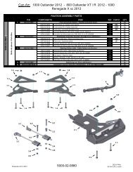
FIXATION ASSEMBLY PARTS<br />
P/N COMPONENTS ITEM REF PUNCH QTY<br />
1- 1004-20-0625 Front anti-pivot bracket / Fixation anti-pivot avant<br />
1x<br />
1004-20-0625-P-L1 Anti-rotation front bracket - LH / Ancrage anti-rotation avant - GA 1.1 EFL 1x<br />
1004-20-0625-P-R1 Anti-rotation front bracket - RH / Ancrage anti-rotation avant - DR 1.2 EFR 1x<br />
1033-08-0045 Hex bolt / Boulon hex, M8-1.25x45mm, GR8.8, ZP, DIN931 1.3 12x<br />
1045-10-7565 U-bolt / Boulon en U, M10-1.5x75x65mm, GR4.8, ZP 1.4 2x<br />
1060-10-0001 Washer / Rondelle plate, 20X10.5X2, ZP, DIN125A 1.5 4x<br />
1074-08-0001 Hex nylon nut / Écrou nylon hex, M8-1.25, GR8, ZP, DIN6926 1.6 12x<br />
1074-10-0001 Hex nylon nut / Écrou nylon hex, M10-1.5, GR8, ZP, DIN6926 1.7 4x<br />
4002-20-0626-P1 Reinforcement plate / Plaque de renfort 1.8 ES 2x<br />
2- 1005-20-0620 Rear anti-pivot bracket / Fixation anti-pivot arrière<br />
1x<br />
1005-20-0620-ASS Rear anti-pivot bracket / Fixation anti-pivot arrière 2.1 J1R 2x<br />
1006-05-5070-C Rear anti-pivot bracket cover / Couvert fixation anti-pivot arrière 2.2 C7 2x<br />
1033-12-B170 Hex bolt / Boulon hex, HCS Custom, M12-1.75 x 170, GR 8.8, ZP, DIN931 2.3 2x<br />
1071-12-0001 Hex nylon nut / Écrou nylon hex, M12-1.75, ZP, DIN982 2.4 2x<br />
1033-10-0045 Hex bolt / Boulon hex, M10-1.5x45mm, GR8.8, ZP, DIN931 2.5 2x<br />
1071-10-0001 Hex nylon nut / Écrou nylon hex, M10-1.5, GR8, ZP, DIN982 2.6 2x<br />
3- 1034-08-0716 <strong>Installation</strong> Stud / Goujon <strong>d'installation</strong> 7/16-20 x 1<br />
2x<br />
4- 1442-D2-X032 Bolt / Boulon HWB, 7/16-20 X 32, 5, 3/4 KEY<br />
20x<br />
5- 5000-20-0625-U4MAN <strong>Installation</strong> manual / <strong>Directives</strong> <strong>d'installation</strong> - <strong>Camoplast</strong> UTV 4S 5000-20-0625<br />
1x<br />
1.3<br />
1.3<br />
1.8<br />
1.3<br />
1.3<br />
1.8<br />
1.3<br />
1.3<br />
1.4<br />
1.4<br />
1.6<br />
1.6<br />
1.5<br />
1.7<br />
1.5<br />
1.7<br />
1.6<br />
1.6<br />
1.5<br />
1.7<br />
1.7<br />
1.5<br />
1.1<br />
1.2<br />
1.6<br />
1.6<br />
2.5<br />
2.5<br />
3<br />
2.2<br />
2.2<br />
2.3<br />
2.4<br />
2.3<br />
4<br />
2.1<br />
2.6<br />
2.4<br />
2.6<br />
2.1<br />
Production 2012-2013 5000-20-0625<br />
JD11-FM02<br />
07 décembre 2012, rev03
Page 3<br />
<strong>Installation</strong> <strong>Guidelines</strong> / <strong>Directives</strong> d’installation<br />
WARNING : Never place parts of your body under<br />
the vehicle unless it is securely installed on<br />
appropriate stands. Severe injuries could occur if<br />
the vehicle collapses or moves. Do not use a<br />
lifting device as a secure stand.<br />
PREPARATION / PRÉPARATION<br />
AVERTISSEMENT : Toujours s’assurer d’utiliser<br />
des supports sécuritaires avant de mettre des<br />
parties du corps sous le véhicule. Des blessures<br />
graves peuvent survenir si le véhicule tombe ou<br />
bouge. Ne pas utiliser un dispositif de levage<br />
comme support.<br />
1. Position the vehicle on a flat and level surface (or on<br />
a suitable lifting device), shift the transmission to<br />
neutral and turn off engine.<br />
2. Identify and position each unit of the track system<br />
near the position indicated on the sticker. Refer to<br />
Figure 1.<br />
1. Placer le véhicule sur une surface plane et au<br />
niveau (ou sur un dispositif de levage), mettre la<br />
transmission au point mort et arrêter le moteur.<br />
2. Identifier et placer chaque unité de l’ensemble de<br />
traction près de la position d’installation indiquée<br />
sur l’étiquette. Voir la Figure 1.<br />
Figure 1<br />
©2012 <strong>Camoplast</strong> Inc.
Page 4<br />
<strong>Installation</strong> <strong>Guidelines</strong> / <strong>Directives</strong> d’installation<br />
REAR TRACK SYSTEMS / SYSTÈMES DE TRACTION ARRIÈRE<br />
3. To install the REAR track systems on the UTV,<br />
proceed as follows:<br />
a. Using a lifting device, raise the rear of the UTV<br />
and install appropriate stands. Ensure that the<br />
vehicle is immobilized and safe to work on.<br />
b. Remove rear wheels. Clean wheel hubs. Refer<br />
to Figure 2.<br />
3. Pour installer les systèmes de traction ARRIÈRE du<br />
UTV, procéder comme suit:<br />
a. Au moyen d’un dispositif de levage, soulever<br />
l’arrière du UTV et installer des cales de sûreté.<br />
Assurez-vous que le véhicule est bien immobile<br />
et qu’on peut y travailler en toute sécurité<br />
b. Enlever les roues arrière. Nettoyer les moyeux<br />
de roue. Voir la Figure 2.<br />
Figure 2<br />
c. If applicable, remove CV joint protectors. Refer<br />
to Figure 3.<br />
c. Enlever les protecteurs de joint homocinétique,<br />
s’il y a lieu. Voir la Figure 3.<br />
Figure 3<br />
©2012 <strong>Camoplast</strong> Inc.
Page 5<br />
<strong>Installation</strong> <strong>Guidelines</strong> / <strong>Directives</strong> d’installation<br />
d. Remove the bolt, washers and spacer bushings<br />
from the rear stabilizing rod end and insert the<br />
bolt in the anchor bracket. Refer to Figure 4.<br />
NOTE: It is not possible to insert this bolt once the<br />
bracket is attached to the suspension arm.<br />
d. Enlever les boulons, les rondelles et les<br />
espaceurs des rotules des bras stabilisateurs<br />
arrière. Insérer un boulon à l’extrémité de<br />
chacun des ancrages de suspension. Voir la<br />
Figure 4.<br />
NOTA: Il est impossible d’insérer ce boulon après<br />
avoir fixé l’ancrage au bras de suspension.<br />
Figure 4<br />
e. Remove the mounting bolt that secures the<br />
lower suspension arm to the wheel hub. Position<br />
the suspension anchor bracket (1) under the<br />
suspension arm. Insert the new M10x170mm (2)<br />
mounting bolt through the anchor bracket, the<br />
lower suspension arm and the wheel hub.<br />
Position the bracket cover over the lower<br />
suspension arm. Insert bolt (3) in the anchor<br />
bracket hole, up through the lower suspension<br />
a-arm and bracket cover. Before the final<br />
tightening of the bracket assembly, adjust<br />
the wheel camber angle. Refer to the Rear<br />
Wheel Camber Adjustment section of the<br />
John Deere Technical Manual for procedure<br />
and specifications. Install nuts on the bolts and<br />
tighten them with a torque of 50 N•m. Refer to<br />
Figure 5.<br />
NOTE: On 2010 and 2011 models, the bolt (2)<br />
must be greased as per John Deere<br />
specifications.<br />
NOTE: On 2012 models, the bolt does not have<br />
to be greased. Refer to part (2) in Figure<br />
5.<br />
e. Dévisser et retirer le boulon de fixation qui relie<br />
le bras inférieur de suspension au moyeu de<br />
roue. Placer l’ancrage de suspension (1) sous le<br />
bras de suspension et insérer le nouveau<br />
boulon M10x170mm (2) à travers l’ancrage de<br />
suspension et la fixation du moyeu de roue.<br />
Positionner le couvercle de l’ancrage sur le bras<br />
de suspension inférieur. Insérer le boulon (3)<br />
dans le trou de l’ancrage de suspension, à<br />
travers le bras de suspension inférieur et le trou<br />
du couvercle préalablement positionné. Avant<br />
de complètement serrer l’assemblage de<br />
l’ancrage, s’assurer que l’angle de<br />
carrossage de la roue est correctement<br />
ajusté. Consulter la section « Ajustement de<br />
l’angle de carrossage des roues arrière » du<br />
Manuel technique de John Deere pour la<br />
procédure et les spécifications. Installer les<br />
écrous sur les boulons et serrer à un couple de<br />
50 N•m. Voir la Figure 5.<br />
NOTA: Sur les modèles 2010 et 2011, le<br />
boulon (2) doit être graissé selon les<br />
spécifications de John Deere.<br />
NOTA: Sur les modèles 2012, aucune graisse<br />
ne doit être appliquée au boulon. Voir la<br />
pièce (2) sur la Figure 5.<br />
©2012 <strong>Camoplast</strong> Inc.
Page 6<br />
<strong>Installation</strong> <strong>Guidelines</strong> / <strong>Directives</strong> d’installation<br />
Figure 5<br />
f. Use the two studs supplied to correctly position<br />
the system on the wheel hub. Refer to Figure 6.<br />
f. Utiliser les deux goujons fournis afin de<br />
positionner le système correctement sur le<br />
moyeu de roue. Voir la Figure 6.<br />
Figure 6<br />
©2012 <strong>Camoplast</strong> Inc.
Page 7<br />
<strong>Installation</strong> <strong>Guidelines</strong> / <strong>Directives</strong> d’installation<br />
g. Secure the undercarriage to the rear hub by<br />
using the wheel bolts provided. To install the<br />
track system, set the two screw-in wheel studs<br />
provided in the kit at the 10 and 2 o’clock positions,<br />
slide the track on the studs, and bolt the<br />
undercarriage to the hub with three (3) wheel bolts.<br />
Remove the screw-in studs and install the last two<br />
(2) wheel bolts. Refer to Figures 6 and 7 .<br />
NOTE: Ensure that the cotter pin of the UTV drive<br />
axle nut does not interfere with the<br />
undercarriage hub. If it does, adjust the<br />
length of the cotter pin.<br />
NOTE: Use the torque that is specified by the UTV<br />
manufacturer for wheel bolts.<br />
g. Fixer le système de traction au moyeu de roue<br />
arrière du UTV. Utiliser les boulons de roue<br />
fournis dans l’ensemble d’installation. Pour<br />
installer le système de traction, placer les deux<br />
goujons amovibles fournis à 10 et 2 heures,<br />
glisser la chenille sur les goujons et visser trois<br />
(3) boulons de roue sur le moyeu. Retirer les<br />
goujons amovibles et visser les deux (2)<br />
derniers boulons. Voir les figures 6 et 7.<br />
NOTA: S’assurer que la goupille fendue de l’écrou<br />
de l’essieu du UTV n’interfère pas avec le<br />
coeur du moyeu du système de traction. Si<br />
tel est le cas, ajuster la longueur de la<br />
goupille fendue.<br />
NOTA: Serrer les boulons de roue au couple de<br />
serrage indiqué par le fabricant de UTV.<br />
Figure 7<br />
©2012 <strong>Camoplast</strong> Inc.
Page 8<br />
<strong>Installation</strong> <strong>Guidelines</strong> / <strong>Directives</strong> d’installation<br />
h. Attach the stabilizing rod (2) to the anchor<br />
bracket (1), using the long spacer bushing (3),<br />
the short spacer bushing (4), flat washer (5) and<br />
nut (6). Torque to 50 N•m. Refer to Figure 8.<br />
NOTE: Ensure that parts are assembled in the<br />
correct order.<br />
h. Fixer le bras stabilisateur (2) au boulon déjà<br />
installé sur l’ancrage de suspension (1) à l’aide<br />
de l’espaceur long (3), l’espaceur court (4), de la<br />
rondelle (5) et de l’écrou autobloquant (6).<br />
Serrer à 50 N•m. Voir la Figure 8.<br />
NOTA: S’assurer d’assembler les pièces dans<br />
l’ordre indiqué.<br />
Figure 8<br />
i. Inspect the rear track systems and ensure that<br />
all mounting bolts were correctly tightened<br />
during installation. Lower the UTV to the ground<br />
and install the front track systems on the UTV.<br />
i. Inspecter les systèmes de traction arrière et<br />
assurez-vous que vous avez bien serré tous les<br />
boulons lors de l’installation. Abaisser ensuite le<br />
UTV au sol et procéder à l’installation des<br />
systèmes de traction avant du UTV.<br />
©2012 <strong>Camoplast</strong> Inc.
Page 9<br />
<strong>Installation</strong> <strong>Guidelines</strong> / <strong>Directives</strong> d’installation<br />
FRONT TRACK SYSTEMS / SYSTÈMES DE TRACTION AVANT<br />
4. To install the FRONT track systems on the UTV,<br />
proceed as follows:<br />
a. Using a lifting device, raise the front of the UTV<br />
and install appropriate stands. Ensure that the<br />
vehicle is immobilized and safe to work on.<br />
b. Remove front wheels. Clean wheel hubs. Refer<br />
to Figure 9.<br />
4. Pour installer les systèmes de traction AVANT du<br />
UTV, procéder comme suit:<br />
a. Au moyen d’un dispositif de levage, soulever<br />
l’avant du UTV et installer des cales de sûreté.<br />
S’assurer que le véhicule est bien immobile et<br />
qu’on peut y travailler en toute sécurité.<br />
b. Enlever les roues avant. Nettoyer les moyeux de<br />
roue. Voir la Figure 9.<br />
Figure 9<br />
c. If applicable, remove CV joint protectors. Refer<br />
to Figure 10.<br />
c. Enlever les protecteurs de joint homocinétique,<br />
s’il y a lieu. Voir la Figure 10.<br />
Figure 10<br />
©2012 <strong>Camoplast</strong> Inc.
Page 10<br />
<strong>Installation</strong> <strong>Guidelines</strong> / <strong>Directives</strong> d’installation<br />
d. Remove the bolt, washers and bushings from<br />
the front stabilizing rod end and insert the bolt in<br />
the anchor bracket. Refer to Figure 11.<br />
NOTE: It is not possible to insert this bolt once the<br />
bracket is attached to the suspension arm.<br />
d. Enlever les boulons, les rondelles et les<br />
espaceurs des rotules des bras stabilisateurs<br />
avant et insérer un boulon à l'extrémité de<br />
chacun des ancrages de suspension. Voir la<br />
Figure 11.<br />
NOTA: Il est impossible d’insérer ce boulon après<br />
avoir fixé l’ancrage au bras de suspension.<br />
Figure 11<br />
e. Position the reinforcement plate (1) under the<br />
lower suspension arm. Secure the wide end of<br />
the plate near the chassis with two M8x45mm<br />
mounting bolts (2). Secure the narrow end near<br />
the wheel hub by using a U-bolt (3). Make sure<br />
to install flat washers (4) on the U-bolt before<br />
installing the nuts. Refer to Figure 12.<br />
NOTE: Do not tighten the reinforcement plate<br />
mounting bolts completely yet.<br />
e. Positionner la plaque de renfort (1) sous le bras<br />
de suspension inférieur. Fixer l'extrémité située<br />
près du châssis à l'aide de deux boulons<br />
M8x45mm (2). Fixer l'extrémité de la plaque<br />
située près du moyeu de roue à l'aide du boulon<br />
en U (3). Assurez-vous d’insérer des rondelles<br />
plates (4) sur le boulon en U avant d’installer les<br />
écrous. Référez-vous à la Figure 12.<br />
NOTA: Ne pas serrer complètement les boulons de<br />
fixation de la plaque renfort à cette étape.<br />
Figure 12<br />
©2012 <strong>Camoplast</strong> Inc.
Page 11<br />
<strong>Installation</strong> <strong>Guidelines</strong> / <strong>Directives</strong> d’installation<br />
f. Insert four M8x45mm bolts (2) through the holes<br />
in the lower suspension arm and reinforcement<br />
plate installed in the previous step. Position the<br />
suspension anchor bracket (1) under the<br />
reinforcement plate and bolt it into position.<br />
Tighten the bolts and nuts adequately. Refer to<br />
Figure 13.<br />
NOTE: The M8x45mm mounting bolts must be<br />
tightened to 25 N-m. U-bolt nuts must be<br />
tightened to 50 N-m.<br />
f. Insérer 4 boulons M8x45mm (2) dans les trous<br />
du bras de suspension inférieur et de la plaque<br />
de renfort préalablement installé. Positionner<br />
l'ancrage de suspension (1) au-dessous du<br />
renfort de suspension et le fixer en place. Serrer<br />
les boulons et écrous de fixation de la plaque<br />
renfort et de l'ancrage adéquatement. Référezvous<br />
à la Figure 13.<br />
NOTA: Les boulons M8x45mm utilisés pour la<br />
fixation de l'ancrage doivent être serrés<br />
à un couple de 25 N-m. Les écrous de<br />
fixation du boulon en U doivent être<br />
serrés à un couple de 50 N-m.<br />
Figure 13<br />
g. Using the wheel bolts provided in the kit, secure<br />
undercarriages to the front wheel hubs. The<br />
procedure and precautions are the same as for<br />
rear units. See Figures 6 and 7 for reference.<br />
g. Au moyen des boulons de roue fournis dans<br />
l’ensemble d’installation, boulonner chaque<br />
système de traction au moyeu de roue avant. La<br />
marche à suivre et les précautions sont les<br />
mêmes que pour les systèmes arrière. Voir les<br />
figures 6 et 7 à titre de référence.<br />
©2012 <strong>Camoplast</strong> Inc.
Page 12<br />
<strong>Installation</strong> <strong>Guidelines</strong> / <strong>Directives</strong> d’installation<br />
h. Attach the stabilizing rod (2) to the anchor<br />
bracket (1), using the two spacer bushings (3),<br />
flat washer (4) and nut (5). Torque to 50 N•m.<br />
Refer to Figure 14.<br />
NOTE: Ensure that parts are assembled in the<br />
correct order.<br />
h. Fixer le bras stabilisateur (2) au boulon déjà<br />
installé sur l’ancrage de suspension (1) à l’aide<br />
des deux espaceurs (3), de la rondelle (4) et de<br />
l’écrou autobloquant (5). Serrer à 50 N•m. Voir<br />
la Figure 14.<br />
NOTA: S’assurer d’assembler les pièces dans<br />
l’ordre indiqué.<br />
Figure 14<br />
©2012 <strong>Camoplast</strong> Inc.
Page 13<br />
<strong>Installation</strong> <strong>Guidelines</strong> / <strong>Directives</strong> d’installation<br />
COMPLETION / COMPLÉTER L’INSTALLATION<br />
5. Check for possible contact between the<br />
undercarriage and the lower fender. If there is<br />
contact, the fender should be modified (cut) to avoid<br />
damage to the UTV and premature wear on rubber<br />
track.<br />
NOTE: ON SOME VEHICLES, there may be<br />
interference between the front fender<br />
guards and the track systems. Removing<br />
the guards is recommended to avoid<br />
damage to the track systems or fenders of<br />
the vehicle.<br />
a. Remove the mounting bolt (1) that attach the<br />
fender guard to the front bumper. Remove the<br />
two mounting bolts (2) that secure the fender<br />
guard to the vehicle footrest. Remove the fender<br />
guard from the front fender. See Figure 15.<br />
5. Vérifier s’il y a un contact possible entre le système<br />
de traction et l’aile inférieure. S’il y a contact,<br />
modifier (découper) l’aile pour éviter les dommages<br />
au UTV et toute usure prématurée des chenilles.<br />
NOTA: SUR CERTAINS VÉHICULES, il peut se<br />
produire une interférence entre le garde<br />
protecteur d’aile avant et la chenille. Il est<br />
recommandé de retirer ce protecteur afin<br />
de ne pas endommager le système de<br />
chenille ou l'aile du véhicule.<br />
a. Dévisser le boulon de fixation (1) qui maintient<br />
le garde protecteur au pare-chocs avant.<br />
Dévisser ensuite les deux boulons de fixation (2)<br />
du protecteur au marche-pied du véhicule.<br />
Retirer ensuite le garde protecteur d'aile avant.<br />
Voir la Figure 15.<br />
Figure 15<br />
©2012 <strong>Camoplast</strong> Inc.
Page 14<br />
<strong>Installation</strong> <strong>Guidelines</strong> / <strong>Directives</strong> d’installation<br />
6. To prevent any possible contact between the<br />
undercarriage and the front mud guard, shorten the<br />
mud guard by about 80 mm (1) and cut flush with<br />
the end of the fender guard. This will avoid damage<br />
to the UTV and premature wear on the rubber track.<br />
Refer to Figure 16.<br />
6. Pour éviter tout contact possible entre le système<br />
de traction et le garde-boue avant, raccourcir le<br />
garde-boue d’environ 80 mm (1) et couper à la<br />
hauteur du bout du protecteur d’aile. Ceci permettra<br />
d’éviter des dommages au UTV et l’usure<br />
prématurée des chenilles. Voir la Figure 16.<br />
Figure 16<br />
WARNING : The track systems may interfere with<br />
the rear bumper. The bumper should be modified<br />
or removed.<br />
WARNING : The rear track systems will interfere<br />
with the cargo box if raised.<br />
WARNING : The rear track systems will interfere<br />
with the tailgate if opened.<br />
AVERTISSEMENT : Les systèmes de chenille<br />
risquent d’entrer en contact avec le pare-chocs<br />
arrière. Le pare-chocs doit être modifié ou<br />
enlevé.<br />
AVERTISSEMENT : Les systèmes de chenilles<br />
entrent en contact avec la boîte de chargement si<br />
celle-ci est en position levée.<br />
AVERTISSEMENT : Les systèmes de chenilles<br />
entrent en contact avec le panneau de la boîte de<br />
chargement si celui-ci est ouvert.<br />
7. Lower the UTV to the ground. 7. Abaisser l’UTV au sol.<br />
ADJUSTMENTS / AJUSTEMENTS<br />
8. Adjust the alignment, angle of attack and rubber<br />
track tension as described in the User Manual.<br />
WARNING : Before first using your UTV equipped<br />
with track systems, the required pre-use<br />
adjustments must be made. For more information<br />
on these adjustments, see the USER MANUAL<br />
provided in the installation kit.<br />
8. Ajuster l’alignement, l’angle d’attaque et la tension<br />
de la chenille de la façon décrite dans le Manuel de<br />
l’utilisateur.<br />
AVERTISSEMENT : Avant l’utilisation de votre<br />
UTV équipé de systèmes de chenille, il est<br />
obligatoire d’effectuer les ajustements de<br />
pré–utilisation requis. Pour plus de<br />
renseignements sur ces ajustements, voir le<br />
MANUEL DE L’UTILISATEUR fourni avec<br />
l’ensemble d’installation.<br />
©2012 <strong>Camoplast</strong> Inc.
Page 15<br />
TECHNICAL SUPPORT / SOUTIEN TECHNIQUE<br />
Consult your dealer or distributor to solve any problem related with track system installation.<br />
Consultez votre concessionnaire ou votre distributeur afin de résoudre tout problème entourant<br />
l’installation des systèmes.<br />
Dealer or distributor phone :<br />
Tél. du concessionnaire ou du distributeur :<br />
Serial No. / No de série :<br />
Purchase date / Date d’achat :<br />
©2012 <strong>Camoplast</strong> Inc.