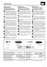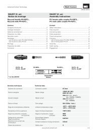
Assembly instructions MA231 (fr_en) - Multi-Contact
Assembly instructions MA231 (fr_en) - Multi-Contact
Assembly instructions MA231 (fr_en) - Multi-Contact

Create successful ePaper yourself
Turn your PDF publications into a flip-book with our unique Google optimized e-Paper software.
Advanced <strong>Contact</strong> Technology<br />
MA000 <strong>MA231</strong> (de_<strong>en</strong>) (<strong>fr</strong>_<strong>en</strong>)<br />
Montageanleitung<br />
Notice de montage<br />
Raccord mâle PV-KST4/...-UR*<br />
Raccord femelle PV-KBT4/...-UR*<br />
Cont<strong>en</strong>u<br />
Consignes de sécurité ................................................................2<br />
Outillage nécessaire ..................................................................3<br />
Préparation du câble ..................................................................4<br />
Sertissage ..................................................................................4<br />
Test d‘assemblage .....................................................................5<br />
Embrochage / Débrochage<br />
– sans clip de sécurité PV-SSH4 ...............................................6<br />
– avec clip de sécurité PV-SSH4 ...............................................6<br />
Disposition du câble ..................................................................7<br />
* UL fi le E343181<br />
Raccord femelle / Female cable coupler<br />
PV-KBT4/...<br />
En option / Optional<br />
PV-SSH4<br />
Clip de sécurité / Safety lock clip<br />
MA000 <strong>MA231</strong> (de_<strong>en</strong>) (<strong>fr</strong>_<strong>en</strong>)<br />
<strong>Assembly</strong> <strong>instructions</strong><br />
(voir / see www.multi-contact.com --> MA252)<br />
PV male cable coupler PV-KST4/...-UR*<br />
PV female cable coupler PV-KBT4/...-UR*<br />
Cont<strong>en</strong>t<br />
Safety Instructions ......................................................................2<br />
Tools required ............................................................................3<br />
Cable preparation ......................................................................4<br />
Crimping ....................................................................................4<br />
<strong>Assembly</strong> check ........................................................................5<br />
Plugging and unplugging the cable coupler<br />
– without safety lock clip PV-SSH4 ...........................................6<br />
– with safety lock clip PV-SSH4 ................................................6<br />
Cable routing .............................................................................7<br />
Raccord mâle / Male cable coupler<br />
PV-KST4/...<br />
Données techniques Technical data<br />
Système de connexion Connector system Ø 4mm<br />
T<strong>en</strong>sion assignée Rated voltage<br />
1000V DC (IEC)<br />
600V DC (UL)<br />
17A (1,5mm²)<br />
Courant assigné IEC (90°C) Rated curr<strong>en</strong>t IEC (90°C)<br />
22,5A (2,5mm², 14AWG)<br />
30A (4mm², 6mm², 10AWG)<br />
43A (10mm²)<br />
Courant assigné IEC (85°C) Rated curr<strong>en</strong>t IEC (85°C)<br />
39A (4mm²)<br />
45A (6mm²)<br />
T<strong>en</strong>sion d'essai Test voltage 6kV (50Hz, 1min.)<br />
-40°C...+90°C (IEC)<br />
Plage de la température ambiante Ambi<strong>en</strong>t temperature range<br />
-40°C...+75°C (UL)<br />
-40°C...+70°C (UL: 14AWG)<br />
Température limite supérieure Upper limiting temperature 105°C (IEC)<br />
Degré de protection, branché<br />
Degree of protection, mated<br />
IP68 (1m/1h)<br />
non branché<br />
unmated<br />
IP2X<br />
Catégorie de surt<strong>en</strong>sion / degré de pollution Overvoltage category / Pollution degree CATIII / 2<br />
Résistance de contact des connecteurs <strong>Contact</strong> resistance of plug connectors 0,5mΩ<br />
Classe de protection Safety class II<br />
www.multi-contact.com 1 / 8
Advanced <strong>Contact</strong> Technology<br />
Consignes de sécurité Safety Instructions<br />
Le montage et l’installation des produits ne doiv<strong>en</strong>t être effectués<br />
que par du personnel qualifi é et formé <strong>en</strong> respectant<br />
toutes les dispositions de sécurité et réglem<strong>en</strong>tations légales<br />
applicables.<br />
<strong>Multi</strong>-<strong>Contact</strong> (MC) décline toute responsabilité <strong>en</strong> cas de<br />
non-respect de ces consignes.<br />
Utiliser uniquem<strong>en</strong>t les pièces et outils recommandés par MC.<br />
Suivre scrupuleusem<strong>en</strong>t les étapes de préparation et de montage<br />
décrites ici, faute de quoi ni la sécurité ni le respect des<br />
caractéristiques techniques ne sont garantis. Ne pas modifi er<br />
le produit d’une quelconque manière.<br />
Les connecteurs non fabriqués par MC qui sont <strong>en</strong>fi chables<br />
avec des élém<strong>en</strong>ts MC, et parfois qualifi és de «compatibles<br />
MC» par les fabricants, ne répond<strong>en</strong>t pas aux exig<strong>en</strong>ces d’une<br />
liaison électrique sûre et stable à long terme. Ils ne doiv<strong>en</strong>t<br />
pas, pour des raisons de sécurité, être <strong>en</strong>fi chés dans des élém<strong>en</strong>ts<br />
MC. Nous déclinons par conséqu<strong>en</strong>t toute responsabilité<br />
si ces connecteurs non approuvés par MC sont utilisés<br />
avec des élém<strong>en</strong>ts MC et qu’il <strong>en</strong> résulte des dommages.<br />
Les travaux décrits ici ne doiv<strong>en</strong>t pas être effectués<br />
sur des parties parcourues par un courant ou sous<br />
t<strong>en</strong>sion.<br />
La protection contre les chocs électriques doit être<br />
assurée par le produit fi nal et garantie par l’utilisateur.<br />
Les connecteurs ne doiv<strong>en</strong>t pas être débranchés<br />
sous charge. L’embrochage et le débrochage sous<br />
t<strong>en</strong>sion sont permis.<br />
Les connecteurs sont étanches à l’eau selon le degré<br />
de protection IP. Ils ne sont cep<strong>en</strong>dant pas conçus<br />
pour une utilisation perman<strong>en</strong>te sous l’eau. Ne pas<br />
poser les connecteurs directem<strong>en</strong>t sur le toit.<br />
Les connecteurs non branchés doiv<strong>en</strong>t être protégés<br />
contre l’humidité et la saleté par un bouchon de<br />
fermeture (MC4 N° d’article 32.0716 pour douilles et<br />
32.0717 pour fi ches). Il est interdit d’embrocher des<br />
connecteurs <strong>en</strong>crassés.<br />
La connexion ne doit jamais être soumise à un effort<br />
de traction mécanique perman<strong>en</strong>t. Le câble doit être<br />
fi xé au moy<strong>en</strong> de colliers.<br />
Pour des raisons de sécurité, MC interdit l‘utilisation<br />
de câbles PVC ou de câbles non étamés du type<br />
HO7RN-F.<br />
Pour des caractéristiques techniques détaillées, se<br />
reporter au catalogue des produits.<br />
2 / 8 www.multi-contact.com<br />
The products may be assembled and installed only by suitably<br />
qualifi ed and trained specialists with due observance of<br />
all applicable safety regulations.<br />
<strong>Multi</strong>-<strong>Contact</strong> (MC) declines any liability in the ev<strong>en</strong>t of failure<br />
to observe these warnings.<br />
Use only the compon<strong>en</strong>ts and tools specifi ed by MC. Do not<br />
deviate <strong>fr</strong>om the preparation and assembly procedures described<br />
here, since in this ev<strong>en</strong>t, in the ev<strong>en</strong>t of self-assembly,<br />
no guarantee can be giv<strong>en</strong> as to safety or conformity with the<br />
technical data. Do not modify the product in any way.<br />
Connectors not made by MC which can be mated with MC<br />
elem<strong>en</strong>ts and in some cases are also described as ”MC-compatible”<br />
do not conform to the requirem<strong>en</strong>ts for safe electrical<br />
connection with long-term stability, and for safety reasons<br />
must not be plugged together with MC elem<strong>en</strong>ts. MC can<br />
therefore accept no liability for damage which occurs as a result<br />
of mating these connectors which lack MC approval with<br />
MC elem<strong>en</strong>ts.<br />
The work described here must not be carried out<br />
on live or load-carrying parts.<br />
Protection <strong>fr</strong>om electric shock must be assured by<br />
the <strong>en</strong>d product and its user.<br />
The plug connections must not be disconnected<br />
under load. Plugging and unplugging wh<strong>en</strong> live is<br />
permitted.<br />
The plug connectors are watertight in accordance<br />
with IP protection class. However, they are not suitable<br />
for continuous operation under water. Do not<br />
place the plug connectors directly on the roof membrane.<br />
Unmated plug connectors must be protected <strong>fr</strong>om<br />
moisture and dirt with a sealing cap (MC4 Article<br />
No. 32.0716 for sockets and 32.0717 for plugs). The<br />
male and female parts must not be plugged together<br />
wh<strong>en</strong> soiled.<br />
The plug connection must not be subjected to<br />
continuous mechanical t<strong>en</strong>sion. The cable should be<br />
fi xed with cable binders.<br />
For safety reasons MC prohibits the use of either<br />
PVC cables or untinned cables of type H07RN-F.<br />
For further technical data please see the product<br />
catalogue.<br />
Explication des symboles Explanation of the symbols<br />
Mise <strong>en</strong> garde contre une t<strong>en</strong>sion électrique dangereuse<br />
Warning of dangerous voltages<br />
Mise <strong>en</strong> garde contre un danger Warning of a hazard area<br />
Remarque ou conseil utile Useful hint or tip
Advanced <strong>Contact</strong> Technology<br />
CHROM - VANADIUM<br />
1<br />
2<br />
3<br />
4<br />
5<br />
6<br />
7<br />
8<br />
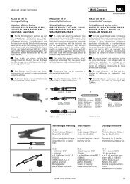
Outillage nécessaire Tools required<br />
(ill. 1)<br />
Pince à dénuder PV-AZM... avec<br />
couteaux intégrés ainsi qu‘une clé à<br />
6 pans 2,5mm.<br />
Section du câble: 1,5 / 2,5 / 4 / 6mm²<br />
Type: PV-AZM-1.5/6<br />
No. de Cde.: 32.6029-156<br />
Section du câble: 4 / 6 / 10mm²<br />
Type: PV-AZM-4/10<br />
No. de Cde.: 32.6027-410<br />
(ill. 2)<br />
Pince à sertir PV-CZM... avec positionneur<br />
et matrice de sertissage<br />
intégrée.<br />
Section du câble:<br />
1,5 / 2,5 / 4mm² (14 / 12AWG)<br />
Type: PV-CZM-18100<br />
No. de Cde.: 32.6020-18100<br />
Section du câble:<br />
2,5 / 4 / 6mm² (12 / 10AWG)<br />
Type: PV-CZM-19100<br />
No. de Cde.: 32.6020-19100<br />
Section du câble: 4 / 10mm²<br />
(12AWG)<br />
Type: PV-CZM-20100<br />
No. de Cde.: 32.6020-20100<br />
(ill. 3)<br />
Clé à fourche PV-MS,<br />
1 Set = 2 pièces<br />
No. de Cde.: 32.6024<br />
(ill. 4)<br />
Clé de serrage PV-WZ-AD/GWD<br />
No. de Cde.: 32.6006<br />
(ill. 5)<br />
Clé pour contrer PV-SSE-AD4<br />
No. de Cde.: 32.6026<br />
(ill. 6)<br />
Fiche de test PV-PST<br />
No. de Cde.: 32.6028<br />
(ill. 7)<br />
Clé à fourche 15mm<br />
(ill. 8)<br />
Clé dynamométrique 12mm<br />
(ill. 1)<br />
Stripping pliers PV-AZM... incl.<br />
built-in blade as well as hexagonal<br />
screwdriver A/F 2,5mm.<br />
Cable cross section: 1,5 / 2,5 / 4 / 6mm²<br />
Type: PV-AZM-1.5/6<br />
Order No. 32.6029-156<br />
Cable cross section: 4 / 6 / 10mm²<br />
Type: PV-AZM-4/10<br />
Order No. 32.6027-410<br />
(ill. 2)<br />
Crimping pliers PV-CZM... incl. Locator<br />
and built-in crimping insert.<br />
Crimping range:<br />
1,5 / 2,5 / 4mm² (14 / 12AWG)<br />
Type: PV-CZM-18100<br />
Order No. 32.6020-18100<br />
Crimping range:<br />
2,5 / 4 / 6mm² (12 / 10AWG)<br />
Type: PV-CZM-19100<br />
Order No. 32.6020-19100<br />
Crimping range: 4 / 10mm² (12AWG)<br />
Type: PV-CZM-20100<br />
Order No. 32.6020-20100<br />
(ill. 3)<br />
Op<strong>en</strong>-<strong>en</strong>d spanner PV-MS,<br />
1 Set = 2 pieces<br />
Order No. 32.6024<br />
(ill. 4)<br />
PV-WZ-AD/GWD socket wr<strong>en</strong>ch<br />
insert to tight<strong>en</strong><br />
Order No. 32.6006<br />
(ill. 5)<br />
PV-SSE-AD4 socket wr<strong>en</strong>ch insert<br />
to secure<br />
Order No. 32.6026<br />
(ill. 6)<br />
Test plug PV-PST<br />
Order No. 32.6028<br />
(ill. 7)<br />
Op<strong>en</strong>-<strong>en</strong>d spanner A/F 15mm<br />
(ill. 8)<br />
Torque screwdriver A/F 12mm<br />
www.multi-contact.com 3 / 8
Advanced <strong>Contact</strong> Technology<br />
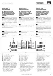
Tab. 1<br />
6 - 7,5mm<br />
A<br />
A<br />
b: Largeur de contrôle<br />
b: Control dim<strong>en</strong>sion<br />
4 / 8 www.multi-contact.com<br />
b<br />
b<br />
9<br />
Section du câble<br />
Conductor cross section<br />
10<br />
11<br />
Préparation du câble Cable preparation<br />
Des câbles de raccordem<strong>en</strong>t de classe<br />
de souplesse 5 et 6 peuv<strong>en</strong>t être<br />
raccordés.<br />
Remarque:<br />
Ne pas utiliser des conducteurs<br />
nus ou déjà oxydés. Les conducteurs<br />
étamés sont avantageux.<br />
Tous les câbles solaires de MC<br />
sont fabriqués avec des conducteurs<br />
étamés de grande qualité.<br />
(ill. 9, Tab. 1)<br />
Verifi er les dim<strong>en</strong>sions A et B selon<br />
illustration 9 et tableau 1.<br />
Cables with a strand construction of<br />
classes 5 and 6 can be connected.<br />
Att<strong>en</strong>tion:<br />
Use no uncoated or already<br />
oxidised conductors. It is recomm<strong>en</strong>ded<br />
to use tinned conductors.<br />
All MC solar cables have<br />
high-quality, tinned conductors.<br />
(ill. 9, Tab. 1)<br />
Check dim<strong>en</strong>sions A and b in accordance<br />
with illustration 9 and table 1.<br />
A: Ø sur isolant/câble mm<br />
A: Ø range of cable mm<br />
3 – 6 5,5 – 9<br />
mm mm² AWG Type<br />
~ 3 1,5 – 2,5 14 PV-K...T4/...2,5l PV-K...T4/...2,5II<br />
~ 5 4 – 6 12 / 10 PV-K...T4/...6I PV-K...T4/...6II<br />
~ 7,2 10 – – PV-K...T4/...10II<br />
(ill. 10)<br />
Dénuder le câble.<br />
Enlevez l‘isolation du câble sur une<br />
longueur de 6mm à 7,5mm.<br />
Att<strong>en</strong>tion<br />
Veillez à ne pas couper de brins<br />
<strong>en</strong> dénudant le câble!<br />
Remarque:<br />
Pour l’utilisation de la pince à<br />
dénuder PV-AZM... ainsi que sur le<br />
remplacem<strong>en</strong>t de jeux de couteaux,<br />
reportez-vous à la notice d’utilisation<br />
MA267 sur www.multi-contact.com<br />
Sertissage Crimping<br />
(ill. 11)<br />
Ouvrir l’étrier (K) et le maint<strong>en</strong>ir.<br />
Insérer le contact dans la zone de section<br />
appropriée de la pince à sertir.<br />
Tourner les languettes de sertissage<br />
vers le haut. Relacher l’étrier (K). Le<br />
contact est fi xé.<br />
(ill. 10)<br />
Strip cable insulation.<br />
Remove 6mm to 7,5mm of insulation<br />
<strong>fr</strong>om the <strong>en</strong>d of the cable.<br />
Att<strong>en</strong>tion:<br />
Do not cut individual strands at<br />
stripping<br />
Note:<br />
For directions on the operation of<br />
stripping pliers PV-AZM... and changing<br />
blade sets, see operating instruction<br />
MA267 at<br />
www.multi-contact.com<br />
(ill. 11)<br />
Op<strong>en</strong> the clamp (K) and hold. Place<br />
the contact in the appropriate crosssection<br />
range.<br />
Turn the crimp lugs upwards. Release<br />
the clamp (K). The contact is fi xed.
Advanced <strong>Contact</strong> Technology<br />
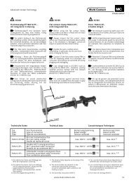
12<br />
13<br />
14<br />
15<br />
16<br />
(ill. 12)<br />
Serrer légèrem<strong>en</strong>t la pince pour que<br />
les pattes de sertissage se trouv<strong>en</strong>t<br />
à coup sûr dans la matrice de sertissage.<br />
(ill. 13)<br />
Introduire le câble dénudé jusqu’à ce<br />
que l’isolant bute sur la matrice de<br />
sertissage. Fermer complètem<strong>en</strong>t la<br />
pince à sertir.<br />
(ill. 14)<br />
Contrôlez le sertissage visuellem<strong>en</strong>t.<br />
Remarque:<br />
Pour l’utilisation des pinces à sertir,<br />
voir MA251 sur<br />
www.multi-contact.com<br />
(ill. 12)<br />
Press the pliers g<strong>en</strong>tly together until<br />
the crimp lugs are properly located<br />
within the crimping die.<br />
(ill. 13)<br />
Insert the stripped cable <strong>en</strong>d until the<br />
insulation comes up against the crimp<br />
insert. Completely close the crimping<br />
pliers.<br />
(ill. 14)<br />
Visually check the crimp.<br />
Note:<br />
For directions on the operation of<br />
the crimping tool, please see operating<br />
<strong>instructions</strong> MA251 at<br />
www.multi-contact.com<br />
Contrôle de l‘assemblage <strong>Assembly</strong> check<br />
(ill. 15)<br />
Introduisez le contact serti par l’arrière<br />
dans l’isolation de fi che ou de douille<br />
jusqu’à l’<strong>en</strong>cl<strong>en</strong>chem<strong>en</strong>t. Exercez<br />
une légère traction sur le câble pour<br />
contrôler que la pièce métallique est<br />
bi<strong>en</strong> <strong>en</strong>cl<strong>en</strong>chée.<br />
(ill. 16)<br />
Enfi chez la fi che de test par le côté<br />
correspondant dans la douille ou la<br />
fi che jusqu’<strong>en</strong> butée. Si le contact est<br />
monté correctem<strong>en</strong>t, le marquage<br />
blanc sur la fi che de test est <strong>en</strong>core<br />
visible.<br />
(ill. 15)<br />
Insert the crimped-on contact into the<br />
insulator of the male or female coupler<br />
until it clicks into place. Pull g<strong>en</strong>tly on<br />
the lead to check that the metal part is<br />
correctly <strong>en</strong>gaged.<br />
(ill. 16)<br />
Insert the appropriate <strong>en</strong>d of the test<br />
pin into the male or female coupler as<br />
far as it will go. If the contact is correctly<br />
located, the white mark on the<br />
test pin must still be visible.<br />
www.multi-contact.com 5 / 8
Advanced <strong>Contact</strong> Technology<br />
avec PV-MS<br />
with PV-MS<br />
à la main<br />
by hand<br />
6 / 8 www.multi-contact.com<br />
17<br />
18<br />
19<br />
20<br />
(ill. 17)<br />
Serrer manuellem<strong>en</strong>t le presse-étoupe<br />
à l‘aide des clés PV-MS<br />
et<br />
Serrer le presse-étoupe à l‘aide des<br />
outils PV-WZ-AD/GWD et<br />
PV-SSE-AD4.<br />
En tous les cas:<br />
Le couple de serrage doit être adapté<br />
aux câbles solaires utilisés. Les valeurs<br />
typiques sont de l‘ordre de<br />
2,5Nm à 3Nm.<br />
Embrochage / Débrochage<br />
sans clip de sécurité PV-SSH4<br />
Embrochage<br />
(ill. 18)<br />
Embrocher le connecteur jusqu‘au<br />
verrouillage. Contrôler le verrouillage<br />
<strong>en</strong> tirant sur le connecteur.<br />
Débrochage<br />
(ill. 19)<br />
Pour déconnecter les contacts, comprimez<br />
les languettes de verrouillage<br />
(X) soit à la main, soit avec l‘outil<br />
PV-MS, et séparez les deux moitiés du<br />
connecteur.<br />
Embrochage / Débrochage<br />
avec clip de sécurité PV-SSH4<br />
Embrochage<br />
(ill. 20)<br />
Embrochez le connecteur jusqu‘au<br />
verrouillage. Contrôlez le verrouillage<br />
<strong>en</strong> tirant sur le connecteur.<br />
Débrochage<br />
Le connecteur peut être déconnecté<br />
uniquem<strong>en</strong>t avec l‘outil PV-MS. Comprimez<br />
les languettes de verrouillage<br />
(X) avec l‘outil PV-MS et séparez les<br />
deux moitiés du connecteur.<br />
(ill. 17)<br />
Screw up the cable gland hand-tight<br />
with the tools PV-MS<br />
or<br />
tight<strong>en</strong> the cable gland with the tools<br />
PV-WZ-AD/GWD and PV-SSE-AD4.<br />
In both cases:<br />
The tight<strong>en</strong>ing torque must be appropriate<br />
for the solar cables used.<br />
Typical values are betwe<strong>en</strong> 2,5Nm and<br />
3Nm.<br />
Plugging and unplugging the<br />
cable coupler without safety<br />
lock clip PV-SSH4<br />
Plugging<br />
(ill. 18)<br />
Plug the parts of the cable coupler together<br />
until they click in place. Check<br />
that they have <strong>en</strong>gaged properly by<br />
pulling on the cable coupler.<br />
Unplugging<br />
(ill. 19)<br />
To disconnect the contacts, press the<br />
latches (X) together either by hand<br />
or with the tool PV-MS and pull the<br />
halves of the cable coupler apaart.<br />
Plugging and unplugging the<br />
cable coupler with safety<br />
lock clip PV-SSH4<br />
Plugging<br />
(ill. 20)<br />
Plug the parts of the cable coupler together<br />
until they click in place. Check<br />
that they have <strong>en</strong>gaged properly by<br />
pulling on the cable coupler.<br />
Unplugging<br />
The cable coupler can be disconnected<br />
only with the tool PV-MS.<br />
Press the latches (X) together with the<br />
tool PV-MS and pull the halves of the<br />
coupler apart.
Advanced <strong>Contact</strong> Technology<br />
20mm 20mm<br />
Disposition du câble Cable routing<br />
Aucune déformation dans la zone du The forces must not create a visible<br />
joint de l’isolation doit être visible. deformation in the sealing portion of<br />
Se référer aux spécifi cations du the insulation.<br />
fabricant de câbles pour un rayon de Refer to cable manufacturers specifi -<br />
courbure minimal.<br />
cation for minimum b<strong>en</strong>ding radius.<br />
20mm 20mm<br />
www.multi-contact.com 7 / 8
Advanced <strong>Contact</strong> Technology<br />
Notes:<br />
alterations<br />
to Subject / réserve sous cations Modifi – Communications Global l, Index 06.2012, – <strong>MA231</strong> –<br />
Fabricant/Producer:<br />
Switzerland<br />
<strong>Multi</strong>-<strong>Contact</strong> AG<br />
AG,<br />
Stockbrunn<strong>en</strong>rain 8<br />
CH – 4123 Allschwil<br />
Tel. +41/61/306 55 55<br />
Fax +41/61/306 55 56<br />
<strong>Multi</strong>-<strong>Contact</strong><br />
mail basel@multi-contact.com<br />
by<br />
www.multi-contact.com ©