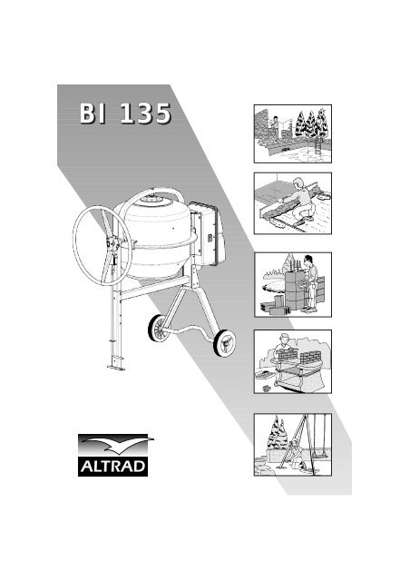
recambios hormigonera bi 135 - Altrad Benelux
recambios hormigonera bi 135 - Altrad Benelux
recambios hormigonera bi 135 - Altrad Benelux
You also want an ePaper? Increase the reach of your titles
YUMPU automatically turns print PDFs into web optimized ePapers that Google loves.
BI <strong>135</strong>
F<br />
D<br />
GB<br />
E<br />
2<br />
3<br />
7<br />
11<br />
15
UTILISATION - ENTRETIEN - PIÈCES DE RECHANGE<br />
BÉTONNIÈRE BI <strong>135</strong><br />
2<br />
F<br />
3<br />
1<br />
4<br />
5<br />
6<br />
7<br />
Béton de fondation<br />
(Béton de propreté, semelle)<br />
Béton armé courant<br />
(dalle de compression)<br />
Béton armé<br />
(linteau, poutre)<br />
Mortier (assemblage<br />
briques, parpaings)<br />
Mortier<br />
(enduit, chape)<br />
Mortier<br />
(scellement de carrelage)<br />
FABRICATION DES BÉTONS ET MORTIERS<br />
Le disque d’inclinaison possède 7 crans différents<br />
Position 1 Ouverture de la cuve vers le haut.<br />
Position 2 Malaxage à gauche.<br />
Position 3 Vidange côté gauche.<br />
Position 4 Ouverture de la cuve vers le bas.<br />
Position 5 Vidange côté droit.<br />
Position 6 et 7 Malaxage à droite.<br />
Dosage des bétons et mortiers courants<br />
pour 1 sac de ciment de 25 kg<br />
Sable<br />
0,2 à 0,5<br />
mm<br />
50 litres<br />
40 litres<br />
30 litres<br />
60 litres<br />
50 litres<br />
100 litres<br />
- Positionner la cuve à l’inclinaison choisie (d’un côté<br />
ou de l’autre). L’inclinaison la plus proche de<br />
l’horizontale donne un meilleur malaxage des<br />
matériaux collants (mortiers) mais réduit la capacité.<br />
- Introduire dans la cuve un peu d’eau, ajouter les<br />
agrégats (gravier ou sable) puis le ciment. Faire le<br />
complément d’eau en cours de chargement. Le<br />
tableau de dosage vous guidera dans vos<br />
travaux.La quantité d’eau est donnée à titre<br />
indicatif, elle dépend du degré d’humidité des<br />
agrégats.<br />
CARACTÉRISTIQUES TECHNIQUES BI <strong>135</strong><br />
Capacité de cuve L 130<br />
Capacité de malaxage maximum L 110<br />
Moteur monophasé 230V/50Hz<br />
Puissance maxi absorbée au démarrage W 600<br />
Longueur mm 1170<br />
Largeur mm 710<br />
Hauteur mm 1400<br />
Roues pleines ø mm 200<br />
Poids kg 54<br />
3<br />
Gravier<br />
20 mm<br />
80 litres<br />
60 litres<br />
50 litres<br />
-<br />
-<br />
-<br />
Eau<br />
13 litres<br />
environ<br />
13 litres<br />
environ<br />
15 litres<br />
environ<br />
13 litres<br />
environ<br />
12 à 15 litres<br />
environ<br />
13 litres<br />
environ<br />
- Laisser tourner la cuve une à deux minute environ,<br />
pour obtenir un bon mélange. Ne pas prolonger le<br />
malaxage au-delà de deux minutes, afin d’éviter de<br />
centrifuger les matériaux.<br />
- 1 pelletée = environ 4 litres , 1 brouette = environ<br />
60 litres.<br />
Les proportions ci-dessus sont données à titre<br />
indicatif et ne peuvent en aucun cas engager la<br />
responsa<strong>bi</strong>lité du fabricant.<br />
Test réalisé avec<br />
Lafarge Ciments
Référence Désignation Repères<br />
650349 Traverse de châssis 1 + visserie<br />
650350 Cuve complète sans roulement 29 + 31 + visserie<br />
650351 Jeux de palettes de cuve 30(2) + visserie<br />
650352 Pied avant 3 + visserie<br />
650353 Pied arrière 2 + 4(2) + 5(2) + visserie<br />
650354 Ensemble roulements de cuve 24 + 25 + 26(2) + 27(2) + 28 + visserie<br />
650355 Arbre d’entrainement complet 13(2) + 14 + 15 + 16(2) + 17 + 18(2) + 20 + 21 + 38 + 43 + 44<br />
650356 Protège pignon complet 19 + 9 + visserie<br />
650357 Montant support capot 6 + visserie<br />
650358 Couvercle moteur 40 + visserie<br />
650359 Capot moteur complet sans moteur 33 + 34 + 40 + visserie<br />
650360 Prise électrique 35<br />
650361 Interrupteur 36<br />
650362 Moteur mono 230V/50Hz 39<br />
650363 Etrier complet 8 + 12<br />
650364 Volant complet 10 + 11 + 32 + visserie<br />
650365 Pédale de blocage complète 7 + 22 + 23 + visserie<br />
401694 Courroie PJ711 larg. 18 mm 37<br />
401636 Roue caoutchouc ø 200 mm 4 + 5<br />
* Repère 41 et 42, uniquement pour le transport.<br />
4<br />
F
■ MISE EN SERVICE<br />
Placer la bétonnière sur un sol dur et <strong>bi</strong>en<br />
horizontal afin d’assurer à la machine une<br />
bonne sta<strong>bi</strong>lité. Dégager les abords de la<br />
machine de tout objet pouvant occasionner<br />
un risque accidentel ou gêner l’utilisateur.<br />
Avant de mettre votre bétonnière en<br />
marche, vérifier que :<br />
◆ Bétonnière à Moteur Electrique<br />
Monophasé<br />
• La tension du réseau est de 230 Volts.<br />
• Capacité minimum du compteur doit être de<br />
5 ampères.<br />
• L’ensemble capot moteur bénéficie de la<br />
double isolation classe II.<br />
• Prévoir un câble d’alimentation de deux<br />
conducteurs de section 2,5 mm 2 pour une<br />
longueur maximale de 50 m (matériel classe<br />
II : pas de fil de terre). Si la longueur est<br />
supérieure à 50 m, prévoir une section de fil<br />
plus forte.<br />
CONSIGNES DE SÉCURITÉ<br />
Générales<br />
Vérifier avant la mise en marche de votre<br />
bétonnière :<br />
• Que tous les dispositifs de protection sont<br />
en place et en bon état.<br />
• Que personne n’est en contact avec la<br />
bétonnière ou à proximité et qu’aucun outil<br />
n’est appuyé contre.<br />
• Ne jamais laisser un câble enroulé sur son<br />
support, cela provoque des chutes de<br />
tension importantes occasionnant une<br />
surchauffe du moteur.<br />
• La ligne doit être équipée de fusibles ou<br />
disjoncteur pour assurer la protection.<br />
ATTENTION : Eviter de faire tourner à vide<br />
une bétonnière équipée d’un moteur<br />
électrique monophasé; cela provoque une<br />
surchauffe du moteur.<br />
F<br />
5<br />
■ ENTRETIEN<br />
• Après chaque utilisation, nettoyer l’intérieur<br />
et l’extérieur de votre bétonnière. Pour la<br />
laver avec un jet ou un nettoyeur HP, veiller<br />
à ce que les projections d’eau n’atteignent<br />
pas le moteur. Pour nettoyer l’intérieur de la<br />
cuve efficacement, utiliser une pelletée de<br />
gravillons et de l’eau.<br />
• Ne pas oublier de temps en temps de huiler<br />
les paliers de rotation de l’étrier.<br />
• Les roulements de la cuve et du pignon<br />
d’entraînement sont graissés à vie.<br />
• Pression acoustique 74 dB(A) à 1 m.<br />
■ MAINTENANCE<br />
Le pignon d’entraînement de cuve est une<br />
pièce d’usure de votre bétonnière. Pour<br />
éviter toute immo<strong>bi</strong>lisation, il est prudent de<br />
prévoir une pièce d’avance.
CONSIGNES DE SÉCURITÉ<br />
• Ne pas mettre les mains, la tête ou<br />
quelconque outil à l’intérieur de la cuve<br />
lorsqu’elle est en mouvement.<br />
• Ne jamais faire fonctionner la bétonnière<br />
sans ses protections.<br />
• Ne pas brancher et utiliser le moteur<br />
électrique hors de son fonctionnement prévu<br />
capot fermé.<br />
• Arrêter et débrancher votre bétonnière avant<br />
toutes interventions de quelque nature que ce<br />
soit.<br />
• N’utiliser le mélangeur de la bétonnière<br />
qu’avec des matériaux destinés à la<br />
maçonnerie (Tout autre mélange d’ordre<br />
chimique ou alimentaire est déconseillé).<br />
• Ne jamais remplacer une pièce défectueuse<br />
par une pièce d’une marque différente.<br />
Débrancher le cordon d'alimentation<br />
secteur avant d'ouvrir le capot. L'appareil<br />
doit être utilisé uniquement lorsque toutes<br />
les protections sont en place.<br />
Attention : Appareil doublement isolé. Lors<br />
de réparations, la classe II n'est préservée<br />
qu'à condition d'utiliser les pièces d'origine<br />
et que les distances d'isolation ne soient<br />
pas modifiées.<br />
Le constructeur décline toute<br />
responsa<strong>bi</strong>lité en cas de non respect des<br />
consignes de sécurité et des règles<br />
d'utilisation.<br />
Pour toute demande de garantie, adressez<br />
vous à votre revendeur muni de votre<br />
facture d'achat.<br />
■ PIECES DE RECHANGE<br />
Pour toute commande, s’adresser au<br />
détaillant revendeur de la bétonnière et<br />
indiquer le type , la date de fabrication et<br />
son numéro de série (plaque sur le capot).<br />
Préciser la quantité, la désignation et la<br />
référence des pièces désirées.<br />
F<br />
6<br />
■ GARANTIE<br />
Le Constructeur garantit votre bétonnière<br />
pour une durée de 12 MOIS à partir du<br />
jour d’achat. Cette garantie assure le<br />
remplacement gratuit des pièces qui sont<br />
défectueuses par suite d’un vice de<br />
construction ou d’un défaut de matériel.<br />
Le constructeur se réserve le droit<br />
d’expertiser les pièces défectueuses.<br />
Aucune garantie n’est accordée pour les<br />
défectuosités causées par : une<br />
manutention maladroite, une mauvaise<br />
utilisation, l’emploi de pièces de rechange<br />
étrangères ou d’un mauvais entretien. La<br />
garantie des moteurs est accordée par le<br />
Fabricant de ceux-ci.<br />
■ MODIFICATION DU PRODUIT<br />
Soucieux d’améliorer constamment la<br />
qualité et l’efficacité de nos produits, nous<br />
nous réservons le droit de modifier, en<br />
cours de série, le produit ici-décrit.<br />
Schéma électrique
BEDIENUNG - PFLEGE - EINZELTEILE<br />
BETON-UND MÖRTELMISCHER BI <strong>135</strong><br />
D<br />
2<br />
3<br />
1<br />
4<br />
5<br />
6<br />
7<br />
BETON<br />
MÖRTEL<br />
HERSTELLUNG VON MÖRTEL UND BETON<br />
Die Rasterscheibe zur Einstellung der Trommelneigung ermöglicht 7<br />
Rasterpositionen :<br />
Position 1 Öffnung der Mischtrommel nach oben.<br />
Position 2 Mischen linksseitig.<br />
Position 3 Entleeren/Ruhestellung linksseitig.<br />
Position 4 Öffnung der Mischtrommel nach unten.<br />
Position 5 Entleeren/Ruhestellung rechtsseitig.<br />
Position 6 + 7 Mischen rechtsseitig.<br />
Dosierung für normalen Beton und<br />
Mörtel (Basis : 25 kg Zement).<br />
Sand<br />
30 Liter<br />
60 Liter<br />
■ Stellen Sie die gewünschte Neigungsrichtung<br />
der Trommel (nach rechts oder links) ein. Weniger<br />
steil = bessere Mischung und kleinere Menge.<br />
■ Füllen Sie zunächst eine kleine Menge Wasser<br />
in die Trommel, fügen Sie die erforderliche<br />
Menge Zement zu den Zuschlagstoffen (Kies<br />
oder Sand) hinzu und beschicken Sie die Trommel<br />
damit. Das restliche Wasser während des<br />
Beschickens hinzugeben.<br />
■ Vorstehende Tabelle gibt Hinweise zur<br />
Dosierung. Bei der Wassermenge handelt es sich<br />
um Richtwerte. Sie kann je nach Feuchtigkeit der<br />
TECHNISCHE DATEN BI <strong>135</strong><br />
Trommelinhalt L 130<br />
Mischleistung L 110<br />
Elektromotor 230V/50Hz<br />
Max. Aufnahmeleistung beim Start W 600<br />
Länge mm 1170<br />
Breite mm 710<br />
Höhe mm 1400<br />
Räder ø ø mm 200<br />
Gewicht kg 54<br />
7<br />
Kies<br />
60 Liter<br />
-<br />
Wasser<br />
ca. 13 Liter<br />
ca. 13 Liter<br />
Zuschlagstoffe variieren. Die Tabellenwerte sind<br />
eine unver<strong>bi</strong>nd-liche Empfehlung, für die der<br />
Hersteller keine Gewähr übernimmt. (1 Schaufel<br />
= ca. 4 Liter; 1 Schubkarre = ca. 60 Liter).<br />
■ Lassen Sie den Mischer etwa 1 Minute laufen<br />
um eine gute Durchmischung zu erzielen. Es<br />
sollten jedoch 2 Minuten nicht überschritten<br />
werden um ein Entmischen der Zuschlagstoffe zu<br />
vermeiden.
BI <strong>135</strong> Bezeichnung Repères<br />
650349 Rahmen-Oberteil 1 + Befestigungsschrauben<br />
650350 Mischtrommel 29 + 31 + Befestigungsschrauben<br />
650351 Mischrechen (Satz) 30(2) + Befestigungsschrauben<br />
650352 Vorderer Stützfuß 3 + Befestigungsschrauben<br />
650353 Achsträger 2 + 4(2) + 5(2) + Befestigungsschrauben<br />
650354 Mischtrommellager komplett 24 + 25 + 26(2) + 27(2) + 28 + Befestigungsschrauben<br />
650355 Antriebswelle komplett 13(2) + 14 + 15 + 16(2) + 17 + 18(2) + 20 + 21 + 38 + 43 + 44<br />
650356 Ritzelschutz komplett 19 + 9 + Befestigungsschrauben<br />
650357 Motorenhausträger 6 + Befestigungsschrauben<br />
650358 Zuluftdeckel 40 + Befestigungsschrauben<br />
650359 Motorenhaus komplett 33 + 34 + 40 + Befestigungsschrauben<br />
650360 Steckereinsatz 35<br />
650361 Schalter Ein/Aus 36<br />
650362 Motor komplett 39<br />
650363 Schutzabdeckung 8 + 12<br />
650364 Handrad komplett 10 + 11 + 32 + Befestigungsschrauben<br />
650365 Bremsstange 7 + 22 + 23 + Befestigungsschrauben<br />
401694 Poly-V Riemen 37<br />
401636 Räder 4 + 5<br />
* Teile Nr. 41 + 42 sind nur für den Transport!<br />
8<br />
D
■ Inbetriebnahme<br />
Stellten Sie den Beton- und Mörtel-mischer auf<br />
einen festen und ebenen Untergrund um eine<br />
gute Standfestigkeit zu gewährleisten. Stellen<br />
Sie sicher, daß der Arbeitsbereich frei von<br />
störenden Gegenständen ist, die ein<br />
Unfallrisiko darstellen und die Arbeit mit der<br />
Maschine stören könnten.<br />
Bevor Sie die Maschine einschalten, <strong>bi</strong>tte<br />
folgendes beachten bzw. prüfen :<br />
• Die Netzspannung beträgt 230 V<br />
• Mindestkapazität 5 Ampere<br />
• Der Stromkreis ist mit einem FI-Schalter zu<br />
sichern<br />
• Personen dürfen keinen Kontakt zur<br />
Maschine haben, Werkzeuge dürfen nicht an<br />
der Maschine lehnen<br />
• Verwenden Sie ein Gummikabel der Klasse<br />
H07RN-F, oder gleichwertig, mit einem<br />
Querschnitt von 1,5 mm2<br />
• Die maximale Länge darf 50 m nicht<br />
überschreiten. Bei längerem Kabel ist ein<br />
größerer Leiterquerschnitt erforderlich.<br />
• Alle Schutzvorrichtungen der Maschinen<br />
müssen vorhanden und in ordnungsgemäßen<br />
Zustand sein.<br />
Wichtige Hinweise<br />
• Das Motorenhaus entspricht der Schutzklasse<br />
II. Der Motor ist durch einen Temperaturfühler<br />
geschützt und verfügt über einen<br />
Wiederanlauf-Schutz.<br />
• Achtung! Maschine nicht unnötig im Leerlauf<br />
betreiben. Dies kann zu Überhitzung des<br />
Motors führen.<br />
D<br />
9<br />
Sicherheitshinweise<br />
• Beim Betrieb der Maschine das<br />
Zuleitungskabel stets ganz von der<br />
Kabeltrommel abrollen um Spannungsverluste<br />
und damit eine Beschädigung des Motors zu<br />
vermeiden.<br />
• Weder mit Kopf, Händen oder Werkzeugen<br />
bei laufender Maschine in die Mischtrommel<br />
kommen<br />
• Vor dem Öffnen des Motorenhauses<br />
Maschine stets vom Netz trennen.<br />
• Bei allen Reinigungs- oder Reparaturarbeiten<br />
gleich welcher Art an der Maschine stets<br />
Netzstecker ziehen.<br />
• Bei fehlenden oder defekten<br />
Schutzeinrichtungen darf die Maschine nicht<br />
betrieben werden.<br />
• Setzen Sie die Maschine ausschließlich<br />
gemäß ihrem Bestimmungszweck zum<br />
Mischen von Baustoffen ein. Vom Mischen<br />
anderer Materialien, insbesondere Chemikalien<br />
ist dringend abzuraten.<br />
• Schlagen Sie nicht mit Gegenständen auf die<br />
Mischtrommel.<br />
• Verwenden Sie zur Reparatur nur Original-<br />
Ersatzteile<br />
■ WARTUNG<br />
Das Antriebsritzel der Mischtrommel und der<br />
Antriebsriemen sind Verschleißteile. Um<br />
eventuelle Standzeiten der Maschine zu<br />
vermeiden sollten Sie sich mit diesen Teilen<br />
bevorraten.
■ Pflege<br />
• Nach jeder Benutzung Trommel innen<br />
reinigen mit Wasser und einer Schaufel Kies.<br />
• Achtung! Vor jeder Außenreinigung die<br />
Maschine abschalten und vom Netz trennen.<br />
Bei Benutzung von Wasserschlauch oder<br />
Hochdruck-reinigern sicherstellen, daß kein<br />
Wasser in den Motorraum dringt.<br />
• Von Zeit zu Zeit Trommelschwenk-lager ölen<br />
• Die Kugellager der Mischtrommel sind<br />
wartungsfrei, ein Schmieren ist nicht<br />
erforderlich.<br />
Der Trommelzahnkranz ist aus gepreßtem<br />
Stahlblech und vollkommen wartungsfrei.<br />
Gelegentliches Fetten reduziert jedoch die<br />
Lärmentwicklung<br />
Vor dem Öffnen des Motorenhauses<br />
Netzstecker ziehen. Mischer nur mit<br />
geschlossenem Motorenhaus betreiben.<br />
Achtung! Schutzisolierte Maschine. Die<br />
Schutzklasse II bleibt nur erhalten wenn bei<br />
einer eventuellen Reparatur Originalisolierteile<br />
verwendet werden und die Isolierabstände<br />
nicht verändert werden.<br />
Magnetschalter<br />
D<br />
10<br />
■ ERSATZTEILE<br />
Ersatzteilbestellungen richten Sie <strong>bi</strong>tte unter<br />
Angabe des Maschinentyps, ev. Maschinen-<br />
Nummer, (siehe Typenschild auf dem<br />
Motorenhaus) der Teile-Nummer und der<br />
gewünschten Menge an Ihren<br />
Vertragshändler.<br />
■ TECHNISCHE ÄNDERUNGEN<br />
Wir behalten uns vor, technische Änderungen<br />
an diesem Produkt vorzunehmen, sofern sie<br />
der Verbesserung der Leistungsfähigkeit und<br />
der Qualität dienen.<br />
■ GARANTIEBESTIMMUNGEN<br />
Der Hersteller übernimmt die in dem<br />
jeweiligen Verkaufsland geltende gesetzliche<br />
Gewährleistungspflicht, jedoch längstens für<br />
die im Herstellungsland des Produktes<br />
geltende Gewährleistungsfrist. Diese<br />
Gewährleistung umfaßt die kostenlose<br />
Lieferung fehlerhafter Teile infolge Materialund/oder<br />
Konstruktionsfehlern. Der Hersteller<br />
behält sich vor, die fehler-haften Teile zur<br />
Begutachtung einzufordern. Die Garantie<br />
erlischt bei unsachgemäßer Handhabung,<br />
artfremdem Einsatz, fehlender Wartung<br />
und Verwendung von nicht originalen<br />
Ersatzteilen. Die Gewährleistung für den<br />
Motor übernimmt der Hersteller des Motors.<br />
Der Hersteller lehnt jede Verantwortung im<br />
Falle der Nichtbeachtung der<br />
Sicherheitsempfehlungen ab.
INSTRUCTIONS FOR USE - MAINTENANCE - SPARE PARTS<br />
Concrete mixer BI <strong>135</strong><br />
2<br />
GB<br />
3<br />
1<br />
4<br />
5<br />
6<br />
7<br />
Concrete<br />
Mortar<br />
- Set the drum at the selected angle (on one side or<br />
the other). The angle the nearest to the horizontal<br />
will provide a better mixing of the agregates, but<br />
will reduce the capacity.<br />
- Put some water into the drum, spread the right<br />
quantity of cement over the agregates (gravel or<br />
sand), and load the drum. Add some water while<br />
loading.<br />
- The enclosed chart will guide you in the<br />
proportions of your works. The quantity of water is<br />
given as an indication only ; it will depend on the<br />
degree of humidity of the agregates.These<br />
proportions are given as information only, and<br />
cannot engage the responsa<strong>bi</strong>lity of the<br />
TECHNICAL DATA BI <strong>135</strong><br />
Drum capacity L 130<br />
Maximum mixing capacity L 110<br />
Single phase motor 230V/50Hz<br />
Used power when starting W 600<br />
Length mm 1170<br />
Width mm 710<br />
Height mm 1400<br />
Wheels ø mm 200<br />
Weight kg 54<br />
PRODUCTION OF CONCRETE AND MORTARS<br />
The tilting disk has 7 different notches<br />
Position 1 Opening of the drum upward.<br />
Position 2 Mixing on lefthand side.<br />
Position 3 Emptying on left-hand side and storing.<br />
Position 4 Opening of the drum downward.<br />
Position 5 Emptying on right-hand side and storing.<br />
Position 6 et 7 Mixing on right-hand side.<br />
Batch for usual concrete and mortar<br />
(with one 25 kg cementbag).<br />
Sand<br />
30 L<br />
60 L<br />
11<br />
Gravel<br />
60 L<br />
-<br />
Water<br />
around<br />
13 L<br />
around<br />
13 L<br />
manufacturer.<br />
- 1 shovel = 4 litres approx. , 1 wheelbarrow = 60.<br />
- Let the drum turn during one minute or so, in<br />
order to obtain a good mix. Do not continue the<br />
mixing beyond two minutes otherwise you will<br />
centrifugate the materials.<br />
The above sizes are for your information and cannot<br />
engage the responsi<strong>bi</strong>lity of the manufacturer.<br />
Test realized with<br />
Lafarge Ciments
Reference Description Figures<br />
650349 Frame upper part 1 + screws<br />
650350 Mixing drum compl. without bearing 29 + 31 + screws<br />
650351 Mixing blade compl. 30(2) + screws<br />
650352 Foot 3 + screws<br />
650353 Foot 2 + 4(2) + 5(2) + screws<br />
650354 Mixing drum bearing compl. 24 + 25 + 26(2) + 27(2) + 28 + screws<br />
650355 Motor shaft compl. 13(2) + 14 + 15 + 16(2) + 17 + 18(2) + 20 + 21 + 38 + 43 + 44<br />
650356 Pinion guard compl. 19 + 9 + screws<br />
650357 Cover support 6 + screws<br />
650358 Casing lid 40 + screws<br />
650359 Cover motor compl. without motor 33 + 34 + 40 + screws<br />
650360 Plug 35<br />
650361 Interruptor 36<br />
650362 Motor 230V/50Hz 39<br />
650363 Bracket compl. 8 + 12<br />
650364 Steering wheel compl. 10 + 11 + 32 + screws<br />
650365 Locking system compl. 7 + 22 + 23 + screws<br />
401694 Belt PJ711 37<br />
401636 Wheel ø 200 mm 4 + 5<br />
* 41 and 42, for transport only.<br />
12<br />
GB
■ INSTALLATION<br />
Install the mixer on a hard and horizontal soil<br />
in order to ensure a good sta<strong>bi</strong>lity to the<br />
machine.<br />
Clear the surroundings of the machine from all<br />
thing likely to occasion a risk of accident or to<br />
impede the operator.<br />
◆ Before starting your mixer make sure<br />
that : Electric driven mixer<br />
• The tension of the network is 230 volts on<br />
two wires.<br />
• Minimum capacity of the meter should be 5<br />
Amps.<br />
• The motor hood set benefits from double<br />
insulation class II.<br />
• Foresee a two wires supply cable having a<br />
section of 2,5 mm2 for a maximum length of<br />
50 m (equipment class II no need for a ground<br />
wire). If length is more than 50 m, foresee a<br />
cable with a <strong>bi</strong>gger section.<br />
SAFETY INSTRUCTIONS<br />
GB<br />
General<br />
Before starting your mixer, check that :<br />
• all protection devices are in position and<br />
good condition.<br />
• Nobody is into contact or close to the mixer,<br />
and no tool is leaning against it.<br />
• Never let a cable rolled on its support, this<br />
will cause impodant drops of tension and lead<br />
to overheating.<br />
• The line must be fitted with fuses or circuit<br />
breaker to ensure the protection.<br />
• Do not plug in and use the electric motor<br />
without making sure that the motor hood is<br />
closed.<br />
13<br />
■ MAINTENANCE<br />
• After each use, clean the inside and the<br />
outside of your mixer. If you wash it with a<br />
high pressure cleaner, make sure that the<br />
water projections do not reach the motor.<br />
• For a good and efficient leaning of the drum,<br />
use a shovel of gravels and water.<br />
• Do not forget from time to time to grease the<br />
bearing of the bracket, a hole is foreseen for<br />
this.<br />
• The bearings of the drum and of the driving<br />
axle are greased for life.<br />
• Sound pressure 74 dB(A) to 1 m.<br />
■ MAINTENANCE<br />
The pinion driving the drum is a wearing part<br />
of your mixer. In order to avoid any<br />
immo<strong>bi</strong>lization, it is recommended<br />
to foresee a replacement beforehand.
SAFETY INSTRUCTIONS<br />
• The operator must wear appropriate shoes<br />
and working clothes.<br />
• Do not put hands, head or any tool inside<br />
the drum while it is running.<br />
• Never operate the mixer without its<br />
protections.<br />
• Never open the hood of the electric motor<br />
while the latter is running.<br />
• Stop and unplug your mixer before<br />
proceeding to any kind of interventions.<br />
• Use your mixer only to mix materials for<br />
construction (any other mixing of chemical or<br />
food products is not recommended).<br />
• Never replace a part by a non-genuine one.<br />
Unplug the supply cable before every<br />
cover opening. The appliance must be<br />
used only when all protections are setting.<br />
Be careful ! Doubly insulated machine.<br />
During repairs, class II keeps preserved<br />
only when origin parts are used and<br />
insulation distances remain unchanged.<br />
Electric<br />
scheme<br />
GB<br />
14<br />
■ SPARE PARTS<br />
For all orders, contact the nearest dealer, and<br />
specify the type and serial number of your<br />
mixer (plate on engine hood). Indicate the<br />
quantity, the designation, and the number<br />
of the parts you need.<br />
■ MODIFICATION OF THE<br />
PRODUCT<br />
With the aim to constantly improve the quality<br />
and the efficiency of our products, we reserve<br />
the right to modify, at any moment and<br />
without prior notice, the product as described<br />
hereby.<br />
■ WARRANTY<br />
The manufacturer warranties your mixer for a<br />
period of 12 MONTHS as from the date of<br />
purchase. This warranty covers the free<br />
remplacement of the parts which will be<br />
acknowledged as defective, as the result of a<br />
default in the construction or a default in the<br />
material. The manufacturer reserves the right<br />
to make a valuation of the defective pieces. No<br />
warranty will apply to failures caused by : an<br />
improper handling or manoeuvring, a bad use,<br />
the use of non genuine spare parts, or a bad<br />
maintenance. The warranty of the engines is<br />
ensured by the manufacturer of those.<br />
The manufacturer takes no responsa<strong>bi</strong>lity<br />
in the event of failure to respect the<br />
safety instructions and utilization rules.
UTILIZACIÓN - MANTENIMIENTO - RECAMBIOS<br />
HORMIGONERA BI <strong>135</strong><br />
2<br />
3<br />
E<br />
1<br />
4<br />
5<br />
6<br />
7<br />
Hormigón<br />
Mortero<br />
CARACTERÍSTICAS TÉCNICAS BI <strong>135</strong><br />
Capacidad de la cuba L 130<br />
Capacidad de la mezcla L 110<br />
Motor monofásico 230V/50Hz<br />
Potencia absor<strong>bi</strong>da arranque W 600<br />
Largo mm 1170<br />
Ancho mm 710<br />
Alto mm 1400<br />
Ruedas ø mm 200<br />
Peso kg 54<br />
•Coloque el tambor en la inclinación deseada (de<br />
un lado o del otro). La inclinación más próxima del<br />
horizontal da un mejor amasado de los materiales<br />
aglutinantes, pero reduce la capacidad.<br />
•Introduzca en el tambor un poco de agua, poner<br />
el cemento necesario sobre las aglutinantes (grava o<br />
arena) y cargar el tambor. Si fuera necesario, añada<br />
agua en el curso de carga.<br />
•La tabla adjunta le guiará en la dosificación de sus<br />
trabajos. La cantidad de agua se da a título<br />
indicativo, ya que depende del grado de humedad<br />
de los aglutinantes. La dosificación no empeña la<br />
responsa<strong>bi</strong>lidad del fabricante.<br />
FABRICACIÓN DE HORMIGONES Y MORTEROS<br />
el disco de basculación comprende 7 posiciones diferentes :<br />
Posición 1 Boca de cuba en posición alta.<br />
Posición 2 Mezcla a la izquierda.<br />
Posición 3 Vacío al lado izquierdo y almacén.<br />
Posición 4 Boca de cuba en posición baja.<br />
Posición 5 Vacío al lado derecho y almacén.<br />
Posición 6 y 7 Mezcla a la derecha.<br />
Dosificación de los hormogones y morteros<br />
corrientes para 1 saco de cemento de 25 kg<br />
Arena<br />
30 L<br />
60 L<br />
15<br />
Grava<br />
60 L<br />
-<br />
Agua<br />
13 L<br />
más o menos<br />
13 L<br />
más o menos<br />
•1 palada = 4 litros aprox. y una caretilla = 60 litros.<br />
•Deje girar el tambor un minuto aproximadamente<br />
para obtener una buena mezcla. No prolongue el<br />
amasado más allá de dos minutos a fin de evitar el<br />
centrifugado de los materiales.<br />
Las proporciones más arriba son dadas a título<br />
indicativo y no pueden en ningún caso empeñar la<br />
responsa<strong>bi</strong>lidad del fabricante.<br />
Probado con<br />
Lafarge Ciments
Referencias Designación Fig.<br />
650349 Parte superior del bastidor 1 + surtido de tornillos<br />
650350 Tambor mezclador 29 + 31 + surtido de tornillos<br />
650351 Pala mezcladora 30(2) + surtido de tornillos<br />
650352 Pata articulada 3 + surtido de tornillos<br />
650353 Eje articulado 2 + 4(2) + 5(2) + surtido de tornillos<br />
650354 Cojinete del tambor 24 + 25 + 26(2) + 27(2) + 28 + surtido de tornillos<br />
650355 Eje motriz 13(2) + 14 + 15 + 16(2) + 17 + 18(2) + 20 + 21 + 38 + 43 + 44<br />
650356 Guardapiñón 19 + 9 + surtido de tornillos<br />
650357 6 + surtido de tornillos<br />
650358 Puerta de co<strong>bi</strong>erto 40 + surtido de tornillos<br />
650359 Cu<strong>bi</strong>erto motor 33 + 34 + 40 + surtido de tornillos<br />
650360 Enchufe 35<br />
650361 Interruptor 36<br />
650362 Motor 230V/50Hz 39<br />
650363 Brida 8 + 12<br />
650364 Volante 10 + 11 + 32 + surtido de tornillos<br />
650365 Sistema de bloqueo 7 + 22 + 23 + surtido de tornillos<br />
401694 Correa PJ711 37<br />
401636 Rueda caucho ø 200 mm 4 + 5<br />
* 41 et 42, sólo para el transporte.<br />
16<br />
E
■ PUESTA EN SERVICIO<br />
Coloque la homigonera sobre un suelo duro y<br />
horizontal para asegurar una buena<br />
esta<strong>bi</strong>lidad de la máquina. Quite de las<br />
cercanías de la máquina cualquier objeto que<br />
pueda ocasionar un riesgo accidental o<br />
molestar el utilizador.<br />
Antes de poner su <strong>hormigonera</strong> en marcha,<br />
compruebe que :<br />
◆ Hormigonera con motor eléctrico<br />
monofásico<br />
• La tensión de la red es de 230 V <strong>bi</strong>fasca.<br />
• Capacidad mínima del contador 5 amperios.<br />
• El conjunto cu<strong>bi</strong>erto motor tiene el doble<br />
aislamiento clase II, y un interruptor electromagnético.<br />
• Precisa un cable de alimentación HO7RN-F<br />
de dos conductores de sección 2,5 mn2 para<br />
una longitud máxima de 50 m (equipo clase II<br />
; no hilo de tierra). Si la longitud debe ser<br />
superior a 50 m, utilice una sección de hilo<br />
mayor.<br />
E<br />
CONSEJOS DE SEGURIDAD<br />
GENERALES<br />
Compruebe antes la puesta en servicio :<br />
• Que todos los dispositivos de protección<br />
esten de<strong>bi</strong>damente colocados y en buena<br />
condición.<br />
• Que nadie esté en contacto con la<br />
<strong>hormigonera</strong> o cerca de ella. y que ninguna<br />
herramienta esté apoyada sobre ella.<br />
• El utitizador debe llevar vestidos de trabajo y<br />
calzados apropriados.<br />
◆ Hormigonera con motor eléctrico<br />
• Nunca se debe dejar el cable de<br />
alimentación enrollado sobre su soporte ; eso<br />
provoca caídas de tensión importantes y el<br />
sobrecalentamiento del motor.<br />
• La línea debe estar equipada con fusibles o<br />
disyuntor para asegurar la protección.<br />
• Ni se debe conectar ni utilizar el motor<br />
eléctrico fuera de su marcha prevista con<br />
co<strong>bi</strong>erto cerrado.<br />
CUIDADO ! Se debe evitar hacer funcionar a<br />
vacío una <strong>hormigonera</strong> con motor eléctrico ;<br />
eso tiene por consecuencia el<br />
sobrecalentamiento del motor.<br />
17<br />
■ MANTENIMIENTO<br />
• Después de cada utitización limpie el interior<br />
y el exterior de su <strong>hormigonera</strong>. En caso de<br />
limpieza con agua a presión, cuide que las<br />
proyecciones de agua no alcancen el motor.<br />
Para limpiar el interior del tambor<br />
correctamente, utilice una palada de gravilla y<br />
agua.<br />
• No olvide, de vez en cuando, engrasar el<br />
paliere de giro de la brida, un agujero está<br />
previsto a este efecto.<br />
• Los rodamientos del tambor y del piñón de<br />
arrastre están engrasados perpetuo.<br />
• El piñón de arrastre del tambor es una pieza<br />
de la <strong>hormigonera</strong> que se desgasta. Para evitar<br />
la inmovilización de la máquina es mejor tener<br />
otro de recam<strong>bi</strong>o por anticipado.<br />
•Presión acústica 74 db (a) a 1 m.<br />
■ RECAMBIOS<br />
Para cualquier pedido, diríjase a nuestro<br />
revendedor indicando el tipo y el número de<br />
la <strong>hormigonera</strong> (placa sobre el cu<strong>bi</strong>erto).<br />
Precise la cantidad, la designación, y la<br />
referencia de las piezas deseadas.
CONSEJOS DE SEGURIDAD<br />
GENERALES<br />
• No se debe poner las manos, la cabeza, o<br />
cualquier herramienta al interior del tambor<br />
cuando está en marcha.<br />
• Nunca se debe utilizar la <strong>hormigonera</strong> sin<br />
sus protecciones.<br />
• Nunca se debe abrir el co<strong>bi</strong>erto del motor<br />
eléctrico cuando está en marcha.<br />
• Se debe parar y desconectar su <strong>hormigonera</strong><br />
antes de cualquier forma de intervención.<br />
• Se debe utilizar la <strong>hormigonera</strong> sólo para<br />
mezclar materiales para la construcción. (se<br />
desaconseja cualquier otra mezcla de tipo<br />
químico o alimentario).<br />
• Nunca se debe reemplazar una pieza<br />
defectuosa por una pieza de otra marca.<br />
Esquema eléctrico,<br />
enchufe interruptor magnético<br />
E<br />
18<br />
Desenchufe el cable de alimentación antes<br />
de abrir el cu<strong>bi</strong>erto. El aparato debe ser<br />
utilizado sólo cuando todas las<br />
protecciones resuestan colocadas.<br />
¡ Cuidado ! Aparato doblamente aislado. La<br />
clase II queda preservada sólo con tal que,<br />
durante las reparaciones, sean utilizadas<br />
piezas de origen y que las distancias de<br />
aislamiento no sean modificadas.<br />
■ MODIFICACIÓN DEL<br />
PRODUCTO<br />
Atentos de mejorar siempre la cualidad y la<br />
eficacia de nuestros productos, nos<br />
reservamos el derecho de modificar, en<br />
curso de serie, el producto aquí descrito.<br />
■ GARANTÍA<br />
El fabricante garantiza su <strong>hormigonera</strong> para<br />
una duración de 12 meses a partir de la<br />
fecha de compra. Esta garantía asegura el<br />
reemplazo gratuito de las piezas que se<br />
proban defectuosas de<strong>bi</strong>do a un vicio de<br />
construcción o un defecto de material. El<br />
constructor se reserva el derecho de hacer<br />
una peritación de las piezas defectuosas.<br />
Ninguna garantía será concedida a<br />
defectuosidades motivadas por : una torpe<br />
manutención, mala utilización, uso de<br />
<strong>recam<strong>bi</strong>os</strong> extranjeros o malo<br />
mantenimiento. La garantía de los motores<br />
será concedida el fabricante de los mismas.<br />
El fabricante declina toda<br />
responsa<strong>bi</strong>lidad en caso de<br />
no-respecto de los consejos de<br />
seguridad y de las reglas de<br />
utilización.
Déclaration de conformité<br />
Le constructeur ALTRAD LESCHA<br />
F<br />
Otto Hahn Straße 2, Postfach 1344 - 86359 Gersthofen - Deutschland<br />
certifie que la bétonnière : BI <strong>135</strong><br />
est conforme à la norme EN/60/204 de Juillet 1992, à la Directive Européenne<br />
n°89/392/CEE du 14/06/89, modifiée par les Directives n°91/368/CEE du<br />
20/06/91, n°93/44/CEE du 14/06/93 et 93/68/CEE du 22/07/93.<br />
Bauabnahmebescheid<br />
Der Hersteller ALTRAD LESCHA<br />
D<br />
Otto Hahn Straße 2, Postfach 1344 - 86359 Gersthofen - Deutschland<br />
bescheinigt, die Betonmischer : BI <strong>135</strong><br />
sind in Übereinstimmung mit der Norm EN/60/204 von Juli 1992, und mit der<br />
Europäischen Direktive n°89/392/EWG von 14/06/89, verändert bei den<br />
Direktiven n°91/368/EWG von 20/06/91, n° 93/44/EWG von 14/06/93 und<br />
93/68/EWG von 22/07/93.<br />
Declaration of conformity<br />
The manufacturer ALTRAD LESCHA<br />
GB<br />
Otto Hahn Straße 2, Postfach 1344 - 86359 Gersthofen - Deutschland<br />
certifies that the concrete mixer : BI <strong>135</strong><br />
stated herebelow conforms to the norm EN/60/204 of July 1992, and the<br />
European Directive n°89/392/EEC of 14/06/89, modified by the Directives<br />
n°91/368/EEC of 20/06/91, n°93/44/EEC of 14/06/93 and 93/68/CEE du<br />
22/07/93.<br />
Declaracion de conformidad<br />
El fabricante ALTRAD LESCHA<br />
E<br />
Otto Hahn Straße 2, Postfach 1344 - 86359 Gersthofen - Deutschland<br />
certifica que la <strong>hormigonera</strong> : BI <strong>135</strong><br />
está conforme a la normativa EN/60/204 de Julio 1992, y a la Directiva Europea<br />
n°89/392/CEE del 14/06/89, modificada por las Directivas n°91/368/CEE del<br />
20/06/91 - n°93/44/CEE del 14/06/93 y 93/68/CEE del 22/07/93.<br />
Gersthofen, 03/2002<br />
Richard ALCOCK<br />
Directeur, Geschäftsführer,<br />
Manager, Director<br />
Ref. 265104/A - Réalisation : ASD 03/2002 - Imprimerie : SRI 42120 Le Coteau - France - 10000 ex.


