Hydro-flow - Ptp Industry
Hydro-flow - Ptp Industry
Hydro-flow - Ptp Industry

You also want an ePaper? Increase the reach of your titles
YUMPU automatically turns print PDFs into web optimized ePapers that Google loves.
<strong>Hydro</strong>-<strong>flow</strong><br />
Coupleur hydrodynamique<br />
<strong>Hydro</strong>dynamic coupling<br />
<strong>Hydro</strong>dynamische Kupplung<br />
une activité de<br />
www.ptp-industry.com<br />
F<br />
GB<br />
D
<strong>Hydro</strong>-<strong>flow</strong><br />
89201efd641g<br />
Gamme de produits<br />
Un produit adapté à chacun<br />
de vos besoins<br />
Product range<br />
Making your needs<br />
Produkte Reihe<br />
Ein Produkt, das jeden Ihrer<br />
Bedürfnisse angepasst ist<br />
Accouplement Positif Élastomèrique<br />
Elastomer Fail Safe Coupling<br />
Elastische Wellenkupplung<br />
Accouplement Élastomèrique<br />
Elastomer Coupling<br />
Elastische Wellenkupplung<br />
Accouplements à Broches et Douilles<br />
Pin and Bush Couplings<br />
Elastische Wellenkupplung<br />
Accouplement Superélastique<br />
Super Elastomer Coupling<br />
Superelastische Wellenkupplung<br />
Coupleur <strong>Hydro</strong>dynamique<br />
<strong>Hydro</strong>dynamic Coupling<br />
<strong>Hydro</strong>dynamische Kupplung<br />
Variateurs Mécaniques<br />
Mechanical Variators<br />
Mechanische Variatoren<br />
Magic-Grip-T ®<br />
FLOTAX ®<br />
Variateurs de Vitesse<br />
Variable Speed Drives<br />
Regelantriebe<br />
Gamme de Transmissions<br />
V-Belt Drives<br />
Keilriemenantriebe<br />
Réducteurs de Vitesse Pendulaires<br />
Shaft Mounted Gear Units with Torque Arm<br />
Schwenkaufsteckgetriebe
<strong>Hydro</strong>-<strong>flow</strong><br />
89201efd641g<br />
Contents<br />
Index<br />
Inhaltsverzeichnis<br />
Description 5<br />
Description 5<br />
Beschreibung 5<br />
Advantages 5<br />
Avantages 5<br />
Vorteile 5<br />
Versions 6<br />
Versions 6<br />
Ausfürhungen 6<br />
Operating Principles 7<br />
Fonctionnement 7<br />
Funktionsprinzip 7<br />
Effect on the electric motor 8<br />
Effet sur le moteur électrique 8<br />
Wirkung auf die Elektromotor 8<br />
Effect on the driven machine 9<br />
Effet sur la machine 9<br />
Wirkung auf die<br />
Arbeitsmaschine 9<br />
Protective devices 9<br />
Dispositifs de protection 9<br />
Überlastschutzvorrichtungen 9<br />
Drive from the outside 10<br />
Entrainement par l’extérieur 10<br />
Aussenantrieb 10<br />
Vertical shafts 11<br />
Arbres verticaux 11<br />
Vertikale Wellen 11<br />
Selection 12<br />
Sélection 12<br />
Auswahl 12<br />
Coding 13<br />
Codification 13<br />
Bezeichnung 13<br />
Dimensional drawings 14-24<br />
Plans d’encombrement 14-24<br />
Ma‚zeichnungen 14-24<br />
Fusible Plugs 26<br />
Bouchons fusibles 26<br />
Schmelzsicherungen 26<br />
Thermal Protection 27<br />
Protection thermique 27<br />
Thermischer Überlastschutz 27<br />
Speed controller 28-29<br />
Contrôleur de vitesse<br />
de rotation 28-29<br />
Berührungsloser<br />
Überlastwächter 28-29<br />
Mounting 30<br />
Montage 30<br />
Einbau 30<br />
Maintenance 30<br />
Maintenance 30<br />
Wartung 30<br />
Alignment 31<br />
Alignement 31<br />
Ausrichtung 31<br />
Filling 32<br />
Remplissage 32<br />
Füllung 32<br />
SURE-flex ® flexible sleeves 33<br />
Garnitures SURE-flex ® 33<br />
SURE-flex ® Elastikelemente 33<br />
TEX-O-flex flexible elements 34<br />
Tampons TEX-O-flex 34<br />
TEX-O-flex Pakete 34<br />
PENCOflex Pins & Bushes 35<br />
Broches et douilles PENCOflex 35<br />
PENCOflex Bolzen & Hülsen 35<br />
3
<strong>Hydro</strong>-<strong>flow</strong><br />
89201efd641g<br />
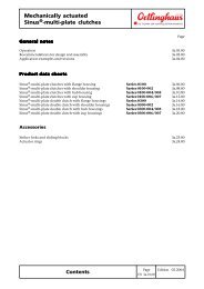
Description Description Beschreibung<br />
The <strong>Hydro</strong>-<strong>flow</strong> hydrodynamic coupling<br />
includes two basic elements: a pump A<br />
and a turbine B, which are both fitted<br />
with radial blades. Pump A is made of<br />
aluminium and is connected to the hollow<br />
shaft by splines.<br />
Ball bearings mounted on the hollow<br />
shaft are mounted in removable steel<br />
bearings, for easy maintenance.<br />
The turbine B is bolted to a half-case C.<br />
The mating face is sealed. The aluminium<br />
delay chamber R may be bolted to<br />
half-case C. The mating face is also<br />
sealed.<br />
All the <strong>Hydro</strong>-<strong>flow</strong> couplings are balanced<br />
dynamically and are all fitted with a<br />
fuse plug which releases the oil when<br />
the oil temperature exceeds +145°C.<br />
Other protective devices may be provided<br />
on request.<br />
Le coupleur hydrodynamique <strong>Hydro</strong><strong>flow</strong><br />
comprend deux éléments de base,<br />
une pompe A et une turbine B, chacun<br />
pourvu d'aubes radiales. La pompe A,<br />
en aluminium, est reliée à l'arbre creux<br />
par des cannelures. Des roulements à<br />
billes, montés sur l'arbre creux, sont<br />
logés dans des paliers amovibles en<br />
acier permettant leur maintenance<br />
aisée.<br />
La turbine B est boulonnée à un demicarter<br />
C. Le plan de joint est rendu<br />
étanche. Eventuellement, la chambre<br />
de retardement en aluminium R, est<br />
boulonnée au demi-carter C. Le plan de<br />
joint est également rendu étanche.<br />
Tous les coupleurs <strong>Hydro</strong>-<strong>flow</strong> sont<br />
équilibrés dynamiquement. Ils sont<br />
munis d'un bouchon fusible qui libère<br />
l'huile lorsque la température d'huile<br />
dépasse +145°C. D'autres systèmes de<br />
protection peuvent être prévus sur<br />
demande.<br />
Die hydrodynamische <strong>Hydro</strong>-<strong>flow</strong><br />
Kupplung besteht aus zwei Haupteilen:<br />
einem Pumpenrad A und einer Turbine<br />
B, die beide mit radialen Schaufeln versehen<br />
sind. Das Pumpenrad A, aus<br />
Aluminium, ist mittels Vielkeilprofil mit<br />
der Hohlwelle verbunden. Die<br />
Kugellager der Hohlwelle sitzen in ausbaubaren<br />
Schildern, so daß die<br />
Wartung erleichtert wird.<br />
Die Turbine B, auch aus Aluminium, ist<br />
mit der Gehäusehälfte C, ebenfalls aus<br />
Aluminium, verschraubt und sicher<br />
abgedichtet. Bedarfsweise kann zusätzlich<br />
eine Verzögerungs-kammer R an<br />
der Gehäusehälfte öldicht angeschraubt<br />
werden.<br />
Alle <strong>Hydro</strong>-<strong>flow</strong> Kupplungen sind dynamisch<br />
ausgewuchtet. Sie werden mit<br />
Schmelzsicherungen ausgerüstet, die<br />
das Öl entweichen lassen, sobald<br />
dieses +145°C erreicht. Andere<br />
Sicherungen sind auf Wunsch erhältlich<br />
Advantages Avantages Vorteile<br />
Off-load start<br />
- Start-up is free from the usual, long<br />
current peaks,<br />
- jamming is impossible,<br />
- Automatic distribution of the load in<br />
case of joint drive by several motors.<br />
Protection of the machine<br />
- Protection against continuous, light<br />
overloads,<br />
- Shock damping.<br />
Starting torque control<br />
Basic version: max. starting torque is<br />
lower than 200% of the nominal torque.<br />
With the delay chamber: the starting<br />
torque is lower than 150 % of the nominal<br />
torque.<br />
Démarrage à vide du moteur<br />
- suppression des pointes de courant<br />
prolongées au démarrage,<br />
- blocage exclu,<br />
- répartition automatique de la charge<br />
en cas d'entraînement conjoint par<br />
plusieurs moteurs.<br />
Protection de la machine<br />
- protection contre les surcharges<br />
légères continues,<br />
- amortissement des chocs.<br />
Contrôle du couple de démarrage<br />
Version de base : Couple de démarrage<br />
maximum inférieur à 200 % du<br />
couple nominal.<br />
Avec chambre de retardement : Couple<br />
de démarrage inférieur à 150 % du<br />
couple nominal<br />
Nahezu lastfreier Anlauf des Motors<br />
- Wegfall verlängerter<br />
Anlaufstromspitzen,<br />
- Blockierung ist ausgeschlossen,<br />
- automatische Lastverteilung bei<br />
Mehrmotorenantrieb.<br />
Schutz der Arbeitsmaschine<br />
- Schutz vor leichter Dauerüberlast,<br />
- Dämpfung von Laststößen.<br />
Kontrolle des Anlaufdrehmomentes<br />
Ausführungen ohne<br />
Verzögerungskammer: Max.<br />
Anlaufdrehmoment geringer als 200 %<br />
des Nenndrehmomentes.<br />
Mit Verzögerungskammer :<br />
Anlaufdrehmoment geringer als 150 %<br />
des Nenndrehmomentes<br />
<strong>Hydro</strong>-<strong>flow</strong> HE<br />
<strong>Hydro</strong>-<strong>flow</strong> HV<br />
4<br />
<strong>Hydro</strong>-<strong>flow</strong> HC<br />
<strong>Hydro</strong>-<strong>flow</strong> HP
<strong>Hydro</strong>-<strong>flow</strong><br />
89201efd641g<br />
Versions Versions Ausfürhungen<br />
HO versions<br />
These versions are used as a baseline<br />
for all the other versions.<br />
HV versions<br />
This version includes a pulley whose<br />
cross-section and number of grooves<br />
are calculated to match the coupling<br />
power.<br />
HE and HC versions<br />
A SURE-flex ® or TEX-O-flex coupling<br />
flange is mounted on the coupling an<br />
allows the torque to be transmitted<br />
through a flexible element allowing<br />
misalignments. The replacement of the<br />
flexible element can be realized without<br />
misalignement of the shafts. The coupler<br />
can also be filled or drained with<br />
the driven machine loaded.<br />
HP versions<br />
A female PENCOflex hub is mounted<br />
on these versions in which the male<br />
hub engages<br />
Exécutions HO<br />
Ces exécutions sont les bases de<br />
toutes les autres exécutions.<br />
Exécutions HV<br />
Ces exécutions comportent une poulie<br />
dont le diamètre, la section et le<br />
nombre de gorges sont calculés pour<br />
la puissance du coupleur.<br />
Exécutions HE et HC<br />
Un plateau d'accouplement<br />
SURE-flex ® ou TEX-O-flex est adapté<br />
sur le coupleur et permet la transmission<br />
du couple par un élément élastique<br />
acceptant des désalignements en<br />
conséquence. Le remplacement des<br />
garnitures élastiques peut être réalisé<br />
sans désaligner les arbres. Le remplissage<br />
du coupleur peut ainsi être réalisé<br />
même si la machine est chargée.<br />
Exécutions HP<br />
Un plateau femelle d'accouplement<br />
PENCOflex est adapté sur ces exécutions<br />
dans lequel vient se loger le plateau<br />
mâle.<br />
Ausführungen HO<br />
Diese sind die Grundausführungen, auf<br />
denen alle Ausführungsvarianten<br />
aufbauen.<br />
Ausführungen HV<br />
Bei diesen ist eine Keilriemenscheibe<br />
angebracht, die in Rillenprofil, -anzahl<br />
und -durchmesser der<br />
Kupplungsleistung entsprechend<br />
ausgelegt ist.<br />
Ausführungen HE und HC<br />
Bei diesen kommen gegenstückseitig<br />
hoch-elastische SURE-flex ® bzw.<br />
TEX-O-flex Kupplungen zur<br />
Verwendung, die aufgrund ihrer<br />
spezifischen Konzepte den Vorteil der<br />
Zulässigkeit relativ großer<br />
Ausrichtfehler bieten. Das Auswechseln<br />
der Elastikelemente kann erfolgen,<br />
ohne deshalb die Wellen versetzen zu<br />
müssen. Entleeren und befüllen der<br />
Kupplung auch bei Belastung der<br />
Maschine<br />
Ausführungen HP<br />
Bei diesen ist das Lochteil einer<br />
PENCOflex Kupplung angeflanscht,<br />
welches ein mit der anderen Welle<br />
verbundenes Bolzenteil gleichen<br />
Kupplungstyps mitnimmt<br />
5
<strong>Hydro</strong>-<strong>flow</strong><br />
89201efd641g<br />
Notes Notes Notizen<br />
6
<strong>Hydro</strong>-<strong>flow</strong><br />
89201efd641g<br />
Operating principles Fonctionnement Funktionsprinzip<br />
<br />
<br />
<br />
<br />
<br />
<br />
<br />
<br />
<br />
<br />
<br />
<br />
<br />
<br />
<br />
Basic model<br />
At startup, pump A which is integral<br />
with the motor forces the oil to move,<br />
under the centrifugal force. The kinetic<br />
energy of the oil is transmitted to<br />
turbine B, thus creating a torque which<br />
tends to rotate the machine shaft.<br />
In steady state, the slight difference in<br />
speed of turbine B with respect to pump<br />
A sustains the oil motion, which produces<br />
a permanent load on the blades, owing<br />
to the oil's kinetic energy. The torque is<br />
thus maintained permanently.<br />
Hence:<br />
- the torque at the driving shaft is equal<br />
to the torque at the driven shaft,<br />
- the rotation speed of the driven element<br />
is always lower than the speed of the<br />
driving element (this difference is called<br />
"slip"),<br />
- the slip depends on the rotation speed,<br />
the transmitted torque and the quantity<br />
of oil in the coupling,<br />
- the power loss is equal to the slip percentage<br />
(2% for large sizes and 6% for<br />
small sizes),<br />
- the <strong>Hydro</strong>-<strong>flow</strong> coupling can rotate<br />
indifferently in any rotation direction,<br />
- the <strong>Hydro</strong>-<strong>flow</strong> coupling can be reversed<br />
under certain conditions (see Drive<br />
from the outside).<br />
With a delay chamber<br />
When the machine is not running, the<br />
delay chamber R contains some of the<br />
oil and thus reduces the quantity of oil<br />
contained in the primary rotor A (see<br />
fig.1).<br />
When the motor is started, the torque<br />
available on the driven machine side is<br />
thus limited, and this allows the motor<br />
to rapidly reach its working speed and<br />
run rapidly across the high current<br />
consumption range. As soon as the<br />
motor is started, the oil slowly comes<br />
out of delay chamber R and fills the<br />
working system (rotor/turbine)(see<br />
fig.2).<br />
When the motor is running at its nominal<br />
speed, the maximum quantity of oil<br />
contributes to the torque transmission,<br />
so that there is only a minimum slip<br />
when the nominal torque is reached<br />
(see fig.3).<br />
<br />
<br />
<br />
<br />
<br />
<br />
<br />
<br />
<br />
<br />
<br />
<br />
<br />
<br />
<br />
<br />
<br />
<br />
<br />
<br />
<br />
<br />
<br />
<br />
<br />
<br />
<br />
<br />
<br />
<br />
<br />
<br />
<br />
<br />
<br />
<br />
<br />
<br />
<br />
<br />
<br />
<br />
<br />
<br />
<br />
<br />
<br />
<br />
<br />
<br />
<br />
<br />
<br />
<br />
<br />
<br />
<br />
<br />
<br />
<br />
<br />
<br />
<br />
<br />
<br />
<br />
<br />
<br />
<br />
<br />
<br />
<br />
<br />
<br />
<br />
<br />
<br />
<br />
<br />
<br />
<br />
<br />
<br />
<br />
<br />
<br />
<br />
<br />
<br />
<br />
<br />
<br />
<br />
<br />
<br />
<br />
<br />
<br />
<br />
<br />
<br />
<br />
<br />
<br />
<br />
<br />
<br />
<br />
<br />
<br />
<br />
<br />
<br />
<br />
<br />
<br />
<br />
<br />
<br />
<br />
<br />
<br />
<br />
<br />
<br />
<br />
<br />
<br />
<br />
<br />
<br />
<br />
B A C R<br />
<br />
<br />
<br />
<br />
<br />
<br />
<br />
<br />
<br />
<br />
<br />
<br />
<br />
<br />
<br />
Modèle de base<br />
Au démarrage, la pompe A, solidaire du<br />
moteur, entraine l'huile, la forçant à se<br />
mettre en mouvement grâce à la force<br />
centrifuge. L'énergie cinétique de l'huile<br />
est transmise à la turbine B, créant<br />
ainsi un couple qui tend à faire tourner<br />
l'arbre machine.<br />
En régime continu, la légère différence<br />
de vitesse de la turbine B par rapport à<br />
la pompe A maintient le mouvement de<br />
l'huile produisant grâce à son énergie<br />
cinétique, un effort permanent sur les<br />
aubes. Le couple est ainsi obtenu en<br />
permanence.<br />
Il en résulte que :<br />
- le couple à l'arbre entraînant est égal<br />
au couple à l'arbre entraîné,<br />
- la vitesse de rotation de l'élément<br />
conduit est toujours inférieure à celle de<br />
l'élément entraînant (la différence de<br />
vitesse est appelée "glissement"),<br />
- le glissement est fonction de la vitesse<br />
de rotation, du couple transmis et de la<br />
quantité d'huile dans le coupleur,<br />
- la perte de puissance est égale au<br />
pourcentage de glissement (2% pour<br />
les grandes et 6% pour les petites<br />
tailles),<br />
- le coupleur <strong>Hydro</strong>-<strong>flow</strong> peut tourner<br />
indifféremment dans les deux sens de<br />
rotation,<br />
- le coupleur <strong>Hydro</strong>-<strong>flow</strong> est réversible<br />
sous certaines conditions (voir<br />
Entrainement par l'extérieur).<br />
Avec chambre de retardement<br />
A l'arrêt, la chambre de retardement R<br />
contient une partie de l'huile et limite<br />
ainsi la quantité d'huile dans la pompe A<br />
(voir fig.1).<br />
Au démarrage du moteur, le couple<br />
disponible du côté de la machine entraînée<br />
est donc limité, permettant au moteur de<br />
prendre rapidement sa vitesse de régime<br />
et de parcourir rapidement la plage de<br />
grande consommation de courant. Dès<br />
le démarrage l'huile sort lentement de la<br />
chambre de retardement R pour remplir<br />
le circuit de travail (rotor/turbine)(voir fig.2).<br />
Lorsque le moteur tourne à sa vitesse<br />
nominale, la quantité d'huile maximum<br />
participe à la transmission du couple,<br />
de manière que le glissement soit au<br />
minimum quand le couple nominal est<br />
atteint (voir fig.3).<br />
<br />
<br />
<br />
<br />
<br />
<br />
<br />
<br />
<br />
<br />
<br />
<br />
<br />
<br />
1 2 3<br />
Grundmodell<br />
Beim Anlaufen übt das mit der treibenden<br />
Welle verbundene Pumpenrad A<br />
auf das Öl eine Zentrifugalkraft aus,<br />
welche den Ölstrom rotieren lässt. Die<br />
so entstandene kinetische Energie<br />
bewirkt an der Turbine B ein<br />
Drehmoment, das die Welle der<br />
Arbeitsmaschine in Drehung bringt.<br />
Im kontinuierlichen Betrieb hält die<br />
geringe Drehzahldifferenz zwischen der<br />
Turbine B und dem Pumpenrad A den<br />
Ölstrom aufrecht, so daß die gehaltene<br />
kinetische Energie eine ständige Kraft<br />
auf die Schaufeln ausübt und die<br />
Drehmomentübertragung permanent<br />
erhalten bleibt.<br />
Daraus resultiert :<br />
- das Drehmoment an der treibenden<br />
Welle ist zu jeder Zeit gleich dem an<br />
der getriebenen Welle,<br />
- die Drehzahl des getriebenen Wellenstranges<br />
ist immer ein wenig kleiner als die<br />
des treibenden (diese Drehzahldifferenz ist<br />
der Schlupf der Kupplung),<br />
- der Schlupf ist von der Drehzahl, von<br />
dem übertragenen Drehmoment und von<br />
der Ölmenge in der Kupplung abhängig,<br />
- der Leistungsverlust ist prozentisch<br />
gleich dem Schlupf (2% bei den großen,<br />
bis 6% bei den kleinen Kupplungsgrößen),<br />
- die <strong>Hydro</strong>-<strong>flow</strong> Kupplung ist für beide<br />
Drehsinne geeignet,<br />
- die <strong>Hydro</strong>-<strong>flow</strong> Kupplung kann unter<br />
bestimmten Voraussetzungen auch für<br />
entgegengesetzten Kraftfluß (siehe<br />
Aussenantrieb) eingesetzt werden.<br />
Mit Verzögerungskammer<br />
Bei Stillstand befindet sich ein Teil der<br />
Ölfüllung in der Verzögerungskammer R,<br />
so daß die Ölmenge im Pumpenrad A<br />
geringer ist (siehe Abb.1).<br />
Beim Anlaufen ist somit das verfügbare<br />
Drehmoment an der Seite der Arbeitsmaschine<br />
noch mehr begrenzt, so daß<br />
der Motor seine Betriebsdrehzahl schnell<br />
erreichen kann und den Bereich der<br />
großen Stromaufnahme schnell durchläuft.<br />
Gleichzeitig fließt das Öl von der<br />
Verzögerungskammer R inden<br />
Arbeitsraum von Pumpe/Turbine (siehe<br />
Abb. 2). Wenn der Motor seine Nenndrehzahl<br />
erreicht hat, wirkt die dann größte<br />
Ölmenge im Arbeitsraum bei der<br />
Drehmomentübertragung so, daß der<br />
Schlupf am geringsten ist, wenn die<br />
Kupplung ihr Nenndrehmoment erreicht<br />
(siehe Abb.3).<br />
7
Effect on the electric<br />
motor<br />
<strong>Hydro</strong>-<strong>flow</strong><br />
Effet sur le moteur<br />
électrique<br />
Wirkung auf den<br />
Elektromotor<br />
89201efd641g<br />
When a squirrel-cage motor, mounted<br />
directly on a machine with a high inertia<br />
is started, a substantial current surge is<br />
generated for a long period. This period<br />
may be divided into two parts : the<br />
motors rotor startup period and the<br />
machine startup period.<br />
With an <strong>Hydro</strong>-<strong>flow</strong> coupling now fitted,<br />
the current absorbed by the motor during<br />
the machine startup phase is going to be<br />
reduced. With the <strong>Hydro</strong>-<strong>flow</strong> coupling,<br />
the motor can start as if there were no<br />
load. In this phase, the oil is not yet<br />
fully moving and the torque transmitted<br />
to the shaft of the driven machine is<br />
increasing slowly. This phenomenon is<br />
even more sensitive when a delay<br />
chamber is added. Thus the motor startup<br />
current I H or I R is reduced immediately.<br />
At motor speed n L , the machine starts<br />
when T H or T R > T L . The slipping of the<br />
coupling decreases gradually as the driven<br />
machines speed increases until the<br />
working speed n N is reached.<br />
For starting machines with high inertia,<br />
such as conveyor belts and fans, the<br />
<strong>Hydro</strong>-<strong>flow</strong> makes it possible to use<br />
motors of smaller sizes (reduced starting<br />
current and improvement of the power<br />
factor cos j).<br />
Then installing costly equipment becomes<br />
useless. Judicious selection of the oil<br />
filling level also makes it possible to<br />
influence the startup time.<br />
Le démarrage d'un moteur à cage monté<br />
directement sur une machine à forte<br />
inertie provoque un appel de courant<br />
important pendant une longue période.<br />
Cette période peut se décomposer en<br />
deux parties : la partie de démarrage<br />
du rotor du moteur et la partie de<br />
démarrage de la machine.<br />
L'installation d'un coupleur <strong>Hydro</strong>-<strong>flow</strong><br />
va permettre de réduire la valeur de<br />
l'intensité absorbée par le moteur durant<br />
la phase de démarrage de la machine.<br />
En effet, avec un coupleur <strong>Hydro</strong>-<strong>flow</strong>,<br />
le moteur démarre comme si il n'y avait<br />
pas de charge. Dans cette phase,<br />
l'huile n'est pas encore entièrement<br />
mise en mouvement et le couple transmis<br />
à l'arbre de la machine entraînée<br />
croît peu à peu. Ce phénomène est<br />
encore plus sensible avec l'adjonction<br />
d'une chambre de retardement. Ainsi, le<br />
courant de démarrage I H ou I R du<br />
moteur se trouve réduit immédiatement.<br />
A la vitesse n L du moteur, la machine<br />
démarre lorsque T H ou T R > T L . Le<br />
glissement du coupleur diminue graduellement<br />
tandis que la vitesse de la<br />
machine entraînée augmente jusqu'à ce<br />
que la vitesse de régime n N soit atteinte.<br />
Pour le démarrage de machines à forte<br />
inertie comme par exemple les transporteurs<br />
à bande et les ventilateurs, l'utilisation<br />
d'un coupleur <strong>Hydro</strong>-<strong>flow</strong> permet le<br />
choix d'un moteur de taille inférieure<br />
(réduction du courant de démarrage et<br />
amélioration du facteur de puisssance<br />
cos j).<br />
L'installation d'appareils coûteux<br />
devient inutile. La sélection judicieuse du<br />
remplissage d'huile permet, de plus, d'influencer<br />
le temps de démarrage.<br />
Der Anlauf eines direkt mit einer<br />
Maschine mit großem Massenträgheitsmoment<br />
verbundenen Drehstrom-<br />
Käfigläufermotors bewirkt eine hohe<br />
Stromaufnahme während einer langen<br />
Zeitspanne. Diese Zeitspanne kann in<br />
zwei Phasen unterteiltwerden: in die<br />
Anlaufphase des Motorrotors und in die<br />
Anlaufphase der Maschine.<br />
Durch den Einbau einer <strong>Hydro</strong>-<strong>flow</strong><br />
Kupplung wird eine Reduzierung der<br />
Stromaufnahmewerte während der<br />
Maschinenanlaufphase erreicht. Mit der<br />
<strong>Hydro</strong>-<strong>flow</strong> Kupplung startet der<br />
Motorpraktisch ohne Last. In dieser<br />
Phase kommt das Öl erstzunehmend in<br />
Strömung, so daß das an die Welle der<br />
angetriebenen Maschine gegebene<br />
Drehmoment nur allmählich steigt. Bei<br />
denAusführungen mit Verzögerungskammer<br />
ist das Anlaufmoment noch<br />
weiter herabgesetzt. Der Aufnahmestrom<br />
I H bzw. I R des Motors ist somit durch<br />
diegeringeren Anlaufmomente T H bzw.<br />
T R unmittelbar reduziert.<br />
Bei einer Motordrehzahl n L läuft die<br />
Arbeitsmaschine an, wennT H oder T R<br />
größer als T L ist. Der Schlupf nimmt<br />
allmählich ab,während die angetriebene<br />
Maschine bis zur Erreichung der<br />
Betriebsdrehzahl n N beschleunigt wird.<br />
Für den Start von Maschinen mit<br />
großen Massenträgheitsmomenten, wie<br />
z.B. von Transportanlagen oder schweren<br />
Ventilatoren, kann durch den<br />
Einsatz einer <strong>Hydro</strong>-<strong>flow</strong> Kupplung eine<br />
kleinere Motorgröße gewählt werden<br />
(Beschränkung von Anlaufstrom und<br />
Verbesserung von Leistungsfaktor cos j)<br />
und eskönnen kostspielige<br />
Starthilfseinrichtungen entfallen.<br />
Durch eine genaue Abstimmung der<br />
Ölfüllmenge kann darüberhinaus die<br />
Anlaufzeit geregelt werden.<br />
I<br />
TH(s=100%)<br />
TR(s=100%)<br />
TH(s=sN%)<br />
Symbols<br />
t = time (s)<br />
n = speed (min-1)<br />
I = current (A)<br />
T = torque (Nm)<br />
s = slip (%)<br />
M = motor<br />
H = without chamber R = with chamber<br />
L = load<br />
N = nominal<br />
Symboles<br />
t = temps (s)<br />
n = vitesse de rotation (min-1)<br />
I = courant (A)<br />
T = couple (Nm)<br />
s = glissement (%)<br />
M = moteur<br />
H = sans chambre R = avec chambre<br />
L = charge N = nominal<br />
Formelzeichen<br />
t = Zeit (s)<br />
n = Drehzahl (min-1)<br />
I = Strom (A)<br />
T = Drehmoment (Nm)<br />
s = Schlupf (%)<br />
M = Motor<br />
H = ohne Kammer R = mit Kammer<br />
L = Belastung N = Nennwert<br />
8
Effect on the driven<br />
machine<br />
<strong>Hydro</strong>-<strong>flow</strong><br />
Effet sur la machine<br />
Wirkung auf die<br />
Arbeitsmaschine<br />
89201efd641g<br />
Curves T R and T H , for coupling with and<br />
without delay chamber, represent the<br />
torque transmitted to the driven<br />
machines shaft. The curves illustrate<br />
the favourable impact the <strong>Hydro</strong>-<strong>flow</strong><br />
coupling has during startup. The<br />
maximum torque T H is much lower than<br />
the motors peak torque.<br />
In this case the <strong>Hydro</strong>-<strong>flow</strong> coupling<br />
really behaves as a torque limiter.<br />
Moreover, if the machine is jammed, the<br />
motors inertia is neutralized automatically.<br />
Depending on the oil level, and the<br />
selection of the <strong>Hydro</strong>-<strong>flow</strong> coupling, the<br />
starting torque may be between 1.2 and<br />
1.5 times the nominal torque, with the<br />
delay chamber, and between 1.5 and 2<br />
times without the chamber.<br />
When the machine is jammed, the<br />
maximum torque with or without the<br />
chamber is twice the nominal torque.<br />
Les courbes T R et T H pour coupleurs<br />
avec et sans chambre de retardement,<br />
représentent le couple communiqué à<br />
l'arbre de la machine entraînée. Elles<br />
illustrent l'influence favorable du coupleur<br />
<strong>Hydro</strong>-<strong>flow</strong> durant le temps de<br />
démarrage. Le couple maximum T H est<br />
bien inférieur au couple de pointe du<br />
moteur.<br />
Dans ce cas le coupleur <strong>Hydro</strong>-<strong>flow</strong> se<br />
comporte comme un limiteur de couple.<br />
De plus, lors d'un blocage éventuel de<br />
la machine, l'inertie du moteur se trouve<br />
neutralisée.<br />
Suivant le remplissage d'huile et la<br />
sélection du coupleur <strong>Hydro</strong>-<strong>flow</strong>, le<br />
couple de démarrage peut se situer<br />
entre 1,2 et 1,5 fois le couple nominal<br />
avec chambre de retardement et entre<br />
1,5 et 2 fois sans chambre de retardement.<br />
Au blocage de la machine, le couple<br />
maximum, avec ou sans chambre, est<br />
égal à deux fois le couple nominal.<br />
Die Kennlinien T R bzw. T H stellen für<br />
Kupplungen mit undohne<br />
Verzögerungskammer den Verlauf des<br />
an die Welle derArbeitsmaschine<br />
gegebenen Dreh-momentes dar. Sie<br />
zeigen dengünstigen Einfluß der <strong>Hydro</strong>-<strong>flow</strong><br />
Kupplung während der Anlaufphase. Die<br />
Höchstdrehmomente T H bzw. T R sind<br />
viel geringer als das<br />
Spitzendrehmoment des Motors.<br />
Die <strong>Hydro</strong>-<strong>flow</strong> Kupplung verhält sich in<br />
diesem Fall also wie ein Drehmomentbegrenzer.<br />
Hinzu kommt, daß bei einer<br />
möglichen Blockierung der Arbeitsmaschine<br />
das Trägheitsmoment des Motors<br />
neutralisiert wird.<br />
Abhängig vom Ölfüllungsgrad und von<br />
der Größenauslegung der<strong>Hydro</strong>-<strong>flow</strong><br />
Kupplung, kann deren Anlaufdrehmoment<br />
bei denAusführungen mit Verzögerungskammer<br />
zwischen dem 1,2- bis 1,5-<br />
fachen und bei jenen ohne<br />
Verzögerungs-kammer zwischen dem<br />
1,5- und 2-fachen ihres<br />
Nenndrehmomentes liegen.<br />
Bei Blockierung der Arbeitsmaschine ist<br />
ihr Maximaldrehmoment beiallen<br />
Ausführungsvarianten dem 2-fachen<br />
ihres Nenndrehmomentesgleichzusetzen.<br />
Protective devices Dispositifs de protection Überlastschutzvorrichtungen<br />
Hydraulic couplings, although different<br />
from torque limiters, are safety components<br />
capable of protecting the motor and the<br />
machine.<br />
Heating of hydraulic couplings directly<br />
which in turns depends on the transmitted<br />
torque. In case of continuous application<br />
of an excessive torque, the coupling's<br />
temperature may exceed that tolerated<br />
by the oil, the seals and the bearings.<br />
To prevent this, fusible plugs should be<br />
installed. All installed, operation-ready<br />
couplings should be fitted with at least<br />
one fusible plug.<br />
There are two types of fusible plugs :<br />
the standard fusible plug and the<br />
percussion fusible plug (see Fusible<br />
plugs).<br />
In addition to a standard fusible plug, or<br />
event an percussion fusible plug, an<br />
output speed controller can be installed<br />
(see Rotational speed controller). This<br />
equipment monitors the coupling's temperature<br />
by simply reading slippage.<br />
Important : for safety reasons, a<br />
protective case must be provided around<br />
the coupling. This must incorporate a<br />
drip tray with a capacity equal to or<br />
greater than that of the coupling.<br />
Les coupleurs hydrauliques, sans être<br />
assimilables à des limiteurs de couple,<br />
sont des organes de sécurité capables<br />
de protéger le moteur et la machine.<br />
L’échauffement des coupleurs<br />
hydrauliques dépend directement du<br />
glissement de celui-ci, lui même<br />
dépendant du couple transmis. En<br />
cas de surcouple continu, la température<br />
du coupleur peut excéder celle admise<br />
par l’huile, les joints et les roulements.<br />
Pour éviter cela, il est nécessaire<br />
d’installer des bouchons fusibles. Tout<br />
coupleur installé et prêt à fonctionner<br />
doit être muni d’au moins un bouchon<br />
fusible.<br />
Il existe deux types de bouchons<br />
fusibles : le bouchon fusible standard et<br />
le bouchon fusible à percussion (voir<br />
Bouchons fusibles).<br />
En complément d’un bouchon fusible<br />
standard voire à percussion, il est possible<br />
d’installer un contrôleur de vitesse<br />
de sortie (voir Contrôleur de vitesse de<br />
rotation). Cet appareil contrôle la<br />
température du coupleur par une simple<br />
lecture du glissement de celui-ci.<br />
Important : Par mesure de sécurité,<br />
un carter de protection enveloppant<br />
le coupleur doit être prévu. Celui-ci doit<br />
être équipé d'un bac de récupération<br />
d'une capacité égale ou supérieure à<br />
celle du coupleur.<br />
<strong>Hydro</strong>dynamische Kupplungen können,<br />
obwohl sie im strikten Sinn keine<br />
Drehmomentbegrenzungs- (Sicherheits-)<br />
kupplungen sind, den Motor und die<br />
Maschine vor Überlastung schützen.<br />
Die Erwärmung der <strong>Hydro</strong>-Kupplung<br />
steht in einem direkten Verhältnis zu<br />
ihrem Schlupf, der vom übertragenen<br />
Drehmoment abhängt. Bei andauernder<br />
Überlast könnte die<br />
Temperaturentwicklung zu einer Überschreitung<br />
der für das Öl, die Dichtringe<br />
und die Lager zulässigen Werte führen.<br />
Um dies zuverlässig zu verhindern, wird<br />
jede Kupplung mit Schmelzsicherungen<br />
versehen.<br />
Es bestehen zwei Ausführungen : die<br />
Standard-Schmelzsicherung und die<br />
Schmelzsicherung mit Schlagbolzen für<br />
thermischen Überlastschutz (siehe<br />
Schmelzsicherungen).<br />
In Ergänzung dieser Schmelzsicherungen<br />
kann zur Überwachung der Ausgangsdrehzahl<br />
ein berührungsloser Überlastwächter<br />
(siehe Berührungsloser<br />
Überlastwächter) mitgeliefert werden.<br />
Dieser gestattet die Temperaturüberwachung<br />
der Kupplung durch eine elektronische<br />
Kontrolle ihres Schlupfes.<br />
Wichtig : Dem Ausspritzen von heissem<br />
Öl ist unbedingt Vorsorge zu tragen;<br />
insbesondere muß um die Kupplung eine<br />
geeignete Schutzhaube, ausgestattet<br />
mit einem Auffangbehälter mindestens<br />
gleichen Inhalts als die Ölfüllmenge der<br />
Kupplung, vorgesehen sein.<br />
9
Drive from the outside<br />
<strong>Hydro</strong>-<strong>flow</strong><br />
Entraînement par<br />
l’extérieur<br />
Aussenantrieb<br />
89201efd641g<br />
Unless otherwise specified, the <strong>Hydro</strong>-<strong>flow</strong><br />
hydrodynamic coupling is delivered for<br />
direct installation on the drive shaft<br />
(= normal arrangement).<br />
In certain cases, such as complete jamming<br />
of the machine or the need to control<br />
the coupling manually for filling purposes,<br />
it may be useful to reverse installation,<br />
i.e. for the coupler to be driven from the<br />
outside.<br />
This also allows more effective cooling<br />
in operation with repeated overload<br />
situations.<br />
Outer rotor B becomes the pump and<br />
inner rotor A becomes the turbine.<br />
From the size 350, these two parts do<br />
not have identical blade shapes, this<br />
should be specified when ordering.<br />
Otherwise, the coupling will be delivered<br />
for normal arrangement and will not correctly<br />
fulfil its purpose as a start-up<br />
torque limiter.<br />
A coupling with pulley (HV and HVR)<br />
can be driven from the outside if the<br />
transmission ratio is 1:1 (call for details).<br />
In case of drive from the outside for<br />
couplings with a brake disc or drum<br />
(H.D. or H.B.) consult us.<br />
For any request for a coupling driven<br />
from the outside, add "E" to the code<br />
(see Coding).<br />
<br />
<br />
<br />
<br />
<br />
<br />
<br />
<br />
<br />
<br />
<br />
<br />
<br />
<br />
<br />
<br />
<br />
<br />
<br />
<br />
<br />
<br />
<br />
<br />
<br />
<br />
<br />
<br />
<br />
<br />
<br />
<br />
<br />
<br />
<br />
<br />
<br />
<br />
<br />
<br />
<br />
<br />
<br />
<br />
<br />
<br />
<strong>Hydro</strong>-<strong>flow</strong> coupling, normal arrangement,<br />
HP/HPR arrangements<br />
<br />
<br />
<br />
<br />
<br />
Sans indication particulière, le coupleur<br />
hydrodynamique <strong>Hydro</strong>-<strong>flow</strong> est livré<br />
pour être monté directement sur l’arbre<br />
entraînant (= disposition normale).<br />
Dans certains cas, comme par exemple<br />
le risque de blocage complet de la<br />
machine ou la nécessité de manoeuvrer<br />
le coupleur manuellement pour son<br />
remplissage, il peut être utile d’inverser<br />
son montage, c’est à dire que le coupleur<br />
soit entraîné par l'extérieur.<br />
Cela permet également, un refroidissement<br />
plus efficace en fonctionnement avec<br />
surcharges répétées.<br />
Le rotor extérieur B devient la pompe et<br />
le rotor intérieur A devient la turbine. A<br />
partir de la taille 350, ces deux parties<br />
n’ayant pas une forme des aubes tout à<br />
fait identiques, il est nécessaire de le<br />
signaler à la commande. Si cela n’est<br />
pas le cas, le coupleur sera livré pour<br />
disposition normale et ne jouera pas<br />
correctement son rôle de limiteur de<br />
couple de démarrage.<br />
Un coupleur avec poulie (HV et HVR)<br />
pourra être entraîné par l'extérieur si le<br />
rapport de transmission est de 1:1<br />
(Nous consulter).<br />
En cas d’entraînement par l’extérieur<br />
pour les coupleurs dotés d’un disque ou<br />
tambour de frein (H.D ou H.B) nous<br />
consulter.<br />
Pour toute demande de coupleur entraîné<br />
par l'extérieur, rajouter à la codification du<br />
coupleur la mention "E" (voir<br />
Codification).<br />
<br />
<br />
<br />
<br />
<br />
<br />
<br />
<br />
<br />
<br />
<br />
<br />
<br />
<br />
<br />
<br />
<br />
<br />
<br />
<br />
Coupleur <strong>Hydro</strong>-<strong>flow</strong>, disposition normale,<br />
exécutions HP/HPR.<br />
Ohne besonderen Hinweis wird die<br />
hydrodynamische <strong>Hydro</strong>-<strong>flow</strong> Kupplung für<br />
eine Anordnung direkt auf der Motorwelle<br />
(= Normalanordnung) vorgesehen und<br />
geliefert.<br />
In manchen Fällen, wie bei nicht auszuschließender<br />
Gefahr der völligen<br />
Blockierung der Maschine, oder der<br />
Notwendigkeit die Kupplung zwecks ihrer<br />
Füllung drehen zu können, kann es jedoch<br />
erforderlich sein, die <strong>Hydro</strong>-Kupplung<br />
auf der Maschinenwelle anzuordnen<br />
(=Aussenantrieb).<br />
Dieses führt auch zu einer besseren<br />
Kühlung der <strong>Hydro</strong>-Kupplung, insbesondere<br />
bei Betriebszyklen mit häufigen und<br />
hochlastigen Anläufen, weil dann ihr<br />
Mantel bereits mit dem Motor dreht.<br />
Da so das Aussenrad B zur Pumpe und<br />
das mit der Hohlwelle ausgeführte<br />
Innenrad A zur Turbine wird und, ab<br />
Größe 350, diese Funktionsumkehrung<br />
einige Teileanpas-sungen bedingt, ist es<br />
unerlässlich bei Bestellung auf einen<br />
vorgesehenen Aussenantrieb hinzuweisen;<br />
anderenfalls würde die Kupplung<br />
für Normal-anordnung geliefert werden<br />
und ihre Funktion als drehmomentbegrenzende<br />
Anlaufkupplung nicht korrekt<br />
erfüllen.<br />
Die Ausführungen mit<br />
Keilriemenscheibe (HV und HVR) sind<br />
auch mit Aussenantrieb einsetzbar,<br />
vorausgesetzt das Übersetzungsverhältnis<br />
des Keilriemenantriebes beträgt 1:1<br />
(Anfrage erbeten).<br />
In der Lage das Aussenantrieb der<br />
Kupplung mit einer Bremsscheibe oder<br />
Bremmstrommel (H.D oder H.B) bitte<br />
rückfragen.<br />
Als Hinweis für vorgesehenen<br />
Aussenantrieb ist der Bezeichnung der<br />
<strong>Hydro</strong>-<strong>flow</strong> Kupplung (siehe Bezeichnung)<br />
ein "E" anzufügen.<br />
<strong>Hydro</strong>-<strong>flow</strong> Kupplung, Normalanordnung,<br />
Ausführungen HP/HPR.<br />
<br />
<br />
<br />
<br />
<br />
<br />
<br />
<br />
<br />
<br />
<br />
<br />
<br />
<br />
<br />
<br />
<br />
<br />
<br />
<br />
<br />
<br />
<br />
<br />
<br />
<br />
<br />
<br />
<br />
<br />
10<br />
<br />
<br />
<br />
<br />
<br />
<br />
<br />
<br />
<br />
<br />
<br />
<br />
<br />
<br />
<br />
<br />
<br />
<br />
<br />
<br />
<br />
<br />
<br />
<br />
<br />
<br />
<br />
<br />
<br />
<br />
<br />
<br />
<br />
<br />
<br />
<br />
<br />
<br />
<br />
<br />
<br />
<br />
<br />
<br />
<br />
<br />
<br />
<br />
<br />
<br />
<br />
<br />
<br />
<br />
<br />
<br />
<br />
<br />
<br />
<br />
<br />
<br />
<br />
<br />
<br />
<br />
<br />
<br />
<br />
<br />
<br />
<br />
<br />
<br />
<br />
<br />
<br />
<br />
<br />
<br />
<br />
<br />
<br />
<br />
<br />
<br />
<br />
<br />
<br />
<br />
<br />
<br />
<strong>Hydro</strong>-<strong>flow</strong> coupling, driven from the<br />
outside, HP/HPR...E arrangements.<br />
Coupleur <strong>Hydro</strong>-<strong>flow</strong>, entraînement par<br />
l'extérieur, exécutions HP/HPR....E.<br />
<strong>Hydro</strong>-<strong>flow</strong> Kupplung, mit Aussenantrieb,<br />
Ausführungen HP/HPR....E.
<strong>Hydro</strong>-<strong>flow</strong><br />
89201efd641g<br />
Vertical shafts Arbres verticaux Vertikale Wellen<br />
General<br />
Under certain conditions, <strong>Hydro</strong>-<strong>flow</strong><br />
hydrodynamic couplings can be installed<br />
in a position other than horizontal.<br />
Correct operation in the vertical position<br />
is only guaranteed if the pump is placed<br />
in the bottom position, whether drive is<br />
from the inside or the outside (see<br />
Drive from the outside).<br />
Motor on top and drive from the<br />
inside :<br />
Whether used with or without a delay<br />
chamber, this position poses no special<br />
problem by requires internal arrangements.<br />
A version with pulley (HV/HVR) is also<br />
offered.<br />
Add "V1" to the code.<br />
Motor on top and drive from the<br />
outside :<br />
In this position the delay chamber serves<br />
no purpose and the pulley version can<br />
be used if the coupler is mounted on<br />
the machine shaft.<br />
Add "V2" to the code.<br />
Motor at the bottom and drive from<br />
the inside :<br />
This position is only of interest when<br />
filling arrangements A to C (see Filling)<br />
are suitable, as the pump is located at<br />
the top.<br />
A delay chamber serves no purpose.<br />
The version with pulley (HV), however,<br />
is offered.<br />
Add "V3" to the code.<br />
Motor at the bottom and drive from<br />
the outside :<br />
This position is not offered.<br />
Généralités<br />
Les coupleurs hydrodynamiques <strong>Hydro</strong>-<strong>flow</strong><br />
sous certaines conditions, peuvent être<br />
installés dans une position autre que<br />
l’horizontale.<br />
Un fonctionnement correct en position<br />
verticale n’est assuré que si la pompe<br />
est placée en bas, que l'entraînement<br />
soit fait par l'intérieur ou par l'extérieur<br />
(Voir Entraînement par l'extérieur).<br />
Moteur au dessus et entraînement<br />
par l'intérieur :<br />
Que ce soit avec ou sans chambre de<br />
retardement, cette position ne pose pas<br />
de problème particulier mais nécessite<br />
des aménagements internes.<br />
La version avec poulie (HV/HVR) est<br />
également réalisable.<br />
À la codification, rajouter la mention<br />
"V1".<br />
Moteur au dessus et entraînement<br />
par l'extérieur :<br />
Dans cette position la chambre de<br />
retardement n’est d’aucune utilité et la<br />
version à poulie est possible si le coupleur<br />
est monté sur l’arbre de la machine.<br />
À la codification, rajouter la mention<br />
"V2".<br />
Moteur en dessous et entraînement<br />
par l'intérieur :<br />
Cette position n’est valable que lorsque<br />
les remplissages A à C (voir Remplissage)<br />
conviennent car la pompe est placée en<br />
haut.<br />
Une chambre de retardement n’est<br />
d’aucune utilité. Par contre, la version à<br />
poulie (HV) est faisable.<br />
À la codification, rajouter la mention<br />
"V3".<br />
Moteur en dessous et entraînement<br />
par l'extérieur :<br />
Cette position n’est pas admise.<br />
Allgemeines<br />
Die hydrodynamischen <strong>Hydro</strong>-<strong>flow</strong><br />
Kupplungen können auch in anderen<br />
Einbaulagen als horizontal eingesetzt<br />
werden.<br />
In solchen Lagen ist ihre<br />
Betriebsfunktion jedoch nur dann ohne<br />
Einschränkungen gegeben, wenn das<br />
als Pumpe wirkende Rad unterhalb der<br />
Turbine liegt, sei dies bei Innen- oder<br />
Aussenantrieb (siehe Aussenantrieb).<br />
Motor oberhalb und Innenantrieb :<br />
Diese Lage ist für alle Ausführungen -<br />
mit oder ohne Verzögerungskammer -<br />
zulässig, bedingt aber einige interne<br />
Teileanpassungen.<br />
Die Ausführungen mit Keilriemenscheibe<br />
(HV/HVR) sind zulässig.<br />
In der Kupplungsbezeichnung ist der<br />
Lagehinweis "V1" mitaufzuführen.<br />
Motor oberhalb und Aussenantrieb :<br />
Bei dieser Einbaulage sind Verzögerungskammern<br />
von keinem Nutzen. Die<br />
Ausführung mit Keilriemenscheibe ist<br />
zulässig when die Kupplung auf der<br />
Maschinenwelle eingestellt ist.<br />
In der Kupplungsbezeichnung ist der<br />
Lagehinweis "V2" mitaufzuführen.<br />
Motor unterhalb und Innenantrieb :<br />
Diese Einbaulage ist nur zulässig bei<br />
passenden Ölfüllmengen A bis C (siehe<br />
Füllung), da das Pumpenrad oberhalb<br />
der Turbine liegt.<br />
Verzögerungskammern sind von keinem<br />
Nutzen. Die Ausführung mit<br />
Keilriemen-scheibe (HV) ist zulässig.<br />
In der Kupplungsbezeichnung ist der<br />
Lagehinweis "V3" mitaufzuführen.<br />
Motor unterhalb und Aussenantrieb :<br />
Diese Lage-/Anordnungskombination ist<br />
ausnahmslos unzulässig.<br />
<br />
<br />
<br />
<br />
<br />
<br />
<br />
<br />
<br />
<br />
<br />
<br />
<br />
<br />
<br />
<br />
<br />
<br />
<br />
<br />
<br />
<br />
<br />
<br />
<br />
<br />
<br />
<br />
<br />
<br />
<br />
<br />
<br />
<br />
<br />
<br />
<br />
<br />
<br />
<br />
<br />
<br />
<br />
<br />
<br />
<br />
<br />
<br />
<br />
<br />
<br />
<br />
<br />
<br />
<br />
<br />
<br />
<br />
<br />
<br />
<br />
<br />
<br />
<br />
<br />
<br />
<br />
<br />
<br />
<br />
<br />
<br />
<br />
<br />
<br />
<br />
<br />
<br />
<br />
<br />
<br />
<br />
<br />
<br />
<br />
<br />
<br />
<br />
<br />
<br />
<br />
<br />
<br />
<br />
<br />
<br />
<br />
<br />
<br />
<br />
<br />
<br />
<br />
<br />
<br />
<br />
<br />
<br />
<br />
<br />
<br />
<br />
<br />
<br />
<br />
<br />
<br />
<br />
<br />
<br />
<br />
<br />
<br />
<br />
<br />
<br />
<br />
<br />
<br />
<br />
<br />
<br />
<br />
<br />
<br />
<br />
<br />
<br />
<br />
<br />
<br />
<br />
<br />
<br />
<br />
<br />
<br />
<br />
<br />
<br />
<br />
<br />
<br />
<br />
<br />
<br />
<br />
<br />
<br />
<br />
<br />
<br />
<br />
<br />
<br />
<br />
<br />
<br />
<br />
<br />
<br />
<br />
<br />
<br />
<br />
<br />
<br />
<br />
<br />
<br />
<br />
<br />
<br />
<br />
<br />
<br />
<br />
<br />
<br />
<br />
<br />
<br />
<br />
<br />
<br />
<br />
<br />
<br />
<br />
<br />
<br />
<br />
<br />
<br />
<br />
<br />
<br />
<br />
<br />
<br />
<br />
<br />
<br />
<br />
<br />
<br />
<br />
<br />
<br />
<br />
<br />
<br />
<br />
<br />
<br />
<br />
<br />
<br />
<br />
<br />
<br />
<br />
<br />
<br />
<br />
<br />
<br />
<br />
<br />
<br />
<br />
<br />
<br />
<br />
<br />
<br />
<br />
<br />
<br />
<br />
<br />
<br />
<br />
<br />
<br />
<br />
<br />
<br />
<br />
<br />
<br />
<br />
<br />
<br />
<br />
<br />
<br />
<br />
<br />
<br />
<br />
<br />
<br />
<br />
<br />
<br />
<br />
<br />
<br />
<br />
<br />
<br />
<br />
<br />
<br />
<br />
<br />
<br />
<br />
<br />
<br />
<br />
<br />
<br />
<br />
<br />
<br />
<br />
<br />
<br />
V1 V2 V3<br />
<br />
<br />
<br />
<br />
<br />
<br />
<br />
<br />
<br />
<br />
<br />
<br />
<br />
<br />
<br />
<br />
<br />
<br />
<br />
<br />
<br />
<br />
<br />
<br />
<br />
<br />
<br />
<br />
<br />
<br />
<br />
<br />
<br />
<br />
<br />
<br />
<br />
<br />
<br />
<br />
<br />
<br />
<br />
<br />
<br />
<br />
<br />
<br />
<br />
<br />
<br />
<br />
<br />
<br />
<br />
<br />
<br />
11
<strong>Hydro</strong>-<strong>flow</strong><br />
89201efd641g<br />
Selection Sélection Auswahl<br />
kW 2000<br />
An <strong>Hydro</strong>-<strong>flow</strong> coupling may be selected<br />
in two different ways :<br />
Selection for IEC motors<br />
For each size of IEC motor, the table<br />
of the main catalogue section gives the<br />
size of the corresponding <strong>Hydro</strong>w-Flow<br />
coupling according to the power to<br />
transmit and the applicable rotation<br />
speed.<br />
For the hollow shaft <strong>Hydro</strong>-<strong>flow</strong> couplings<br />
(with or without delay chamber) and for<br />
the corresponding versions with a delay<br />
chamber, the preferred bores D1 are<br />
recalled separately in the dimensional<br />
drawings and correspond to the diameters<br />
of the IEC motors' shaft ends.<br />
The HV and HVR <strong>Hydro</strong>-<strong>flow</strong> couplings<br />
are indicated in the table shown on the<br />
dimensional drawing, with standardgroove<br />
pulleys selected according to<br />
the driving powers to transmit.<br />
Selection for other motors or according<br />
to the power required<br />
On the diagram below, the input speeds<br />
and the powers in kW are shown on the<br />
X and Y axes, respectively. The various<br />
areas give the field of application for the<br />
successive sizes of couplings shown in<br />
these areas.<br />
DO NOT USE SERVICE FACTOR.<br />
Note : in case of frequent startups or<br />
substantial overloads (more than 5 per<br />
hour), and for ambient temperatures<br />
higher than 40 °C or for an installation<br />
at more than 1000 m over see, please<br />
consult us for checking the coupling<br />
thermal power.<br />
La sélection d'un coupleur <strong>Hydro</strong>-<strong>flow</strong><br />
peut se faire de deux manières :<br />
Sélection pour moteurs CEI<br />
Le tableau du catalogue général, donne,<br />
pour chaque taille de moteur CEI, la taille<br />
de coupleur <strong>Hydro</strong>-<strong>flow</strong> correspondante<br />
en fonction de la puissance à transmettre<br />
et de la vitesse de rotation.<br />
Pour les coupleurs <strong>Hydro</strong>-<strong>flow</strong> à arbre<br />
creux (avec ou sans chambre de<br />
retardement), ainsi que pour les exécutions<br />
correspondantes avec chambre de<br />
retardement, les alésages préférentiels<br />
D1 sont repris séparément dans les<br />
plans d'encombrement et correspondent<br />
avec les diamètres des bouts d'arbre<br />
des moteurs CEI.<br />
Les coupleurs <strong>Hydro</strong>-<strong>flow</strong> HV et HVR<br />
sont donnés dans le tableau du plan<br />
d'encombrement avec des poulies à<br />
gorges standard, sélectionnées suivant<br />
les puissances motrices à transmettre.<br />
Sélection pour d'autres moteurs ou<br />
suivant la puissance requise<br />
Sur l'abaque ci-dessous les vitesses<br />
d'entrée et les puissances en kW sont<br />
portées respectivement en abscisse et<br />
en ordonnée. Les différentes zones<br />
donnent le champ d'application des<br />
tailles successives des coupleurs qui y<br />
sont inscrits.<br />
NE PAS UTILISER DE FACTEUR DE<br />
SERVICE.<br />
Remarque : en cas de démarrages<br />
fréquents ou d'importantes surcharges,<br />
(>5 fois par heure), et pour des températures<br />
ambiantes élevées (>40°C) ou<br />
une installation au delà de 1000 m d'altitude<br />
au dessus de la mer, nous consulter<br />
pour la vérification de la puissance<br />
thermique du coupleur.<br />
Die Auswahl einer <strong>Hydro</strong>-<strong>flow</strong> Kupplung<br />
kann auf zweierlei Weise erfolgen :<br />
Auswahl für IEC-Motoren<br />
Aus den Tabellen des überhauptes<br />
Katalog können, abhängig von Leistung<br />
und Drehzahl gegebener IEC-Motorgrößen,<br />
die jeweils zugeordneten <strong>Hydro</strong>-<strong>flow</strong><br />
Kupplungsgrößen entnommen werden.<br />
Für die <strong>Hydro</strong>-<strong>flow</strong> Kupplungen mit<br />
Hohlwelle (ohne und mit Verzögerungskammer)<br />
sind in denTabellen der entsprechenden<br />
Maßblätter die<br />
Vorzugsbohrungen D1, welche mit den<br />
Wellenzapfendurchmessern der IEC-<br />
Motoren übereinstimmen, angeführt.<br />
Für die <strong>Hydro</strong>-<strong>flow</strong> Ausführungen HV<br />
und HVR sind in den entsprechenden<br />
Maßblättern die je nach Kupplungsleistungbereits<br />
korrekt dimensionierten<br />
Keilriemenscheiben bestimmt.<br />
Auswahl für andere Motoren oder<br />
nach benötigter Leistung<br />
Aus dem untenstehenden Nomogramm<br />
kann, in Abhängigkeit von der in der<br />
Abszisse aufgetragenen Eingangsdrehzahl<br />
und der in der Ordinate aufgeführten<br />
Leistung, die erforderlicheGröße der<br />
<strong>Hydro</strong>-<strong>flow</strong> Kupplung und deren<br />
entsprechendes Anwendungskennfeld<br />
entnommen werden.<br />
KEINE BETRIEBSFAKTOR NUTZEN.<br />
Hinweis : Bei häufigen Anläufen oder<br />
schweren Überlasten(>5 x pro Stunde),<br />
sowie bei höheren<br />
Umgebungstemperaturen (>40°C) oder<br />
Einsätzen über 1000 m ü.M.<br />
Höhenlage, ersuchen wir um Rückfrage<br />
zwecks Auslegungsüberprüfung der<br />
Kupplung in Bezug auf deren<br />
Wärmegrenzleistung.<br />
1000<br />
500<br />
300<br />
200<br />
100<br />
50<br />
30<br />
20<br />
10<br />
5<br />
3<br />
2<br />
870<br />
750<br />
680<br />
620<br />
540<br />
490<br />
450<br />
400<br />
350<br />
320<br />
280<br />
250<br />
<strong>Hydro</strong>-<strong>flow</strong> fluid coupling without delay<br />
chamber<br />
Coupleur <strong>Hydro</strong>-<strong>flow</strong> sans chambre de<br />
retardement<br />
<strong>Hydro</strong>-<strong>flow</strong> Kupplung ohne<br />
Verzögerungskammer<br />
<strong>Hydro</strong>-<strong>flow</strong> fluid coupling with delay<br />
chamber<br />
Coupleur <strong>Hydro</strong>-<strong>flow</strong> avec chambre de<br />
retardement<br />
<strong>Hydro</strong>-<strong>flow</strong> Kupplung mit<br />
Verzögerungskammer<br />
1<br />
190<br />
0,5<br />
12<br />
0,3<br />
500 1000 1500 2000 3000 3600 min -1
<strong>Hydro</strong>-<strong>flow</strong><br />
89201efd641g<br />
Coding Codification Bezeichnung<br />
H 2 3 - /<br />
2<br />
3<br />
4<br />
5<br />
6<br />
7<br />
8<br />
9<br />
Arrangement code<br />
O : basic arrangement<br />
V : with V-belt pulley<br />
E : with SURE-flex ® coupling<br />
C : with TEX-O-flex coupling<br />
P:with PENCOflex coupling<br />
Braking system<br />
without : without braking system<br />
B : with brake drum<br />
D : with brake disk<br />
Delay chamber<br />
without : without chamber<br />
R : with delay chamber<br />
Size<br />
190, 250, 280, 320, 350, 400, 450, 490,<br />
540, 620, 680, 750, 870<br />
Pulley type<br />
example : 8 SPC 280<br />
or<br />
Brake disk diameter<br />
315, 355, 395, 625, 705, 795<br />
or<br />
Brake drum diameter<br />
200, 250, 315, 500, 630<br />
Drive and position<br />
None : drive from the inside and shafts<br />
horizontal<br />
E : drive from the outside and shafts<br />
horizontal<br />
V1 : shafts vertical, motor on top and<br />
drive from the inside<br />
V2 : shafts vertical, motor on top and<br />
drive from the outside<br />
V3 : shafts vertical, motor at the bottom<br />
and drive from the inside<br />
Protection system<br />
See pages 22 to 25<br />
4 5 6<br />
7 8 9<br />
Bores and keyways specifications<br />
Without specification, keyways as per<br />
ISO R773.<br />
Mention d'exécution<br />
O : exécution de base<br />
V : avec poulie à gorge<br />
E : avec accouplement SURE-flex ®<br />
C : avec accouplement TEX-O-flex<br />
P: avec accouplement PENCOflex<br />
Organe de freinage<br />
Aucune : sans organe de freinage<br />
B : avec tambour de frein<br />
D : avec disque de frein<br />
Chambre de retardement<br />
Aucune : sans chambre<br />
R : avec chambre<br />
Taille<br />
190, 250, 280, 320, 350, 400, 450, 490,<br />
540, 620, 680, 750, 870<br />
Type de poulie<br />
exemple : 8 SPC 280<br />
ou<br />
Diamètre du disque de frein<br />
315, 355, 395, 625, 705, 795<br />
ou<br />
Diamètre du tambour de frein<br />
200, 250, 315, 500, 630<br />
Entrainement et position<br />
Aucune : entraînement par l'intérieur et<br />
arbres horizontaux<br />
E : entraînement par l'extérieur et<br />
arbres horizontaux<br />
V1 : arbres verticaux, moteur au dessus<br />
et entraînement par l'intérieur<br />
V2 : arbres verticaux, moteur au dessus<br />
et entraînement par l'extérieur<br />
V3 : arbres verticaux, moteur en dessous<br />
et entraînement par l'intérieur<br />
Système de protection<br />
Voir pages 22 à 25<br />
Spécification d'alésage et de clavetage<br />
Sans spécification, clavetage selon ISO<br />
R773.<br />
Example Exemple Beispiel<br />
/<br />
Ausführungshinweis<br />
O : Grundausführung<br />
V : mit Keilriemenscheibe<br />
E : mit SURE-flex ® Kupplung<br />
C : mit TEX-O-flex Kupplung<br />
P:mit PENCOflex Kupplung<br />
Bremsorgane<br />
Ohne : ohne Bremsorgan<br />
B : mit Bremstrommel<br />
D : mit Bremsscheibe<br />
Verzögerungskammer<br />
Ohne : ohne Kammer<br />
R : mit Kammer<br />
Baugröße<br />
190, 250, 280, 320, 350, 400, 450, 490,<br />
540, 620, 680, 750, 870<br />
Abmessungen der Keilriemenscheibe<br />
Beispiel : 8 SPC 280<br />
oder<br />
Durchmesser der Bremsscheibe<br />
315, 355, 395, 625, 705, 795<br />
oder<br />
Durchmesser der Bremstrommel<br />
200, 250, 315, 500, 630<br />
Antrieb und Einbaulage<br />
Ohne : Innenantrieb und horizontale<br />
Wellen<br />
E : Aussenantrieb und horizontale<br />
Wellen<br />
V1 : Vertikale Wellen, Motor oberhalb,<br />
Innenantrieb<br />
V2 : Vertikale Wellen, Motor oberhalb,<br />
Aussenantrieb<br />
V3 : Vertikale Wellen, Motor unterhalb,<br />
Innenantrieb<br />
Schutzsystem<br />
Voir pages 22 à 25<br />
Bohrungen und Paßfedernuten<br />
Hinweise<br />
Ohne Hinweis, Paßfedernut nach ISO<br />
R773.<br />
H P D R 620 - 795<br />
ø100mm G7 / ø110mm H7<br />
<strong>Hydro</strong>-<strong>flow</strong> coupling with PENCOflex<br />
coupling, with brake disc and delay<br />
chamber,size 620, disk diameter 795 mm,<br />
drive from the inside, shafts horizontal,<br />
bored hollow shaft to ø100 mm, key<br />
with reduced height, bored coupling<br />
hub to ø110 mm with standard keyway<br />
as per ISO R773, bore tolerance H7.<br />
Remarks :<br />
The hollow shaft is supplied bored with dimensions<br />
L1, LS and S here under :<br />
Brake disk are made in steel and brake drums in cast<br />
iron GG 25. As from a 500 mm diameter, the brake<br />
drums are made of spherulitic graphite cast iron.<br />
Coupleur <strong>Hydro</strong>-<strong>flow</strong> avec accouplement<br />
PENCOflex à disque de frein et<br />
avec chambre de retardement, taille<br />
620, diamètre du disque 795 mm, entraînement<br />
par l'intérieur, arbres horizontaux,<br />
alésage de l'arbre creux ø100 mm, clavette<br />
à hauteur réduite, alésage du<br />
moyeu de l'accouplement ø110 mm,<br />
clavetage normalisé suivant norme ISO<br />
R773, tolérances d'alésage H7.<br />
Remarques :<br />
L'arbre creux est livré alésé avec les dimensions L1,<br />
LS et S suivantes :<br />
Les disques de frein sont réalisés en acier et les<br />
tambours de frein en fonte FGL 250. A partir d'un diamètre<br />
de 500 mm, les tambours de frein sont en<br />
fonte à graphite sphéroïdale.<br />
<strong>Hydro</strong>-<strong>flow</strong> Kupplung, mit PENCOflex<br />
Kupplung, mit Bremsscheibe, mit<br />
Verzögerungskammer, Größe 620,<br />
Bremsscheibendurchmesser 795 mm,<br />
Innenantrieb, horizontale Wellen,<br />
Bohrung der Hollewelle ø100 mm,<br />
reduzierte Nuttiefe, Kupplungsnabe<br />
Bohrung ø110 mm, Paßfedernut nach<br />
ISO R773, Bohrungstoleranz H7.<br />
Hinweise :<br />
Die Hohlwelle wird abhängig von ihrem<br />
Bohrungsdurchmesser mit folgenden Maßen L1, LS<br />
und S geliefert :<br />
Size : 190 ➭ 750 Taille : 190 ➭ 750 Größe : 190 ➭ 750<br />
D1 (G7) 19 24 28 38 42 48 55 60 65 70 75 80 85 90 100 120 135<br />
L1 40 50 60 80 110 110 110 140 140 140 140 170 170 170 210 210 240<br />
LS 26 34 38 52 74 78 78 98 98 98 98 128 128 120 160 167 167<br />
S M6 M8 M10 M12 M16 M16 M20 M20 M20 M20 M20 M20 M20 M24 M24 M24 M24<br />
Size : 870 Taille : 870 Größe : 870<br />
D1 (G7) 100 125 130 150<br />
L1 210 210 265 265<br />
LS 165 165 187 187<br />
S M24 M24 M36 M36<br />
Bremsscheibe sind aus Stahl und Bremstrommel aus<br />
Grauguß GG 25 gebaut. Ab ein Durchmesser von<br />
500 mm, Bremstrommel sind aus Sphäroguß gebaut.<br />
13
<strong>Hydro</strong>-<strong>flow</strong><br />
89201efd641g<br />
H<br />
O<br />
Basic arrangement<br />
Exécution de base<br />
Grundsausführung<br />
- / R<br />
Delay chamber<br />
Chambre de retardement<br />
Verzögerungskammer<br />
190 870<br />
Size<br />
Taille<br />
Baugröße<br />
- / E / V1 / V2 / V3<br />
Drive & position<br />
Entraînement & position<br />
Antrieb & Einbaulage<br />
The user is responsible<br />
for the provision of safety<br />
guards and correct installation<br />
of all equipment.<br />
Certified dimensions<br />
available upon request.<br />
Les dispositifs de<br />
protection doivent être<br />
prévus par l'utilisateur.<br />
Celui-ci est responsable<br />
de l'installation correcte<br />
de l'ensemble.<br />
Dimensions définitives<br />
sur demande.<br />
<br />
<br />
<br />
<br />
<br />
<br />
<br />
<br />
<br />
<br />
<br />
<br />
<br />
<br />
<br />
<br />
<br />
<br />
<br />
HO<br />
<br />
<br />
<br />
<br />
<br />
<br />
<br />
<br />
<br />
<br />
<br />
<br />
<br />
HOR<br />
<br />
<br />
<br />
<br />
<br />
<br />
<br />
<br />
<br />
870<br />
<br />
<br />
<br />
Der Benutzer ist<br />
verantwortlich für die<br />
Beistellung der<br />
Schutzhauben und das<br />
fachgemäße Aufstellen<br />
der gesamten Ausrüstung.<br />
Verbindliche Maße auf<br />
Wunsch.<br />
Remarks :<br />
(1) For speeds > nmax :<br />
consult us.<br />
(2) Maximum bores for<br />
keyways as per ISO R773.<br />
(3) Prefered bore sizes.<br />
(4) Moment of inertia J<br />
applies for minimum bore :<br />
a = inner<br />
b = outer<br />
(5) Without oil and for<br />
minimum bore.<br />
* Key with reduced height<br />
(supplied with the coupling)<br />
Remarques :<br />
(1) Pour des vitesses ><br />
nmax : nous consulter.<br />
(2) Alésages maximum<br />
pour rainures suivant<br />
ISO R773.<br />
(3) Alésages préférentiels.<br />
(4) Moment d'inertie J<br />
valable pour alésage minimum<br />
:<br />
a = intérieur<br />
b = extérieur<br />
(5) Sans huile et pour<br />
alésage minimum.<br />
* Clavette à hauteur<br />
réduite (fait partie de la<br />
livraison)<br />
Size n max D1 D1 D1 A B GxøH K L M N O P Q R T<br />
Taille min -1 min. max. f7<br />
Baugröße (1) (2) (3)<br />
190 4 200 19 28 228 112 6xM7 3 14 16 40 89 114 73 88 6<br />
250 3 700 28 42 28,38 295 145 6xM8 8 15 19,5 60 115 128 88,9 107 6<br />
280 3 300 28 48* 42,48* 325 154 6xM8 8 15 19,5 60 124 128 88,9 107 6<br />
320 3 200 28 48* 42,48* 370 154 6xM8 8 15 19,5 60 127 145 88,9 107 6<br />
350 3 000 42 55 55 398 180 8xM10 5 17 25 80 140 177 122,2 142 7<br />
R350 3 000 42 55 55 398 240 8xM10 5 20 25 80 140 177 122,2 265 7<br />
400 2 600 48 65 60,65 460 205 8xM10 5 19 27 90 166 203 136 156 8<br />
R400 2 600 48 65 60,65 460 273 8xM10 5 21 27 90 159 203 136 300 8<br />
450 2 200 55 85 75 520 223 12xM10 5 19 32 125 180 225 160 180 8<br />
R450 2 200 55 85 75 520 303 12xM10 5 20 32 125 175 225 160 374 8<br />
490 2 100 55 85 80 565 223 12xM10 5 19 17 125 195 225 160 180 8<br />
R490 2 100 55 85 80 565 303 12xM10 5 20 17 125 190 225 160 374 8<br />
540 2 000 60 90 620 260 8xM14 5 30 40 160 210 250 228 255 12<br />
100* 295 75<br />
R540 2 000 60 90 620 360 8xM14 5 27 40 160 210 250 228 455 12<br />
100* 395 75<br />
620 2 000 60 90 710 260 8xM14 5 30 21 160 229 250 228 255 12<br />
100* 295 56<br />
R620 2 000 60 90 710 360 8xM14 5 27 21 160 229 250 228 455 12<br />
100* 395 56<br />
R680 1 800 60 120 780 415 8xM16 6 33 6 200 278 315 326 600 14<br />
R750 1 800 60 135 860 444 8xM16 6 33 8 200 305 350 326 600 14<br />
R870 1 450 100 150 1 000 518 10xM16 7 22 9 200 378 400 480 600 -<br />
Litres<br />
J m Liter<br />
kgm 2 kg max<br />
a (4) b (5)<br />
0,004 0,017 5,1 0,92<br />
0,012 0,06 10 1,95<br />
0,027 0,10 12 2,75<br />
0,05 0,17 15 4,1<br />
0,09 0,27 23 5,2<br />
0,09 0,34 26 7,5<br />
0,17 0,52 36 7,6<br />
0,17 0,62 40 9,9<br />
0,34 0,90 50 11,5<br />
0,34 1,10 56 15,9<br />
0,5 1,35 57 14,0<br />
0,5 1,55 63 18,9<br />
0,9 2,1 86 19,0<br />
0,9 2,4 96 27,6<br />
1,9 4,0 104 28,6<br />
1,9 4,3 114 37,5<br />
3 6,0 176 58<br />
5,2 8,0 229 63<br />
11,95 27,3 352 93<br />
Anmerkungen :<br />
(1) Für Drehzahlen ><br />
nmax : rückfragen.<br />
(2) Max.- Bohrungen bei<br />
Paßfederverbindungen<br />
gem. ISO R773.<br />
(3) Vorzugsmaße.<br />
(4) Massenträgheitsmoment<br />
J gültig für Min.-<br />
Bohrung :<br />
a = innen<br />
b = außen<br />
(5) Ohne Öl und für Min.<br />
Bohrung.<br />
* Paßfeder mit reduzierter<br />
Höhe (wird mitgeliefert).<br />
Remarks :<br />
The hollow shaft is supplied bored with dimensions<br />
L1, LS and S here under :<br />
Remarques :<br />
L'arbre creux est livré alésé avec les dimensions L1,<br />
LS et S suivantes :<br />
Hinweise :<br />
Die Hohlwelle wird abhängig von ihrem<br />
Bohrungsdurchmesser mit folgenden Maßen L1, LS<br />
und S geliefert :<br />
Size : 190 ➭ 750 Taille : 190 ➭ 750 Größe : 190 ➭ 750<br />
D1 (G7) 19 24 28 38 42 48 55 60 65 70 75 80 85 90 100 120 135<br />
L1 40 50 60 80 110 110 110 140 140 140 140 170 170 170 210 210 240<br />
LS 26 34 38 52 74 78 78 98 98 98 98 128 128 120 160 167 167<br />
S M6 M8 M10 M12 M16 M16 M20 M20 M20 M20 M20 M20 M20 M24 M24 M24 M24<br />
Size : 870 Taille : 870 Größe : 870<br />
D1 (G7) 100 125 130 150<br />
L1 210 210 265 265<br />
LS 165 165 187 187<br />
S M24 M24 M36 M36<br />
97C2HO0001-1<br />
mm<br />
14
<strong>Hydro</strong>-<strong>flow</strong><br />
89201efd641g<br />
H<br />
V<br />
With V-belt pulley<br />
Avec poulie à gorges<br />
Mit Keilriemmenscheibe<br />
- / R<br />
Delay chamber<br />
Chambre de retardement<br />
Verzögerungskammer<br />
190 620<br />
Size<br />
Taille<br />
Baugröße<br />
Pulley type<br />
Type de poulie<br />
Abmessungen der Keilriemenscheibe<br />
- / E / V1 / V2 / V3<br />
Drive & position<br />
Entraînement & position<br />
Antrieb & Einbaulage<br />
The user is responsible<br />
for the provision of safety<br />
guards and correct installation<br />
of all equipment.<br />
Certified dimensions<br />
available upon request.<br />
HV<br />
HVR<br />
Les dispositifs de<br />
protection doivent être<br />
prévus par l'utilisateur.<br />
Celui-ci est responsable<br />
de l'installation correcte<br />
de l'ensemble.<br />
Dimensions définitives<br />
sur demande.<br />
<br />
<br />
Der Benutzer ist<br />
verantwortlich für die<br />
Beistellung der<br />
Schutzhauben und das<br />
fachgemäße Aufstellen<br />
der gesamten Ausrüstung.<br />
Verbindliche Maße auf<br />
Wunsch.<br />
Remarks :<br />
(1) For speeds > nmax :<br />
consult us.<br />
(2) Maximum bores for<br />
keyways as per ISO R773.<br />
(3) Prefered bore sizes.<br />
(4) Moment of inertia J<br />
applies for minimum bore :<br />
a = inner<br />
b = outer<br />
(5) Without oil and for<br />
minimum bore.<br />
* Key with reduced height<br />
(supplied with the coupling)<br />
Remarques :<br />
(1) Pour des vitesses ><br />
nmax : nous consulter.<br />
(2) Alésages maximum<br />
pour rainures suivant<br />
ISO R773.<br />
(3) Alésages préférentiels.<br />
(4) Moment d'inertie J<br />
valable pour alésage minimum<br />
:<br />
a = intérieur<br />
b = extérieur<br />
(5) Sans huile et pour<br />
alésage minimum.<br />
* Clavette à hauteur<br />
réduite (fait partie de la<br />
livraison)<br />
Size n max D1 D1 D1 A B D G J m Liter<br />
Taille min -1 min. max. min. kgm 2 kg max.<br />
Baugröße (1) (2) (3) a (4) b (5)<br />
190 4 200 19 28 228 159 2 x SPA 106 10 0,004 0,04 8 0,92<br />
250 3 700 28 48 28,38 295 220 3 x SPA 132 10 0,012 0,091 15 1,95<br />
280 3 300 28 48 38,42,48 325 238 4 x SPA 132 10 0,027 1,026 17 2,75<br />
320 3 200 38 48 38,42,48 370 239 4 x SPA 150 10 0,05 0,19 25 4,1<br />
350 3 000 42 55 55 398 291 5 x SPB 180 12,5 0,09 0,39 38 5,2<br />
R350 3 000 42 55 55 398 341 5 x SPB 180 12,5 0,09 0,46 41 7,5<br />
400 2 600 60 70 60,65 460 340 6 x SPB 200 12,5 0,17 0,7 60 7,6<br />
R400 2 600 60 70 60,65 460 393 6 x SPB 200 12,5 0,17 0,8 64 9,9<br />
450 2 200 55 85 75 520 412 6 x SPC 236 17 0,34 1,5 100 11,5<br />
R450 2 200 55 85 75 520 456 6 x SPC 236 17 0,34 1,7 106 15,9<br />
490 2 100 65 85 80 565 462 8 x SPC 236 17 0,51 2,1 115 14<br />
R490 2 100 65 85 80 565 507 8 x SPC 236 17 0,51 2,3 121 18,9<br />
540 2 000 75 80 620 379 4 x SPC 280 17 0,9 3,1 136 19<br />
80 100 481 8 x SPC 17 0,93 3,3 160<br />
R540 2 000 75 80 620 454 4 x SPC 280 17 0,9 3,4 146 27,6<br />
80 100 556 8 x SPC 17 0,93 3,6 170<br />
620 2 000 75 80 710 379 4 x SPC 355 17 1,9 5 154 28,6<br />
80 100 481 8 x SPC 17 1,93 5,3 178<br />
R620 2 000 75 80 710 454 4 x SPC 355 17 1,9 5,2 164 37,5<br />
80 100 556 8 x SPC 17 1,93 5,4 188<br />
Litres<br />
Anmerkungen :<br />
(1) Für Drehzahlen ><br />
nmax : rückfragen.<br />
(2) Max.- Bohrungen bei<br />
Paßfederverbindungen<br />
gem. ISO R773.<br />
(3) Vorzugsmaße.<br />
(4) Massenträgheitsmoment<br />
J gültig für Min.-<br />
Bohrung :<br />
a = innen<br />
b = außen<br />
(5) Ohne Öl und für Min.<br />
Bohrung.<br />
* Paßfeder mit reduzierter<br />
Höhe (wird mitgeliefert).<br />
Remarks :<br />
The hollow shaft is supplied bored with dimensions<br />
L1, LS and S here under :<br />
Remarques :<br />
L'arbre creux est livré alésé avec les dimensions L1,<br />
LS et S suivantes :<br />
Hinweise :<br />
Die Hohlwelle wird abhängig von ihrem<br />
Bohrungsdurchmesser mit folgenden Maßen L1, LS<br />
und S geliefert :<br />
Size : 190 ➭ 750 Taille : 190 ➭ 750 Größe : 190 ➭ 750<br />
D1 (G7) 19 24 28 38 42 48 55 60 65 70 75 80 85 90 100 120 135<br />
L1 40 50 60 80 110 110 110 140 140 140 140 170 170 170 210 210 240<br />
LS 26 34 38 52 74 78 78 98 98 98 98 128 128 120 160 167 167<br />
S M6 M8 M10 M12 M16 M16 M20 M20 M20 M20 M20 M20 M20 M24 M24 M24 M24<br />
97C2HV0001-1<br />
mm<br />
15
<strong>Hydro</strong>-<strong>flow</strong><br />
89201efd641g<br />
H<br />
E<br />
With SURE-flex ® coupling<br />
Avec accouplement SURE-flex ®<br />
Mit SURE-flex ® Kupplung<br />
- / R<br />
Delay chamber<br />
Chambre de retardement<br />
Verzögerungskammer<br />
250 620<br />
Size<br />
Taille<br />
Baugröße<br />
- / E / V1 / V2 / V3<br />
Drive & position<br />
Entraînement & position<br />
Antrieb & Einbaulage<br />
The user is responsible<br />
for the provision of safety<br />
guards and correct installation<br />
of all equipment.<br />
Certified dimensions<br />
available upon request.<br />
Les dispositifs de<br />
protection doivent être<br />
prévus par l'utilisateur.<br />
Celui-ci est responsable<br />
de l'installation correcte<br />
de l'ensemble.<br />
Dimensions définitives<br />
sur demande.<br />
<br />
<br />
<br />
<br />
<br />
<br />
<br />
<br />
<br />
<br />
<br />
<br />
<br />
<br />
<br />
<br />
<br />
<br />
<br />
<br />
<br />
<br />
<br />
<br />
<br />
<br />
<br />
<br />
<br />
<br />
<br />
<br />
<br />
<br />
<br />
<br />
<br />
<br />
<br />
<br />
<br />
<br />
<br />
<br />
<br />
<br />
<br />
<br />
<br />
<br />
<br />
<br />
<br />
<br />
<br />
HE<br />
<br />
<br />
<br />
<br />
<br />
<br />
<br />
<br />
<br />
<br />
<br />
<br />
<br />
<br />
<br />
<br />
<br />
<br />
<br />
<br />
<br />
<br />
<br />
<br />
<br />
<br />
<br />
<br />
<br />
<br />
<br />
<br />
<br />
<br />
<br />
<br />
<br />
<br />
<br />
<br />
<br />
<br />
<br />
<br />
<br />
<br />
<br />
<br />
<br />
<br />
<br />
<br />
<br />
<br />
<br />
<br />
<br />
<br />
<br />
<br />
<br />
<br />
<br />
<br />
<br />
<br />
<br />
<br />
<br />
<br />
<br />
<br />
<br />
<br />
<br />
<br />
<br />
<br />
<br />
<br />
<br />
<br />
<br />
HER<br />
<br />
<br />
<br />
<br />
<br />
<br />
<br />
<br />
<br />
<br />
<br />
<br />
<br />
<br />
<br />
<br />
<br />
<br />
<br />
<br />
<br />
<br />
<br />
<br />
<br />
<br />
<br />
<br />
Der Benutzer ist<br />
verantwortlich für die<br />
Beistellung der<br />
Schutzhauben und das<br />
fachgemäße Aufstellen<br />
der gesamten Ausrüstung.<br />
Verbindliche Maße auf<br />
Wunsch.<br />
<br />
<br />
<br />
<br />
Remarks :<br />
(1) For speeds > nmax :<br />
consult us.<br />
(2) Maximum bores for<br />
keyways as per ISO R773.<br />
(3) Prefered bore sizes.<br />
(4) Moment of inertia J<br />
applies for minimum bore :<br />
a = inner<br />
b = outer<br />
(5) Without oil and for<br />
minimum bore.<br />
* Key with reduced height<br />
(supplied with the coupling)<br />
Remarques :<br />
(1) Pour des vitesses ><br />
nmax : nous consulter.<br />
(2) Alésages maximum<br />
pour rainures suivant<br />
ISO R773.<br />
(3) Alésages préférentiels.<br />
(4) Moment d'inertie J<br />
valable pour alésage minimum<br />
:<br />
a = intérieur<br />
b = extérieur<br />
(5) Sans huile et pour<br />
alésage minimum.<br />
* Clavette à hauteur<br />
réduite (fait partie de la<br />
livraison)<br />
Anmerkungen :<br />
(1) Für Drehzahlen ><br />
nmax : rückfragen.<br />
(2) Max.- Bohrungen bei<br />
Paßfederverbindungen<br />
gem. ISO R773.<br />
(3) Vorzugsmaße.<br />
(4) Massenträgheitsmoment<br />
J gültig für Min.-<br />
Bohrung :<br />
a = innen<br />
b = außen<br />
(5) Ohne Öl und für Min.<br />
Bohrung.<br />
* Paßfeder mit reduzierter<br />
Höhe (wird mitgeliefert).<br />
SURE-flex ®<br />
Size n max D1 D1 D1 D2 D2 A B M1 O P1 Size E L2 M2 N P2 Q T<br />
Taille min -1 min. max. min. max. Taille<br />
Baugröße (1) (2) (3) (2) Baugr.<br />
250 3 700 28 42 28,38 19 55 295 300 19,5 115 128 8 33 53 41,5 83 175 138 83<br />
280 3 300 28 48* 42,48* 22 65 325 331 19,5 124 128 9 40 61 48 92 195 161 97<br />
320 3 200 28 48* 42,48* 22 65 370 331 19,5 127 145 9 40 61 48 92 195 161 97<br />
350 3 000 42 55 55 32 75 398 379 25 140 177 10 46 68 52,5 111 241 191 113<br />
R350 3 000 42 55 55 32 75 398 439 25 140 177 10 46 68 52,5 111 241 191 113<br />
400 2 600 48 65 60,65 38 85 460 445 27 166 203 11 53 87 71,5 133 249 220 134<br />
R400 2 600 48 65 60,65 38 85 460 513 27 159 203 11 53 87 71,5 133 249 220 134<br />
450 2 200 55 85 75 38 95 520 511 32 180 225 12 64 100 82 146 314 255 155<br />
R450 2 200 55 85 75 38 95 520 591 32 175 225 12 64 100 82 146 314 255 155<br />
490 2 100 55 85 80 45 110 565 545 17 195 225 13 73 110 90 156 352 300 179<br />
R490 2 100 55 85 80 45 110 565 625 17 190 225 13 73 110 90 156 352 300 179<br />
540 2 000 60 90 51 120 620 610 40 210 250 14 88 115 92 165 410 350 208<br />
100* 645 75<br />
R540 2 000 60 90 51 120 620 710 40 210 250 14 88 115 92 165 410 350 208<br />
100* 645 56<br />
620 2 000 60 90 51 120 710 610 21 229 250 14 88 115 92 165 410 350 208<br />
100* 645 56<br />
R620 2 000 60 90 51 120 710 710 21 229 250 14 88 115 92 165 410 350 208<br />
100* 745 56<br />
Note : In order to permit the replacement of the<br />
elastomer flex element or uninstalling the coupler,<br />
position the hub ➁ aligning the shaft end and hub face.<br />
Remarks :<br />
The hollow shaft is supplied bored with dimensions<br />
L1, LS and S here under :<br />
Note : Pour assurer le remplacement de la garniture<br />
élastique ou le démontage du coupleur, positionner le<br />
moyeu ➁ au raz du bout d’arbre<br />
Remarques :<br />
L'arbre creux est livré alésé avec les dimensions L1,<br />
LS et S suivantes :<br />
Hinweise :<br />
Litres<br />
J m Liter<br />
kgm 2 kg max<br />
a (4) b (5)<br />
0,012 0,095 20 1,95<br />
0,027 0,160 25 2,75<br />
0,05 0,232 29 4,1<br />
0,09 0,394 44 5,2<br />
0,09 0,464 47 7,5<br />
0,17 0,74 67 7,6<br />
0,17 0,84 71 9,9<br />
0,34 1,41 99 11,5<br />
0,34 1,61 105 15,9<br />
0,5 2,39 128 14<br />
0,5 2,59 134 18,9<br />
0,9 4,31 198 19<br />
0,9 4,61 208 27,6<br />
1,9 6,21 216 28,6<br />
1,9 6,51 226 37,5<br />
Hinweis : Bei Austausch des Elastikelementes oder<br />
Demontage der Kupplung wird die Nabe ➁ komplett<br />
auf das Wellenende aufgeschoben.<br />
Die Hohlwelle wird abhängig von ihrem<br />
Bohrungsdurchmesser mit folgenden Maßen L1, LS<br />
und S geliefert :<br />
Size : 190 ➭ 750 Taille : 190 ➭ 750 Größe : 190 ➭ 750<br />
D1 (G7) 19 24 28 38 42 48 55 60 65 70 75 80 85 90 100 120 135<br />
L1 40 50 60 80 110 110 110 140 140 140 140 170 170 170 210 210 240<br />
LS 26 34 38 52 74 78 78 98 98 98 98 128 128 120 160 167 167<br />
S M6 M8 M10 M12 M16 M16 M20 M20 M20 M20 M20 M20 M20 M24 M24 M24 M24<br />
97C2HE0001-1<br />
mm<br />
16<br />
SURE-flex ® is a trademark registered by<br />
T.B.Wood's Sons Company Chambersburg, PA.<br />
(U.S.A.)
<strong>Hydro</strong>-<strong>flow</strong><br />
89201efd641g<br />
H<br />
E<br />
With SURE-flex ® coupling<br />
Avec accouplement SURE-flex ®<br />
Mit SURE-flex ® Kupplung<br />
B<br />
With brake drum<br />
Avec tambour de frein<br />
Mit Bremstrommel<br />
- / R<br />
Delay chamber<br />
Chambre de retardement<br />
Verzögerungskammer<br />
250 620<br />
Size<br />
Taille<br />
Baugröße<br />
200 500<br />
Brake drum diameter<br />
Diamètre du tambour de frein<br />
Durchmesser der Bremstrommel<br />
- / V1 / V3<br />
Drive & position<br />
Entraînement & position<br />
Antrieb & Einbaulage<br />
The user is responsible<br />
for the provision of safety<br />
guards and correct installation<br />
of all equipment.<br />
Certified dimensions<br />
available upon request.<br />
Les dispositifs de<br />
protection doivent être<br />
prévus par l'utilisateur.<br />
Celui-ci est responsable<br />
de l'installation correcte<br />
de l'ensemble.<br />
Dimensions définitives<br />
sur demande.<br />
<br />
<br />
<br />
<br />
<br />
<br />
<br />
<br />
<br />
<br />
<br />
<br />
<br />
<br />
<br />
<br />
<br />
<br />
<br />
<br />
<br />
<br />
<br />
<br />
<br />
<br />
<br />
<br />
<br />
<br />
<br />
<br />
<br />
<br />
<br />
<br />
<br />
<br />
<br />
<br />
<br />
<br />
<br />
<br />
<br />
<br />
<br />
<br />
<br />
<br />
<br />
<br />
<br />
<br />
<br />
<br />
<br />
<br />
<br />
<br />
<br />
<br />
<br />
<br />
<br />
<br />
HEB<br />
<br />
<br />
<br />
<br />
<br />
<br />
<br />
<br />
<br />
<br />
<br />
<br />
<br />
<br />
<br />
<br />
<br />
<br />
<br />
<br />
<br />
<br />
<br />
<br />
<br />
<br />
<br />
<br />
<br />
<br />
<br />
<br />
<br />
<br />
<br />
<br />
<br />
<br />
<br />
<br />
<br />
<br />
<br />
<br />
<br />
<br />
<br />
<br />
<br />
<br />
<br />
<br />
<br />
<br />
<br />
<br />
<br />
<br />
<br />
<br />
<br />
HEBR<br />
<br />
<br />
<br />
<br />
<br />
<br />
<br />
<br />
<br />
<br />
<br />
<br />
<br />
<br />
<br />
<br />
<br />
<br />
<br />
<br />
<br />
<br />
<br />
<br />
<br />
<br />
Der Benutzer ist<br />
verantwortlich für die<br />
Beistellung der<br />
Schutzhauben und das<br />
fachgemäße Aufstellen<br />
der gesamten Ausrüstung.<br />
Verbindliche Maße auf<br />
Wunsch.<br />
<br />
<br />
<br />
<br />
Remarks :<br />
(1) For speeds > nmax :<br />
consult us.<br />
(2) Maximum bores for<br />
keyways as per ISO R773.<br />
(3) Prefered bore sizes.<br />
(4) Moment of inertia J<br />
applies for minimum bore :<br />
a = inner<br />
b = outer<br />
(5) Without oil and for<br />
minimum bore.<br />
* Key with reduced height<br />
(supplied with the coupling)<br />
Remarques :<br />
(1) Pour des vitesses ><br />
nmax : nous consulter.<br />
(2) Alésages maximum<br />
pour rainures suivant<br />
ISO R773.<br />
(3) Alésages préférentiels.<br />
(4) Moment d'inertie J<br />
valable pour alésage minimum<br />
:<br />
a = intérieur<br />
b = extérieur<br />
(5) Sans huile et pour<br />
alésage minimum.<br />
* Clavette à hauteur<br />
réduite (fait partie de la<br />
livraison)<br />
Anmerkungen :<br />
(1) Für Drehzahlen ><br />
nmax : rückfragen.<br />
(2) Max.- Bohrungen bei<br />
Paßfederverbindungen<br />
gem. ISO R773.<br />
(3) Vorzugsmaße.<br />
(4) Massenträgheitsmoment<br />
J gültig für Min.-<br />
Bohrung :<br />
a = innen<br />
b = außen<br />
(5) Ohne Öl und für Min.<br />
Bohrung.<br />
* Paßfeder mit reduzierter<br />
Höhe (wird mitgeliefert).<br />
SURE-flex ®<br />
Size n max D1 D1 D1 D2 D2 A B M1 O P1 Size C D3 E L2 M2 N<br />
Taille min -1 min. max. min. max. Taille<br />
Baugröße (1) (2) (3) (2) Baugr.<br />
250 3 400 28 42 28,38 19 60 295 368 19,5 115 128 8 200 175 33 121,2 45 90 138 80 83 75 M10 0,012 0,133 27,4 1,95<br />
280 3 300 28 48* 42,48* 19 60 325 391 19,5 124 128 9 200 195 40 121,2 45 90 161 80 97 75 M10 0,027 0,191 32 2,75<br />
320 3 200 28 48* 42,48* 19 60 370 391 19,5 127 145 9 200 195 40 121,2 45 90 161 80 97 75 M10 0,05 0,263 35,2 4,1<br />
350 2 750 42 55 55 28 75 398 457,5 25 140 177 10 250 241 46 146 50 110 191 95 113 95 M12 0,09 0,494 56,3 5,2<br />
R350 2 750 42 55 55 28 75 398 517,5 25 140 177 10 250 241 46 146 50 110 191 95 113 95 M12 0,09 0,564 59,3 7,5<br />
400 2 600 48 65 60,65 28 75 460 504,5 27 166 203 11 250 249 53 146 50 110 220 95 134 95 M12 0,17 0,82 75 7,6<br />
R400 2 600 48 65 60,65 28 75 460 572,5 27 159 203 11 250 249 53 146 50 110 220 95 134 95 M12 0,17 0,92 79 9,9<br />
450 2 200 55 85 75 35 100 520 568 32 180 225 12 315 314 64 156 37 175 255 145 155 118 M16 0,34 1,80 129,75 11,5<br />
R450 2 200 55 85 75 35 100 520 648 32 175 225 12 315 314 64 156 37 175 255 145 155 118 M16 0,34 2,00 135,75 15,9<br />
490 2 100 55 85 80 35 100 565 622 17 195 225 13 400 352 73 187 35 155 300 135 179 150 M16 0,5 3,47 172,5 14,0<br />
R490 2 100 55 85 80 35 100 565 702 17 190 225 13 400 352 73 187 35 155 300 135 179 150 M16 0,5 3,67 178,5 18,9<br />
540 2 000 60 90 45 125 620 747 40 210 250 14 500 410 88 252,5 60 195<br />
100* 782 75<br />
R540 2 000 60 90 45 125 620 847 40 210 250 14 500 410 88 252,5 60 195<br />
100* 882 75<br />
620 2 000 60 90 45 125 620 747 21 229 250 14 500 410 88 253 60 195<br />
100* 782 56<br />
R620 2 000 60 90 45 125 620 847 21 229 250 14 500 410 88 253 60 195<br />
100* 882 56<br />
Note : In order to permit the replacement of the<br />
elastomer flex element or uninstalling the coupler,<br />
position the hub ➁ aligning the shaft end and hub face.<br />
Remarks :<br />
The hollow shaft is supplied bored with dimensions<br />
L1, LS and S here under :<br />
Note : Pour assurer le remplacement de la garniture<br />
élastique ou le démontage du coupleur, positionner le<br />
moyeu ➁ au raz du bout d’arbre<br />
Remarques :<br />
L'arbre creux est livré alésé avec les dimensions L1,<br />
LS et S suivantes :<br />
Litres<br />
Q R T U W J m Liter<br />
kgm 2 kg max<br />
a (4) b (5)<br />
350 165 208 190 M20 0,9 7,89 304 19,0<br />
350 165 208 190 M20 0,9 8,19 314 27,6<br />
350 165 208 190 M20 1,9 9,97 322 28,6<br />
350 165 208 190 M20 1,9 10,1 332 37,5<br />
Hinweis : Bei Austausch des Elastikelementes oder<br />
Demontage der Kupplung wird die Nabe ➁ komplett<br />
auf das Wellenende aufgeschoben.<br />
Hinweise :<br />
Die Hohlwelle wird abhängig von ihrem Bohrungsdurchmesser<br />
mit folgenden Maßen L1, LS und S<br />
geliefert :<br />
Size : 190 ➭ 750 Taille : 190 ➭ 750 Größe : 190 ➭ 750<br />
D1 (G7) 19 24 28 38 42 48 55 60 65 70 75 80 85 90 100 120 135<br />
L1 40 50 60 80 110 110 110 140 140 140 140 170 170 170 210 210 240<br />
LS 26 34 38 52 74 78 78 98 98 98 98 128 128 120 160 167 167<br />
S M6 M8 M10 M12 M16 M16 M20 M20 M20 M20 M20 M20 M20 M24 M24 M24 M24<br />
97C2HEB001-1<br />
mm<br />
Brake drums are made in cast iron GG25. As from a<br />
500 mm diameter, the brake drums are made of<br />
spherulitic graphite cast iron.<br />
SURE-flex ® is a trademark registered by<br />
T.B.Wood's Sons Company Chambersburg, PA.<br />
(U.S.A.)<br />
Les tambours de frein sont réalisés en fonte FGL 250.<br />
A partir d'un diamètre de 500 mm, les tambours de<br />
frein sont en fonte à graphite sphéroïdale.<br />
Bremstrommel sind aus Grauguß GG 25 gebaut. Ab<br />
ein Durchmesser von 500 mm, Bremstrommel sind<br />
aus Sphäroguß gebaut.<br />
17
<strong>Hydro</strong>-<strong>flow</strong><br />
89201efd641g<br />
H<br />
E<br />
With SURE-flex ® coupling<br />
Avec accouplement SURE-flex ®<br />
Mit SURE-flex ® Kupplung<br />
D<br />
With brake disk<br />
Avec disque de frein<br />
Mit Bremsscheibe<br />
- / R<br />
Delay chamber<br />
Chambre de retardement<br />
Verzögerungskammer<br />
250 620<br />
Size<br />
Taille<br />
Baugröße<br />
315 795<br />
Brake disk diameter<br />
Diamètre du disque de frein<br />
Durchmesser der Bremsscheibe<br />
- / V1 / V3<br />
Drive & position<br />
Entraînement & position<br />
Antrieb & Einbaulage<br />
<br />
<br />
The user is responsible<br />
for the provision of safety<br />
guards and correct installation<br />
of all equipment.<br />
Certified dimensions<br />
available upon request.<br />
Les dispositifs de<br />
protection doivent être<br />
prévus par l'utilisateur.<br />
Celui-ci est responsable<br />
de l'installation correcte<br />
de l'ensemble.<br />
Dimensions définitives<br />
sur demande.<br />
<br />
<br />
<br />
<br />
<br />
<br />
<br />
<br />
<br />
<br />
<br />
<br />
<br />
<br />
<br />
<br />
<br />
HED<br />
<br />
<br />
<br />
<br />
<br />
<br />
<br />
<br />
<br />
<br />
<br />
<br />
<br />
<br />
<br />
<br />
<br />
<br />
<br />
<br />
<br />
<br />
<br />
<br />
<br />
<br />
<br />
<br />
<br />
<br />
<br />
<br />
<br />
<br />
<br />
<br />
<br />
<br />
<br />
<br />
<br />
<br />
<br />
<br />
<br />
<br />
<br />
<br />
<br />
<br />
<br />
<br />
<br />
<br />
<br />
<br />
<br />
<br />
<br />
<br />
<br />
<br />
<br />
<br />
<br />
<br />
<br />
<br />
<br />
<br />
<br />
<br />
<br />
<br />
<br />
<br />
<br />
<br />
<br />
<br />
<br />
<br />
<br />
<br />
<br />
<br />
<br />
<br />
<br />
<br />
<br />
<br />
<br />
<br />
<br />
<br />
<br />
<br />
<br />
<br />
<br />
<br />
<br />
<br />
<br />
<br />
<br />
<br />
<br />
<br />
<br />
<br />
<br />
<br />
<br />
<br />
<br />
<br />
<br />
<br />
<br />
<br />
<br />
<br />
<br />
<br />
<br />
<br />
<br />
<br />
<br />
<br />
<br />
<br />
HEDR<br />
<br />
<br />
<br />
<br />
<br />
<br />
<br />
<br />
<br />
<br />
<br />
<br />
<br />
<br />
<br />
<br />
<br />
<br />
<br />
<br />
<br />
<br />
<br />
<br />
<br />
<br />
<br />
<br />
<br />
<br />
<br />
<br />
<br />
<br />
<br />
Der Benutzer ist<br />
verantwortlich für die<br />
Beistellung der<br />
Schutzhauben und das<br />
fachgemäße Aufstellen<br />
der gesamten Ausrüstung.<br />
Verbindliche Maße auf<br />
Wunsch.<br />
<br />
<br />
<br />
<br />
Remarks :<br />
(1) For speeds > nmax :<br />
consult us.<br />
(2) Maximum bores for<br />
keyways as per ISO R773.<br />
(3) Prefered bore sizes.<br />
(4) Moment of inertia J<br />
applies for minimum bore :<br />
a = inner<br />
b = outer<br />
(5) Without oil and for<br />
minimum bore.<br />
* Key with reduced height<br />
(supplied with the coupling)<br />
Remarques :<br />
(1) Pour des vitesses ><br />
nmax : nous consulter.<br />
(2) Alésages maximum<br />
pour rainures suivant<br />
ISO R773.<br />
(3) Alésages préférentiels.<br />
(4) Moment d'inertie J<br />
valable pour alésage minimum<br />
:<br />
a = intérieur<br />
b = extérieur<br />
(5) Sans huile et pour<br />
alésage minimum.<br />
* Clavette à hauteur<br />
réduite (fait partie de la<br />
livraison)<br />
Anmerkungen :<br />
(1) Für Drehzahlen ><br />
nmax : rückfragen.<br />
(2) Max.- Bohrungen bei<br />
Paßfederverbindungen<br />
gem. ISO R773.<br />
(3) Vorzugsmaße.<br />
(4) Massenträgheitsmoment<br />
J gültig für Min.-<br />
Bohrung :<br />
a = innen<br />
b = außen<br />
(5) Ohne Öl und für Min.<br />
Bohrung.<br />
* Paßfeder mit reduzierter<br />
Höhe (wird mitgeliefert).<br />
97C2HED001-1<br />
mm<br />
18<br />
SURE-flex ®<br />
Size n max D1 D1 D1 D2 D2 A B M1 O P1 Size C E I K L2 M2<br />
Taille min -1 min. max. min. max. Taille<br />
Baugröße (1) (2) (3) (2) Baugr.<br />
250 3 000 28 42 28,38 18 50 295 370,5 19,5 115 128 8 315 33 87 9xM10 112 53<br />
3 000 18 60 381 355 9xM12 112 51<br />
280 3 000 28 48* 42,48* 18 50 325 392,5 19,5 124 128 9 315 40 87 9xM10 112 53<br />
3 000 18 60 397,5 355 9xM12 112 51<br />
320 3 000 28 48* 42,48* 18 50 370 393 19,5 127 145 9 315 40 87 9xM10 112 53<br />
3 000 18 60 398 355 9xM12 112 51<br />
350 2 900 42 55 55 18 70 398 437 25 140 177 10 395 46 87 9xM14 112 49<br />
R350 2 900 42 55 55 18 70 398 497 25 140 177 10 395 46 87 9xM14 112 49<br />
400 2 600 48 65 60,65 18 70 460 481 27 166 203 11 395 53 87 9xM14 112 49<br />
R400 2 600 48 65 60,65 18 70 460 549 27 159 203 11 395 53 87 9xM14 112 49<br />
450 1 800 55 85 75 30 100 520 581,5 32 180 225 12 625 64 120 12xM20 145 62<br />
1 600 40 120 591 705 12xM22 145 60<br />
1 440 40 130 591 795 12xM24 145 56<br />
R450 1 800 55 85 75 30 100 520 661,5 32 175 225 12 625 64 120 12xM20 145 62<br />
1 600 40 120 671 705 12xM22 145 60<br />
1 440 40 130 671 795 12xM24 145 56<br />
490 1 800 55 85 80 30 100 565 604 17 195 225 13 625 73 120 12xM20 145 62<br />
1 600 40 120 604 705 12xM22 145 60<br />
1 440 40 130 615,5 795 12xM24 145 56<br />
R490 1 800 55 85 80 30 100 565 684 17 190 225 13 625 73 120 12xM20 145 62<br />
1 600 40 120 684 705 12xM22 145 60<br />
1 440 40 130 695,5 795 12xM24 145 56<br />
540 1 600 60 90 40 120 620 662 40 210 250 14 705 88 120 12xM22 145 60<br />
100* 697 75<br />
1 440 90 40 130 669 40 14 795 12xM24 145 56<br />
100* 704 75<br />
R540 1 600 60 90 40 120 620 762 40 210 250 14 705 88 120 12xM22 145 60<br />
100* 797 75<br />
1 440 90 40 130 769 40 14 795 12xM24 145 56<br />
100* 804 75<br />
620 1 600 60 90 40 120 710 662 21 229 250 14 705 88 120 12xM22 145 60<br />
100* 697 56<br />
1 440 60 90 40 130 669 21 14 795 12xM24 145 56<br />
100* 704 56<br />
R620 1 600 60 90 40 120 710 762 21 229 250 14 705 88 120 12xM22 145 60 180 265 350 223 1,9 11,9 320 37,5<br />
100* 797 56<br />
1 440 60 90 40 130 769 21 14 795 12xM24 145 56 210 300 350 230 15,7 462<br />
100* 804 56<br />
Remarks :<br />
Remarques :<br />
Hinweise :<br />
The hollow shaft is supplied bored with dimensions<br />
L1, LS and S here under :<br />
L'arbre creux est livré alésé avec les dimensions L1,<br />
LS et S suivantes :<br />
Litres<br />
N P2 Q T J m Liter<br />
kgm 2 kg max.<br />
a (4) b (5)<br />
80 125 138 88 0,012 0,318 38,0 1,95<br />
95 145 99 0,467 46,9<br />
80 125 161 101,5 0,027 0,363 42,4 2,75<br />
95 145 106,5 0,511 50,8<br />
80 125 161 101,5 0,05 0,433 45,6 4,1<br />
95 145 106,5 0,581 54,0<br />
105 165 191 120,5 0,09 0,94 73,5 5,2<br />
105 165 191 120,5 0,09 1,01 76,5 7,5<br />
105 165 220 138,5 0,17 1,26 92,0 7,6<br />
105 165 220 138,5 0,17 1,36 96,0 9,9<br />
150 235 255 173,5 0,34 4,95 180 11,5<br />
180 265 183 7,29 213<br />
210 300 183 10,93 260<br />
150 235 255 173,5 0,34 5,15 186 15,9<br />
180 265 183 7,49 219<br />
210 300 183 11,13 265<br />
150 235 300 196 0,5 5,52 204 14<br />
180 265 196 7,80 232<br />
210 300 207,5 11,56 274<br />
150 235 300 196 0,5 5,72 210 18,9<br />
180 265 196 8,00 238<br />
210 300 207,5 11,76 280<br />
180 265 350 223 0,9 9,75 292 19<br />
210 300 230 13,52 333<br />
180 265 350 223 0,9 10,0 302 27,6<br />
210 300 230 13,8 343<br />
180 265 350 223 1,9 11,6 310 28,6<br />
210 300 350 230 15,4 352<br />
Die Hohlwelle wird abhängig von ihrem<br />
Bohrungsdurchmesser mit folgenden Maßen L1, LS<br />
und S geliefert :<br />
Size : 190 ➭ 750 Taille : 190 ➭ 750 Größe : 190 ➭ 750<br />
D1 (G7) 19 24 28 38 42 48 55 60 65 70 75 80 85 90 100 120 135<br />
L1 40 50 60 80 110 110 110 140 140 140 140 170 170 170 210 210 240<br />
LS 26 34 38 52 74 78 78 98 98 98 98 128 128 120 160 167 167<br />
S M6 M8 M10 M12 M16 M16 M20 M20 M20 M20 M20 M20 M20 M24 M24 M24 M24<br />
Brake disk are made in steel. Les disques de frein sont réalisés en acier. Bremsscheibe sind aus Stahl.<br />
SURE-flex ® is a trademark registered by<br />
T.B.Wood's Sons Company Chambersburg, PA.<br />
(U.S.A.)
<strong>Hydro</strong>-<strong>flow</strong><br />
89201efd641g<br />
H<br />
C<br />
With TEX-O-flex coupling<br />
Avec accouplement TEX-O-flex<br />
Mit TEX-O-flex Kupplung<br />
- / R<br />
Delay chamber<br />
Chambre de retardement<br />
Verzögerungskammer<br />
620 870<br />
Size<br />
Taille<br />
Baugröße<br />
- / E / V1 / V2 / V3<br />
Drive & position<br />
Entraînement & position<br />
Antrieb & Einbaulage<br />
The user is responsible<br />
for the provision of safety<br />
guards and correct installation<br />
of all equipment.<br />
Certified dimensions<br />
available upon request.<br />
Les dispositifs de<br />
protection doivent être<br />
prévus par l'utilisateur.<br />
Celui-ci est responsable<br />
de l'installation correcte<br />
de l'ensemble.<br />
Dimensions définitives<br />
sur demande.<br />
<br />
<br />
<br />
<br />
<br />
<br />
<br />
<br />
<br />
<br />
<br />
<br />
<br />
<br />
<br />
<br />
<br />
<br />
<br />
<br />
<br />
<br />
<br />
<br />
<br />
<br />
<br />
<br />
<br />
<br />
<br />
<br />
<br />
<br />
<br />
<br />
<br />
<br />
<br />
<br />
<br />
<br />
<br />
<br />
<br />
<br />
<br />
<br />
<br />
<br />
<br />
<br />
<br />
<br />
HC<br />
<br />
<br />
<br />
<br />
<br />
<br />
<br />
<br />
<br />
<br />
<br />
<br />
<br />
<br />
<br />
<br />
<br />
<br />
<br />
<br />
<br />
<br />
<br />
<br />
<br />
<br />
<br />
<br />
<br />
<br />
<br />
<br />
<br />
<br />
<br />
<br />
<br />
<br />
<br />
<br />
<br />
<br />
<br />
<br />
<br />
<br />
<br />
<br />
<br />
<br />
<br />
<br />
<br />
<br />
<br />
<br />
<br />
<br />
<br />
<br />
<br />
HCR<br />
<br />
<br />
<br />
<br />
<br />
Der Benutzer ist<br />
verantwortlich für die<br />
Beistellung der<br />
Schutzhauben und das<br />
fachgemäße Aufstellen<br />
der gesamten Ausrüstung.<br />
Verbindliche Maße auf<br />
Wunsch.<br />
<br />
<br />
<br />
<br />
Remarks :<br />
(1) For speeds > nmax :<br />
consult us.<br />
(2) Maximum bores for<br />
keyways as per ISO R773.<br />
(3) Moment of inertia J<br />
applies for minimum bore :<br />
a = inner<br />
b = outer<br />
(4) Without oil and for<br />
minimum bore..<br />
* Key with reduced height<br />
(supplied with the coupling)<br />
Remarques :<br />
(1) Pour des vitesses ><br />
nmax : nous consulter.<br />
(2) Alésages maximum<br />
pour rainures suivant<br />
ISO R773.<br />
(3) Moment d'inertie J<br />
valable pour alésage minimum<br />
:<br />
a = intérieur<br />
b = extérieur<br />
(4) Sans huile et pour<br />
alésage minimum.<br />
* Clavette à hauteur<br />
réduite (fait partie de la<br />
livraison)<br />
TEX-O-flex<br />
Size n max D1 D1 D2 D2 A B M1 O P1 Size E L2 M2 N P2 Q R<br />
Taille min -1 min. max. min. max. Taille<br />
Baugröße (1) (2) (2) Baugr.<br />
620 2 000 60 90 63 130 710 574 21 229 250 N 9 142 89 178 375 311 154<br />
100* 609 56<br />
R620 2 000 60 90 63 130 710 674 21 229 250 N 9 142 89 178 375 311 154 142 M16 1,9 5,5 213,5 37,5<br />
100* 709 56<br />
R680 1 800 60 120 71 145 780 770 6 278 315 P 9 159 101 199 415 350 172 163 M16 3 8,2 350 57<br />
R750 1 800 60 135 80 160 860 838 8 305 350 Q 11 178 110 219 480 404 189 183,5 M20 5,2 12,2 438 72<br />
R870 1 450 100 150 80 160 1000 908 9 378 400 Q 11 178 110 219 480 404 189 183,5 M20 11,95 31,9 566 93<br />
Note : In order to permit the replacement of the<br />
elastomer flex element or uninstalling the coupler,<br />
position the hub ➁ aligning the shaft end and hub face.<br />
Note : Pour assurer le remplacement de la garniture<br />
élastique ou le démontage du coupleur, positionner le<br />
moyeu ➁ au raz du bout d’arbre<br />
Litres<br />
T W J m Liter<br />
kgm 2 kg max.<br />
a (3) b (4)<br />
142 M16 1,9 5,2 203,5 28,6<br />
Hinweis : Bei Austausch des Elastikelementes oder<br />
Demontage der Kupplung wird die Nabe ➁ komplett<br />
auf das Wellenende aufgeschoben.<br />
Anmerkungen :<br />
(1) Für Drehzahlen ><br />
nmax : rückfragen.<br />
(2) Max.- Bohrungen bei<br />
Paßfederverbindungen<br />
gem. ISO R773.<br />
(3) Massenträgheitsmoment<br />
J gültig für Min.-<br />
Bohrung :<br />
a = innen<br />
b = außen<br />
(4) Ohne Öl und für Min.<br />
Bohrung.<br />
* Paßfeder mit reduzierter<br />
Höhe (wird mitgeliefert).<br />
Remarks :<br />
The hollow shaft is supplied bored with dimensions<br />
L1, LS and S here under :<br />
Remarques :<br />
L'arbre creux est livré alésé avec les dimensions L1,<br />
LS et S suivantes :<br />
Hinweise :<br />
Die Hohlwelle wird abhängig von ihrem<br />
Bohrungsdurchmesser mit folgenden Maßen L1, LS<br />
und S geliefert :<br />
Size : 190 ➭ 750 Taille : 190 ➭ 750 Größe : 190 ➭ 750<br />
D1 (G7) 19 24 28 38 42 48 55 60 65 70 75 80 85 90 100 120 135<br />
L1 40 50 60 80 110 110 110 140 140 140 140 170 170 170 210 210 240<br />
LS 26 34 38 52 74 78 78 98 98 98 98 128 128 120 160 167 167<br />
S M6 M8 M10 M12 M16 M16 M20 M20 M20 M20 M20 M20 M20 M24 M24 M24 M24<br />
Size : 870 Taille : 870 Größe : 870<br />
D1 (G7) 100 125 130 150<br />
L1 210 210 265 265<br />
LS 165 165 187 187<br />
S M24 M24 M36 M36<br />
97C2HC0001-1<br />
mm<br />
19
<strong>Hydro</strong>-<strong>flow</strong><br />
89201efd641g<br />
H<br />
C<br />
With TEX-O-flex coupling<br />
Avec accouplement TEX-O-flex<br />
Mit TEX-O-flex Kupplung<br />
B<br />
With brake drum<br />
Avec tambour de frein<br />
Mit Bremstrommel<br />
- / R<br />
Delay chamber<br />
Chambre de retardement<br />
Verzögerungskammer<br />
620 870<br />
Size<br />
Taille<br />
Baugröße<br />
500 630<br />
Brake drum diameter<br />
Diamètre du tambour de frein<br />
Durchmesser der Bremstrommel<br />
- / V1 / V3<br />
Drive & position<br />
Entraînement & position<br />
Antrieb & Einbaulage<br />
The user is responsible<br />
for the provision of safety<br />
guards and correct installation<br />
of all equipment.<br />
Certified dimensions<br />
available upon request.<br />
Les dispositifs de<br />
protection doivent être<br />
prévus par l'utilisateur.<br />
Celui-ci est responsable<br />
de l'installation correcte<br />
de l'ensemble.<br />
Dimensions définitives<br />
sur demande.<br />
<br />
<br />
<br />
<br />
<br />
<br />
<br />
<br />
<br />
<br />
<br />
<br />
<br />
<br />
<br />
<br />
<br />
<br />
<br />
<br />
<br />
<br />
<br />
<br />
<br />
<br />
<br />
<br />
<br />
<br />
<br />
<br />
<br />
<br />
<br />
<br />
<br />
<br />
<br />
<br />
<br />
<br />
<br />
<br />
<br />
<br />
<br />
<br />
<br />
<br />
<br />
<br />
<br />
<br />
<br />
HCB<br />
<br />
<br />
<br />
<br />
<br />
<br />
<br />
<br />
<br />
<br />
<br />
<br />
<br />
<br />
<br />
<br />
<br />
<br />
<br />
<br />
<br />
<br />
<br />
<br />
<br />
<br />
<br />
<br />
<br />
<br />
<br />
<br />
<br />
<br />
<br />
<br />
<br />
<br />
<br />
<br />
<br />
<br />
<br />
<br />
<br />
<br />
<br />
<br />
<br />
<br />
<br />
<br />
<br />
<br />
<br />
<br />
<br />
<br />
<br />
<br />
<br />
<br />
<br />
<br />
<br />
<br />
<br />
<br />
<br />
<br />
<br />
<br />
<br />
<br />
<br />
<br />
<br />
<br />
<br />
HCBR<br />
<br />
<br />
<br />
<br />
<br />
<br />
<br />
<br />
<br />
<br />
<br />
<br />
<br />
<br />
<br />
<br />
<br />
<br />
<br />
<br />
<br />
<br />
<br />
<br />
<br />
<br />
<br />
<br />
Der Benutzer ist<br />
verantwortlich für die<br />
Beistellung der<br />
Schutzhauben und das<br />
fachgemäße Aufstellen<br />
der gesamten Ausrüstung.<br />
Verbindliche Maße auf<br />
Wunsch.<br />
<br />
<br />
<br />
<br />
Remarks :<br />
(1) For speeds > nmax :<br />
consult us.<br />
(2) Maximum bores for<br />
keyways as per ISO R773.<br />
(3) Moment of inertia J<br />
applies for minimum bore :<br />
a = inner<br />
b = outer<br />
(4) Without oil and for<br />
minimum bore..<br />
* Key with reduced height<br />
(supplied with the coupling)<br />
Remarques :<br />
(1) Pour des vitesses ><br />
nmax : nous consulter.<br />
(2) Alésages maximum<br />
pour rainures suivant<br />
ISO R773.<br />
(3) Moment d'inertie J<br />
valable pour alésage minimum<br />
:<br />
a = intérieur<br />
b = extérieur<br />
(4) Sans huile et pour<br />
alésage minimum.<br />
* Clavette à hauteur<br />
réduite (fait partie de la<br />
livraison)<br />
TEX-O-flex<br />
Size n max D1 D1 D2 D2 A B M1 O P1 Size C D3 E L2 M2 N Q<br />
Taille min -1 min. max. min. max. Taille<br />
Baugröße (1) (2) (2) Baugr.<br />
620 2 000 60 90 45 125 710 709 21 229 250 N 500 375 9 252 60 195 311<br />
100* 744 56<br />
R620 2 000 60 90 45 125 710 809 21 229 250 N 500 375 9 252 60 195 311 165 167 190 M20 1,9 9,9 333 37,5<br />
100* 844 56<br />
R680 1 800 60 120 45 125 780 888 6 278 315 P 500 415 9 252 60 195 350 165 188 190 M20 3 12,6 458 57<br />
R750 1 800 60 135 45 125 860 944,5 8 305 350 Q 500 480 11 252 60 195 404 165 215,5 190 M20 5,2 17,2 537 72<br />
R870 1 450 100 150 55 125 1 000 1 039,5 9 378 400 Q 630 480 11 278 39 195 404 165 215,5 236 M20 11,95 31,9 760 93<br />
Note : In order to permit the replacement of the<br />
elastomer flex element or uninstalling the coupler,<br />
position the hub ➁ aligning the shaft end and hub face.<br />
Note : Pour assurer le remplacement de la garniture<br />
élastique ou le démontage du coupleur, positionner le<br />
moyeu ➁ au raz du bout d’arbre<br />
Litres<br />
R T U W J m Liter<br />
kgm 2 kg max<br />
a (3) b (4)<br />
165 167 190 M20 1,9 9,6 323 28,6<br />
Hinweis : Bei Austausch des Elastikelementes oder<br />
Demontage der Kupplung wird die Nabe ➁ komplett<br />
auf das Wellenende aufgeschoben.<br />
Anmerkungen :<br />
(1) Für Drehzahlen ><br />
nmax : rückfragen.<br />
(2) Max.- Bohrungen bei<br />
Paßfederverbindungen<br />
gem. ISO R773.<br />
(3) Massenträgheitsmoment<br />
J gültig für Min.-<br />
Bohrung :<br />
a = innen<br />
b = außen<br />
(4) Ohne Öl und für Min.<br />
Bohrung.<br />
* Paßfeder mit reduzierter<br />
Höhe (wird mitgeliefert).<br />
97C2HCB001-1<br />
mm<br />
20<br />
Remarks :<br />
The hollow shaft is supplied bored with dimensions<br />
L1, LS and S here under :<br />
Brake drums are made in cast iron GG25. As from a<br />
500 mm diameter, the brake drums are made of<br />
spherulitic graphite cast iron.<br />
Remarques :<br />
L'arbre creux est livré alésé avec les dimensions L1,<br />
LS et S suivantes :<br />
Les tambours de frein sont réalisés en fonte FGL 250.<br />
A partir d'un diamètre de 500 mm, les tambours de<br />
frein sont en fonte à graphite sphéroïdale.<br />
Hinweise :<br />
Die Hohlwelle wird abhängig von ihrem<br />
Bohrungsdurchmesser mit folgenden Maßen L1, LS<br />
und S geliefert :<br />
Size : 190 ➭ 750 Taille : 190 ➭ 750 Größe : 190 ➭ 750<br />
D1 (G7) 19 24 28 38 42 48 55 60 65 70 75 80 85 90 100 120 135<br />
L1 40 50 60 80 110 110 110 140 140 140 140 170 170 170 210 210 240<br />
LS 26 34 38 52 74 78 78 98 98 98 98 128 128 120 160 167 167<br />
S M6 M8 M10 M12 M16 M16 M20 M20 M20 M20 M20 M20 M20 M24 M24 M24 M24<br />
Size : 870 Taille : 870 Größe : 870<br />
D1 (G7) 100 125 130 150<br />
L1 210 210 265 265<br />
LS 165 165 187 187<br />
S M24 M24 M36 M36<br />
Bremstrommel sind aus Grauguß GG 25 gebaut. Ab<br />
ein Durchmesser von 500 mm, Bremstrommel sind<br />
aus Sphäroguß gebaut.
<strong>Hydro</strong>-<strong>flow</strong><br />
89201efd641g<br />
H<br />
C<br />
With TEX-O-flex coupling<br />
Avec accouplement TEX-O-flex<br />
Mit TEX-O-flex Kupplung<br />
D<br />
With brake disk<br />
Avec disque de frein<br />
Mit Bremsscheibe<br />
- / R<br />
Delay chamber<br />
Chambre de retardement<br />
Verzögerungskammer<br />
620 870<br />
Size<br />
Taille<br />
Baugröße<br />
705 795<br />
Brake disk diameter<br />
Diamètre du disque de frein<br />
Durchmesser der Bremsscheibe<br />
- / V1 / V3<br />
Drive & position<br />
Entraînement & position<br />
Antrieb & Einbaulage<br />
The user is responsible<br />
for the provision of safety<br />
guards and correct installation<br />
of all equipment.<br />
Certified dimensions<br />
available upon request.<br />
Les dispositifs de<br />
protection doivent être<br />
prévus par l'utilisateur.<br />
Celui-ci est responsable<br />
de l'installation correcte<br />
de l'ensemble.<br />
Dimensions définitives<br />
sur demande.<br />
<br />
<br />
<br />
<br />
<br />
<br />
<br />
<br />
<br />
<br />
<br />
<br />
<br />
<br />
<br />
<br />
<br />
<br />
<br />
<br />
<br />
<br />
<br />
<br />
<br />
<br />
<br />
<br />
<br />
<br />
<br />
<br />
<br />
<br />
<br />
<br />
<br />
<br />
<br />
<br />
<br />
<br />
<br />
<br />
<br />
HCD<br />
<br />
<br />
<br />
<br />
<br />
<br />
<br />
<br />
<br />
<br />
<br />
<br />
<br />
<br />
<br />
<br />
<br />
<br />
<br />
<br />
<br />
<br />
<br />
<br />
<br />
<br />
<br />
<br />
<br />
<br />
<br />
<br />
<br />
<br />
<br />
<br />
<br />
<br />
<br />
<br />
<br />
<br />
<br />
<br />
<br />
<br />
<br />
<br />
<br />
<br />
<br />
<br />
<br />
<br />
<br />
<br />
<br />
<br />
<br />
<br />
<br />
<br />
<br />
<br />
<br />
<br />
<br />
<br />
<br />
<br />
<br />
<br />
<br />
<br />
<br />
<br />
<br />
<br />
<br />
<br />
<br />
<br />
<br />
<br />
<br />
<br />
<br />
<br />
<br />
<br />
<br />
<br />
<br />
HCDR<br />
<br />
<br />
<br />
<br />
<br />
<br />
<br />
<br />
<br />
<br />
<br />
<br />
<br />
<br />
<br />
<br />
<br />
<br />
<br />
<br />
<br />
<br />
<br />
<br />
<br />
<br />
<br />
<br />
<br />
<br />
<br />
<br />
<br />
<br />
<br />
<br />
<br />
<br />
<br />
<br />
<br />
<br />
<br />
<br />
<br />
<br />
<br />
<br />
<br />
<br />
<br />
<br />
<br />
<br />
<br />
<br />
<br />
<br />
<br />
<br />
<br />
<br />
<br />
<br />
<br />
<br />
<br />
<br />
<br />
<br />
<br />
<br />
<br />
<br />
<br />
<br />
<br />
<br />
<br />
<br />
Der Benutzer ist<br />
verantwortlich für die<br />
Beistellung der<br />
Schutzhauben und das<br />
fachgemäße Aufstellen<br />
der gesamten Ausrüstung.<br />
Verbindliche Maße auf<br />
Wunsch.<br />
<br />
<br />
<br />
<br />
Remarks :<br />
(1) For speeds > nmax :<br />
consult us.<br />
(2) Maximum bores for<br />
keyways as per ISO R773.<br />
(3) Moment of inertia J<br />
applies for minimum bore :<br />
a = inner<br />
b = outer<br />
(4) Without oil and for<br />
minimum bore..<br />
* Key with reduced height<br />
(supplied with the coupling)<br />
Remarques :<br />
(1) Pour des vitesses ><br />
nmax : nous consulter.<br />
(2) Alésages maximum<br />
pour rainures suivant<br />
ISO R773.<br />
(3) Moment d'inertie J<br />
valable pour alésage minimum<br />
:<br />
a = intérieur<br />
b = extérieur<br />
(4) Sans huile et pour<br />
alésage minimum.<br />
* Clavette à hauteur<br />
réduite (fait partie de la<br />
livraison)<br />
Anmerkungen :<br />
(1) Für Drehzahlen ><br />
nmax : rückfragen.<br />
(2) Max.- Bohrungen bei<br />
Paßfederverbindungen<br />
gem. ISO R773.<br />
(3) Massenträgheitsmoment<br />
J gültig für Min.-<br />
Bohrung :<br />
a = innen<br />
b = außen<br />
(4) Ohne Öl und für Min.<br />
Bohrung.<br />
* Paßfeder mit reduzierter<br />
Höhe (wird mitgeliefert).<br />
97C2HCD001-1<br />
mm<br />
TEX-O-flex<br />
Size n max D1 D1 D2 D2 A B M1 O P1 Type C D3 E I K L2 M2<br />
Taille min -1 min max min max Typ<br />
Baugröße (1) (2) (2)<br />
620 1 600 60 90 40 120 710 630 21 229 250 N 705 375 9 120 12xM22 145 62<br />
100* 665 56<br />
1 440 60 90 40 130 710 638 21 229 250 N 795 375 9 120 12xM24 145 56<br />
100* 673 56<br />
R620 1 600 60 90 40 120 710 730 21 229 250 N 705 375 9 120 12xM22 145 62<br />
100* 765 56<br />
1 440 60 90 40 130 710 738 21 229 250 N 795 375 9 120 12xM24 145 56<br />
100* 773 56<br />
R680 1 600 60 120 40 120 780 813 6 278 315 P 705 415 9 120 12xM22 145 62<br />
1 440 120 40 130 816 795 12xM24 56<br />
R750 1 500 60 135 40 120 860 861 8 305 350 Q 705 480 11 120 12xM22 145 62<br />
1 440 135 40 130 872 795 12xM24 56<br />
R870 1 450 100 150 40 120 1 000 931 9 378 400 Q 705 480 11 120 12xM22 145 62<br />
1 440 100 150 40 130 942 795 12xM24 56<br />
Note : In order to permit the replacement of the<br />
elastomer flex element or uninstalling the coupler,<br />
position the hub ➁ aligning the shaft end and hub face.<br />
Remarks :<br />
The hollow shaft is supplied bored with dimensions<br />
L1, LS and S here under :<br />
Note : Pour assurer le remplacement de la garniture<br />
élastique ou le démontage du coupleur, positionner le<br />
moyeu ➁ au raz du bout d’arbre<br />
Remarques :<br />
L'arbre creux est livré alésé avec les dimensions L1,<br />
LS et S suivantes :<br />
Litres<br />
N P2 Q T J m Liter<br />
kgm 2 kg max<br />
a (3) b (4)<br />
180 265 311 188 1,9 11,4 309 28,6<br />
210 300 311 196 1,9 15,1 348 28,6<br />
180 265 311 188 1,9 11,7 319 37,5<br />
210 300 311 196 1,9 15,4 358 37,5<br />
180 265 350 213 3 14,4 446 57<br />
210 300 216 18,1 483<br />
180 265 404 232 5,2 18,8 528 72<br />
210 300 243 22,7 568<br />
180 265 404 232 11,95 38,5 656 93<br />
210 300 243 42,4 696<br />
Hinweis : Bei Austausch des Elastikelementes oder<br />
Demontage der Kupplung wird die Nabe ➁ komplett<br />
auf das Wellenende aufgeschoben.<br />
Hinweise :<br />
Die Hohlwelle wird abhängig von ihrem<br />
Bohrungsdurchmesser mit folgenden Maßen L1, LS<br />
und S geliefert :<br />
Size : 190 ➭ 750 Taille : 190 ➭ 750 Größe : 190 ➭ 750<br />
D1 (G7) 19 24 28 38 42 48 55 60 65 70 75 80 85 90 100 120 135<br />
L1 40 50 60 80 110 110 110 140 140 140 140 170 170 170 210 210 240<br />
LS 26 34 38 52 74 78 78 98 98 98 98 128 128 120 160 167 167<br />
S M6 M8 M10 M12 M16 M16 M20 M20 M20 M20 M20 M20 M20 M24 M24 M24 M24<br />
Size : 870 Taille : 870 Größe : 870<br />
D1 (G7) 100 125 130 150<br />
L1 210 210 265 265<br />
LS 165 165 187 187<br />
S M24 M24 M36 M36<br />
Brake disk are made in steel. Les disques de frein sont réalisés en acier. Bremsscheibe sind aus Stahl.<br />
21
<strong>Hydro</strong>-<strong>flow</strong><br />
89201efd641g<br />
H<br />
P<br />
With PENCOflex coupling<br />
Avec accouplement PENCOflex<br />
Mit PENCOflex Kupplung<br />
- / R<br />
Delay chamber<br />
Chambre de retardement<br />
Verzögerungskammer<br />
190 870<br />
Size<br />
Taille<br />
Baugröße<br />
- / E / V1 / V2 / V3<br />
Drive & position<br />
Entraînement & position<br />
Antrieb & Einbaulage<br />
The user is responsible<br />
for the provision of safety<br />
guards and correct installation<br />
of all equipment.<br />
Certified dimensions<br />
available upon request.<br />
Les dispositifs de<br />
protection doivent être<br />
prévus par l'utilisateur.<br />
Celui-ci est responsable<br />
de l'installation correcte<br />
de l'ensemble.<br />
Dimensions définitives<br />
sur demande.<br />
<br />
<br />
<br />
<br />
<br />
<br />
<br />
<br />
<br />
<br />
<br />
<br />
<br />
<br />
<br />
<br />
HP<br />
<br />
<br />
<br />
<br />
<br />
<br />
<br />
<br />
<br />
<br />
<br />
<br />
<br />
<br />
<br />
<br />
<br />
<br />
<br />
<br />
<br />
<br />
<br />
<br />
<br />
<br />
<br />
<br />
<br />
<br />
<br />
<br />
<br />
<br />
<br />
<br />
<br />
<br />
<br />
<br />
<br />
<br />
<br />
<br />
<br />
<br />
<br />
<br />
<br />
<br />
<br />
<br />
<br />
<br />
<br />
<br />
<br />
<br />
<br />
<br />
<br />
<br />
HPR<br />
<br />
<br />
<br />
<br />
<br />
<br />
<br />
<br />
<br />
<br />
<br />
<br />
<br />
<br />
<br />
<br />
<br />
<br />
<br />
<br />
<br />
<br />
<br />
<br />
<br />
Der Benutzer ist<br />
verantwortlich für die<br />
Beistellung der<br />
Schutzhauben und das<br />
fachgemäße Aufstellen<br />
der gesamten Ausrüstung.<br />
Verbindliche Maße auf<br />
Wunsch.<br />
<br />
<br />
<br />
<br />
Remarks :<br />
(1) For speeds > nmax :<br />
consult us.<br />
(2) Maximum bores for<br />
keyways as per ISO R773.<br />
(3) Prefered bore sizes.<br />
(4) Moment of inertia J<br />
applies for minimum bore :<br />
a = inner<br />
b = outer<br />
(5) Without oil and for<br />
minimum bore.<br />
* Key with reduced height<br />
(supplied with the coupling)<br />
Remarques :<br />
(1) Pour des vitesses ><br />
nmax : nous consulter.<br />
(2) Alésages maximum<br />
pour rainures suivant<br />
ISO R773.<br />
(3) Alésages préférentiels.<br />
(4) Moment d'inertie J<br />
valable pour alésage minimum<br />
:<br />
a = intérieur<br />
b = extérieur<br />
(5) Sans huile et pour<br />
alésage minimum.<br />
* Clavette à hauteur<br />
réduite (fait partie de la<br />
livraison)<br />
Anmerkungen :<br />
(1) Für Drehzahlen ><br />
nmax : rückfragen.<br />
(2) Max.- Bohrungen bei<br />
Paßfederverbindungen<br />
gem. ISO R773.<br />
(3) Vorzugsmaße.<br />
(4) Massenträgheitsmoment<br />
J gültig für Min.-<br />
Bohrung :<br />
a = innen<br />
b = außen<br />
(5) Ohne Öl und für Min.<br />
Bohrung.<br />
* Paßfeder mit reduzierter<br />
Höhe (wird mitgeliefert).<br />
PENCOflex<br />
Size n max D1 D1 D1 D2 D2 A B M1 O P Size E L2 M2 N Q V<br />
Taille min-1 min. max. min. max. Taille<br />
Baugröße (1) (2) (3) Baugr.<br />
190 4 200 19 28 19 65 228 217,5 16 89 114 155H 3,5 60 41 100 155 80<br />
250 3 700 28 42 28-38 19 65 295 250,5 19,5 115 128 155H 3,5 60 41 100 155 80<br />
280 3 300 28 48* 42-48* 19 65 325 259,5 19,5 124 128 155H 3,5 60 41 100 155 80<br />
320 3 200 28 48* 42-48* 19 65 370 259,5 19,5 127 145 155 3,5 60 41 100 155 80<br />
350 3 000 42 55 55 28 75 398 300,5 25 140 177 175 3,5 75 56 116 175 95<br />
R350 3 000 42 55 55 28 75 398 360,5 25 140 177 175 3,5 75 56 116 175 95<br />
400 2 600 48 65 60-65 28 75 460 325,5 27 166 203 175 3,5 75 56 116 175 95<br />
R400 2 600 48 65 60-65 28 75 460 393,5 27 159 203 175 3,5 75 56 116 175 95<br />
450 2 200 55 85 75 35 85 520 420 32 180 225 280SH 4 130 95 155 280 145<br />
R450 2 200 55 85 75 35 85 520 500 32 175 225 280SH 4 130 95 155 280 145<br />
490 2 100 55 85 80 35 85 565 420 17 195 225 280SH 4 130 95 155 280 145<br />
R490 2 100 55 85 80 35 85 565 500 17 190 225 280SH 4 130 95 155 280 145<br />
540 2 000 60 90 45 100 620 477 40 210 250 315SH 4 150 115 180 315 165<br />
100* 512 75<br />
R540 2 000 60 90 45 100 620 577 40 210 250 315SH 4 150 115 180 315 165<br />
100* 612 75<br />
620 2 000 60 90 45 100 710 477 21 229 250 315SH 4 150 115 180 315 165<br />
100* 512 56<br />
R620 2 000 60 90 45 100 710 577 21 229 250 315SH 4 150 115 180 315 165<br />
100* 612 56<br />
R680 1 800 120 45 100 780 632 6 278 315 315S 4 150 115 180 315 165<br />
R750 1 800 135 45 100 860 661 8 305 350 315S 4 150 115 180 315 165<br />
R870 1 450 100 150 120 160 1 000 783,5 9 378 400 355L 5,5 180 129 248 355 190<br />
75 120 355S 210<br />
Remarks :<br />
The hollow shaft is supplied bored with dimensions<br />
L1, LS and S here under :<br />
Remarques :<br />
L'arbre creux est livré alésé avec les dimensions L1,<br />
LS et S suivantes :<br />
Hinweise :<br />
Litres<br />
W J m Liter<br />
kgm 2 kg max.<br />
a (4) b (5)<br />
M8 0,004 0,037 12 0,92<br />
M8 0,012 0,082 17 1,95<br />
M8 0,027 0,12 20 2,75<br />
M8 0,05 0,18 23 4,1<br />
M10 0,09 0,31 33 5,2<br />
M10 0,09 0,38 36 7,5<br />
M10 0,17 0,56 47 7,6<br />
M10 0,17 0,66 51 9,9<br />
M12 0,34 1,25 89 11,5<br />
M12 0,34 1,45 95 15,9<br />
M12 0,5 1,7 96 14<br />
M12 0,5 1,9 102 18,9<br />
M12 0,9 2,7 140 19<br />
M12 0,9 3 150 27,6<br />
M12 1,9 4,6 157 28,6<br />
M12 1,9 4,9 167 37,5<br />
M12 3 6,8 260 57<br />
M12 5,2 9,4 280 72<br />
M16 11,95 29,9 469 93<br />
29,8 465<br />
Die Hohlwelle wird abhängig von ihrem<br />
Bohrungsdurchmesser mit folgenden Maßen L1, LS<br />
und S geliefert :<br />
Size : 190 ➭ 750 Taille : 190 ➭ 750 Größe : 190 ➭ 750<br />
D1 (G7) 19 24 28 38 42 48 55 60 65 70 75 80 85 90 100 120 135<br />
L1 40 50 60 80 110 110 110 140 140 140 140 170 170 170 210 210 240<br />
LS 26 34 38 52 74 78 78 98 98 98 98 128 128 120 160 167 167<br />
S M6 M8 M10 M12 M16 M16 M20 M20 M20 M20 M20 M20 M20 M24 M24 M24 M24<br />
Size : 870 Taille : 870 Größe : 870<br />
D1 (G7) 100 125 130 150<br />
L1 210 210 265 265<br />
LS 165 165 187 187<br />
S M24 M24 M36 M36<br />
97C2HP0001-1<br />
mm<br />
22
<strong>Hydro</strong>-<strong>flow</strong><br />
89201efd641g<br />
H<br />
P<br />
With PENCOflex coupling<br />
Avec accouplement PENCOflex<br />
Mit PENCOflex Kupplung<br />
B<br />
With brake drum<br />
Avec tambour de frein<br />
Mit Bremstrommel<br />
- / R<br />
Delay chamber<br />
Chambre de retardement<br />
Verzögerungskammer<br />
190 750<br />
Size<br />
Taille<br />
Baugröße<br />
200 500<br />
Brake drum diameter<br />
Diamètre du tambour de frein<br />
Durchmesser der Bremstrommel<br />
- / V1 / V3<br />
Drive & position<br />
Entraînement & position<br />
<br />
<br />
<br />
Antrieb & Einbaulage<br />
<br />
<br />
<br />
The user is responsible<br />
for the provision of safety<br />
guards and correct installation<br />
of all equipment.<br />
Certified dimensions<br />
available upon request.<br />
Les dispositifs de<br />
protection doivent être<br />
prévus par l'utilisateur.<br />
Celui-ci est responsable<br />
de l'installation correcte<br />
de l'ensemble.<br />
Dimensions définitives<br />
sur demande.<br />
<br />
<br />
<br />
<br />
<br />
<br />
<br />
<br />
<br />
<br />
<br />
<br />
<br />
<br />
<br />
<br />
<br />
<br />
<br />
<br />
<br />
<br />
<br />
<br />
<br />
<br />
<br />
<br />
<br />
<br />
<br />
<br />
<br />
<br />
<br />
<br />
<br />
<br />
<br />
<br />
<br />
<br />
<br />
<br />
<br />
HPB<br />
<br />
<br />
<br />
<br />
<br />
<br />
<br />
<br />
<br />
<br />
<br />
<br />
<br />
<br />
<br />
<br />
<br />
<br />
<br />
<br />
<br />
<br />
<br />
<br />
<br />
<br />
<br />
<br />
<br />
<br />
<br />
<br />
<br />
<br />
<br />
<br />
<br />
<br />
<br />
<br />
<br />
<br />
<br />
<br />
<br />
<br />
<br />
<br />
<br />
<br />
<br />
<br />
<br />
<br />
<br />
<br />
<br />
<br />
<br />
<br />
<br />
<br />
<br />
<br />
<br />
<br />
<br />
<br />
<br />
<br />
<br />
<br />
<br />
<br />
<br />
<br />
<br />
<br />
<br />
<br />
<br />
<br />
<br />
<br />
<br />
<br />
<br />
<br />
<br />
<br />
HPBR<br />
<br />
<br />
<br />
<br />
<br />
<br />
<br />
<br />
<br />
<br />
<br />
<br />
<br />
<br />
<br />
<br />
<br />
<br />
<br />
<br />
<br />
<br />
<br />
<br />
<br />
<br />
<br />
<br />
<br />
<br />
<br />
<br />
<br />
<br />
<br />
<br />
<br />
<br />
Der Benutzer ist<br />
verantwortlich für die<br />
Beistellung der<br />
Schutzhauben und das<br />
fachgemäße Aufstellen<br />
der gesamten Ausrüstung.<br />
Verbindliche Maße auf<br />
Wunsch.<br />
<br />
<br />
<br />
<br />
Remarks :<br />
(1) For speeds > nmax :<br />
consult us.<br />
(2) Maximum bores for<br />
keyways as per ISO R773.<br />
(3) Prefered bore sizes.<br />
(4) Moment of inertia J<br />
applies for minimum bore :<br />
a = inner<br />
b = outer<br />
(5) Without oil and for<br />
minimum bore.<br />
* Key with reduced height<br />
(supplied with the coupling)<br />
Remarques :<br />
(1) Pour des vitesses ><br />
nmax : nous consulter.<br />
(2) Alésages maximum<br />
pour rainures suivant<br />
ISO R773.<br />
(3) Alésages préférentiels.<br />
(4) Moment d'inertie J<br />
valable pour alésage minimum<br />
:<br />
a = intérieur<br />
b = extérieur<br />
(5) Sans huile et pour<br />
alésage minimum.<br />
* Clavette à hauteur<br />
réduite (fait partie de la<br />
livraison)<br />
PENCOflex<br />
Size n max D1 D1 D1 D2 D2 A B M1 O P Size D4 E L2 L3 M2 N<br />
Taille min -1 min. max. min. max. Taille min.<br />
Baugröße (1) (2) (3) Baugr.<br />
190 3 400 19 28 19 60 228 277,5 16 89 114 155H 155 3,5 120 72 45 95<br />
250 3 400 28 42 28,38 19 60 295 310,5 19,5 115 128 155H 155 3,5 120 72 45 95<br />
280 3 300 28 48* 42,48* 19 60 325 319,5 19,5 124 128 155H 155 3,5 120 72 45 95<br />
320 3 200 28 48* 42,48* 19 60 370 319,5 19,5 127 145 155 155 3,5 120 72 45 95<br />
350 2 750 42 55 55 28 75 398 370,5 25 140 177 175 175 3,5 145 87 50 116<br />
R350 2 750 42 55 55 28 75 398 430,5 25 140 177 175 175 3,5 145 87 50 116<br />
400 2 600 48 65 60,65 28 75 460 395,5 27 166 203 175 175 3,5 145 87 50 116<br />
R400 2 600 48 65 60,65 28 75 460 463,5 27 159 203 175 175 3,5 145 87 50 116<br />
450 2 200 55 85 75 35 110 520 445 32 180 225 280H 280 4 155 93 37 180<br />
R450 2 200 55 85 75 35 110 520 525 32 175 225 280H 280 4 155 93 37 180<br />
490 2 100 55 85 80 35 110 565 445 17 195 225 280H 280 4 155 93 37 180<br />
R490 2 100 55 85 80 35 110 565 525 17 190 225 280H 280 4 155 93 37 180<br />
540 2 000 60 90 45 125 620 577 40 210 250 315H 315 4 250 150 60 202<br />
100* 612 75<br />
R540 2 000 60 90 45 125 620 677 40 210 250 315H 315 4 250 150 60 202<br />
100* 712 75<br />
620 2 000 60 90 45 125 710 577 21 229 250 315H 315 4 250 150 60 202<br />
100* 612 56<br />
R620 2 000 60 90 45 125 710 677 21 229 250 315H 315 4 250 150 60 202<br />
100* 712 56<br />
R680 1 800 60 120 45 125 780 732 6 278 315 315 374 4 250 150 60 202<br />
R750 1 800 60 135 45 125 860 761 8 305 350 315 374 4 250 150 60 202<br />
Litres<br />
Q U V W J m Liter<br />
kgm 2 kg max.<br />
a (4) b (5)<br />
200 75 80 M10 0,004 0,078 20 0,92<br />
200 75 80 M10 0,012 0,123 25 1,95<br />
200 75 80 M10 0,027 0,158 27 2,75<br />
200 75 80 M10 0,05 0,223 30 4,1<br />
250 95 95 M12 0,09 0,425 46 5,2<br />
250 95 95 M12 0,09 0,496 49 7,5<br />
250 95 95 M12 0,17 0,675 60 7,6<br />
250 95 95 M12 0,17 0,776 64 9,9<br />
315 118 145 M16 0,34 1,61 111 11,5<br />
315 118 145 M16 0,34 1,88 117 15,9<br />
315 118 145 M16 0,5 2,01 118 14<br />
315 118 145 M16 0,5 2,33 124 18,9<br />
500 190 165 M20 0,9 6 230 19<br />
500 190 165 M20 0,9 6,4 240 27,6<br />
500 190 165 M20 1,9 7,9 247 28,6<br />
500 190 165 M20 1,9 8,3 257 37,5<br />
500 190 165 M20 3 10,2 343 57<br />
500 190 165 M20 5,2 12,8 362 72<br />
Anmerkungen :<br />
(1) Für Drehzahlen ><br />
nmax : rückfragen.<br />
(2) Max.- Bohrungen bei<br />
Paßfederverbindungen<br />
gem. ISO R773.<br />
(3) Vorzugsmaße.<br />
(4) Massenträgheitsmoment<br />
J gültig für Min.-<br />
Bohrung :<br />
a = innen<br />
b = außen<br />
(5) Ohne Öl und für Min.<br />
Bohrung.<br />
* Paßfeder mit reduzierter<br />
Höhe (wird mitgeliefert).<br />
Remarks :<br />
The hollow shaft is supplied bored with dimensions<br />
L1, LS and S here under :<br />
Remarques :<br />
L'arbre creux est livré alésé avec les dimensions L1,<br />
LS et S suivantes :<br />
Hinweise :<br />
Die Hohlwelle wird abhängig von ihrem<br />
Bohrungsdurchmesser mit folgenden Maßen L1, LS<br />
und S geliefert :<br />
Size : 190 ➭ 750 Taille : 190 ➭ 750 Größe : 190 ➭ 750<br />
D1 (G7) 19 24 28 38 42 48 55 60 65 70 75 80 85 90 100 120 135<br />
L1 40 50 60 80 110 110 110 140 140 140 140 170 170 170 210 210 240<br />
LS 26 34 38 52 74 78 78 98 98 98 98 128 128 120 160 167 167<br />
S M6 M8 M10 M12 M16 M16 M20 M20 M20 M20 M20 M20 M20 M24 M24 M24 M24<br />
97C2HPB001-1<br />
mm<br />
Brake drums are made in cast iron GG25. As from a<br />
500 mm diameter, the brake drums are made of<br />
spherulitic graphite cast iron.<br />
Les tambours de frein sont réalisés en fonte FGL 250.<br />
A partir d'un diamètre de 500 mm, les tambours de<br />
frein sont en fonte à graphite sphéroïdale.<br />
Bremstrommel sind aus Grauguß GG 25 gebaut. Ab<br />
ein Durchmesser von 500 mm, Bremstrommel sind<br />
aus Sphäroguß gebaut.<br />
23
<strong>Hydro</strong>-<strong>flow</strong><br />
89201efd641g<br />
H<br />
P<br />
With PENCOflex coupling<br />
Avec accouplement PENCOflex<br />
Mit Pencoflex Kupplung<br />
D<br />
With brake disk<br />
Avec disque de frein<br />
Mit Bremsscheibe<br />
- / R<br />
Delay chamber<br />
Chambre de retardement<br />
Verzögerungskammer<br />
190 750<br />
Size<br />
Taille<br />
Baugröße<br />
315 795<br />
Brake disk diameter<br />
Diamètre du disque de frein<br />
Durchmesser der Bremsscheibe<br />
- / V1 / V3<br />
Drive & position<br />
Entraînement & position<br />
The user is responsible<br />
for the provision of safety<br />
guards and correct installation<br />
of all equipment.<br />
Certified dimensions<br />
available upon request.<br />
Les dispositifs de<br />
protection doivent être<br />
prévus par l'utilisateur.<br />
Celui-ci est responsable<br />
de l'installation correcte<br />
de l'ensemble.<br />
Dimensions définitives<br />
sur demande.<br />
<br />
<br />
<br />
<br />
<br />
<br />
<br />
<br />
<br />
<br />
<br />
<br />
<br />
<br />
<br />
<br />
<br />
<br />
<br />
<br />
<br />
<br />
<br />
<br />
<br />
<br />
<br />
<br />
<br />
<br />
<br />
<br />
<br />
<br />
<br />
<br />
<br />
<br />
<br />
<br />
<br />
<br />
<br />
<br />
<br />
<br />
<br />
<br />
<br />
<br />
<br />
<br />
<br />
<br />
<br />
<br />
<br />
<br />
<br />
<br />
<br />
<br />
<br />
<br />
<br />
<br />
<br />
Antrieb & Einbaulage<br />
HPD<br />
<br />
<br />
<br />
<br />
<br />
<br />
<br />
<br />
<br />
<br />
<br />
<br />
<br />
<br />
<br />
<br />
<br />
<br />
<br />
<br />
<br />
<br />
<br />
<br />
<br />
<br />
<br />
<br />
<br />
<br />
HPDR<br />
<br />
<br />
<br />
<br />
<br />
<br />
<br />
<br />
<br />
<br />
<br />
<br />
<br />
<br />
<br />
<br />
<br />
<br />
<br />
<br />
<br />
<br />
<br />
<br />
<br />
<br />
<br />
<br />
<br />
<br />
<br />
<br />
<br />
<br />
<br />
<br />
<br />
<br />
<br />
<br />
<br />
<br />
<br />
<br />
<br />
<br />
<br />
<br />
<br />
<br />
<br />
<br />
<br />
<br />
<br />
<br />
<br />
<br />
<br />
<br />
Der Benutzer ist<br />
verantwortlich für die<br />
Beistellung der<br />
Schutzhauben und das<br />
fachgemäße Aufstellen<br />
der gesamten Ausrüstung.<br />
Verbindliche Maße auf<br />
Wunsch.<br />
<br />
<br />
<br />
<br />
Remarks :<br />
(1) For speeds > nmax :<br />
consult us.<br />
(2) Maximum bores for<br />
keyways as per ISO R773.<br />
(3) Prefered bore sizes.<br />
(4) Moment of inertia J<br />
applies for minimum bore :<br />
a = inner<br />
b = outer<br />
(5) Without oil and for<br />
minimum bore.<br />
* Key with reduced height<br />
(supplied with the coupling)<br />
Remarques :<br />
(1) Pour des vitesses ><br />
nmax : nous consulter.<br />
(2) Alésages maximum<br />
pour rainures suivant<br />
ISO R773.<br />
(3) Alésages préférentiels.<br />
(4) Moment d'inertie J<br />
valable pour alésage minimum<br />
:<br />
a = intérieur<br />
b = extérieur<br />
(5) Sans huile et pour<br />
alésage minimum.<br />
* Clavette à hauteur<br />
réduite (fait partie de la<br />
livraison)<br />
Anmerkungen :<br />
(1) Für Drehzahlen ><br />
nmax : rückfragen.<br />
(2) Max.- Bohrungen bei<br />
Paßfederverbindungen<br />
gem. ISO R773.<br />
(3) Vorzugsmaße.<br />
(4) Massenträgheitsmoment<br />
J gültig für Min.-<br />
Bohrung :<br />
a = innen<br />
b = außen<br />
(5) Ohne Öl und für Min.<br />
Bohrung.<br />
* Paßfeder mit reduzierter<br />
Höhe (wird mitgeliefert).<br />
97C2HPD001-1<br />
mm<br />
24<br />
PENCOflex<br />
Size n max D1 D1 D1 D2 D2 A B M1 O P Size C D3 D4 E I L2<br />
Taille min -1 min. max. min. max. Taille<br />
Baugröße (1) (2) (3) Baugr.<br />
190 3 000 19 28 18 50 228 323,5 16 89 114 155H 315 75 155 3,5 87 112<br />
3 000 18 60 327,5 155H 355<br />
250 3 000 28 42 28-38 18 50 295 356,5 19,5 115 128 155H 315 75 155 3,5 87 112<br />
3 000 18 60 360,5 155H 355<br />
280 3 000 28 48* 42,48* 18 50 325 365,5 19,5 124 128 155H 315 75 155 3,5 87 112<br />
3 000 18 60 369,5 155H 355<br />
320 3 000 28 48* 42,48* 18 50 370 365,5 19,5 127 145 155 315 75 155 3,5 87 112<br />
3 000 18 60 369,5 155 355<br />
350 2 900 42 55 55 18 70 398 395,5 25 140 177 175 395 90 175 3,5 87 112<br />
R350 2 900 42 55 55 18 70 398 455,5 25 140 177 175 395 90 175 3,5 87 112<br />
400 2 600 48 65 60-65 18 70 460 420,5 27 166 203 175 395 90 175 3,5 87 112<br />
R400 2 600 48 65 60-65 18 70 460 488,5 27 159 203 175 395 90 175 3,5 87 112<br />
450 1 800 55 85 75 30 100 520 523 32 180 225 280H 625 130 280 4 120 145<br />
1 600 40 120 523 280H 705<br />
1 440 40 130 523 280H 795<br />
R450 1 800 55 85 75 30 100 520 603 32 175 225 280H 625 130 280 4 120 145<br />
1 600 40 120 603 280H 705<br />
1 440 40 130 603 280H 795<br />
490 1 800 55 85 80 30 100 565 523 17 195 225 280H 625 130 280 4 120 145<br />
1 600 40 120 523 280H 705<br />
1 440 40 130 523 280H 795<br />
R490 1 800 55 85 80 30 100 565 603 17 190 225 280H 625 130 280 4 120 145<br />
1 600 40 120 603 280H 705<br />
1 440 40 130 603 280H 795<br />
540 1 600 60 90 40 120 620 560 40 210 250 315H 705 150 315 4 120 145<br />
100* 595 75<br />
1 440 90 40 130 560 40 315H 795<br />
100* 595 75<br />
R540 1 600 60 90 40 120 620 660 40 210 250 315H 705 150 315 4 120 145<br />
100* 695 75<br />
1 440 90 40 130 660 40 315H 795<br />
100* 695 75<br />
620 1 600 60 90 40 120 710 560 21 229 250 315H 705 150 315 4 120 145<br />
100* 595 56<br />
1 440 60 90 40 130 560 21 315H 795<br />
100* 595 56<br />
R620 1 600 60 90 40 120 710 660 21 229 250 315H 705 150 315 4 120 145<br />
100* 695 56<br />
1 440 60 90 40 130 660 21 315H 795<br />
100* 695 56<br />
R680 1 600 60 120 40 120 780 715 6 278 315 315 705 150 374 4 120 145<br />
1 440 40 130 715 315 795<br />
R750 1 600 60 135 40 120 860 744 8 305 350 315 705 150 374 4 120 145<br />
1 440 40 130 744 315 795<br />
Remarks :<br />
The hollow shaft is supplied bored with dimensions<br />
L1, LS and S here under :<br />
Remarques :<br />
L'arbre creux est livré alésé avec les dimensions L1,<br />
LS et S suivantes :<br />
Hinweise :<br />
Litres<br />
M2 N Q J m Liter<br />
kgm 2 kg max.<br />
a (4) b (5)<br />
53 80 125 0,004 0,276 27 0,92<br />
51 95 145 0,405 31<br />
53 80 125 0,012 0,321 32 1,95<br />
51 95 145 0,45 36<br />
53 80 125 0,027 0,356 34 2,75<br />
51 95 145 0,485 39<br />
53 80 125 0,05 0,419 37 4,1<br />
51 95 145 0,55 42<br />
49 105 165 0,09 0,88 55 5,2<br />
49 105 165 0,09 0,95 58 7,5<br />
49 105 165 0,17 1,125 69 7,6<br />
49 105 165 0,17 1,225 72 9,9<br />
62 150 235 0,34 4,84 149 11,5<br />
60 180 265 6,86 161<br />
56 210 300 11,06 189<br />
62 150 235 0,34 5,04 155 15,9<br />
60 180 265 7,06 167<br />
56 210 300 11,26 195<br />
62 150 235 0,5 5,29 156 14<br />
60 180 265 7,31 168<br />
56 210 300 11,51 196<br />
62 150 235 0,5 5,44 162 18,9<br />
60 180 265 7,51 174<br />
56 210 300 11,71 202<br />
60 180 265 0,9 8,27 209 19<br />
56 210 300 11,5 234<br />
60 180 265 0,9 8,57 219 27,6<br />
56 210 300 12,8 244<br />
60 180 265 1,9 10,2 226 28,6<br />
56 210 300 14,4 251<br />
60 180 265 1,9 10,5 236 37,5<br />
56 210 300 14,7 261<br />
60 180 265 3 12,4 330 57<br />
56 210 300 16,6 340<br />
60 180 265 5,2 15 350 72<br />
56 210 300 19,2 360<br />
Die Hohlwelle wird abhängig von ihrem<br />
Bohrungsdurchmesser mit folgenden Maßen L1, LS<br />
und S geliefert :<br />
Size : 190 ➭ 750 Taille : 190 ➭ 750 Größe : 190 ➭ 750<br />
D1 (G7) 19 24 28 38 42 48 55 60 65 70 75 80 85 90 100 120 135<br />
L1 40 50 60 80 110 110 110 140 140 140 140 170 170 170 210 210 240<br />
LS 26 34 38 52 74 78 78 98 98 98 98 128 128 120 160 167 167<br />
S M6 M8 M10 M12 M16 M16 M20 M20 M20 M20 M20 M20 M20 M24 M24 M24 M24<br />
Brake disk are made in steel. Les disques de frein sont réalisés en acier. Bremsscheibe sind aus Stahl.
<strong>Hydro</strong>-<strong>flow</strong><br />
89201efd641g<br />
Notes Notes Notizen<br />
25
<strong>Hydro</strong>-<strong>flow</strong><br />
89201efd641g<br />
Fusible plugs Bouchons fusibles Schmelzsicherungen<br />
Standard fusible plug<br />
Unless otherwise specified, this plug<br />
consists of a core made of a material<br />
which melts at a temperature of +145°C.<br />
A different melting temperature can be<br />
supplied on request. The figure below<br />
defines the marking system of the plugs,<br />
according to melting temperature.<br />
Bouchon fusible standard<br />
Sans spécification particulière, ce bouchon<br />
est constitué d’une âme en matière fondant<br />
à une température de +145°C. Une<br />
température de fusion différente peut<br />
être fournie sur demande. La figure cidessous<br />
définit le système de marquage<br />
sur le bouchon en fonction de sa température<br />
de fusion.<br />
Standard-Schmelzsicherung<br />
Ohne besonderen Hinweis kommen<br />
Schmelzsicherungsschrauben mit einer<br />
Ansprechtemperatur von +145°C zur<br />
Verwendung. Schmelzsicherungsschrauben<br />
mit anderen Ansprechtemperaturen sind<br />
auf Anfrage lieferbar. Nachstehende<br />
Kenn-zeichnungen der<br />
Schmelzsicherungs-schrauben geben<br />
Aufschluß über ihre jeweiligen<br />
Note : A plug with a fuse temperature of 200°C is possible but not<br />
recommended.<br />
Note : Un bouchon avec température de fusion de 200°C est possible<br />
mais non recommandé.<br />
Notiz : Ein Schmelzsicherungsschraube mit Ansprechtemperatur von<br />
200°C ist möglich aber nicht beratet<br />
When the oil temperature exceeds that<br />
of the plug, the fusible core melts and<br />
the oil is drained out of the coupling.<br />
Torque transmission is then stopped<br />
and the machine is no longer driven.<br />
The motor is no longer overloaded and<br />
undamaged.<br />
Important : for safety reasons, a protective<br />
case must be provided around the coupling.<br />
This must incorporate a drip tray<br />
with a capacity equal to or greater than<br />
that of the coupling.<br />
Percussion fusible plug<br />
This plug comprises a striker retained by<br />
a material melting at +120°C. A temperature<br />
of +140°C can be obtained on request.<br />
When the oil temperature exceeds that of<br />
the percussion fusible plug, the material<br />
melts and releases the striker.<br />
The striker then breaks a glass fuse<br />
which opens an electrical contact. This<br />
contact is available to the user to cut off<br />
the power supply to the motor and/or<br />
trigger an alarm, for example. (see<br />
Thermal protection)<br />
This plug avoids draining the oil in case<br />
of excessive torque.<br />
Important : the percussion fuse plug<br />
should under no circumstances be installed<br />
without a standard fusible plug.<br />
Lorsque la température de l’huile dépasse<br />
celle du bouchon, l'âme fusible fond et<br />
l’huile est évacuée hors du coupleur. La<br />
transmission du couple est alors interrompue<br />
et la machine n’est donc plus entraînée.<br />
Le moteur qui n’est plus en surcharge,<br />
est sauvegardé.<br />
Important : Par mesure de sécurité, un<br />
carter de protection enveloppant le coupleur<br />
doit être prévu. Celui-ci doit être équipé<br />
d'un bac de récupération d'une capacité<br />
égale ou supérieure à celle du coupleur.<br />
Bouchon fusible à percussion<br />
Ce bouchon est composé d’un percuteur<br />
retenu par de la matière fondant à +120°C.<br />
Une température de +140°C peut être<br />
obtenue sur demande.<br />
Lorsque la température de l’huile dépasse<br />
celle du bouchon fusible à percussion, la<br />
matière fond libérant le percuteur.<br />
Celui-ci vient alors casser un fusible de<br />
verre, mettant ainsi au repos un contact<br />
électrique. Ce contact est à la disposition<br />
de l’utilisateur pour, par exemple,<br />
couper l’alimentation du moteur et/ou<br />
déclencher une alarme (voir Protection<br />
thermique).<br />
Ce bouchon évite à l’huile d’être éjectée<br />
en cas de surcouple.<br />
Important : Le bouchon fusible à percussion<br />
ne doit en aucun cas être installé<br />
sans l’adjonction d’un bouchon<br />
fusible standard.<br />
Ansprechtemperaturen.<br />
Übersteigt die Öltemperatur die Ansprechtemperatur<br />
der Schmelzsicherungsschrauben,<br />
so verflüssigt sich der innere<br />
Schraubenstopfen aus Schmelzlot und das<br />
Öl kann aus der Kupplung entweichen.<br />
Die Drehmomentübertragung wird aufgehoben<br />
und der Kraftfluß zur Maschine<br />
unterbrochen. Der Motor hat keine<br />
Überlast mehr und wurde vor Schaden<br />
bewahrt.<br />
Wichtig : Dem Ausspritzen von heissem<br />
Öl ist unbedingt Vorsorge zu tragen;<br />
insbesondere muß um die Kupplung eine<br />
geeignete Schutzhaube, ausgestattet<br />
mit einem Auffangbehälter mindestens<br />
gleichen Inhalts als die Ölfüllmenge der<br />
Kupplung, vorgesehen sein.<br />
Schmelzsicherung mit Schlagbolzen<br />
Die Schmelzsicherungsschraube beinhaltet<br />
einen federbelasteten Bolzen, der durch<br />
Einguß in einem bei +120°C (auf Anfrage<br />
auch +140°C möglich) schmelzenden<br />
Lotstopfen zurückgehalten wird.<br />
Übersteigt die Öltemperatur die Schmelztemperatur<br />
des Lotes, so wird der Bolzen<br />
befreit und zerschlägt durch Umlauf mit<br />
dem Kupplungsmantel eine Glassicherung,<br />
wodurch ein Aus-Schalter betätigt wird,<br />
der den Motor abschalten und/oder ein<br />
Warnsignal auslösen kann (siehe<br />
Thermischer Überlastschutz).<br />
Durch diese thermisch ausgelöste<br />
Überlastschutzvorrichtung wird ein<br />
Ausspritzen des Öls vermieden.<br />
Wichtig : Die Schmelzsicherung mit<br />
Schlagbolzen darf nur zusammen mit<br />
einer als Notsicherung unabdingbaren<br />
Standard-Schmelzsicherungsschraube<br />
mit nächsthöherer Ansprechtemperatur<br />
zur Verwendung kommen.<br />
Percussion fusible plug<br />
Bouchon fusible à percussion<br />
Schmelzsicherungsschraube mit Schlagbolzen<br />
26
Thermal protection<br />
<strong>Hydro</strong>-<strong>flow</strong><br />
Protection thermique<br />
Thermischer<br />
Überlastschutz<br />
89201efd641g<br />
Hollow shaft<br />
side<br />
Côté arbre<br />
creux<br />
Hohlwelle<br />
Seite<br />
Glass fuse :<br />
Fusible verre : ø6.35 x 32 (2 A)<br />
Grobsicherung :<br />
Electric contact IP66<br />
Contact électrique IP66<br />
Aus-schalter IP66<br />
Accouplement<br />
Coupling<br />
Gland : tightening ø7 to ø10.5 mm<br />
Presse-étoupe : serrage ø7 à ø10,5 mm<br />
Ausgleichsstopfbuchse :<br />
Klemmung ø7 bis ø10,5 mm<br />
<br />
<br />
<br />
<br />
<br />
<br />
<br />
<br />
<br />
<br />
<br />
<br />
<br />
<br />
<br />
Coupling axis<br />
Axe du coupleur<br />
Kupplung Achse<br />
Size HO, HP, HE, HC HV HT<br />
Taille H D1 G1 G2 D1 G3 G4 D1 - D2 G1 G2<br />
Baugröße max. max. max.<br />
190 266 28 58 63 2xSPA 106 28 90 95 40 133 128<br />
250 288 42 72 83 3xSPA 132 42 140 129 55 160 171<br />
280 300 48 69 91 4xSPA 132 48 152 130 55 157 179<br />
320 319 48 65 97 4xSPA 150 48 158 126 70 165 197<br />
350 338 55 68 119 5xSPB 180 55 214 162 85 197 248<br />
400 361 65 76 142 6xSPB 200 65 257 191 85 203 269<br />
450 384 85 83 162 6xSPC 236 85 310 231 100 224 303<br />
490 403 85 63 154 8xSPC 236 85 353 262 100 204 295<br />
540 424 90 94 195 4xSPC 280 80 284 183 120 259 360<br />
424 100 129 230 8xSPC 280 100 386 285<br />
620 461 90 - 199 4xSPC 280 80 288 - 120 - 364<br />
461 100 - 234 8xSPC 280 100 390 -<br />
680 492 120 - 213 - - - - - - -<br />
750 526 135 - 239 - - - - - - -<br />
870 583 150 - 319 - - - - - - -<br />
Example of wiring<br />
(**) : our supply<br />
Exemple de câblage<br />
(**) : notre fourniture<br />
Schaltvorschlag<br />
(**) : unser Lieferumfang<br />
Coding Codification Bezeichnung<br />
266-177<br />
mm<br />
D512-1 : Electric contact IP66 with<br />
gland, base and glass fuse.<br />
D512-1 : Interrupteur IP66 avec presseétoupe,<br />
socle et fusible en verre<br />
D512-1 : Schalter IP66 mit Ausgleichsstopfbuchse,<br />
Basis und Grobsicherung<br />
27
Speed controller<br />
<strong>Hydro</strong>-<strong>flow</strong><br />
Contrôleur de<br />
vitesse de rotation<br />
Berührungsloser<br />
Überlastwächter<br />
89201efd641g<br />
OPERATING PRINCIPLE<br />
As the transmitted torque is increased,<br />
this gives rise to an increased slip of the<br />
hydrodynamic coupling, and consequently,<br />
a decrease of the coupling case speed.<br />
It is therefore possible to detect this<br />
increase of the resisting torque (overload)<br />
of a <strong>Hydro</strong>-<strong>flow</strong> coupling driven from the<br />
inside, using an electronic rotational<br />
speed controller which measures its<br />
speed.<br />
A relay with change-over contact at the<br />
output may either emit an alarm signal<br />
or switch off the main motor.<br />
A delaying action of maximum 60 s prevents<br />
the unnecessary triggering of the<br />
relay, when the motor is started. It only<br />
occurs once when the operating voltage<br />
is applied.<br />
False alarms are prevented arising from<br />
very short torque fluctuations, by the<br />
introduction of a preset time lag of 5 s.<br />
FONCTIONNEMENT<br />
L'augmentation du couple résistant<br />
entraîne un accroissement du glissement<br />
du coupleur hydrodynamique, et par<br />
conséquent, une diminution de la vitesse<br />
du carter du coupleur. Il est donc possible<br />
de détecter cette augmentation du couple<br />
résistant (surcharge) d'un coupleur<br />
<strong>Hydro</strong>-<strong>flow</strong> entraîné par l'intérieur, à l'aide<br />
d'un contrôleur de vitesse de rotation<br />
électronique mesurant sa vitesse.<br />
Un relais inverseur à la sortie peut<br />
actionner un signal d'alarme ou déclencher<br />
le moteur principal.<br />
Une temporisation de 60 s maximum<br />
évite un mauvais fonctionnement du<br />
relais au démarrage du moteur. Elle<br />
n'est effective que lors de la mise sous<br />
tension.<br />
Pour éviter que des fluctuations instantanées<br />
du couple actionnent un faux signal<br />
d'alarme, un temps de réponse préréglé<br />
de 5 s est prévu.<br />
FUNKTIONSPRINZIP<br />
Eine Steigerung des zu übertragenden<br />
Drehmomentes hat eine Schlupfzunahme<br />
der hydrodynamischen Kupplung zur<br />
Folge. Anhand der daraus resultierenden<br />
Drehzahlverringerung des getriebenen<br />
Kupplungsmantels kann, mit Hilfe eines<br />
elektronischen Drehzahlwächters, die<br />
Überlastung einer <strong>Hydro</strong>-<strong>flow</strong> Kupplung<br />
mit Innenantrieb festgestellt werden.<br />
Ein Ausgangsrelais mit Wechsler kann<br />
entweder ein Warnsignal auslösen oder<br />
den Hauptmotor abschalten.<br />
Eine Anlaufverzögerung von max. 60 s<br />
verhindert eine Fehlschaltung des<br />
Ausgangsrelais beim Anlaufen des<br />
Motors. Sie ist nur 1 Mal nach Anlegen<br />
der Betriebsspannung wirksam.<br />
Um zu vermeiden, daß bei kurzfristigen<br />
Drehmomentschwankungen ein<br />
Fehlsignal ausgelöst wird, ist eine<br />
Verzögerungszeit von 5 s vorgesehen.<br />
Speed controller<br />
Supply : 230V AC - 24V DC<br />
Contrôleur de vitesse<br />
Alimentation : 230V AC - 24V DC<br />
Drehzahlwächter<br />
Spannung : 230V AC - 24V DC<br />
28<br />
Time delay relay<br />
Supply : 230V AC<br />
Presetting<br />
- Speed controller :<br />
Turn ➀ to the minimum setting, ➂ at 1,<br />
4 at 100, 5 at 1.<br />
- Time delay relay :<br />
Set a at 10, b at 0,1m.<br />
Control adjustment - preset<br />
1.Required switching point e.g. 1300 min-1.<br />
2.Two pulse initiators :<br />
1300 x 2 = 2600 p/min. ➁ at 26.<br />
Accurate setting on the machine<br />
1.Should the main motor be switched off by the<br />
speed controller, the subject relay contact has to be<br />
bypassed.<br />
2.Turn ➁ completely to the right.<br />
3.Make sure the max. allowable absorbed power of<br />
the machine is reached.<br />
4.After about 60 s LED will light on.<br />
5.Turn ➁ slowly to the left until LED is off again.<br />
6.Reset the controller : 4 to 1 and back to 100.<br />
7.If after 5 s LED lights on again repeat from 5.<br />
Relais temporisé<br />
Alimentation : 230V AC<br />
Préréglage<br />
- Contrôleur de vitesse :<br />
➀ en butée minimum, ➂ à 1,<br />
4 à 100, 5 à 1.<br />
- Relais temporisé :<br />
a à 10, b à 0,1m.<br />
Réglage dynamique<br />
1.Point de déclenchement par exemple 1300 min-1.<br />
2.Deux commandes d'impulsion :<br />
1300 x 2 = 2600 i/min. ➁ à 26.<br />
Réglage précis sur la machine<br />
1.Lorsque le contrôleur de vitesse fait déclencher le<br />
moteur principal, le contact du relais utilisé doit être<br />
mis en court circuit.<br />
2.Tourner ➁ complètement vers la droite.<br />
3.Laisser tourner la machine à sa puissance absorbée<br />
maximum.<br />
4.Après environ 60 s la LED s'allume.<br />
5. Tourner ➁ lentement vers la gauche jusqu'à ce<br />
que la LED soit éteinte.<br />
6.Réarmer le contrôleur en mettant 4 à 1 et de nouveau<br />
à 100.<br />
7.Si après 5 s la LED s'allume de nouveau, recommencer<br />
à partir de 5.<br />
Zeitrelais<br />
Spannung : 230V AC<br />
Einstellung<br />
- Drehzahlwächter :<br />
➀ auf mindestmass positionieren, ➂ auf 1,<br />
4 auf 100, 5 auf 1.<br />
- Zeitrelais :<br />
a auf 10, b auf 0,1m.<br />
Regelung des Einstellpunktes<br />
1.Gewünschter Ausschaltpunkt zB. 1300 min-1.<br />
2.Zwei Impulsinitiatoren :<br />
1300 x 2 = 2600 I/Min. ¡ auf 26.<br />
Genaue Einstellung auf der Maschine<br />
1.Sollte der Hauptmotor vom Drehzahlwächter ausgeschaltet<br />
werden, so muß der verwendete Relais-<br />
Kontakt überbrückt werden.<br />
2.➁ völlig nach rechts drehen.<br />
3.Dafür sorgen, daß die Maschine ihre max.<br />
Abtriebsleistung erreicht.<br />
4.Nach etwa 60 s wird LED aufleuchten.<br />
5.➁ langsam links drehen bis LED erlöscht.<br />
6.Drehzahlwächter nachstellen : 4 auf 1 und zurück<br />
auf 100.<br />
7.Falls LED nach 5 s wieder aufleuchtet, ab 5. wiederholen.
Speed controller<br />
<strong>Hydro</strong>-<strong>flow</strong><br />
Contrôleur de<br />
vitesse de rotation<br />
Berührungsloser<br />
Überlastwächter<br />
89201efd641g<br />
<br />
<br />
<br />
<br />
<br />
<br />
<br />
<br />
<br />
<br />
<br />
<br />
<br />
<br />
<br />
<br />
<br />
<br />
<br />
<br />
<br />
<br />
<br />
<br />
<br />
<br />
<br />
<br />
<br />
<br />
<br />
<br />
<br />
<br />
<br />
<br />
<br />
Size HO, HE, HC, HP HV HT<br />
Taille B A A A<br />
Baugröße<br />
190 117 100 2xSPA 130 170<br />
250 149 95 3xSPA 155 185<br />
280 165 100 4xSPA 165 190<br />
320 187 100 4xSPA 165 200<br />
350 201 110 5xSPB 205 238<br />
400 231 127 6xSPB 242 253<br />
450 261 138 6xSPC 286 278<br />
490 284 127 8xSPC 326 267<br />
540 311 170 4xSPC 260 335<br />
311 8xSPC 360<br />
620 357 160 4xSPC 250 325<br />
357 195* 8xSPC 350<br />
680 389 167 - - -<br />
750 429 185 - - -<br />
870 496 215 - - -<br />
Remarks<br />
(*) : Bore D1 = ø100 mm<br />
Remarques<br />
(*) : Alésage D1 = ø100 mm<br />
Anmerkungen<br />
(*) : Wenn Bohrung D1 = ø100 mm<br />
<br />
<br />
<br />
<br />
<br />
<br />
<br />
<br />
<br />
<br />
<br />
<br />
<br />
<br />
<br />
<br />
Exemple of wiring<br />
(**) : our supply<br />
Exemple de câblage<br />
(**) : notre fourniture<br />
Schaltvorsclag<br />
(**) : Unser Lieferumfang<br />
Coding Codification Bezeichnung<br />
266-176.2<br />
mm<br />
D100 : Speed controller<br />
D100-PT : Pulse transmitter<br />
D100-K2 : Time delay relay<br />
D100 : Contrôleur de vitesse<br />
D100-PT : Emetteur d’impulsion<br />
D100-K2 : Relais temporisé<br />
D100 : Drehzahlwächter<br />
D100-PT : Impulsgeber<br />
D100-K2 : Zeitrelais<br />
29
<strong>Hydro</strong>-<strong>flow</strong><br />
89201efd641g<br />
Mounting Montage Einbau<br />
Couplings in the as-delivered state<br />
The <strong>Hydro</strong>-<strong>flow</strong> couplings are delivered<br />
without oil.<br />
They are equipped with sealing rings<br />
capable of withstanding a continuous<br />
duty temperature of up to +90°C. For<br />
higher temperature, use special rings.<br />
Call for details.<br />
Mounting<br />
A protective cover encasing the coupling<br />
shall be provided to preclude any oil<br />
projections. The cover shall not impair<br />
cooling. The cover shall incorporate a<br />
drip tray with a capacity equal to or<br />
greater than that of the coupling.<br />
Case of the hollow shaft coupling :<br />
mount the <strong>Hydro</strong>-<strong>flow</strong> coupling on the<br />
shaft using a threaded rod screwed in<br />
the shaft tapped hole, a spacing ring<br />
and a nut. To prevent the shaft from<br />
rotating, use a nut with a check-nut<br />
attached to the threaded rod, held by a<br />
second wrench.<br />
Remove the rod from the shaft and lock<br />
the coupling using a screw and a<br />
washer. When the coupling is installed<br />
on a motor shaft, use the motor's inertia<br />
to unscrew the threaded rod and screw<br />
the axial attaching screw.<br />
For installation of the coupling parts of<br />
couplings types HE, HC, HP, HT, see<br />
the instructions relating to couplings<br />
SURE-flex ® , TEX-O-flex, PENCOflex<br />
and HATECO, respectively.<br />
Etat des coupleurs à la livraison<br />
Les coupleurs <strong>Hydro</strong>-<strong>flow</strong> sont livrés<br />
sans huile.<br />
Ils sont munis de bagues d'étanchéité<br />
résistant à une température de service<br />
continu jusqu'à +90°C. Pour des températures<br />
plus élevées, utiliser des<br />
bagues spéciales : nous consulter.<br />
Montage<br />
Un capot de protection enveloppant le<br />
coupleur doit être prévu de manière à<br />
éviter les projections d'huiles éventuelles<br />
et ne doit pas empêcher la bonne ventilation<br />
du coupleur. Ce capot doit être<br />
équipé d'un bac de récupération d'une<br />
capacité égale ou supérieure à celle du<br />
coupleur.<br />
Cas du coupleur à arbre creux : Monter<br />
le coupleur <strong>Hydro</strong>-<strong>flow</strong> sur l'arbre à l'aide<br />
d'une tige filetée vissée dans le trou fileté<br />
de l'arbre, d'une entretoise et d'un<br />
écrou. Afin d'empêcher que l'arbre tourne,<br />
utiliser un écrou avec contre écrou fixés<br />
sur la tige filetée et tenus par une<br />
deuxième clef.<br />
Enlever la tige de l'arbre et bloquer le<br />
coupleur avec une vis et une rondelle.<br />
Lorsque le coupleur est monté sur un<br />
arbre moteur, utiliser l'inertie du moteur<br />
pour dévisser la tige filetée et visser la<br />
vis de fixation axiale.<br />
Pour l'installation des parties accouplement<br />
des coupleurs type HE, HC, HP,<br />
HT, consulter respectivement les instructions<br />
relatives aux accouplements<br />
SURE-flex ® , TEX-O-flex, PENCOflex et<br />
HATECO.<br />
Lieferzustand<br />
Die <strong>Hydro</strong>-<strong>flow</strong> Kupplungen werden<br />
ohne Ölfüllung geliefert.<br />
Die in ihnen zur Verwendung kommenden<br />
Öldichtringe sind beständig gegen<br />
anhaltende Betriebstemperaturen bis<br />
+90°C. Für höhere Temperaturen sind<br />
Sonderdichtringe erforderlich : Bitte<br />
rückfragen.<br />
Einbau<br />
Maintenance Maintenance Wartung<br />
Die Kupplung ist mit einer Schutzhaube<br />
zu umkleiden, um so dem möglichen<br />
Ausspritzen von heißem Öl Vorsorge zu<br />
tragen. Diese Schutzhaube muß einen<br />
Auffangbehälter beinhalten, der mindestens<br />
eine der Füllung der Kupplung gleichkommende<br />
Ölmenge aufnehmen kann.<br />
Eine zur Kühlung der Kupplung ausreichende<br />
Luftzirkulation ist dabei<br />
sicherzustellen.<br />
Kupplungen mit Hohlwelle : Die <strong>Hydro</strong><strong>flow</strong><br />
Kupplung mit Hilfe einer im<br />
Zentrierloch des Wellenstumpfes zu<br />
befestigenden Gewindestange, die über<br />
Mutter mit Kontermutter und einem zweiten<br />
Schrauben-schlüssel drehfest zu halten<br />
ist, sowie einem Druckring bzw. einem<br />
Axiallager und einer gegen letzteres Teil<br />
drückenden Mutter auf die Welle aufziehen.<br />
Die Gewindestange entfernen und die<br />
Kupplung mit Spannschraube und<br />
Druckscheibe axial sichern. Bei Montage<br />
auf Motorwellenstumpf : Zum Lösen der<br />
Gewindestange und Festziehen der<br />
Axialspannschraube die Massenträgheit<br />
des Motors nutzen.<br />
Einbau der Kupplungsgegenstücke bei<br />
den Typen HE, HC, HP und HT : Siehe<br />
spezifische Erläuterungen für die<br />
Kupplungen SURE-flex ® , TEX-O-flex,<br />
PENCOflex und HATECO.<br />
Maintenance of <strong>Hydro</strong>-<strong>flow</strong> couplings is<br />
limited to changing the oil every 8000<br />
hours or once a year.<br />
As regards the coupling parts of couplings<br />
types HE, HC, HP and HT, see the<br />
instructions relating to couplings<br />
SURE-flex ® , TEX-O-flex, PENCOflex<br />
and HATECO, respectively.<br />
Disassembly<br />
Screw a threaded rod with a diameter<br />
as indicated in table below and extract<br />
the coupling. The threaded rod can be<br />
supplied on request.<br />
L'entretien des coupleurs <strong>Hydro</strong>-<strong>flow</strong> se<br />
limite au renouvellement de l'huile toutes<br />
les 8000 heures ou une fois par an.<br />
Concernant les parties accouplement des<br />
coupleurs type HE, HC, HP et HT, consulter<br />
respectivement les instructions relatives<br />
aux accouplements SURE-flex ® ,<br />
TEX-O-flex, PENCOflex et HATECO.<br />
Démontage<br />
Visser une tige filetée dont le diamètre<br />
est indiqué dans le tableau ci-dessous<br />
et extraire le coupleur. La tige filetée<br />
peut être fournie sur demande.<br />
Die Wartung der <strong>Hydro</strong>-<strong>flow</strong> Kupplung<br />
beschränkt sich auf Ölwechsel in<br />
Intervallen von 8000 Betriebstunden<br />
oder einem Jahr.<br />
Wartung und Ausbau der Kupplungsgegenstücke<br />
bei den Typen HE, HC,<br />
HP und HT : Siehe spezifische<br />
Erläuterungen für die Kupplungen SUREflex<br />
® , TEX-O-flex, PENCOflex und<br />
HATECO.<br />
Ausbau<br />
Mit Hilfe einer in das zu diesem Zweck<br />
vorgesehene innere Abdrückgewinde<br />
(Gewindemaße nachstehend) einzudrehenden<br />
Gewindestange die Kupplung<br />
vom Wellenstumpf abdrücken.<br />
<br />
<br />
<br />
<br />
<br />
<br />
<br />
<br />
<br />
<br />
<br />
<br />
<br />
<br />
<br />
<br />
<br />
<br />
<br />
<br />
<br />
<br />
<br />
<br />
<br />
M<br />
<br />
<br />
<br />
<br />
<br />
<br />
<br />
<br />
<br />
<br />
<br />
<br />
<br />
<br />
<br />
<br />
<br />
<br />
<br />
<br />
<br />
<br />
<br />
<br />
<br />
<br />
<br />
<br />
M<br />
Size<br />
Taille<br />
Größe<br />
M<br />
190 1/2" - 20 UNF<br />
250 - 320 M20<br />
350 - 400 R 1"<br />
450 - 620 R 11/4"<br />
680 - 870 M45<br />
30
<strong>Hydro</strong>-<strong>flow</strong><br />
89201efd641g<br />
Alignement Alignement Ausrichtung<br />
Align taking care to comply with the instructions<br />
of page 12 and the maximum<br />
∆ values below.<br />
Réaliser l'alignement en prenant soin<br />
de respecter les indications de la page<br />
12 avec les valeurs maximum ∆ ci-dessous.<br />
Die Ausrichtung unter Mitbeachtung der<br />
Vorschriften auf Seite 12 und ausgehend<br />
von nachstehenden Fehler-<br />
Maximalwerten ∆ vornehmen.<br />
HE, HC, HP<br />
HT<br />
Type Size<br />
Type Taille 190 250 280 320 350 400 450 490 540 620 680 750 870<br />
Typ Größe<br />
E ∆E -<br />
+2<br />
330<br />
+2<br />
400<br />
+2<br />
400<br />
+2,5<br />
460<br />
+2,5<br />
530<br />
+3<br />
640<br />
+3<br />
730<br />
+3<br />
880<br />
+3<br />
880<br />
- - -<br />
HE & HER (b-a) - 2,4 2,8 2,8 3,3 3,8 4,5 5,0 6,2 6,2 - - -<br />
∆r - 0,5 0,6 0,6 0,6 0,8 0,8 1,0 1,2 1,2 - - -<br />
E ∆E - - - - - - - - -<br />
+2<br />
9 0<br />
+2<br />
9 0<br />
+2<br />
110<br />
+2<br />
110<br />
HC & HCR (b-a) - - - - - - - - - 2,2 2,4 2,8 2,8<br />
∆r - - - - - - - - - 1,0 1,0 1,2 1,2<br />
E ∆E +1,5<br />
+1,5<br />
+1,5<br />
+1,5<br />
+1,5<br />
+1,5 +2<br />
+2<br />
+2<br />
+2<br />
+2<br />
+2<br />
+2,5<br />
3,5 0 3,5 0 3,5 0 3,5 0 3,5 0 3,5 0 4 0 4 0 4 0 4 0 4 0 4 0 5,5 0<br />
HP & HPR (b-a) 0,30 0,30 0,30 0,30 0,30 0,30 0,45 0,45 0,45 0,45 0,45 0,45 0,60<br />
∆r 0,2 0,2 0,2 0,2 0,2 0,2 0,3 0,3 0,3 0,3 0,3 0,3 0,3<br />
E ∆E (HT.) 162 ±0,5 214,5 ±0,5 223,5 ±0,5 226,5 ±0,5 285 ±0,5 307 ±0,5 326 ±0,5 326 ±0,5 382 ±0,5 582 ±0,5 - - -<br />
HT & HTR (HTR.) - - - - 345 ±0,5 375 ±0,5 406 ±0,5 406 ±0,5 482 ±0,5 482 ±0,5 - - -<br />
∆a° 3 3 3 3 3 3 3 3 3 3 - - -<br />
∆r 0,4 0,4 0,4 0,4 0,4 0,4 0,6 0,6 0,6 0,6 - - -<br />
HTR 620<br />
31
<strong>Hydro</strong>-<strong>flow</strong><br />
89201efd641g<br />
Filling Remplissage Füllung<br />
Use an oil with a viscosity VG15, VG22<br />
or VG32 to standard ISO 3448.<br />
Remove the two fusible plugs acting as<br />
filling plugs and pour the oil quantity<br />
stated in the table below according to<br />
the coupling size. The letters in the table<br />
correspond to the coupling markings.<br />
Turn the coupling until the adequate<br />
marking is at the top point and fill the<br />
coupling until the oil reaches the filling<br />
port level.<br />
For optimum operation (minimum slip<br />
and start-up torque), determine the oil<br />
quantity as a function of the input power.<br />
The values not given in the table are<br />
calculated by interpolation. Increasing<br />
the oil quantity reduces slip but the<br />
peak torque to rated torque ratio will<br />
increase. The reverse occurs when<br />
reducing the oil quantity. A high slip<br />
reduces the coupler efficiency and<br />
increases the oil temperature.<br />
Refit the plugs. As these plugs have<br />
tapered threads, sealing is provided by<br />
tightening. A mounting compound can<br />
be used for easier installation.<br />
Utiliser une huile avec une viscosité<br />
VG15, VG22 ou VG32 suivant la norme<br />
ISO 3448.<br />
Enlever les deux bouchons fusibles servant<br />
de bouchons de remplissage et introduire<br />
la quantité d'huile indiquée dans tableau<br />
ci-dessous en fonction de la taille du<br />
coupleur. Les lettres indiquées dans ce<br />
tableau correspondent au marquage<br />
sur le coupleur. Tourner le coupleur jusqu'à<br />
ce que le marquage adéquat se<br />
trouve au point le plus haut et remplir le<br />
coupleur jusqu'à ce que le niveau ait<br />
atteint l'orifice de remplissage.<br />
Afin d'assurer un fonctionnement optimum<br />
(glissement et couple de démarrage<br />
minimum), il y a lieu de déterminer la<br />
quantité d'huile en fonction de la puissance<br />
absorbée. Les valeurs non données se<br />
calculent par interpolation. En augmentant<br />
la quantité d'huile, on réduit le glissement<br />
mais le rapport du couple de pointe sur<br />
le couple nominal sera plus grand.<br />
L'effet inverse se produit en réduisant<br />
cette quantité. Un glissement élevé réduit<br />
le rendement du coupleur et augmente<br />
la température de l'huile.<br />
Remettre les bouchons. Ces bouchons<br />
étant munis d'un filetage conique,<br />
l'étanchéité est réalisée grâce à son<br />
serrage. Une pâte de montage peut<br />
aider à son installation.<br />
Zu verwenden ist ein Mineralöl der<br />
Viskositätsklasse VG15, VG22 oder V<br />
G32, gemäß Norm ISO 3448.<br />
Beide auf gleicher Höhe befindlichen<br />
Schmelzsicherungsschrauben, die auch<br />
als Ölfüllstopfen dienen, entfernen.<br />
Ausgehend von der getroffenen<br />
Größenauswahl die für die Kupplung<br />
erforderliche Ölmenge bestimmen. Die<br />
Kennbuchstaben der Ölmengen sind<br />
auch auf den Kupplungsgehäusen eingegossen.<br />
Die Kupplung drehen bis der<br />
betreffende Füllungs-Kennbuchstabe sich<br />
genau oben befindet. Die vorbestimmte<br />
Ölmenge einfüllen. Bei korrekter<br />
Füllmenge erreicht der Ölstand die<br />
Höhe des Fülloches.<br />
Damit eine optimale Funktion (kleinster<br />
Schlupf und kleinstes Anlaufmoment)<br />
gegeben ist, soll die Ölmenge nach der<br />
Effektivleistung bestimmt werden.<br />
Zwischenwerte können durch<br />
Interpolieren ermittelt werden. Durch<br />
Vergrößerung der Ölmenge wird der<br />
Schlupf reduziert; zugleich wird aber<br />
das Verhältnis des<br />
Spitzendrehmomentes zum Nenndrehmoment<br />
erhöht. Eine Verringerung der<br />
Ölmenge hat den umgekehrten Effekt<br />
zur Folge. Zu hoher Schlupf vermindert<br />
den Wirkungsgrad der Kupplung und<br />
erhöht die Öltemperatur.<br />
Beide Stopfenschrauben wieder fest<br />
eindrehen. Die Dichtigkeit wird durch ihr<br />
konisches Gewinde erreicht und kann<br />
durch Verwendung einer herkömmlichen<br />
Dichtpaste noch unterstützt werden.<br />
Size<br />
Oil quantity - Quantité d'huile - Ölmenge<br />
Taille (Liter) - (Litres) - (Liter)<br />
Größe A B C D E<br />
190 0,92 0,86 0,80 0,73 0,65<br />
250 1,95 1,80 1,70 1,55 1,40<br />
280 2,75 2,55 2,35 2,10 1,85<br />
320 4,10 3,80 3,50 3,20 2,90<br />
350 5,20 4,80 4,40 4,00 3,60<br />
R350 7,50 7,00 6,30 5,70 5,10<br />
400 7,60 7,10 6,60 6,00 5,40<br />
R400 9,90 9,50 8,90 7,70 6,30<br />
450 11,50 11,00 10,00 9,00 8,00<br />
R450 15,90 14,40 13,60 12,90 11,70<br />
490 14,00 13,50 12,50 11,00 10,00<br />
R490 18,90 17,80 15,90 15,10 14,00<br />
540 19,00 18,00 16,50 15,50 13,50<br />
R540 27,60 25,40 23,50 21,90 19,70<br />
620 28,50 26,50 24,50 22,50 20,50<br />
R620 37,50 34,50 31,50 28,80 26,10<br />
R680 57,00 53,00 50,00 46,50 43,00<br />
R750 72,00 68,50 63,00 59,00 54,00<br />
R870 107,00 100,00 92,50 88,50 83,50<br />
Fusible plug<br />
Bouchon fusible<br />
Schmelzsicherung<br />
ABCDE<br />
32
SURE-flex ®<br />
Flexible sleeves<br />
<strong>Hydro</strong>-<strong>flow</strong><br />
Garnitures<br />
SURE-flex ® SURE-flex ®<br />
Elastikelemente<br />
89201efd641g<br />
PROCOUPLAN (JX) flexible sleeve<br />
The high elasticity of the PROCOUPLAN<br />
(JX) flexible sleeve offers a high degree<br />
of shock absorbtion and vibration<br />
dampening.<br />
Durability lines on the flexible sleeve<br />
permit a rapid inspection regarding the<br />
sleeves wind-up ; axial alignment of the<br />
lines indicate the excessive softening<br />
and require sleeve replacement.<br />
PROCOUPLAN is resistant to most<br />
environmental conditions and can be<br />
used in a temperature range between<br />
-55°C and +100°C.<br />
Resonance factor VR = 7.6<br />
Garniture en PROCOUPLAN (JX)<br />
La grande élasticité de la garniture en<br />
PROCOUPLAN (JX) assure une bonne<br />
efficacité d'amortissement des chocs et<br />
vibrations.<br />
Un repère de durée de vie permet<br />
d'apprécier rapidement et sans démontage,<br />
le degré de fatigue de la garniture.<br />
La matière PROCOUPLAN résiste à la<br />
plupart les ambiances y compris aux<br />
projections d'hydrocarbures et d'huiles.<br />
Cette garniture est utilisable dans une<br />
plage de température de -55°C à<br />
+100°C.<br />
Facteur de résonnance VR = 7,6<br />
PROCOUPLAN Elastikelement (JX)<br />
Die hohe Elastizität des flexiblen<br />
Elementes PROCOUPLAN (JX) bietet<br />
einen hohen Grad an Aufnahmefähigkeit<br />
von Stößen und Vibrationsdämpfung.<br />
Am Element angebrachte Markierungen<br />
ermöglichen eine schnelle überprüfung<br />
der Materialbeanspruchung ohne<br />
Demontage.<br />
Ihr Werkstoff PROCOUPLAN ist beständig<br />
gegen die meisten Umgebungseinflüße,<br />
einschließlich Kohlenwasserstoffverbindungen<br />
und Öle. Sie sind einsetzbar<br />
für Umgebungstemperaturen im Bereich<br />
von -55°C bis +100°C.<br />
Resonanzfaktor VR = 7,6<br />
<br />
<br />
<br />
<br />
<br />
<br />
<br />
<br />
<br />
Q<br />
Size<br />
Taille B Q CTdyn m<br />
Baugröße Nm/rad kg<br />
8 64 129 1 325 0,50<br />
9 75 152 2 100 0,86<br />
10 85 179 3 355 1,35<br />
11 102 208 5 288 2,2<br />
12 119 242 8 400 3,5<br />
13 140 284 13 250 5,5<br />
14 166 333 21 025 8,7<br />
JX<br />
B<br />
SURE-flex ® is a trademark registered by<br />
T.B.Wood's Sons Company Chambersburg, PA.<br />
(U.S.A.)<br />
33
TEX-O-flex<br />
Flexible elements<br />
<strong>Hydro</strong>-<strong>flow</strong><br />
Tampons<br />
TEX-O-flex<br />
TEX-O-flex<br />
Pakete<br />
89201efd641g<br />
Flexible elements in EPDM<br />
(Ethylen-Propylen-Dien Monomer)<br />
for Tex-O-flex couplings provide<br />
elasticity of up to 5° under nominal<br />
torque.<br />
Their particular shape has been<br />
conceived in order to work flexibly<br />
under a low torque and in compression<br />
under a torque near to the<br />
nominal. This feature allows the<br />
coupling to absorb possible shocks.<br />
The hardness of the flexible elements<br />
is up to 85° Shore A.<br />
Their permissible ambient temperature<br />
ranges from -30°C to +80°C.<br />
The coupling resonance factor VR<br />
is 7,8.<br />
The values of the dynamic torsional<br />
stiffness CTdyn of the couplings are<br />
shown in the table below.<br />
These values are approximate,<br />
calculated according to NF-E<br />
22613 and DIN 740 standards and<br />
are given for a torque near to the<br />
nominal, with an ambient temperature<br />
of +20°C and vibrations of 10Hz.<br />
Les tampons en EPDM (Ethylène-<br />
Propylène-Diène Monomère) de<br />
l'accouplement TEX-O-flex lui<br />
confèrent une élasticité allant jusqu'à 5°<br />
sous le couple nominal.<br />
Leur forme particulière a été conçu<br />
pour travailler en flexion sous un<br />
faible couple et en compression<br />
sous un couple proche du nominal.<br />
Cette caractéristique contribue à un<br />
excellent amortissement de l'accouplement<br />
aux chocs éventuels.<br />
La dureté des tampons est de<br />
l'ordre de 85° Shore A.<br />
Leur température ambiante admissible<br />
s'étend de -30°C à +80°C.<br />
Le facteur de résonnance VR des<br />
accouplements est de 7,8.<br />
Les valeurs de rigidité torsionnelle<br />
dynamique CTdyn des accouplements<br />
sont données dans le tableau cidessous.<br />
Ces sont des valeurs approximatives<br />
déterminées suivant les normes<br />
NF-E 22613 et DIN 740, données<br />
pour un couple proche du couple<br />
nominal, une température ambiante<br />
de +20°C et des vibrations de 10 Hz.<br />
Die elastischen Pakete aus EPDM<br />
(Äthylen - Propylen - Dien Monomer)<br />
verleihen der Tex-O-flex Kupplung<br />
eine Drehelastizität von bis zu 5°<br />
bei Wirkung des Nenndrehmomentes.<br />
Ihr spezielles Profil wurde dahingehend<br />
konzipiert, daß sie bei der Übertragung<br />
von geringen Drehmomenten auf<br />
Scherung und bei dem Kupplungs-<br />
Nenndrehmoment nahen Werten<br />
auf Druck beansprucht werden.<br />
Durch diese Besonderheit erhält<br />
die Kupplung ein ausgezeichnetes<br />
Stoß-Dämpfungsvermögen.<br />
Die Pakete haben eine Härte von<br />
85° Shore A.<br />
Der für sie zulässige Umgebungstemperaturbereich<br />
beträgt -30°C<br />
bis +80°C.<br />
Der Resonanzfaktor VR der<br />
Kupplungen ist 7,8.<br />
Die Werte der dynamischen<br />
Drehfedersteife CTdyn sind in der<br />
nachstehenden Tabelle gegeben.<br />
Es handelt sich hierbei um Richtwerte,<br />
festgelegt gemäß NF-E 22613 und<br />
DIN 740, für in der Nähe des<br />
Kupplungs-Nenndrehmomentes<br />
wirkende Drehmomente, bei einer<br />
Umgebungstemperatur von +20°C<br />
und Schwingungen von 10Hz.<br />
A<br />
B<br />
Size<br />
Number<br />
Taille A B Nombre CTdyn m<br />
Baugröße Anzahl (Nm/rad) kg<br />
N 58 66 8 60 165 0,175<br />
P 63,5 77 8 90 248 0,25<br />
Q 74 86 8 134 655 0,40<br />
34
PENCOflex<br />
Pins and bushes<br />
<strong>Hydro</strong>-<strong>flow</strong><br />
Broches et douilles<br />
PENCOflex<br />
PENCOflex<br />
Bolzen und Hülsen<br />
89201efd641g<br />
<br />
<br />
<br />
<br />
<br />
<br />
<br />
<br />
<br />
<br />
<br />
<br />
<br />
<br />
<br />
<br />
<br />
<br />
<br />
<br />
<br />
<br />
<br />
<br />
<br />
<br />
<br />
<br />
<br />
<br />
<br />
<br />
<br />
<br />
<br />
<br />
<br />
<br />
<br />
<br />
<br />
PENCOflex bushes are composed of a<br />
Styren Butadien Rubber sleeve containing<br />
15% natural rubber vulcanised on a<br />
brass sleeve.<br />
The brass sleeve allows the flexible<br />
sleeves to turn freely on the steel pin<br />
which is fixed to the flange of the<br />
coupling.<br />
In order to reduce wear on the bushes,<br />
the pressure is distributed throughout<br />
the generating contact line as a result<br />
of circumferencial grooves on the surface<br />
of the rubber flexible sleeve.<br />
The total number of pins and bushes<br />
varies according to the size of the<br />
coupling.<br />
The hardness of the rubber sleeve is<br />
80° Shore A.<br />
Their permissible ambient temperature<br />
ranges from -40°C to +90°C.<br />
The coupling resonance factor VR is<br />
3.26.<br />
The values of the dynamic torsional<br />
stiffness CTdyn of the couplings are<br />
shown in the table below.<br />
These values are approximate, calculated<br />
according to NF-E 22613 and DIN<br />
740 standards and are given for a<br />
torque near to the nominal, with an<br />
ambient temperature of +20°C and<br />
vibrations of 10Hz.<br />
<br />
<br />
<br />
<br />
<br />
A<br />
C<br />
B<br />
PN1M<br />
Les garnitures des accouplements<br />
PENCOflex sont composées d'une<br />
douille en laiton sur laquelle est vulcanisée<br />
une garniture en caoutchouc Styrène<br />
Butadiène contenant environ 15% de<br />
caoutchouc naturel.<br />
La douille en laiton permet à la garniture<br />
de tourner librement sur la broche en<br />
acier fixé sur le plateau de l'accouplement.<br />
Afin de réduire l'usure de la douille en<br />
fonctionnement, la pression de contact<br />
est répartie sur toute la génératrice de<br />
contact grâce aux gorges circonférentielle<br />
réalisées sur la surface de la garniture<br />
en caoutchouc.<br />
Le nombre d'ensemble broche et douille<br />
varie en fonction de la taille de l'accouplement.<br />
La dureté des douilles en caoutchouc<br />
est de l'ordre de 80° Shore A.<br />
Leur température ambiante admissible<br />
s'étend de -40°C à +90°C.<br />
Le facteur de résonnance VR des<br />
accouplements est de 3,26.<br />
Les valeurs de rigidité torsionnelle<br />
dynamique CTdyn des accouplements<br />
sont données dans le tableau ci-dessous.<br />
Ces sont des valeurs approximatives<br />
déterminées suivant les normes NF-E<br />
22613 et DIN 740, données pour un<br />
couple proche du couple nominal, une<br />
température ambiante de +20°C et des<br />
vibrations de 10 Hz.<br />
PN1D / PN2D<br />
PN2 / PN3<br />
Die elastischen Elemente der PENCOflex<br />
Kupplungen bestehen aus auf<br />
Messingbuchsen aufvulkanisierten<br />
Gummihülsen aus SBR (Styrol-Butadien<br />
mit 15%igen Anteil von Naturkautschuk).<br />
Die Messingbuchsen gestatten den<br />
Gummihülsen eine nahezu verschleißfreie<br />
Dreh- und Axialbeweglichkeit auf den in<br />
der Kupplungshälfte befestigten<br />
Übertragungsbolzen aus Stahl.<br />
Die Gummihülsen sind tonnenförmig<br />
und profiliert, so daß über ihre gesamte<br />
Andruckfläche eine optimale<br />
Belastungs-verteilung gegeben ist und<br />
ihr Verschleiß auf ein Minimum reduziert<br />
wird.<br />
Die Anzahl der Hülsen sowie der<br />
Bolzen und deren Bezeichnungen sind<br />
je nach den Größen und Ausführungen<br />
der Kupplungen unterschiedlich.<br />
Die Gummihülsen haben eine Härte<br />
von 80° Shore A.<br />
Der für sie zulässige Umgebungstemperaturbereich<br />
beträgt -40°C bis +90°C.<br />
Der Resonanzfaktor VR der Kupplungen<br />
ist 3.26<br />
Die Werte der dynamischen Drehfedersteife<br />
CTdyn sind in der nachstehenden<br />
Tabelle gegeben.<br />
Es handelt sich hierbei um Richtwerte,<br />
festgelegt gemäß NF-E 22613 und DIN<br />
740, für in der Nähe des Kupplungsnenndrehmomentes<br />
wirkende<br />
Drehmomente, bei einer Umgebungstemperatur<br />
von +20°C und Schwingungen<br />
von 10Hz.<br />
PN2M<br />
Size Pin reference Bush reference Number m<br />
Taille A B C L LM LD Référence broche Référence douille Nombre CTdyn kg<br />
Baugröße Bolzenbezeichnung Hülsenbezeichung Anzahl Pin - Broche - Bolzen<br />
PN PB PD kNm/rad PN PB PD<br />
155 6 144<br />
155 H 27 24 10 - 61 71 PN1M PN1M PN1D PN1 3 72 0,015 0,035 0,035 0,035<br />
175 8 208<br />
280<br />
12 1 602<br />
280 H 6 801<br />
41 36 16 90 96 107 PN2 PN2M PN2D PN2<br />
315 16 2 288<br />
315 H 8 1 144<br />
0,05 0,14 0,13 0,13<br />
355 12 4 640<br />
385 59 52 24 128 - - PN3 PN3 - PN3 15 5 838 0,13 0,435 0,435 -<br />
35
« All Power Transmission Products know-how » *<br />
PTP INDUSTRY regroupe sur le même site 4 activités spécialisées et complémentaires pour<br />
offrir à chaque client une optimisation des délais et des savoir-faire.<br />
PTP INDUSTRY gathers on the same location 4 specialized and complementary activities<br />
offering every customer best in class lead time and know-how.<br />
Fonderie/Foundry Transmission Usinage/Machining Services<br />
Notre site de Raon l’Etape/Our Raon l’Etape site<br />
Distribué par/Distributed by :<br />
PTP INDUSTRY • La Belle Orge • 88110 Raon L’Étape (France)<br />
Tél. service client : +33 (0)3 29 52 62 80<br />
Tel. Customer service: +33 (0)3 29 52 62 62<br />
Fax : +33 (0)3 29 52 62 98<br />
Tél. service commercial : +33 (0)6 08 21 06 14<br />
E-mail : customerservice@ptp-industry.com<br />
www.ptp-industry.com<br />
PTP INDUSTRY S.A.S. • RCS Saint-Dié B 542 110 556 • APE 2815 Z<br />
* Le savoir-faire pour tous les produits de transmission de puissance<br />
89201efd641g