Instalación - Stiebel Eltron
Instalación - Stiebel Eltron
Instalación - Stiebel Eltron

You also want an ePaper? Increase the reach of your titles
YUMPU automatically turns print PDFs into web optimized ePapers that Google loves.
INSTALLATION<br />
ELECTRICAL CONNECTION<br />
All plumbing work must comply with national and applicable<br />
state and local plumbing codes.<br />
Notice for Australia / New Zealand:<br />
The installation shall comply with AS/NZS 3500.4.<br />
A pressure reducing valve must be installed if the cold water<br />
supply pressure exceeds 150 PSI (10 bar).<br />
Make certain that the cold water supply line has been flushed<br />
to remove any scale and dirt.<br />
Install isolating valve in cold water line as shown in illustration<br />
“Mounting the appliance”. This allows the appliance to<br />
be isolated for maintenance purposes.<br />
Cold water connection (inlet) is on the right side of the appliance,<br />
hot water connection (outlet) is on the left side of<br />
appliance.<br />
Tankless water heaters such as the DHC-E are not required to<br />
be equipped with a Pressure and Temperature Relief Valve<br />
(P&T). If the local inspector will not pass the installation<br />
without a P&T, it should be installed on the hot water outlet<br />
side of appliance.<br />
The appliance is designed for connection to copper tubing,<br />
PEX tubing or a braided stainless steel hose with a ½“ NPT<br />
female tapered thread. If soldering near the appliance is necessary,<br />
please direct the flame away from the plastic housing<br />
of the appliance in order to avoid damage.<br />
When all plumbing work is completed, check for leaks and<br />
take corrective action before proceeding.<br />
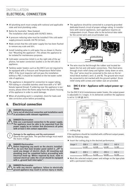
The appliance should be connected to a properly grounded<br />
dedicated branch circuit of proper voltage rating. In installations<br />
with several appliances, each appliance requires an<br />
independent circuit. Please refer to the technical data table<br />
for the correct wire and circuit breaker size.<br />
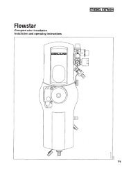
The wire must be fed through the rubber seal located between<br />
the hot and cold water connections. Then feed wires<br />
through strain relief clamp and tighten clamp down on wire.<br />
The „live“ wires must be connected to the slots on the terminal<br />
block marked L and L (L and N). The ground wire must<br />
be connected to slot marked with the ground symbol. Strain<br />
relief clamp with screws and rubber seal are provided.<br />
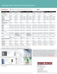
6.1 DHC-E 8/10 - Appliance with output power options<br />
For the DHC-E 8/10 instantaneous water heater, the output power<br />
is adjustable in 2 stages. In its delivered condition the appliance<br />
is set to 7.2 kW @ 240 V.<br />
26_02_02_1084<br />
6. Electrical connection<br />
DANGER Electrocution<br />
Carry out all electrical connection and installation work<br />
in accordance with relevant regulations.<br />
!<br />
DANGER Electrocution<br />
Only use a permanent connection to the power supply.<br />
The appliance must be able to be separated from the<br />
power supply by an isolator that disconnects all poles<br />
with at least 3 mm contact separation.<br />
Damage to the appliance and the environment<br />
Observe the type plate. The specified voltage must match<br />
the mains voltage.<br />
DANGER Electrocution<br />
Before beginning any work on the electric installation,<br />
be sure that main breaker panel switch is „off“ to<br />
avoid any danger of electric shock. All mounting and<br />
plumbing must be completed before proceeding with<br />
electrical hook-up. Where required by local, state or<br />
national electrical codes the circuit should be equipped<br />
with a „ground fault interrupter“.<br />
DANGER Electrocution<br />
As with any electric appliance. failure to electrically<br />
ground appliance may result in serious injury or death.<br />
1 coding plug<br />
If the appliance should be installed with a different output power,<br />
take the following steps:<br />
Insert the coding plug to the desired performance.<br />
Stage 1 208 V 220 V 230 V 240 V<br />
5,4 kW 6,0 kW 6,6 kW 7,2 kW<br />
Stage 2 208 V 220 V 230 V 240 V<br />
7,2 kW 8,1 kW 8,8 kW 9,6 kW<br />
Mark the selected output power and voltage on the type plate<br />
with a permanent marker.<br />
1<br />
26_02_02_1088<br />
6 | DHC-E WWW.STIEBEL-ELTRON-USA.COM