choke manifolds pour tests de puits - FCE
choke manifolds pour tests de puits - FCE
choke manifolds pour tests de puits - FCE

Create successful ePaper yourself
Turn your PDF publications into a flip-book with our unique Google optimized e-Paper software.
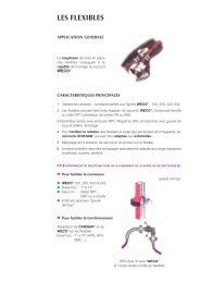
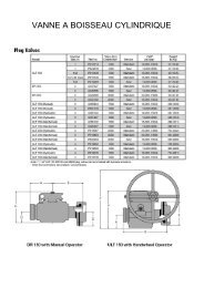
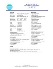
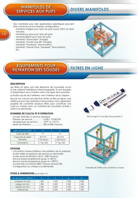
MANIFOLDS DESERVICES AUX PUITSDIVERS MANIFOLDS14Des <strong>manifolds</strong> <strong>pour</strong> <strong>de</strong>s applications spécifiques peuventêtre construits suivant diverses configurations :- Manifold Intégré <strong>pour</strong> <strong>tests</strong> <strong>de</strong> <strong>puits</strong> (avec ESDV et datahea<strong>de</strong>r).- Manifold by-pass <strong>pour</strong> <strong>tests</strong> <strong>de</strong> <strong>puits</strong>.- Manifold BS&W <strong>pour</strong> <strong>tests</strong> <strong>de</strong> <strong>puits</strong>.- Manifold ”Stand pipe” (forage).- Manifold ”Choke and Kill” (forage).- Manifold ”Flowback” (fracturation).- Manifold ”Gravel Pack / Squeeze” (fracturation).- Etc.EQUIPEMENTS POURFILTRATION DES SOLIDESFILTRES EN LIGNEDESCRIPTIONLes filtres en ligne sont <strong>de</strong>s éléments <strong>de</strong> tuyauterie munisd’une crépine métallique interchangeable. Ils sont équipésd’adaptateurs <strong>pour</strong> insertion dans une ligne <strong>de</strong> tuyauterie.Le flui<strong>de</strong> circule <strong>de</strong> l’extérieur vers l’intérieur <strong>de</strong> la crépine.De par son volume <strong>de</strong> rétention limité, le filtre en ligne n’estutilisé que <strong>pour</strong> <strong>de</strong>s opérations temporaires. Il est cependantpossible <strong>de</strong> combiner plusieurs filtres <strong>pour</strong> constituer uneunité sur châssis avec un manifold <strong>de</strong> circulation entrée /sortie à la <strong>de</strong>man<strong>de</strong>.DONNEES DE CALCUL ET D’OPERATION- Suivant ANSI B31.3, Service standard.- Pression <strong>de</strong> service................ : 5 000 / 10 000 PSI.- Température <strong>de</strong> service....... : -29°C à +121°C.- Seuils <strong>de</strong> Filtration.................. : 300 et 800 microns.Filtre en ligne 3” <strong>pour</strong> ligne <strong>de</strong> tuyauterie 2”Ligne <strong>de</strong> tuyauterie 2” 3”Corps <strong>de</strong> filtre 3” 4”Capacité <strong>de</strong> débit(liqui<strong>de</strong>s)20 m 3 /h 42 m 3 /h3 100 bbl/d 6 000 bbl/dConnexions 2” Fig.1502 3” Fig.1502OPTIONS- Circulation inverse (intérieur vers extérieur <strong>de</strong> la crépine).- Autres tailles et pressions <strong>de</strong> service sur <strong>de</strong>man<strong>de</strong>.- Autres seuils <strong>de</strong> filtration (50 à 1 000 microns).- Service basse température (jusqu’à -40°C).- Service haute température (jusqu’à +190°C).- Conformité à la NACE MR01-75 <strong>pour</strong> service H2S.- Configuration sur châssis à la <strong>de</strong>man<strong>de</strong>.Ensemble <strong>de</strong> 2 filtres avec manifold sur chassisPOIDS & DIMENSIONS (<strong>pour</strong> ligne 3”)No. <strong>de</strong> corps 4” (vertical) 2 4 6 8Longueur en mm 1 600 1 600 2 300 3 200Largeur en mm 1 800 2 400 2 400 2 400Hauteur en mm 2 500 2 500 2 500 2 500Poids en kg 2 500 3 500 5 000 7 000