XA 1202 - Multimetrix
XA 1202 - Multimetrix
XA 1202 - Multimetrix
- No tags were found...

Create successful ePaper yourself
Turn your PDF publications into a flip-book with our unique Google optimized e-Paper software.
<strong>XA</strong> <strong>1202</strong>Alimentation multiple5 V, 1 AMultiple Power Supply5 V, 1 ANottiice de ffoncttiionnementtUserr’’s manuallGroupe CHAUVIN ARNOUX190, rue ChampionnetF - 75018 - PARISTél. +33 (0)1.44.85.44.85 - Fax +33 (0)1.46.27.73.89691088B00 - Ed. 1 - 12/10
FrançaisInstructions généralesIntroductionVous venez d'acquérir une alimentation multiple ; cet appareilappartient à la gamme MULTIMETRIX. Nous vous remercions de votreconfiance.Il est conforme à la norme de sécurité EN 61010-1, 2001, relative auxinstruments de mesures électroniques. Vous devez respecter, pourvotre propre sécurité et celle de l'appareil, les consignes décrites danscette notice, dont le contenu ne peut être reproduit sous quelque formeque ce soit sans notre accord.Sécurité Cette alimentation respecte la norme de sécurité EN 61010-1, classe 1,degré de pollution 2. Elle a été conçue pour une utilisation en intérieur,en altitude inférieure à 2000 m, à une température comprise entre 0°Cet 50°C avec une humidité relative < 80 % jusqu’à 4 0°C.Sorties alimentationCatégorie de surtensionTension maximale de sortie50 V CAT I par rapport à la terre15 VDCAlimentation secteurCatégorie de surtensionTension d’alimentationConsommation300 V CAT II110 V ou 230 V ± 10 %; 50-60 Hz< 100 VADéfinition descatégoriesd’installation(cf. CEI 664-1)CAT I :Les circuits de CAT I sont des circuits protégés par desdispositifs limitant les surtensions transitoires à un faibleniveau.Exemple : circuits électroniques protégésCAT II : Les circuits de CAT II sont des circuits d'alimentationd'appareils domestiques ou analogues, pouvant comporterdes surtensions transitoires de valeur moyenne.Exemple : alimentation d'appareils ménagers et d'outillageportableCAT III : Les circuits de CAT III sont des circuits d'alimentationd'appareils de puissance pouvant comporter des surtensionstransitoires importantes.Exemple : alimentation de machines ou appareils industrielsCAT IV : Les circuits de CAT IV sont des circuits pouvant comporterdes surtensions transitoires très importantes.Exemple : arrivées d'énergiePrécautionsAvant l’utilisationL'utilisation de cette alimentation implique de la part de l'utilisateur, lerespect des règles de sécurité habituelles permettant :- de se protéger contre les dangers du courant électrique,- de préserver l’alimentation contre toute fausse manœuvre.Pour votre sécurité, n'utilisez que le cordon livré avec l'appareil. Avantchaque utilisation, veillez à ce qu'il soit en parfait état. Il doit êtrebranché sur le réseau avant de connecter les sorties.2
FrançaisInstructions générales (suite)∗∗∗Toute interruption du conducteur de protection, à l’intérieur ou àl’extérieur de l’instrument, ou débranchement de la borne de terrede protection, risque de rendre l’instrument dangereux.L’interruption intentionnelle est interdite.Lorsque cet instrument doit être alimenté par l’intermédiaire d’unautotransformateur extérieur en vue d’une réduction de la tension,s’assurer que la borne commune est raccordée au neutre (pôle misà la terre) du circuit d’alimentation.La fiche ne doit être introduite que dans une prise munie d’unepièce de contact de mise à la terre. La connexion de sécurité nedoit pas être interrompue par l’utilisation d’une rallonge sansconducteur de protection.Pendant l’utilisation ∗ Lorsque l’ordre de grandeur des paramètres tension et courantsouhaités n’est pas connu, commencez par utiliser les valeursles plus faibles.∗∗∗Avant de débrancher les cordons de liaison du circuit en essai,assurez-vous que l’alimentation est hors tension. Cela évite decréer des extra-courants de rupture ou de fermeture qui, pourde fortes intensités, risquent de faire fondre inutilement lefusible.Ne dépassez jamais une tension totale de sortie de plus de50 V crête par rapport à la terre (mode commun).L’appareil doit être installé dans un endroit ventilé. Veillez à nepas obstruer les trous d’aération.Symboles surl’instrumentAttention : Référez-vous à la notice. Une utilisation incorrectepeut endommager l’appareil et mettre en jeu votre sécurité.ConsignesTerre de protectionSurface chaude∗ Avant toute ouverture de l'appareil, déconnectez-le impérativementde toute source de courant électrique et des circuits de mesure etassurez-vous de ne pas être chargé d'électricité statique, ce quipourrait entraîner la destruction d'éléments internes.∗ Le fusible doit être remplacé par un modèle identique à celuid’origine. Il se situe dans un porte fusible, à l’arrière de l’appareil.∗ Lorsque l'appareil est ouvert, certains condensateurs internespeuvent conserver un potentiel dangereux même après avoirmis l'appareil hors tension.∗ En cas de défauts ou contraintes anormales, mettez l'appareilhors service et empêchez son utilisation jusqu'à ce qu'il soitprocédé à sa vérification.∗ Tout réglage, entretien ou réparation de l’instrument ne doit êtreeffectué que par un personnel qualifié.∗ Une « personne qualifiée » est une personne familière avecl'installation, la construction, l'utilisation et les dangers présentés.Elle est autorisée à mettre en service et hors service l'installationet les équipements, conformément aux règles de sécurité.3
FrançaisInstructions générales (suite)∗ Une « personne qualifiée » est une personne familière avecl'installation, la construction, l'utilisation et les dangers présentés.Elle est autorisée à mettre en service et hors service l'installation etles équipements, conformément aux règles de sécurité.Dispositif desécuritéGarantieVérificationmétrologiqueEntretienRéparationsDéballage etré-emballageLe fusible protège le primaire du transformateur d’alimentation contreles erreurs de tension réseau.Utiliser uniquement un fusible de type : T 4 A / 250 V.Ce matériel est garanti contre tout défaut de matière ou vice defabrication, conformément aux conditions générales de vente.Durant la période de garantie, l'appareil ne peut être réparé que par leconstructeur, celui-ci se réservant la décision de procéder soit à laréparation, soit à l'échange de tout ou partie de l'appareil. En cas deretour du matériel au constructeur, le transport aller est à la charge duclient. La garantie ne s’applique pas suite à :1. une utilisation impropre du matériel ou par association de celui- ciavec un équipement incompatible2. une modification du matériel sans autorisation explicite des servicestechniques du constructeur3. l’intervention effectuée par une personne non agréée par leconstructeur4. l'adaptation à une application particulière, non prévue par ladéfinition du matériel ou par la notice de fonctionnement5. un choc, une chute ou une inondation.Comme tous les appareils de mesure ou d'essais, une vérificationpériodique est nécessaire.Renseignements et coordonnées sur demande :Tél. 02.31.64.51.55 - Fax 02.31.64.51.09.Débranchez l’instrument, puis nettoyez-le avec un chiffon légèrementimbibé d’eau savonneuse ; laissez sécher avant utilisation.N'utilisez jamais de produits abrasifs, ni de solvants.Pour les réparations sous garantie et hors garantie, contactez votreagence commerciale Chauvin Arnoux la plus proche ou votre centretechnique régional Manumesure qui établira un dossier de retour etvous communiquera la procédure à suivre.Coordonnées disponibles sur notre site : http://www.chauvin-arnoux.comou par téléphone aux numéros suivants : 02 31 64 51 55 (centretechnique Manumesure), 01 44 85 44 85 (Chauvin Arnoux).L’ensemble du matériel a été vérifié mécaniquement etélectriquement avant l’expédition.Toutefois, il est conseillé de procéder à une vérification rapide pourdétecter toute détérioration éventuelle lors du transport. Si tel était lecas, faites alors immédiatement les réserves d’usage auprès dutransporteur.En cas de réexpédition, utilisez l’emballage d’origine et indiquez, parune note jointe à l’appareil, les motifs du renvoi.4
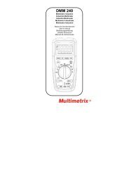
FrançaisDescription de l’appareilPrésentationFace avantCette alimentation à sorties multiples de précision est conçue pourrépondre aux besoins de l’enseignement, des laboratoires et desservices de maintenance.104985 67Organes de commande1. Affichage digital du courant et de la tension en sortie2. LED Indicateur de régulation pour un courant constant (CC)3. LED Indicateur de régulation pour une tension constante (CV)4. Potentiomètre de réglage du courant5. Borne de terre fonctionnelle6. Borne de sortie négative (-)7. Borne de sortie positive (+)8. Interrupteur MARCHE/ARRET9. Potentiomètre de réglage tension « gros »10. Potentiomètre de réglage tension « fin »5
FrançaisDescription FonctionnelleSortie 12 V variableRéglage de la tensionet du courantUtilisation en sourcede courant constantUtilisation en sourcede tension constanteLCD 3 digits (résolution2 ½ digits)Attention• Connectez la charge souhaitée sur la sortie variable.• Sélectionner la polarité de la sortie avec le poussoir (11).• Mettez l’alimentation sous tension.• La tension et le courant s’affichent.• Réglez à l’aide des potentiomètres jusqu’à ce qu’ils atteignent lesvaleurs désirées.• Mettez l’alimentation sous tension.• Bloquez les potentiomètres (9) et (10) en butée droite et le potentiomètre(4) en butée gauche.• Connectez votre charge.• Réglez le potentiomètre (4) jusqu’à la valeur de courant désirée.• Le voyant (2) est allumé et le voyant (3) est éteint.• Positionnez le potentiomètre de réglage de courant (4) sur sa valeurmaximale.• Sélectionner la polarité de la sortie avec le poussoir (11).• Mettez l’alimentation sous tension et régler la tension à l’aide despotentiomètres (9) et (10).• Le voyant (3) est allumé et le voyant (2) est éteint.• Pour régler la limitation de courant : arrêtez l’appareil et courtcircuitezles sorties 5 (+) et 7 (-).• Remettez sous tension et réglez le potentiomètre (4) pour afficher lavaleur du courant limite désiré.• Eteignez l’instrument. Enlevez le court-circuit et branchez la charge.• Remettez sous tension.Pour une meilleure indication de la valeur mesurée, utilisez un appareilde mesure externe.• Cet instrument est très bien protégé. En cas de court-circuit, lecourant en sortie est limité. Des circuits de contrôle limitent lapuissance dissipée pour ne pas endommager l’instrument.Il faut cependant débrancher dès que possible l’appareil et retirer lecourt-circuit.• Stockez l’instrument dans un endroit sec, ventilé et propre.• Débranchez le cordon secteur en cas de non-utilisationprolongée.6
FrançaisCaractéristiquesCaractéristiquestechniquesTension en entréeConsommation110 VAC ± 10 %, 230 VAC ± 10 %, 50 / 60 Hz< 100 VASortie variableSorties fixesTension 0 à 12 V +5 V +15 V –15 VCourant 0 à 500 mA 1 A maxAffichage Tension ± 1 % + 2 digitsCourant ± 2 % + 2 digitsPrécision : 2,5 %Régulation tension ± 0,05 % + 5 mV ± 0,2 % + 5 mVRégulation courant± 0,5 % + 5 mAStabilité, ondulation < 1 mVrms < 5 mVrmsProtectionLimitation de courantCompatibilitéélectromagnétiqueCaractéristiquesgénéralesImmunité EN 55024Emission EN 55022 – EN 61000-3-2 – EN 61000-3-3AffichageRéglagenumérique à LED - 3 digits - Tension et Courant simultanépar potentiomètreSécurité EN 61010-1 (2001) – CAT II 300 V – Pollution 2Dimensions (l h p)Masse170 x 160 x 250 mm≈ 5 kgAccessoires • Notice de fonctionnement• 2 fusibles• Cordon secteur7
EnglishGeneral InstructionsIntroductionThank you for purchasing this MULTIMETRIX multiple power supply.This instrument complies with standard EN 61010-1, 2001,concerning electronic measuring instruments. For your own safety andthat of the instrument, you must comply with the instructions in thismanual. The manual's contents must not be reproduced by any meanswhatever without our prior authorization.Safety This power supply complies with the EN 61010-1 standard, Class 1,pollution degree 2. It is designed for indoor use at altitudes below2000 m and at temperatures from 0 °C to 50 °C, with < 80 % relativehumidity up to 40 °C.Power supply outputsOvervoltage categoryMaximum output voltage50 V CAT I in relation to the earth15 VDCMains power supplyOvervoltage categoryPower supply voltageConsumption300 V CAT II110 V or 230 V ± 10 %; 50-60 Hz< 100 VADefinition ofinstallationcategories(cf. IEC 664-1)CAT I:CAT II:CAT I circuits are circuits protected by systems limitingtransient voltages to a low level.Example: protected electronic circuitsCAT II circuits are the supply circuits of domestic appliancesor similar equipment which may carry medium-level transientovervoltages.Example: power supplies of domestic appliances andportable toolsCAT III: CAT III circuits are power circuits which may carry hightransient overvoltages.Example: power supplies of industrial machinery andequipmentCAT IV: CAT IV circuits are circuits which may carry very hightransient voltages.Example: power feedsPrecautionsBefore useTo use this power supply, users must comply with the customary safetyrules to ensure that:- people are protected against the dangers of electric currents,- the power supply is protected against incorrect operation.For your safety, only use the lead delivered with the instrument. Beforeusing, make sure each time that it is in perfect condition. It must beconnected to the mains network before connecting the outputs.8
EnglishGeneral Instructions (cont'd)During useSymbols on theinstrument∗∗∗∗∗∗∗Any interruption in the protective conductor inside or outside theinstrument and any disconnection of the protective earth terminalmay make the instrument hazardous. Intentional interruption isprohibited.When this instrument needs to be powered via an externalautotransformer to reduce the voltage, make sure that the commonterminal is connected to the neutral (earthed pole) of the powersupply circuit.The plug must only be connected to a socket equipped with anearthing contact. The safety connection must not be interrupted bythe use of an extension lead without a protective conductor.When the level of the required voltage and current parametersis unknown, start by using the lowest values.Before disconnecting the connection leads from the circuit to betested, make sure that the power supply is switched off. Thisavoids the generation of make or break extra-currents whichmay melt the fuse at high current levels.The total output voltage must never exceed 60 Vpeak inrelation to the earth (common mode).The instruments must be set up in a well-ventilated area. Makesure that the ventilation holes are not obstructed.Caution: Refer to the operating manual. Incorrect use maydamage the instrument and threaten your safety.Safety instructionsProtective earthHot surface∗ Before opening the instrument, you must disconnect it from anysource of electric current and from the measurement circuits. Youmust also make sure that you are not electrostatically charged , asit could lead to damage inside the instrument.∗ The fuse must be replaced with a model identical to the originalfuse. It is located in a fuse-holder at the rear of the instrument.∗ Before opening the power supply, you must disconnect the leadsand the mains power cable.∗ When the instrument is open, some of the capacitors inside itmay retain a dangerous potential even after switching off thepower to the instrument.∗ In the event of faults or abnormal stresses, declare theinstrument "out of order" and prevent it from being used until ithas been checked.∗ Any adjustment, maintenance or repair of the instrument must becarried out by qualified personnel.∗ A "qualified person" is a person familiar with the installation, itsdesign, its operation and the hazards present. He/she isauthorized to start up and shut down the installation andequipment, in compliance with the safety rules.9
EnglishGeneral Instructions (cont'd)Safety systemWarrantyMetrologicalverificationCleaningRepairUnpacking andrepackingThe fuse protects the primary of the supply transformer againstnetwork voltage errors.Only use fuses of the following type: T, 4 A / 250 V.This equipment is guaranteed against any material or manufacturingdefects, in accordance with our General Terms of Sale.During the warranty period, the instrument can only be repaired by themanufacturer, who reserves the right to choose either to repair theequipment or to exchange all or part of the instrument. If theequipment is returned to the manufacturer, shipment to themanufacturer's site shall be payable by the customer. The warrantyshall not be applicable in the event of:1. inappropriate use of the instrument or use of the instrument withincompatible equipment2. modification of the equipment without express authorization from themanufacturer's technical department3. maintenance operations carried out by somebody not approved bythe manufacturer4. adaptation for a particular application not covered by the equipmentspecifications or by the operating manual5. shock, fall or flooding.Like all test and measurement instruments, it must be verifiedperiodically.Information and contact details on request:Tel. (33) 2.31.64.51.55 - Fax (33) 2.31.64.51.09.Disconnect the instrument and then clean it with a cloth slightlymoistened with soapy water; leave to dry before using.Never use abrasive products or solvents.For all repairs before or after expiry of warranty, please return thedevice to your distributor.All the equipment has been checked mechanically and electricallybefore shipment.You are nevertheless advised to make a quick check in order todetect any damage that may have occurred during transport. If thereis any damage, contact the carrier immediately to register thecustomer reservations.If returning the product, use the original packaging and accompanythe instrument with a note indicating the reasons for the return.10
EnglishDescription of the InstrumentPresentationFront faceThis high-accuracy multiple-output power supply has beendesigned to meet the needs of the education sector, laboratoriesand maintenance departments.104985 67Control2. Digital display of output current and voltage2. Control LED for constant current (CC)3. Control LED for constant voltage (CV)4. Potentiometer for current adjustment5. Functional earth terminal6. Negative output terminal (-)7. Positive output terminal (+)8. ON / OFF switch9. Potentiometer for "coarse" voltage adjustment10. Potentiometer for "fine" voltage adjustment11
EnglishFunctional DescriptionVariable 12 V outputVoltage and currentadjustmentUse as a constantcurrent sourceUse as a constantvoltage source3-digit LCD (resolution:2 ½ digits)• Connect load to the variable output.• Use the pushbutton (11) to select the output polarity.• Switch on the power supply.• The voltage and current are displayed.• Use the potentiometers to adjust them to the required values.• Switch on the power supply.• Turn potentiometers (9) and (10) as far as they will go to the right andturn potentiometer (4) as far as it will go to the left.• Connect your load.• Adjust the potentiometer (4) to set the required current value.• LED (2) is lit up and LED (3) is switched off.• Set the current potentiometer (4) to the maximum value.• Use the pushbutton (11) to select the output polarity.• Switch on the power supply and adjust the voltage using thepotentiometers (9) and (10).• LED (3) is lit up and (2) is switched off.• To set the current limitation: switch off the instrument and short-circuitoutputs 5 (+) and 7 (-).• Switch the power back on and adjust the potentiometer (4) to displaythe required current limit value.• Switch off the instrument. Remove the short-circuit and connect theload.• Switch the power back on.For a clearer indication of the value measured, use an externalmeasuring instrument.Caution • This instrument is particularly well-protected. In the event of a shortcircuit, the output current is limited. Control circuits limit the powerdissipated in order to prevent damage to the instrument. You shouldnevertheless disconnect the instrument as soon as possible andremove the short-circuit.• Store the instrument in a clean, dry, well-ventilated area.• Disconnect the mains power lead if the instrument is notexpected to be used for a significant period of time.12
EnglishSpecificationsTechnicalspecificationsInput voltageConsumption110 VAC ± 10 %, 230 VAC ± 10 %, 50 / 60 Hz< 100 VAVariable outputFixed outputsVoltage 0 to 12 V +5 V +15 V –15 VCurrent 0 to 500 mA 1 A maxDisplay Voltage ± 1 % + 2 digitsCurrent ± 2 % + 2 digitsAccuracy: 2.5 %Voltage control ± 0.05 % + 5 mV ± 0.2 % + 5 mVCurrent control± 0.5 % + 5 mAStability & ripple < 1 mVrms < 5 mVrmsProtectionCurrent limitationElectromagneticcompatibilityGeneralspecificationsImmunity EN 55024Emission EN 55022 – EN 61000-3-2 – EN 61000-3-3DisplayAdjustmentDigital with LED - 3 digits – Voltage and current simultaneouslyPotentiometerSafety EN 61010-1 (2001) – CAT II 300 V – Pollution 2Dimensions (w h d)Weight170 x 160 x 250 mm≈ 5 kgAccessories • Operating manual• 2 fuses• Mains power cable13