Motorriegel-Schaltgerät 5512-13 Installations und ...
Motorriegel-Schaltgerät 5512-13 Installations und ...
Motorriegel-Schaltgerät 5512-13 Installations und ...

You also want an ePaper? Increase the reach of your titles
YUMPU automatically turns print PDFs into web optimized ePapers that Google loves.
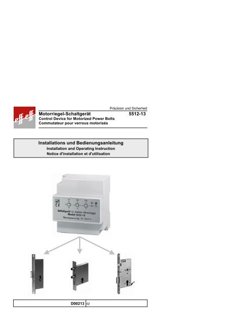
Präzision <strong>und</strong> Sicherheit<br />
<strong>Motorriegel</strong>-<strong>Schaltgerät</strong> <strong>5512</strong>-<strong>13</strong><br />
Control Device for Motorized Power Bolts<br />
Commutateur pour verrous motorisés<br />
<strong>Installations</strong> <strong>und</strong> Bedienungsanleitung<br />
Installation and Operating Instruction<br />
Notice d'installation et d'utilisation<br />
D002<strong>13</strong> 02
Allgemeine Beschreibung<br />
Das <strong>Motorriegel</strong>-<strong>Schaltgerät</strong> <strong>5512</strong>-<strong>13</strong> dient zur Überwachung <strong>und</strong> Steuerung von Türen<br />
mit effeff-Elektro-<strong>Motorriegel</strong>n oder dem effeff-Elektro-Motor-Sicherheitsriegel.<br />
Das <strong>Motorriegel</strong>-<strong>Schaltgerät</strong> <strong>5512</strong>-<strong>13</strong> bietet einen hohen Grad an Funktionalität <strong>und</strong><br />
Einsatzmöglichkeiten, die den meisten Anforderungen gerecht werden.<br />
Der Leistungsumfang umfaßt folgende Punkte:<br />
• Die Elektro-<strong>Motorriegel</strong> der Modellreihen 5511, 5522, 5523, 5525 <strong>und</strong> 5526 können<br />
überwacht <strong>und</strong> gesteuert werden.<br />
• Anschlußmöglichkeit für eine Schaltuhr zur zeitgesteuerten Verriegelung.<br />
• Dauerfreigabe über einen externen Schaltkontakt.<br />
• Kurzzeitentriegelung über einen externen Taster.<br />
• Manuelle Verriegelung über einen externen Taster.<br />
• Die Überwachung des Verriegelungs- bzw. Öffnungszustandes der Tür kann über<br />
die zwei von außen sichtbaren LEDs erfolgen. Weiterhin stehen zwei Ausgänge zur<br />
Verfügung, die zur Ansteuerung externer Geräte verwendet werden können.<br />
• Über drei von außen zugängliche Drehschalter können die Zeiten für die<br />
Kurzzeitentriegelung, die automatische Wiederverriegelung <strong>und</strong> die Motorlaufzeit<br />
eingestellt werden.<br />
• Die Stromversorgung kann durch ein externes Netzteil mit einer<br />
Ausgangsspannung im Bereich von 12-16 V AC/DC erfolgen oder durch eine<br />
Stromversorgung mit einer stabilisierten 12 V Gleichspannung.<br />
• Einfache Montagemöglichkeit, da das Gerät sowohl für die Wand- als auch für die<br />
Hutschienenmontage vorgesehen ist.<br />
Technische Daten:<br />
Eingangsspannung 12 – 16 V AC/DC oder<br />
12 V DC stabilisiert<br />
Stromaufnahme (<strong>Schaltgerät</strong>) typ. <strong>13</strong>0 mA<br />
Stromaufnahme (<strong>Motorriegel</strong>)<br />
5511-65, 5522, 5523 typ. 1,2 A<br />
5525, 5526 typ. 0,3 A<br />
Schutzklasse Schutzkleinspannung<br />
Schutzart nach DIN – 40050 IP 20<br />
Betriebstemperaturbereich 0°C bis +40°C<br />
Lagertemperarturbereich -20°C bis +60°C<br />
Gewicht ca. 190 g<br />
Maße 88 x 98 x 63 mm<br />
Farbe RAL 7035<br />
<strong>Installations</strong>hinweise:<br />
Die Länge der Leitung vom <strong>Motorriegel</strong>-<strong>Schaltgerät</strong> zum Elektro-<strong>Motorriegel</strong> darf<br />
100 m nicht überschreiten. Für Längen bis 40 m ist ein Querschnitt von min. 0,75 mm²<br />
<strong>und</strong> bei Längen bis 100 m ein Querschnitt von min. 1,5 mm² zu verlegen.<br />
Die Länge der Ansteuerleitungen zum <strong>Motorriegel</strong>-<strong>Schaltgerät</strong> ist auf max. 300 m bei<br />
einem Querschnitt von 0,28 mm² begrenzt.<br />
Wir empfehlen die Verwendung abgeschirmter Leitungen, um die Störsicherheit zu<br />
erhöhen. Der Leitungsschirm ist einseitig am PE anzuschließen.
Ansicht des <strong>Motorriegel</strong>-<strong>Schaltgerät</strong>es <strong>5512</strong>-<strong>13</strong><br />
Auswahlschalter für den <strong>Motorriegel</strong>typ:<br />
ON<br />
Schaltereinstellung für die <strong>Motorriegel</strong>typen 5522, 5523 5525 <strong>und</strong> 5526.<br />
ON<br />
Bild 1: Geräteansicht D002<strong>13</strong>-G0000100<br />
1 2 3 4<br />
1 2 3 4<br />
ON<br />
1 2 3 4<br />
Auswahlschalter<br />
für den <strong>Motorriegel</strong>typ<br />
Reset-Stifte:<br />
Bei einer Störung<br />
sind die beiden Sifte<br />
für ca. 1 Sek<strong>und</strong>e<br />
zu brücken<br />
Störungs-LED<br />
S 1 S 2 S 3<br />
Sicherung F2<br />
(1,6 AT)<br />
Sicherung F1<br />
(1,6 AT)<br />
Standard Schaltereinstellung für den Motor-Sicherheitsriegel 5511-65.<br />
Schaltereinstellung für den Motor-Sicherheitsriegel 5511-65 nach den<br />
Anforderungen der (DBP).<br />
S1: Drehschalter zur Einstellung der Kurzzeitentriegelung.<br />
Wird die Tür nach einer Kurzzeitentriegelung nicht geöffnet, erfolgt die automatische<br />
Verriegelung nach Ablauf der eingestellten Zeit. Die Zeit ist einstellbar von 2-30<br />
Sek<strong>und</strong>en im 2 Sek<strong>und</strong>enraster (Beispiel: Stellung 2 entspricht 4 Sek<strong>und</strong>en).<br />
S2: Mit S 2 kann die maximale Motorlaufzeit eingestellt werden.<br />
Im störungsfreien Betrieb schaltet der Motor nach Erreichen der jeweiligen<br />
Endposition automatisch ab. Wird der <strong>Motorriegel</strong> während eines Ent- bzw.<br />
Verriegelungsvorgangs blockiert, schaltet der Motor nach Ablauf der eingestellten<br />
Zeit zum Schutz der Geräte ab.<br />
Die Zeit ist einstellbar von 1-15 Sek<strong>und</strong>en im 1 Sek<strong>und</strong>enraster (Beispiel: Stellung 2<br />
entspricht 2 Sek<strong>und</strong>en).<br />
Bei den <strong>Motorriegel</strong>typen 5511, 5525 <strong>und</strong> 5526 max. Stellung 5!<br />
Bei den <strong>Motorriegel</strong>typen 5522 <strong>und</strong> 5523 max. Stellung 2!<br />
S3: Automatische Verriegelungsverzögerung.<br />
Wird die Tür nach einer Entriegelung geschlossen, verriegelt der <strong>Motorriegel</strong> die Tür<br />
erst nach Ablauf dieser Zeit. Damit wird erreicht, daß der Riegel erst ausschließt<br />
wenn die Tür sicher geschlossen ist (S5 muß geschlossen sein).<br />
Die Zeit ist einstellbar von 1-15 Sek<strong>und</strong>en im 1 Sek<strong>und</strong>enraster (Beispiel: Stellung 2<br />
entspricht 2 Sek<strong>und</strong>en).<br />
Hinweis: Beim <strong>Motorriegel</strong>typ 5511-65 hat dieser Schalter keine Funktion.
Anschlußplan für die Modelle 5522, 5523, 5525 <strong>und</strong> 5526<br />
ON<br />
1 2 3 4<br />
rot<br />
rosa<br />
grün<br />
gelb<br />
weiß<br />
grau<br />
braun<br />
blau<br />
Elektro-<strong>Motorriegel</strong><br />
5522, 5523,<br />
5525, 5526<br />
<strong>Motorriegel</strong>-<strong>Schaltgerät</strong> <strong>5512</strong>-<strong>13</strong><br />
1 2 3 4 5 6 7 8 9 10 11 12 <strong>13</strong> 14 15 16 17 18 19 20 21 22<br />
S5 S6 S7 S8<br />
Stromversorgung<br />
Bild 2: Anschlußplan für <strong>Motorriegel</strong> D002<strong>13</strong>-A0000101<br />
Klemmenbelegung:<br />
1-8 Anschlußklemmen für den Elektro-<strong>Motorriegel</strong>.<br />
S 5 Anschlußmöglichkeit für einen Schaltkontakt (z.B. Schaltuhr).<br />
Mit dem Schließen des Kontaktes S5 wird die Tür verriegelt. Bei geschlossenem<br />
Kontakt S5 kann die Tür mit dem Taster S7 kurzzeitentriegelt werden. Ist der<br />
Kontakt S5 nicht angeschlossen bzw. geöffnet, ist die Tür entriegelt. Die Tür kann<br />
dann mit den Tastern S7 <strong>und</strong> S8 manuell dauerentriegelt bzw. verriegelt werden.<br />
Die Ansteuerung muß durch potentialfreie Kontakte erfolgen.<br />
S 6 Achtung unbedingt erforderlich<br />
Ein in der Türzarge einzubauender Türkontakt (Kegelkontakt). Mit diesem Kontakt<br />
wird der Öffnungszustand der Tür überwacht. Ein Ausschließen des Riegels <strong>und</strong><br />
damit ein Verriegeln ist nur bei geschlossener Tür möglich (S6 geschlossen).<br />
S 7 Taster zur manuellen Kurzzeit- oder Dauerentriegelung (abhängig von S5):<br />
Die Ansteuerung muß durch einen potentialfreien Kontakt erfolgen.<br />
S 8 Taster zur manuellen Verriegelung:<br />
Die Ansteuerung muß durch einen potentialfreien Kontakt erfolgen.<br />
‘ Anschlußmöglichkeit für eine externe Überwachungsanzeige:<br />
Die Klemme 17 führt 12 V, wenn die Tür geschlossen <strong>und</strong> die Klemme 18 wenn die<br />
Tür geöffnet ist. Die maximale Belastbarkeit der Ausgänge beträgt 100 mA.<br />
’ Anschlußmöglichkeit einer Stromversorgung (Klemmen 19 <strong>und</strong> 20):<br />
Die Stromversorgung muß eine Spannung in einem Bereich von 12-16 V AC/DC<br />
liefern <strong>und</strong>, wenn die <strong>Motorriegel</strong>typen 5522, 5523 verwendet werden, mit 1,5 A<br />
belastbar sein. Wir empfehlen das Modell 1001-121.<br />
“ Anschlußmöglichkeit einer Stromversorgung (Klemmen 21 <strong>und</strong> 22):<br />
Die Stromversorgung muß eine stabilisierte 12 V Gleichspannung liefern <strong>und</strong> mit<br />
1,5 A belastbar sein. Pluspol an Klemme 21, Minuspol an Klemme 22.<br />
Zu ’ <strong>und</strong> “: Es darf nur eine Stromversorgung angeschlossen werden!!!<br />
Auf richtigen Anschluß ist zu achten! Bei falschem Anschluß keine Garantieleistung.<br />
2 x 750 Ohm<br />
rt gn<br />
12-16 V AC/DC<br />
z.B. Modell 1001-121<br />
12 VDC stabilisiert<br />
z.B. Notstrom-<br />
versorgung Modell<br />
1006-12020
Anschlußplan für das Modell 5511-65<br />
ON<br />
1 2 3 4<br />
blau<br />
weiß<br />
grau<br />
grün<br />
rot<br />
rosa<br />
braun<br />
Elektro-Sicherheitsriegel<br />
5511-65<br />
<strong>Motorriegel</strong>-<strong>Schaltgerät</strong> <strong>5512</strong>-<strong>13</strong><br />
1 2 3 4 5 6 7 8 9 10 11 12 <strong>13</strong> 14 15 16 17 18 19 20 21 22<br />
gelb<br />
S5<br />
S6 S7<br />
Stromversorgung<br />
Bild 3: Anschlußplan für den Sicherheitsriegel D002<strong>13</strong>-A0000201<br />
Klemmenbelegung:<br />
1-10 Anschlußklemmen für den Elektro-Sicherheitsriegel.<br />
S 5 Anschlußmöglichkeit für einen Schalter oder eine Schaltuhr z.B. zur<br />
zeitgesteuerten Dauerentriegelung. Ist S5 geschlossen, ist die Tür dauerhaft<br />
entriegelt. Eine Verriegelung durch Öffnen <strong>und</strong> Schließen der Tür erfolgt nicht.<br />
Ist S5 offen, kann die Tür mit dem Taster S7 kurzzeitentriegelt werden. Die<br />
Verriegelung erfolgt nach dem Schließen der Tür automatisch.<br />
Die Ansteuerung muß durch potentialfreie Kontakte erfolgen.<br />
S 6 Achtung unbedingt erforderlich<br />
Ein in der Türzarge einzubauender Türkontakt (Kegelkontakt):<br />
Mit diesem Kontakt wird der Öffnungszustand der Tür überwacht. Ein Ausschließen<br />
des Riegels <strong>und</strong> damit ein Verriegeln ist nur bei geschlossener Tür möglich (S6<br />
geschlossen).<br />
S 7 Taster zur manuellen Kurzzeitentriegelung:<br />
Die Ansteuerung muß durch einen potentialfreien Kontakt erfolgen.<br />
‘ Anschlußmöglichkeit für eine externe Überwachungsanzeige:<br />
Die Klemme 17 führt 12 V, wenn die Tür geschlossen <strong>und</strong> die Klemme 18 wenn die<br />
Tür geöffnet ist. Die maximale Belastbarkeit der Ausgänge beträgt 100 mA.<br />
’ Anschlußmöglichkeit einer Stromversorgung (Klemmen 19 <strong>und</strong> 20):<br />
Die Stromversorgung muß eine Spannung in einem Bereich von 12-16 V AC/DC<br />
liefern <strong>und</strong> mit 1,5 A belastbar sein. Wir empfehlen das Modell 1001-121.<br />
“ Anschlußmöglichkeit einer Stromversorgung (Klemmen 21 <strong>und</strong> 22):<br />
Die Stromversorgung muß eine stabilisierte 12 V Gleichspannung liefern <strong>und</strong> mit<br />
1,5 A belastbar sein. Pluspol an Klemme 21, Minuspol an Klemme 22.<br />
Zu ’ <strong>und</strong> “: Es darf nur eine Stromversorgung angeschlossen werden!!!<br />
Auf richtigen Anschluß ist zu achten! Bei falschem Anschluß keine Garantieleistung.<br />
2 x 750 Ohm<br />
rt gn<br />
12-16 V AC/DC<br />
z.B. Modell 1001-121<br />
12 VDC stabilisiert<br />
z.B. Notstrom-<br />
versorgung Modell<br />
1006-12020
General description<br />
The control device for motorized power bolts model <strong>5512</strong>-<strong>13</strong> is suitable for monitoring<br />
and controlling doors equipped with effeff motorized power bolts or the effeff electric<br />
security bolt.<br />
The control device model <strong>5512</strong>-<strong>13</strong> offers a wide range of functions and numerous<br />
possibilities of use corresponding to almost any requirements.<br />
The functions are as follows:<br />
• The motorized power bolts of model series 5511, 5522, 5523 5525 and 5526 can be<br />
monitored and controlled.<br />
• A timer can be connected for time-related locking.<br />
• Permanent unlocking by an external switching contact.<br />
• Momentary unlocking by an external push button.<br />
• Manual locking by an external push button.<br />
• The monitoring of the state of the door – locked/unlocked or open/closed – can be<br />
effected by means of two LEDs visible from outside. Furthermore, two outputs for<br />
triggering external devices are available.<br />
• The periods for momentary unlocking, the automatic relocking and the operating<br />
time of the motor can be set by means of three rotary switches accessible from<br />
outside.<br />
• The power supply can be effected by an external supply unit with an output voltage<br />
of 12-16 V AC/DC or by power supply with stabilized 12 V DC.<br />
• The device can be installed easily as it is suitable for mounting at walls as well as at<br />
top hat rails.<br />
Technical data:<br />
supply voltage 12 – 16 V AC/DC or<br />
12 V stabilized DC<br />
current consumption (control device) typ. <strong>13</strong>0 mA<br />
current consumption (motorized power bolt)<br />
5511-65, 5522, 5523 typ. 1.2 A<br />
5525, 5526 typ. 0.3 A<br />
protection class protective low voltage<br />
environmental class according to DIN – 40050 IP 20 (indoor use)<br />
operating temperature range 0°C to +40°C<br />
storage temperature range -20°C to +60°C<br />
weight approx. 190 g<br />
dimensions 88 x 98 x 63 mm<br />
colour RAL 7035<br />
Installation:<br />
The length of the wires between control device and motorized power bolt must not<br />
exceed 100 m. For lengths of up to 40 m a minimum cross section of 0.75 mm² is<br />
required and for lengths of up to 100 m a minimum cross section of 1.5 mm² is required.<br />
The length of the triggering wires to the control device is limited to a maximum of 300 m<br />
in case the cross section is 0.28 mm².<br />
We recommend to use shielded wires in order to increase the immunity to interfering.<br />
The wire shield must be connected one-sided to the gro<strong>und</strong>.
View of the control device for motorized power bolts model <strong>5512</strong>-<strong>13</strong><br />
Switch for selecting the motorized power bolt type:<br />
ON<br />
Switch position for the motorized power bolt types 5522, 5523 5525 <strong>und</strong> 5526.<br />
ON<br />
illustration 1: View of the device D002<strong>13</strong>-G0000200<br />
1 2 3 4<br />
1 2 3 4<br />
ON<br />
1 2 3 4<br />
switch for selecting the<br />
motorized power bolt type<br />
Reset-pins:<br />
In case of malfunktion<br />
both pins must be bridged<br />
for approx. 1 second<br />
malfunktion-LED<br />
S 1 S 2 S 3<br />
fuse F2<br />
(1,6 AT)<br />
fuse F1<br />
(1,6 AT)<br />
Standard switch position for the electric security bolt type 5511-65.<br />
Switch position for the electric security bolt type 5511-65 according to the<br />
demands of the (DBP).<br />
S1: Rotary switch for setting momentary unlocking period.<br />
If the door is not opened after momentary unlocking, it is automatically relocked after<br />
expiry of the period set. Periods of 2-30 seconds can be set in steps of 2 seconds<br />
(example: setting 2 means 4 seconds).<br />
S2: S2 offers the possibility to set the maximum operating time of the motor.<br />
Provided no malfunctions occur the motor is switched off automatically as soon as<br />
the respective final position is reached. If the motorized power bolt is blocked during<br />
the process of locking or unlocking the motor is automatically switched off after<br />
expiry of the period set in order to protect the devices.<br />
Periods of 1-15 seconds can be set in steps of 1 second (example: setting 2 means<br />
2 seconds).<br />
Motorized power bolt models 5511, 5525 and 5526: max. setting 5!<br />
Motorized power bolt models 5522 and 5523: max. setting 2!<br />
S3: Automatic locking delay.<br />
After unlocking and closing the door the motorized power bolt only effects locking<br />
after expiry of the period set. Consequently, the bolt only throws when the door is<br />
securely closed (S5 must be closed).<br />
Periods of 1-15 seconds can be set in steps of 1 second (example: setting 2 means<br />
2 seconds).<br />
Note: Regarding electric security bolt type 5511-65 this switch has no function.
Connecting diagram for models 5522, 5523, 5525 <strong>und</strong> 5526<br />
ON<br />
1 2 3 4<br />
red<br />
pink<br />
green<br />
yellow<br />
white<br />
grey<br />
brown<br />
blue<br />
Control Device for Motorized Power bolts <strong>5512</strong>-<strong>13</strong><br />
1 2 3 4 5 6 7 8 9 10 11 12 <strong>13</strong> 14 15 16 17 18 19 20 21 22<br />
S5 S6 S7 S8<br />
Electro power bolt<br />
5522, 5523,<br />
5525, 5526<br />
power supply<br />
illustration 2: Connecting diagram for motorized power bolt D002<strong>13</strong>-A0000301<br />
Terminal assignment:<br />
1-8 terminals for motorized power bolt.<br />
S 5 Possibility to connect a switching contact (e. g. timer). The door is locked when<br />
contact S5 is closed. If contact S5 is closed the door can be momentarily unlocked<br />
by operating push button S7. If contact S5 is not connected or open the door is<br />
unlocked. In this case the door can be permanently unlocked or locked manually by<br />
means of push buttons S7 and S8. Triggering must be effected by means of<br />
potential-free contacts.<br />
S 6 Attention: Indispensable<br />
A door contact which must be installed in the door frame (cone contact). This<br />
contact is used for monitoring the state of the door (open/closed). Throwing of the<br />
bolt and consequently locking is only possible when the door is closed<br />
(S6 closed).<br />
S 7 Push button for manual momentary unlocking:<br />
Triggering must be effected by means of a potential-free contact.<br />
S 8 Push button for manual locking:<br />
Triggering must be effected by means of a potential-free contact.<br />
‘ Possibility to connect an external monitoring display system:<br />
Terminal 17 conducts 12 V when the door is closed, terminal 18 conducts 12 V<br />
when the door is open. The maximum capacity of the outputs is 100 mA.<br />
’ Possibility to connect a power supply unit (terminals 19 and 20):<br />
The voltage range to be supplied by the power supply unit is 12-16 V AC/DC and<br />
the unit must provide a capacity of 1.5 A in case motorized power bolt models<br />
5522, 5523 are used. We recommend model 1001-121.<br />
“ Possibility to connect power supply unit (terminals 21 and 22):<br />
The power supply unit must supply 12 V stabilized DC and provide a capacity of<br />
1.5 A. Positive pole to terminal 21, negative pole to terminal 22.<br />
To ’ and “: Only one power supply unit must be connected!<br />
Instructions on wiring and installation must be observed precisecly! Otherwise guarantee will become invalid.<br />
2 x 750 Ohm<br />
rt gn<br />
12-16 V AC/DC<br />
e.g. model 1001-121<br />
12 VDC stabilized<br />
e.g. emergency power<br />
supply unit model<br />
1006-12020
Connecting diagram for models 5511-65<br />
ON<br />
1 2 3 4<br />
blue<br />
white<br />
grey<br />
green<br />
red<br />
pink<br />
brown<br />
Elektric security bolt<br />
5511-65<br />
Control Device for Motorized Power bolts <strong>5512</strong>-<strong>13</strong><br />
1 2 3 4 5 6 7 8 9 10 11 12 <strong>13</strong> 14 15 16 17 18 19 20 21 22<br />
yellow<br />
S5<br />
S6 S7<br />
illustration 3: Connecting diagram for electric security bolt D002<strong>13</strong>-A0000401<br />
Terminal assignment:<br />
1-10 terminals for electric security bolt.<br />
S 5 Possibility to connect a switch or a timer, e. g. for time-related permanent<br />
unlocking. If S5 is closed the door is permanently unlocked. Locking is not effected<br />
by opening or closing the door.<br />
If S5 is open the door can be momentarily unlocked by operating push button S7.<br />
The door is automatically locked after closing the door.<br />
Triggering must be effected by means of potential-free contacts.<br />
S 6 Attention: Indispensable!<br />
A door contact which must be installed in the door frame (cone contact):<br />
This contact is used for monitoring the state of the door (open/closed). Throwing of<br />
the bolt and consequently locking is only possible when the door is closed<br />
(S6 closed).<br />
S 7 Push button for manual momentary unlocking:<br />
Triggering must be effected by means of a potential-free contact.<br />
‘ Possibility to connect an external monitoring display system:<br />
Terminal 17 conducts 12 V when the door is closed, terminal 18 conducts 12 V<br />
when the door is open. The maximum capacity of the outputs is 100 mA.<br />
’ Possibility to connect a power supply unit (terminals 19 and 20):<br />
The voltage range to be supplied by the power supply unit is 12-16 V AC/DC and<br />
the unit must provide a capacity of 1.5 A. We recommend model 1001-121.<br />
“ Possibility to connect power supply unit (terminals 21 and 22):<br />
The power supply unit must supply 12 V stabilized DC and provide a capacity of<br />
1.5 A. Positive pole to terminal 21, negative pole to terminal 22.<br />
To ’ and “: Only one power supply unit must be connected!<br />
Instructions on wiring and installation must be observed precisecly! Otherwise guarantee will become invalid.<br />
2 x 750 Ohm<br />
rt gn<br />
12-16 V AC/DC<br />
e.g. model 1001-121<br />
12 VDC stabilized<br />
e.g. emergency power<br />
supply unit model<br />
1006-12020<br />
power supply
Description générale<br />
Le commutateur <strong>5512</strong>-<strong>13</strong> est nécessaire pour le contrôle et la commande de portes<br />
équipées de verrous motorisés effeff ou de verrous de sécurité effeff.<br />
Par ses caractéristiques et ses fonctionnalités, le commutateur <strong>5512</strong>-<strong>13</strong> répond aux<br />
différents points suivants :<br />
• les verrous motorisés de la série 5511, 5522, 5523, 5525, et 5526 peuvent être<br />
contrôlés et pilotés.<br />
• possibilité de raccordement sur horloge pour programmer un déverrouillage<br />
temporisé.<br />
• déverrouillage permanent par commutateur.<br />
• déverrouillage momentané par bouton-poussoir.<br />
• verrouillage manuel par bouton-poussoir.<br />
• contrôle de l'état verrouillé ou déverrouillé de la porte à l'aide des 2 LED. Une sortie<br />
bornier est prévue pour le report de signalisation.<br />
• temporisation réglable accessible par 3 potentiomètres.<br />
• temporisation à la demande de déverrouillage, reverrouillage après fermeture de la<br />
porte, temporisation de mise en arrêt moteur.<br />
• montage par module sur rail DIN ou en applique sur un mur.<br />
Caractéristiques techniques:<br />
Alimentation 12 – 16 V CC/CA oder<br />
12 V stabilisé<br />
Consommation <strong>5512</strong>-<strong>13</strong> typ. <strong>13</strong>0 mA<br />
Consommation 5511-65, 5522, 5523 typ. 1,2 A<br />
5525, 5526 typ. 0,3 A<br />
Indice d'isolation Isolation courant faible<br />
Indice de protection d'après DIN – 40050 IP 20<br />
Température de fonctionnement 0°C bis +40°C<br />
Température de stockage -20°C bis +60°C<br />
Poids ca. 190 g<br />
Dimensions 88 x 98 x 63 mm<br />
Coloris RAL 7035<br />
Conseils pour la pose:<br />
La longueur du câble de raccordement entre le verrou à moteur électrique et le<br />
commutateur ne doit pas dépasser 100 m.<br />
Il convient d'utiliser du câble de section 0,75 mm 2 pour une longueur de 40 m et du câble<br />
de section 1,5 mm 2 pour une longueur de 40 à 100 m.<br />
La longueur du câble de raccordement entre le commutateur et l'organe de commande<br />
ne doit pas dépasser 300 m avec une section de câble de 0,28 mm 2 .<br />
Nous conseillons d'utiliser un câble avec écran pour protection contre les parasites.<br />
L'écran doit être raccordé à la terre, à une extrémité.
Vue de la platine du commutateur <strong>5512</strong>-<strong>13</strong><br />
Commutateur sélectif pour sélection du type de verrou motorisé :<br />
ON<br />
Position des commutateurs pour verrous : 5522, 5523, 5525 et 5526<br />
ON<br />
Image 1: vue du commutateur D002<strong>13</strong>-G0000300<br />
1 2 3 4<br />
1 2 3 4<br />
ON<br />
1 2 3 4<br />
Commutateur sélectif<br />
des verrous motorisés<br />
Connecteur RESET:<br />
Ponter brièvement les<br />
2 connecteurs. La LED<br />
doit s’éteindre<br />
LED dérangement<br />
S 1 S 2 S 3<br />
Position des commutateurs pour verrous : 5511-65<br />
Fusible F2<br />
(1,6 AT)<br />
Fusible F1<br />
(1,6 AT)<br />
Position des commutateurs pour verrou 5511-65 selon les directives de la DBP<br />
(fonction déverrouillage permanent par horloge).<br />
S1: Temporisation de reverrouillage sans ouverture de porte.<br />
Si la porte n'a pas été ouverte après une demande de déverrouillage, elle se<br />
reverrouille après le temps réglé sur S1. Plage de réglage de 2 – 30 secondes par<br />
fraction de 2 secondes.<br />
Exemple: Position 2 correspond à 4 secondes.<br />
S2: Temporisation d'interruption moteur.<br />
Lorsque le pêne est freiné ou bloqué à la sortie ou à la rentrée, l'alimentation du<br />
moteur est coupée après le temps réglé sur S2. Plage de réglage 1 – 15 secondes<br />
par fraction de 1 seconde.<br />
Exemple: Position 2 correspond à 2 secondes.<br />
Pour verrous motorisés 5511, 5525 et 5526 maxi 5 secondes.<br />
Pour verrous motorisés 5522 et 5523 maxi. 2 secondes.<br />
S3: Temporisation de reverrouillage après ouverture de la porte.<br />
Après déverrouillage et refermeture de la porte, le verrou motorisé reverrouille la<br />
porte après le temps réglé sur S3 (si contact S5 est fermé). Plage de réglage 1 – 15<br />
secondes, par fraction de 1 seconde.<br />
Exemple: Position 2 correspond à 2 secondes.<br />
Remarque: La temporisation S3 n'est pas utilisée avec un verrou 5511-65.
Schéma de raccordement pour modèle 5522, 5523, 5525 et 5526<br />
ON<br />
1 2 3 4<br />
rouge<br />
rose<br />
vert<br />
jaune<br />
blanc<br />
gris<br />
brun<br />
bleu<br />
Verrou de sécurité<br />
5522, 5523,<br />
5525, 5526<br />
Commutateur <strong>5512</strong>-<strong>13</strong><br />
1 2 3 4 5 6 7 8 9 10 11 12 <strong>13</strong> 14 15 16 17 18 19 20 21 22<br />
S5 S6 S7 S8<br />
alimentation<br />
Image 2: Schéma de raccordement pour verrous motorisés D002<strong>13</strong>-A0000501<br />
Bornier de raccordement:<br />
1-8 Raccordement du verrou motorisé.<br />
S 5 Raccordement pour contact de commande (ex.: contrôle d'accès, horloge, bouton<br />
poussoir etc...)..<br />
En fermant le contact S5, la porte se verrouille. Avec le contact S5 fermé, la porte<br />
peut-être déverrouillée temporairement par le contact S7. Avec le contact S5 ouvert<br />
ou non branché, la porte est déverrouillée. Avec les contacts S7 et S8, la porte peut<br />
se verrouillée ou déverrouillée en permanence. Les commandes doivent se faire<br />
par contact libre de potentiel.<br />
S 6 Raccordement pour contact de porte obligatoire.<br />
Ce contact de porte est nécessaire, nous recommandons le modèle 10400. Ce<br />
contact autorise la sortie du pêne à la fermeture de la porte (S6 contact fermé).<br />
S 7 Raccordement pour déverrouillage temporisé.<br />
La commande doit se faire par contact libre de potentiel.<br />
S 8 Raccordement pour verrouillage.<br />
La commande doit se faire par contact libre de potentiel.<br />
‘ Possibilité de raccordement pour une signalisation externe.<br />
La borne 17 délivre 12 V lorsque la porte est verrouillée. La borne 18 délivre 12 V<br />
lorsque la porte est déverrouillée. Pouvoir de coupure (17 et 18) 12 V / 100 mA.<br />
’ Possibilité de raccordement pour alimentation (bornes 19 et 20).<br />
L'alimentation doit fournir 12 – 16 V en CA OU CC avec une capacité de 1,5A, nous<br />
recommandons le transformateur réf. 1001-121.<br />
“ Possibilité de raccordement pour alimentation secourue (bornes 21 et 22).<br />
L'alimentation secourue doit fournir 12V en CC, régulée avec une capacité de 1,5A.<br />
Raccorder pôle positif à la borne 21, pôle négatif à la borne 22.<br />
Points ’ et “: sur borne 21-22 raccorder uniquement une alimentation secourue.<br />
Veillez à respecter le raccordement ! En cas de mauvais raccordement, aucune garantie<br />
ne sera valable.<br />
2 x 750 Ohm<br />
rt gn<br />
12-16 V CA/CC<br />
ep.ex. modèle 1001-121<br />
12 VCC stabilisé<br />
p.ex.apparreil d’alimentation<br />
de secours modèle<br />
1006-12020
Schéma de raccordement pour modèle 5511-65<br />
ON<br />
1 2 3 4<br />
bleu<br />
blanc<br />
gris<br />
vert<br />
rouge<br />
rose<br />
brun<br />
Verrou de sécurité<br />
5511-65<br />
Commutateur <strong>5512</strong>-<strong>13</strong><br />
1 2 3 4 5 6 7 8 9 10 11 12 <strong>13</strong> 14 15 16 17 18 19 20 21 22<br />
jaune<br />
S5<br />
S6 S7<br />
alimentation<br />
Image 3: Schéma de raccordement pour verrou de sécurité D002<strong>13</strong>-A0000601<br />
Bornier de raccordement:<br />
1-10 Raccordement du verrou de sécurité 5511-65.<br />
S 5 Raccordement pour contact de commande par exemple, contrôle d'accès, horloge,<br />
bouton-poussoir etc…<br />
Quand le contact S5 est fermé, la porte est déverrouillée en permanence. Le<br />
verrouillage après refermeture de la porte n'est pas actif. Quand le contact S5 est<br />
ouvert, le porte peut être déverrouillée temporairement. Le verrouillage après<br />
refermeture est actif.<br />
S 6 Raccordement pour contact de porte obligatoire. Ce contact de porte est<br />
nécessaire, nous recommandons le modèle 10400. Ce contact autorise la sortie du<br />
pêne à la fermeture de la porte (S6 contact fermé).<br />
S 7 Raccordement pour déverrouillage temporisé.<br />
La commande doit se faire par contact libre de potentiel.<br />
‘ Possibilité de raccordement pour signalisation externe.<br />
La borne 17 délivre 12 V lorsque la porte est verrouillée. La borne 18 délivre 12 V<br />
lorsque la porte est déverrouillée. Pouvoir de coupure (17-18) 12 V/100 mA.<br />
’ Possibilité de raccordement pour alimentation (bornes 19 et 20).<br />
L'alimentation doit fournir 12 – 16 V en CA ou CC avec une capacité de 1,5 A, nous<br />
recommandons le transformateur réf. 1001-121.<br />
“ Possibilité de raccordement pour alimentation secourue (bornes 21 et 22).<br />
L'alimentation secourue doit fournir 12 V en CC régulé avec une capacité de 1,5 A.<br />
Raccorder oôle positif à la borne 21, pôle négatif à la borne 22.<br />
Points ’ et “: sur borne 21-22 raccorder uniquement une alimentation secourue.<br />
Veillez à respecter le raccordement ! En cas de mauvais raccordement, aucune garantie<br />
ne sera valable.<br />
2 x 750 Ohm<br />
rt gn<br />
12-16 V CA/CC<br />
ep.ex. modèle 1001-121<br />
12 VCC stabilisé<br />
p.ex.apparreil d’alimentation<br />
de secours modèle<br />
1006-12020
TÜ V<br />
DINENISO9001<br />
effeff Fritz Fuss GmbH & Co. Telefon (07431) 123-0<br />
Kommanditgesellschaft auf Aktien Telefax (07431) 123-240<br />
Johannes-Mauthe-Str. 14<br />
D-72458 Albstadt<br />
internet: http//www.effeff.com<br />
eMail: infotoe@effeff.com