Bedienungsanleitung - Only Trains
Bedienungsanleitung - Only Trains
Bedienungsanleitung - Only Trains

Create successful ePaper yourself
Turn your PDF publications into a flip-book with our unique Google optimized e-Paper software.
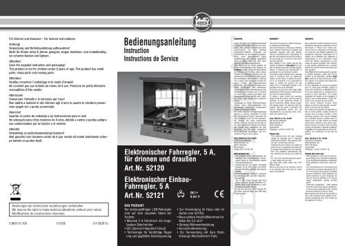
• 50110 oder jedem anderen LGB-Trafo, Wechsel- oder Gleichstrom• Technische Daten:52120 Grundfläche: 175 x 115 mm- 52121 Einbaumaße: 108 x 80 mm,Einbautiefe: 50 mm- Eingangsspannung: 15-18 V -Wechsel spannung oder max. 24 VGleichspannung- Ausgangsspannung: max. 24 VGleichspannung- Ausgangsstrom: max. 5 A Gleich -stromDAS LGB-PROGRAMMZum Einsatz mit diesem Produktschlagen wir folgende LGB-Artikelvor:- 50110 Hochleistungs-Wechselstrom-Trafo,230 V, 24 V, 5 A- 50160 Anschlußkabel für Fahr -stromInformationen über das kompletteLGB-Programm finden Sie im LGB-Katalog.BEDIENUNGEinbauMechanisch52120:Der Fahrregler 52120 kann im Hausoder im Garten aufgestellt werden.52121:Der Einbau-Fahrregler 52121 ist zumEinbau in Stellpulte u. ä. vorgesehen.So bauen Sie den Fahrregler ein:1. Bohren Sie ein Loch (Durch -messer mindestens 6,5 mm) für dieReglerachse. Ziehen Sie den Regler -knopf und die Reglerskala nach obenab.2. Bohren Sie zwei Löcher für dieBefestigungsschrauben. Stecken Sieden Fahrregler von unten durch dieBohrung für die Reglerachse. Be -festigen Sie ihn von oben mit zweiM3-Schrauben.Achtung! Die Schrauben dürfen nichtmehr als 4 mm über die Unterseitedes Kühlblechs herausragen. Wenndie Schrauben weiter hervorstehenoder auf die Platine drücken, wird diePlatine beschädigt.3. Kleben Sie die Reglerskala auf dieVorderseite des Stellpults undstecken Sie den Reglerknopf wiederauf den Fahrregler.Achtung! Das Kühlblech muß belüftetsein. Wenn der Fahrregler ineinem geschlossenen Gehäuse eingebautwird, müssen ausreichendeBelüftungslöcher vorgesehen werden.Werden mehrere Fahrreglernebeneinander eingebaut, muß zwischenden Kühlblechen ein Abstandvon mindestens 5 mm bleiben.ElektrischDer Fahrregler kann mit Wechsel -strom oder Gleichstrom von jedemLGB-Trafo betrieben werden. Eineeingebaute elektronische Schaltungerkennt automatisch den Spann -ungs typ und wandelt diesen zurEinspeisung in die Gleise entsprechendum.Schließen Sie den Trafo an dieAnschlüsse rechts am Fahrregler(mit WS/SW gekennzeichnet) an.Verbinden Sie die Anschlüsse linksam Fahrregler (mit RT/BL gekennzeichnet)mit den Gleisen (Abb. 1).Hinweis: Der Fahrregler 52120 kannauch mit zwei 12-V-Autobatterie verwendetwerden. Aus Sicherheits -gründen müssen Sie dabei eine 4-A-Autosicherung einbauen.Fahrbetrieb auch ohne SteckdoseAbbildung 2: Bei Anschluß an zwei12-Volt-Autobatterien, muß zumSchutz der nachgeschalteten Geräteeine 4-A-Feinsicherung (z.B. Auto-34
Kabel-Sicherung wie bei Autoradiosverwendet) zwischengeschaltet werden.Ohne diese 4-A-Sicherung wirdder Fahrregler zerstört!Achtung! Verwenden Sie zumAnschluß des Fahrreglers Kabel miteinem Querschnitt von mindestens0,5 mm 2 (z. B. LGB 50160).BedienungDer Fahrregler ist ausgeschaltet,wenn der Reglerknopf in der Mitteauf „0“ steht. Drehen Sie denReglerknopf nach rechts oder links,um Geschwindigkeit und Fahrt -richtung zu regeln.Überlast-SicherungDer Fahrregler ist mit einerKurzschluß-Sicherung ausgestattet.Wenn ein Kurzschluß auftritt, schaltetsich der Fahrregler ab. DieKurzschluß-Abschaltung funktioniertjedoch nur, wenn der angeschlosseneTrafo einen Fahrstrom von mindestens5 A liefern kann.Wenn Ihr LGB-Trafo weniger als 5 Aabgibt, wird bei einem Kurzschlußdie Überlast-Sicherung des Trafosausgelöst (siehe Stromversorgung).Achtung! Ziehen Sie bei Überlastungoder Kurzschluß sofort das Netz -kabel des Trafos aus der Steckdose.1. Kurzschluß: Beheben Sie dieUrsache des Kurzschlusses. SteckenSie den Stecker wieder in die Steckdose.Drehen Sie den Reglerknopf etwa 2Sekunden lang auf Stellung „0“, umden Fahrregler wieder einzuschalten.2. Überlastung: Nehmen Sie eineoder mehrere Loks vom Gleis.Stecken Sie den Stecker wieder in dieSteckdose. Drehen Sie den Regler -knopf etwa 2 Sekunden lang aufStellung „0“, um den Fahrregler wiedereinzuschalten.StromversorgungAchtung! Um Sicherheit und Zu -verlässigkeit zu gewährleisten, be -treiben Sie dieses Produkt nur mitLGB-Trafos. Bei Verwendung vonanderen Trafos funktioniert die Überlast-Sicherungunter Umständennicht. Weiterhin wird bei Verwend -ung von anderen Trafos Ihre Garantieungültig.Weitere Informationen über die LGB-Trafos und Fahrregler zur Verwend -ung im Haus oder im Freien und überdas Mehrzugsystem finden Sie imLGB-Katalog.WERKSERVICEBei unsachgemäßer Wartung wirdIhre Garantie ungültig. Um fachgerechteReparaturleistungen zu erhalten,wenden Sie sich an IhrenFachhändler oder an die LGB-Service-Abteilung:Gebr. Märklin & Cie. GmbHLGB Service-AbteilungWitschelstraße 10490431 NürnbergDeutschlandTelefon: (0911) 83707-38Telefax: (0911) 83707 818Die Einsendung erfolgt zu IhrenLasten.VORSICHT! Dieses Produkt ist nichtfür Kinder unter 8 Jahren geeignet.Das Produkt hat kleine, scharfe undbewegliche Teile. Bewahren SieVerpackung und Bedienungsanleit -ung auf.5
Artikel, technische Daten und Liefer -daten können sich ohne Vor -ankündigung ändern. Einige Artikel sindnicht überall und über alle Fachhändlererhältlich. Einige Abbildungen zeigenHandmuster. LGB und Märklin sind eingetrageneMarken der FirmaGebr. Märklin & Cie. GmbH, Göppingen.Andere Marken sind ebenfallsgeschützt.© Gebr. Märklin & Cie. GmbH6
USAGBFor information on the complete LGBprogram, see the LGB catalog.52120Analog Throttle, Indoor/Outdoor52121Analog Throttle, UnmountedTHE PRODUCTThe powerful LGB throttles incorporatestate-of-the-art technology:• 5 amp capacity with built-in AC/DCconversion• SIC (Special Integrated Circuit)technology for electronic• throttle control and a smooth voltagewaveform• For use indoors and outdoors(52120 only)• Safety connectors for wires up to0.5 mm 2• Low heat generation• Short circuit sensor• Use with High-Output AC Trans -former or any LGB power supply,AC or DC• Specifications• 52120: Base dimensions:175 x 115 mm• 52121: Dimensions: 108 mm x 80mm, installation depth: 50 mm• Input voltage: 15-18V AC. or 24VDC max.• Output voltage: 24V DC max.• Output current: 5A DC max.THE PROGRAMWith this product, we recommendthe following items:- 50110 AC Transformer, 230V, 24V,5A- 50111 AC Transformer, 110V, 24V,5A- 50160 Track Power CableOPERATIONInstallationMechanical52120:The 52120 can be installed indoorsor outdoors.52121:The 52121 is designed for installationin control panels or similarapplications. To install the 52121,follow these instructions:1. Drill a hole (diameter at least 6.5mm, 9/32 in) for the axle of the throttleknob. Pull the throttle knob andthe graduated dial face off the unit.2. Drill two holes for the mountingscrews. Insert the axle of the throttleknob from below through the holedrilled in step 1. Use two M3 screwsto secure the throttle from above.Attention! The screws must not protrudemore than 4 mm (3/16“) fromthe heat sink. If they protrude furtheror press on the circuit board, the circuitboard will be damaged.3. Glue the graduated dial face ontothe face of the control panel andpress the throttle knob onto thethrottle.Attention! Make sure the heat sink isventilated. If the throttle is installedin a closed housing, provide adequateventilation holes. Wheninstalling several throttles 52121next to each other, make sure there isa space of at least 5 mm between theheat sinks.ElectricalThe throttles can be connected to ACor DC power from any LGB powersupply. An internal circuit automaticallydetects the power type and con-7
verts it to track power.Connect the power supply to the terminalson the right side of the throttle(marked WS/SW). Connect thetrack to the terminals on the left side(marked RT/BL).Hint: The throttle can also be usedwith two 12 volt automotive or „deepcycle“ battery. For safety, also use aregular automotive fuse rated up to 4amps.Operating without mains voltagesupplyFigure 2: When connecting to a 12-volt car battery, the circuit must beprotected via a 4 A fuse, (e.g. car inleadfuse holder as used for carradios).If a fuse is not fitted, the electroniccontroller will be damaged.Attention! Connect the throttle usingwires with a cross-section of at least0.5 mm 2 (20 AWG) (e. g., LGB50160).OperationWhen the throttle knob is in the center„0“ position, the throttle is off.Turn the throttle left or right tochange the speed and direction ofthe train.Overload ProtectionThe throttle is protected againstshort circuits. If a short circuitoccurs, the throttle will switch off.However, this overload protectionfunctions only when using a powersupply with an output of 5 amps ormore.When using an LGB power supplywith an output of less than 5 amps, ashort circuit will trigger the overloadprotection of your power pack (seePower Supply).Attention! If there is a short circuit oroverload, unplug the power supplyfrom the house current outlet immediately:1. Short circuit: Find and remove theshort circuit. Reconnect the powersupply cord. Reset the throttle byturning the throttle knob to the center„0“ position for at least 2 seconds.2. Overload: Remove one or morelocos from the track. Reconnect thepower supply cord. Reset the throttleby turning the throttle knob to thecenter „0“ position for at least 2 seconds.Power SupplyAttention! For safety and reliability,operate this product with LGB powersupplies (transformers and powerpacks) only. With other power supplies,the overload protection maynot work. The use of non-LGB powersupplies will void your warranty.For more information on LGB powersupplies for indoor, outdoor andmulti-train operation, see the LGBcatalog.FACTORY SERVICEImproper service will void your warranty.For quality service, contactyour authorized retailer or the LGBfactory service station:Gebr. Märklin & Cie. GmbHLGB Service-AbteilungWitschelstraße 10490431 NürnbergDeutschlandTelephone: +49 (911) 83707-38Telefax: +49 (911) 83707 818You are responsible for any shippingcosts, insurance and customs fees.CAUTION! This model is not for childrenunder 8 years of age. This model hassmall parts, sharp parts and moving8
parts. Save the supplied packaging andinstructions.Products, specifications and availabilitydates are subject to changewithout notice. Some products arenot available in all markets and at allretailers. Some products shown arepre-production prototypes. LGB,Märklin logotype Gebr. Märklin & Cie.GmbH. Other trademarks are theproperty of their owners.© Gebr. Märklin & Cie. GmbH9
F52120Commande électronique, 5 A,pour usage à l’intérieur et enplein air52121Commande électronique àmonter, sans boîtier, 5 ALE PRODUITLes commandes électroniques hauteperformance ont été entièrement misà jour :• Courant de traction : 5A max. avecredresseur de courant intégré• Technologie SIC (circuit spécialintégré) pour réglage sensible ettension continue égalisée• Pour usage à l’intérieur ou dans unjardin (seulement 52120)• Nouvelles bornes de raccordementfiables pour câble jusqu’à 0,5 mm 2• Faible dégagement de chaleur• Système de reconnaissance decourt-circuit• Conçu pour être utilisé avec letransformateur à courant alternatifà rendement élevé 50110 ou avectout autre transformateur LGB àcourant alternatif ou continu• Données techniques :52120 : Surface de base : 175 x115 mm52121 : Dimensions : 108 x 80 mm,encastrement : 50 mmTension à l’entrée : 15-18 V tensionalternative ou max. 24 V tensioncontinueTension de sortie : max. 24 V tensioncontinueCourant de sortie : max. 5 A courantcontinuLA GAMME LGBPour l’utilisation de ce produit, nousrecommandons les articles LGB suivants:• 50110 Transformateur à courantalternatif à rendement élevé, 230 V,24 V, 5 A• 50160 Cordon d’alimentation desvoiesVeuillez consulter le catalogue LGBpour de plus amples informationssur l’ensemble de la gamme LGB.COMMANDEMontagemécanique52120:Le dispositif de commande 52120peut être installé à l’intérieur ou dansun réseau de jardin.52121:Le dispositif de commande électroniqueest entre autres conçu pour lemontage dans des pupitres de commande.Ce dispositif est monté de lamanière suivante:1. Percez un trou (diamètre d’aumoins 6,5 mm) pour l’axe de réglage.Otez le bouton de réglage et l’échellede réglage en tirant vers lehaut.2. Percez deux trous pour les vis defixation. Insérez le dispositif de commandepar le bas en le faisant passerpar le trou prévu pour l’axe de réglage.Fixez le par le haut avec deux visM3.Attention ! Les vis ne doivent pasdépasser de plus de 4 mm de la partieinférieure de la tôle de refroidissement.Dans le cas contraire ou sielles appuient sur la platine, celle-cisera endommagée.3. Collez l’échelle de réglage sur lapartie avant du pupitre de commandeet remontez le bouton de réglage sur10
le dispositif de commande.Attention ! La tôle de refroidissementdoit être aérée. Dans le cas oùle dispositif de commande seraitmonté dans un boîtier fermé, prévoirsuffisamment de trous d’aération. Siplusieurs dispositif de commandesont montés les uns à côté des autres,un intervalle d’au moins 5 mmdoit être prévu entre les tôles derefroidissement.MontageélectriqueLe dispositif de commande peut êtreutilisé avec n’importe quel transformateurLGB en courant alternatif oucontinu. Un couplage électroniqueintégré reconnaît automatiquementle type de tension et la convertit encourant continu d’alimentation desrails.Connectez le transformateur aux raccordssitués à droite du poste decommande (indiqués par WS/SW).Reliez les raccords à gauche duposte de commande (indiqués parRT/BL) aux rails.Remarque : Le dispositif de commande52120 peut aussi être utiliséavec un accumulateur de 12 V Dansce cas, il faut pour des raisons desécurité installer un fusible de sécuritéautomatique de 4 A.Service sans prise de courantFigure 2: Si l’on raccorde à une batterieautomobile deux 12 volts, il fautintercaler un fusible en fil fin de 4 A(par exemple, fusible de câble d’auto-radio)pour la protection desappareils branchés. Sans ce fusiblede 4 A, le régulateur sera détruit!Attention ! Pour le raccordement dudispositif de commande, utilisez uncâble d’une coupe transversale d’aumoins 0,5 mm2 (par ex., LGB 50160)CommandeLe dispositif de commande est horsservice lorsque le bouton de réglagese trouve au milieu sur «0». Tournezle bouton de réglage vers la droite oula gauche pour régler la vitesse et lesens de direction de la locomotive.Fusible de surchargeLe dispositif de commande 52120est équipé d’un fusible de court-circuit.En cas de court-circuit, le dispositifde commande s’arrête automatiquement.Le disjoncteur de courtcircuitfonctionne seulement si letransformateur connecté fournit uncourant de traction d’au moins 5 A.En cas contraire, le fusible de surchargedu transformateur est déclenché(voir Alimentation électrique).Attention ! En cas de surcharge oude court-circuit, débranchez immédiatementle câble de distribution dutransformateur de la prise électrique.1. Court-circuit : Eliminez la causedu court-circuit. Rebranchez leconnecteur dans la prise électrique.Tournez le bouton de réglage pendant2 secondes environ sur la position«0» pour remettre le poste decommande en marche.2. Surcharge : Retirez une ou plusieurslocomotives des voies.Rebranchez le connecteur dans laprise électrique. Tournez le boutonde réglage pendant 2 secondes environsur la position «0» pour remettrele dispositif de commande en marche.Alimentation électriqueAttention ! Afin d’assurer un fonctionnementsûr et fiable de ce produit,n’utilisez celui-ci qu’avec destransformateurs LGB. Si vous utilisezdes transformateurs provenant d’au-11
tres fabricants, le fusible de surchargerisque de ne pas fonctionner etvotre garantie peut être annulée.Veuillez consulter le catalogue LGBpour de plus amples informationsconcernant les transformateurs etrégulateurs LGB, pour un emploi à lamaison ou en plein air, ainsi que lesystème multitrain.SERVICE DE L’USINEUn entretien incorrect peut annulervotre garantie. Si un entretien homologuéà l’usine s’avère nécessaire,veuillez vous adresser à votre revendeurspécialisé ou au département deservice après-vente LGB :Gebr. Märklin & Cie. GmbHLGB Service-AbteilungWitschelstraße 10490431 NürnbergDeutschlandTéléphone: +49 (911) 83707-38Telefax: +49 (911) 83707 818Les frais d’expédition sont à votrecharge.ATTENTION ! Ce produit n’est pas pourles enfants au-dessous de 8 ans. Ilcomporte des petites pièces, des partiespointues et des pièces mobiles.Conserver l’emballage et les instructions.Les produits, spécifications et dates dedisponibilité sont sujettes à modificationsans préavis. Certains produitspeuvent ne pas être disponibles surcertains marchés et chez tous lesdétaillants. Certains produits illustréssont des prototypes de pré-série. LGB,Märklin sont des marques déposées deGebr. Märklin & Cie. GmbH, Allemagne.Les autres marques de commerce sontla propriété de leurs détenteurs respectifs.© Gebr. Märklin & Cie. GmbH12