RDH D-3 - Nicotra Gebhardt
RDH D-3 - Nicotra Gebhardt
RDH D-3 - Nicotra Gebhardt

You also want an ePaper? Increase the reach of your titles
YUMPU automatically turns print PDFs into web optimized ePapers that Google loves.
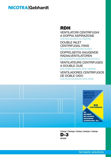
<strong>RDH</strong><br />
VENTILATORI CENTRIFUGHI<br />
A DOPPIA ASPIRAZIONE<br />
CON PALE INCLINATE ALL‘INDIETRO<br />
DOUBLE INLET<br />
CENTRIFUGAL FANS<br />
WITH BACKWARD INCLINED BLADES<br />
DOPPELSEITIG SAUGENDE<br />
RADIALVENTILATOREN<br />
MIT RÜCKWÄRTS GEKRÜMMTEN SCHAUFELN<br />
VENTILATEURS CENTRIFUGES<br />
A DOUBLE OUIE<br />
AVEC AUBES INCLINÉES VERS L‘ARRIÈRE<br />
VENTILADORES CENTRIFUGOS<br />
DE DOBLE OIDO<br />
CON PALAS INCLINADAS HACIA ATRAS<br />
Catalogo | Catalogue | Katalog | Catalogue | Catalogo:<br />
D-3<br />
08/2009<br />
1
<strong>Nicotra</strong> <strong>Gebhardt</strong> worldwide<br />
SPAIN<br />
Ctra. Alcalá-Villar del Olmo, Km. 2,830<br />
28810 Villalbilla-Madrid<br />
Phone +34-918846110<br />
Fax +34-918859450<br />
E-mail info@nicotra.es<br />
c/.Coso, 67-75, esc. 1.a,1.oB<br />
50001 Zaragoza<br />
Phone 00 34-976-290550<br />
Fax 00 34-976-298127<br />
E-mail gebhardt@teleline.es<br />
BELGIUM<br />
Haeghensgoed, 13 - 00/01<br />
9270 Laarne<br />
Phone +32 (0) 9/336.00.01<br />
Fax +32 (0) 9/336.00.05<br />
E-mail info.nicotra@nicotra.be<br />
FRANCE<br />
8 chemin des Mûriers BP 324<br />
69745 Genas cedex.<br />
Phone 00 33 (0) 472790120<br />
Fax 00 33 (0) 472790121<br />
E-mail nicotra.france@wanadoo.fr<br />
SWEDEN<br />
Box 237<br />
Kraketorpsgatan 30<br />
43123 Mölndal<br />
Phone 00 46-31-874540<br />
Fax 00 46-31-878590<br />
E-mail goteborg@gebhardt.se<br />
GREAT BRITAIN<br />
Unit D, Rail Mill Way<br />
Parkgate Business Park<br />
Rotherham<br />
South Yorkshire<br />
S62 6JQ<br />
Phone +044-01709-780760<br />
Fax +044-01709-780762<br />
E-mail sales@nicotra.co.uk<br />
Monarch House<br />
1-7 Smyth Road<br />
Bedminster<br />
Bristol<br />
Phone +44 (0)870 043 5207<br />
Fax +44 (0)870 043 5212<br />
E-mail info@kiloheat.co.uk<br />
http://www.kiloheat.co.uk/<br />
MALAYSIA<br />
Lot 1799, Jalan Balakong<br />
Taman Perindustrian Bukit Belimbing<br />
43300 Seri Kembangan<br />
Selangor<br />
Phone +603-89612588<br />
Fax +603-89618337<br />
E-mail nicotra@tm.net.my<br />
Lot 1799, Bukit Belimbing Industrial Area<br />
Jalan Balakong<br />
43300 Seri Kembangan<br />
Selangor Darul Ehsan<br />
Phone +603 8961 2588<br />
Fax +603 8961 8337<br />
E-mail info@gebhardt-singapore.com<br />
THAILAND<br />
6/29 Soi Suksawadi 2, Moo 4, Suksawadi Road,<br />
Kwang Jomthong, Khet Jomthong,<br />
Bangkok 10150<br />
Phone +662 476 1823-6<br />
Fax +662 476 1827<br />
E-mail sales@nicotra.co.th<br />
SINGAPORE<br />
No. 15 West Coast Highway<br />
# 04-08 Pasir Panjang Building<br />
Singapore 117861<br />
Phone (065) 6265 1522<br />
Fax (065) 6265 2400<br />
E-mail info@gebhardt-singapore.com<br />
<strong>Nicotra</strong> <strong>Gebhardt</strong> GmbH<br />
<strong>Gebhardt</strong>strasse 19-25<br />
74638 Waldenburg, Germany<br />
Phone +49 (0)7942 101 0<br />
Fax +49 (0)7942 101 170<br />
E-mail info@gebhardt.de<br />
www.nicotra-gebhardt.com<br />
AUSTRALIA<br />
47 Jesica Road,<br />
Campbellfield, VIC 3061<br />
Phone +613-9357-7464<br />
Fax +613-9357-8700<br />
E-mail info@nicotra.com.au<br />
INDIA<br />
Plot no 28f, Sector-31<br />
Kasna, Greater Noida-201308<br />
U.P. INDIA<br />
Phone +91-0120-4203400<br />
Fax +91-0120-4203401<br />
E-mail sales@nicotraindia.com<br />
CHINA<br />
88 Tai‘An Road, XinQiao, ShiJi, Panyu<br />
Guangzhou 511450<br />
PR CHINA<br />
Phone +86 (0)20-39960570<br />
Fax +86 (0)20-39960569<br />
E-mail sales@nicotra-china.com<br />
UNITED STATES<br />
1503 W. Misty Breeze Cir<br />
Kaysville, UT 84037<br />
Phone 001(801) 544-9909<br />
Fax 001(801) 315-9400<br />
Mobile 001(801) 694-0353<br />
E-mail rob.elliott@gebhardtfans.com<br />
<strong>Nicotra</strong> <strong>Gebhardt</strong> S.p.A<br />
Via Modena, 18<br />
24040 Ciserano - Loc. Zingonia (BG), Italy<br />
Phone +39 035 873 111<br />
Fax +39 035 884 319<br />
E-mail info@nicotra.it<br />
www.nicotra-gebhardt.com
Marzo 2005<br />
March 2005<br />
März 2005<br />
Mars 2005<br />
Marzo 2005<br />
<strong>Nicotra</strong> S.p.A. certifica che i ventilatori serie <strong>RDH</strong>,<br />
versioni L, R, K, K1 e K2, rappresentati in questo<br />
catalogo, sono autorizzati a portare il Marchio<br />
AMCA. Le prestazioni indicate sono basate su<br />
prove e procedure in accordo con il documento<br />
AMCA 211, e soddisfano i requisiti del Programma<br />
AMCA per la Certificazione delle Prestazioni.<br />
Si veda il capitolo a pag. 32 per maggiori dettagli.<br />
<strong>Nicotra</strong> S.p.A. certifies that <strong>RDH</strong> fans of the L, R,<br />
K, K1 and K2 versions, shown herein, are licensed<br />
to bear the AMCA Seal. The ratings shown are<br />
based on tests and procedures performed in<br />
accordance with AMCA publication 211 and comply<br />
with the requirements of the AMCA Certified Ratings<br />
Program.<br />
Further details can be found on page 32.<br />
<strong>Nicotra</strong> S.p.A. bescheinigt, dass die hierin dargestellten<br />
<strong>RDH</strong>-Lüfter des Typs L, R, K, K1 und K2<br />
von der AMCA zur Führung ihres Siegels zugelassen<br />
sind. Die dargestellten Einstufungen beruhen auf<br />
Prüfungen und Verfahren, die gemäß AMCA-<br />
Druckschrift 211 durchgeführt wurden und den<br />
Erfordernissen eines von der AMCA zugelassenen<br />
Einstufungsprogramms entsprechen.<br />
Weitere Einzelheiten finden sich auf Seite 32.<br />
<strong>Nicotra</strong> Spa certifie que les ventilateurs de la série<br />
<strong>RDH</strong>, versions L, R , K, K1 et K2 présentés dans<br />
ce catalogue sont certifiés AMCA. Les performances<br />
indiquées sont basées sur les essais et procédures<br />
conformément au document AMCA 211 et répondent<br />
aux demandes du Programme AMCA “ Certification<br />
des Performances“ . Pour plus de détails, se reporter<br />
au chapitre de la page 32.<br />
<strong>Nicotra</strong> S.p.A. certifica que los ventiladores serie<br />
<strong>RDH</strong>, versiones L, R, K, K1 y K2, representados<br />
en este catálogo, están autorizados para llevar el<br />
Sello AMCA. Las prestaciones indicadas están<br />
basadas en pruebas y procedimientos de acuerdo<br />
con el documento AMCA 211, y satisfacen los<br />
requisitos del Programa AMCA para la Certificación<br />
de las Prestaciones.<br />
Ver el capítulo de la pág. 32.<br />
catalogo<br />
catalogue<br />
katalog<br />
catalogue<br />
catalogo<br />
<strong>RDH</strong><br />
VENTILATORI CENTRIFUGHI<br />
A DOPPIA ASPIRAZIONE<br />
CON PALE INCLINATE ALL’INDIETRO<br />
DOUBLE INLET<br />
CENTRIFUGAL FANS<br />
WITH BACKWARD INCLINED BLADES<br />
DOPPELSEITIG SAUGENDE<br />
RADIAL-VENTILATOREN<br />
MIT RÜCKWÄRTS GEKRÜMMTEN SCHAUFELN<br />
VENTILATEURS CENTRIFUGES<br />
A DOUBLE OUIE<br />
AVEC AUBES INCLINÉES VERS L’ARRIÈRE<br />
VENTILADORES CENTRIFUGOS<br />
DE DOBLE ASPIRACION<br />
CON PALAS INCLINADAS HACIA ATRAS<br />
D-3 03/05<br />
1.640.60 - 2000/2 - 03/05
2<br />
Gamma di produzione<br />
Questa gamma di ventilatori impiega<br />
coclee con bocca quadra e presenta un<br />
dimensionamento omotetico, con dimensioni<br />
nominali in accordo alla serie dei<br />
numeri normali R20 secondo le norme<br />
AMCA 99 0098 76 e DIN 323.<br />
La serie <strong>RDH</strong> è composta da ventilatori<br />
centrifughi a doppia aspirazione ad alta<br />
efficienza con ventola a pale inclinate<br />
all'indietro.<br />
Portate da 600 m 3 /h a 150.000 m 3 /h<br />
Pressione fino a 3500 Pa totale.<br />
16 grandezze da 180 a 1000 mm (diametro<br />
nominale delle ventole).<br />
Versioni costruttive<br />
I ventilatori della serie <strong>RDH</strong> sono disponibili<br />
nelle seguenti versioni:<br />
Versione/<br />
Version<br />
L<br />
R<br />
K<br />
K1<br />
K2<br />
Versioni costruttive binate<br />
Per applicazioni che richiedono un ingombro<br />
verticale contenuto, i ventilatori <strong>RDH</strong><br />
sono disponibili anche in versione binata,<br />
ovvero con due ventole a doppia aspirazione<br />
montate sul medesimo albero, sostenuto<br />
da tre o quattro cuscinetti.<br />
Queste versioni vengono contraddistinte<br />
dal prefisso G2.<br />
I ventilatori sono disponibili nelle seguenti<br />
grandezze:<br />
Versione/<br />
Version<br />
G2K<br />
G2K2<br />
Dalla grandezza/<br />
From size<br />
180<br />
180<br />
200<br />
315<br />
500<br />
Dalla grandezza/<br />
From size<br />
250<br />
250<br />
Production range<br />
This fan range employs housings with<br />
square-shaped outlet and sizes from the<br />
R20 normal number series, in accordance<br />
to AMCA Standard 99-0098 76 and to<br />
DIN 323.<br />
The <strong>RDH</strong> range is made of high efficiency,<br />
double width, double inlet centrifugal fans<br />
with backward inclined blades.<br />
Volume flow rate from 600 m 3 /h to<br />
150.000 m 3 /h<br />
Total pressure up to 3500 Pa.<br />
16 sizes from 180 up to 1000 mm wheel<br />
diameter.<br />
Construction versions<br />
<strong>RDH</strong> fans are available in the following<br />
versions:<br />
Serie <strong>RDH</strong><br />
Alla grandezza/<br />
To size<br />
560<br />
710<br />
1000<br />
900<br />
1000<br />
Twin fan versions<br />
Where a limited fan height is required,<br />
<strong>RDH</strong> fans are available also in double or<br />
twin fan versions, with two double inlet<br />
impellers on a common shaft, supported<br />
by three or four bearings.<br />
These versions are identified by the G2<br />
prefix. Double fans are available in the<br />
following sizes:<br />
Serie <strong>RDH</strong><br />
Alla grandezza/<br />
To size<br />
1000<br />
1000
Produktprogramm<br />
Für dieses Gebläseprogramm werden<br />
Gehäuse mit rechteckigem Luftauslass<br />
und Größen ab der normalen Baureihe<br />
R20 eingesetzt, die in Übereinstimmung<br />
mit der AMCA-Norm 99-0098 76 und<br />
DIN 323 hergestellt werden.<br />
Die Baureihe <strong>RDH</strong> ist ein hoch effizienter<br />
Radialventilator, doppelseitig saugend mit<br />
rückwärts gekrümmten Schaufeln.<br />
Luftdurchsatz von 600 m 3 /h bis<br />
150.000 m 3 /h<br />
Gesamtdruck bis zu 3.500 Pa<br />
16 Größen mit einem Lüfterraddurchmesser<br />
von 180 bis zu 1.000 mm<br />
Bautypen<br />
Für <strong>RDH</strong>-Gebläse bestehen die folgenden<br />
Bautypen:<br />
Typ/<br />
Version/<br />
Versión<br />
L<br />
R<br />
K<br />
K1<br />
K2<br />
Doppelgebläsetypen<br />
Wo die Bauhöhe begrenzt ist, stehen<br />
<strong>RDH</strong>-Lüfter auch als Doppel- bzw. Zwillingsgebläse<br />
zur Verfügung, wobei die<br />
Lüfterräder hinter einem entsprechenden<br />
Doppeleinlauf auf einer gemeinsamen<br />
Welle sitzen und jeweils drei- oder vierfach<br />
gelagert sind.<br />
Diese Typen werden durch den Vorsatz<br />
G2 gekennzeichnet. Doppellüfter sind in<br />
folgenden Größen erhältlich:<br />
Typ/<br />
Version/<br />
Versión<br />
G2K<br />
G2K2<br />
Gamme de production<br />
Cette gamme de production utilise des<br />
volutes avec bouche carrée et présente<br />
un encombrement homotéthique avec<br />
des dimensions nominales conformément<br />
à la série de numéros normaux R20 (selon<br />
les normes AMCA 99 009876 et DIN<br />
323.)<br />
La série <strong>RDH</strong> est composée de ventilateurs<br />
centrifuges double ouïe à haute performance<br />
équipés d’une turbine à aubes<br />
inclinées vers l’arrière.<br />
Débit de 600 m 3 /h à 150.000 m 3 /h<br />
Pression jusqu’à 3500 Pa totale<br />
16 tailles de 180 à 1000 mm ( diamètre<br />
nominal des turbines).<br />
Exécutions<br />
Les ventilateurs de la série <strong>RDH</strong> sont<br />
disponibles dans les versions suivantes :<br />
Größe von/<br />
de la taille/<br />
del tamaño<br />
180<br />
180<br />
200<br />
315<br />
500<br />
Größe von/<br />
de la taille/<br />
del tamaño<br />
250<br />
250<br />
Serie <strong>RDH</strong><br />
Exécutions doubles<br />
Pour des applications requérant un encombrement<br />
vertical réduit, les ventilateurs<br />
<strong>RDH</strong> sont disponibles en version double,<br />
c’est à dire avec deux turbines à double<br />
ouïe montées sur un seul arbre supporté<br />
par trois ou quatre paliers.<br />
Ces versions sont différenciées par<br />
l’appellation G2. Les ventilateurs sont<br />
disponibles dans les tailles suivantes :<br />
Serie <strong>RDH</strong><br />
bis/<br />
à la taille/<br />
al tamaño<br />
560<br />
710<br />
1000<br />
900<br />
1000<br />
bis/<br />
à la taille/<br />
al tamaño<br />
1000<br />
1000<br />
Gama de producción<br />
Esta gama de ventiladores emplea envolventes<br />
con boca cuadrada y presenta un<br />
dimensionamiento omotético, con dimensiones<br />
nominales en acuerdo a la serie<br />
de los números normales R20 según la<br />
norma AMCA 99 0098 76 y DIN 323.<br />
La serie <strong>RDH</strong> está compuesta de ventiladores<br />
centrífugos de doble aspiración y<br />
alto rendimiento con turbina de palas<br />
inclinadas hacia atrás.<br />
Caudales desde 600 m 3 /h a 150.000 m 3 /h.<br />
Presiones hasta 3500 Pa total.<br />
16 tamaños desde 180 a 1000 mm (diámetro<br />
nominal de la turbina).<br />
Versiones constructivas<br />
Los ventiladores de la serie <strong>RDH</strong> están<br />
disponibles en las siguientes versiones.<br />
Versiones constructivas dobles<br />
Para aplicaciones que requieren una dimensión<br />
vertical contenida, los ventiladores<br />
<strong>RDH</strong> están disponibles también en<br />
versión doble, o sea con dos turbinas de<br />
doble aspiración montadas sobre el mismo<br />
eje, sostenido por tres o cuatro<br />
rodamientos.<br />
Estas versiones vienen señaladas con el<br />
prefijo G2. Los ventiladores están disponibles<br />
en los siguientes tamaños:<br />
3
4<br />
Caratteristiche Costruttive<br />
Il criterio di costruzione utilizzato per i<br />
ventilatori <strong>Nicotra</strong> <strong>RDH</strong> è ispirato alla<br />
massima robustezza e affidabilità, indipendentemente<br />
dalla versione costruttiva.<br />
Caratteristiche comuni a questi prodotti<br />
sono:<br />
- qualità del prodotto<br />
- prestazioni elevate<br />
- massima economicità<br />
- silenziosità<br />
- rapidità di montaggio<br />
Coclee<br />
Per tutte le grandezze, la coclea è realizzata<br />
in lamiera di acciaio zincato a caldo secondo<br />
EN 10142. Non esistono punti di<br />
saldatura perché l'unione della fiancata<br />
con il dorso viene effettuata utilizzando il<br />
sistema Pittsbourgh, eliminando così il<br />
pericolo di possibili ossidazioni.<br />
Forature di attacco sulle fiancate<br />
Sulle fiancate sono predisposte alcune<br />
forature che permettono il fissaggio dei<br />
supporti o telai occorrenti per le varie<br />
esecuzioni.<br />
Fino alla grandezza 400 le forature permettono<br />
un fissaggio mediante viti autofilettanti,<br />
mentre per tutte le grandezze<br />
superiori vengono applicati inserti filettati<br />
per viti M10.<br />
Ventole<br />
Le ventole della serie <strong>RDH</strong>, a partire dalla<br />
grandezza 250, sono del tipo con 11 pale<br />
inclinate all'indietro, realizzate in acciaio<br />
saldato, trattato e verniciato con vernice<br />
all'acqua RAL 7030 tipo alchidica melamminica.<br />
Construction Specifications<br />
The construction standard used for <strong>Nicotra</strong><br />
<strong>RDH</strong> fans is inspired to the maximum<br />
strength and reliability, independently<br />
from the construction version. Common<br />
characteristics of these products are:<br />
- product quality<br />
- high performance<br />
- outmost economy<br />
- quietness<br />
- ease of assembly<br />
Scrolls<br />
All the scrolls are made with hot dip<br />
galvanised steel EN 10142.<br />
No electrical spot welding is used as the<br />
scroll back is joined to the side plates with<br />
the Pittsbourgh lock forming system. This<br />
prevents any oxidation starting from the<br />
welding spots.<br />
Attachment points on the side plates<br />
Standard holes in the side plates are used<br />
to attach mounting feet or side frames to<br />
create different versions.<br />
Up to size 400, self-threading screws are<br />
used, while all the larger sizes have captive<br />
nuts for use with M10 screws.<br />
Impellers<br />
<strong>RDH</strong> impellers, starting from size 250,<br />
have 11 specially-designed, backward<br />
inclined blades. Built from mild steel,<br />
they are welded, treated and painted with<br />
alchidic-melamminic paint RAL 7030.
Herstellungsspezifikationen<br />
Die für <strong>RDH</strong>-Gebläse von <strong>Nicotra</strong> eingesetzten<br />
Fertigungsnormen sind auch<br />
höchstmögliche Standfestigkeit und Zuverlässigkeit<br />
ausgerichtet, und zwar unabhängig<br />
vom Bautyp. All diese Erzeugnisse<br />
haben folgende Kennwerte gemeinsam:<br />
- Produktqualität<br />
- hohe Leistungsfähigkeit<br />
- Höchstmaß an Wirtschaftlichkeit<br />
- Geräuscharmut<br />
- problemlose Montage<br />
Spiralgehäuse<br />
Sämtliche Spiralgehäuse werden aus<br />
tauchverzinktem Stahl des Typs EN 10142<br />
hergestellt. Bei der Verbindung der<br />
Spiralrückseite mit den Seitenplatten mit<br />
Hilfe des Pittsbourgh-Verbindungssystems<br />
werden keine elektrischen<br />
Punktschweißungen ausgeführt. Damit<br />
wird eine etwaige, von den Schweißpunkten<br />
ausgehende Oxidation verhindert.<br />
Befestigungspunkte an den Seitenplatten<br />
Normbohrungen in den Seitenplatten<br />
werden zur Befestigung von Standfüßen<br />
oder Seitenrahmen benutzt, um so unterschiedliche<br />
Gebläsetypen herzustellen.<br />
Bis zur Größe 400 werden selbstschneidende<br />
Schrauben verwendet, während<br />
bei allen darüber liegenden Größen unverlierbare<br />
Muttern für Schrauben des<br />
Typs M10 eingesetzt werden.<br />
Lüfterräder<br />
Beginnend mit der Größe 250 verfügen<br />
alle <strong>RDH</strong>-Lüfterräder über 11 speziell<br />
konstruierte, nach rückwärts geneigte<br />
Lüfterflügel. Die aus unlegiertem Stahl<br />
hergestellten Teile werden verschweißt,<br />
oberflächenbehandelt und mit einem<br />
Alkyd-Melamin-Anstrich der Farbe RAL<br />
7030 versehen.<br />
Caractéristiques techniques<br />
Les critères de construction utilisés pour<br />
les ventilateurs <strong>Nicotra</strong> <strong>RDH</strong> sont : robustesse<br />
et fiabilité optimales indépendemment<br />
de la version technique. Les caractéristiques<br />
communes sont :<br />
- qualité du produit<br />
- performances élevées<br />
- caractère économique<br />
- silence<br />
- rapidité d’assemblage<br />
Volutes<br />
Pour toutes les tailles, la volute est réalisée<br />
en tôle zinguée à chaud selon EN 10142 .<br />
Sans points de soudure, la liaison du flanc<br />
au dos est effectuée avec le système<br />
Pittsbourgh, en éliminant ainsi tout risque<br />
d’oxydation.<br />
Perçage des points de fixation sur les<br />
flancs<br />
Certains trous sont prévus sur les flancs<br />
permettant la fixation des supports ou<br />
cadres utiles à la réalisation des différentes<br />
exécutions.<br />
Jusqu’à la taille 400, les trous permettent<br />
une fixation avec vis autotaraudeuses<br />
tandis que pour toutes tailles supérieures,<br />
sont utilisés des écrous de fixation pour<br />
vis M10.<br />
Turbines<br />
Les turbines de la série <strong>RDH</strong> ont, à partir<br />
de la taille 250, 11 aubes inclinées vers<br />
l’arrière, elles sont fabriquées en acier<br />
soudé et traitées avec une peinture à l’eau<br />
RAL 7030 alchido mélaminée.<br />
Características Constructivas<br />
El criterio de construcción utilizado para<br />
los ventiladores <strong>Nicotra</strong> <strong>RDH</strong> está inspirado<br />
en la máxima robustez y fiabilidad,<br />
independientemente de la versión constructiva.<br />
Las características comunes en<br />
estos productos son:<br />
- calidad del producto<br />
- prestaciones elevadas<br />
- máxima economía<br />
- bajo nivel sonoro<br />
- rapidez de montaje<br />
Envolventes<br />
Para todos los tamaños, la envolvente<br />
está realizada en chapa galvanizada según<br />
EN 10142. No existen puntos de soldadura<br />
porque la unión del lateral con el<br />
dorso se efectúa utilizando el sistema<br />
Pittsbourgh, eliminando así el peligro de<br />
posibles oxidaciones.<br />
Taladros de fijación en los laterales<br />
En los laterales están predispuestos algunos<br />
taladros que permiten la fijación de<br />
los soportes o bastidores necesarios para<br />
las distintas ejecuciones.<br />
Hasta el tamaño 400 los taladros permiten<br />
una fijación mediante tornillos autorroscantes,<br />
mientras para todos los tamaños<br />
superiores se aplican tuercas remachables<br />
para tornillos M10.<br />
Turbinas<br />
Las turbinas de la serie <strong>RDH</strong>, a partir del<br />
tamaño 250 son del tipo con 11 palas<br />
inclinadas hacia atrás realizadas en acero<br />
soldado, tratado y pintado con pintura al<br />
agua RAL 7030 tipo alquídica melamínica.<br />
5
6<br />
fig. 1<br />
I modelli più piccoli (180/200/225) hanno<br />
ventole ad 8 pale curve all’indietro, in<br />
Poliammide rinforzata con fibra di vetro.<br />
Le ventole <strong>RDH</strong> sono equilibrate staticamente<br />
e dinamicamente secondo le norme<br />
ISO 1940 con grado G4.<br />
Telai<br />
I telai laterali delle versioni R sono realizzati<br />
con angolari in acciaio zincato Sendzimir<br />
secondo EN 10142.<br />
I telai delle versioni rinforzate K, K1, K2,<br />
G2K e G2K2 sono costruiti con profilati<br />
laminati a caldo, trattati e protetti con<br />
vernice all'acqua RAL 7030 tipo alchidica<br />
melamminica. Su richiesta questi telai<br />
possono essere finiti con zincatura a caldo.<br />
Alberi<br />
Lavorati a partire da barre rettificate di<br />
acciaio al carbonio, utilizzando un processo<br />
automatico per l'esecuzione delle cave<br />
centrali (chiuse) e d’estremità (aperte).<br />
Tutti gli alberi vengono protetti, ad assemblaggio<br />
ultimato, con verniciatura anticorrosiva<br />
di colore giallo brillante. Alberi in<br />
acciaio inox possono essere forniti su<br />
richiesta, con una opportuna riduzione<br />
della velocità massima raggiungibile. I<br />
diametri degli alberi sono scelti in modo<br />
da avere una velocità critica superiore alla<br />
massima velocità di funzionamento di un<br />
fattore di sicurezza ≥ 1.25<br />
Cuscinetti<br />
I ventilatori delle versioni L, R, impiegano<br />
cuscinetti a singola corona di sfere, stagni,<br />
lubrificati a vita, con bloccaggio a collare<br />
eccentrico, installati entro ammortizzatori<br />
in gomma a bassa resistività elettrica su<br />
razze imbullonate alla fiancata (fig.1).<br />
The smaller fan sizes (180 - 200 – 225)<br />
have 8 bladed, backward curved impellers,<br />
made with Glassfibre Reinforced Polyamide.<br />
<strong>RDH</strong> impellers are statically and dynamically<br />
balanced according to ISO 1940 with<br />
grade G4.<br />
Side frames<br />
Light-construction side frames of the R<br />
versions are made with cold-formed,<br />
galvanised steel “Sendzimir” type EN<br />
10142. Heavy-duty side frames of the K,<br />
K1, K2, G2K and G2K2 versions are made<br />
with hot-rolled steel sections, welded and<br />
coated with alchidic-melamminic paint<br />
RAL 7030. As an option, they can be<br />
protected with hot dip galvanising.<br />
Shafts<br />
Manufactured from precision ground,<br />
C45 carbon steel bars, using precision<br />
tools to cut keyways.<br />
All the shafts are coated, after assembly,<br />
with a clearly distinguishable, bright yellow<br />
protective paint.<br />
Stainless steel shafts can be provided on<br />
request, with an appropriate reduction of<br />
the maximum operating speed.<br />
Shaft diameters are selected to achieve<br />
a safety factor for critical speed ≥ 1.25<br />
higher than the maximum operating speed.<br />
Bearings<br />
Fans of the L and R versions use single<br />
row, deep groove, self-aligning ball bearings.<br />
Sealed and life lubricated, they are<br />
locked on the shaft with an eccentric ring<br />
clamp and supported, inside electrically<br />
conductive rubber shock absorbers, on<br />
inlet bolted spiders (Fig. 1).
Die kleineren Gebläsegrößen (180 – 200<br />
– 225) verfügen jeweils über Lüfterräder<br />
mit 8 nach rückwärts geneigten Blätter<br />
aus Glasfaser verstärktem Polyamid.<br />
Die statische und dynamische Auswuchtung<br />
von <strong>RDH</strong>-Lüfterrädern erfolgt nach<br />
Maßgabe von ISO 1940 für die Einstufung<br />
G4.<br />
Seitenrahmen<br />
Die Leichtbau-Seitenrahmen der R-Typen<br />
werden aus kalt gewalztem, galvanisiertem<br />
Sendzimir-Stahl des Typs EN 10142 hergestellt.<br />
Hochleistungsrahmen für die Typen K,<br />
K1, K2, G2K und G2K2 werden aus warm<br />
gewalztem Stahlprofilen hergestellt, die<br />
verschweißt und mit einem Anstrich aus<br />
Alkyd-Melamin der Farbe RAL 7030 versehen.<br />
Als Sonderzubehör sind feuerverzinkte<br />
Profile erhältlich.<br />
Wellen<br />
Werden aus präzisionsgeschliffenem, aufgekohltem<br />
Stabstahl C45 hergestellt, wobei<br />
Keilnuten mit Präzisionswerkzeugen eingebracht<br />
werden.<br />
Sämtliche Wellen werden nach der Montage<br />
mit einer gut sichtbaren Schutzschicht<br />
versehen.<br />
Auf Anforderung sind auch Edelstahlwellen<br />
verfügbar, wobei sich dann allerdings eine<br />
entsprechende Verringerung der höchstmöglichen<br />
Betriebsdrehzahl ergibt. Wellendurchmesser<br />
werden so gewählt, dass sich für<br />
die kritische Drehzahl ein Sicherheitsfaktor<br />
von ≥1,25 im Vergleich zur höchstzulässigen<br />
Betriebsdrehzahl ergibt.<br />
Lager<br />
Für Lüfter der Typen L und R werden jeweils<br />
einreihige Rillen-Pendelkugellager eingesetzt.<br />
Nach ihrer Versiegelung im Anschluss<br />
an die Lebensdauerschmierung werden<br />
sie auf der Welle mit einem Exzenterring<br />
festgeklemmt; sie laufen im Innern von<br />
elektrisch leitfähigen Gummimetalllagern<br />
in Läufersternen, die am Einlauf angeschraubt<br />
sind (Abb. 1).<br />
Les plus petites tailles (180 /200/225) ont<br />
des turbines à 8 aubes inclinées vers<br />
l’arrière, exécution polyamide renforcé<br />
fibre de verre. Les turbines <strong>RDH</strong> sont<br />
équilibrées statiquement et dynamiquement<br />
selon les normes ISO 1940<br />
– degré d’équilibrage G4.<br />
Cadres<br />
Les cadres latéraux de la version R sont<br />
réalisés en acier zingué Sendzimir selon<br />
EN 10142.<br />
Les cadres des versions renforcées K,<br />
K1, K2, G2K et G2K2 sont réalisés avec<br />
des profilés laminés à chaud, traités avec<br />
une peinture à l’eau RAL 7030 alchido<br />
mélaminée. Ces cadres peuvent être sur<br />
demande revêtus avec une finition zingage<br />
à chaud.<br />
Arbres<br />
Ils sont réalisés à partir de barres d’acier<br />
rectifié au carbone en utilisant un procédé<br />
de fabrication automatique pour<br />
l’exécution des sièges de clavettes soit<br />
au centre (fermées) soit latérales (ouvertes).<br />
Tous les arbres sont protégés par<br />
une peinture anti corrosion de couleur<br />
jaune brillante.<br />
Des arbres en acier inox peuvent être<br />
fournis sur demande avec une réduction<br />
de la vitesse maximum admissible.<br />
Les diamètres des arbres sont choisis<br />
de façon à obtenir une vitesse critique<br />
supérieure à la vitesse maximum de<br />
fonctionnement : facteur de sécurité<br />
≥ 1.25<br />
Paliers<br />
Les ventilateurs versions L, R sont équipés<br />
de roulements à billes, hermétiques, graissés<br />
à vie avec serrage par bague excentrique.<br />
Ils sont montés sur amortisseurs<br />
en caoutchouc à faible résistance électrique<br />
sur des croisillons boulonnés aux<br />
flancs (fig.1).<br />
Los modelos mas pequeños<br />
(180/200/225) tienen turbinas a 8 palas<br />
curvadas hacia atrás, en Poliamida reforzada<br />
con fibra de vidrio. Las turbinas <strong>RDH</strong><br />
están equilibradas estática y dinámicamente<br />
según las normas ISO 1940 con<br />
grado G4.<br />
Bastidores<br />
Los bastidores laterales de las versiones<br />
R están realizados con ángulo de chapa<br />
galvanizada Sendzimir según EN 10142.<br />
Los bastidores de las versiones reforzadas<br />
K, K1, K2, G2K y G2K2 están construidos<br />
con perfiles laminados en caliente, tratados<br />
y protegidos con pintura al agua RAL<br />
7030 tipo alquídica melamínica. Bajo<br />
pedido estos bastidores pueden ser acabados<br />
con cincado en caliente.<br />
Ejes<br />
Elaborados a partir de barra rectificada<br />
de acero al carbono, utilizando un proceso<br />
automático para la ejecución de los chaveteros<br />
centrales (cerrados) y de las<br />
extremidades (abiertos). Todos los ejes<br />
están protegidos después del montaje,<br />
con pintura anticorrosiva de color amarillo<br />
brillante. Ejes en acero inoxidable pueden<br />
ser suministrados bajo pedido, con una<br />
oportuna reducción de la velocidad máxima<br />
alcanzable. Los diámetros de los ejes<br />
están seleccionados en modo de tener<br />
una velocidad crítica superior a la máxima<br />
velocidad de funcionamiento con un factor<br />
de seguridad ≥ 1.25<br />
Rodamientos<br />
Los ventiladores de las versiones L, R,<br />
emplean rodamientos de simple corona<br />
de esferas, estancos, lubricados de por<br />
vida, con bloqueo mediante anillo excéntrico,<br />
instalados dentro de amortiguadores<br />
de goma de baja resistencia eléctrica<br />
sobre brazos remachados al lateral (fig.1).<br />
7
8<br />
fig. 2<br />
fig. 3<br />
fig. 4<br />
I ventilatori delle versioni K, G2K e G2K2<br />
montano cuscinetti a singola corona di<br />
sfere, stagni, con bloccaggio a collare<br />
eccentrico, montati entro supporti in ghisa<br />
autoallineanti con ingrassatore, imbullonati<br />
ai telai laterali (fig.2).<br />
I ventilatori della serie K1 impiegano<br />
cuscinetti rinforzati, a singola corona di<br />
sfere, stagni, con bloccaggio mediante<br />
bussola conica di trazione, montati entro<br />
supporti in ghisa autoallineanti con ingrassatore,<br />
imbullonati ai telai laterali (fig.3).<br />
I ventilatori della versione K2 ed alcune<br />
grandezze della versione G2K2 montano<br />
cuscinetti stagni per impieghi pesanti, a<br />
singola corona di sfere (500), a doppia<br />
corona di sfere (560,630,710 e 800) o a<br />
doppia corona di rulli a botte (900 e 1000)<br />
montati entro supporti con ingrassatore,<br />
imbullonati ai telai laterali (fig.4).<br />
I cuscinetti impiegati sono stati scelti per<br />
raggiungere, con dimensionamenti usuali<br />
di pulegge (vedere capitolo “Scelta delle<br />
pulegge”) e nelle condizioni di massimo<br />
carico, una durata L 10 di 40.000 ore. Nelle<br />
condizioni di utilizzo nelle quali i ventilatori<br />
sono generalmente utilizzati, la durata<br />
media è molto più alta.<br />
La vasta scelta di versioni costruttive<br />
inoltre, consente di trovare sempre una<br />
soluzione idonea a soddisfare anche requisiti<br />
molto più gravosi.<br />
Poiché la vita operativa del grasso contenuto<br />
nei cuscinetti dipende dalle condizioni<br />
di esercizio, essa può differire dalla durata<br />
L 10 dei cuscinetti stessi.<br />
Fans of the K, G2K and G2K2 versions<br />
use sealed, single row, self-aligning ball<br />
bearings, with eccentric clamp, mounted<br />
inside cast iron pillow blocks, with grease<br />
nipples, bolted to the side-frames (Fig. 2).<br />
K1 version fans use reinforced single row<br />
sealed ball bearings, locked on the shaft<br />
with a conical sleeve and mounted inside<br />
cast-iron pillow blocks, with grease nipples,<br />
bolted to the side-frames (Fig. 3).<br />
All the fans of the K2 version, and some<br />
sizes of the G2K2 version, have sealed<br />
heavy-duty bearings of different types,<br />
according to the fan size: single row ball<br />
bearings with conical sleeve inside cast<br />
iron pillow blocks (500); double-row ball<br />
bearings with conical sleeve inside split<br />
block housings (560, 630, 710 and 800)<br />
or double row, self-aligning roller bearings<br />
inside single piece pillow blocks (900 and<br />
1000). All the pillow blocks have grease<br />
nipples for lubrication and are bolted to<br />
specially reinforced side-frames (Fig. 4).<br />
The bearings allow, with reasonable pulley<br />
diameters and at the maximum load conditions,<br />
to achieve an L 10 operating life of<br />
40000 hours (see the chapter “Pulley<br />
selection”). With more common operating<br />
conditions, the average operating life can<br />
be much higher.<br />
Thanks to the wide choice of construction<br />
versions available, even longer design life<br />
requirements can be easily met.<br />
As the operating life of the grease contained<br />
in the bearings depends on the operating<br />
conditions, it can be different from<br />
the L 10 operating life of the bearings<br />
themselves.
Für die Gebläse des Typs K, G2K und G2K2<br />
werden versiegelte, einreihige Pendelkugellager<br />
eingesetzt, die mit Exzenterklemmen<br />
befestigt werden und innerhalb von Gussstehlagern<br />
mit Schmiernippeln laufen, die<br />
jeweils am Seitenrahmen befestigt sind<br />
(Abb. 2).<br />
Für Gebläse des Typs K1 werden verstärkte,<br />
einreihige und versiegelte Lager eingesetzt,<br />
die jeweils mit einem Konus auf der Welle<br />
befestigt werden und innerhalb von Gussstehlagern<br />
mit Schmiernippeln laufen, welche<br />
jeweils am Seitenrahmen verschraubt sind<br />
(Abb. 3). Sämtliche Gebläse des Typs K2<br />
sowie einige Versionen des Typs G2K2<br />
verfügen über versiegelte Hochleistungslager<br />
unterschiedlicher Typen, die sich jeweils<br />
nach der Gebläsegröße richten: einreihige<br />
Kugellager mit Konus in Gussstehlagern<br />
(500); zweireihige Kugellager mit Konus in<br />
mehrteiligen Stehlagern (560, 630, 710 und<br />
800) oder zweireihige Pendelkugellager in<br />
einteiligen Stehlagern (900 und 1000).<br />
Sämtliche Stehlager verfügen über Schmiernippel<br />
zum Nachfetten und werden an speziell<br />
verstärkten Teilen des Seitenrahmens<br />
verschraubt (Abb. 4).<br />
Die Lager ermöglichen bei geeignetem<br />
Durchmesser der Riemenscheibe und unter<br />
Höchstlastbedingungen eine Betriebsdauer<br />
L 10 von 40.000 Stunden (siehe Abschnitt<br />
“Auswahl der Riemenscheibe”). Unter<br />
gängigeren Betriebsbedingungen liegt die<br />
Lebensdauer für den Gebläsebetrieb unter<br />
Umständen sehr viel höher.<br />
Dank der breiten Auswahl an verfügbaren<br />
Bautypen lassen sich auch noch höhere<br />
Anforderungen an die Lebensdauer der<br />
jeweiligen Anlage ohne weiteres erfüllen.<br />
Da die Lebensdauer des Schmiermittels in<br />
den Lagern unter anderem auch von den<br />
Betriebsbedingungen abhängt, kann es sich<br />
von der Lebensdauer L 10 der Lager selbst<br />
unterscheiden.<br />
Les ventilateurs des versions K, G2K et<br />
G2K2 sont équipés de roulements à billes,<br />
hermétiques avec serrage par bague<br />
excentrique. Ils sont montés sur supports<br />
en fonte avec graisseur, boulonnés aux<br />
cadres latéraux (fig. 2).<br />
Les ventilateurs de la série K1 sont équipés<br />
de paliers renforcés, à billes, hermétiques<br />
avec serrage par manchon conique de<br />
traction. Ils sont montés sur supports en<br />
fonte auto alignés avec graisseur et boulonnés<br />
sur les cadres latéraux (fig 3).<br />
Les ventilateurs de la série K2 et quelques<br />
tailles de la version G2K2 sont équipés<br />
de roulements hermétiques pour des<br />
utilisations lourdes à simple couronne de<br />
billes (500), à double couronne de billes<br />
(560, 630, 710 et 800) ou à double couronne<br />
de paliers à rouleaux (900 et 1000)<br />
montés sur supports avec graisseur,<br />
boulonnés aux cadres latéraux (fig 4).<br />
Les roulements utilisés ont été choisis<br />
pour atteindre, avec des dimensionnements<br />
habituels des poulies (voir chapitre<br />
“ choix des poulies ”) et avec des<br />
conditions de charge maximum, pour<br />
une durée de vie L 10 de 40.000 heures.<br />
Les conditions d’utilisation des ventilateurs<br />
permettent une durée moyenne beaucoup<br />
plus élevée.<br />
De plus, le vaste panel de versions techniques<br />
permet toujours de trouver une<br />
solution adéquate afin de répondre aux<br />
demandes les plus contraignantes.<br />
Puisque la durée de vie de la graisse<br />
contenue dans les roulements dépend<br />
des conditions d’utilisation, elle peut être<br />
différente de la durée L 10 des roulements<br />
eux-mêmes.<br />
Los ventiladores de las versiones K, G2K<br />
y G2K2 montan rodamientos de simple<br />
corona de esferas, estancos, con bloqueo<br />
mediante anillo excéntrico, montados en<br />
soportes de fundición autoalineantes con<br />
engrasador, atornillados a los bastidores<br />
laterales (fig.2).<br />
Los ventiladores de la serie K1 emplean<br />
rodamientos reforzados, a simple corona<br />
de esferas, estancos, con bloqueo mediante<br />
guía cónica de tracción, montados<br />
en soportes de fundición autoalineantes<br />
con engrasador, atornillados a los bastidores<br />
laterales (fig.3).<br />
Los ventiladores de la serie K2 y algunos<br />
tamaños de la versión G2K2 montan<br />
rodamientos estancos para empleos pesados,<br />
a simple corona de esferas (500),<br />
a doble corona de esferas (560, 630, 710<br />
y 800) o a doble corona de rodillos abombados<br />
(900 y 1000) montados en soportes<br />
con engrasador, atornillados a los<br />
bastidores laterales (fig.4).<br />
Los rodamientos utilizados has sido seleccionados<br />
para conseguir, con dimensionamientos<br />
usuales de poleas (ver el<br />
capítulo “Selección de las poleas”) y en<br />
las condiciones de carga máxima, una<br />
duración L 10 de 40.000 horas. En las<br />
condiciones de empleo en la que los<br />
ventiladores son generalmente utilizados,<br />
la duración media es mucho mas alta.<br />
La vasta selección de versiones constructivas<br />
permite además encontrar siempre<br />
una solución idónea para satisfacer también<br />
requisitos mas gravosos.<br />
Como la vida operativa de la grasa contenida<br />
en los rodamientos depende de las<br />
condiciones de ejercicio, la misma puede<br />
diferir de la duración L 10 de los rodamientos.<br />
9
10<br />
Oltre al capitolo sulle Raccomandazioni<br />
di Impiego, si consiglia di consultare il<br />
Manuale di Uso e Manutenzione per avere<br />
dettagli sulla corretta installazione, impiego<br />
e manutenzione del ventilatore, con particolare<br />
attenzione ai cuscinetti.<br />
Verniciature<br />
Su richiesta, possono essere realizzate<br />
versioni interamente verniciate con vernice<br />
a polvere o all'acqua di vario spessore.<br />
Esecuzioni antideflagranti<br />
Su richiesta, possono essere realizzate<br />
versioni a sicurezza aumentata, con boccagli<br />
di aspirazione in lega di alluminio,<br />
lega di rame o con bordo riportato in<br />
rame.<br />
Si prega di contattare il fabbricante per la<br />
scelta ed i dettagli.<br />
Orientamento ventilatore<br />
I ventilatori standard sono forniti con<br />
entrambe le estremità dell’albero sporgenti<br />
e predisposte per l’installazione della<br />
trasmissione. Possono essere indifferentemente<br />
impiegati sia con rotazione LG<br />
che con rotazione RD. Tutte le versioni<br />
dotate di telai laterali sono predisposte<br />
per essere semplicemente ruotate, consentendo<br />
l’installazione in uno dei quattro<br />
orientamenti 0°, 90°, 180° e 270°. I<br />
ventilatori della serie L sono invece predisposti<br />
con forature per il fissaggio dei<br />
piedi di supporto con orientamento 0°,<br />
90° oppure 270°.<br />
Non è quindi necessario segnalare<br />
l’orientamento del ventilatore ordinando<br />
una macchina standard.<br />
È invece indispensabile specificare<br />
l’orientamento del ventilatore ordinando<br />
macchine dotate di accessori che, come<br />
lo scarico condensa, hanno una posizione<br />
strettamente legata all’orientamento di<br />
installazione.<br />
Apart from the chapter “Guidelines for<br />
correct use”, the “Use and Maintenance<br />
Manual” contains important information<br />
covering proper installation, use and<br />
maintenance of the fan and particularly<br />
of its bearings.<br />
Paintings<br />
Special powder-paint coatings of various<br />
thickness can be supplied on request.<br />
Ignition protected versions<br />
Ignition protected versions can be built<br />
on request, with inlet cones made of<br />
aluminium, copper or with copper rubbing<br />
stripes on the edge of the inlet cones.<br />
Please, contact the manufacturer for<br />
selection and details.<br />
Fan orientation<br />
Standard fans are supplied with both shaft<br />
ends prepared to fit a pulley. They can<br />
be indifferently used with either RD or LG<br />
rotation. All the versions with side frames<br />
can be easily turned to install them in one<br />
of the four orientations 0°, 90°, 180° and<br />
270°. Feet-mounted L version has holes<br />
in the side plates which allow bolting the<br />
feet with the scroll oriented to 0°, 90° or<br />
270°.<br />
There is no need to specify fan orientation<br />
when ordering standard fans.<br />
Fan orientation must be specified instead<br />
when ordering fans fitted with accessories<br />
which must be located according to the<br />
scroll orientation, like drain plugs.
Neben dem Abschnitt “Richtlinien für den<br />
ordnungsgemäßen Einsatz” finden sich im<br />
Bedienungs- und Wartungshandbuch weitere<br />
wichtige Angaben über ordnungsgemäßen<br />
Einbau, sachgerechte Nutzung<br />
und Wartung des Gebläses und insbesondere<br />
seiner Lager.<br />
Anstrich<br />
Spezielle Pulverlackierungen unterschiedlicher<br />
Schichtdicke sind auf Anforderung<br />
verfügbar.<br />
Brandschutztypen<br />
Auf Anforderung sind auch Brand<br />
geschützte Typen lieferbar, bei denen der<br />
Einlasskegel aus Alu oder Kupfer bzw.<br />
Abriebstreifen an den Kanten der Führungskegel<br />
aus Kupfer bestehen.<br />
Setzen Sie sich bitte mit dem Hersteller<br />
bezüglich Gebläsewahl und sonstiger<br />
Einzelheiten in Verbindung.<br />
Gebläseausrichtung<br />
Standardmäßige Gebläse werden mit<br />
Wellen geliefert, die an beiden Enden eine<br />
Riemenscheibe aufnehmen können. Sie<br />
lassen sich somit sowohl in rechter als<br />
auch linker Drehrichtung betreiben. Sämtliche<br />
Typen mit Seitenrahmen lassen sich<br />
problemlos so drehen, dass sie sich in<br />
einer der vier vorgesehenen Ausrichtungen<br />
befinden: 0°, 90°, 180° und 270°.<br />
Der fußmontierte L-Typ verfügt über<br />
Bohrungen in den Seitenplatten, die eine<br />
Verschraubung der Füße mit dem Spiralanschluss<br />
in den Stellungen 0°, 90° bzw.<br />
270° erlauben.<br />
Bei der Bestellung von Standardgebläsen<br />
erübrigt sich die Angabe der Gebläseausrichtung.<br />
Die Gebläseausrichtung muss allerdings<br />
bei der Bestellung von Gebläsen angegeben<br />
werden, die mit Zubehörteilen ausgestattet<br />
sind, die entsprechend der Drehrichtung<br />
des Spiralgehäuses auszurichten<br />
sind, so etwa Ablassschrauben.<br />
En plus du chapitre sur les recommandations<br />
d’utilisation, nous conseillons de<br />
consulter le “ Manuel d’utilisation et de<br />
Maintenance ” afin d’obtenir plus de détails<br />
sur une installation correcte et sur la<br />
maintenance du ventilateur et particulièrement<br />
celle des roulements.<br />
Peinture<br />
Sur demande, nous pouvons réaliser des<br />
versions entièrement revêtues avec peinture<br />
poudre ou à l’eau dans différentes<br />
épaisseurs.<br />
Exécutions antidéflagrantes<br />
Sur demande, nous pouvons réaliser des<br />
versions à sécurité augmentée avec des<br />
ouïes d’aspiration en alliage d’aluminium,<br />
alliage de cuivre ou à bord rapporté en<br />
cuivre.<br />
Veuillez nous contacter pour plus de<br />
détails.<br />
Orientation du ventilateur<br />
Les ventilateurs standards sont fournis<br />
avec les deux extrémités de l’arbre sortantes<br />
et prêtes pour l’installation de la<br />
transmission. Ils peuvent être employés<br />
indifféremment en rotation LG ou rotation<br />
RD. Toutes les versions équipées de<br />
cadres latéraux sont prêtes pour être<br />
simplement positionnées dans l’une des<br />
quatre orientations 0°, 90°, 180° et 270°.<br />
Les ventilateurs de la série L sont en<br />
revanche prévus avec des perçages pour<br />
la fixation des pieds supports avec une<br />
orientation 0°, 90° ou 270°.<br />
Il n’est donc pas nécessaire de préciser<br />
l’orientation du ventilateur lors de la commande<br />
d’un appareil standard.<br />
Il est au contraire indispensable de spécifier<br />
l’orientation du ventilateur lors de la<br />
commande d’appareils équipés<br />
d’accessoires, comme la purge de volute,<br />
dont la position est liée à l’orientation<br />
d’installation.<br />
Además del capítulo Recomendaciones<br />
de Empleo, se aconseja consultar el Manual<br />
de Uso y Mantenimiento para tener<br />
detalles sobre la correcta instalación,<br />
empleo y mantenimiento del ventilador,<br />
con particular atención a los rodamientos.<br />
Pinturas<br />
Bajo pedido, pueden ser realizadas versiones<br />
enteramente pintadas con pintura<br />
al polvo o al agua de varios espesores.<br />
Ejecuciones antideflagrantes<br />
Bajo pedido, pueden realizarse versiones<br />
con seguridad aumentada, con oído de<br />
aspiración en aleación aluminio, en aleación<br />
cobre, o con borde superpuesto en<br />
cobre.<br />
Se ruega contactar con el fabricante para<br />
la selección y los detalles.<br />
Orientación del ventilador<br />
Los ventiladores estándar se suministran<br />
con las dos extremidades del eje salientes<br />
y predispuestos para la instalación de la<br />
transmisión. Pueden ser utilizados indistintamente<br />
con rotación LG o con rotación<br />
RD. Todas las versiones dotadas de<br />
bastidores laterales están predispuestas<br />
para ser giradas simplemente, consintiendo<br />
la instalación en una de las cuatro<br />
orientaciónes 0°, 90°, 180° y 270° . Los<br />
ventiladores de la serie L están predispuestos<br />
con taladros para la fijación de los<br />
pies de soporte con orientaciónes 0°, 90°<br />
o 270°. No es por lo tanto necesario<br />
indicar la orientación del ventilador en<br />
pedidos de máquinas estándar.<br />
Es sin embargo indispensable especificar<br />
la orientación del ventilador en pedidos<br />
de máquinas dotadas de accesorios que,<br />
como el purgador de condensados, tienen<br />
una posición extrechamente ligada a la<br />
orientación del ventilador.<br />
11
“LG“<br />
Esempio denominazione:<br />
12<br />
Altri accessori possono essere forniti in<br />
posizioni standard, identificate da lettere<br />
o numeri. Si veda a questo proposito la<br />
descrizione di ogni singolo accessorio.<br />
Quando necessario, l'orientamento dei<br />
ventilatori è indicato, secondo ISO 13349<br />
ed Eurovent 1/1, osservando il ventilatore<br />
dal lato trasmissione. La sigla RD indica<br />
rotazione destra (oraria) e la sigla LG<br />
rotazione sinistra (antioraria). Gli orientamenti<br />
possibili sono schematizzati nel<br />
disegno sottostante.<br />
When requested, fan orientation is identified,<br />
according to ISO 13349 and Eurovent<br />
1/1, when looking at the fan from<br />
the drive side. RD means right (clockwise)<br />
rotation, while LG means left (counterclockwise)<br />
rotation.<br />
The achievable orientations are shown in<br />
the drawing below.<br />
0° 90° 180° 270°<br />
“VRE <strong>RDH</strong> 500 K 0° + SCARICO CONDENSA” = ventilatore della serie <strong>RDH</strong>, grandezza 500, versione “K”, con<br />
orientamento a 0° e scarico condensa nella posizione indicata in<br />
figura.<br />
Example:<br />
“<strong>RDH</strong> 500 K 0° + DRAIN PLUG” = <strong>RDH</strong> fan series, size 500, “K” version, with 0° orientation<br />
and drain plug installed as shown in the picture.<br />
Other accessories may be installed in<br />
coded standard positions, identified by<br />
letters or numbers. Please, check the<br />
details concerning each particular accessory.
Sonstige Zubehörteile können in codierten<br />
Standardstellungen montiert werden, die<br />
durch Buchstaben oder Zahlen gekennzeichnet<br />
sind. Bitte überprüfen Sie sämtliche<br />
Einzelheiten für jedes einzelne Zubehörteil.<br />
Sofern eine Gebläseausrichtung vorgegeben<br />
wird, erfolgt sie gemäß ISO 13349<br />
und Eurovent 1/1 beim Blick auf die Antriebsseite.<br />
Dabei bedeutet RD Drehung<br />
nach rechts (im Uhrzeigersinn), während<br />
LG eine Drehung nach links (entgegen<br />
dem Uhrzeigersinn).<br />
Die verfügbaren Ausrichtungen sind der<br />
nachstehenden Zeichnung zu entnehmen.<br />
Beispiel:<br />
D’autres accessoires peuvent être fournis<br />
en position standard, identifiés par des<br />
lettres ou numéros.<br />
Voir à ce propos la description de chaque<br />
accessoire.<br />
Si nécessaire, l’orientation des ventilateurs<br />
est indiquée, selon ISO 13349 et Eurovent<br />
1/1 en observant le ventilateur côté transmission.<br />
Le sigle RD = rotation droite<br />
(sens horaire) et le sigle LG = rotation<br />
gauche (sens anti horaire). Les orientations<br />
possibles sont schématisées dans<br />
le dessin ci-dessous.<br />
Otros accesorios pueden ser suministrados<br />
en posiciones estándar, identificadas<br />
por letras o números. Ver a este propósito<br />
la descripción de cada accesorio en particular.<br />
Cuando es necesario, la orientación del<br />
ventilador está indicada según ISO 13349<br />
y Eurovent 1/1, observando el ventilador<br />
por el lado de la transmisión. La sigla RD<br />
indica rotación derecha (horaria) y la sigla<br />
LG rotación izquierda (antihoraria). Las<br />
orientaciones posibles están esquematizadas<br />
en el diseño de abajo.<br />
“RD“<br />
“<strong>RDH</strong> 500 K 0° + ABLASSSCHRAUBE” = also ein Gebläse der Baureihe <strong>RDH</strong> in der Größe 500, Typ K,<br />
Ausrichtung 0° und Anordnung der einzubauenden Ablassschraube<br />
gemäß Abbildung.<br />
Example d’appellation:<br />
<strong>RDH</strong> 500 K 0° + PURGE DE VOLUTE” = ventilateur de la série <strong>RDH</strong>, taille 500, version K<br />
avec une orientation 0° et purge de volute dans la position<br />
indiquée sur la figure.<br />
Ejemplo de denominación:<br />
<strong>RDH</strong> 500 K 0° + PURGADOR CONDENSADOS” = ventilador de la serie <strong>RDH</strong>, tamaño 500, versión K,<br />
orientación 0º y purgador de condensados en la posición indicada en la figura.<br />
13
14<br />
Caratteristiche di funzionamento<br />
Prestazioni aerauliche<br />
Le prestazioni dei ventilatori indicate sul<br />
presente catalogo, sono riferite al funzionamento<br />
in installazione “B”, con aspirazione<br />
libera e bocca di mandata canalizzata.<br />
Tali prestazioni sono state calcolate a<br />
partire da prove svolte presso il laboratorio<br />
<strong>Nicotra</strong>, in accordo con le norme AMCA<br />
210-99 (fig. 12), UNI 10531 (fig. 30 c e<br />
par. 29.2 f) ed ISO 5801 (fig. 69 c e par.<br />
30.2 f). Le prestazioni sono riferite ad una<br />
densità standard dell’aria di 1.20 kg/m 3 .<br />
Le scale della pressione dinamica convenzionale<br />
e della velocità d'uscita dell'aria,<br />
tracciate sotto ciascun diagramma, sono<br />
calcolate secondo norme, facendo riferimento<br />
all’area totale della bocca di mandata.<br />
Funzionamento “a bocca libera”<br />
Nel funzionamento in installazione “A”,<br />
con aspirazione e bocca di mandata non<br />
canalizzate, la pressione statica utile del<br />
ventilatore, pSA , è più bassa che nel funzionamento<br />
con bocca canalizzata, e può<br />
essere calcolata, con buona approssimazione,<br />
sottraendo, alla pressione totale di<br />
catalogo, una pressione dinamica maggiorata,<br />
ottenuta moltiplicando la pressione<br />
dinamica normalizzata per il fattore Kd<br />
indicato nella tabella sotto riportata.<br />
dell’incremento della pressione dinamica,<br />
provocato dallo strozzamento del flusso<br />
ad opera del deflettore, e della mancanza<br />
di un canale di mandata, che opererebbe<br />
come diffusore, permettendo di riconvertire<br />
la pressione dinamica eccedente in<br />
pressione statica.<br />
Le prestazioni così calcolate non sono<br />
certificate AMCA.<br />
Kd - <strong>RDH</strong><br />
1.74<br />
Performance<br />
Specifications<br />
Air performance<br />
Air performance ratings of the fans described<br />
by this catalogue have been derived<br />
from performance tests made with<br />
installation type “B”, with free inlet and<br />
ducted outlet. These tests were carried<br />
out in the <strong>Nicotra</strong> laboratory, in accordance<br />
with the following standards: AMCA 210-<br />
99 (Fig. 12), UNI 10531 (Fig. 30 c and<br />
par. 29.2 f) and ISO 5801 (Fig. 69 c and<br />
par. 30.2 f).<br />
Ratings are referred to the standard air<br />
density of 1.20 kg/m 3 .<br />
Dynamic pressure and outlet air velocity,<br />
as shown on the scales below each diagram,<br />
are calculated in accordance with<br />
the said standards, using the total outlet<br />
area for calculations.<br />
“Free-outlet” operation<br />
When operating in installation type “A”,<br />
with free inlet and free outlet, the available<br />
static pressure of the fan, pSA, is lower<br />
than when the fan is used with ducted<br />
outlet, and can be satisfactorily calculated<br />
subtracting, from the total pressure in the<br />
catalogue, an increased dynamic pressure,<br />
calculated by multiplying conventional<br />
dynamic pressure by a factor Kd shown<br />
below.<br />
This dynamic pressure increase represents<br />
the effect of the airflow contraction<br />
produced by the cut-off plate and the<br />
absence of an outlet duct, which would<br />
act as a diffuser, allowing at least partial<br />
conversion of the excess of dynamic<br />
pressure into static pressure.<br />
Fan performance so calculated is not<br />
AMCA Licensed.
Leistungsspezifikationen<br />
Luftdurchsatz<br />
Die Luftdurchsatzwerte für die in diesem<br />
Katalog bezeichneten Gebläse wurden<br />
jeweils anhand von Leistungsprüfungen<br />
mit einer Anlage vom Typ “B” ermittelt,<br />
welche über einen Zulauf ohne und einen<br />
Ablauf mit Luftführung verfügt. Diese<br />
Prüfungen wurden im Firmenlabor bei<br />
<strong>Nicotra</strong> ausgeführt, und zwar nach Maßgabe<br />
der folgenden Normen: AMCA 210-<br />
99 (Abb. 12), UNI 10531 (Abb. 30 c und<br />
Unterabs. 29.2 f) sowie ISO 5801 (Abb.<br />
69 c und Unterabs. 30.2 f).<br />
Alle Werte beziehen sich auf die Normluftdichte<br />
von 1,20 kg/m 3 .<br />
Staudruck und Abluftgeschwindigkeit<br />
werden gemäß den Maßstäben unter den<br />
einzelnen Diagrammen in Übereinstimmung<br />
mit den genannten Normen ermittelt,<br />
wobei die gesamte Auslassfläche für<br />
die Berechnungen herangezogen wird.<br />
Betrieb ohne Luftführung am Auslass<br />
Wenn eine Anlage des Typs “A” gefahren<br />
wird, d.h. ohne Luftführung am Ein- und<br />
Auslass, liegt der verfügbare statische<br />
Druck pSA des Gebläses unter dem Wert<br />
für den Betrieb mit Luftführung am Auslass;<br />
die Berechnung lässt sich problemlos<br />
durch Subtraktion des entsprechend angehobenen<br />
Staudrucks vom Gesamtdruckwert<br />
laut Katalog ermitteln,<br />
wobei die Erhöhung durch Multiplizierung<br />
des üblichen Staudrucks um den beistehend<br />
dargestellten Faktor Kd erfolgt.<br />
Der Anstieg des Staudrucks entspricht den<br />
Auswirkungen der Strömungsverengung<br />
durch den Sperrschieber und den Auslass<br />
ohne Luftführung, der als Diffusor wirken<br />
würde, sodass zumindest eine Teilumwandlung<br />
des überschüssigen Staudrucks in<br />
statischen Druck stattfinden könnte. Für<br />
die Messung von Gebläseleistungen nach<br />
diesem Verfahren liegt keine AMCA-Lizenz<br />
vor.<br />
Caractéristiques de<br />
fonctionnement<br />
Performances aérauliques<br />
Les performances des ventilateurs présentés<br />
dans ce catalogue font référence<br />
au fonctionnement en utilisation “ B ”<br />
avec aspiration libre et bouche canalisée.<br />
Ces performances ont été calculées à<br />
partir d’essais réalisés dans le laboratoire<br />
<strong>Nicotra</strong> conformément aux normes AMCA<br />
210-99 (fig.12), UNI 10531 (fig.30 c et<br />
par. 29.2 f) et ISO 5801 (fig.69 c et par.<br />
30.2 f).<br />
Les performances se réfèrent à une densité<br />
standard de l’air de 1.20 kg/m 3 . Les<br />
échelles de la pression dynamique conventionnelle<br />
et de la vitesse de sortie d’air,<br />
tracées sous chaque diagramme sont<br />
calculées suivant des normes et en faisant<br />
référence à la surface totale de la bouche<br />
de refoulement.<br />
Fonctionnement “ bouche bée ”<br />
Dans le fonctionnement en utilisation “A”<br />
avec aspiration et bouche de refoulement<br />
non canalisée, la pression statique utile<br />
du ventilateur, pSA, est plus basse qu’en<br />
cas de fonctionnement en bouche canalisée;<br />
elle peut être calculée, avec une<br />
bonne approximation, en soustrayant de<br />
la pression totale du catalogue une pression<br />
dynamique obtenue en multipliant<br />
la pression dynamique normalisée par le<br />
facteur kd du tableau ci-dessous.<br />
Kd - <strong>RDH</strong><br />
1.74<br />
Cette augmentation représente l’effet de<br />
l’accroissement de la pression dynamique<br />
provoqué par la contraction du flux causé<br />
par le déflecteur et par l’absence de gaine<br />
au refoulement qui opèrerait comme<br />
diffuseur en permettant de reconvertir la<br />
pression dynamique excédentaire en pression<br />
statique.<br />
Les performances ainsi calculées ne sont<br />
pas certifiées AMCA.<br />
Características de<br />
funcionamiento<br />
Prestaciones aerólicas<br />
Las prestaciones de los ventiladores indicadas<br />
en el presente catálogo, están<br />
referidas al funcionamiento en instalación<br />
“B”, con aspiración libre y boca de impulsión<br />
canalizada. Tales prestaciones han<br />
sido calculadas a partir de pruebas efectuadas<br />
en el laboratorio <strong>Nicotra</strong>, de acuerdo<br />
con la norma AMCA 210-99 (fig. 12),<br />
UNI 10531 (fig. 30 c y par. 29.2 f) y ISO<br />
5801 (fig. 69 c y par. 30.2 f).<br />
Las prestaciones están referidas a una<br />
densidad estándar del aire de 1.20 kg/m 3 .<br />
Las escalas de la presión dinámica convencional<br />
y de la velocidad de salida del<br />
aire, trazadas bajo cada diagrama, están<br />
calculadas según normas, haciendo referencia<br />
al área total de la boca de impulsión.<br />
Funcionamiento ”a boca libre”<br />
En el funcionamiento en instalación “A”,<br />
con aspiración y boca de impulsión no<br />
canalizada, la presión estática útil del<br />
ventilador, pSA , es mas baja que en el<br />
funcionamiento con boca canalizada, y<br />
puede ser calculada, con una buena aproximación,<br />
restando a la presión total del<br />
catálogo, una presión dinámica superior,<br />
obtenida multiplicando la presión dinámica<br />
normalizada por el factor Kd indicado en<br />
la tabla representada abajo.<br />
Este aumento representa el efecto del<br />
incremento de la presión dinámica, provocado<br />
por el estrangulamiento del flujo<br />
a causa del deflector, y de la falta de un<br />
conducto de impulsión, que haría la función<br />
de difusor, permitiendo de reconvertir<br />
la presión dinámica excedente en presión<br />
estática.<br />
Las prestaciones así calculadas no están<br />
certificadas AMCA.<br />
15
16<br />
Potenza assorbita<br />
Le curve di potenza assorbita, tracciate<br />
nei diagrammi di funzionamento, rappresentano<br />
la potenza assorbita dalla ventola,<br />
Wr . Le scale verticali tracciate a destra<br />
dei diagrammi rappresentano inoltre, per<br />
ciascuna versione costruttiva, la potenza<br />
dissipata per attrito nei cuscinetti, Wb.<br />
La potenza totale all’albero del ventilatore,<br />
Wa , è data dalla somma dei due valori.<br />
Nella grande maggioranza dei casi, il<br />
contributo di potenza assorbita dovuto ai<br />
cuscinetti è piccolo e spesso trascurabile,<br />
ma cresce al diminuire del diametro e<br />
della velocità del ventilatore e può diventare<br />
rilevante nel caso delle grandezze più<br />
piccole. La potenza dissipata nell’eventuale<br />
trasmissione non viene considerata.<br />
La potenza assorbita dal ventilatore dipende<br />
dalla portata e dal numero di giri, ma<br />
non cambia tra il funzionamento a mandata<br />
libera (installazione A) e a mandata<br />
canalizzata (installazione B).<br />
Efficienza<br />
I valori di efficienza tracciati nei diagrammi<br />
rappresentano l’efficienza totale della<br />
ventola, in installazione B ( rB secondo la<br />
simbologia della norma ISO 5801), al<br />
netto degli attriti nei cuscinetti e, ovviamente,<br />
nella trasmissione e nel motore.<br />
L’efficienza della ventola, per una data<br />
grandezza di ventilatore, dipende, a rigore,<br />
anche dalla velocità di rotazione, ovvero<br />
dal numero di Reynolds Re.<br />
Da prove sperimentali si è tuttavia rilevato<br />
che, nell’ambito delle velocità di impiego<br />
rappresentate a catalogo, la variazione<br />
reale di efficienza delle ventole <strong>RDH</strong> è<br />
ampiamente entro la tolleranza concessa<br />
e, per semplicità, si è quindi preferito non<br />
rappresentare questa piccola variazione.<br />
Fan power<br />
Power curves shown on fan performance<br />
diagrams are impeller absorbed power,<br />
Wr . Vertical scales to the right of each<br />
diagram show the power consumption<br />
of the fan bearings for each fan version,<br />
Wb.<br />
Fan shaft power, Wa, is given by the addition<br />
of impeller power and power used<br />
by the bearings.<br />
In most cases, bearing power is small<br />
and often negligible when compared to<br />
impeller power, but becomes relatively<br />
more important with decreasing fan size<br />
and speed, and may be significant at the<br />
lower end of the size range.<br />
Drive losses are not calculated.<br />
Fan mechanical input power is a function<br />
of flow rate and speed, but doesn’t change<br />
between installation types A (with free<br />
inlet and free outlet) and B (with free inlet<br />
and ducted outlet).<br />
Efficiency<br />
Efficiency values shown on the diagrams<br />
are total impeller efficiency, with the fan<br />
operating with installation type B ( rB<br />
according to ISO 5801 symbols), without<br />
considering bearing power losses, drive<br />
losses and, of course, motor power losses.<br />
Impeller efficiency actually is, for a given<br />
fan size, a function also of fan speed or,<br />
alternatively, of the Reynolds number Re.<br />
Experimental measurements have shown,<br />
anyway, that within the fan speed range<br />
shown in the catalogue, the actual efficiency<br />
variation of <strong>RDH</strong> impellers is well<br />
within the allowed tolerances. Consequently,<br />
this small change was not represented<br />
in the catalogue to keep it simpler.
Gebläseleistung<br />
Die Leistungskurven auf den Gebläsediagrammen<br />
entsprechen der vom Lüfterrad<br />
aufgenommenen Leistung Wr . Der<br />
senkrechte Maßstab rechts vom jeweiligen<br />
Diagramm zeigt die Leistungsaufnahme<br />
der Gebläselager Wb für die einzelnen<br />
Bautypen.<br />
Die Wellenleistung Wa des Gebläses ergibt<br />
sich aus der Addition der Lüfterradleistung<br />
und der Leistungsaufnahme durch die<br />
Lager. In den meisten Fällen liegt die<br />
Leistungsaufnahme der Lager niedrig und<br />
kann im Vergleich mit der Lüfterradleistung<br />
vernachlässigt werden; mit<br />
abnehmender Gebläsegröße und -<br />
Geschwindigkeit nimmt die Bedeutung<br />
dieses Wertes zu und kann sich am jeweils<br />
unteren Ende des Größenbereiches als<br />
signifikant erweisen. Antriebsverluste<br />
werden nicht berücksichtigt. Die mechanische<br />
Eingangsleistung des Gebläses ist<br />
Funktion von Volumendurchsatz und<br />
Strömungsgeschwindigkeit; sie bleibt<br />
jedoch unabhängig davon gleich, ob eine<br />
Anlage vom Typ A (Ein- und Auslass ohne<br />
Luftführung) oder B (Einlauf ohne und<br />
Auslass mit Luftführung) gefahren wird.<br />
Wirkungsgrad<br />
Die Werte für den Wirkungsgrad, die aus<br />
den Diagrammen ersichtlich sind, entsprechen<br />
dem Gesamtwert für das<br />
Lüfterrad, wobei das Gebläse an einer<br />
Anlage des Typs B betrieben wird ( rB<br />
gemäß den Symbolen laut ISO 5801),<br />
wobei die Verlustleistung der Lager des<br />
Antriebs und insbesondere des Motors<br />
außer Betracht bleiben.<br />
Der Wirkungsgrad des Laufrades ist für<br />
eine bestimmte Gebläsegröße auch eine<br />
Funktion der Gebläsedrehzahl bzw. der<br />
Reynolds-Zahl Re.<br />
Durch Messungen ließ sich experimentell<br />
ohnehin nachweisen, dass im Rahmen<br />
der im Katalog aufgeführten Drehzahlen<br />
für das Gebläseprogramm die tatsächliche<br />
Wirkungsgradabweichung der <strong>RDH</strong>-<br />
Puissance absorbée<br />
Les courbes de puissance tracées sur les<br />
diagrammes de fonctionnement représentent<br />
la puissance absorbée de la turbine<br />
Wr. Les graduations verticales tracées à<br />
droite des courbes représentent aussi<br />
pour chaque version, la puissance dissipée<br />
par frottement dans les roulements Wb.<br />
La puissance totale à l’arbre du ventilateur,<br />
Wa, est donnée par la somme des deux<br />
valeurs. Dans la plupart des cas, la contribution<br />
de la puissance absorbée due<br />
aux roulements est faible et souvent négligeable<br />
mais augmente lorsque le<br />
diamètre et la vitesse du ventilateur diminuent<br />
et peut devenir conséquente dans<br />
le cas des tailles plus petites.<br />
La puissance dissipée par la transmission<br />
éventuelle n’est pas prise en compte.<br />
La puissance absorbée du ventilateur<br />
dépend du débit et du nombre de tours<br />
mais ne change pas entre le fonctionnement<br />
“bouche bée” (installation A) et celui<br />
canalisé (installation B).<br />
Rendement<br />
Les valeurs de rendement tracées dans<br />
les diagrammes représentent le rendement<br />
total de la turbine en installation B<br />
( rb selon symbolique de la norme ISO<br />
5801), nette des frottements dans les<br />
roulements, dans la transmission et dans<br />
le moteur.<br />
Le rendement de la turbine, pour une taille<br />
de ventilateur donnée, dépend aussi de<br />
la vitesse de rotation ou du nombre de<br />
Reynolds Re. D’après des essais expérimentaux,<br />
on a toutefois relevé que, dans<br />
les limites des vitesses d’utilisation représentées<br />
au catalogue, la variation réelle<br />
de rendement des turbines <strong>RDH</strong> est entièrement<br />
le fait de la tolérance autorisée<br />
et pour simplifier, on a donc préféré ne<br />
pas représenter cette petite variation.<br />
Potencia absorbida<br />
Las curvas de potencia absorbida, trazadas<br />
en los diagramas de funcionamiento,<br />
representan la potencia absorbida por la<br />
turbina, Wr. Las escalas verticales trazadas<br />
a la derecha de los diagramas representan,<br />
para cada versión constructiva, la potencia<br />
disipada por fricción en los rodamientos,<br />
Wb.<br />
La potencia total al eje del ventilador, Wa,<br />
será la suma de los dos valores.<br />
En la gran mayoría de los casos, la contribución<br />
de potencia absorbida debida a<br />
los rodamientos es pequeña y frecuentemente<br />
despreciable, pero crece al disminuir<br />
del diámetro y de la velocidad del<br />
ventilador y puede llegar a ser relevante<br />
en el caso de los tamaños más pequeños.<br />
La potencia disipada en las eventuales<br />
transmisiones no está considerada.<br />
La potencia absorbida por el ventilador<br />
depende del caudal y del número de<br />
revoluciones, pero no cambia entre el<br />
funcionamiento a boca libre (instalaciónA)<br />
y a impulsión canalizada (instalación B).<br />
Rendimiento<br />
Los valores de rendimiento trazados en<br />
los diagramas representan el rendimiento<br />
total de la turbina, en instalación B ( rB<br />
según la simbología de la norma ISO<br />
5801) libre de las fricciones en los rodamientos<br />
y, obviamente, en la transmisión<br />
y en el motor.<br />
El rendimiento de la turbina, para un<br />
determinado tamaño de ventilador, depende,<br />
con rigor, también de la velocidad<br />
de rotación, o bien del número de Reynolds<br />
Re.<br />
De las pruebas experimentales se ha<br />
advertido sin embargo que, en el ámbito<br />
de la velocidad de trabajo representada<br />
en el catálogo, las variaciones de rendimiento<br />
de la turbina <strong>RDH</strong> está ampliamente<br />
dentro de la tolerancia concedida y,<br />
17
18<br />
L’efficienza riferita alla potenza all’albero,<br />
in installazione B, aB (che tiene quindi<br />
conto anche della dissipazione di potenza<br />
da parte dei cuscinetti), può essere calcolata<br />
con la formula seguente:<br />
dove/where:<br />
rB<br />
rB<br />
aB<br />
aB<br />
Wr<br />
Wr<br />
Wb<br />
Wb<br />
L’efficienza statica del ventilatore è<br />
l’efficienza calcolata considerando solamente<br />
la pressione statica del ventilatore<br />
(e non la pressione totale) nel calcolo<br />
della potenza utile. Come tale, è maggiormente<br />
rappresentativa del reale rendimento<br />
energetico del ventilatore quando impiegato<br />
in installazione A, ovvero con<br />
mandata non canalizzata.<br />
Fan efficiency referenced to shaft power,<br />
with installation type B, aB (including<br />
bearing power consumption), can be<br />
calculated with the following formula:<br />
è l’efficienza totale della ventola, in installazione B<br />
is impeller total efficiency, with installation type B<br />
è l’efficienza totale riferita alla potenza all’albero, in installazione B<br />
is fan total efficiency referenced to shaft power, with installation type B<br />
è la potenza assorbita al mozzo della ventola<br />
is the power used by the impeller<br />
è la potenza dissipata nei cuscinetti<br />
is the power dissipated by the fan bearings<br />
Fan static efficiency is efficiency calculated<br />
using only fan static pressure (and not<br />
total pressure) to calculate the useful<br />
power. As such, it is more representative<br />
of the actual fan energy efficiency when<br />
it is used with installation type “A”, without<br />
a duct on the outlet.
Lüfterräder ohne weiteres innerhalb der<br />
zulässigen Toleranzen bleibt. Diese geringfügige<br />
Änderung wurde zu Vereinfachungszwecken<br />
nicht im Katalog<br />
aufgeführt.<br />
Der auf die Leistungsaufnahme der Welle<br />
bezogene Wirkungsgrad aB des Gebläses<br />
lässt sich für Anlagen des Typs B (unter<br />
Berücksichtigung des Leistungsbedarfs<br />
für die Lager) nach folgender Formel<br />
ermitteln:<br />
Hierbei ist/où/donde:<br />
rB<br />
rB<br />
rB<br />
aB<br />
aB<br />
aB<br />
Wr<br />
Wr<br />
Wr<br />
Wb<br />
Wb<br />
Wb<br />
Beim statischen Wirkungsgrad für das<br />
Gebläse handelt es sich um den diesbezüglichen<br />
Berechnungswert, der lediglich<br />
anhand des Statikdrucks (also nicht des<br />
Gesamtdrucks) für das Gebläse ermittelt<br />
wurde, um die Nutzleistung zu berechnen.<br />
Dementsprechend entspricht er dem<br />
tatsächlichen Wirkungsgrad der Gebläseenergie<br />
bei Verwendung für Anlagen vom<br />
Typ A besser, deren Auslass keine Luftführung<br />
aufweist.<br />
Le rendement se reportant à la puissance<br />
à l’arbre, en installation B, aB (qui tient<br />
donc compte aussi de la dissipation de<br />
puissance de la part des roulements) peut<br />
être calculé d’après la formule suivante:<br />
der Gesamtwirkungsgrad des Lüfterrades bei einer Anlage des Typs B<br />
est le rendement total de la turbine, en installation B<br />
es el rendimiento total de la turbina, en instalación B<br />
der Gesamtwirkungsgrad des Gebläses bezogen auf die Leistungsaufnahme der Welle<br />
bei einer Anlage des Typs B<br />
est le rendement total concernant la puissance à l’arbre, en installation B<br />
es el rendimiento total referido a la potencia en el eje, en instalación B<br />
die Leistungsaufnahme des Lüfterrades<br />
est la puissance absorbée au moyeu de la turbine<br />
es la potencia absorbida en el núcleo de la turbina<br />
die Verlustleistung der Gebläselager<br />
est la puissance dissipée dans les roulements<br />
es la potencia disipada en los rodamientos<br />
Le rendement statique du ventilateur est<br />
le rendement calculé en considérant seulement<br />
la pression statique du ventilateur<br />
(et non la pression totale) dans le calcul<br />
de la puissance utile. Ainsi, il est plus<br />
représentatif du réel rendement énergétique<br />
du ventilateur lorsqu’il est employé<br />
en installation A ou avec bouche non<br />
canalisée.<br />
por simplicidad, por lo tanto se ha preferido<br />
no representar esta pequeña variación.<br />
El rendimiento total referido a la potencia<br />
al eje, en instalación B, aB (que tiene<br />
también en cuenta la disipación de potencia<br />
por parte de los rodamientos),<br />
puede ser calculado con la fórmula siguiente:<br />
El rendimiento estático del ventilador es<br />
el rendimiento calculado considerando<br />
solamente la presión estática del ventilador<br />
(y no la presión total) en el cálculo de la<br />
potencia útil. Como tal, es mayormente<br />
representativa del rendimiento energético<br />
real del ventilador cuando se emplea en<br />
instalación A, o bien con impulsión no<br />
canalizada.<br />
19
20<br />
L’efficienza statica riferita alla potenza<br />
all’albero, in installazione A, SaA , può<br />
essere calcolata con la formula seguente:<br />
dove/where:<br />
pFB<br />
pFB<br />
pSA<br />
pSA<br />
Kd<br />
Kd<br />
pdB<br />
pdB<br />
The fan static efficiency, referenced to<br />
shaft power, with installation type A, SaA,<br />
can be calculated with the following formula:<br />
è la pressione totale del ventilatore in installazione B (tracciata nei<br />
diagrammi)<br />
is the fan total pressure with installation type B (as shown in<br />
performance diagrams),<br />
è la pressione statica del ventilatore in installazione A<br />
is the fan static pressure with installation type A,<br />
è il coefficiente per il ricalcolo della pressione statica in installazione A<br />
is the coefficient for calculation of fan static pressure with installation type A,<br />
è la pressione dinamica convenzionale del ventilatore in installazione B<br />
is the fan conventional dynamic pressure with installation type B.<br />
Il programma di selezione <strong>Nicotra</strong> “Ventil”<br />
calcola automaticamente i valori di efficienza<br />
totale e statica riferiti alla potenza<br />
all’albero, conformemente al tipo di installazione<br />
prescelto.<br />
Rumorosità<br />
La rumorosità dei ventilatori <strong>RDH</strong> è calcolata<br />
a partire da prove svolte in accordo<br />
alla norma AMCA 300-96 e conformemente<br />
alla fig. 2 (misure sul lato di aspirazione)<br />
ed alla fig. 3 (misure sul lato di<br />
mandata).<br />
I risultati sono stati estesi ad altre velocità<br />
mediante il procedimento di calcolo descritto<br />
nella norma BS 848, Parte 2, Appendice<br />
G. Tale procedimento è una<br />
versione perfezionata del procedimento<br />
descritto dalla norma AMCA 301-90 ed<br />
è in accordo con la bozza attualmente<br />
disponibile (Luglio 2001) della norma ISO<br />
13348, in corso di elaborazione da parte<br />
del comitato tecnico ISO TC 117.<br />
<strong>Nicotra</strong> “Ventil” selection program automatically<br />
calculates static and total fan<br />
efficiency values, referenced to the actual<br />
shaft power, for the selected installation<br />
type.<br />
Sound Power Level<br />
The noise ratings of <strong>RDH</strong> fans are calculated<br />
starting from sound power level<br />
measurements made in accordance with<br />
the AMCA 300-96 standard, fig. 2 (inlet<br />
side measurements) and fig. 3 (outlet<br />
side measurements). The measured values<br />
have been converted to other operating<br />
speeds with a calculation procedure<br />
described in the BS 848 Part 2 standard,<br />
Appendix G. This procedure is a more<br />
general version of the procedure contained<br />
in AMCA 301-90 and is in accordance<br />
with the currently available (July 2001)<br />
draft version of the ISO 13348 standard,<br />
under development by the ISO TC 117<br />
technical committee.
Der auf die Leistungsaufnahme der Welle<br />
bezogene Wirkungsgrad SaA des Gebläses<br />
lässt sich für Anlagen des Typs A<br />
(unter Berücksichtigung des Leistungsbedarfs<br />
für die Lager) nach folgender Formel<br />
ermitteln:<br />
Hierbei ist/où/donde:<br />
pFB<br />
pFB<br />
pFB<br />
pSA<br />
pSA<br />
pSA<br />
Kd<br />
Kd<br />
Kd<br />
pdB<br />
pdB<br />
pdB<br />
El rendimiento estático referido a la potencia<br />
en el eje, en instalación A SaA,<br />
puede ser calculado con la fórmula siguiente:<br />
der Gesamtdruck für das Gebläse bei einer Anlage des Typs B (gemäß Darstellung im Leistungsdiagramm)<br />
est la pression totale du ventilateur en installation B (tracée dans les courbes)<br />
es la presión total del ventilador en instalación B (trazada en los diagramas)<br />
der Statikdruck des Gebläses bei einer Anlage des Typs A<br />
est la pression statique du ventilateur en installation A<br />
es la presión estática del ventilador en instalación A<br />
der Koeffizient für die Berechnung des Statikdrucks von Gebläsen bei Anlagen des Typs A<br />
est le coefficient pour le recalcul de la pression statique en installation A<br />
es el coeficiente para el recalculo de la presión estática en instalación A<br />
der herkömmliche Staudruck des Gebläses bei Anlagen des Typs B<br />
est la pression dynamique conventionnelle du ventilateur en installation B<br />
es la presión dinámica convencional del ventilador en instalación B<br />
Das Auswahlprogramm “Ventil” von <strong>Nicotra</strong><br />
berechnet automatisch den statischen<br />
Druck sowie den Gesamtwert für<br />
den Wirkungsgrad des Gebläses bezogen<br />
auf die tatsächliche Leistungsaufnahme<br />
für den gewählten Anlagentyp.<br />
Geräusche<br />
Die Lärmwerte für <strong>RDH</strong>-Gebläse werden<br />
anhand von Messungen des Schalleistungspegel<br />
ermittelt, die in Übereinstimmung<br />
mit der Norm AMCA 300-96, Abb. 2 (Messungen<br />
an der Einlaufseite) sowie Abb. 3<br />
(Messungen an der Auslassseite)<br />
durchgeführt werden. Die Messwerte wurden<br />
mit Hilfe eines Rechenverfahrens, das<br />
in der Norm BS 848 Teil 2, Anhang G,<br />
beschrieben ist, auf andere Betriebsdrehzahlen<br />
umgerechnet. Dieses Verfahren ist<br />
umfassender ausgestaltet als die in AMCA<br />
301-90 enthaltene Rechenvorschrift und<br />
entspricht der derzeit (Juli 2001) verfügbaren<br />
Entwurfsfassung der ISO-Norm 13348, die<br />
momentan vom Technikausschuss ISO TC<br />
117 erarbeitet wird.<br />
Le rendement statique se reportant à la<br />
puissance à l’arbre, en installation A, SaA,<br />
peut être calculé d’après la formule suivante:<br />
Le programme de sélection <strong>Nicotra</strong><br />
“Ventil” calcule automatiquement les<br />
valeurs de rendement total et statique se<br />
reportant à la puissance à l’arbre, conformément<br />
au type d’installation prédéfini.<br />
Niveau sonore<br />
Le niveau sonore des ventilateurs <strong>RDH</strong><br />
est calculé à partir d’essais effectués en<br />
accord avec la norme AMCA 300-96 et<br />
conformément à la figure 2 (mesures sur<br />
le côté aspiration) et à la fig.3 (mesures<br />
sur le côté refoulement).<br />
Les résultats ont été étendus à d’autres<br />
vitesses par le biais d’un procédé de calcul<br />
décrit dans la norme BS 848, Partie 2,<br />
Appendice G. Ce procédé est une version<br />
perfectionnée du procédé décrit par la<br />
norme AMCA 301-90 et s’accorde avec<br />
l’ébauche actuellement disponible (Juillet<br />
2001) de la norme ISO 13348, en cours<br />
d’élaboration par le comité technique ISO<br />
TC 117.<br />
El programa de selección <strong>Nicotra</strong> “Ventil”<br />
calcula automáticamente los valores del<br />
rendimiento total y estático referidos a la<br />
potencia al eje, conforme al tipo de instalación<br />
elegido.<br />
Nivel Sonoro<br />
El nivel sonoro de los ventiladores <strong>RDH</strong><br />
está calculado a partir de pruebas efectuadas<br />
de acuerdo con la norma AMCA<br />
300-96 y conforme a la fig. 2 (medición<br />
en aspiración) y a la fig. 3 (medición en<br />
impulsión).<br />
Los resultados han sido extendidos a<br />
otras velocidades mediante el procedimiento<br />
de cálculo descrito en la norma<br />
BS 848, Parte 2, Apéndice G. Tal procedimiento<br />
es una versión perfeccionada<br />
del procedimiento descrito en la norma<br />
AMCA 301-90 y de acuerdo al borrador<br />
actualmente disponible (Julio 2001) de<br />
la norma ISO 13348, en curso de elaboración<br />
por parte del comité técnico ISO<br />
TC 117.<br />
21
22<br />
Sui diagrammi sono riportate le curve di<br />
livello di potenza sonora pesata A<br />
(Lws 7(A)) riferita al lato di aspirazione del<br />
ventilatore.<br />
Altri parametri acustici del ventilatore<br />
sono: il livello di potenza sonora pesata<br />
A sul lato di mandata Lws4(A), il livello di<br />
potenza sonora di ciascuna banda d’ottava<br />
sul lato di aspirazione, Lws7-Oct, oppure<br />
sul lato di mandata, Lws4-Oct, il livello di<br />
potenza sonora totale sul lato di aspirazione,<br />
Lws7 , e sul lato di mandata, Lws4.<br />
Valori ragionevolmente approssimati di<br />
queste grandezze possono essere calcolati<br />
sommando al valore di Lws7(A), letto sul<br />
diagramma in corrispondenza del punto<br />
di lavoro, i valori degli appropriati differenziali<br />
riportati in appendice.<br />
The LWS curves on the fan performance<br />
diagrams show the fan A-weighted Sound<br />
Power Level (Lws 7(A)) on the inlet side.<br />
Other parameters representing the acoustic<br />
performance of the fan are the outlet<br />
side, A-weighted sound power level<br />
Lws4(A), the Octave-band sound power<br />
level on inlet side, Lws7-Oct, or on outlet<br />
side, Lws4-Oct, and the linearly weighted<br />
sound power level on inlet side, Lws7, or<br />
outlet side, Lws4.<br />
Reasonably approximated values of these<br />
parameters can be calculated by adding,<br />
to the value of Lws7(A), read on the diagram<br />
at the corresponding operating<br />
point, the appropriate corrections shown<br />
in appendix.<br />
Dove il pedice “Oct” indica valori specifici per ciascuna banda d’ottava.<br />
Where “Oct” means a specific value for each octave band.<br />
Valori più precisi si possono ottenere con<br />
l’applicazione esatta del procedimento di<br />
calcolo previsto dalla norma BS 848 Parte<br />
2 app. G. Il programma di selezione Ventil<br />
esegue integralmente questi calcoli e<br />
fornisce la migliore approssimazione dei<br />
risultati.<br />
Better approximations can be achieved<br />
with the complete application of the calculation<br />
procedure described in the BS<br />
848 Part 2 standard, appendix G. The<br />
Ventil selection program carries out integrally<br />
these calculations, and gives the<br />
best approximation of the results.
Die LWS-Kurven auf den Leistungsdiagrammen<br />
zeigen den für A gewichteten<br />
Schalleistungspegel (Lws7(A)) des Gebläses<br />
auf der Einlassseite.<br />
Weitere Parameter zu den akustischen<br />
Werten des Gebläses sind der für A<br />
gewichtete Schalleistungspegel Lws4(A)<br />
auf der Auslassseite; der Schalleistungspegel<br />
des Oktavbandes auf der Einlassseite<br />
Lws7-Oct bzw. auf der Auslassseite Lws4-Oct;<br />
sowie die linear gewichteten Schalleistungspegel<br />
für die Einlassseite (Lws7)<br />
bzw. die Auslassseite (Lws4).<br />
Ausreichend genaue Näherungswerte für<br />
diese Parameter lassen sich dadurch<br />
ermitteln, dass zum Wert Lws7(A), der<br />
sich laut Diagramm für den betreffenden<br />
Arbeitspunkt ergibt, die im Anhang<br />
aufgeführten Berichtigungswerte addiert<br />
werden.<br />
Bessere Näherungswerte lassen sich bei<br />
Anwendung des vollständigen Rechenverfahrens<br />
erzielen, das in der Norm BS<br />
848 Teil 2, Anhang G, beschrieben ist.<br />
Das Auswahlprogramm “Ventil” führt<br />
diese Berechnungen vollständig durch<br />
und liefert den besten Näherungswert für<br />
die einzelnen Ergebnisse.<br />
Sur les diagrammes sont reportées les<br />
courbes de niveau de puissance sonore<br />
mesurée A (Lws7 (A)) concernant<br />
l’aspiration du ventilateur.<br />
Autres paramètres acoustiques du ventilateur<br />
: le niveau de puissance sonore<br />
mesurée A au refoulement Lws4 (A), le<br />
niveau de puissance sonore par bandes<br />
d’octaves à l’aspiration, Lws7-Oct, ou au<br />
refoulement, Lws4-Oct, le niveau de puissance<br />
sonore totale à l’aspiration, Lws7<br />
et au refoulement, Lws4.<br />
Des valeurs raisonnablement proches de<br />
ces tailles peuvent être calculées en ajoutant<br />
à la valeur Lws7(A) relevée sur le<br />
diagramme en correspondance avec le<br />
point de fonctionnement, les valeurs des<br />
calculs différentiels appropriés reportés<br />
en appendice.<br />
Hierbei ist “Oct” ein bestimmter Wert für das jeweilige Oktavband.<br />
Où “Oct” indique les valeurs spécifiques par bandes d’octaves.<br />
Donde el subíndice “Oct” indica valores específicos para cada banda de octavas.<br />
On peut obtenir des valeurs plus précises<br />
en appliquant le procédé de calcul prévu<br />
par la norme BS 848 partie 2 app. G. Le<br />
programme de sélection Ventil réalise<br />
intégralement ces calculs et fournit les<br />
résultats les plus rapprochants.<br />
En los diagramas de los ventiladores están<br />
indicadas las curvas de nivel de potencia<br />
sonora pesa A (Lws7(A)) referida al lado<br />
de aspiración del ventilador.<br />
Otros parámetros acústicos del ventilador<br />
son: el nivel de potencia sonora pesada<br />
A en el lado de la impulsión Lws4(A), el<br />
nivel de potencia sonora de cada una de<br />
las bandas de octavas en el lado de aspiración,<br />
Lws7-Oct, o en el lado de impulsión,<br />
Lws4-Oct, el nivel de potencia sonora total<br />
en el lado de aspiración, Lws7 , y en el<br />
lado de impulsión, Lws4 .<br />
Valores razonablemente aproximados de<br />
estos tamaños pueden ser calculados<br />
sumando al valor de Lws7(A), leído en el<br />
diagrama en correspondencia con el punto<br />
de trabajo, los valores apropiados diferenciales<br />
indicados en apéndice.<br />
Pueden obtenerse valores más precisos<br />
con la aplicación del procedimiento de<br />
cálculo previsto por la norma BS 848 p.<br />
2 ap G. El programa de selección Ventil<br />
sigue íntegramente estos cálculos y suministra<br />
la mejor aproximación de los<br />
resultados.<br />
23
24<br />
Dal valore di potenza sonora filtrato A,<br />
sull’aspirazione oppure sulla mandata, è<br />
inoltre possibile stimare il Livello di Pressione<br />
Sonora (Lps(A)) in condizioni acustiche<br />
ideali:<br />
a) in campo libero sferico / in spherical free field:<br />
Lps(A) = Lws(A) - 20·log10 (d) - 11<br />
Questi valori di pressione sonora presuppongono<br />
condizioni ambientali idealizzate,<br />
e dovrebbero essere impiegati a solo<br />
scopo comparativo, dal momento che<br />
possono differire di molto dai valori rilevabili<br />
in ambienti reali.<br />
From the A-weighted Lws value on the<br />
inlet or outlet side, a corresponding Sound<br />
Pressure Level (Lps(A)) in theoretical<br />
acoustic environments can be estimated:<br />
b) in campo libero emisferico / in hemispherical free field:<br />
Lps(A) = Lws(A) - 20·log10 (d) - 8<br />
dove d = distanza tra il ventilatore ed il microfono in m.<br />
where d = distance between the fan and the microphone in m.<br />
I livelli di potenza sonora sul lato di mandata<br />
(Lws4-Oct , Lws(A)4 e Lws4) ottenuti<br />
con il procedimento sopra indicato, o<br />
calcolati mediante il programma Ventil,<br />
sono valori calcolati equivalenti a quelli<br />
misurati in canale secondo ISO 5136,<br />
DIN 45635 parte 9, BS 848 Parte 2 capitolo<br />
6 oppure AMCA 330-97.<br />
Tali livelli di potenza sonora differiscono<br />
dai valori in canale nelle condizioni di<br />
misura secondo AMCA 300-96 per la<br />
detrazione del riverbero di estremità, dato,<br />
per ciascuna banda di ottava, dalla formula<br />
seguente:<br />
dove / where<br />
fOct<br />
These sound pressure level values have<br />
been calculated for purely idealised acoustic<br />
environments and should be used<br />
for comparative purposes only, as they<br />
have little relationship with the sound<br />
pressure level which can be measured in<br />
a real environment.<br />
Outlet side sound power levels (Lws4-Oct,<br />
Lws(A)4 and Lws4 ), calculated with the<br />
procedure described above, or calculated<br />
with the Ventil selection program, are<br />
values equivalent to in-duct sound power<br />
levels as measured according to ISO<br />
5136, DIN 45635 Part 9, BS 848 Part 2<br />
Chapter 6 or AMCA 330-97.<br />
These sound power levels differ from<br />
outlet side values measured in accordance<br />
with the AMCA 300-96 standard because<br />
of the subtraction of the end reflection<br />
correction, given, for each octave band,<br />
by the following formula:<br />
è la frequenza centrale di banda d’ottava (63Hz, 125 Hz ….)<br />
is the centre frequency of each octave band (63 Hz, 125 Hz ….)<br />
L è il lato della bocca di mandata del ventilatore in m.<br />
is the fan outlet side length in m.
Ausgehend von einem für A gewichteten<br />
LWS-Wert auf der Einlass- oder Auslassseite<br />
lässt sich ein entsprechender Schalldruckpegel<br />
(Lps(A)) für theoretische Akustikverhältnisse<br />
abschätzen:<br />
Del valor de Potencia Sonora filtrada A,<br />
en aspiración o en impulsión, es también<br />
posible estimar el Nivel de Presión Sonora<br />
(Lps(A)) en condiciones acústicas ideales:<br />
a) in einem freien, sphärischen Bereich / en champ libre sphérique / en campo libre esférico:<br />
Lps(A) = Lws(A) - 20·log10 (d) - 11<br />
b) in einem freien, hemisphärischen Bereich / en champ libre hémisphérique / en campo libre hemisférico:<br />
Lps(A) = Lws(A) - 20·log10 (d) - 8<br />
Hierbei ist d = der Abstand zwischen dem Gebläse und dem Mikrofon in m.<br />
où d = distance entre le ventilateur et le micro en m.<br />
donde d = distancia entre el ventilador y el micrófono en m.<br />
Die Schalldruckpegelwerte wurden für<br />
idealisierte akustische Verhältnisse berechnet<br />
und sollten daher nur zu Vergleichszwecken<br />
herangezogen werden, da<br />
sie mit unter realen Bedingungen ermittelten<br />
Messwerten kaum etwas gemein<br />
haben.<br />
Nach dem obigen Verfahren bzw. mit<br />
dem Wahlprogramm „Ventil“ berechnete<br />
Werte für den Schalleistungspegel auf<br />
der Auslassseite (Lws4-Oct , Lws(A)4 und<br />
Lws4 ) entsprechen den in der Luftführung<br />
gemäß ISO 5136, DIN 45635 Teil 9, BS<br />
848 Teil 2, Kapitel 6, bzw. AMCA 330-97<br />
gemessenen Werten.<br />
Diese Werte für den Schalleistungspegel<br />
unterscheiden sich nach der Norm AMCA<br />
300-96 von den Messwerten auf der<br />
Auslassseite durch den Abzug des Berichtigungswertes<br />
für das Endecho, der sich<br />
für die einzelnen Oktavbänder aus folgender<br />
Formel ergibt:<br />
D’après la valeur de puissance sonore<br />
filtrée A, à l’aspiration ou au refoulement,<br />
il est aussi possible d’estimer le Niveau<br />
de Pression sonore (Lps(A)) dans des<br />
conditions acoustiques idéales:<br />
Ces valeurs de pression sonore supposent<br />
des conditions climatiques idéales et ne<br />
doivent être utilisées que dans un but<br />
comparatif, car elles peuvent être très<br />
différentes des valeurs relevées par mesures<br />
effectuées dans les conditions réelles.<br />
Les niveaux de puissance sonore au<br />
refoulement (Lws4-Oct, Lws(A)4 et Lws4)<br />
obtenus avec le procédé indiqué ci-dessus,<br />
ou calculés au moyen du programme<br />
Ventil sont des valeurs calculées équivalentes<br />
à celles mesurées canalisées selon<br />
ISO 5136, DIN 45635 partie 9, BS 848<br />
Partie 2 chapitre 6 ou AMCA 330-97.<br />
Ces niveaux de puissance sonore diffèrent<br />
des valeurs canalisées dans les conditions<br />
de mesures selon AMCA 300-96 pour la<br />
déduction de la réflexion d’extrémité donnée<br />
par bandes d’octaves par la formule<br />
suivante :<br />
hierbei ist / où / donde<br />
fOct<br />
Estos valores de presión sonora presuponen<br />
condiciones ambientales idealizadas,<br />
y deberían ser utilizados solo a título<br />
comparativo, desde el momento que<br />
pueden diferir mucho de los valores obtenibles<br />
en ambientes reales.<br />
Los niveles de potencia sonora en el lado<br />
de impulsión (Lws4-Oct , Lws(A)4 y Lws4 )<br />
obtenidos con el procedimiento arriba<br />
indicado, o calculados mediante el programa<br />
Ventil, son valores calculados<br />
equivalentes a los valores medidos en<br />
conducto según ISO 5136, DIN 45635<br />
parte 9, BS 848 Parte 2 capítulo 6 o AMCA<br />
330-97. Tales valores de potencia sonora<br />
difieren de los valores en conducto en las<br />
condiciones de medida según AMCA 300-<br />
96 por la sustracción de los valores<br />
extremos de reverberación, dados, para<br />
cada una de las bandas de octavas, por<br />
la formula siguiente:<br />
die Mittelfrequenz für jedes Oktavband (63 Hz, 125 Hz …)<br />
est la fréquence centrale par bandes d’octaves (63 Hz, 125 Hz…)<br />
es la frecuencia central de la banda de octavas (63Hz, 125Hz ...)<br />
L die Länge der Auslassseite des Gebläses in m.<br />
est le côté du refoulement du ventilateur en m.<br />
es el lado de la boca de impulsión del ventilador en m.<br />
25
26<br />
Nell’applicazione pratica, è importante<br />
ricordare che la rumorosità del ventilatore<br />
installato può variare anche di molto<br />
rispetto ai livelli registrati in condizioni di<br />
laboratorio.<br />
Vibrazioni meccaniche alle frequenze di<br />
rotazione del ventilatore e del motore,<br />
oppure alle frequenze di vibrazione interna<br />
di quest’ultimo, possono facilmente irradiare<br />
rumore estraneo al ventilatore, generalmente<br />
con picchi ben definiti in<br />
frequenza.<br />
La risposta meccanica del ventilatore alle<br />
vibrazioni indotte è, inoltre, fortemente<br />
influenzata dalla rigidezza dei supporti e<br />
del telaio di basamento che lo collega al<br />
motore.<br />
Trafilamenti d’aria nei raccordi, o turbolenze<br />
generate da griglie di protezione o<br />
di diffusione, da protezioni della trasmissione<br />
o da raccordi nei canali possono<br />
alterare apprezzabilmente anche il rumore<br />
aerodinamico a larga banda, e specialmente<br />
ad alta frequenza.<br />
Per finire, l’ampiezza della pulsazione alla<br />
frequenza di passaggio pala può cambiare<br />
notevolmente, anche di molti decibel, per<br />
effetto delle condizioni di risonanza che<br />
possono verificarsi nel canale o nella<br />
camera a valle di un ventilatore.<br />
Nella maggioranza dei casi, l’incremento<br />
di rumorosità a larga banda derivante<br />
dalle condizioni di installazione reale è<br />
contenuto in circa 2 dB. Più difficile è<br />
prevedere l’incremento di rumorosità che<br />
può prodursi per effetto delle vibrazioni<br />
meccaniche, che dipende dalle caratteristiche<br />
degli altri elementi meccanici impiegati<br />
(basamento, motore, pulegge), e<br />
l’esatta rumorosità alla frequenza di passaggio<br />
pala, che può aumentare o diminuire<br />
per effetto delle caratteristiche acustiche<br />
dei canali connessi al ventilatore.<br />
The user should remember that the sound<br />
power level of a fan, as installed in practice,<br />
could be significantly higher than that<br />
measured in laboratory conditions.<br />
Mechanical vibrations at the rotation<br />
frequencies of the fan and of the driving<br />
motor, and at the internal vibration frequencies<br />
of the same motor can easily<br />
radiate noise which is not actually produced<br />
by the fan, usually with narrow peaks<br />
at well defined frequencies.<br />
The mechanical reaction of the fan structure<br />
to induced vibrations is highly influenced<br />
by the stiffness of the base frame<br />
holding together fan and motor.<br />
Air leakage through the connections, or<br />
turbulence produced by guards, diffuser<br />
grids or transition pieces can also significantly<br />
change the broadband noise<br />
spectrum, particularly at high frequency.<br />
As a final note, the actual amplitude of<br />
the blade passing frequency peak can be<br />
changed by many decibels as an effect<br />
of the acoustic resonance properties of<br />
the duct or plenum connected to the fan.<br />
In most cases, the broadband noise level<br />
increase, produced by a reasonable reallife<br />
installation, is kept within 2 dBW.<br />
Much more difficult may be the prediction<br />
of the noise increase produced by mechanical<br />
vibrations, as this depends on the<br />
mechanical characteristics of many other<br />
components (base frame, motor, pulleys<br />
and so on), and of the blade passing<br />
frequency tone, which depends on the<br />
acoustic properties of the duct system.
Der Anwender sollte sich dabei vor Augen<br />
halten, dass der Schalleistungspegel eines<br />
real eingebauten Gebläses in der Praxis<br />
erheblich höher liegen kann als bei Messungen<br />
unter Laborbedingungen.<br />
Mechanische Schwingungen bei den<br />
Drehzahlen des Gebläses sowie des Antriebsmotors<br />
und die Vibrationsfrequenzen<br />
im Inneren des gleichen Motors können<br />
ohne weiteres Lärm abstrahlen, der nicht<br />
unmittelbar auf das Gebläse<br />
zurückzuführen ist und üblicherweise eng<br />
eingegrenzte Spitzenwerte bei genau definierten<br />
Frequenzen aufweist. Die durch<br />
induzierte Vibrationen ausgelösten mechanischen<br />
Wirkungen für die Gebläsestruktur<br />
werden im hohen Maße durch die Steifigkeit<br />
der Rahmenstruktur beeinflusst, in<br />
die Gebläse und Motor eingebaut sind.<br />
Luftverluste durch Anschlüsse bzw. Verwirbelungen,<br />
die auf Schutzvorrichtungen,<br />
Diffusorgitter oder Übergangsteile<br />
zurückzuführen sind, können das Breitbandspektrum<br />
für den Lärm insbesondere<br />
bei hohen Frequenzen signifikant abändern.<br />
Abschließend ist zu sagen, dass die tatsächliche<br />
Amplitude der Frequenzspitzen<br />
für die Lüfterblätter sich auf Grund der<br />
Resonanzeigenschaften des Untergrunds<br />
bzw. der Lüftungskanäle ändern kann, an<br />
denen das Gebläse befestigt ist. In den<br />
meisten Fällen lässt sich die breitbandige<br />
Geräuschpegelzunahme, die von einer<br />
tatsächlich installierten Anlage ausgeht,<br />
auf höchstens 2 dBW beschränken. Sehr<br />
viel schwieriger ist unter Umständen die<br />
Vorhersage der Lärmzunahme, die auf<br />
mechanische Schwingungen<br />
zurückzuführen ist, da dieser Wert von<br />
den mechanischen Kennwerten zahlreicher<br />
weiterer Baugruppen (Grundrahmen,<br />
Motor, Riemenscheiben usw.) sowie von<br />
der Frequenz beim Lüfterraddurchsatz<br />
abhängig ist, die von den akustischen<br />
Eigenschaften der Lüftungskanäle bestimmt<br />
wird.<br />
Dans l’application pratique, il est important<br />
de noter que le niveau sonore du ventilateur<br />
installé peut varier énormément par<br />
rapport aux niveaux enregistrés dans les<br />
conditions de laboratoire.<br />
Des vibrations mécaniques dues aux<br />
fréquences de rotation du ventilateur et<br />
du moteur ou aux fréquences de vibration<br />
interne de ce dernier, peuvent facilement<br />
diffuser des bruits étrangers au ventilateur<br />
et généralement avec des pics bien définis<br />
en fréquence. La réponse mécanique du<br />
ventilateur aux vibrations induites est<br />
fortement influencée par la rigidité des<br />
supports et du cadre de base qui le relie<br />
au moteur.<br />
Des fuites d’air dans les raccordements<br />
ou des turbulences générées par les grilles<br />
de protection ou de diffusion ou par les<br />
raccordements des canalisations peuvent<br />
altérer considérablement le bruit aérodynamique<br />
à larges bandes et spécialement<br />
à haute fréquence.<br />
Pour finir, l’importance de la pulsation de<br />
la fréquence du passage de l’aube peut<br />
également varier considérablement de<br />
plusieurs décibels à cause des conditions<br />
de résonance produites dans les gaines<br />
ou dans la pièce en aval d’un ventilateur.<br />
Dans la plupart des cas, l’augmentation<br />
du niveau sonore par large bande<br />
d’octaves découlant des conditions<br />
d’installation réelle est contenue dans<br />
environ 2 dB. Il est plus difficile de prévoir<br />
l’augmentation du niveau sonore pouvant<br />
se produire par effet des vibrations mécaniques,<br />
qui dépend des caractéristiques<br />
des autres éléments mécaniques utilisés<br />
(support, moteur, poulies) et le niveau<br />
sonore exact à la fréquence de passage<br />
des aubes pouvant augmenter ou diminuer<br />
à cause des caractéristiques acoustiques<br />
des gaines reliées au ventilateur.<br />
En la aplicación práctica, es importante<br />
recordar que el nivel sonoro del ventilador<br />
instalado puede variar también mucho<br />
respecto a los niveles registrados en<br />
condiciones de laboratorio.<br />
Las vibraciones mecánicas a la frecuencia<br />
de rotación del ventilador y del motor y<br />
a la frecuencia de vibración interna de<br />
este ultimo, pueden fácilmente irradiar<br />
ruidos extraños al ventilador, generalmente<br />
con picos bien definidos en frecuencia.<br />
La respuesta mecánica del ventilador a<br />
las vibraciones inducidas está también<br />
fuertemente influenciada por la rigidez de<br />
los soportes y de la bancada que lo une<br />
al motor.<br />
Perdidas de aire en la embocadura, o<br />
turbulencias generadas por rejillas de<br />
protección o de difusión, de protecciones<br />
de la transmisión o de empalmes en el<br />
conducto pueden alterar apreciablemente<br />
también el ruido aerodinámico en banda<br />
alta y especialmente a alta frecuencia.<br />
Para terminar, la amplitud de la pulsación<br />
a la frecuencia de paso de pala puede<br />
cambiar notablemente, incluso de muchos<br />
decibelios, por efecto de las condiciones<br />
de resonancia que pueden verificarse en<br />
el conducto o en la cámara que sigue al<br />
ventilador.<br />
En la mayoría de los casos, el incremento<br />
del nivel sonoro en banda alta derivadas<br />
de las condiciones de instalación real está<br />
comprendido en cerca de 2 dB. Mas difícil<br />
es prever el incremento de nivel sonoro<br />
que puede producirse por efecto de las<br />
vibraciones mecánicas, que dependen de<br />
las características de los otros elementos<br />
mecánicos empleados (bancadas, motor,<br />
poleas), y el nivel sonoro exacto a la<br />
frecuencia de paso de pala, que puede<br />
aumentar o disminuir por efecto de las<br />
características acústicas de los conductos<br />
conectados al ventilador.<br />
27
28<br />
Zona di normale impiego<br />
Il diagramma di funzionamento dei ventilatori<br />
<strong>RDH</strong> è diviso in tre zone da due<br />
righe rosse parallele alle linee di efficienza<br />
costante. Le due righe rosse delimitano<br />
la zona di normale impiego del ventilatore<br />
(al centro) dalla zona di stallo (in alto a<br />
sinistra) e dalla zona di bassa pressione<br />
(in basso a destra). Un dimensionamento<br />
corretto del ventilatore porta ad avere il<br />
punto di funzionamento entro la zona di<br />
normale impiego, e preferibilmente sulla<br />
linea di massima efficienza o lievemente<br />
più a destra.<br />
La scelta di una grandezza di ventilatore<br />
che comporta un punto di funzionamento<br />
nella zona di bassa pressione è sconsigliata,<br />
sia a causa della scarsa efficienza<br />
raggiungibile, che della maggiore incertezza<br />
delle prestazioni (si veda a questo<br />
proposito la norma DIN 24166).<br />
Per correggere un dimensionamento di<br />
questo tipo, occorre scegliere un ventilatore<br />
di grandezza maggiore, un ventilatore<br />
binato oppure passare da un ventilatore<br />
pala rovescia ad un ventilatore pala avanti.<br />
La scelta di un ventilatore con il punto di<br />
funzionamento nella zona di stallo è da<br />
evitarsi accuratamente: qualunque ventilatore<br />
che operi in queste condizioni non<br />
è solo scarsamente efficiente, ma produce<br />
una pressione fluttuante ed una forte<br />
componente di rumore a bassa pressione,<br />
che incide scarsamente sul valore del<br />
livello di potenza sonora totale filtrato A,<br />
ma che può rivelarsi assai fastidioso. Il<br />
problema può essere agevolmente prevenuto<br />
scegliendo un ventilatore di grandezza<br />
più piccola.<br />
Normal operation area<br />
The performance diagram of <strong>RDH</strong> fans<br />
is divided into three areas by two red<br />
lines, parallel to the constant efficiency<br />
lines. The two red lines separate the<br />
normal operating area of the fan (in the<br />
middle), from the stall region (top-left<br />
area) and from the low-pressure region<br />
(bottom-right area).<br />
An appropriate selection of the fan size<br />
gives an operating point within the normal<br />
operation area of the fan, and, ideally, on<br />
or slightly right of the best efficiency line<br />
of the fan.<br />
A fan size selection producing an operating<br />
point in the low pressure area of the<br />
diagram should preferably be avoided,<br />
because of both the low efficiency and<br />
the larger uncertainty of the fan performance<br />
(see also DIN 24166 on this subject).<br />
To rectify such a selection, a larger fan<br />
size or a twin fan should be used, or a<br />
forward curved fan should be substituted<br />
to a similarly sized <strong>RDH</strong> backward inclined<br />
one.<br />
A fan size selection with the operating<br />
point in the stall region should be carefully<br />
avoided: any fan operating in these conditions<br />
is not only scarcely efficient, but<br />
also generates a fluctuating pressure and<br />
a high noise level in the lower frequency<br />
octaves, which gives little contribution to<br />
the A-weighted total noise level, but may<br />
be highly annoying. Such a fan choice<br />
can be easily rectified selecting a smaller<br />
fan size.
Normaler Betriebsbereich<br />
Das Leistungsdiagramm von <strong>RDH</strong>-<br />
Gebläsen wird durch zwei rote Linien, die<br />
parallel zu den Linien für die Wirksamkeitskonstante<br />
verlaufen, in drei Bereiche untergliedert.<br />
Die beiden roten Linien trennen<br />
den normalen Betriebsbereich eines Gebläses<br />
(in der Mitte) vom Abreißbereich<br />
(oben links) und dem Unterdruckbereich<br />
(unten rechts). Eine geeignete Größenauswahl<br />
für das Gebläse entspricht einem<br />
Arbeitspunkt, der innerhalb des Bereichs<br />
für den Normalbetrieb liegt und idealerweise<br />
auf oder etwas rechts von der Linie<br />
für die beste Wirksamkeit des Gebläses<br />
liegen sollte.<br />
Eine Gebläseauswahl, die zu einem Arbeitspunkt<br />
im Unterdruckbereich des Diagramms<br />
führt, sollte vorzugsweise vermieden<br />
werden, und zwar sowohl wegen des<br />
niedrigen Wirkungsgrades und der<br />
größeren Ungewissheit hinsichtlich der<br />
Gebläseleistung (siehe hierzu auch DIN<br />
24166). Um einen derartigen Fehler zu<br />
beheben, sollte ein größeres Gebläse oder<br />
ein Zwillingsgebläse eingesetzt werden;<br />
alternativ können auch die nach rückwärts<br />
geneigten Lüfterblätter eines <strong>RDH</strong>-<br />
Gebläses gleicher Größe durch nach<br />
vorwärts geneigte Lüfterblätter ersetzt<br />
werden.<br />
Besonders ist darauf zu achten, dass die<br />
Gebläsewahl nicht zu einem Arbeitspunkt<br />
im Abreißbereich führt: Jedes Gebläse,<br />
das unter derartigen Bedingungen arbeiten<br />
muss, ist nicht nur wenig effizient, sondern<br />
erzeugt auch schwankenden Druck und<br />
einen hohen Geräuschpegel in den unteren<br />
Oktaven; dies trägt zwar kaum zum gesamten<br />
Geräuschpegel einer für A gerichteten<br />
Anlage bei, kann jedoch sehr lästig<br />
sein. Der Fehler lässt sich problemlos<br />
durch Einsatz eines kleineren Gebläses<br />
beheben.<br />
Zone d’utilisation normale<br />
La courbe de fonctionnement des ventilateurs<br />
<strong>RDH</strong> est divisée en trois zones par<br />
deux lignes rouges parallèles à la ligne<br />
de rendement constant. Les deux lignes<br />
rouges délimitent la zone normale<br />
d’utilisation du ventilateur (au centre) de<br />
la zone de perte de vitesse (en haut à<br />
gauche) et de la zone de basse pression<br />
(en bas à droite).<br />
Un dimensionnement correct du ventilateur<br />
amène à avoir un point de fonctionnement<br />
entre la zone d’utilisation normale<br />
et de préférence sur la ligne de rendement<br />
maximum ou légèrement plus à droite.<br />
Le choix d’une taille de ventilateur comportant<br />
un point de fonctionnement dans<br />
la zone de basse pression est déconseillé<br />
à cause du faible rendement ainsi que<br />
de la grande incertitude des performances<br />
(voir à ce sujet la norme DIN 24166).<br />
Pour corriger un dimensionnement de<br />
ce type, il faut choisir un ventilateur de<br />
taille supérieure, un ventilateur double ou<br />
passer d’un ventilateur à réaction à un<br />
ventilateur à action.<br />
Le choix d’un ventilateur ayant un point<br />
de fonctionnement dans la zone de perte<br />
de vitesse est à éviter impérativement:<br />
tout ventilateur fonctionnant dans ces<br />
conditions est non seulement peu efficace<br />
mais produit aussi une pression fluctuante<br />
et une forte composante de bruit à basse<br />
pression qui influe faiblement sur la valeur<br />
du niveau de puissance sonore totale<br />
filtrée A, (effet de pompage). Choisir dans<br />
ce cas un ventilateur de plus petite taille.<br />
Zona de empleo normal<br />
El diagrama de funcionamiento de los<br />
ventiladores <strong>RDH</strong> está dividido en tres<br />
zonas por dos líneas rojas paralelas a las<br />
líneas de rendimiento constante. Las dos<br />
líneas rojas delimitan la zona de empleo<br />
normal del ventilador (en el centro) de la<br />
zona crítica (en alto a la izquierda) y de la<br />
zona de baja presión (abajo a la derecha).<br />
Un dimensionamiento correcto del ventilador<br />
lleva a tener el punto de trabajo<br />
dentro de la zona de funcionamiento<br />
normal, y preferiblemente sobre la línea<br />
de máximo rendimiento o ligeramente a<br />
la derecha.<br />
La selección de un tamaño de ventilador<br />
que comporta un punto de funcionamiento<br />
en la zona de baja presión está desaconsejada<br />
ya sea por el escaso rendimiento<br />
conseguido que por la mayor<br />
incertidumbre de las prestaciones (ver a<br />
este propósito la norma DIN24166). Para<br />
corregir un dimensionamiento de este<br />
tipo se debe seleccionar un ventilador<br />
de mayor tamaño, un ventilador doble o<br />
pasar de un ventilador de palas hacia<br />
atrás a un ventilador de palas hacia delante.<br />
Se debe poner cuidado en evitar la selección<br />
de un ventilador con el punto de<br />
trabajo en la zona crítica: cualquier ventilador<br />
que opere en estas condiciones no<br />
solo es escasamente eficiente sino que<br />
produce una presión fluctuante y una<br />
fuerte componente de ruido a baja presión<br />
que incide escasamente sobre el valor<br />
del nivel de potencia sonora total filtrado<br />
A, pero que puede convertirse en muy<br />
fastidioso. El problema puede ser fácilmente<br />
prevenido seleccionando un ventilador<br />
de un tamaño inferior.<br />
29
30<br />
Le curve di funzionamento dei ventilatori<br />
sono estese fuori della zona di normale<br />
impiego con lo scopo di agevolare la<br />
diagnosi degli impianti in fase di messa<br />
in opera, ma le prestazioni dei ventilatori<br />
in queste condizioni sono soggette a<br />
notevoli incertezze, dovute anche<br />
all’influenza del sistema connesso al ventilatore.<br />
Tolleranze<br />
I ventilatori <strong>RDH</strong> delle grandezze da 180<br />
a 315, hanno prestazioni aerauliche, e<br />
rumorosità in condizioni di prova secondo<br />
AMCA 300-96, tali da rientrare nelle tolleranze<br />
indicate nella norma DIN 24166,<br />
Classe 2.<br />
I ventilatori <strong>RDH</strong> delle grandezze da 355<br />
a 1000 soddisfano le tolleranze prescritte<br />
dalla stessa norma per la Classe 1.<br />
Prestazioni dei ventilatori binati G2<br />
Le prestazioni di un ventilatore binato,<br />
ovvero di una versione identificata dal<br />
prefisso "G2", si calcolano, a partire dal<br />
corrispondente punto di lavoro di un<br />
ventilatore singolo, applicando le formule<br />
sotto elencate.<br />
Le prestazioni così calcolate non sono<br />
certificate AMCA.<br />
The performance curves of the <strong>RDH</strong> fans<br />
have been extended outside the normal<br />
operation range to assist with troubleshooting<br />
at system start-up time, but fan<br />
performance in these conditions is subject<br />
to increased uncertainty, also because of<br />
the influence of the air system connected<br />
to the fan.<br />
Tolerances<br />
<strong>RDH</strong> fans of the sizes from 180 to 315<br />
have air performance and sound power<br />
levels, as measured according to the<br />
AMCA 300-96 standard, within the tolerances<br />
allowed by the DIN 24166 standard<br />
for Class 2.<br />
<strong>RDH</strong> fans of the sizes from 355 upward<br />
operate within the performance tolerances<br />
allowed by the same standard for Class 1.<br />
Performance of twin fan units G2<br />
The performance of twin fan units, identified<br />
by the “G2” prefix, can be calculated,<br />
starting from that in the corresponding<br />
operating point of a single fan, with the<br />
following formulas.<br />
Fan performance so calculated is not<br />
AMCA Licensed.<br />
- pressione / pressure: Pb = P x 1<br />
- portata / volume flow rate: Qb = Q x 2<br />
- potenza assorbita / impeller power: Wb = W x 2,15<br />
- numero di giri / fan speed: Nb = N x 1,05<br />
- rumorosità / Lws: Lwsb = Lws + 3 dB
Die Leistungskurven für <strong>RDH</strong>-Gebläse<br />
wurden über den normalen Betriebsbereich<br />
hinaus verlängert, um bei der Fehlersuche<br />
während des Anlaufs der Anlage<br />
behilflich zu sein; Gebläseleistungen unter<br />
diesen Bedingungen sind jedoch auch<br />
deshalb sehr unsicher, weil die mit dem<br />
Gebläse verbundene Lüftungsanlage hier<br />
ebenfalls die Parameter beeinflusst.<br />
Toleranzen<br />
<strong>RDH</strong>-Gebläse der Größen 180 bis 315<br />
verfügen über Durchsatzleistungen und<br />
Schalleistungspegel, die laut Messung<br />
gemäß der Norm AMCA 300-96 innerhalb<br />
der Toleranzen liegen, die laut DIN 24166<br />
für Anlagen der Klasse 2 zulässig sind.<br />
<strong>RDH</strong>-Gebläse in Größen ab 355 sind<br />
innerhalb der Leistungstoleranzen zu<br />
betreiben, die für Klasse 1 der genannten<br />
Norm gelten.<br />
Leistungsdaten für Zwillingsgebläseeinheiten<br />
vom Typ G2<br />
Die Leistungsdaten für Zwillingsgebläse,<br />
die durch das Präfix “G2” gekennzeichnet<br />
sind, lassen sich ausgehend von den<br />
entsprechenden Werten für den Arbeitspunkt<br />
eines Einzelgebläses anhand folgender<br />
Formeln berechnen.<br />
Für die Messung von Gebläseleistungen<br />
nach diesem Verfahren liegt keine AMCA-<br />
Lizenz vor.<br />
Les courbes de fonctionnement des ventilateurs<br />
sont étendues hors de la zone<br />
d’utilisation normale dans le but de faciliter<br />
le diagnostic des installations en phase<br />
de montage mais les performances des<br />
ventilateurs dans ces conditions sont<br />
sujettes à d’importantes incertitudes dûes<br />
aussi à l’influence du système relié au<br />
ventilateur.<br />
Tolérances<br />
Les ventilateurs <strong>RDH</strong> de la taille 180 à<br />
315 ont, en conditions d’essais selon<br />
AMCA 300-96, des performances aérauliques<br />
et des niveaux sonores qui peuvent<br />
rentrer dans les tolérances indiquées dans<br />
la norme DIN 24166, Classe 2.<br />
Les ventilateurs <strong>RDH</strong> de la taille 355 à<br />
1000 satisfont les tolérances prescrites<br />
par la même norme pour la Classe 1.<br />
Performances des ventilateurs doubles<br />
G2<br />
Les performances d’un ventilateur double<br />
identifié par “G2” se calculent à partir du<br />
point de fonctionnement correspondant<br />
à un ventilateur simple en appliquant les<br />
formules ci-dessous.<br />
Les performances ainsi calculées ne sont<br />
pas certifiées AMCA.<br />
- Druck / pression / presión: Pb = P x 1<br />
- Volumendurchfluss / débit / caudal: Qb = Q x 2<br />
- Lüfterradleistung / puissance absorbée / potencia absorbida: Wb = W x 2,15<br />
- Gebläsedrehzahl / nombre de tours / velocidad ventilador: Nb = N x 1,05<br />
- Lws / niveau sonore / nivel sonoro: Lwsb = Lws + 3 dB<br />
Las curvas de funcionamiento de los<br />
ventiladores se extienden fuera de la zona<br />
de funcionamiento normal con el fin de<br />
facilitar el diagnostico de las instalaciones<br />
en fase de puesta en marcha, pero las<br />
prestaciones de los ventiladores en estas<br />
condiciones están sujetas a notables<br />
incertidumbres debidas también a la influencia<br />
del sistema conectado al ventilador.<br />
Tolerancias<br />
Los ventiladores <strong>RDH</strong> desde el tamaño<br />
180 al 315 tienen prestaciones aerólicas<br />
y niveles sonoros en condiciones de<br />
prueba según AMCA 300-96 tales que<br />
entran dentro de las tolerancias indicadas<br />
en la norma DIN 24166, Clase 2.<br />
Los ventiladores <strong>RDH</strong> desde el tamaño<br />
355 al 1000 satisfacen las tolerancias<br />
prescritas en la misma norma para la<br />
Clase 1.<br />
Prestaciones de los ventiladores dobles<br />
G2<br />
Las prestaciones de un ventilador doble,<br />
o sea las versiones identificadas por el<br />
prefijo “G2”, se calculan a partir del correspondiente<br />
punto de trabajo de un<br />
ventilador simple, aplicando las formulas<br />
abajo indicadas.<br />
Las prestaciones así calculadas no están<br />
certificadas AMCA.<br />
31
32<br />
Certificazione delle prestazioni<br />
<strong>Nicotra</strong> Industriale S.p.A. certifica che i<br />
ventilatori serie <strong>RDH</strong>, nelle versioni singole<br />
L, R, K, K1 e K2, sono autorizzati a portare<br />
il Marchio AMCA. Le prestazioni indicate<br />
a catalogo sono basate su prove e procedure<br />
in accordo con il documento AMCA<br />
211, e soddisfano i requisiti del Programma<br />
AMCA per la Certificazione delle Prestazioni.<br />
Il Marchio di Certificazione AMCA<br />
si applica alle sole prestazioni aerauliche.<br />
Le prestazioni aerauliche nel funzionamento<br />
in installazione “A” (“a Bocca<br />
Libera”) e quelle delle versioni binate G2K<br />
e G2K2 non sono certificate AMCA.<br />
Procedimento di scelta rapida<br />
Il modo più rapido per selezionare il ventilatore<br />
con la grandezza più appropriata<br />
consiste nel calcolare la costante parabolica<br />
dimensionale KP del punto di lavoro<br />
richiesto, definita come:<br />
dove / where:<br />
PFB è la Pressione Totale espressa in Pa,<br />
PFB is the Fan Total Pressure in Pa,<br />
Certified Ratings<br />
<strong>Nicotra</strong> Industriale S.p.A. certifies that<br />
<strong>RDH</strong> fans of the L, R, K, K1 and K2 versions,<br />
shown herein, are licensed to bear<br />
the AMCA Seal. The ratings shown are<br />
based on tests and procedures performed<br />
in accordance with AMCA publication 211<br />
and comply with the requirements of the<br />
AMCA Certified Ratings Program.<br />
The AMCA Certified Ratings Seal applies<br />
to air performance ratings only.<br />
Air performance with Installation type “A”<br />
(”with free outlet”) and that of the twin<br />
versions G2K and G2K2 in any installation<br />
type is not AMCA Licensed.<br />
Quick size-selection procedure<br />
The fastest way to identify the most appropriate<br />
fan size is to calculate the dimensional<br />
parabolic constant of the required<br />
operating point, KP , defined as:<br />
Q è la Portata espressa in m 3 /s, del punto di lavoro richiesto<br />
Q is the Volume Flow rate in m 3 /s, of the required operating point<br />
è la densità dell’aria (1.2 kg/m 3 in condizioni normali).<br />
is the Air Density (1.2 kg/m 3 in standard conditions).
Bescheinigte Leistungsdaten<br />
<strong>Nicotra</strong> Industriale S.p.A. bescheinigt,<br />
dass die hierin dargestellten <strong>RDH</strong>-Lüfter<br />
des Typs L, R, K, K1 und K2 von der<br />
AMCA zur Führung ihres Siegels zugelassen<br />
sind. Die dargestellten Einstufungen<br />
beruhen auf Prüfungen und Verfahren,<br />
die gemäß AMCA-Druckschrift 211<br />
durchgeführt wurden und den Erfordernissen<br />
eines von der AMCA zugelassenen<br />
Einstufungsprogramms entsprechen.<br />
Das entsprechende AMCA-Siegel gilt nur<br />
für die Luftdurchsatzleistungen.<br />
Der Luftdurchsatz bei Anlagen des “Typs<br />
A” (”ohne Luftführungselement am<br />
Auslass”) und die von Zwillingsgebläsen<br />
eines beliebigen Anlagentyps G2K und<br />
G2K2 verfügen nicht über eine AMCA-<br />
Zulassung.<br />
Kurzverfahren zur Größenauswahl<br />
Der schnellste Weg zur Ermittlung der<br />
geeigneten Gebläsegröße besteht darin,<br />
die parabolische Maßkonstante für den<br />
benötigten Arbeitspunkt KP zu berechnen,<br />
für den die Definition lautet:<br />
hierbei ist / où / donde:<br />
Certification des performances<br />
<strong>Nicotra</strong> Industriale SPA, certifie que les<br />
versions simples L, R, K, K1, et K2 des<br />
ventilateurs de la série <strong>RDH</strong> sont autorisés<br />
à porter la Marque AMCA. Les performances<br />
indiquées au catalogue sont basées<br />
sur des essais et procédures en accord<br />
avec le document AMCA 211 et répondent<br />
aux demandes du Programme AMCA<br />
pour la certification des performances.<br />
La marque de certification AMCA<br />
s’applique aux seules performances aérauliques.<br />
Les performances aérauliques en fonctionnement<br />
installation “A”(“Bouche<br />
Bée”) et celles des versions doubles G2K<br />
et G2K2 ne sont pas certifiées AMCA.<br />
Procédure de choix rapide<br />
La façon la plus rapide de sélectionner<br />
la taille la plus appropriée d’un ventilateur<br />
consiste en calculer la constante parabolique<br />
dimensionnelle KP du point de fonctionnement<br />
demandé, définie ainsi :<br />
PFB der Gesamtwert für den Gebläsedruck in Pa,<br />
PFB est la Pression Totale exprimée en Pa,<br />
PFB es la Presión Total expresada en Pa,<br />
Q der Volumendurchfluss in m 3 /s für den benötigten Arbeitspunkt<br />
Q est le débit exprimé en m 3 /s du point de fonctionnement demandé<br />
Q es el Caudal expresado en m 3 /s, del punto de trabajo requerido<br />
die Luftdichte (1,2 kg/m 3 unter Normbedingungen).<br />
est la densité de l’air (1.2 kg/m 3 en conditions normales).<br />
es la densidad del aire (1.2 kg/m 3 en condiciones normales).<br />
Certificación de las prestaciones<br />
<strong>Nicotra</strong> Industriale S.p.A. certifica que los<br />
ventiladores serie <strong>RDH</strong>, en las versiones<br />
simples L, R, K, K1 y K2, están autorizadas<br />
para llevar el Sello AMCA. Las prestaciones<br />
indicadas en catálogo están basadas<br />
en pruebas y procedimientos de acuerdo<br />
con el documento AMCA 211, y satisfacen<br />
los requisitos del Programa AMCA para<br />
la Certificación de las Prestaciones.<br />
El Sello de Certificación AMCA se aplica<br />
solo a las prestaciones aerólicas.<br />
Las prestaciones aerólicas en el funcionamiento<br />
en instalación “A” (“a Boca<br />
Libre”) y aquellas de las versiones G2K<br />
y G2K2 no están certificadas AMCA.<br />
Procedimiento de selección<br />
rápida<br />
El modo más rápido de seleccionar manualmente<br />
el ventilador con el tamaño<br />
apropiado consiste en calcular la constante<br />
parabólica dimensional KP del punto de<br />
trabajo requerido, definida como:<br />
33
34<br />
Con il valore trovato, si consulta la tabella<br />
seguente, cercando nella colonna “KEtaOpt”<br />
il più piccolo valore maggiore o uguale al<br />
valore di KP calcolato. Il ventilatore singolo<br />
ottimale è quello con la grandezza indicata<br />
nella colonna di sinistra.<br />
Per individuare la grandezza ottimale di<br />
un ventilatore binato è sufficiente effettuare<br />
le stesse operazioni, considerando solo<br />
metà della portata totale richiesta al gruppo<br />
binato.<br />
As a following step, the “KEtaOpt” column<br />
should be searched, looking for the smallest<br />
value equal or larger than the calculated<br />
value. The fan size on the same<br />
level in the leftmost column is the first<br />
choice for a single fan. To select a twin<br />
fan, only half of the total flow rate shall<br />
be used to calculate the parabolic constant<br />
KP.<br />
Coefficienti dimensionali KP [Pat/(m3 /s) 2 ]<br />
Dimensional constant KP [Pat/(m3 /s) 2 ]<br />
<strong>RDH</strong> KSx KEtaOpt KDx<br />
180 18962 6668 1321<br />
200 12042 3813 861<br />
225 7471 2244 557<br />
250 3315 1216 310<br />
280 1635 773 234<br />
315 1097 482 132<br />
355 616 299 76.0<br />
400 391 186 46.4<br />
450 236 116 31.6<br />
500 170 76.0 20.1<br />
560 109 48.3 12.2<br />
630 48.3 30.2 7.63<br />
710 30.1 18.7 5.04<br />
800 21.6 11.6 2.93<br />
900 12.2 7.24 2.06<br />
1000 8.49 4.75 1.21<br />
Le colonne KSx e KDx contengono i valori<br />
della costante dimensionale KP che delimitano,<br />
rispettivamente a sinistra (confine<br />
con la zona di stallo) e a destra, i limiti<br />
della zona di normale utilizzo di ciascuna<br />
grandezza del ventilatore.<br />
L’impiego del ventilatore fuori da questo<br />
intervallo è sconsigliato, e particolarmente<br />
l’uso con valori di KP superiori al valore<br />
di KSx .<br />
Nel caso in cui il valore di KP sia maggiore<br />
di KSx si raccomanda l’impiego di una<br />
grandezza inferiore, mentre se il valore di<br />
KP è inferiore a KDx è preferibile impiegare<br />
un ventilatore di una grandezza maggiore,<br />
oppure un ventilatore binato.<br />
The columns KSx and KDx contain the<br />
values of the parabolic constant KP which,<br />
for each fan size, mark respectively the<br />
left margin (border of the stall region)<br />
and right margin of the normal operation<br />
region.<br />
The use of the fan outside the normal<br />
operation range should be avoided, and<br />
particularly the use with KP values larger<br />
than KSx.<br />
If the KP value is larger than KSx, the<br />
problem can be solved reducing the fan<br />
size.<br />
If the KP value is smaller than KDx, a better<br />
selection can be achieved using a larger<br />
size or a twin fan.
Als nächstes ist die Spalte “KEtaOpt” nach<br />
dem kleinsten Wert abzusuchen, der dem<br />
berechneten Wert entspricht oder etwas<br />
über ihm liegt. Die Gebläsegröße in der<br />
am weitesten links befindlichen Spalte<br />
eben dieser Zeile kommt in erster Linie<br />
für ein Einzelgebläse in Frage. Bei der<br />
Auswahl eines Zwillingsgebläses wird nur<br />
die Hälfte des Gesamtwertes für den<br />
Durchstrom zur Berechnung der parabolischen<br />
Konstante Kp verwendet.<br />
Die Spalten KSx und KDx enthalten die<br />
Werte für die parabolische Konstante KP,<br />
die für jede Gebläsegröße jeweils den<br />
linken Rand (Grenze zum Abreißbereich)<br />
und den rechten Bereich gegenüber dem<br />
Bereich für den Normalbetrieb angeben.<br />
Der Betrieb des Gebläses außerhalb des<br />
normalen Betriebsbereichs ist zu vermeiden,<br />
insbesondere der Einsatz bei KP-<br />
Werten, die über KSx liegen.<br />
Sofern der KP-Wert über KSx liegt, lässt<br />
sich das Problem durch Verringerung der<br />
Gebläsegröße beheben.<br />
Sofern der KP-Wert unter KDx liegt, verbessert<br />
sich die Sachlage durch Auswahl<br />
einer größeren Einheit bzw. eines Zwillingsgebläses.<br />
Avec la valeur trouvée, on consulte le<br />
tableau ci-après en cherchant dans la<br />
colonne “KEtaOpt” la plus petite valeur<br />
supérieure ou égale à la valeur de Kp<br />
calculée. Le ventilateur simple optimal<br />
est celui dont la taille est indiquée dans<br />
la colonne de gauche.<br />
Pour repérer la taille optimale d’un ventilateur<br />
double, il suffit d’effectuer les mêmes<br />
opérations en considérant seulement la<br />
moitié du débit total requis au groupe<br />
double.<br />
Coefficients dimensionnels KP [Pat/(m3 /s) 2 ]<br />
Coeficientes dimensionales KP [Pat/(m3 /s) 2 Dimensionskonstante KP [Pat/(m<br />
]<br />
3 /s) 2 ]<br />
<strong>RDH</strong> KSx KEtaOpt KDx<br />
180 18962 6668 1321<br />
200 12042 3813 861<br />
225 7471 2244 557<br />
250 3315 1216 310<br />
280 1635 773 234<br />
315 1097 482 132<br />
355 616 299 76.0<br />
400 391 186 46.4<br />
450 236 116 31.6<br />
500 170 76.0 20.1<br />
560 109 48.3 12.2<br />
630 48.3 30.2 7.63<br />
710 30.1 18.7 5.04<br />
800 21.6 11.6 2.93<br />
900 12.2 7.24 2.06<br />
1000 8.49 4.75 1.21<br />
Les colonnes KSx et KDx contiennent les<br />
valeurs de la constante dimensionnelle<br />
KP qui délimitent, respectivement à gauche<br />
(frontière avec la zone de perte de vitesse)<br />
et à droite, les limites d’utilisation normale<br />
de chaque taille du ventilateur.<br />
L’utilisation du ventilateur hors de cet<br />
intervalle est déconseillée et, en particulier,<br />
l’utilisation avec des valeurs de KP<br />
supérieures à la valeur de KSx.<br />
Si la valeur de KP est supérieure à KSx,<br />
nous recommandons l’utilisation d’une<br />
taille inférieure, alors que si la valeur de<br />
KP est inférieure à KDx, il est préférable<br />
d’utiliser un ventilateur d’une taille au<br />
dessus ou un ventilateur double.<br />
Con el valor encontrado se consulta la<br />
tabla buscando en la columna “KEtaOpt” el<br />
valor mas pequeño mayor o igual al valor<br />
KP calculado.<br />
El ventilador simple optimo es aquel con<br />
el tamaño indicado en la columna de la<br />
izquierda.<br />
Para seleccionar el tamaño optimo de un<br />
ventilador doble es suficiente con efectuar<br />
las mismas operaciones, considerando<br />
solo la mitad del caudal requerido al grupo<br />
doble.<br />
Las columnas KSx y KDx contienen los<br />
valores de la constante parabólica KP que<br />
delimitan respectivamente a la izquierda<br />
(limite de la zona crítica) y a la derecha,<br />
los límites de la zona de funcionamiento<br />
normal para cada uno de los tamaños<br />
del ventilador.<br />
La utilización del ventilador fuera de este<br />
intervalo está desaconsejada, y particularmente<br />
el uso con valores de KP superiores<br />
al valor de KSx.<br />
En el caso de que el valor de KP sea<br />
mayor que KSx se recomienda el empleo<br />
de un tamaño inferior, mientras que si el<br />
valor de KP es inferior que KDx es preferible<br />
emplear un ventilador de un tamaño<br />
mayor o un ventilador doble.<br />
35
36<br />
Raccomandazioni di impiego<br />
Scelta del motore<br />
Come già indicato nel paragrafo relativo<br />
alla potenza assorbita, la potenza assorbita<br />
all’albero si ottiene sommando la potenza<br />
al mozzo della ventola Wr , letta sul diagramma,<br />
alla potenza dissipata dai cuscinetti<br />
Wb , letta, in corrispondenza della<br />
velocità di esercizio, sulla scala verticale<br />
della versione prescelta e collocata alla<br />
destra del diagramma.<br />
La potenza minima del motore da installare<br />
si ottiene moltiplicando la potenza assorbita<br />
all’albero così ottenuta, per un opportuno<br />
coefficiente, dipendente dal valore<br />
della potenza assorbita, che tiene conto<br />
sia delle perdite della trasmissione che di<br />
un ragionevole margine di sicurezza, per<br />
fronteggiare piccoli cambiamenti imprevisti<br />
del punto di lavoro, o leggeri cambiamenti<br />
della velocità di rotazione del<br />
ventilatore prodotti dalla diversa velocità<br />
del motore impiegato o dalla necessità di<br />
usare un rapporto di trasmissione leggermente<br />
diverso da quello teorico:<br />
dove / where:<br />
WTot è la potenza assorbita<br />
all’albero<br />
is the fan shaft power<br />
Per ventilatori <strong>RDH</strong><br />
KW = 1.25 se WTot < 0.75 kW<br />
KW = 1.15 se 0.75 kW ≤ WTot < 10 kW<br />
KW = 1.12 se WTot ≥ 10 kW<br />
• Ricordiamo che: 1 kW = 1.36 HP<br />
• Per motori con potenza superiore a 7.5 kW, si<br />
raccomanda l’uso di avviamenti a stella triangolo<br />
(Y/ ∆) o di dispositivi di avviamento progressivo.<br />
KW<br />
Guidelines for correct use<br />
Motor selection<br />
As already explained in the “Fan power”<br />
paragraph, the fan shaft power can be<br />
calculated adding together impeller power,<br />
Wr , read on the diagram, and bearing<br />
power at the required speed, for the selected<br />
fan version, Wb , found on the<br />
appropriate vertical scale at the right of<br />
the diagram.<br />
The minimum motor power, required to<br />
drive the fan, can be calculated multiplying<br />
this fan shaft power by a coefficient (function<br />
of the shaft power value) which<br />
includes both the belt drive power loss,<br />
and a reasonable safety margin. This<br />
safety margin covers any small change<br />
in the operating point or in the actual fan<br />
speed, which may be due to a motor<br />
speed or to a drive ratio slightly different<br />
from their design values:<br />
è il coefficiente per la scelta<br />
del motore<br />
is the motor selection coefficient<br />
For <strong>RDH</strong> fans:<br />
KW = 1.25 if WTot < 0.75 kW<br />
KW = 1.15 if 0.75 kW ≤ WTot < 10 kW<br />
KW = 1.12 if WTot ≥ 10 kW<br />
• 1 kW = 1.36 HP<br />
• With motors larger than 7.5 kW the use of a<br />
star/delta (Y/∆) starter or, alternatively, of a soft<br />
starter is highly recommended.
Richtlinien für den ordnungsgemäßen<br />
Einsatz<br />
Motorwahl<br />
Wie bereits im Abschnitt “Gebläseleistung”<br />
erläutert wurde, lässt sich die Leistung<br />
für die Gebläsewelle durch Addition der<br />
Lüfterradleistung Wr gemäß senkrechter<br />
Skala und der erforderlichen Drehzahl für<br />
das ausgewählte Gebläse ermitteln, die<br />
auf der senkrechten Skala rechts auf dem<br />
Diagramm abzulesen ist.<br />
Die Mindestmotorleistung für den Antrieb<br />
des Gebläses lässt sich durch Multiplizierung<br />
der Leistungsaufnahme der Gebläsewelle<br />
mit einem (vom Leistungsbedarf<br />
der Welle abgeleiteten) Koeffizienten berechnen,<br />
der auch den Leistungsverlust<br />
für den Riemenantrieb und einen angemessenen<br />
Sicherheitsbereich umfasst.<br />
Dieser Sicherheitsbereich deckt alle<br />
geringfügigen Lageänderungen für den<br />
Arbeitspunkt bzw. bei der tatsächlichen<br />
Gebläsedrehzahl ab, die auf dem Motorbetrieb<br />
oder einem Übersetzungswert für<br />
den Antrieb beruhen, der ggf. geringfügig<br />
von den jeweiligen Auslegungswerten<br />
abweicht:<br />
Hierbei ist / où / donde:<br />
WTot die Leistungsaufnahme der Gebläsewelle<br />
est la puissance absorbée à l’arbre<br />
es la potencia absorbida en el eje<br />
Für <strong>RDH</strong>-Gebläse gilt:<br />
KW = 1.25 bei WTot < 0.75 kW<br />
KW = 1.15 bei 0.75 kW ≤ WTot < 10 kW<br />
KW = 1.12 bei WTot ≥ 10 kW<br />
• 1 kW = 1,36 PS<br />
• Mit Motoren über 7,5 kW ist der Einsatz eines<br />
Stern-Dreieck-Anla sers (Y/ ∆) bzw. eines Softstart-<br />
Anlassers sehr zu empfehlen.<br />
Recommandations d’utilisation<br />
Choix du moteur<br />
Comme nous l’avons indiqué dans le<br />
paragraphe relatif à la puissance absorbée,<br />
la puissance absorbée à l’arbre est obtenue<br />
en ajoutant à la puissance au moyeu de<br />
la turbine Wr, lue sur la courbe, la puissance<br />
dissipée par les roulements Wb,<br />
lue, en correspondance avec la vitesse<br />
d’entraînement, sur l’échelle verticale de<br />
la version prédéfinie et placée à droite de<br />
la courbe.<br />
La puissance minimum du moteur à<br />
installer s’obtient en multipliant la puissance<br />
absorbée à l’arbre ainsi obtenue<br />
par le bon coefficient, dépendant de la<br />
valeur de la puissance absorbée qui tient<br />
compte des pertes de la transmission et<br />
d’une marge de sécurité raisonnable, pour<br />
délimiter des petits changements imprévus<br />
du point de fonctionnement ou<br />
de légers changements de la vitesse de<br />
rotation du ventilateur produits par la<br />
vitesse du moteur utilisé ou par la nécessité<br />
d’utiliser un rapport de transmission<br />
un peu différent de la théorie :<br />
Recomendaciones de empleo<br />
Selección del motor<br />
Como se ha explicado ya en el parágrafo<br />
relativo a la potencia absorbida, la potencia<br />
absorbida al eje se obtiene sumando la<br />
potencia al núcleo de la turbina Wr, leída<br />
en el diagrama, a la potencia disipada en<br />
los rodamientos Wb, leída, en correspondencia<br />
a la velocidad de ejercicio, en la<br />
escala vertical de la versión seleccionada<br />
y colocada a la derecha del diagrama.<br />
La potencia mínima a instalar del motor<br />
se obtiene multiplicando la potencia absorbida<br />
en el eje así obtenida, por el<br />
coeficiente apropiado, dependiente del<br />
valor de la potencia absorbida, que tiene<br />
en cuenta ya sea las perdidas de la transmisión<br />
como un razonable margen de<br />
seguridad, para hacer frente a pequeños<br />
cambios imprevistos del punto de trabajo<br />
o ligeros cambios en la velocidad de<br />
rotación del ventilador producidos por la<br />
diferente velocidad del motor empleado<br />
o de la necesidad de usar una combinación<br />
de transmisión ligeramente diferente<br />
al teórico:<br />
KW der Auswahlkoeffizient für den Motor<br />
est le coefficient pour le choix du moteur<br />
es el coeficiente para la selección del motor<br />
Pour les ventilateurs <strong>RDH</strong>:<br />
KW = 1.25 si WTot < 0.75 kW<br />
KW = 1.15 si 0.75 kW ≤ WTot < 10 kW<br />
KW = 1.12 si WTot ≥ 10 kW<br />
• 1 kW = 1,36 PS<br />
• Nous recommandons pour les moteurs supérieurs<br />
à 7,5 KW l’utilisation d’un démarrage en étoile<br />
triangle (Y/A) ou de dispositifs de démarrages<br />
progressifs.<br />
Para los ventiladores <strong>RDH</strong>:<br />
KW = 1.25 si WTot < 0.75 kW<br />
KW = 1.15 si 0.75 kW ≤ WTot < 10 kW<br />
KW = 1.12 si WTot ≥ 10 kW<br />
• Recordamos que: 1 kW = 1.36 HP<br />
• Para motores con potencia superior a 7.5 kW,<br />
se recomienda el uso de a ranques estrella-triángulo<br />
(Y/∆) o de dispositivos de arranque progresivo.<br />
37
38<br />
I coefficienti di sicurezza possono essere<br />
ulteriormente ridotti nel caso in cui sia<br />
noto con precisione il punto di lavoro del<br />
ventilatore e si possa effettuare un calcolo<br />
accurato della potenza dissipata dalla<br />
trasmissione.<br />
Effetti della rotazione rovescia sui<br />
cuscinetti con collare eccentrico<br />
I cuscinetti bloccati sull’albero mediante<br />
collare eccentrico, installati sui ventilatori<br />
delle versioni L, R, K, G2K e G2K2, sono<br />
progettati ed installati per ruotare in un<br />
solo verso, quello di normale funzionamento<br />
del ventilatore (vedi figura).<br />
In caso di breve rotazione rovescia accidentale,<br />
si raccomanda di ispezionare i<br />
cuscinetti per assicurarsi che siano ancora<br />
saldamente bloccati sull’albero.<br />
Scelta delle pulegge<br />
La durata dei cuscinetti montati sui ventilatori<br />
dipende da molti fattori fra i quali<br />
hanno grande importanza l’entità e la<br />
direzione del carico su di essi applicato.<br />
Quest’ultimo è funzione del diametro e<br />
numero di gole delle pulegge utilizzate<br />
per trasmettere la potenza installata. Per<br />
tale motivo, al fine di raggiungere anche<br />
nelle condizioni più gravose, i limiti di<br />
durata L10 garantiti, è necessario rispettare<br />
le indicazioni descritte nelle tabelle di<br />
seguito riportate.<br />
Si ricorda che una non corretta installazione<br />
o una errata configurazione della<br />
trasmissione (tiro cinghia elevato, disallineamento<br />
fra le pulegge etc.), può determinare<br />
un mal funzionamento del ventilatore.<br />
Per spiegazioni più dettagliate si consiglia<br />
di consultare il “Manuale di Uso e<br />
Manutenzione”.<br />
The safety coefficients may be reduced<br />
if the actual operating point is precisely<br />
known, and the belt drive loss can be<br />
accurately calculated.<br />
Effects of backwards rotation on<br />
eccentric clamp bearings<br />
Eccentric clamp bearings are used on fan<br />
versions L, R, K, G2K and G2K2. They<br />
are designed and installed in such a way<br />
that they must be run only in the normal<br />
fan operating direction (see picture).<br />
If the fan has been subject to a short<br />
accidental backward rotation, the bearings<br />
should be carefully inspected, to verify<br />
that they are still firmly locked on the<br />
shaft.<br />
Pulley selection<br />
The operating life of the bearings mounted<br />
on the fans depends on many factors,<br />
among which the entity and the direction<br />
of the applied load, which is a function of<br />
the diameter and of the number of grooves<br />
of the pulleys used to transmit the<br />
installed power. For this reason, in order<br />
to achieve even in the heaviest conditions,<br />
the expected operational life, L10 , it is<br />
necessary to respect the indications described<br />
in the following tables.<br />
The user should remember that an incorrect<br />
installation or a wrong configuration<br />
of the belt drive (high belt tension, misalignement<br />
of the pulleys etc.) can easily<br />
produce a fan malfunction.<br />
For further details, please refer to the “Use<br />
and Maintenance Manual”.
Die Sicherheitskoeffizienten lassen sich<br />
reduzieren, sofern der eigentliche Arbeitspunkt<br />
genau bekannt ist und die Leistungsverluste<br />
durch den Riemenantrieb sich<br />
präzis berechnen lassen.<br />
Auswirkungen der Rückwärtsdrehung<br />
auf Exzenter-Klemmlager<br />
Exzentrisch geklemmte Lager werden für<br />
die Gebläsetypen L, R, K, G2K und G2K2<br />
verwendet. Sie sind so konstruiert und<br />
eingebaut, dass sie nur in der normalen<br />
Drehrichtung des Gebläses betrieben<br />
werden dürfen (siehe Abbildung).<br />
Sofern sich ein derartiges Gebläse aus<br />
Versehen kurzzeitig rückwärts dreht, sind<br />
die Lager genau zu prüfen, um sicherzustellen,<br />
dass sie noch fest auf der Welle<br />
sitzen.<br />
Auswahl der Riemenscheibe<br />
Die Nutzungsdauer von Gebläselagern<br />
hängt von zahlreichen Faktoren ab, u.a.<br />
auch von Art und Richtung der Antriebsleistung,<br />
die sich aus dem Durchmesser<br />
und der Anzahl von Scheibenrillen zur<br />
Übertragung der installierten Leistung<br />
ergibt. Um die voraussichtliche Nutzungsdauer<br />
L10 auch in den schwersten Betriebsbedingungen<br />
zu erzielen, ist es erforderlich,<br />
entsprechend den Angaben in den<br />
nachstehenden Tabellen vorzugehen.<br />
Der Anwender sollte sich stets vor Augen<br />
halten, dass ein falscher Einbau oder die<br />
irrtümliche Anordnung des Riementriebes<br />
(überhöhte Riemenspannung, Unwucht<br />
der Riemenscheiben usw.) schnell zu<br />
einem Gebläseausfall führen kann.<br />
Nähere Einzelheiten sind dem<br />
“Bedienungs- und Wartungshandbuch” zu<br />
entnehmen.<br />
Les coefficients de sécurité peuvent être<br />
ensuite réduits si l’on note avec précision<br />
le point de fonctionnement du ventilateur<br />
et si l’on peut effectuer un calcul précis<br />
de la puissance dissipée par la transmission.<br />
Effets de la rotation inversée sur les<br />
roulements à bague excentrique<br />
Les roulements bloqués sur l’arbre par<br />
une bague excentrique, installés sur les<br />
ventilateurs des versions L, R, K, G2K, et<br />
G2K2 sont étudiés et installés pour tourner<br />
en un seul sens, le sens normal de fonctionnement<br />
du ventilateur (Voir figure).<br />
En cas de brève rotation inversée de façon<br />
accidentelle, veuillez vérifier les roulements<br />
pour s’assurer qu’ils soient encore solidement<br />
bloqués sur l’arbre.<br />
Choix des poulies<br />
La durée de vie des roulements montés<br />
sur les ventilateurs dépend de plusieurs<br />
facteurs, parmi lesquels l’étendue et la<br />
direction de charge appliquée sont d’une<br />
grande importance. La charge est fonction<br />
du diamètre et du nombre de gorges des<br />
poulies utilisées pour transmettre la puissance<br />
installée. C’est pourquoi, afin<br />
d’atteindre, y compris dans les conditions<br />
les plus dures, les limites de durée L10<br />
garanties, il est nécessaire de respecter<br />
les indications décrites dans les tableaux<br />
suivants.<br />
Rappelons qu’une installation incorrecte<br />
ou une configuration de la transmission<br />
erronée (tension trop importante des<br />
courroies, mauvais alignement des poulies<br />
etc…) peut entrainer un mauvais fonctionnement<br />
du ventilateur.<br />
Pour de plus amples explications, veuillez<br />
consulter le “Manuel d’utilisation et de<br />
Manutention”.<br />
Los coeficientes de seguridad pueden ser<br />
reducidos en el caso en que se conozca<br />
con precisión el punto de trabajo del<br />
ventilador y se pueda efectuar un calculo<br />
ajustado de la potencia disipada en la<br />
transmisión.<br />
Efectos de la rotación hacia atrás<br />
sobre los rodamientos con anillo<br />
excéntrico<br />
Los rodamientos bloqueados sobre el eje<br />
mediante anillo excéntrico, instalados en<br />
los ventiladores de las versiones L, R, K,<br />
G2K y G2K2, están proyectados y instalados<br />
para rotar en un solo sentido, aquel<br />
de normal funcionamiento del ventilador<br />
(ver figura).<br />
En caso de breve rotación inversa accidental,<br />
se recomienda de inspeccionar<br />
los rodamientos para asegurarse que<br />
están todavía solidamente bloqueados<br />
en el eje.<br />
Selección de las poleas<br />
La duración de los rodamientos en los<br />
ventiladores depende de muchos factores<br />
entre los cuales tiene gran importancia el<br />
valor y la dirección de la carga aplicada<br />
sobre los mismos. Está última está en<br />
función del diámetro y numero de canales<br />
de las poleas utilizadas para transmitir la<br />
potencia instalada. Por tal motivo con el<br />
fin de conseguir, incluso en las condiciones<br />
mas gravosas, los límites de duración L 10<br />
garantizados, es necesario respetar las<br />
indicaciones descritas en las tablas señaladas<br />
a continuación.<br />
Se recuerda que una incorrecta instalación<br />
o una configuración errónea de la transmisión<br />
(tensión de correas elevada,<br />
desalineación entre poleas, etc.) puede<br />
determinar un mal funcionamiento del<br />
ventilador.<br />
Para explicaciones mas detalladas se<br />
aconseja consultar el “Manual de Uso y<br />
Mantenimiento”.<br />
39
40<br />
<strong>RDH</strong> - MINIMO DIAMETRO RACCOMANDATO PER LA PULEGGIA MINORE DELLA TRASMISSIONE<br />
<strong>RDH</strong> - MINIMUM DIAMETER RECOMMENDED FOR THE SMALLEST TRANSMISSION PULLEY.<br />
<strong>RDH</strong> - KLEINSTER EMPFOHLENER DURCHMESSER FÜR RIEMENSCHEIBE.<br />
<strong>RDH</strong> - DIAMÈTRE MINIMUM RECOMMANDÉ POUR LA PLUS PETITE POULIE DE TRANSMISSION.<br />
<strong>RDH</strong> - DIÁMETRO MINIMO RECOMENDADO PARA LA POLEA MENOR DE LA TRANSMISIÓN.<br />
Taglia/size 180 200 225<br />
250 280<br />
315<br />
L/R L/R/K L/R/K L/R K G2K G2K2 L/R K G2K G2K2 L/R K K1 G2K G2K2<br />
2,2 63 63 63 63<br />
3 63 63 71 71 80<br />
4 71 80 71 80 80 90 90 80<br />
5,5 90 90 85 100 90 100 118 90 90<br />
7,5 112 100 90 112 90 90<br />
11<br />
15<br />
18,5<br />
22<br />
30<br />
37<br />
125 100 112<br />
Kw installati / installed Kw<br />
Taglia/size<br />
355 400<br />
450<br />
L/R K K1 G2K G2K2 L/R K K1 G2K G2K2 L/R K K1 G2K G2K2<br />
2,2<br />
3<br />
4 85 100<br />
5,5 100 90 90 112 112 112 100<br />
7,5 112 112 100 125 90 140 100 112 125 112 118<br />
11 125 112 112 132 112 180 140 140 112<br />
15 118 180 118 125 180 125 125<br />
18,5 140 160 140 160<br />
22 150 160<br />
30<br />
37<br />
212<br />
Kw installati / installed Kw<br />
Taglia/size 500<br />
560 630<br />
L/R K K1 K2 G2K G2K2 L/R K K1 K2 G2K G2K2 R K K1 K2 G2K G2K2<br />
5,5 125 100<br />
7,5 132 132 118 140 112 140<br />
11 160 150 150 180 150 140 180 150 140<br />
15 200 140 224 200 250 200 190<br />
18,5 140 118 224 150 180 250 180 180<br />
22 150 125 140 160 140 200 180 150 200<br />
30 200 150 150 212 160 280 236 180 280<br />
37 200 180 160 190 355<br />
45 224<br />
Kw installati / installed Kw<br />
Taglia/size<br />
710<br />
800 900 1000<br />
R K K1 K2 G2K G2K2 K K1 K2 G2K G2K2 K K1 K2 G2K G2K2 K K2 G2K G2K2<br />
11 180<br />
15 224 224 200<br />
18,5 250 180 250 180 160<br />
22 315 180 200 280 180 190 180 224 180 190<br />
30 224 280 212 250 250 212 250 236 224<br />
37 250 200 250 212 250 315 315 280<br />
45 212 224 224 224 280 224 224 224 224<br />
55 224 224 224 250 224 224 224 224<br />
75 280 280 280 280 300 280<br />
Kw installati / installed Kw<br />
NUMERO MASSIMO DI GOLE RACCOMANDATO PER LE PULEGGE<br />
MAX NR. OF GROOVES RECOMMENDED FOR THE PULLEYS<br />
MAX RILLENUMMER EMPFOHLEN FÜR DIE KEILRIEMENSCHEIBEN<br />
NOMBRE MAX DE GORGES INDIQUE POUR LES POULIES<br />
NUMERO MAXIMO DE CANALES ACONSEJADO PARA LAS POLEAS<br />
VERSIONE-VERSION
Ventiladores «<strong>RDH</strong>»<br />
Límites de empleo<br />
Ventilateurs «<strong>RDH</strong>»<br />
Limites d’utilisation<br />
«<strong>RDH</strong>» Gebläse<br />
Grenzwerte für den Betrieb<br />
«<strong>RDH</strong>» fans<br />
Operating limits<br />
Ventilatori «<strong>RDH</strong>»<br />
Limiti di impiego<br />
41
42<br />
Dimensioni<br />
Versione L<br />
I ventilatori di questa versione sono realizzati<br />
in esecuzione leggera, privi di telaio,<br />
e possono essere corredati di supporti<br />
base a richiesta.<br />
Disponibili fino alla grandezza 560, sono<br />
orientabili nelle tre posizioni sotto indicate.<br />
Per altre informazioni, si raccomanda di<br />
consultare la tabella “limiti di impiego”.<br />
Dimensions<br />
L version<br />
Fans of this version are of light construction,<br />
without side-frame and can be supplied<br />
with mounting feet on request. They<br />
are available up to the size 560 and can<br />
be oriented in the three positions shown<br />
below.<br />
For further information, please see the<br />
table “Operational Limits”.
Abmessungen<br />
L-Typ<br />
Gebläse dieser Art sind leicht gebaut und<br />
haben keinen Seitenrahmen; auf Anforderung<br />
sind sie einschließlich Montagefüßen<br />
lieferbar. Verfügbare Größen reichen bis<br />
560; für ihre Anordnung stehen die nachstehend<br />
dargestellten drei Positionen zur<br />
Verfügung.<br />
Nähere Angaben finden sich unter<br />
“Grenzwerte für den Betrieb”.<br />
Encombrements<br />
Version L<br />
Les ventilateurs de cette version ont une<br />
éxécution légère, sans cadres, ils peuvent<br />
être équipés, sur demande, de jeux de<br />
pieds.<br />
Disponibles jusqu’à la taille 560, ils peuvent<br />
être orientés dans les trois positions<br />
indiquées ci-dessous.<br />
Pour d’autres informations, consulter le<br />
tableau “limites d’utilisation”.<br />
<strong>RDH</strong> L QUOTE DIMENSIONALI - DIMENSIONS - ABMESSUNGEN - DIMENSIONES<br />
Dimensiones<br />
Versión L<br />
Los ventiladores de esta versión están<br />
realizados en versión ligera, sin bastidores,<br />
y pueden ser suministrados con soportes<br />
base bajo pedido.<br />
Disponibles hasta el tamaño 560, son<br />
orientables en las tres posiciones abajo<br />
indicadas.<br />
Para mas información se recomienda<br />
consultar la tabla “límites de empleo”.<br />
Taglia<br />
Size<br />
CODICE<br />
CODE<br />
mm<br />
A B C E F G L M P K X1 X2 X3 X4 t t1 w z Ø d u x s<br />
180 632001W 310 326 229 229 193 152 289 370 259 71 180 164 224 164 6 6 30 22,5 20 11 x 16<br />
200 632002W 343 364 256 256 215 164 316 420 286 82 224 181 245 184 6 6 30 22,5 20 11 x 16<br />
225 632003W 381 409 288 288 243 180 348 450 318 81 224 197 274 204 6 6 30 22,5 20 11 x 16<br />
250 632004W 417 453 322 322 270 195 382 485 352 82 224 210 299 227 6 6 30 22,5 20 11 x 16<br />
280 632005W 464 508 361 361 302 215 421 555 391 97 280 236 331 255 8 7 40 28 25 11 x 16<br />
315 632006W 516 572 404 404 340 236 464 600 434 98 280 261 370 283 8 7 40 28 25 11 x 16<br />
355 632007W 576 645 453 453 383 261 533 675 493 111 355 274 411 320 8 7 40 33 30 11 x 16<br />
400 632008W 645 725 507 507 432 290 587 725 547 109 355 302 462 359 8 7 40 33 30 11 x 16<br />
450 632009W 722 817 569 569 486 322 665 815 619 123 530 336 518 407 10 8 50 38 35 13 x 18<br />
500 632010W 795 906 638 638 538 352 734 885 688 124 530 375 568 448 10 8 50 38 35 13 x 18<br />
560 632011W 886 1016 715 715 603 390 811 1000 765 143 530 416 634 502 12 8 70 43 40 13 x 18<br />
43
44<br />
Versione R<br />
A differenza della versione precedente, la<br />
versione “R” è dotata di telai in angolari<br />
d’acciaio zincato, avvitati alle due fiancate,<br />
che danno alla struttura del ventilatore<br />
una maggiore robustezza e stabilità, consentendo<br />
l’orientamento su quattro posizioni.<br />
Questa versione è disponibile fino alla<br />
grandezza 710.<br />
Per altre informazioni, si raccomanda di<br />
consultare la tabella “limiti di impiego”.<br />
R version<br />
Unlike the L version, the R version is fitted<br />
with side frames made of cold-formed<br />
galvanized steel, bolted to the two side<br />
plates. They give better strength and<br />
rigidity to the fan structure and allow the<br />
mounting of the fan in four different positions.<br />
This version is available up to the size<br />
710.<br />
For further information, please see the<br />
table “Operational Limits”.
R-Typ<br />
Im Unterschied zum L-Typ verfügt die<br />
Bauart R über Seitenrahmen aus kalt<br />
gewalztem verzinktem Stahl, die an die<br />
beiden Seitenplatten angeschraubt werden.<br />
Dadurch wird der Aufbau des Gebläses<br />
stärker und steifer; für die Montage<br />
stehen vier unterschiedliche Stellungen<br />
zur Verfügung.<br />
Dieser Typ ist bis zur Größe 710 erhältlich.<br />
Nähere Angaben finden sich unter<br />
“Grenzwerte für den Betrieb”.<br />
Version R<br />
A la différence de la version précédente,<br />
la version “R” est équipée de cadres en<br />
acier zingué vissés aux deux flancs qui<br />
donnent à la structure du ventilateur une<br />
meilleure robustesse et stabilité avec la<br />
possibilité d’une orientation en 4 positions.<br />
Cette version est disponible jusqu’à la<br />
taille 710.<br />
Pour d’autres informations, consulter le<br />
tableau “limites d’utilisation”.<br />
<strong>RDH</strong> R QUOTE DIMENSIONALI - DIMENSIONS - ABMESSUNGEN - DIMENSIONES<br />
Versión R<br />
A diferencia de la versión precedente, la<br />
versión “R” está dotada de bastidores de<br />
ángulo de acero cincado, atornillados a<br />
los dos laterales, que dan a la estructura<br />
del ventilador una mayor robustez y estabilidad,<br />
permitiendo la orientación en<br />
cuatro posiciones.<br />
Esta versión está disponible hasta el<br />
tamaño 710.<br />
Para mas información se recomienda<br />
consultar la tabla “límites de empleo”.<br />
Taglia<br />
Size<br />
CODICE<br />
CODE<br />
mm<br />
A B C E F G H L M P Q R S V K X1 X2 t t1 w z Ø d u x s<br />
180 632021W 294 336 229 229 195 152 322 269 370 253 n.a. 28 2 20 51 180 180 6 6 30 22,5 20 9 x 12<br />
200 632022W 306 370 256 256 215 164 343 306 420 286 n.a. 37 4 25 57 224 224 6 6 30 22,5 20 11 x 16<br />
225 632023W 345 415 288 288 243 180 382 338 450 318 n.a. 37 4 25 56 224 224 6 6 30 22,5 20 11 x 16<br />
250 632024W 381 461 322 322 270 195 419 372 485 352 n.a. 38 4 25 57 224 224 6 6 30 22,5 20 11 x 16<br />
280 632025W 429 518 361 361 302 215 466 421 555 391 n.a. 37 5 30 67 280 280 8 7 40 28 25 13 x 18<br />
315 632026W 480 578 404 404 340 236 518 464 600 434 n.a. 38 4 30 68 280 280 8 7 40 28 25 13 x 18<br />
355 632027W 544 655 453 453 383 261 578 533 675 493 n.a. 34 6 40 71 355 355 8 7 40 33 30 13 x 18<br />
400 632028W 609 736 507 507 432 290 649 587 725 547 n.a. 40 5 40 69 355 355 8 7 40 33 30 13 x 18<br />
450 632029W 679 827 569 569 486 322 726 649 815 619 n.a. 46 6 40 83 530 530 10 8 50 38 35 13 x 18<br />
500 632030W 748 918 638 638 538 352 800 718 885 688 n.a. 51 6 40 84 530 530 10 8 50 38 35 13 x 18<br />
560 632031W 830 1030 715 715 603 390 891 815 1000 765 n.a. 50 8 50 93 530 530 12 8 70 43 40 13 x 18<br />
630 632032W 940 1157 801 801 679 434 996 901 1085 851 n.a. 56 7 50 92 530 530 12 8 70 43 40 13 x 18<br />
710 632033W 1050 1303 898 898 765 485 1117 998 1255 948 n.a. 67 7 50 129 630 630 14 9 90 53,5 50 17 x 22<br />
45
46<br />
Versione K<br />
Questa versione è irrigidita mediante<br />
l’applicazione di telai laterali rinforzati,<br />
avvitati alle fiancate, realizzati con profilati<br />
di acciaio laminato a caldo e protetti con<br />
vernice all'acqua alchidica melamminica.<br />
Su richiesta possono essere forniti telai<br />
zincati a caldo.<br />
Disponibile nelle grandezze da 200 fino<br />
a 1000.<br />
Tutte le dimensioni sono dotate di cuscinetti<br />
a supporto rilubrificabile.<br />
Per ulteriori informazioni, si raccomanda<br />
di consultare la tabella “limiti di impiego”.<br />
K version<br />
This version is stiffened through the application<br />
of reinforced side frames, bolted<br />
on the side plates and made with hot<br />
rolled steel sections, welded and coated<br />
with alchidic-melamminic paint. As an<br />
option, they can be protected with hotdip<br />
galvanising.<br />
This version is available in the sizes from<br />
200 up to 1000.<br />
All the sizes are fitted with cast iron, pillowblock<br />
bearings.<br />
For further information, please see the<br />
table “Operational Limits”.
K-Typ<br />
Dieser Bautyp wird durch den Einsatz<br />
verstärkter Seitenrahmen ausgesteift, die<br />
an den Seitenwänden angeschraubt sind<br />
und aus warm gewalzten Stahlprofilen<br />
bestehen, die angeschweißt und mit einem<br />
Alkyd-Melamin-Anstrich versehen wurden.<br />
Feuerverzinkte Profile stehen aus<br />
Option zur Verfügung.<br />
Dieser Typ ist in Größen zwischen 200<br />
und 1000 erhältlich.<br />
Sämtliche Größen verfügen über gusseiserne<br />
Stehlager.<br />
Nähere Angaben finden sich unter<br />
“Grenzwerte für den Betrieb”.<br />
Version K<br />
Cette version est équipée de cadres latéraux<br />
renforcés, vissés aux flancs réalisés<br />
en acier laminé à chaud et protégés par<br />
une peinture à l’eau alchido mélaminée.<br />
On peut fournir sur demande des cadres<br />
zingués à chaud.<br />
Version disponible de la taille 200 à 1000.<br />
Toutes les tailles sont équipées de paliers<br />
avec graisseur montés sur supports.<br />
Pour d’autres informations, consulter le<br />
tableau “limites d’utilisation”.<br />
<strong>RDH</strong> K QUOTE DIMENSIONALI - DIMENSIONS - ABMESSUNGEN - DIMENSIONES<br />
Versión K<br />
Esta versión está reforzada mediante la<br />
aplicación de bastidores laterales reforzados,<br />
atornillados a los laterales, realizados<br />
con perfil de acero laminado en caliente<br />
y protegido con pintura al agua alquídica<br />
melamínica. Bajo pedido pueden ser<br />
suministrados bastidores cincados en<br />
caliente.<br />
Disponible en los tamaños de 200 hasta<br />
1000.<br />
Todos los tamaños están dotados de<br />
rodamientos a soporte relubrificables.<br />
Para mas información se recomienda<br />
consultar la tabla “límites de empleo”.<br />
Taglia<br />
Size<br />
CODICE<br />
CODE<br />
mm<br />
A B C E F G H L M P R S V K X1 X2 t t1 w z Ø d u x s<br />
200 632042W 306 370 256 256 215 164 343 306 420 286 37 4 25 57 224 224 6 6 30 22,5 20 11 x 16<br />
225 632043W 345 415 288 288 243 180 382 338 450 318 37 4 25 56 224 224 6 6 30 22,5 20 11 x 16<br />
250 632044W 381 461 322 322 270 195 419 372 515 352 38 4 25 72 224 224 8 7 40 28 25 11 x 16<br />
280 632045W 429 518 361 361 302 215 466 421 580 391 37 5 30 80 280 280 8 7 40 33 30 13 x 18<br />
315 632046W 480 578 404 404 340 236 518 464 625 434 38 4 30 81 280 280 8 7 40 33 30 13 x 18<br />
355 632047W 544 655 453 451 383 261 578 531 685 493 34 6 40 77 355 355 10 8 50 38 35 13 x 18<br />
400 632048W 613 736 507 507 432 290 651 587 750 547 38 5 40 82 355 355 10 8 50 38 35 13 x 18<br />
450 632049W 679 827 569 569 486 322 726 649 850 619 45 6 40 101 530 530 12 8 70 43 40 13 x 18<br />
500 632050W 748 918 638 638 538 352 800 718 920 688 50 6 40 101 530 530 12 8 70 43 40 13 x 18<br />
560 632051W 839 1030 715 715 603 390 893 815 1070 765 54 8 50 127 530 530 14 9 90 53,5 50 13 x 18<br />
630 632052W 940 1157 801 801 679 434 999 901 1155 851 59 7 50 127 530 530 14 9 90 53,5 50 13 x 18<br />
710 632053W 1050 1303 898 898 765 485 1121 998 1255 948 71 7 50 129 630 630 14 9 90 53,5 50 17 x 22<br />
800 632054W 1181 1468 1007 1007 862 540 1255 1107 1360 1057 74 8 50 127 710 710 14 9 90 53,5 50 17 x 22<br />
900 632055W 1319 1648 1130 1130 971 604 1408 1230 1520 1180 89 8 50 145 800 800 18 11 90 64 60 17 x 22<br />
1000 632056W 1451 1810 1267 1267 1066 657 1541 1367 1660 1217 90 10 50 147 900 900 18 11 90 64 60 17 x 22<br />
47
48<br />
Versione K1<br />
Questa versione è disponibile nelle grandezze<br />
da 315 a 900.<br />
L’esecuzione è costruttivamente molto<br />
simile alla precedente ma, grazie all’utilizzo<br />
di cuscinetti con bussola conica, adatti a<br />
sopportare forti carichi dinamici, e ad<br />
alcuni irrigidimenti strutturali, consente<br />
prestazioni più elevate.<br />
Per ulteriori informazioni, si raccomanda<br />
di consultare la tabella “limiti di impiego”.<br />
K1 version<br />
This version is available in the sizes from<br />
315 up to 900.<br />
The execution is constructively very similar<br />
to the previous one, but allows higher<br />
performance thanks to the use of bearings<br />
with conical sleeve, suitable for heavier<br />
duties, and to some structural stiffening.<br />
For further information, please see the<br />
table “Operational Limits”.
Typ K1<br />
Dieser Typ ist in Größen zwischen 315<br />
und 900 erhältlich.<br />
Konstruktiv ist die Ausführung dem vorgenannten<br />
Typ sehr ähnlich, sie ermöglicht<br />
allerdings höhere Leistungen dank der<br />
Verwendung von Konuslagern, die für<br />
schwerere Lasten geeignet sind; auch<br />
baulich wurden einige Aussteifungen<br />
vorgenommen.<br />
Nähere Angaben finden sich unter<br />
“Grenzwerte für den Betrieb”.<br />
Version K1<br />
Cette version est disponible de la taille<br />
315 à 900.<br />
Son exécution est très semblable à la<br />
précédente mais grâce à l’utilisation de<br />
paliers “à tambour conique”, capables de<br />
supporter de lourdes charges dynamiques,<br />
et à quelques renforcements structurels,<br />
elle permet d’obtenir des performances<br />
plus élevées.<br />
Pour d’autres informations, consulter le<br />
tableau “limites d’utilisation”.<br />
<strong>RDH</strong> K1 QUOTE DIMENSIONALI - DIMENSIONS - ABMESSUNGEN - DIMENSIONES<br />
Versión K1<br />
Esta versión está disponible en los tamaños<br />
del 315 al 900.<br />
La ejecución es constructivamente muy<br />
similar a la precedente pero, gracias a la<br />
utilización de rodamientos con guía cónica,<br />
adaptados para soportar fuertes cargas<br />
dinámicas, y a algunos refuerzos estructurales,<br />
permite prestaciones mas elevadas.<br />
Para mas información se recomienda<br />
consultar la tabla “límites de empleo”.<br />
Taglia<br />
Size<br />
CODICE<br />
CODE<br />
mm<br />
A B C E F G H L M P R S V K X1 X2 t t1 w z Ø d u x s<br />
315 632066W 480 578 404 404 340 236 518 464 625 434 38 3 30 81 280 280 8 7 40 33 30 13 x 18<br />
355 632067W 544 655 453 451 383 261 578 531 685 493 34 6 40 77 355 355 10 8 50 38 35 13 x 18<br />
400 632068W 613 736 507 507 432 290 651 587 750 547 38 5 40 82 355 355 10 8 50 38 35 13 x 18<br />
450 632069W 679 827 569 569 486 322 726 649 850 619 48 6 40 101 530 530 12 8 70 43 40 13 x 18<br />
500 632070W 748 918 638 638 538 352 800 718 920 688 53 6 40 101 530 530 12 8 70 43 40 13 x 18<br />
560 632071W 839 1030 715 715 603 390 893 815 1070 765 54 8 50 128 530 530 14 9 90 53,5 50 13 x 18<br />
630 632072W 940 1157 801 801 679 434 999 901 1155 851 59 7 50 127 530 530 14 9 90 53,5 50 13 x 18<br />
710 632073W 1050 1303 898 898 765 485 1121 998 1340 948 71 7 50 171 630 630 18 11 90 64 60 17 x 22<br />
800 632074W 1181 1468 1007 1007 862 540 1255 1107 1450 1057 74 8 50 171 710 710 18 11 90 64 60 17 x 22<br />
900 632075W 1319 1648 1130 1130 971 604 1408 1230 1520 1180 89 8 50 145 800 800 18 11 90 64 60 17 x 22<br />
49
50<br />
Versione K2<br />
Questa versione è disponibile solo nelle<br />
grandezze da 500 a 1000.<br />
Molto simile alle due versioni precedenti,<br />
grazie all’utilizzo di cuscinetti per impieghi<br />
pesanti e di componenti, come alberi,<br />
telai e ventole (dal 710 al 1000), opportunamente<br />
rinforzati, consente di raggiungere<br />
prestazioni molto elevate.<br />
Per ulteriori informazioni, si raccomanda<br />
di consultare la tabella “limiti di impiego”.<br />
K2 version<br />
This version is available only in the sizes<br />
from 500 up to 1000.<br />
Very similar to the two previous versions,<br />
thanks to the use of heavy-duty bearings<br />
and of appropriately reinforced components,<br />
such as shafts, frames and impellers<br />
(from 710 up to 1000), this version<br />
achieves very high performance levels.<br />
For further information, please see the<br />
table “Operational Limits”.
Typ K2<br />
Diese Bauart ist nur in Größen zwischen<br />
500 und 1000 lieferbar.<br />
Dieser Typ ähnelt weitgehend den beiden<br />
vorhergehenden Bauarten; dank Hochleistungslagern<br />
und entsprechend verstärkten<br />
Bauteilen – Welle, Rahmen und Lüfterrad<br />
(von 710 bis 1000) – lassen sich mit<br />
diesem Lüftertyp sehr hohe Leistungen<br />
erzielen.<br />
Nähere Angaben finden sich unter<br />
“Grenzwerte für den Betrieb”.<br />
Version K2<br />
Cette version est disponible de la taille<br />
500 à 1000.<br />
Très semblable aux deux versions<br />
précédentes, grâce à l’utilisation de paliers<br />
pour utilisations lourdes et de composants,<br />
tels que arbres, cadres et turbines (de<br />
la taille 710 à 1000) renforcés, elle permet<br />
d’obtenir des performances très élevées.<br />
Pour d’autres informations, consulter le<br />
tableau “limites d’utilisation”.<br />
<strong>RDH</strong> K2 QUOTE DIMENSIONALI - DIMENSIONS - ABMESSUNGEN - DIMENSIONES<br />
Versión K2<br />
Esta versión está solo disponible en los<br />
tamaños del 500 al 1000.<br />
Muy similar a las dos versiones precedentes,<br />
gracias a la utilización de rodamientos<br />
para empeños pesados y de<br />
componentes, como ejes, bastidores y<br />
turbina (del 710 al 1000), oportunamente<br />
reforzados, permite conseguir prestaciones<br />
muy elevadas.<br />
Para mas información se recomienda<br />
consultar la tabla “límites de empleo”.<br />
Taglia<br />
Size<br />
CODICE<br />
CODE<br />
mm<br />
A B C E F G H L M P R S V K X1 X2 t t1 w z Ø d u x s<br />
500 632080W 748 918 638 638 538 352 800 718 960 688 50 5 40 121 530 530 14 9 90 53,5 50 13 x 18<br />
560 632081W 839 1030 715 715 603 390 893 815 1130 765 54 8 50 157 530 530 14 9 90 53,5 50 13 x 18<br />
630 632082W 940 1157 801 801 679 434 999 901 1215 851 59 7 50 157 530 530 14 9 90 53,5 50 13 x 18<br />
710 632083W 1050 1303 898 898 765 485 1121 998 1340 948 71 7 50 171 630 630 18 11 90 64 60 17 x 22<br />
800 632084W 1181 1468 1007 1007 862 540 1255 1107 1450 1057 79 8 50 172 710 710 18 11 90 64 60 17 x 22<br />
900 632085W 1319 1648 1130 1130 971 604 1408 1230 1570 1180 89 8 50 170 800 800 18 11 90 64 60 17 x 22<br />
1000 632086W 1451 1810 1267 1267 1066 657 1541 1367 1700 1317 90 10 50 167 900 900 18 11 90 64 60 17 x 22<br />
51
52<br />
Versione G2K<br />
Questa versione viene realizzata dalla<br />
grandezza 250 alla 1000 con albero pieno,<br />
telai di rinforzo avvitati alle fiancate, composti<br />
da profilati di acciaio laminato a<br />
caldo e protetti con vernice all'acqua<br />
alchidica melamminica.<br />
La configurazione dalle grandezze da 250<br />
a 630, prevede tre cuscinetti a supporto,<br />
mentre le grandezze 710 - 800 - 900 -<br />
1000 si differenziano da quelle più piccole<br />
per la costruzione con 4 cuscinetti e due<br />
alberi separati, connessi mediante un<br />
giunto elastico centrale. Tutti i modelli<br />
utilizzano cuscinetti a supporto rilubrificabili.<br />
IMPORTANTE<br />
Per il calcolo delle prestazioni dei gruppi<br />
“G2K”, a partire da quelle dei ventilatori<br />
singoli, si consulti il paragrafo “Prestazioni<br />
dei ventilatori binati G2” nel capitolo<br />
“Caratteristiche di funzionamento”.<br />
Per ulteriori informazioni, si raccomanda<br />
di consultare la tabella “limiti di impiego”.<br />
G2K version<br />
This version is manufactured from size<br />
250 up to 1000, with solid shafts, stiffening<br />
frames bolted to the side plates and made<br />
with hot rolled steel sections, welded and<br />
coated with alchidic-melamminic paint.<br />
Sizes from 250 up to 630 are fitted with<br />
a single shaft and three bearings, while<br />
the sizes from 710 up to 1000 are distinguished<br />
from the smaller ones by the<br />
construction with four bearings and two<br />
separated shafts, connected by a central<br />
elastic coupling.<br />
All the models have pillow block bearings.<br />
IMPORTANT<br />
To calculate the performance of twin fan<br />
units “G2K”, starting from that of the<br />
corresponding single fan, please refer to<br />
paragraph “Performance of twin fan units<br />
G2“ in the chapter “Performance<br />
Specifications”.<br />
For further information, please see the<br />
table “Operational Limits”.
Typ G2K<br />
Diese Bauart ist in den Größen 250 bis<br />
1000 erhältlich; sie verfügt über durchgehende<br />
Wellen, an die Seitenwände<br />
geschraubte Aussteifungsrahmen aus<br />
warm gewalzten Stahlprofilen, verschweißt<br />
und mit einem Alkyd-Melamin-Anstrich<br />
versehen.<br />
Die Größen 250 bis 630 verfügen über<br />
eine dreifach gelagerte Einzelwelle,<br />
während die Größen von 710 bis 1000<br />
vierfach gelagert sind und über zwei<br />
gesonderte Wellen verfügen, die über<br />
eine elastische Zentralkupplung miteinander<br />
verbunden sind.<br />
Sämtliche Typen verfügen über Stehlager.<br />
WICHTIG<br />
Für die Berechnung der Zwillingsgebläse<br />
des Typs “G2K” ist von den Werten für<br />
das betreffende Einzelgebläse auszugehen;<br />
Näheres hierzu findet sich im Abschnitt<br />
“Leistungsdaten für Zwillingsgebläseeinheiten<br />
vom Typ G2” im Kapitel<br />
“Leistungsspezifikationen”.<br />
Nähere Angaben finden sich unter<br />
“Grenzwerte für den Betrieb”.<br />
Version G2K<br />
Cette version est réalisée de la taille 250<br />
à 1000 avec un arbre plein, des cadres<br />
renforcés vissés aux flancs composés de<br />
profilés d’acier laminé à chaud et protégés<br />
par peinture à l’eau alchido mélaminée.<br />
Les tailles 250 à 630 sont équipées de<br />
trois paliers sur supports, alors que les<br />
tailles 710-800-900-1000 sont équipées<br />
de 4 paliers et deux arbres séparés, reliés<br />
par un joint élastique central. Tous les<br />
modèles sont équipés de paliers avec<br />
graisseur sur support.<br />
IMPORTANT<br />
Pour le calcul des performances des<br />
versions “G2K”, à partir des performances<br />
des ventilateurs simples, consulter le<br />
paragraphe “Performances des ventilateurs<br />
doubles G2” dans le chapitre<br />
“Caractéristiques de fonctionnement”.<br />
Pour d’autres informations, consulter le<br />
tableau “limites d’utilisation”.<br />
<strong>RDH</strong> G2K QUOTE DIMENSIONALI - DIMENSIONS - ABMESSUNGEN - DIMENSIONES<br />
Versión G2K<br />
Esta versión se realiza desde el tamaño<br />
250 al 1000 con eje macizo, bastidores<br />
de refuerzo atornillados a los laterales,<br />
compuestos de perfiles de acero laminado<br />
en caliente y protegidos con pintura al<br />
agua alquídica melamínica.<br />
La configuración de los tamaños del 250<br />
al 630, prevé tres rodamientos a soporte,<br />
mientras que los 710 - 800 - 900 - 1000<br />
se diferencian de los mas pequeños por<br />
la construcción con 4 rodamientos y dos<br />
ejes separados, conectados mediante una<br />
junta elástica central. Todos los modelos<br />
utilizan rodamientos a soporte relubrificables.<br />
IMPORTANTE<br />
Para el cálculo de las prestaciones de los<br />
grupos “G2K”, a partir de las prestaciónes<br />
de los ventiladores simples, consultar el<br />
parágrafo “Prestaciones de los ventiladores<br />
dobles G2” en el capítulo<br />
“Características de funcionamiento”.<br />
Para mas información se recomienda<br />
consultar la tabla “límites de empleo”.<br />
Taglia<br />
Size<br />
CODICE<br />
CODE<br />
mm<br />
A B C E F G H L M P Q R S V K X1 X2 t t1 w z Ø d u x s<br />
250 632344W 381 461 322 322 270 195 419 944 1085 352 220 38 4 250 71 224 224 8 7 40 28 25 11 x 16<br />
280 632345W 429 518 361 361 302 215 466 1062 1220 391 250 37 5 280 79 280 280 8 7 40 33 30 13 x 18<br />
315 632346W 480 578 404 404 340 236 518 1183 1340 434 285 35 4 315 79 280 280 8 7 40 33 30 13 x 18<br />
355 632347W 558 655 453 453 383 261 578 1341 1505 493 315 30 6 355 82 355 355 10 8 50 38 30 13 x 18<br />
400 632348W 613 736 507 507 432 290 654 1494 1660 547 360 33 5 400 83 355 355 10 8 50 38 35 13 x 18<br />
450 632349W 679 827 569 569 486 322 729 1668 1870 619 400 45 6 450 101 530 530 12 8 60 43 40 13 x 18<br />
500 632350W 748 918 638 638 538 352 803 1856 2060 688 450 50 6 500 102 530 530 12 8 60 43 40 13 x 18<br />
560 632351W 839 1027 715 715 603 390 893 2090 2330 765 510 54 8 560 120 530 530 14 9 90 53,5 50 13 x 18<br />
630 632352W 940 1157 801 801 679 434 1005 2332 2576 851 580 59 7 630 122 530 530 14 9 90 53,5 50 13 x 18<br />
710 632353W 1050 1303 898 898 765 485 1121 2606 2898 948 660 71 7 710 146 630 630 18 11 91 64 60 17 x 22<br />
800 632354W 1181 1468 1007 1007 862 540 1255 2914 3257 1057 750 74 8 800 172 710 710 18 11 91 64 60 17 x 22<br />
900 632355W 1319 1648 1130 1130 971 604 1408 3260 3550 1180 850 89 8 900 145 800 800 18 11 91 64 60 17 x 22<br />
1000 632356W 1451 1810 1267 1267 1066 657 1541 3634 3927 1317 950 90 9 1000 147 900 900 18 11 91 64 60 17 x 22<br />
53
54<br />
Versione G2K2<br />
Questa versione costituisce una esecuzione<br />
rinforzata rispetto alla precedente,<br />
idonea per raggiungere prestazioni più<br />
elevate, e viene realizzata dalla grandezza<br />
250 alla 1000, con albero pieno e telai di<br />
rinforzo realizzati in profilati di acciaio<br />
laminato a caldo.<br />
I telai sono avvitati alle fiancate e protetti<br />
con vernice all'acqua alchidica melamminica.<br />
La configurazione dalle grandezze da 250<br />
a 630, prevede tre cuscinetti a supporto<br />
di diametro opportunamente maggiorato<br />
rispetto alle versioni G2K, mentre le grandezze<br />
710 - 800 - 900 - 1000 si differenziano<br />
da quelle più piccole per la costruzione<br />
con 4 cuscinetti e due alberi separati,<br />
connessi mediante un giunto elastico<br />
centrale.<br />
IMPORTANTE<br />
Per il calcolo delle prestazioni dei gruppi<br />
“G2K2”, a partire da quelle dei ventilatori<br />
singoli, si consulti il paragrafo “Prestazioni<br />
dei ventilatori binati G2” nel capitolo<br />
“Caratteristiche di funzionamento”.<br />
Per ulteriori informazioni, si raccomanda<br />
di consultare la tabella “Limiti di impiego”.<br />
G2K2 version<br />
This version is a reinforced twin fan,<br />
suitable to achieve higher performance,<br />
and is manufactured from size 250 up to<br />
1000, with solid shaft and stiffening frames<br />
made with hot rolled steel sections. The<br />
frames are bolted to the side plates, welded<br />
and coated with alchidic-melamminic<br />
paint.<br />
The fans from size 250 up to 630 are<br />
fitted with three bearings, having an appropriately<br />
oversized diameter in comparison<br />
to G2K versions, while sizes 710,<br />
800, 900 and 1000 are distinguished from<br />
the smaller ones by the use of four bearings<br />
and two separated shafts, connected<br />
by a central elastic coupling.<br />
IMPORTANT<br />
To calculate the performance of twin fan<br />
units “G2K2”, starting from that of the<br />
corresponding single fan, please refer to<br />
paragraph “Performance of twin fan units<br />
G2“ in the chapter “Performance<br />
Specifications”.<br />
For further information, please see the<br />
table “Operational Limits”.
Typ G2K2<br />
Bei diesem Typ handelt es sich um ein<br />
verstärktes Zwillingsgebläse, das sich für<br />
höhere Leistungen eignet; es wird in den<br />
Größen 250 bis 1000 hergestellt, verfügt<br />
über eine durchgehende Welle und<br />
Aussteifungsrahmen aus warm gewalzten<br />
Stahlprofilen. Die Rahmen sind mit den<br />
Seitenwänden verschraubt, verschweißt<br />
und mit einem Alkyd-Melamin-Anstrich<br />
versehen. Die Gebläse der Größen 250<br />
bis 630 sind dreifach gelagert; der Durchmesser<br />
wurde im Vergleich zu den<br />
Typen G2K vergrößert; die Größen 710,<br />
800, 900 und 1000 unterscheiden sich<br />
von den kleineren Gebläsen durch die<br />
Verwendung von vier Lagern und zwei<br />
gesonderten Wellen, die über eine elastische<br />
Zentralkupplung miteinander verbunden<br />
sind.<br />
WICHTIG<br />
Für die Berechnung der Zwillingsgebläse<br />
des Typs “G2K2” ist von den Werten für<br />
das betreffende Einzelgebläse auszugehen;<br />
Näheres hierzu findet sich im Abschnitt<br />
“Leistungsdaten für Zwillingsgebläseeinheiten<br />
vom Typ G2” im Kapitel<br />
“Leistungsspezifikationen”.<br />
Nähere Angaben finden sich unter<br />
“Grenzwerte für den Betrieb”.<br />
Version G2K2<br />
Cette version est renforcée par rapport à<br />
la précédente; elle permet d’atteindre des<br />
performances plus élevées et est réalisée<br />
de la taille 250 à 1000 avec un arbre plein<br />
et des cadres de consolidation réalisés<br />
en profilés d’acier laminé à chaud.<br />
Les cadres sont vissés aux flancs et<br />
protégés par une peinture à l’eau alchido<br />
mélaminée.<br />
Les tailles 250 à 630 prévoient trois paliers<br />
sur supports d’un plus grand diamètre<br />
que les versions G2K alors que les tailles<br />
710-800-900-1000 diffèrent des plus<br />
petites par l’utilisation de 4 paliers et deux<br />
arbres séparés reliés par un joint élastique<br />
central.<br />
IMPORTANT<br />
Pour le calcul des performances des<br />
versions “G2K2”, à partir des performances<br />
des ventilateurs simples, consulter le<br />
paragraphe “Performances des ventilateurs<br />
G2” dans le chapitre<br />
“Caractéristiques de fonctionnement”.<br />
Pour d’autres informations, consulter le<br />
tableau “limites d’utilisation”.<br />
<strong>RDH</strong> G2K2 QUOTE DIMENSIONALI - DIMENSIONS - ABMESSUNGEN - DIMENSIONES<br />
Versión G2K2<br />
Esta versión constituye una ejecución<br />
reforzada respecto a la precedente, idónea<br />
para conseguir prestaciones mas elevadas,<br />
y se realiza del tamaño 250 al 1000,<br />
con eje macizo y bastidores de refuerzo<br />
realizados con perfiles de acero laminado<br />
en caliente.<br />
Los bastidores están atornillados a los<br />
laterales y protegidos con pintura al agua<br />
alquídica melamínica.<br />
La configuración de los tamaños del 250<br />
al 630, prevé tres rodamientos a soporte<br />
de un diámetro oportunamente aumentado<br />
respecto a las versiones G2K, mientras<br />
los tamaños 710 - 800 - 900 - 1000<br />
se diferencian de los mas pequeños por<br />
la construcción con 4 rodamientos y dos<br />
ejes separados, conectados mediante una<br />
junta elástica central.<br />
IMPORTANTE<br />
Para el cálculo de las prestaciones de los<br />
grupos “G2K”, a partir de las prestaciónes<br />
de los ventiladores simples, consultar el<br />
parágrafo “Prestaciones de los ventiladores<br />
dobles G2” en el capítulo<br />
“Características de funcionamiento”.<br />
Para mas información se recomienda<br />
consultar la tabla “límites de empleo”.<br />
Taglia CODICE mm<br />
Size CODE<br />
A B C E F G H L M P Q R S V K X1 X2 t t1 w z Ø d u x s<br />
250 632364W 381 461 322 322 270 195 419 944 1085 352 220 38 5 250 71 224 224 8 7 40 33 30 11 x 16<br />
280 632365W 429 518 361 361 302 215 466 1062 1230 391 250 37 5 280 84 280 280 10 8 50 38 35 13 x 18<br />
315 632366W 480 578 404 404 340 236 518 1183 1340 434 285 35 3 315 79 280 280 12 8 70 43 40 13 x 18<br />
355 632367W 558 655 453 453 383 261 578 1341 1505 493 315 30 6 355 82 355 355 12 8 70 43 40 13 x 18<br />
400 632368W 613 736 507 507 432 290 654 1494 1740 547 360 33 5 400 123 355 355 14 9 90 53,5 50 13 x 18<br />
450 632369W 679 827 569 569 486 322 729 1668 1820 619 400 45 6 450 76 530 530 14 9 90 53,5 50 13 x 18<br />
500 632370W 748 918 638 638 538 352 803 1856 2145 688 450 50 6 500 145 530 530 18 11 91 64 60 13 x 18<br />
560 632371W 839 1027 715 715 603 390 893 2090 2380 765 510 54 8 560 145 530 530 18 11 91 64 60 13 x 18<br />
630 632372W 940 1157 801 801 679 434 1005 2332 2670 851 580 59 7 630 169 530 530 18 11 91 64 60 13 x 18<br />
710 632393W 1050 1303 898 898 765 485 1121 2606 2898 948 660 71 7 710 146 630 630 18 11 91 64 60 17 x 22<br />
800 632394W 1181 1468 1007 1007 862 540 1255 2914 3257 1057 750 74 8 800 172 710 710 18 11 91 64 60 17 x 22<br />
900 632395W 1319 1648 1130 1130 971 604 1408 3260 3550 1180 850 89 8 900 145 800 800 18 11 91 64 60 17 x 22<br />
1000 632396W 1451 1810 1267 1267 1066 657 1541 3634 3927 1317 950 90 10 1000 147 900 900 18 11 91 64 60 17 x 22<br />
55
56<br />
Accessori<br />
Flangia per bocca di mandata<br />
Accessories<br />
Outlet flange<br />
MODELLO<br />
MODEL<br />
CODICE<br />
CODE<br />
A B C<br />
180 R60502A 229 285 129,5<br />
200 R60503A 256 312 143<br />
225 R60504A 288 344 159<br />
250 R60505A 322 378 176<br />
280 R60506A 361 417 195,5<br />
315 R60507A 404 460 217<br />
355 R60508A 453 509 241,5<br />
MODELLO<br />
MODEL<br />
CODICE<br />
CODE<br />
A B C E<br />
400 R60509A 507 563 168,5 200<br />
450 R60510A 569 625 199,5 200<br />
500 R60511A 638 694 209 250<br />
560 R60512A 715 771 247,5 250<br />
630 R60513A 801 857 265,5 300
Zubehör<br />
Auslassflansch<br />
Accessoires<br />
Bride au refoulement<br />
<strong>RDH</strong> CON FLANGIA - <strong>RDH</strong> WITH FLANGE - <strong>RDH</strong> MIT FLANSCH - <strong>RDH</strong> AVEC BRIDE - <strong>RDH</strong> CON BRIDA<br />
Accesorios<br />
Brida para boca de impulsión<br />
MODELLO<br />
MODEL<br />
CODICE<br />
CODE<br />
A B C E<br />
710 R60514A 898 954 264 200<br />
800 R60515A 1007 1063 268,5 250<br />
900 R60516A 1130 1186 280 300<br />
1000 R60517A 1267 1323 298,5 350<br />
MODELLO CODICE - CODE CODICE - CODE CODICE - CODE CODICE - CODE CODICE - CODE CODICE - CODE CODICE - CODE<br />
MODEL <strong>RDH</strong> LF <strong>RDH</strong> RF <strong>RDH</strong> KF <strong>RDH</strong> K1F <strong>RDH</strong> K2F <strong>RDH</strong> G2KF <strong>RDH</strong> G2K2F<br />
180 632801W 632821W N.D. / N.A. N.D. / N.A. N.D. / N.A. N.D. / N.A. N.D. / N.A.<br />
200 632802W 632822W 632842W N.D. / N.A. N.D. / N.A. N.D. / N.A. N.D. / N.A.<br />
225 632803W 632823W 632843W N.D. / N.A. N.D. / N.A. N.D. / N.A. N.D. / N.A.<br />
250 632804W 632824W 632844W N.D. / N.A. N.D. / N.A. 6323E8W 6323G4W<br />
280 632805W 632825W 632845W N.D. / N.A. N.D. / N.A. 6323E9W 6323G5W<br />
315 632806W 632826W 632846W 632866W N.D. / N.A. 6323F0W 6323G6W<br />
355 632807W 632827W 632847W 632867W N.D. / N.A. 6323F1W 6323G7W<br />
400 632808W 632828W 632848W 632868W N.D. / N.A. 6323F2W 6323G8W<br />
450 632809W 632829W 632849W 632869W N.D. / N.A. 6323F3W 6323G9W<br />
500 632810W 632830W 632850W 632870W 632890W 6323F4W 6323H0W<br />
560 632811W 632831W 632851W 632871W 632891W 6323F5W 6323H1W<br />
630 N.D. / N.A. 632832W 632852W 632872W 632892W 6323F6W 6323H2W<br />
710 N.D. / N.A. 632833W 632853W 632873W 632893W 6323F7W 6323H3W<br />
800 N.D. / N.A. N.D. / N.A. 632854W 632874W 632894W 6323F8W 6323H4W<br />
900 N.D. / N.A. N.D. / N.A. 632855W 632875W 632895W 6323F9W 6323H5W<br />
1000 N.D. / N.A. N.D. / N.A. 632856W N.D. / N.A. 632896W 6323G0W 6323H6W<br />
57
58<br />
Supporti base Mounting feet<br />
Giunto flessibile di mandata Outlet flexible connection<br />
MODELLO<br />
MODEL<br />
MODELLO<br />
MODEL<br />
CODICE/CODE<br />
CODICE/CODE
Montagefüße<br />
MODELLO<br />
MODEL<br />
CODICE/CODE<br />
687160A<br />
687162A<br />
687165A<br />
687167A<br />
687169A<br />
687170A<br />
Jeux de pieds Suportes base<br />
Auslassschlauchanschluss Joint flexible au refoulement<br />
MODELLO<br />
MODEL<br />
CODICE/CODE<br />
SPESS.<br />
THICKNESS<br />
Junta flexible de impulsión<br />
59
60<br />
MODELLO<br />
MODEL<br />
Griglie di protezione per l’aspirazione<br />
Le griglie per le versioni L e R sono<br />
riportate nelle figure sottostanti.<br />
Le griglie per le versioni K, K1 e K2 sono<br />
disponibili a richiesta. Per ulteriori<br />
informazioni è possibile rivolgersi alla<br />
struttura tecnica <strong>Nicotra</strong>.<br />
Cuffia di protezione per<br />
estremità d’albero<br />
CODICE/CODE<br />
MODELLO<br />
MODEL<br />
Inlet guards<br />
Inlet guards for L and R versions are<br />
shown in the drawings below.<br />
CODICE/CODE<br />
Guards for K, K1 and K2 versions are also<br />
available on request.<br />
For further information, please contact<br />
<strong>Nicotra</strong> Technical Department.<br />
Shaft end guards
Einlassabdeckungen<br />
Abdeckungen für die Typen L und R sind<br />
aus den nachstehenden Zeichnungen<br />
ersichtlich.<br />
Auch für die Typen K, K1 und K2 stehen<br />
Abdeckungen auf Anfrage zur Verfügung.<br />
Nähere Angaben sind bei der<br />
Technikabteilung der <strong>Nicotra</strong> erhältlich.<br />
Abdeckkappen für Wellenenden<br />
Grilles de protection à l’aspiration<br />
Les grilles pour les versions L et R sont<br />
reportées dans les figures ci-dessous.<br />
MODELLO<br />
MODEL<br />
CODICE/CODE<br />
Les grilles pour les versions K, K1 et K2<br />
sont disponibles sur demande. Pour<br />
d’autres informations, rapprochez vous<br />
de l’équipe technique de <strong>Nicotra</strong>.<br />
Coiffe de protection pour l’extrémité<br />
de l’arbre<br />
Rejillas de protección para la<br />
aspiración<br />
Las rejillas para las versiones L y R están<br />
recogidas en la figura de abajo.<br />
Las rejillas para las versiones K, K1 y K2<br />
están disponibles bajo pedido. Para<br />
posteriores informaciones es posible<br />
dirigirse a la estructura técnica de <strong>Nicotra</strong>.<br />
Casquillo de protección para<br />
extremidad del eje<br />
61
62<br />
Scarico condensa<br />
Utilizzato in caso di notevole umidità, può<br />
essere installato, su richiesta, nella parte<br />
più bassa del ventilatore. E' necessario<br />
indicare all'atto dell'ordinazione<br />
l'orientamento d’impiego del ventilatore,<br />
vedi esempio e fig. al capitolo<br />
“Orientamento ventilatore”.<br />
Portello d'ispezione<br />
Il portello d'ispezione può essere installato,<br />
su richiesta, in una delle 3 posizioni indicate<br />
in figura, da specificare al momento<br />
dell'ordine.<br />
Sonde di pressione<br />
I ventilatori, su richiesta, possono essere<br />
equipaggiati di prese di pressione “Qmeter”,<br />
per la misurazione della portata<br />
di funzionamento del ventilatore. Ulteriori<br />
informazioni possono essere richieste<br />
alla struttura tecnica <strong>Nicotra</strong>.<br />
Casing Drain<br />
Used on fans operating with high moisture<br />
content in the air. This accessory must<br />
be mounted in the bottom of the scroll.<br />
When ordering, please specify fan<br />
orientation as shown in the example and<br />
in fig. of the chapter “Fan Orientation”.<br />
Inspection door<br />
The inspection door can be supplied in<br />
one of the three standard positions shown<br />
in the picture. Please specify the required<br />
position when ordering.<br />
<strong>RDH</strong> 180 <strong>RDH</strong> 200 - 225 - 250 - 280<br />
APERTURA SUL DORSO 150X80 mm APERTURA SUL DORSO 180X180 mm<br />
HOLE ON THE SCROLL BACK 150x80 mm HOLE ON THE SCROLL BACK 180x180 mm<br />
Pressure probes<br />
On request, fans can be supplied fitted<br />
with “Q-meter” pressure probes on the<br />
inlet cones which, with appropriate<br />
calibration, allow easy flow-rate<br />
measurement on the operating fan.<br />
Please contact our Technical Department<br />
for further information.
Gehäuseablauf<br />
Wird bei Gebläsen verwendet, die unter<br />
hoher Luftfeuchtigkeit betrieben werden.<br />
Dieses Zubehörteil muss am Boden des<br />
Spiralgehäuses montiert werden. Bei einer<br />
etwaigen Bestellung ist die Ausrichtung<br />
des Gebläses gemäß Beispiel und Abb.<br />
des Kapitels „Gebläseausrichtung”<br />
anzugeben.<br />
Inspektionstür<br />
Die Inspektionstür kann für eine der drei<br />
Standardpositionen laut Abbildung<br />
geliefert werden. Bei der Bestellung ist<br />
die benötigte Position anzugeben.<br />
<strong>RDH</strong> 315 - 355 - 400 - 450 - 500 - 560<br />
APERTURA SUL DORSO 290X290 mm<br />
Druckaufnehmer<br />
Auf Anforderung können Gebläse mit “Qmeter”-Druckaufnehmern<br />
am jeweiligen<br />
Einlasskonus bestückt werden; bei<br />
geeigneter Kalibrierung lassen sich dann<br />
problemlos Strömungsmessungen am<br />
laufenden Gebläse durchführen.<br />
Für nähere Angaben wenden Sie sich bitte<br />
an unsere Technikabteilung.<br />
Purge de volute<br />
Utilisée en cas de forte humidité, elle peut<br />
être installée sur demande, dans la partie<br />
la plus basse du ventilateur. Indiquer lors<br />
de la commande l’orientation dans laquelle<br />
le ventilateur va être utilisé, voir exemple<br />
et fig. au chapitre “Orientation du<br />
ventilateur”.<br />
Trappe de visite<br />
La trappe de visite peut être installée sur<br />
demande dans l’une des trois positions<br />
indiquées sur la figure, à spécifier au<br />
moment de la commande.<br />
Sondes de pression<br />
Les ventilateurs peuvent être équipés, sur<br />
demande, de prises de pression “Qmeter”,<br />
pour mesurer le débit de<br />
fonctionnement du ventilateur. D’autres<br />
informations peuvent être données par<br />
l’équipe technique <strong>Nicotra</strong>.<br />
Purgador de condensados<br />
Utilizado en caso de notable humedad,<br />
puede ser instalado, bajo pedido, en la<br />
parte mas baja del ventilador. Es necesario<br />
indicar en el momento del pedido la<br />
orientación de empleo del ventilador, ver<br />
ejemplo y fig. en el capítulo “Orientación<br />
del ventilador”.<br />
Puerta de inspección<br />
La puerta de inspección puede ser<br />
instalada, bajo pedido, en una de las tres<br />
posiciones indicadas en la figura,<br />
especificandola en el momento del pedido.<br />
<strong>RDH</strong> 630 - 710 - 800 - 900 - 1000<br />
APERTURA SUL DORSO 430X430 mm<br />
HOLE ON THE SCROLL BACK 290x290 mm HOLE ON THE SCROLL BACK 430x430 mm<br />
Sondas de presión<br />
Los ventiladores, bajo pedido, pueden<br />
ser equipados de tomas de presión “Qmeter”,<br />
para la medición del caudal de<br />
funcionamiento del ventilador. Posteriores<br />
informaciones pueden ser solicitadas a<br />
la estructura técnica de <strong>Nicotra</strong>.<br />
63
Forature di attacco sulle<br />
fiancate<br />
Attachment points on the<br />
side plates<br />
Befestigungspunkte an den<br />
Seitenplatten<br />
Perçage des points de<br />
fixation sur les flancs<br />
Talados de fijación en los<br />
laterales<br />
64<br />
<strong>RDH</strong>
Forature di attacco sulle<br />
fiancate<br />
Attachment points on the<br />
side plates<br />
Befestigungspunkte an den<br />
Seitenplatten<br />
Perçage des points de<br />
fixation sur les flancs<br />
Talados de fijación en los<br />
laterales<br />
<strong>RDH</strong><br />
65
Forature di attacco sulle<br />
fiancate<br />
Attachment points on the<br />
side plates<br />
Befestigungspunkte an den<br />
Seitenplatten<br />
Perçage des points de<br />
fixation sur les flancs<br />
Talados de fijación en los<br />
laterales<br />
66<br />
<strong>RDH</strong>
VITI DA UTILIZZARE PER IL FISSAGGIO DEI SUPPORTI BASE<br />
SCREWS TO BE USED TO ATTACH MOUNTING FEET<br />
VERWENDBARE SCHRAUBEN ZUR BEFESTIGUNG VON STANDFÜßEN<br />
VIS A UTILISER POUR LA FIXATION DES SUPPORTS<br />
TORNILLOS QUE PERMITEN LA FIJACIÓN DE LOS SOPORTES<br />
MODELLO TIPO DI VITE FILETTATURA<br />
MODEL TYPE OF SCREW THREAD<br />
180<br />
200<br />
225<br />
250<br />
280<br />
315<br />
355<br />
400<br />
450<br />
500<br />
560<br />
Vite autofilettante<br />
Self-threading screw<br />
Selbstschneidende Schraube AB 6,3 ISO 1478<br />
Vis autotaraudeuse<br />
Tornillo autorroscante<br />
Vite autofilettante<br />
Self-threading screw<br />
Selbstschneidende Schraube AB 8 ISO 1478<br />
Vis autotaraudeuse<br />
Tornillo autorroscante<br />
Vite metrica<br />
Metric screw<br />
Metrische Schraube M10 ISO 724<br />
Vis métrique<br />
Tornillo métrico<br />
67
Pressione totale<br />
Total pressure<br />
Gesamtdruck 1480<br />
Pression totale<br />
Presión total<br />
Volume d’aria<br />
Air volume<br />
Volumen 24.000 m3/h<br />
Débit d’air<br />
Caudal de aire<br />
Pressione dinamica<br />
Velocity pressure<br />
Dynamischer Druck 65 Pa<br />
Pression dynamique<br />
Presión dinámica<br />
Numero giri della ventola<br />
R.p.m. of the impeller<br />
Drehzahl des Laufrades 1534<br />
Vitesse de rotation de la turbine<br />
Número de vueltas del rodete<br />
Rendimento tot.<br />
Total efficiency<br />
Gesamt Wirkungsgrad 81.3% (*)<br />
Rendement total<br />
Rendimiento total<br />
Potenza assorbita<br />
Absorbed power<br />
Aufgenommene Leistung 12.132 kw (**)<br />
Puissance absorbée<br />
Potencia absorbida<br />
Livello di potenza sonora<br />
Sound power level<br />
Schalleistungsgrad 91.6 dB (A)<br />
Niveau de puissance sonore<br />
Nivel de potencia sonora<br />
Velocità aria in uscita<br />
Air outlet velocity<br />
Ausblasgeschwindigkeit 10.4 m/s<br />
Vitesse de sortie d’air<br />
Velocidad de salida del aire<br />
68<br />
( )<br />
12.100<br />
81.5. = 81.3%<br />
12.132<br />
12.100 + 0.032 = 12.132 kW<br />
PRESSIONE TOTALE TOTAL PRESSURE<br />
Pa<br />
N/m 2<br />
4500<br />
4000<br />
3000<br />
2000<br />
1480<br />
1000<br />
500<br />
400<br />
300<br />
200<br />
100<br />
<strong>RDH</strong> 630<br />
DIAMETRO GIRANTE 630 mm<br />
WHEEL DIAMETER<br />
0.8<br />
K2<br />
K1<br />
K<br />
R<br />
1<br />
1.5<br />
2<br />
3<br />
4<br />
6<br />
KW<br />
8 10<br />
15<br />
12.1<br />
25<br />
18.5<br />
30<br />
= 1.2 Kg / m<br />
REND. TOT. V.LA % - IMPELLER TOTAL EFF. %<br />
3<br />
49 69 82 77<br />
80<br />
85<br />
45<br />
90<br />
95<br />
esempio di lettura<br />
example of reading<br />
100<br />
LW(A) in dB(A)<br />
60<br />
1 2 3 4 5 6.7 8 9 10 14 20<br />
Portata<br />
Volume<br />
X 1000<br />
4 5 6 7 8 9 10 14 20 30 40 50 60 70<br />
2 3 4 5 6 7 8 9 10.4 14 20 30<br />
Velocita' aria in uscita Air outlet velocity<br />
2 3 4 5 7 10 20 100 200 500<br />
Pressione dinamica Velocity Pressure<br />
Auswahlbeispiel<br />
exemple de lecture<br />
ejemplo de lectura<br />
63<br />
46<br />
30<br />
GIRI/m<br />
RPM<br />
2500<br />
2300<br />
2000<br />
1700 36<br />
1600 34<br />
1534 32<br />
1400<br />
1200<br />
1000<br />
900<br />
800<br />
700<br />
3<br />
m /s<br />
Pa<br />
2<br />
N/m<br />
Le prestazioni indicate si riferiscono ad installazione B, aspirazione Performance shown is for installation type B, free inlet -<br />
libera - mandata canalizzata, e non tengono conto di eventuali ducted outlet, and doesn't include the effects of<br />
accessori nel flusso d'aria. appurtenances in the airstream.<br />
La potenza assorbita non include le perdite della trasmissione. Power rating kW doesn't include drive losses.<br />
La Certificazione AMCA si riferisce alle sole prestazioni aerauliche. The AMCA Certified Ratings Seal applies to Air Performance only.<br />
24<br />
65<br />
81.5<br />
91.6<br />
3<br />
m /h<br />
m/s<br />
POTENZA CUSCINETTI<br />
BEARING POWER<br />
R<br />
W<br />
52<br />
48<br />
42<br />
29<br />
25<br />
21<br />
19<br />
17<br />
15<br />
K<br />
W<br />
125<br />
115<br />
100<br />
85<br />
80<br />
70<br />
60<br />
50<br />
45<br />
40<br />
35<br />
K1<br />
W<br />
313<br />
288<br />
250<br />
213<br />
200<br />
175<br />
150<br />
125<br />
113<br />
100<br />
88<br />
K2<br />
W<br />
317<br />
292<br />
254<br />
216<br />
203<br />
178<br />
152<br />
127<br />
114<br />
102<br />
89
PRESSIONE TOTALE TOTAL PRESSURE<br />
Pa<br />
2<br />
N/m<br />
3500<br />
3000<br />
2500<br />
2000<br />
1800<br />
1600<br />
1400<br />
1200<br />
1000<br />
900<br />
800<br />
700<br />
600<br />
500<br />
400<br />
300<br />
250<br />
200<br />
180<br />
160<br />
140<br />
120<br />
100<br />
90<br />
80<br />
70<br />
60<br />
50<br />
X 1000<br />
<strong>RDH</strong> 180<br />
DIAMETRO GIRANTE 180 mm<br />
WHEEL DIAMETER<br />
L-R<br />
Portata<br />
0.1<br />
0.15<br />
0.2<br />
0.3<br />
KW<br />
0.4<br />
0.6<br />
70<br />
0.8<br />
1<br />
1.5<br />
75<br />
r = 1.2 Kg / m 3<br />
REND.TOT.V.LA % - IMPELLER TOTAL EFF. %<br />
58 62 64 62 53<br />
0.12 0.2 0.3 0.4 0.5 0.6 0.7 0.8 1 1.2<br />
80<br />
85<br />
90<br />
95<br />
LW(A) in dB(A)<br />
Volume<br />
0.4 0.5 0.7 1 1.4 2 3 4 5<br />
2 3 4 5 6 7 8 9 10 14 20 25<br />
Velocita' aria in uscita Air outlet velocity<br />
3 4 5 7 10 20 50 70 100 200 300 400<br />
Pressione dinamica Velocity Pressure<br />
29<br />
41<br />
7500<br />
6800<br />
6000<br />
5500<br />
5000<br />
4500<br />
4000<br />
3500<br />
3000<br />
2500<br />
Le prestazioni indicate si riferiscono ad installazione B, aspirazione Performance shown is for installation type B, free inlet -<br />
libera - mandata canalizzata, e non tengono conto di eventuali ducted outlet, and doesn't include the effects of<br />
accessori nel flusso d'aria. appurtenances in the airstream.<br />
La potenza assorbita non include le perdite della trasmissione. Power rating kW doesn't include drive losses.<br />
La Certificazione AMCA si riferisce alle sole prestazioni aerauliche. The AMCA Certified Ratings Seal applies to Air Performance only.<br />
GIRI/m<br />
RPM<br />
3<br />
m /s<br />
3<br />
m /h<br />
m/s<br />
Pa<br />
2<br />
N/m<br />
POTENZA CUSCINETTI<br />
BEARING POWER<br />
L-R<br />
W<br />
49<br />
45<br />
40<br />
36<br />
33<br />
30<br />
26<br />
23<br />
20<br />
16
PRESSIONE TOTALE TOTAL PRESSURE<br />
Pa<br />
2<br />
N/m<br />
4000<br />
3500<br />
3000<br />
2500<br />
2000<br />
1800<br />
1600<br />
1400<br />
1200<br />
1000<br />
900<br />
800<br />
700<br />
600<br />
500<br />
450<br />
400<br />
350<br />
300<br />
250<br />
200<br />
180<br />
160<br />
140<br />
120<br />
100<br />
90<br />
80<br />
70<br />
60<br />
X 1000<br />
<strong>RDH</strong> 200<br />
DIAMETRO GIRANTE 200 mm<br />
WHEEL DIAMETER<br />
K<br />
L-R<br />
0.15<br />
0.2<br />
0.3<br />
0.4<br />
0.6<br />
0.8<br />
1<br />
1.5<br />
2<br />
3<br />
75<br />
53 59 65 67 62<br />
80<br />
0.14 0.2 0.3 0.4 0.5 0.7 1 1.4 2<br />
Portata<br />
KW<br />
r = 1.2 Kg / m 3<br />
REND.TOT.V.LA % - IMPELLER TOTAL EFF. %<br />
85<br />
90<br />
95<br />
100<br />
Volume<br />
0.5 0.7 1 1.4 2 3 4 5 6 7<br />
2 3 4 5 6 7 8 9 10 14 20 30<br />
Velocita' aria in uscita Air outlet velocity<br />
2 3 4 5 7 10 20 30 50 70 100 200 300 500<br />
Pressione dinamica Velocity Pressure<br />
46<br />
29<br />
7600<br />
6800<br />
6000<br />
5500<br />
5000<br />
4500<br />
4000<br />
3500<br />
3000<br />
2500<br />
Le prestazioni indicate si riferiscono ad installazione B, aspirazione Performance shown is for installation type B, free inlet -<br />
libera - mandata canalizzata, e non tengono conto di eventuali ducted outlet, and doesn't include the effects of<br />
accessori nel flusso d'aria. appurtenances in the airstream.<br />
La potenza assorbita non include le perdite della trasmissione. Power rating kW doesn't include drive losses.<br />
La Certificazione AMCA si riferisce alle sole prestazioni aerauliche. The AMCA Certified Ratings Seal applies to Air Performance only.<br />
4<br />
LW(A) in dB(A)<br />
GIRI/m<br />
RPM<br />
3<br />
m /s<br />
3<br />
m /h<br />
m/s<br />
Pa<br />
2<br />
N/m<br />
POTENZA CUSCINETTI<br />
BEARING POWER<br />
L-R<br />
W<br />
50<br />
45<br />
40<br />
36<br />
33<br />
30<br />
26<br />
23<br />
20<br />
16<br />
K<br />
W<br />
50<br />
45<br />
40<br />
36<br />
33<br />
30<br />
26<br />
23<br />
20<br />
16
PRESSIONE TOTALE TOTAL PRESSURE<br />
Pa<br />
2<br />
N/m<br />
4000<br />
3500<br />
3000<br />
2500<br />
2000<br />
1800<br />
1600<br />
1400<br />
1200<br />
1000<br />
900<br />
800<br />
700<br />
600<br />
500<br />
400<br />
350<br />
300<br />
250<br />
200<br />
180<br />
160<br />
140<br />
120<br />
100<br />
90<br />
80<br />
70<br />
60<br />
X 1000<br />
<strong>RDH</strong> 225<br />
DIAMETRO GIRANTE 225 mm<br />
WHEEL DIAMETER<br />
K<br />
L-R<br />
0.12<br />
0.2<br />
0.3<br />
0.4<br />
0.6<br />
1<br />
0.8<br />
2<br />
1.5<br />
3<br />
70<br />
49 59 66 69 64 52<br />
0.14 0.2 0.3 0.4 0.5 0.7 1 1.4 2 3<br />
Portata<br />
KW<br />
r = 1.2 Kg / m 3<br />
REND.TOT.V.LA % - IMPELLER TOTAL EFF. %<br />
75<br />
4<br />
80<br />
85<br />
90<br />
95<br />
Volume<br />
0.5 0.7 1 1.4 2 3 4 5 6 7 8 9 10<br />
1.5 2 3 4 5 6 7 8 9 10 14 20 30 35<br />
Velocita' aria in uscita Air outlet velocity<br />
2 3 4 5 7 10 20 30 50 70 100 200 300 500 700<br />
Pressione dinamica Velocity Pressure<br />
35<br />
6500<br />
6000<br />
5800<br />
5000<br />
4500<br />
4000<br />
3500<br />
3000<br />
2600<br />
2300<br />
2000<br />
Le prestazioni indicate si riferiscono ad installazione B, aspirazione Performance shown is for installation type B, free inlet -<br />
libera - mandata canalizzata, e non tengono conto di eventuali ducted outlet, and doesn't include the effects of<br />
accessori nel flusso d'aria. appurtenances in the airstream.<br />
La potenza assorbita non include le perdite della trasmissione. Power rating kW doesn't include drive losses.<br />
La Certificazione AMCA si riferisce alle sole prestazioni aerauliche. The AMCA Certified Ratings Seal applies to Air Performance only.<br />
5.5<br />
LW(A) in dB(A)<br />
GIRI/m<br />
RPM<br />
3<br />
m /s<br />
3<br />
m /h<br />
m/s<br />
Pa<br />
2<br />
N/m<br />
POTENZA CUSCINETTI<br />
BEARING POWER<br />
L-R<br />
W<br />
43<br />
40<br />
38<br />
33<br />
30<br />
26<br />
23<br />
20<br />
17<br />
15<br />
13<br />
K<br />
W<br />
43<br />
40<br />
38<br />
33<br />
30<br />
26<br />
23<br />
20<br />
17<br />
15<br />
13
72<br />
PRESSIONE TOTALE TOTAL PRESSURE<br />
Pa<br />
2<br />
N/m<br />
4500<br />
4000<br />
3500<br />
3000<br />
2500<br />
2000<br />
1800<br />
1600<br />
1400<br />
1200<br />
1000<br />
900<br />
800<br />
700<br />
600<br />
500<br />
400<br />
350<br />
300<br />
250<br />
200<br />
180<br />
160<br />
140<br />
120<br />
100<br />
90<br />
80<br />
70<br />
60<br />
X 1000<br />
<strong>RDH</strong> 250<br />
DIAMETRO GIRANTE<br />
250 mm<br />
WHEEL DIAMETER<br />
K<br />
L-R<br />
0.2<br />
0.3<br />
0.4<br />
0.6<br />
0.2 0.3 0.4 0.5 0.7 1 1.4 2 3<br />
Portata<br />
Volume<br />
2 3 4 5 6 7 8 9 10 14 20 30<br />
Velocità aria uscita Air outlet velocity<br />
2 3 4 5 7 10 20 50 70 100 200 500 700<br />
Pressione dinamica Velocity Pressure<br />
Le prestazioni indicate si riferiscono ad installazione B, aspirazione<br />
libera - mandata canalizzata, e non tengono conto di eventuali<br />
accessori nel flusso d’aria.<br />
La potenza assorbita non include le perdite della trasmissione.<br />
La certificazione AMCA si riferisce alle sole prestazioni aerauliche.<br />
0.8<br />
1<br />
1.5<br />
KW<br />
2<br />
3<br />
4<br />
REND. TOT. V.LA % - IMPELLER TOTAL EFF. %<br />
53 67 76 72 61<br />
75<br />
= 1.2 Kg / m 3<br />
5.5<br />
80<br />
85<br />
90<br />
95<br />
7.5<br />
100<br />
LW (A) in dB(A)<br />
0.6 0.8 1 1.4 2 3 4 5 6 7 8 9 10 12<br />
6000<br />
5400<br />
4600<br />
4000<br />
3600<br />
3200<br />
2800<br />
2300<br />
1800<br />
Performance shown is for installation type B, free inletducted<br />
outlet, and doesn’t include the effect of<br />
appuntenances in the airstream.<br />
Power rating kW doesn’t include drive losses.<br />
The AMCA Certified Ratings Seal applies to Air Performance only.<br />
46<br />
31<br />
G IRI/m<br />
RP M<br />
3<br />
m /s<br />
3<br />
m /h<br />
m/s<br />
Pa<br />
2<br />
N/m<br />
POTENZA CUSCINETTI<br />
BEARING POWER<br />
L-R<br />
W<br />
40<br />
36<br />
30<br />
26<br />
24<br />
21<br />
18<br />
15<br />
12<br />
K<br />
W<br />
72<br />
65<br />
55<br />
48<br />
43<br />
38<br />
34<br />
28<br />
22
PRESSIONE TOTALE TOTAL PRESSURE<br />
Pa<br />
2<br />
N/m<br />
4500<br />
4000<br />
3500<br />
3000<br />
2500<br />
2000<br />
1800<br />
1600<br />
1400<br />
1200<br />
1000<br />
900<br />
800<br />
700<br />
600<br />
500<br />
400<br />
350<br />
300<br />
250<br />
200<br />
180<br />
160<br />
140<br />
120<br />
100<br />
90<br />
80<br />
70<br />
60<br />
X 1000<br />
<strong>RDH</strong> 280<br />
DIAMETRO GIRANTE 280 mm<br />
WHEEL DIAMETER<br />
K<br />
L-R<br />
0.2<br />
0.3<br />
0.4<br />
0.6<br />
0.8<br />
1<br />
KW<br />
1.5<br />
2<br />
3<br />
REND. TOT. V.LA % - IMPELLER TOTAL EFF. %<br />
55 67 76 72 61<br />
4<br />
75<br />
0.15 0.2 0.3 0.4 0.5 0.7 1 1.4 2 3 4<br />
Portata<br />
Volume<br />
0.6 0.8 1 1.4 2 3 4 5 6 7 8 9 10 12 14 16<br />
1.5 2 3 4 5 6 7 8 9 10 14 20 30<br />
Velocità aria uscita Air outlet velocity<br />
1 1.5 2 3 4 5 7 10 20 50 70 100 200 500 700<br />
Pressione dinamica Velocity Pressure<br />
Le prestazioni indicate si riferiscono ad installazione B, aspirazione<br />
libera - mandata canalizzata, e non tengono conto di eventuali<br />
accessori nel flusso d’aria.<br />
La potenza assorbita non include le perdite della trasmissione.<br />
La certificazione AMCA si riferisce alle sole prestazioni aerauliche.<br />
= 1.2 Kg / m 3<br />
5.5<br />
80<br />
85<br />
7.5<br />
90<br />
95<br />
LW (A) in dB(A)<br />
45<br />
29<br />
G IRI/m<br />
RP M<br />
5100<br />
4700<br />
4300<br />
4000<br />
3600<br />
3200<br />
2800<br />
2400<br />
2000<br />
1800<br />
1600<br />
3<br />
m /s<br />
3<br />
m /h<br />
m/s<br />
Pa<br />
2<br />
N/m<br />
Performance shown is for installation type B, free inletducted<br />
outlet, and doesn’t include the effect of<br />
appuntenances in the airstream.<br />
Power rating kW doesn’t include drive losses.<br />
The AMCA Certified Ratings Seal applies to Air Performance only.<br />
POTENZA CUSCINETTI<br />
BEARING POWER<br />
L-R<br />
W<br />
61<br />
56<br />
52<br />
48<br />
43<br />
38<br />
34<br />
29<br />
24<br />
22<br />
19<br />
K<br />
W<br />
77<br />
71<br />
65<br />
60<br />
54<br />
48<br />
42<br />
36<br />
30<br />
27<br />
24<br />
73
74<br />
PRESSIONE TOTALE TOTAL PRESSURE<br />
Pa<br />
2<br />
N/m<br />
4500<br />
4000<br />
3500<br />
3000<br />
2500<br />
2000<br />
1800<br />
1600<br />
1400<br />
1200<br />
1000<br />
900<br />
800<br />
700<br />
600<br />
500<br />
400<br />
350<br />
300<br />
250<br />
200<br />
180<br />
160<br />
140<br />
120<br />
100<br />
90<br />
80<br />
70<br />
60<br />
X 1000<br />
<strong>RDH</strong> 315<br />
DIAMETRO GIRANTE 315 mm<br />
WHEEL DIAMETER<br />
K1<br />
K<br />
L-R<br />
0.4<br />
0.6<br />
0.8<br />
1<br />
1.5<br />
2<br />
3<br />
4<br />
5.5<br />
75<br />
REND. TOT. V.LA % - IMPELLER TOTAL EFF. %<br />
59 72 77 73 63<br />
0.3 0.4 0.5 0.7 1 1.4 2 3 4 5 6<br />
Portata<br />
KW<br />
1.2 1.6 2 3 4 5 6 7 8 9 10 14 20<br />
2 3 4 5 6 7 8 9 10 14 20 30<br />
Velocità aria uscita Air outlet velocity<br />
2 3 4 5 7 10 20 50 70 100 200 500 800<br />
Pressione dinamica Velocity Pressure<br />
Le prestazioni indicate si riferiscono ad installazione B, aspirazione<br />
libera - mandata canalizzata, e non tengono conto di eventuali<br />
accessori nel flusso d’aria.<br />
La potenza assorbita non include le perdite della trasmissione.<br />
La certificazione AMCA si riferisce alle sole prestazioni aerauliche.<br />
= 1.2 Kg / m 3<br />
7.5<br />
80<br />
85<br />
90<br />
95<br />
100<br />
105<br />
LW (A) in dB(A)<br />
Volume<br />
48<br />
31<br />
G IRI/m<br />
RP M<br />
4500<br />
4100<br />
3500<br />
3100<br />
2800<br />
2400<br />
2000<br />
1800<br />
1600<br />
1400<br />
3<br />
m /s<br />
3<br />
m /h<br />
m/s<br />
Pa<br />
2<br />
N/m<br />
Performance shown is for installation type B, free inletducted<br />
outlet, and doesn’t include the effect of<br />
appuntenances in the airstream.<br />
Power rating kW doesn’t include drive losses.<br />
The AMCA Certified Ratings Seal applies to Air Performance only.<br />
POTENZA CUSCINETTI<br />
BEARING POWER<br />
L-R<br />
W<br />
54<br />
49<br />
42<br />
37<br />
34<br />
29<br />
24<br />
22<br />
19<br />
17<br />
K<br />
W<br />
68<br />
62<br />
53<br />
47<br />
42<br />
36<br />
30<br />
27<br />
24<br />
21<br />
K1<br />
W<br />
225<br />
205<br />
175<br />
155<br />
140<br />
120<br />
100<br />
90<br />
80<br />
70
PRESSIONE TOTALE TOTAL PRESSURE<br />
Pa<br />
2<br />
N/m<br />
4500<br />
4000<br />
3500<br />
3000<br />
2500<br />
2000<br />
1800<br />
1600<br />
1400<br />
1200<br />
1000<br />
900<br />
800<br />
700<br />
600<br />
500<br />
450<br />
400<br />
350<br />
300<br />
250<br />
200<br />
180<br />
160<br />
140<br />
120<br />
100<br />
90<br />
80<br />
70<br />
60<br />
X 1000<br />
<strong>RDH</strong> 355<br />
DIAMETRO GIRANTE 355 mm<br />
WHEEL DIAMETER<br />
K1<br />
K<br />
L-R<br />
0.3<br />
0.4<br />
0.6<br />
0.8<br />
1<br />
1.5<br />
KW<br />
2<br />
3<br />
4<br />
5.5<br />
7.5<br />
75<br />
REND. TOT. V.LA % - IMPELLER TOTAL EFF. %<br />
54 70 77 73 62<br />
0.4 0.5 0.7 1 1.4 2 3 4 5 6 7<br />
Portata<br />
Volume<br />
1.2 1.6 2 3 4 5 6 7 8 9 10 14 20 25<br />
2 3 4 5 6 7 8 9 10 14 20 30 35<br />
Velocità aria uscita Air outlet velocity<br />
2 3 4 5 7 10 20 50 70 100 200 500 800<br />
Pressione dinamica Velocity Pressure<br />
Le prestazioni indicate si riferiscono ad installazione B, aspirazione<br />
libera - mandata canalizzata, e non tengono conto di eventuali<br />
accessori nel flusso d’aria.<br />
La potenza assorbita non include le perdite della trasmissione.<br />
La certificazione AMCA si riferisce alle sole prestazioni aerauliche.<br />
= 1.2 Kg / m 3<br />
11<br />
80<br />
85<br />
90<br />
95<br />
15<br />
100<br />
105<br />
LW (A) in dB(A)<br />
47<br />
31<br />
G IRI/m<br />
RP M<br />
4200<br />
4000<br />
3800<br />
3300<br />
2800<br />
2400<br />
2000<br />
1800<br />
1600<br />
1400<br />
1200<br />
3<br />
m /s<br />
3<br />
m /h<br />
m/s<br />
Pa<br />
2<br />
N/m<br />
Performance shown is for installation type B, free inletducted<br />
outlet, and doesn’t include the effect of<br />
appuntenances in the airstream.<br />
Power rating kW doesn’t include drive losses.<br />
The AMCA Certified Ratings Seal applies to Air Performance only.<br />
POTENZA CUSCINETTI<br />
BEARING POWER<br />
L-R<br />
W<br />
63<br />
60<br />
57<br />
50<br />
42<br />
36<br />
30<br />
27<br />
24<br />
21<br />
18<br />
K<br />
W<br />
71<br />
68<br />
65<br />
56<br />
48<br />
41<br />
34<br />
31<br />
27<br />
24<br />
20<br />
K1<br />
W<br />
260<br />
248<br />
236<br />
205<br />
174<br />
149<br />
124<br />
112<br />
99<br />
87<br />
74<br />
75
76<br />
PRESSIONE TOTALE TOTAL PRESSURE<br />
Pa<br />
2<br />
N/m<br />
4500<br />
4000<br />
3500<br />
3000<br />
2500<br />
2000<br />
1800<br />
1600<br />
1400<br />
1200<br />
1000<br />
900<br />
800<br />
700<br />
600<br />
500<br />
400<br />
350<br />
300<br />
250<br />
200<br />
180<br />
160<br />
140<br />
120<br />
100<br />
90<br />
80<br />
70<br />
X 1000<br />
<strong>RDH</strong> 400<br />
DIAMETRO GIRANTE 400 mm<br />
WHEEL DIAMETER<br />
K1<br />
K<br />
L-R<br />
0.4<br />
Portata<br />
0.6<br />
0.8<br />
1<br />
1.5<br />
2<br />
KW<br />
3<br />
4<br />
5<br />
7.5<br />
11<br />
75<br />
REND. TOT. V.LA % - IMPELLER TOTAL EFF. %<br />
58 71 78 74 63<br />
80<br />
0.5 0.7 1 1.4 2 3 4 5 6 7 8 9 10<br />
2 3 4 5 6 7 8 9 10 14 20 30 35<br />
2 3 4 5 6 7 8 9 10 14 20 30 35<br />
Velocità aria uscita Air outlet velocity<br />
2 3 4 5 7 10 20 50 70 100 200 500 900<br />
Pressione dinamica Velocity Pressure<br />
Le prestazioni indicate si riferiscono ad installazione B, aspirazione<br />
libera - mandata canalizzata, e non tengono conto di eventuali<br />
accessori nel flusso d’aria.<br />
La potenza assorbita non include le perdite della trasmissione.<br />
La certificazione AMCA si riferisce alle sole prestazioni aerauliche.<br />
= 1. 2 K g / m 3<br />
15<br />
85<br />
90<br />
18.5<br />
95<br />
100<br />
105<br />
LW (A) in dB (A)<br />
Volume<br />
46<br />
30<br />
GI RI/m<br />
RPM<br />
3800<br />
3500<br />
3100<br />
2900<br />
2700<br />
2400<br />
2200<br />
2000<br />
1800<br />
1600<br />
1400<br />
1200<br />
3<br />
m /s<br />
3<br />
m /h<br />
m/s<br />
Pa<br />
2<br />
N/m<br />
Performance shown is for installation type B, free inletducted<br />
outlet, and doesn’t include the effect of<br />
appuntenances in the airstream.<br />
Power rating kW doesn’t include drive losses.<br />
The AMCA Certified Ratings Seal applies to Air Performance only.<br />
POTENZA CUSCINETTI<br />
BEARING POWER<br />
L-R<br />
W<br />
57<br />
53<br />
47<br />
44<br />
41<br />
36<br />
33<br />
30<br />
27<br />
24<br />
21<br />
18<br />
K<br />
W<br />
65<br />
60<br />
53<br />
49<br />
46<br />
41<br />
37<br />
34<br />
31<br />
27<br />
24<br />
20<br />
K1<br />
W<br />
236<br />
217<br />
192<br />
180<br />
167<br />
149<br />
136<br />
124<br />
112<br />
99<br />
87<br />
74
PRESSIONE TOTALE TOTAL PRESSURE<br />
Pa<br />
2<br />
N/m<br />
4500<br />
4000<br />
3500<br />
3000<br />
2500<br />
2000<br />
1800<br />
1600<br />
1400<br />
1200<br />
1000<br />
900<br />
800<br />
700<br />
600<br />
500<br />
400<br />
350<br />
300<br />
250<br />
200<br />
180<br />
160<br />
140<br />
120<br />
100<br />
90<br />
80<br />
70<br />
60<br />
X 1000<br />
<strong>RDH</strong> 450<br />
DIAMETRO GIRANTE 450 mm<br />
WHEEL DIAMETER<br />
K1<br />
K<br />
L-R<br />
0.4<br />
0.6<br />
0.8<br />
1<br />
1.5<br />
2<br />
3<br />
KW<br />
4<br />
5<br />
7.5<br />
REND. TOT. V.LA % - IMPELLER TOTAL EFF. %<br />
51 68 78 74 61<br />
11 15<br />
75<br />
0.5 0.7 1 1.4 2 3 4 5 6 7 8 9 10<br />
Portata<br />
Volume<br />
80<br />
2 3 4 5 6 7 8 9 10 14 20 30 40<br />
2 3 4 5 6 7 8 9 10 14 20 30 35<br />
Velocità aria uscita Air outlet velocity<br />
2 3 4 5 7 10 20 50 70 100 200 500 800<br />
Pressione dinamica Velocity Pressure<br />
Le prestazioni indicate si riferiscono ad installazione B, aspirazione<br />
libera - mandata canalizzata, e non tengono conto di eventuali<br />
accessori nel flusso d’aria.<br />
La potenza assorbita non include le perdite della trasmissione.<br />
La certificazione AMCA si riferisce alle sole prestazioni aerauliche.<br />
= 1.2 Kg / m 3<br />
85<br />
22<br />
90<br />
95<br />
100<br />
105<br />
LW (A) in dB(A)<br />
45<br />
30<br />
G IRI/m<br />
RP M<br />
3400<br />
3200<br />
2800<br />
2500<br />
2200<br />
2000<br />
1800<br />
1600<br />
1400<br />
1200<br />
1100<br />
1000<br />
3<br />
m /s<br />
3<br />
m /h<br />
m/s<br />
Pa<br />
2<br />
N/m<br />
Performance shown is for installation type B, free inletducted<br />
outlet, and doesn’t include the effect of<br />
appuntenances in the airstream.<br />
Power rating kW doesn’t include drive losses.<br />
The AMCA Certified Ratings Seal applies to Air Performance only.<br />
POTENZA CUSCINETTI<br />
BEARING POWER<br />
L-R<br />
W<br />
58<br />
54<br />
48<br />
43<br />
37<br />
34<br />
31<br />
27<br />
24<br />
20<br />
19<br />
17<br />
K<br />
W<br />
71<br />
67<br />
59<br />
52<br />
46<br />
42<br />
38<br />
34<br />
29<br />
25<br />
23<br />
21<br />
K1<br />
W<br />
272<br />
256<br />
224<br />
200<br />
176<br />
160<br />
144<br />
128<br />
112<br />
96<br />
88<br />
80<br />
77
78<br />
PRESSIONE TOTALE TOTAL PRESSURE<br />
Pa<br />
2<br />
N/m<br />
4500<br />
4000<br />
3500<br />
3000<br />
2500<br />
2000<br />
1800<br />
1600<br />
1400<br />
1200<br />
1000<br />
900<br />
800<br />
700<br />
600<br />
500<br />
400<br />
350<br />
300<br />
250<br />
200<br />
180<br />
160<br />
140<br />
120<br />
100<br />
90<br />
80<br />
70<br />
60<br />
X 1000<br />
<strong>RDH</strong> 500<br />
DIAMETRO GIRANTE 500 mm<br />
WHEEL DIAMETER<br />
K2<br />
K1<br />
K<br />
L-R<br />
0.6<br />
0.8<br />
1<br />
1.5<br />
2<br />
3<br />
4<br />
6<br />
8<br />
11<br />
15<br />
REND. TOT. V.LA % - IMPELLER TOTAL EFF. %<br />
51 69 80 75<br />
0.6 0.8 1 1.4 2 3 4 5 6 7 8 9 10 12 14<br />
Portata<br />
KW<br />
80<br />
3 4 5 6 7 8 9 10 14 20 30 40 50<br />
2 3 4 5 6 7 8 9 10 14 20 30<br />
Velocità aria uscita Air outlet velocity<br />
2 3 4 5 7 10 20 50 70 100 200 500 700<br />
Pressione dinamica Velocity Pressure<br />
Le prestazioni indicate si riferiscono ad installazione B, aspirazione<br />
libera - mandata canalizzata, e non tengono conto di eventuali<br />
accessori nel flusso d’aria.<br />
La potenza assorbita non include le perdite della trasmissione.<br />
La certificazione AMCA si riferisce alle sole prestazioni aerauliche.<br />
= 1. 2 K g / m 3<br />
22<br />
85<br />
90<br />
95<br />
100<br />
105<br />
LW (A) in dB (A)<br />
Volume<br />
62<br />
45<br />
29<br />
GI RI/m<br />
RPM<br />
3000<br />
2800<br />
2650<br />
2350<br />
2100<br />
1800<br />
1600<br />
1400<br />
1200<br />
1000<br />
900<br />
3<br />
m /s<br />
3<br />
m /h<br />
m/s<br />
Pa<br />
2<br />
N/m<br />
Performance shown is for installation type B, free inletducted<br />
outlet, and doesn’t include the effect of<br />
appuntenances in the airstream.<br />
Power rating kW doesn’t include drive losses.<br />
The AMCA Certified Ratings Seal applies to Air Performance only.<br />
POTENZA CUSCINETTI<br />
BEARING POWER<br />
L-R<br />
W<br />
51<br />
48<br />
45<br />
40<br />
36<br />
31<br />
27<br />
24<br />
20<br />
17<br />
15<br />
K<br />
W<br />
63<br />
59<br />
56<br />
49<br />
44<br />
38<br />
34<br />
29<br />
25<br />
21<br />
19<br />
K1<br />
W<br />
240<br />
224<br />
212<br />
188<br />
168<br />
144<br />
128<br />
112<br />
96<br />
80<br />
72<br />
K2<br />
W<br />
439<br />
410<br />
388<br />
344<br />
307<br />
263<br />
234<br />
205<br />
176<br />
146<br />
132
PRESSIONE TOTALE TOTAL PRESSURE<br />
Pa<br />
2<br />
N/m<br />
4800<br />
4000<br />
3500<br />
3000<br />
2500<br />
2000<br />
1800<br />
1600<br />
1400<br />
1200<br />
1000<br />
900<br />
800<br />
700<br />
600<br />
500<br />
400<br />
350<br />
300<br />
250<br />
200<br />
180<br />
160<br />
140<br />
120<br />
100<br />
90<br />
80<br />
70<br />
60<br />
X 1000<br />
<strong>RDH</strong> 560<br />
DIAMETRO GIRANTE 560 mm<br />
WHEEL DIAMETER<br />
0.6<br />
K2<br />
K1<br />
K<br />
L-R<br />
0.8<br />
1<br />
1.5<br />
2<br />
3<br />
4<br />
6<br />
KW<br />
8<br />
10<br />
15<br />
18.5 25<br />
REND. TOT. V.LA % - IMPELLER TOTAL EFF. %<br />
50 70 81 76 63<br />
80<br />
0.8 1 1.4 2 3 4 5 6 7 8 9 10 14 20<br />
Portata<br />
Volume<br />
3 4 5 6 7 8 9 10 14 20 30 40 50 60 70<br />
2 3 4 5 6 7 8 9 10 14 20 30 35<br />
Velocità aria uscita Air outlet velocity<br />
2 3 4 5 7 10 20 50 70 100 200 500 900<br />
Pressione dinamica Velocity Pressure<br />
Le prestazioni indicate si riferiscono ad installazione B, aspirazione<br />
libera - mandata canalizzata, e non tengono conto di eventuali<br />
accessori nel flusso d’aria.<br />
La potenza assorbita non include le perdite della trasmissione.<br />
La certificazione AMCA si riferisce alle sole prestazioni aerauliche.<br />
= 1.2 Kg / m 3<br />
30<br />
85<br />
37<br />
90<br />
95<br />
100<br />
105<br />
LW (A) in dB(A)<br />
110<br />
46<br />
30<br />
G IRI/m<br />
RP M<br />
2800<br />
2600<br />
2400<br />
2100<br />
1950<br />
1800<br />
1600<br />
1400<br />
1200<br />
1000<br />
800<br />
3<br />
m /s<br />
3<br />
m /h<br />
m/s<br />
Pa<br />
2<br />
N/m<br />
Performance shown is for installation type B, free inletducted<br />
outlet, and doesn’t include the effect of<br />
appuntenances in the airstream.<br />
Power rating kW doesn’t include drive losses.<br />
The AMCA Certified Ratings Seal applies to Air Performance only.<br />
POTENZA CUSCINETTI<br />
BEARING POWER<br />
L-R<br />
W<br />
59<br />
55<br />
50<br />
44<br />
41<br />
38<br />
34<br />
29<br />
25<br />
21<br />
17<br />
K<br />
W<br />
140<br />
130<br />
120<br />
105<br />
98<br />
90<br />
80<br />
70<br />
60<br />
50<br />
40<br />
K1<br />
W<br />
350<br />
325<br />
300<br />
263<br />
244<br />
225<br />
200<br />
175<br />
150<br />
125<br />
100<br />
K2<br />
W<br />
355<br />
330<br />
305<br />
267<br />
247<br />
228<br />
203<br />
178<br />
152<br />
127<br />
102<br />
79
80<br />
PRESSIONE TOTALE TOTAL PRESSURE<br />
Pa<br />
2<br />
N/m<br />
4500<br />
4000<br />
3500<br />
3000<br />
2500<br />
2000<br />
1800<br />
1600<br />
1400<br />
1200<br />
1000<br />
900<br />
800<br />
700<br />
600<br />
500<br />
400<br />
350<br />
300<br />
250<br />
200<br />
180<br />
160<br />
140<br />
120<br />
100<br />
90<br />
80<br />
70<br />
60<br />
X 1000<br />
<strong>RDH</strong> 630<br />
DIAMETRO GIRANTE 630 mm<br />
WHEEL DIAMETER<br />
0.8<br />
K2<br />
K1<br />
K<br />
R<br />
1<br />
1.5<br />
2<br />
3<br />
4<br />
6<br />
8 10<br />
15<br />
25<br />
18.5<br />
30<br />
REND. TOT. V.LA % - IMPELLER TOTAL EFF. %<br />
49 69 82 77<br />
1 2 3 4 5 6 7 8 9 10 14 20<br />
Portata<br />
KW<br />
4 5 6 7 8 9 10 14 20 30 40 50 60 70<br />
2 3 4 5 6 7 8 9 10 14 20 30<br />
Velocità aria uscita Air outlet velocity<br />
2 3 4 5 7 10 20 50 70 100 200 500<br />
Pressione dinamica Velocity Pressure<br />
Le prestazioni indicate si riferiscono ad installazione B, aspirazione<br />
libera - mandata canalizzata, e non tengono conto di eventuali<br />
accessori nel flusso d’aria.<br />
La potenza assorbita non include le perdite della trasmissione.<br />
La certificazione AMCA si riferisce alle sole prestazioni aerauliche.<br />
= 1. 2 K g / m 3<br />
80<br />
85<br />
45<br />
90<br />
95<br />
100<br />
LW (A) in dB (A)<br />
Volume<br />
63<br />
46<br />
30<br />
GI RI/m<br />
RPM<br />
2500<br />
2300<br />
2000<br />
1700<br />
1600<br />
1400<br />
1200<br />
1000<br />
900<br />
800<br />
700<br />
3<br />
m /s<br />
3<br />
m /h<br />
m/s<br />
Pa<br />
2<br />
N/m<br />
Performance shown is for installation type B, free inletducted<br />
outlet, and doesn’t include the effect of<br />
appuntenances in the airstream.<br />
Power rating kW doesn’t include drive losses.<br />
The AMCA Certified Ratings Seal applies to Air Performance only.<br />
POTENZA CUSCINETTI<br />
BEARING POWER<br />
R<br />
W<br />
52<br />
48<br />
42<br />
36<br />
34<br />
29<br />
25<br />
21<br />
19<br />
17<br />
15<br />
K<br />
W<br />
125<br />
115<br />
100<br />
85<br />
80<br />
70<br />
60<br />
50<br />
45<br />
40<br />
35<br />
K1<br />
W<br />
313<br />
288<br />
250<br />
213<br />
200<br />
175<br />
150<br />
125<br />
113<br />
100<br />
88<br />
K2<br />
W<br />
317<br />
292<br />
254<br />
216<br />
203<br />
178<br />
152<br />
127<br />
114<br />
102<br />
89
PRESSIONE TOTALE TOTAL PRESSURE<br />
Pa<br />
2<br />
N/m<br />
4500<br />
4000<br />
3500<br />
3000<br />
2500<br />
2000<br />
1800<br />
1600<br />
1400<br />
1200<br />
1000<br />
900<br />
800<br />
700<br />
600<br />
500<br />
400<br />
350<br />
300<br />
250<br />
200<br />
180<br />
160<br />
140<br />
120<br />
100<br />
90<br />
80<br />
X 1000<br />
<strong>RDH</strong> 710<br />
DIAMETRO GIRANTE 710 mm<br />
WHEEL DIAMETER<br />
1.5<br />
K2<br />
K1<br />
K<br />
R<br />
2<br />
Portata<br />
3<br />
4<br />
6<br />
8<br />
10<br />
15<br />
KW<br />
22 25<br />
37<br />
REND. TOT. V.LA % - IMPELLER TOTAL EFF. %<br />
50 71 83 78 64<br />
45<br />
80<br />
2 3 4 5 6 7 8 9 10 14 20 30<br />
Volume<br />
6 7 8 9 10 14 20 30 40 50 70 100<br />
2 3 4 5 6 7 8 9 10 14 20 30 35<br />
Velocità aria uscita Air outlet velocity<br />
2 3 4 5 7 10 20 50 70 100 200 500 900<br />
Pressione dinamica Velocity Pressure<br />
Le prestazioni indicate si riferiscono ad installazione B, aspirazione<br />
libera - mandata canalizzata, e non tengono conto di eventuali<br />
accessori nel flusso d’aria.<br />
La potenza assorbita non include le perdite della trasmissione.<br />
La certificazione AMCA si riferisce alle sole prestazioni aerauliche.<br />
= 1.2 Kg / m 3<br />
85<br />
55<br />
90<br />
95<br />
100<br />
105<br />
LW (A) in dB(A)<br />
46<br />
30<br />
G IRI/m<br />
RP M<br />
2200<br />
2000<br />
1700<br />
1500<br />
1300<br />
1200<br />
1100<br />
1000<br />
900<br />
800<br />
700<br />
3<br />
m /s<br />
3<br />
m /h<br />
m/s<br />
Pa<br />
2<br />
N/m<br />
Performance shown is for installation type B, free inletducted<br />
outlet, and doesn’t include the effect of<br />
appuntenances in the airstream.<br />
Power rating kW doesn’t include drive losses.<br />
The AMCA Certified Ratings Seal applies to Air Performance only.<br />
POTENZA CUSCINETTI<br />
BEARING POWER<br />
R-K<br />
W<br />
110<br />
100<br />
85<br />
75<br />
65<br />
60<br />
55<br />
50<br />
45<br />
40<br />
35<br />
K1<br />
W<br />
372<br />
338<br />
287<br />
254<br />
220<br />
203<br />
186<br />
169<br />
152<br />
135<br />
118<br />
K2<br />
W<br />
129<br />
117<br />
100<br />
88<br />
76<br />
70<br />
64<br />
59<br />
53<br />
47<br />
41<br />
81
82<br />
PRESSIONE TOTALE TOTAL PRESSURE<br />
Pa<br />
2<br />
N/m<br />
4500<br />
4000<br />
3500<br />
3000<br />
2500<br />
2000<br />
1800<br />
1600<br />
1400<br />
1200<br />
1000<br />
900<br />
800<br />
700<br />
600<br />
500<br />
400<br />
350<br />
300<br />
250<br />
200<br />
180<br />
160<br />
140<br />
120<br />
100<br />
90<br />
80<br />
70<br />
X 1000<br />
<strong>RDH</strong> 800<br />
DIAMETRO GIRANTE 800 mm<br />
WHEEL DIAMETER<br />
K2<br />
K1<br />
K<br />
1.5<br />
Portata<br />
2<br />
3<br />
4<br />
6<br />
8<br />
11<br />
KW<br />
15<br />
22<br />
REND. TOT. V.LA % - IMPELLER TOTAL EFF. %<br />
50 71 83 78 64<br />
37<br />
80<br />
2 3 4 5 6 7 8 9 10 14 20 30<br />
45<br />
6 7 8 9 10 14 20 30 40 50 70 100 130<br />
2 3 4 5 6 7 8 9 10 14 20 30 35<br />
Velocità aria uscita Air outlet velocity<br />
2 3 4 5 7 10 20 50 70 100 200 500 800<br />
Pressione dinamica Velocity Pressure<br />
Le prestazioni indicate si riferiscono ad installazione B, aspirazione<br />
libera - mandata canalizzata, e non tengono conto di eventuali<br />
accessori nel flusso d’aria.<br />
La potenza assorbita non include le perdite della trasmissione.<br />
La certificazione AMCA si riferisce alle sole prestazioni aerauliche.<br />
= 1. 2 K g / m 3<br />
85<br />
55<br />
90<br />
95<br />
100<br />
105<br />
LW (A) in dB (A)<br />
Volume<br />
46<br />
30<br />
GI RI/m<br />
RPM<br />
1800<br />
1650<br />
1400<br />
1300<br />
1200<br />
1100<br />
1000<br />
900<br />
800<br />
700<br />
600<br />
3<br />
m /s<br />
3<br />
m /h<br />
m/s<br />
Pa<br />
2<br />
N/m<br />
Performance shown is for installation type B, free inletducted<br />
outlet, and doesn’t include the effect of<br />
appuntenances in the airstream.<br />
Power rating kW doesn’t include drive losses.<br />
The AMCA Certified Ratings Seal applies to Air Performance only.<br />
POTENZA CUSCINETTI<br />
BEARING POWER<br />
K<br />
W<br />
90<br />
83<br />
70<br />
65<br />
60<br />
55<br />
50<br />
45<br />
40<br />
35<br />
30<br />
K1<br />
W<br />
304<br />
279<br />
237<br />
220<br />
203<br />
186<br />
169<br />
152<br />
135<br />
118<br />
101<br />
K2<br />
W<br />
105<br />
97<br />
82<br />
76<br />
70<br />
64<br />
58<br />
53<br />
47<br />
41<br />
35
PRESSIONE TOTALE TOTAL PRESSURE<br />
Pa<br />
2<br />
N/m<br />
4500<br />
4000<br />
3500<br />
3000<br />
2500<br />
2000<br />
1800<br />
1600<br />
1400<br />
1200<br />
1000<br />
900<br />
800<br />
700<br />
600<br />
500<br />
400<br />
350<br />
300<br />
250<br />
200<br />
180<br />
160<br />
140<br />
120<br />
100<br />
90<br />
80<br />
70<br />
X 1000<br />
<strong>RDH</strong> 900<br />
DIAMETRO GIRANTE 900 mm<br />
WHEEL DIAMETER<br />
1.5<br />
K2<br />
K1<br />
K<br />
2<br />
3<br />
4<br />
6<br />
8<br />
10<br />
15<br />
KW<br />
20<br />
30<br />
45<br />
REND. TOT. V.LA % - IMPELLER TOTAL EFF. %<br />
50 71 83 78<br />
60<br />
80<br />
85<br />
500<br />
2 3 4 5 6 7 8 9 10 14 20 30 40 45<br />
Portata<br />
Volume<br />
7 8 9 10 14 20 30 40 50 60 70 80 90 100 120 150<br />
2 3 4 5 6 7 8 9 10 14 20 30 35<br />
Velocità aria uscita Air outlet velocity<br />
2 3 4 5 7 10 20 50 70 100 200 500 700<br />
Pressione dinamica Velocity Pressure<br />
Le prestazioni indicate si riferiscono ad installazione B, aspirazione<br />
libera - mandata canalizzata, e non tengono conto di eventuali<br />
accessori nel flusso d’aria.<br />
La potenza assorbita non include le perdite della trasmissione.<br />
La certificazione AMCA si riferisce alle sole prestazioni aerauliche.<br />
= 1.2 Kg / m 3<br />
75<br />
90<br />
95<br />
100<br />
105<br />
LW (A) in dB(A)<br />
65<br />
47<br />
30<br />
G IRI/m<br />
RP M<br />
1750<br />
1500<br />
1250<br />
1100<br />
1000<br />
900<br />
800<br />
700<br />
600<br />
3<br />
m /s<br />
3<br />
m /h<br />
m/s<br />
Pa<br />
2<br />
N/m<br />
Performance shown is for installation type B, free inletducted<br />
outlet, and doesn’t include the effect of<br />
appuntenances in the airstream.<br />
Power rating kW doesn’t include drive losses.<br />
The AMCA Certified Ratings Seal applies to Air Performance only.<br />
POTENZA CUSCINETTI<br />
BEARING POWER<br />
K<br />
W<br />
140<br />
120<br />
100<br />
88<br />
80<br />
72<br />
64<br />
56<br />
48<br />
40<br />
K1<br />
W<br />
296<br />
254<br />
211<br />
186<br />
169<br />
152<br />
135<br />
118<br />
101<br />
85<br />
K2<br />
W<br />
103<br />
88<br />
73<br />
64<br />
59<br />
53<br />
47<br />
41<br />
35<br />
29<br />
83
84<br />
PRESSIONE TOTALE TOTAL PRESSURE<br />
Pa<br />
2<br />
N/m<br />
4000<br />
3500<br />
3000<br />
2500<br />
2000<br />
1800<br />
1600<br />
1400<br />
1200<br />
1000<br />
900<br />
800<br />
700<br />
600<br />
500<br />
400<br />
350<br />
300<br />
250<br />
200<br />
180<br />
160<br />
140<br />
120<br />
100<br />
90<br />
80<br />
70<br />
60<br />
X 1000<br />
<strong>RDH</strong> 1000<br />
DIAMETRO GIRANTE 1000 mm<br />
WHEEL DIAMETER<br />
K2<br />
K<br />
3<br />
4<br />
6<br />
8<br />
10<br />
15<br />
KW<br />
20<br />
25<br />
37 50<br />
REND. TOT. V.LA % - IMPELLER TOTAL EFF. %<br />
50 71 83 79<br />
60<br />
80<br />
2 3 4 5 6 7 8 9 10 14 20 30 40 50<br />
3<br />
m /s<br />
Portata<br />
Volume<br />
3<br />
8 9 10 14 20 30 40 50 60 70 80 90 100 120 150 m /h<br />
2 3 4 5 6 7 8 9 10 14 20 30 m/s<br />
Velocità aria uscita Air outlet velocity<br />
1 2 3 4 5 7 10 20 50 70 100 200 500 Pa<br />
2<br />
Pressione dinamica Velocity Pressure<br />
N/m<br />
Le prestazioni indicate si riferiscono ad installazione B, aspirazione<br />
libera - mandata canalizzata, e non tengono conto di eventuali<br />
accessori nel flusso d’aria.<br />
La potenza assorbita non include le perdite della trasmissione.<br />
La certificazione AMCA si riferisce alle sole prestazioni aerauliche.<br />
= 1.2 Kg / m 3<br />
75<br />
85<br />
90<br />
95<br />
100<br />
105<br />
LW (A) in dB(A)<br />
65<br />
47<br />
30<br />
G IRI/m<br />
RP M<br />
1400<br />
1300<br />
1150<br />
1000<br />
800<br />
700<br />
600<br />
500<br />
450<br />
Performance shown is for installation type B, free inletducted<br />
outlet, and doesn’t include the effect of<br />
appuntenances in the airstream.<br />
Power rating kW doesn’t include drive losses.<br />
The AMCA Certified Ratings Seal applies to Air Performance only.<br />
POTENZA CUSCINETTI<br />
BEARING POWER<br />
K<br />
W<br />
112<br />
104<br />
92<br />
80<br />
64<br />
56<br />
48<br />
40<br />
36<br />
K2<br />
W<br />
82<br />
76<br />
67<br />
58<br />
47<br />
41<br />
35<br />
29<br />
26
Appendice<br />
Appendix<br />
Anhang<br />
Appendice<br />
Apéndice<br />
85
86<br />
Coefficienti per il calcolo dei livelli di<br />
potenza sonora<br />
Le tabelle che seguono elencano, per<br />
ciascuna grandezza di ventilatore, i coefficienti<br />
occorrenti per individuare in maniera<br />
sufficientemente approssimata i<br />
livelli di potenza sonora non direttamente<br />
rilevabili dai diagrammi di funzionamento,<br />
in corrispondenza di tre differenti curve<br />
di similitudine, ed a tre differenti velocità<br />
di impiego. I coefficenti contraddistinti<br />
con la sigla SX si applicano a punti di<br />
lavoro sul margine sinistro della zona di<br />
normale funzionamento (linea diagonale<br />
rossa sinistra). I coefficienti contraddistinti<br />
con la sigla DX si applicano a punti di<br />
lavoro sul margine destro della zona di<br />
normale funzionamento (linea diagonale<br />
rossa destra). I coefficienti contraddistinti<br />
con la sigla E ta T Max si applicano a punti di<br />
lavoro sulla linea di massima efficienza.<br />
In punti intermedi tra le velocità o tra le<br />
linee di similitudine indicate è preferibile<br />
interpolare tra i coefficienti elencati. Il<br />
programma di selezione Ventil applica il<br />
procedimento di calcolo completo, conforme<br />
a BS 848 Parte 2, Appendice G, e<br />
garantisce in maniera agevole la migliore<br />
approssimazione dei risultati.<br />
Coefficients for calculation of noise<br />
ratings<br />
The pictures below show, for each fan<br />
size, the coefficients required to estimate<br />
sufficiently approximate values of those<br />
Sound Power Levels which cannot be<br />
directly read on the operating diagrams.<br />
These coefficients are given on three<br />
different similarity curves and at three<br />
different operating speeds. Those coefficients<br />
marked with SX apply to operating<br />
points located on the left border of the<br />
normal operating area (red diagonal line<br />
on the left). The coefficients marked with<br />
DX apply to operating points located on<br />
the right border of the normal operating<br />
area (red diagonal line on the right). Those<br />
coefficients marked with E ta T Max apply to<br />
operating points located on the maximum<br />
efficiency operating line. It is preferable<br />
to interpolate between the listed coefficients<br />
when referring to the operating<br />
points between the listed speeds or operating<br />
lines.<br />
The Ventil selection program applies the<br />
complete calculation procedure, in accordance<br />
with BS 848 Part 2, Appendix G,<br />
and provides easily the best approximation<br />
of the results.
Koeffizient für die Berechnung von<br />
Lärmwerten<br />
Aus den nachstehenden Abbildungen<br />
sind für jede Gebläsegröße die Koeffizienten<br />
ersichtlich, die erforderlich sind, um<br />
hinreichend genaue Näherungswerte für<br />
den Schalleistungspegel zu ermitteln, die<br />
sich nicht unmittelbar am Betriebsdiagramm<br />
ablesen lassen.<br />
Die mit SX markierten Koeffizienten gelten<br />
für Arbeitspunkte am linken Rand des<br />
normalen Betriebsbereichs (rote Diagonale<br />
auf der linken Seite). Die mit DX markierten<br />
Koeffizienten gelten für Arbeitspunkte am<br />
rechten Rand des normalen Betriebsbereichs<br />
(rote Diagonale auf der rechten<br />
Seite). Die mit E ta T Max gekennzeichneten<br />
Koeffizienten gelten für Arbeitspunkte, die<br />
auf dem Betriebsbereich mit dem höchsten<br />
Wirkungsgrad liegen.<br />
Sofern Arbeitspunkte zwischen aufgeführten<br />
Drehzahlen bzw. Betriebsbereichen<br />
liegen, ist eine entsprechende Interpolation<br />
zu empfehlen.<br />
Das Auswahlprogramm Ventil verwendet<br />
das vollständige Rechenverfahren gemäß<br />
BS 848 ‚Teil 2, Anhang G, und liefert mit<br />
Abstand die besten Näherungswerte.<br />
Coefficients pour le calcul des niveaux<br />
de puissance sonore<br />
Les tableaux qui suivent détaillent pour<br />
chaque taille de ventilateur, les coefficients<br />
nécessaires pour déterminer de façon<br />
suffisamment précise les niveaux de puissance<br />
sonore qui ne peuvent être directement<br />
relevés dans les courbes de fonctionnement<br />
correspondant aux trois<br />
courbes de comparaison et aux trois<br />
vitesses d’utilisation.<br />
Les coefficients différenciés par le sigle<br />
SX s’appliquent à des points de fonctionnement<br />
sur la marge gauche de la zone<br />
d’utilisation normale (ligne diagonale<br />
rouge gauche). Les coefficients différenciés<br />
par le sigle DX s’appliquent à des<br />
points de fonctionnement sur la marge<br />
droite de la zone d’utilisation normale<br />
(ligne diagonale rouge droite). Les coefficients<br />
différenciés par le sigle E ta T max<br />
s’appliquent à des points de fonctionnement<br />
sur la ligne du plus fort rendement.<br />
Il est préférable d’interpoler entre les<br />
coefficients énumérés dans les points<br />
intermédiaires entre les vitesses ou entre<br />
les lignes de comparaison.<br />
Le programme de sélection Ventil applique<br />
le procédé de calcul complet conforme à<br />
BS 848 Partie 2, Appendice G et garantit<br />
de manière simple une meilleure approximation<br />
des résultats.<br />
Coeficientes para el cálculo de los<br />
niveles de potencia sonora<br />
Las tablas siguientes listan, para cada<br />
uno de los tamaños de ventilador, los<br />
coeficientes necesarios para identificar<br />
de manera suficientemente aproximada<br />
los niveles de potencia sonora no directamente<br />
determinables en los diagramas<br />
de funcionamiento, en correspondencia<br />
de tres diferentes curvas de similitud, y<br />
a tres diferentes velocidades de empleo.<br />
Los coeficientes distinguidos con la sigla<br />
SX se aplican a puntos de trabajo en el<br />
margen izquierdo de la zona de normal<br />
funcionamiento (línea diagonal roja izquierda).<br />
Los coeficientes señalados con la<br />
sigla DX se aplican a puntos de trabajo<br />
en el margen derecho de la zona de normal<br />
funcionamiento (línea diagonal roja derecha).<br />
Los coeficientes señalados con la<br />
E ta T Max se aplican a puntos de trabajo en<br />
la línea de máximo rendimiento.<br />
En puntos intermedios entre las velocidades<br />
o entre las líneas de similitud indicadas<br />
es preferible interpolar entre los coeficientes<br />
indicados.<br />
El programa de selección Ventil aplica el<br />
procedimiento de cálculo completo, conforme<br />
a BS 848 Parte 2, Apéndice G, y<br />
garantiza de manera fácil la mejor aproximación<br />
de los resultados.<br />
87
88<br />
PRESSIONE TOTALE TOTAL PRESSURE<br />
Pa<br />
2<br />
N/m<br />
4500<br />
4000<br />
3500<br />
3000<br />
2500<br />
2000<br />
1800<br />
1600<br />
1400<br />
1200<br />
1000<br />
900<br />
800<br />
700<br />
600<br />
500<br />
400<br />
350<br />
300<br />
250<br />
200<br />
180<br />
160<br />
140<br />
120<br />
100<br />
90<br />
80<br />
70<br />
60<br />
X 1000<br />
<strong>RDH</strong> 500<br />
DIAMETRO GIRANTE 500 mm<br />
WHEEL DIAMETER<br />
K2<br />
K1<br />
K<br />
L-R<br />
0.6<br />
0.8<br />
1<br />
1.5<br />
2<br />
3<br />
SX<br />
4<br />
KW<br />
6<br />
8<br />
11<br />
15<br />
REND. TOT. V.LA % - IMPELLER TOTAL EFF. %<br />
51 69 75<br />
DX<br />
0.6 0.8 1 1.4 2 3 4 5 6 7 8 9 10 12 14<br />
Portata<br />
Volume<br />
80<br />
3 4 5 6 7 8 9 10 14 20 30 40 50<br />
2 3 4 5 6 7 8 9 10 14 20 30<br />
Velocità aria uscita Air outlet velocity<br />
2 3 4 5 7 10 20 50 70 100 200 500 700<br />
Pressione dinamica Velocity Pressure<br />
Le prestazioni indicate si riferiscono ad installazione B, aspirazione<br />
libera - mandata canalizzata, e non tengono conto di eventuali<br />
accessori nel flusso d’aria.<br />
La potenza assorbita non include le perdite della trasmissione.<br />
La certificazione AMCA si riferisce alle sole prestazioni aerauliche.<br />
= 1.2 Kg / m 3<br />
22<br />
85<br />
90<br />
80<br />
95<br />
100<br />
105<br />
LW (A) in dB(A)<br />
Eta Max<br />
62<br />
45<br />
29<br />
G IRI/m<br />
RP M<br />
3000<br />
2800<br />
2650<br />
2600<br />
2350<br />
2100<br />
1800<br />
1600<br />
1400<br />
1200<br />
1000<br />
900<br />
3<br />
m /s<br />
3<br />
m /h<br />
m/s<br />
Pa<br />
2<br />
N/m<br />
Performance shown is for installation type B, free inletducted<br />
outlet, and doesn’t include the effect of<br />
appuntenances in the airstream.<br />
Power rating kW doesn’t include drive losses.<br />
The AMCA Certified Ratings Seal applies to Air Performance only.<br />
POTENZA CUSCINETTI<br />
BEARING POWER<br />
L-R<br />
W<br />
51<br />
48<br />
45<br />
40<br />
36<br />
31<br />
27<br />
24<br />
20<br />
17<br />
15<br />
K<br />
W<br />
63<br />
59<br />
56<br />
49<br />
44<br />
38<br />
34<br />
29<br />
25<br />
21<br />
19<br />
K1<br />
W<br />
240<br />
224<br />
212<br />
188<br />
168<br />
144<br />
128<br />
112<br />
96<br />
80<br />
72<br />
K2<br />
W<br />
439<br />
410<br />
388<br />
344<br />
307<br />
263<br />
234<br />
205<br />
176<br />
146<br />
132
Le caratteristiche delle macchine riportate nel<br />
presente catalogo, come dimensioni, prestazioni o<br />
altre, possono essere oggetto di modifica senza<br />
preavviso.<br />
I cataloghi <strong>Nicotra</strong> S.p.A. sono revisionati, quando<br />
necessario, con la pubblicazione di nuove edizioni.<br />
È importante che gli utenti si accertino di essere in<br />
possesso dell’ultima edizione in vigore.<br />
Qualunque utilizzo in campo aeronautico deve<br />
essere preventivamente comunicato a <strong>Nicotra</strong> SpA.<br />
The characteristics of the machines stated in this<br />
catalogue, like dimensions, performances and so<br />
on, can be modified without previous notice.<br />
<strong>Nicotra</strong> S.p.A. catalogues are revised, when necessary,<br />
with the issue of new editions; it is important<br />
for the user to be sure of possessing the last edition<br />
in force.<br />
Every application in aeronautics must be priorly<br />
communicated to <strong>Nicotra</strong> SpA.<br />
Die Kennzeichnen der in diesem Katalog enthaltenen<br />
Maschinen, wie Abmessungen, Leistungen<br />
usw., können ohne vorherige Benachrichtigung<br />
verändert werden.<br />
<strong>Nicotra</strong> S.p.A. Kataloge werden mit dem Druck<br />
neuerer Ausgaben wiederaufgenommen, wenn<br />
notwendig. Es ist wichtig, daß die Benutzer sich<br />
versichern, die letzte gültige Ausgabe zu besitzen.<br />
Alle Anwendungen im Luftfahrtbereich müssen<br />
vorher an <strong>Nicotra</strong> SpA mitgeteilt werden.<br />
Les caractéristiques des machines indiquées dans<br />
ce catalogue, à savoir dimensions, performances<br />
etc., peuvent être modifiées sans aucun préavis.<br />
Les catalogues <strong>Nicotra</strong> S.p.A. sont revisés, quand<br />
nécessaire, avec la publication de nouvelles éditions.<br />
Il est important que les utilisateurs s’assurent de<br />
posséder la dernière édition en vigueur.<br />
Toute utilisation dans le domaine aéronautique doit<br />
être communiquée préalablement à <strong>Nicotra</strong> SpA.<br />
Las caracteristicas de las máquinas indicadas en<br />
el presente catálogo, como dimensiones, prestaciones<br />
y otros, pueden ser obieto de modificaciones<br />
sin preaviso.<br />
Los catálogos de <strong>Nicotra</strong> S.p.A. son revisados,<br />
cuando es necesario, con la publicación de nuevas<br />
ediciones. Es importante que el usuario se cerciore<br />
de estar en posesión de la última edición en vigor.<br />
Toda utilización en el campo aeronáutico debe ser<br />
comunicada preventivamente a <strong>Nicotra</strong> SpA.
<strong>Nicotra</strong> <strong>Gebhardt</strong> worldwide<br />
SPAIN<br />
Ctra. Alcalá-Villar del Olmo, Km. 2,830<br />
28810 Villalbilla-Madrid<br />
Phone +34-918846110<br />
Fax +34-918859450<br />
E-mail info@nicotra.es<br />
c/.Coso, 67-75, esc. 1.a,1.oB<br />
50001 Zaragoza<br />
Phone 00 34-976-290550<br />
Fax 00 34-976-298127<br />
E-mail gebhardt@teleline.es<br />
BELGIUM<br />
Haeghensgoed, 13 - 00/01<br />
9270 Laarne<br />
Phone +32 (0) 9/336.00.01<br />
Fax +32 (0) 9/336.00.05<br />
E-mail info.nicotra@nicotra.be<br />
FRANCE<br />
8 chemin des Mûriers BP 324<br />
69745 Genas cedex.<br />
Phone 00 33 (0) 472790120<br />
Fax 00 33 (0) 472790121<br />
E-mail nicotra.france@wanadoo.fr<br />
SWEDEN<br />
Box 237<br />
Kraketorpsgatan 30<br />
43123 Mölndal<br />
Phone 00 46-31-874540<br />
Fax 00 46-31-878590<br />
E-mail goteborg@gebhardt.se<br />
GREAT BRITAIN<br />
Unit D, Rail Mill Way<br />
Parkgate Business Park<br />
Rotherham<br />
South Yorkshire<br />
S62 6JQ<br />
Phone +044-01709-780760<br />
Fax +044-01709-780762<br />
E-mail sales@nicotra.co.uk<br />
Monarch House<br />
1-7 Smyth Road<br />
Bedminster<br />
Bristol<br />
Phone +44 (0)870 043 5207<br />
Fax +44 (0)870 043 5212<br />
E-mail info@kiloheat.co.uk<br />
http://www.kiloheat.co.uk/<br />
MALAYSIA<br />
Lot 1799, Jalan Balakong<br />
Taman Perindustrian Bukit Belimbing<br />
43300 Seri Kembangan<br />
Selangor<br />
Phone +603-89612588<br />
Fax +603-89618337<br />
E-mail nicotra@tm.net.my<br />
Lot 1799, Bukit Belimbing Industrial Area<br />
Jalan Balakong<br />
43300 Seri Kembangan<br />
Selangor Darul Ehsan<br />
Phone +603 8961 2588<br />
Fax +603 8961 8337<br />
E-mail info@gebhardt-singapore.com<br />
THAILAND<br />
6/29 Soi Suksawadi 2, Moo 4, Suksawadi Road,<br />
Kwang Jomthong, Khet Jomthong,<br />
Bangkok 10150<br />
Phone +662 476 1823-6<br />
Fax +662 476 1827<br />
E-mail sales@nicotra.co.th<br />
SINGAPORE<br />
No. 15 West Coast Highway<br />
# 04-08 Pasir Panjang Building<br />
Singapore 117861<br />
Phone (065) 6265 1522<br />
Fax (065) 6265 2400<br />
E-mail info@gebhardt-singapore.com<br />
AUSTRALIA<br />
47 Jesica Road,<br />
Campbellfield, VIC 3061<br />
Phone +613-9357-7464<br />
Fax +613-9357-8700<br />
E-mail info@nicotra.com.au<br />
INDIA<br />
Plot no 28f, Sector-31<br />
Kasna, Greater Noida-201308<br />
U.P. INDIA<br />
Phone +91-0120-4203400<br />
Fax +91-0120-4203401<br />
E-mail sales@nicotraindia.com<br />
CHINA<br />
88 Tai‘An Road, XinQiao, ShiJi, Panyu<br />
Guangzhou 511450<br />
PR CHINA<br />
Phone +86 (0)20-39960570<br />
Fax +86 (0)20-39960569<br />
E-mail sales@nicotra-china.com<br />
UNITED STATES<br />
1503 W. Misty Breeze Cir<br />
Kaysville, UT 84037<br />
Phone 001(801) 544-9909<br />
Fax 001(801) 315-9400<br />
Mobile 001(801) 694-0353<br />
E-mail rob.elliott@gebhardtfans.com
<strong>Nicotra</strong> <strong>Gebhardt</strong> GmbH<br />
<strong>Gebhardt</strong>strasse 19-25<br />
74638 Waldenburg, Germany<br />
Phone +49 (0)7942 101 0<br />
Fax +49 (0)7942 101 170<br />
E-mail info@gebhardt.de<br />
www.nicotra-gebhardt.com<br />
<strong>Nicotra</strong> <strong>Gebhardt</strong> S.p.A<br />
Via Modena, 18<br />
24040 Ciserano - Loc. Zingonia (BG), Italy<br />
Phone +39 035 873 111<br />
Fax +39 035 884 319<br />
E-mail info@nicotra.it<br />
www.nicotra-gebhardt.com