WA 705 W-Betriebsanleitung D_GB_F_E_I_11_10.indd - Walther Pilot
WA 705 W-Betriebsanleitung D_GB_F_E_I_11_10.indd - Walther Pilot
WA 705 W-Betriebsanleitung D_GB_F_E_I_11_10.indd - Walther Pilot

Create successful ePaper yourself
Turn your PDF publications into a flip-book with our unique Google optimized e-Paper software.
Das <strong>WA</strong>LTHER PILOT-Programm<br />
• Hand-Spritzpistolen<br />
• Automatik-Spritzpistolen<br />
• Niederdruck-Spritzpistolen (System HVLP)<br />
• Materialdruckbehälter<br />
• Drucklose Behälter<br />
• Rührwerk-Systeme<br />
• Airless-Geräte und Flüssigkeitspumpen<br />
• Materialumlaufsysteme<br />
• Kombinierte Spritz- und Trockenboxen<br />
• Absaugsysteme mit Trockenabscheidung<br />
• Absaugsysteme mit Nassabscheidung<br />
• Trockner<br />
• Zuluft-Systeme<br />
• Atemschutzsysteme und Zubehör<br />
<strong>WA</strong>LTHER Spritz- und Lackiersysteme GmbH<br />
Kärntner Str. 18-30 • D-42327 Wuppertal<br />
Tel.: 0202 / 787-0 • Fax: 0202 / 787-217<br />
www.walther-pilot.de<br />
E-mail: info@walther-pilot.de<br />
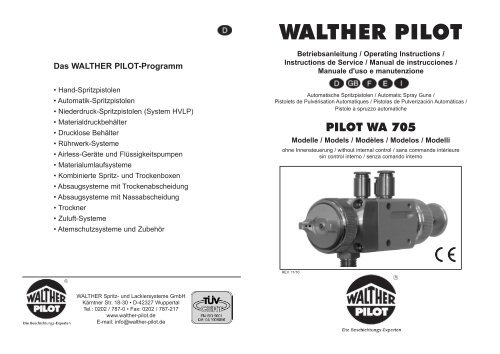
<strong>WA</strong>LTHER PILOT<br />
<strong>Betriebsanleitung</strong> / Operating Instructions /<br />
Instructions de Service / Manual de instrucciones /<br />
Manuale d'uso e manutenzione<br />
Automatische Spritzpistolen / Automatic Spray Guns /<br />
Pistolets de Pulvérisation Automatiques / Pistolas de Pulverización Automáticas /<br />
Pistole a spruzzo automatiche<br />
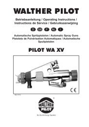
PILOT <strong>WA</strong> <strong>705</strong><br />
Modelle / Models / Modèles / Modelos / Modelli<br />
ohne Innensteuerung / without internal control / sans commande intérieure<br />
sin control interno / senza comando interno<br />
REV. <strong>11</strong>/10
PILOT <strong>WA</strong> <strong>705</strong><br />
Ohne Innensteuerung<br />
26<br />
25<br />
Stand: Januar 2010<br />
24<br />
28<br />
23<br />
18<br />
27<br />
17<br />
22<br />
16<br />
21<br />
15<br />
10<br />
14<br />
9<br />
20<br />
13<br />
8<br />
19<br />
12<br />
<strong>11</strong><br />
29<br />
30<br />
7<br />
6<br />
5
EG-Konformitätserklärung<br />
Wir, der Gerätehersteller, erklären in alleiniger Verantwortung, dass das Produkt in der untenstehenden<br />
Beschreibung den einschlägigen grundlegenden Sicherheits- und Gesundheitsanforderungen entspricht.<br />
Bei einer nicht mit uns abgestimmten Änderung an dem Gerät oder bei einer unsachgemäßen Verwendung verliert<br />
diese Erklärung ihre Gültigkeit.<br />
Hersteller <strong>WA</strong>LTHER Spritz- und Lackiersysteme GmbH<br />
Kärntner Str. 18 - 30<br />
D - 42327 Wuppertal<br />
Tel.: +49(0)202 / 787 - 0<br />
Fax: +49(0)202 / 787 - 2217<br />
www.walther-pilot.de • e-mail: info@walther-pilot.de<br />
Typenbezeichnung Automatische Spritzpistolen<br />
PILOT <strong>WA</strong> <strong>705</strong>-Serie ohne Innensteuerung<br />
<strong>WA</strong> <strong>705</strong> (Standard-Ausführung) V 20 <strong>705</strong><br />
<strong>WA</strong> 715-U (Standard-Umlauf-Ausführung) V 20 715<br />
<strong>WA</strong> 725-HVLP (Niederdruck-Ausführung) V 20 725<br />
<strong>WA</strong> 735-HVLP-U (Niederdruck-Umlauf-Ausführung) V 20 735<br />
<strong>WA</strong> 745-HVLP PLUS (Mitteldruck-Ausführung) V 20 745<br />
<strong>WA</strong> 755-HVLP PLUS-U (Mitteldruck-Umlauf-Ausführung) V 20 755<br />
<strong>WA</strong> 708-K (Standard-Kleber-Ausführung) V 20 708<br />
<strong>WA</strong> 718-U-K (Standard-Umlauf-Kleber-Ausf.) V 20 718<br />
<strong>WA</strong> 728-HVLP-K (Niederdruck-Kleber-Ausführung) V 20 728<br />
<strong>WA</strong> 738-HVLP-U-K (Niederdruck-Umlauf-Kleber-Ausf.) V 20 738<br />
Verwendungszweck Verarbeitung spritzbarer Materialien<br />
Angewandte Normen und Richtlinien<br />
EG-Maschinenrichtlinien 2006 / 42 / EG<br />
94 / 9 EG (ATEX Richtlinien)<br />
EN ISO 12100 Teil 1<br />
EN ISO 12100 Teil 2 DIN EN 1953<br />
DIN EN <strong>11</strong>27-1 DIN EN 13463-1<br />
Spezifikation im Sinne der Richtlinie 94 / 9 / EG<br />
Kategorie 2 Gerätebezeichnung II 2 G c T 5<br />
Tech.File,Ref.:<br />
2414<br />
Bevollmächtigt mit der Zusammenstellung der technischen Unterlagen:<br />
Nico Kowalski, <strong>WA</strong>LTHER Spritz- und Lackiersysteme GmbH, Kärntner Str. 18 - 30<br />
D- 42327 Wuppertal<br />
Besondere Hinweise :<br />
Das Produkt ist zum Einbau in ein anderes Gerät bestimmt. Die Inbetriebnahme ist so lange untersagt, bis die<br />
Konformität des Endproduktes mit der Richtlinie 2006 / 42 / EG festgestellt ist.<br />
Wuppertal, den 01. Januar 2010<br />
i.V.<br />
Name: Torsten Bröker<br />
Stellung im Betrieb: Leiter der Konstruktion und Entwicklung<br />
Diese Erklärung ist keine Zusicherung von Eigenschaften im Sinne der Produkthaftung. Die Sicherheitshinweise<br />
der Produktdokumentation sind zu beachten.<br />
Declaration of CE-Conformity<br />
We, the manufacturers of the equipment, hereby declare under our sole responsibility that the<br />
product(s) described below conform to the essential safety requirements. This declaration will be rendered invalid<br />
if any changes are made to the equipment without prior consultation with us.<br />
Manufacturer <strong>WA</strong>LTHER Spritz- und Lackiersysteme GmbH<br />
Kärntner Str. 18 - 30<br />
D - 42327 Wuppertal<br />
Tel.: +49(0)202 / 787 - 0<br />
Fax: +49(0)202 / 787 - 2217<br />
www.walther-pilot.de • e-mail: info@walther-pilot.de<br />
Type Designation Automatic Spray Gun<br />
PILOT <strong>WA</strong> <strong>705</strong>-Serie without internal control<br />
<strong>WA</strong> <strong>705</strong> (Standard) V 20 <strong>705</strong><br />
<strong>WA</strong> 715-U (Standard-circulation) V 20 715<br />
<strong>WA</strong> 725-HVLP (Low pressure) V 20 725<br />
<strong>WA</strong> 735-HVLP-U (Low pres.-circulation) V 20 735<br />
<strong>WA</strong> 745-HVLP PLUS (Medium pressure) V 20 745<br />
<strong>WA</strong> 755-HVLP PLUS-U (Medium pres.-circulation) V 20 755<br />
<strong>WA</strong> 708-K (Standard-adhesive version) V 20 708<br />
<strong>WA</strong> 718-U-K (Standard-adhesive vers.-circul.) V 20 718<br />
<strong>WA</strong> 728-HVLP-K (Low pressure-adhesive version) V 20 728<br />
<strong>WA</strong> 738-HVLP-U-K (Low pressure-adhesive vers.-circul.) V 20 738<br />
Intended purpose Processing of sprayable media<br />
Applied Standards and Directives<br />
EU-Mechanical Engineering Directives 2006 / 42 / EC<br />
94 / 9 EC (ATEX Directives)<br />
EN ISO 12100-1<br />
EN ISO 12100-2 DIN EN 1953<br />
DIN EN <strong>11</strong>27-1 DIN EN 13463-1<br />
Specification according 94 / 9 / EC<br />
Category 2 Part marking II 2 G c T 5<br />
Tech.File,Ref.:<br />
2414<br />
Authorized with the compilation of the technical file:<br />
Nico Kowalski, <strong>WA</strong>LTHER Spritz- und Lackiersysteme GmbH, Kärntner Str. 18 - 30<br />
D- 42327 Wuppertal<br />
Special remarks :<br />
The named product is intended for installation in other equipment. Commissioning is prohibited until such<br />
time as the end product has been proved to conform to the provision of the Directives 2006 / 42 / EC.<br />
Wuppertal, the 1st of January 2010<br />
i.V.<br />
Name: Torsten Bröker<br />
Position: Manager, Design and Development<br />
This Declaration does not give assurance of properties in the sense of product liability. The safety instructions<br />
provided in the product documentation must be observed at all times.
Déclaration de conformité EC<br />
En tant que fabricant de cet appareil, nous déclarons en toute responsabilité que le produit<br />
décrit ci-dessous est conforme aux exigences de sécurité et de protection<br />
de la santé actuellement en vigueur. Toute modification sans autorisation de notre part ou utilisation<br />
inadéquate de l'appareil, annulent la validité de cette déclaration.<br />
Fabricant <strong>WA</strong>LTHER Spritz- und Lackiersysteme GmbH<br />
Kärntner Str. 18 - 30<br />
D - 42327 Wuppertal<br />
Tel.: +49(0)202 / 787 - 0<br />
Fax: +49(0)202 / 787 - 2217<br />
www.walther-pilot.de • e-mail: info@walther-pilot.de<br />
Dénomination du<br />
modèle<br />
Pistolet automatique de pulvérisation<br />
Série PILOT <strong>WA</strong> <strong>705</strong> sans commande intérieure<br />
<strong>WA</strong> <strong>705</strong> (modèle standard) V 20 <strong>705</strong><br />
<strong>WA</strong> 715-U (modèle standard-circulating) V 20 715<br />
<strong>WA</strong> 725-HVLP (modèle basse pression) V 20 725<br />
<strong>WA</strong> 735-HVLP-U (modèle basse pression pour circul.) V 20 735<br />
<strong>WA</strong> 745-HVLP PLUS (modèle à pression intermédiaire) V 20 745<br />
<strong>WA</strong> 755-HVLP PLUS-U (mod.circulation à pression intermédiaire) V 20 755<br />
<strong>WA</strong> 708-K (mod. pour l’application de colles-stand.) V 20 708<br />
<strong>WA</strong> 718-U-K (mod.p.l’ap.de colles systèmes circulating) V 20 718<br />
<strong>WA</strong> 728-HVLP-K (mod.p.l’ap.de colle à basse pression) V 20 728<br />
<strong>WA</strong> 738-HVLP-U-K (modèle colle circulation à basse pression) V 20 738<br />
Utilisation Application de matières pulvérisables<br />
Normes et directives appliquées<br />
Directive UE sur les machines 2006 / 42 / EC<br />
94 / 9 EC (directives ATEX)<br />
EN ISO 12100-1<br />
EN ISO 12100-2 DIN EN 1953<br />
DIN EN <strong>11</strong>27-1<br />
Normes et directives appliquées 94 / 9 / EC<br />
DIN EN 13463-1<br />
Catégorie 2<br />
désignation de<br />
l'ap pareil<br />
II 2 G c T 5<br />
Personne chargée de la compilation des documents techniques :<br />
Nico Kowalski, <strong>WA</strong>LTHER Spritz- und Lackiersysteme GmbH, Kärntner Str. 18 - 30<br />
D- 42327 Wuppertal<br />
Tech.File,Ref.:<br />
2414<br />
Indications particulières:<br />
Le produit est conçu pour être intégré à un autre équipement. La mise en service n'est pas autorisée avant<br />
l'établissement de la conformité du produit final avec la directive 2006 / 42 / EC.<br />
Wuppertal, le 1 janvier 2010<br />
i.V.<br />
Nom: Torsten Bröker<br />
Position dans l'entreprise: chef de l'exécution et du développement<br />
Cette déclaration ne constitue pas un engagement de responsabilité dans le sens de la garantie du produit. Les<br />
consignes de sécurité contenues dans les instructions de service devront être respectées.<br />
Declaración de conformidad CE<br />
Como fabricante de este aparato, certificamos bajo nuestra plena responsabilidad<br />
que el producto descrito más abajo cumple con los requisitos de seguridad y protección de la salud en vigor.<br />
Cualquier modificación sin autorización previa o uso inadecuado del aparato anulan la validez de esta declaración.<br />
Fabricante <strong>WA</strong>LTHER Spritz- und Lackiersysteme GmbH<br />
Kärntner Str. 18 - 30<br />
D - 42327 Wuppertal<br />
Tel.: +49(0)202 / 787 - 0<br />
Fax: +49(0)202 / 787 - 2217<br />
www.walther-pilot.de • e-mail: info@walther-pilot.de<br />
Denominación del<br />
modelo<br />
Pistolas de pulverización automáticas<br />
Serie PILOT <strong>WA</strong> <strong>705</strong> sin control interno<br />
<strong>WA</strong> <strong>705</strong> (diseño estándar) V 20 <strong>705</strong><br />
<strong>WA</strong> 715-U (diseño de circulación estándar) V 20 715<br />
<strong>WA</strong> 725-HVLP (diseño de baja presión) V 20 725<br />
<strong>WA</strong> 735-HVLP-U (diseño de circulación debaja presión) V 20 735<br />
<strong>WA</strong> 745-HVLP PLUS (diseño de presión media) V 20 745<br />
<strong>WA</strong> 755-HVLP PLUS-U (diseño de circulación de presión media) V 20 755<br />
<strong>WA</strong> 708-K (diseño para colas estándar) V 20 708<br />
<strong>WA</strong> 718-U-K (diseño estándar de circulación para colas) V 20 718<br />
<strong>WA</strong> 728-HVLP-K (diseño para colas de bajapresión) V 20 728<br />
<strong>WA</strong> 738-HVLP-U-K (diseño de circulación para<br />
colas de baja presión) V 20 738<br />
Uso aplicación de materiales pulverizables<br />
Normas y directivas aplicadas<br />
Directiva EU sobre las máquinas 2006 / 42 / EC<br />
94 / 9 EC (directivas ATEX)<br />
EN ISO 12100-1<br />
EN ISO 12100-2 DIN EN 1953<br />
DIN EN <strong>11</strong>27-1<br />
Especificación en el sentido de 94 / 9 / EC<br />
DIN EN 13463-1<br />
Categoría 2<br />
designación del<br />
aparato<br />
II 2 G c T 5<br />
Persona autorizada para la compilación de la documentación técnica:<br />
Nico Kowalski, <strong>WA</strong>LTHER Spritz- und Lackiersysteme GmbH, Kärntner Str. 18 - 30<br />
D- 42327 Wuppertal<br />
Tech.File,Ref.:<br />
2414<br />
Indicaciones particulares:<br />
Este aparato está diseñado para integrarse a otro equipo. La puesta en marcha no se autoriza hasta que<br />
la conformidad del producto final con los requisitos de la directiva<br />
2006 / 42 / EC no haya sido establecida.<br />
Wuppertal, el 01 de enero 2010<br />
i.V.<br />
Nombre: Torsten Bröker<br />
Puesto: Jefe de la construcción y del desarrollo<br />
Esta declaración no constituye una declaración de responsabilidad en cuanto a la caracteristicas estipuladas en<br />
la garantía del aparato. Las consignas de seguridad de las instrucciones de uso deben seguirse.
Dichiarazione di conformità CE<br />
Noi, il costruttore, dichiariamo sotto la nostra esclusiva responsabilità che il prodotto qui di<br />
seguito descritto corrisponde ai requisiti di sicurezza e di salute essenziali in materia. In caso di<br />
modifica del prodotto non concordata con noi o in caso di uso improprio, la presente dichiarazione<br />
cessa di essere valida.<br />
Costruttore <strong>WA</strong>LTHER Spritz- und Lackiersysteme GmbH<br />
Kärntner Str. 18 - 30<br />
D - 42327 Wuppertal<br />
Tel.: +49(0)202 / 787 - 0<br />
Fax: +49(0)202 / 787 - 2217<br />
www.walther-pilot.de • e-mail: info@walther-pilot.de<br />
Designazione del tipo Pistole a spruzzo automatiche<br />
Serie PILOT <strong>WA</strong> <strong>705</strong> senza comando interno<br />
<strong>WA</strong> <strong>705</strong> (versione standard) V 20 <strong>705</strong><br />
<strong>WA</strong> 715-U (versione circolazione standard) V 20 715<br />
<strong>WA</strong> 725-HVLP (versione a bassa pressione) V 20 725<br />
<strong>WA</strong> 735-HVLP-U (versione circolazione a bassa pressione) V 20 735<br />
<strong>WA</strong> 745-HVLP PLUS (versione a media pressione) V 20 745<br />
<strong>WA</strong> 755-HVLP PLUS-U (versione circolazione a media pressione) V 20 755<br />
<strong>WA</strong> 708-K (versione standard collanti) V 20 708<br />
<strong>WA</strong> 718-U-K (versione circolazione standard collanti) V 20 718<br />
<strong>WA</strong> 728-HVLP-K (versione collanti a bassa pressione) V 20 728<br />
<strong>WA</strong> 738-HVLP-U-K (versione circolazione a bassa pressione coll.) V 20 738<br />
Uso previsto Applicazione di materiali spruzzabili<br />
Norme e direttive applicate<br />
Direttive macchine 2006 / 42 / EC<br />
94 / 9 EC (direttive ATEX)<br />
EN ISO 12100 parte 1<br />
EN ISO 12100 parte 2 DIN EN 1953<br />
DIN EN <strong>11</strong>27-1 DIN EN 13463 - 1<br />
Specifica ai sensi della direttiva 94 / 9 / EC<br />
Categoria 2<br />
Designazione dell'apparecchio<br />
II 2 G c T 5<br />
Tech.File,Ref.:<br />
2414<br />
Autorizzato alla raccolta della documentazione tecnica:<br />
Nico Kowalski, <strong>WA</strong>LTHER Spritz- und Lackiersysteme GmbH, Kärntner Str. 18 - 30<br />
D- 42327 Wuppertal<br />
Peculiarità :<br />
Il prodotto è previsto per essere incorporato in un altro apparecchio. La messa in sevizio non è consentita<br />
fino a quando non è stata constatata la conformità del prodotto finale con la direttiva 2006 / 42 / EC.<br />
Wuppertal, il 1 gennaio 2010<br />
per delega<br />
Nome e cognome: Torsten Bröker<br />
Posizione aziendale: Dirigente del reparto progettazione e sviluppo<br />
La presente dichiarazione non è una garanzia di caratteristiche nel senso della responsabilità del prodotto.<br />
Rispettare rigorosamente le avvertenze di sicurezza della documentazione del prodotto.
Ersatzteilliste:<br />
<strong>WA</strong> <strong>705</strong> <strong>WA</strong> 715-U <strong>WA</strong> 725-HVLP<br />
V 20 <strong>705</strong> V 20 715 V 20 725<br />
Pos. Bezeichnung Stck. Artikelnummer Stck. Artikelnummer Stck. Artikelnummer<br />
1 Luftkopfmutter kompl. 1 V 20 700 05 000 1 V 20 700 05 000 1 V 20 700 05 000<br />
2 Luftkopf 1 V 10 700 35 XX8 1 V 10 700 35 XX8 1 V 10 700 37 XXX<br />
3 Materialdüse * 1 V 10 700 40 XX3* 1 V 10 700 40 XX3* 1 V 10 700 40 XX3*<br />
5 Luftverteilerring 1 V 20 700 04 000 1 V 20 700 04 000 1 V 20 700 04 100<br />
6 Innensechskantschraube 4 V 20 700 13 003 4 V 20 700 13 003 4 V 20 700 13 003<br />
7 Pistolenvorderkörper komp. 1 V 20 700 03 000 1 V 20 710 03 000 1 V 20 700 03 000<br />
8 Stift für Luftkappenfixierung 1 V 20 700 02 303 1 V 20 700 02 303 1 V 20 700 02 303<br />
9 Arretierfeder 1 V 20 700 02 403 1 V 20 700 02 403 1 V 20 700 02 403<br />
10 Gewindestift 1 V 20 310 01 503 1 V 20 310 01 503 1 V 20 310 01 503<br />
<strong>11</strong> O-Ring 2 V 09 103 64 009 2 V 09 103 64 009 2 V 09 103 64 009<br />
12 Nadelpackung kompl. 1 V 09 001 72 000 1 V 09 001 72 000 1 V 09 001 72 000<br />
13 Druckstück 1 V 10 361 07 000 1 V 10 361 07 000 1 V 10 361 07 000<br />
14 Packungsfeder 1 V 20 510 12 003 1 V 20 510 12 003 1 V 20 510 12 003<br />
15 Packungsschraube 1 V 20 510 <strong>11</strong> 003 1 V 20 510 <strong>11</strong> 003 1 V 20 510 <strong>11</strong> 003<br />
16 Dichtschraube 1 V 22 650 43 100 1 V 22 650 43 100 1 V 22 650 43 100<br />
17 Nutring 1 V 09 220 30 000 1 V 09 220 30 000 1 V 09 220 30 000<br />
18 Kolbengehäuse kompl. 1 V 20 <strong>705</strong> 01 000 1 V 20 <strong>705</strong> 01 000 1 V 20 725 01 000<br />
19 Dichtsatz * 1 V 20 700 07 000* 1 V 20 700 07 000* 1 V 20 700 07 000*<br />
20 Kolben 1 V 20 <strong>705</strong> 08 000 1 V 20 <strong>705</strong> 08 000 1 V 20 <strong>705</strong> 08 000<br />
21 Kolbenfeder 1 V 20 606 <strong>11</strong> 000 1 V 20 606 <strong>11</strong> 000 1 V 20 606 <strong>11</strong> 000<br />
22 Gewindebuchse kompl. 1 V 20 700 09 000 1 V 20 700 09 000 1 V 20 700 09 000<br />
23 Materialnadel kompl. 1 V 20 <strong>705</strong> 30 XX3 1 V 20 <strong>705</strong> 30 XX3 1 V 20 <strong>705</strong> 30 XX3<br />
24 Nadelfeder 1 V 20 510 29 003 1 V 20 510 29 003 1 V 20 510 29 003<br />
25 Kappe kompl. 1 V 20 700 10 000 1 V 20 700 10 000 1 V 20 700 10 000<br />
26 Zugstange kompl. 1 V 20 510 34 000 1 V 20 510 34 000 1 V 20 510 34 000<br />
27 Steckverschraubung 2 V 66 101 53 015 2 V 66 101 53 015 2 V 66 101 53 015<br />
28 Steckverschraubung 1 V 66 101 53 013 1 V 66 101 53 013 1 V 66 101 53 013<br />
29 Doppelnippel G1/4 1 V 00 101 01 003 2 V 00 101 01 003 1 V 00 101 01 003<br />
30 Verschlussstopfen 1 V 20 540 40 003 entfällt 1 V 20 540 40 003<br />
Ersatzteilliste:<br />
<strong>WA</strong> 735-HVLP-U <strong>WA</strong> 745-HVLP PLUS <strong>WA</strong> 755-HVLP PLUS -U<br />
V 20 735 V 20 745 V 20 755<br />
Pos. Bezeichnung Stck. Artikelnummer Stck. Artikelnummer Stck. Artikelnummer<br />
1 Luftkopfmutter kompl. 1 V 20 700 05 000 1 V 20 700 05 000 1 V 20 700 05 000<br />
2 Luftkopf 1 V 10 700 37 XXX 1 V 10 700 36 XXX 1 V 10 700 36 XXX<br />
3 Materialdüse * 1 V 10 700 40 XX3* 1 V 10 700 40 XX3* 1 V 10 700 40 XX3*<br />
5 Luftverteilerring 1 V 20 700 04 100 1 V 20 700 04 100 1 V 20 700 04 100<br />
6 Innensechskantschraube 4 V 20 700 13 003 4 V 20 700 13 003 4 V 20 700 13 003<br />
7 Pistolenvorderkörper komp. 1 V 20 710 03 000 1 V 20 700 03 000 1 V 20 710 03 000<br />
8 Stift für Luftkappenfixierung 1 V 20 700 02 303 1 V 20 700 02 303 1 V 20 700 02 303<br />
9 Arretierfeder 1 V 20 700 02 403 1 V 20 700 02 403 1 V 20 700 02 403<br />
10 Gewindestift 1 V 20 310 01 503 1 V 20 310 01 503 1 V 20 310 01 503<br />
<strong>11</strong> O-Ring 2 V 09 103 64 009 2 V 09 103 64 009 2 V 09 103 64 009<br />
12 Nadelpackung kompl. 1 V 09 001 72 000 1 V 09 001 72 000 1 V 09 001 72 000<br />
13 Druckstück 1 V 10 361 07 000 1 V 10 361 07 000 1 V 10 361 07 000<br />
14 Packungsfeder 1 V 20 510 12 003 1 V 20 510 12 003 1 V 20 510 12 003<br />
15 Packungsschraube 1 V 20 510 <strong>11</strong> 003 1 V 20 510 <strong>11</strong> 003 1 V 20 510 <strong>11</strong> 003<br />
16 Dichtschraube 1 V 22 650 43 100 1 V 22 650 43 100 1 V 22 650 43 100<br />
17 Nutring 1 V 09 220 30 000 1 V 09 220 30 000 1 V 09 220 30 000<br />
18 Kolbengehäuse kompl. 1 V 20 <strong>705</strong> 01 000 1 V 20 <strong>705</strong> 01 000 1 V 20 <strong>705</strong> 01 000<br />
19 Dichtsatz * 1 V 20 700 07 000* 1 V 20 700 07 000* 1 V 20 700 07 000*<br />
20 Kolben 1 V 20 <strong>705</strong> 08 000 1 V 20 <strong>705</strong> 08 000 1 V 20 <strong>705</strong> 08 000<br />
21 Kolbenfeder 1 V 20 606 <strong>11</strong> 000 1 V 20 606 <strong>11</strong> 000 1 V 20 606 <strong>11</strong> 000<br />
22 Gewindebuchse kompl. 1 V 20 700 09 000 1 V 20 700 09 000 1 V 20 700 09 000<br />
23 Materialnadel kompl. 1 V 20 <strong>705</strong> 30 XX3 1 V 20 <strong>705</strong> 30 XX3 1 V 20 <strong>705</strong> 30 XX3<br />
24 Nadelfeder 1 V 20 510 29 003 1 V 20 510 29 003 1 V 20 510 29 003<br />
25 Kappe kompl. 1 V 20 700 10 000 1 V 20 700 10 000 1 V 20 700 10 000<br />
26 Zugstange kompl. 1 V 20 510 34 000 1 V 20 510 34 000 1 V 20 510 34 000<br />
27 Steckverschraubung 2 V 66 101 53 015 2 V 66 101 53 015 2 V 66 101 53 015<br />
28 Steckverschraubung 1 V 66 101 53 013 1 V 66 101 53 013 1 V 66 101 53 013<br />
29 Doppelnippel G1/4 2 V 00 101 01 003 1 V 00 101 01 003 2 V 00 101 01 003<br />
30 Verschlussstopfen entfällt 1 V 20 540 40 003 entfällt<br />
* Bei Ersatzteillieferungen bitte entsprechende Größe angeben. Wir empfehlen, alle fett-<br />
gedruckten Teile (Verschleißteile) auf Lager zu halten.
Reparatursets<br />
<strong>WA</strong>LTHER PILOT hält für die Automatik-Spritzpistolen PILOT <strong>WA</strong> <strong>705</strong> - <strong>WA</strong> 755 HVLPPLUS-U und<br />
die Ausführung für die Kleberverarbeitung PILOT <strong>WA</strong> 708-K - <strong>WA</strong> 738 HVLP-U-K Reparatursets<br />
bereit, die sämtliche Verschleißteile enthalten.<br />
Artikelnummer<br />
PILOT <strong>WA</strong> <strong>705</strong>/ 715 Standard-Version V 16 207 05 XX3<br />
PILOT <strong>WA</strong> 725 / 735 HVLP / Niederdruck-Version V 16 207 25 XX3<br />
PILOT <strong>WA</strong> 745 / 755 HVLPPLUS / Mitteldruck-Version V 16 207 45 XX3<br />
PILOT <strong>WA</strong> 708 / 718 Standard-Kleber-Version V 16 207 08 XX3<br />
PILOT <strong>WA</strong> 728 / 738 HVLP / Niederdruck-Kleber-Version V 16 207 28 XX3<br />
Düseneinlage<br />
Die Düseneinlagen bestehen aus Luftkopf, Materialdüse und Materialnadel<br />
PILOT <strong>WA</strong> <strong>705</strong>/ 715 Standard-Version<br />
Artikelnummer<br />
V 15 207 05 XX3<br />
PILOT <strong>WA</strong> 725 / 735 HVLP / Niederdruck-Version V 15 207 25 XX3<br />
PILOT <strong>WA</strong> 745 / 755 HVLPPLUS / Mitteldruck-Version V 15 207 45 XX3<br />
PILOT <strong>WA</strong> 708 / 718 Standard-Kleber-Version V 15 207 08 XX3<br />
PILOT <strong>WA</strong> 728 / 738 HVLP / Niederdruck-Kleber-Version V 15 207 28 XX3<br />
Düsenausstattung nach Wahl:<br />
▪ 0,3 ▪ 0,5 ▪ 0,8 ▪ 1,0 ▪ 1,2 ▪ 1,5 ▪ 1,8 ▪ 2,0 ▪ 2,2 ▪ 2,5 ▪ 3,0 ▪ 3,5 mm ø<br />
Inhaltsverzeichnis<br />
1 Allgemeines 2<br />
1.1 Kennzeichnung der Modelle 2<br />
1.2 Bestimmungsgemäße Verwendung 2<br />
1.3 Sachwidrige Verwendung 3<br />
2 Technische Beschreibung 3<br />
3 Sicherheitshinweise 4<br />
3.1 Kennzeichnung der Sicherheitshinweise 4<br />
3.2 Allgemeine Sicherheitshinweise 5<br />
4 Montage 6<br />
4.1 Spritzpistole befestigen 6<br />
4.2 Versorgungsleitungen anschließen 6<br />
5 Bedienung 7<br />
5.1 Sicherheitshinweise 7<br />
5.2 Inbetrieb- und Außerbetriebsetzen 7<br />
5.3 Spritzbildprobe erzeugen 7<br />
5.4 Spritzbild verändern 8<br />
5.5 Spritzpistole umrüsten 10<br />
6 Reinigung 10<br />
6.1 Sicherheitshinweise 10<br />
6.2 Grundreinigung <strong>11</strong><br />
6.3 Routinereinigung 12<br />
7 Instandsetzung 12<br />
7.1 Undichte Nadelpackung austauschen 13<br />
7.2 Materialdüse, -nadel, Federn und Dichtungen<br />
austauschen 13<br />
8 Fehlersuche und -beseitigung 14<br />
9 Entsorgung 14<br />
10 Technische Daten 15
1 Allgemeines<br />
1.1 Kennzeichnung der Modelle<br />
2<br />
Modelle: Automatische Spritzpistolen PILOT <strong>WA</strong> <strong>705</strong> - Serie ohne Innensteuerung<br />
Typen: <strong>WA</strong> <strong>705</strong> (Standard-Ausführung) V 20 <strong>705</strong><br />
<strong>WA</strong> 715-U (Standard-Umlauf-Ausführung) V 20 715<br />
<strong>WA</strong> 725-HVLP (Niederdruck-Ausführung) V 20 725<br />
<strong>WA</strong> 735-HVLP-U (Niederdruck-Umlauf-Ausführung) V 20 735<br />
<strong>WA</strong> 745-HVLP PLUS (Mitteldruck-Ausführung) V 20 745<br />
<strong>WA</strong> 755-HVLP PLUS-U (Mitteldruck-Umlauf-Ausführung) V 20 755<br />
<strong>WA</strong> 708-K (Standard-Kleber-Ausführung) V 20 708<br />
<strong>WA</strong> 718-U-K (Standard-Umlauf-Kleber-Ausführung) V 20 718<br />
<strong>WA</strong> 728-HVLP-K (Niederdruck-Kleber-Ausführung) V 20 728<br />
<strong>WA</strong> 738-HVLP-U-K (Niederdruck-Umlauf-Kleber-Ausf.) V 20 738<br />
Hersteller: <strong>WA</strong>LTHER Spritz- und Lackiersysteme GmbH<br />
Kärntner Str. 18-30<br />
D-42327 Wuppertal<br />
Tel.: 0202 / 787-0<br />
Fax: 0202 / 787-217<br />
www.walther-pilot.de • Email:info@walther-pilot.de<br />
1.2 Bestimmungsgemäße Verwendung<br />
Die automatischen Spritzpistolen der Baureihe PILOT <strong>WA</strong> <strong>705</strong> dienen ausschließlich<br />
der Verarbeitung spritzbarer Medien, wie z. B.:<br />
• Lacke und Farben<br />
• Fette, Öle und Korrosionsschutzmittel<br />
• Kleber<br />
• Trennmittel<br />
• Keramikglasuren<br />
• Beizen<br />
Sind die Materialien, die Sie verspritzen wollen, hier nicht aufgeführt, wenden Sie sich<br />
bitte an <strong>WA</strong>LTHER Spritz- und Lackiersysteme GmbH, Wuppertal.<br />
Die spritzbaren Materialien dürfen lediglich auf Werkstücke bzw. Gegenstände aufgetragen<br />
werden. Die Temperatur des Spritzmaterials darf 80°C grundsätzlich nicht überschreiten.<br />
Die Modelle der Baureihe PILOT <strong>WA</strong> 7XX Serie sind keine handgeführten<br />
Spritzpistolen und müssen deshalb an einer geeigneten Halterung befestigt werden.<br />
Die bestimmungsgemäße Verwendung schließt auch ein, dass alle Hinweise und<br />
Angaben der vorliegenden <strong>Betriebsanleitung</strong> gelesen, verstanden und beachtet werden.<br />
Das Gerät erfüllt die Explosionsschutz-Forderungen der Richtlinie 94 /9 EG (ATEX)<br />
für die auf dem Typenschild angegebene Explosionsgruppe, Gerätekategorie, und<br />
Temperaturklasse.<br />
Beim Betreiben des Gerätes sind die Vorgaben dieser <strong>Betriebsanleitung</strong> unbedingt<br />
einzuhalten. Die vorgeschriebenen Inspektions- und Wartungsintervalle sind einzuhalten.<br />
Die Angaben auf den Geräteschildern bzw. die Angaben in dem Kapitel technische<br />
Daten sind unbedingt einzuhalten und dürfen nicht überschritten werden. Eine<br />
Überlastung des Gerätes muss ausgeschlossen sein. Das Gerät darf in explosionsgefährdeten<br />
Bereichen nur nach Maßgabe der zuständigen Aufsichtsbehörde eingesetzt<br />
werden.<br />
Der zuständigen Aufsichtsbehörde bzw. dem Betreiber obliegt die Festlegung<br />
der Explosionsgefährdung (Zoneneinteilung).<br />
Es ist betreiberseitig zu prüfen und sicherzustellen, dass alle technischen Daten und<br />
die Kennzeichnung gemäß ATEX mit den notwendigen Vorgaben übereinstimmen.<br />
Bei Anwendungen, bei denen der Ausfall des Gerätes zu einer Personengefährdung<br />
führen könnte, sind betreiberseitig entsprechende Sicherheitsmaßnahmen vorzusehen.<br />
Falls im Betrieb Auffälligkeiten erkannt werden, muss das Gerät sofort stillgesetzt<br />
werden und es ist mit <strong>WA</strong>LTHER Spritz- und Lackiersysteme Rücksprache zu halten.<br />
Erdung / Potentialausgleich<br />
Es muss sichergestellt werden, dass die Spritzpistole separat oder in Verbindung mit<br />
dem Gerät auf dem sie aufgebaut ist, ausreichend geerdet ist (maximaler Widerstand<br />
10 6 Ω).<br />
1.3 Sachwidrige Verwendung<br />
Die Spritzpistole darf nicht anders verwendet werden, als es im Abschnitt 1.2<br />
Bestimmungsgemäße Verwendung geschrieben steht.<br />
Jede andere Verwendung ist sachwidrig.<br />
Zur sachwidrigen Verwendung gehören z.B.:<br />
• das Verspritzen von Materialien auf Personen und Tiere<br />
• das Verspritzen von flüssigem Stickstoff.<br />
2 Technische Beschreibung<br />
Die Modelle der Baureihe PILOT <strong>WA</strong> 7XX arbeiten vollautomatisch über eine<br />
Druckluftsteuerung und werden über ein 3/2-Wege-Steuerventil angesteuert.<br />
Dazu können Hand-, Fuß-oder Magnetventile eingesetzt werden.<br />
Zuerst wird die Zerstäuberluft (Rund- und Breitstrahlluft) (Pos. 27) über ein 3/2<br />
Wege-Steuerventil zugeschaltet. Danach wird die Steuerluft angesteuert, die den<br />
Kolben und die Materialnadel zurück drückt, um die Materialzufuhr zu öffnen.<br />
3
4<br />
Bei den Modellen PILOT <strong>WA</strong> 7XX wird die Form des Spritzstrahls (flach / breit /<br />
rund) über die beiden Druckluftregler in der Anlage eingestellt.<br />
Wird die Steuerluft durch das 3/2-Wege-Steuerventil unterbrochen, bewegt der<br />
Federdruck den Kolben und die Materialnadel in ihrer Ausgangsstellung zurück und<br />
verschließt die Materialzufuhr zur Materialdüse. Anschließend wird die<br />
Zerstäuberluft abgeschaltet.<br />
Die Materialdurchflussmenge wird bei allen Modellen über den Materialdruck und<br />
durch Begrenzung des Öffnungsweges der Materialnadel an der Kappe (Pos. 25)<br />
eingestellt. Der Materialdurchfluss der Automatik-Spritzpistolenserie<br />
PILOT <strong>WA</strong> 7XX kann auch von Hand mit Hilfe der Zugstange (Pos. 26) geöffnet<br />
werden, um dadurch z. B. eine verstopfte Materialdüse zu reinigen.<br />
Die Spritzpistolen der PILOT <strong>WA</strong> 7XX-Serie können an Materialdruckgefäßen und<br />
Pumpensystemen angeschlossen werden.<br />
Die Modelle PILOT <strong>WA</strong> 715-U / <strong>WA</strong> 735-HVLP-U / <strong>WA</strong> 755-HVLP PLUS-U /<br />
<strong>WA</strong> 718-U-K und <strong>WA</strong> 738-HVLP-U-K mit Anschluss für Farbumlauf können in eine<br />
Anlage mit Zirkulation eingebunden werden.<br />
Die Modelle PILOT <strong>WA</strong> 725-HVLP / <strong>WA</strong> 735 HVLP-U / <strong>WA</strong> 728 HVLP-K und<br />
<strong>WA</strong> 738 HVLP-U-K sind reine Niederdruck-Spritzpistolen und arbeiten mit einem<br />
Spritzluftdruck von 0,7 bar bei einem Eingangsluftdruck von 4,5 bar.<br />
Bei den Modelle PILOT <strong>WA</strong> 745-HVLP PLUS und <strong>WA</strong> 755 HVLP PLUS-U<br />
beträgt der Eingangsluftdruck von 3,0 bis 3,3 bar für einen Spritzluftdruck von 1,2<br />
bis 1,4 bar.<br />
3 Sicherheitshinweise<br />
3.1 Kennzeichnung der Sicherheitshinweise<br />
Warnung<br />
Das Piktogramm und die Dringlichkeitsstufe „Warnung“ kennzeichnen eine mögliche<br />
Gefahr für Personen.<br />
Mögliche Folgen: schwere oder leichte Verletzungen.<br />
Achtung<br />
Das Piktogramm und die Dringlichkeitsstufe „Achtung“ kennzeichnen eine mögliche<br />
Gefahr für Sachwerte.<br />
Mögliche Folgen: Beschädigung von Sachen.<br />
Hinweis<br />
Das Piktogramm und die Dringlichkeitsstufe „Hinweis“ kennzeichnen zusätzliche<br />
Informationen für das sichere und effiziente Arbeiten mit der Spritzpistole.<br />
3.2 Allgemeine Sicherheitshinweise<br />
► Die einschlägigen Unfallverhütungsvorschriften sowie die sonstigen anerkann-<br />
ten sicherheitstechnischen und arbeitsmedizinischen Regeln sind einzuhalten.<br />
► Benutzen Sie die Spritzpistole nur in gut belüfteten Räumen. Im Arbeitsbereich<br />
ist Feuer, offenes Licht und Rauchen verboten. Beim Verspritzen leichtentzünd-<br />
licher Materialien (z. B. Lacke, Kleber, Reinigungsmittel usw.) besteht erhöhte<br />
Gesundheits-, Explosions- und Brandgefahr.<br />
► Es muss sichergestellt werden, dass die Spritzpistole separat oder in<br />
Verbindung mit dem Gerät auf dem sie aufgebaut ist, ausreichend geerdet ist<br />
(max. Widerstand 10 6 Ω).<br />
► Schalten Sie vor jeder Wartung und Instandsetzung die Luft- und<br />
Materialzufuhr zur Spritzpistole drucklos - Verletzungsgefahr.<br />
► Halten Sie beim Verspritzen von Materialien keine Hände oder andere<br />
Körperteile vor die unter Druck stehende Düse der Spritzpistole -<br />
Verletzungsgefahr.<br />
► Richten Sie die Spritzpistole nicht auf Personen und Tiere - Verletzungsgefahr.<br />
► Beachten Sie die Verarbeitungs- und Sicherheitshinweise der Hersteller von<br />
Spritzmaterial und Reinigungsmittel. Insbesondere aggressive und ätzende<br />
Materialien können gesundheitliche Schäden verursachen.<br />
► Tragen Sie im Arbeitsbereich der Spritzpistole einen Gehörschutz. Der erzeug-<br />
te Schallpegel der Spritzpistole von ca. 86 dB (A) kann einen Gehörschaden<br />
verursachen.<br />
► Die partikelführende Abluft ist vom Arbeitsbereich und Betriebspersonal fernzu-<br />
halten. Tragen Sie dennoch vorschriftsgemäßen Atemschutz und vorschriftsge-<br />
mäße Arbeitskleidung, wenn Sie mit der Spritzpistole Materialien verarbeiten.<br />
Umherschwebende Partikel gefährden Ihre Gesundheit.<br />
► Achten Sie stets darauf, dass nach den Montage- und Wartungsarbeiten alle<br />
Muttern und Schrauben fest angezogen sind.<br />
► Verwenden Sie nur Original-Ersatzteile, da <strong>WA</strong>LTHER nur für diese eine siche-<br />
re und einwandfreie Funktion garantieren kann.<br />
► Bei Nachfragen zur gefahrlosen Benutzung der Spritzpistole sowie der darin<br />
verwendeten Materialien, wenden Sie sich bitte an <strong>WA</strong>LTHER Spritz- und<br />
Lackiersysteme GmbH, D-42327 Wuppertal.<br />
5
6<br />
4 Montage<br />
Die Spritzpistole ist werkseitig komplett montiert. Bevor Sie die Spritzpistole in<br />
Betrieb setzen können, sind die folgenden Tätigkeiten durchzuführen:<br />
4.1 Spritzpistole befestigen<br />
Befestigen Sie die Spritzpistole an einer geeigneten, standsicheren Halterung, wie<br />
im folgenden Beispiel beschrieben:<br />
4.2 Versorgungsleitungen anschließen<br />
Warnung<br />
Achten Sie darauf, dass die Anschlüsse der Steuer- und Zerstäuberluft (Rund/<br />
Breitstrahl) nicht vertauscht werden - Verletzungsgefahr.<br />
4<br />
(2) (1)<br />
2<br />
3<br />
1<br />
Benutzen Sie hierzu die beiden<br />
Durchgangsbohrungen Ø 5,3 mm<br />
(1 )mit einem Lochabstand von<br />
28 mm und die beiden<br />
Gewindebohrungen M5 mit einem<br />
Lochabstand von 28 mm (2)<br />
Andere Befestigungsvorrichtungen<br />
auf Anfrage.<br />
1 = Materialanschluss (G 1/4“)<br />
2 = Steuerluftanschluss (G 1/8“) gekennzeichnet mit ST<br />
3 = Breitstrahlluftanschluss (G 1/8") gekennzeichnet mit B<br />
4 = Rundstrahlluftanschluss (G 1/8") gekennzeichnet mit R<br />
5 = Materialanschlüsse (G 1/4“) für Umlaufversionen der PILOT <strong>WA</strong> 7XX Modelle<br />
Die Spritzpistole ist nun vollständig montiert und kann in Betrieb gesetzt werden.<br />
5<br />
5<br />
5 Bedienung<br />
5.1 Sicherheitshinweise<br />
Beachten Sie bei der Bedienung der Spritzpistole insbesondere die nachfolgenden<br />
Sicherheitshinweise!<br />
• Tragen Sie vorschriftsmäßigen Atemschutz und Arbeitskleidung, wenn Sie mit<br />
der Spritzpistole Materialien verspritzen. Umherschwebende Partikel gefährden<br />
Ihre Gesundheit.<br />
• Tragen Sie im Arbeitsbereich der Spritzpistole einen Gehörschutz. Der erzeugte<br />
Schallpegel der Spritzpistole von ca. 86 dB (A) kann einen Gehörschaden<br />
verursachen.<br />
• Im Arbeitsbereich ist Feuer, offenes Licht und Rauchen verboten. Beim<br />
Verspritzen leicht entzündbarer Materialien (z. B. Lacke, Kleber) besteht erhöhte<br />
Explosions- und Brandgefahr.<br />
5.2 Inbetrieb- und Außerbetriebsetzen<br />
Bevor Sie die Spritzpistole in Betrieb setzen können, müssen folgende<br />
Voraussetzungen erfüllt sein:<br />
• Der Steuerluftdruck muss an der Spritzpistole anstehen<br />
• Der Zerstäuberluftdruck muss an der Spritzpistole anstehen<br />
• Der Materialdruck muss an der Spritzpistole anstehen.<br />
Achtung<br />
Der Materialdruck darf nicht höher eingestellt sein als • 8 bar, da sonst kein funktionssicherer<br />
Betrieb der Spritzpistole gewährleistet ist.<br />
Stellen Sie den Steuerluftdruck auf • mindestens 4,5 bar, damit die Spritzpistole<br />
in Betrieb gesetzt werden kann.<br />
Sie können die Spritzpistole in und außer Betrieb setzen, indem Sie das<br />
3/2-Wege-Steuerventil betätigen (siehe <strong>Betriebsanleitung</strong> des Anlagenherstellers).<br />
Warnung<br />
Die Spritzpistole muss nach Arbeitsende immer drucklos geschaltet werden. Die<br />
unter Druck stehenden Leitungen können platzen und nahestehende Personen<br />
durch das ausströmende Material verletzen.<br />
5.3 Spritzbildprobe erzeugen<br />
Eine Spritzbildprobe sollte immer dann erzeugt werden, wenn<br />
• die Spritzpistole zum ersten Mal in Betrieb gesetzt wird<br />
• das Spritzmaterial ausgetauscht wird<br />
• die Pistole zur Wartung oder Instandsetzung zerlegt wurde.<br />
Die Spritzbildprobe kann auf ein Probewerkstück, Blech, Pappe oder Papier abgegeben<br />
werden.<br />
7
8<br />
Warnung<br />
Halten Sie beim Verspritzen von Materialien keine Hände oder andere Körperteile<br />
vor die unter Druck stehende Düse der Spritzpistole - Verletzungsgefahr.<br />
Warnung<br />
Achten Sie beim Inbetriebsetzen der Spritzpistole darauf, dass sich keine Person<br />
im Spritzbereich befindet - Verletzungsgefahr<br />
1. Setzen Sie die Spritzpistole in Betrieb, um eine Spritzbildprobe zu erzeugen<br />
(siehe 5.2 Inbetrieb- und Außerbetriebsetzen).<br />
2. Kontrollieren Sie die Spritzbildprobe und verändern Sie ggf. die Einstellungen<br />
an der Spritzpistole (siehe 5.4 Spritzbild verändern).<br />
5.4 Spritzbild verändern<br />
Sie können an den Spritzpistolen der Baureihe PILOT <strong>WA</strong> <strong>705</strong> durch die folgenden<br />
Einstellungen das Spritzbild verändern.<br />
Spritzluft einstellen<br />
R<br />
B<br />
Materialdurchflussmenge einstellen<br />
1<br />
2<br />
Das Spritzbild wird über einen Druckluftregler in<br />
der Anlage eingestellt (siehe <strong>Betriebsanleitung</strong><br />
des Anlagen-Herstellers).<br />
Der Anschluss (B) ist für die Breitstrahlluft, der<br />
Anschluss (R) ist für die Rundstrahlluft.<br />
Drehen Sie die Kappe (1) aus der Grundeinstellung<br />
• nach innen, um den Materialdurchfluss zu<br />
verringern.<br />
• nach außen, um den Materialdurchfluss zu<br />
erhöhen.<br />
Mit Hilfe der Zugstange (2) kann der<br />
Materialdurchfluss durch die Düse betätigt werden,<br />
ohne dass die Zerstäuberluft eingeschaltet<br />
wird.<br />
Materialdruck regulieren<br />
Diese Einstellung können Sie nur an der Pumpe oder am Druckbehälter vornehmen.<br />
Beachten Sie dabei die Anweisungen und Sicherheitshinweise des Herstellers.<br />
Zerstäuberluftdruck regulieren<br />
Der Zerstäuberluftdruck wird am Druckluft-Reduzierventil der Kompressoranlage eingestellt.<br />
Beachten Sie die Anweisungen und Sicherheitshinweise des Herstellers.<br />
Wenn Sie das Spritzbild über die bereits erwähnten Möglichkeiten hinaus verändern<br />
wollen, muss die Spritzpistole umgerüstet werden (siehe 5.5 Spritzpistole umrüsten).<br />
<strong>WA</strong>LTHER bietet dazu eine Vielzahl unterschiedlicher Luftkopf-/ Materialdüse-/<br />
Nadel-Kombinationen an.<br />
Mängel eines Spritzbildes beheben<br />
Die folgende Tabelle zeigt Ihnen, mit welchen Einstellungen Sie das Spritzbild beeinflussen<br />
können.<br />
angestrebtes Spritzergebnis<br />
Spritzbildprobe Abweichung erforderliche Einstellung<br />
Spritzbild ist in der Mitte<br />
zu dick<br />
Spritzbild ist an den<br />
Enden zu dick<br />
Spritzbild ist ziemlich<br />
grobtropfig<br />
Materialauftrag ist in der<br />
Spritzbildmitte sehr dünn<br />
Spritzbild ist in der Mitte<br />
gespalten<br />
• breitere Spritzstrahlform<br />
einstellen<br />
• rundere Spritzstrahlform<br />
einstellen<br />
• Zerstäuberluftdruck<br />
erhöhen<br />
• Zerstäuberluftdruck<br />
verringern<br />
• Düsendurchmesser erhöhen<br />
• Zerstäuberluftdruck verrin -<br />
gern<br />
• Materialdruck erhöhen<br />
Spritzbild ist sehr ballig • Materialdruck verringern<br />
• Zerstäuberluftdruck erhöhen<br />
9
10<br />
5.5 Spritzpistole umrüsten<br />
Die zum Spritzmaterial passende Luftkopf-/ Materialdüse-/ Nadel-Kombination bildet<br />
eine aufeinander abgestimmte Einheit - die Düseneinlage. Tauschen Sie immer die<br />
komplette Düseneinlage aus, damit die gewünschte Spritzbildqualität erhalten bleibt.<br />
Warnung<br />
Schalten Sie vor jeder Umrüstung die Steuer- und Zerstäuberluft sowie die Mate-<br />
rialzufuhr zur Spritzpistole drucklos - Verletzungsgefahr.<br />
Hinweis<br />
Zur Durchführung der im Folgenden aufgeführten Arbeitsschritte benutzen Sie bitte<br />
die Explosionszeichnung am Anfang dieser <strong>Betriebsanleitung</strong>.<br />
Luftkopf wechseln<br />
1. Schrauben Sie die geriffelte Luftkopfmutter (Pos. 1) vom Pistolenvorderkörper<br />
ab.<br />
2. Ziehen Sie den Luftkopf (Pos. 2) vom Pistolenvorderkörper (Pos. 7) herunter.<br />
3. Setzen Sie den gewünschten Luftkopf auf den Pistolenvorderkörper.<br />
4. Schrauben Sie die Luftkopfmutter (Pos. 1) auf den Pistolenvorderkörper.<br />
Materialdüse und Materialnadel wechseln<br />
1. Entfernen Sie den Luftkopf (Pos. 2) (siehe 5.5 Luftkopf wechseln).<br />
2. Schrauben Sie die Materialdüse (Pos. 3) aus dem Pistolenvorderkörper (Pos. 7)<br />
(SW 13).<br />
3. Schrauben Sie die Zugstange (Pos. 26) aus der Materialnadel (Pos. 23) heraus.<br />
4. Schrauben Sie die Kappe (Pos. 25) von der Gewindebuchse (Pos. 22) ab.<br />
5. Ziehen Sie die Materialnadel (Pos. 23) aus dem Kolbengehäuse (Pos. 18).<br />
Die Montage der neuen Düseneinlage sowie der restlichen Bauteile erfolgt in umgekehrter<br />
Reihenfolge.<br />
6 Reinigung<br />
6.1 Sicherheitshinweise<br />
• Schalten Sie vor jeder Wartung die Steuer- und Zerstäuberluft sowie die<br />
Materialzufuhr zur Spritzpistole drucklos - Verletzungsgefahr.<br />
• Im Arbeitsbereich ist Feuer, offenes Licht und Rauchen verboten. Beim<br />
Verspritzen leichtentzündlicher Materialien (z. B. Reinigungsmittel) besteht<br />
erhöhte Explosions- und Brandgefahr.<br />
• Beachten Sie die Sicherheitshinweise des Reinigungsmittel-Herstellers. Insbeson-<br />
dere aggressive und ätzende Reinigungsmittel können gesundheitliche Schäden<br />
verursachen.<br />
6.2 Grundreinigung<br />
Damit die Lebensdauer und die Funktion der Spritzpistole lange erhalten bleibt,<br />
muss die Spritzpistole regelmäßig gereinigt und geschmiert werden. Verwenden Sie<br />
zur Reinigung der Spritzpistole nur Reinigungsmittel, die vom Hersteller des<br />
Spritzmaterials angegeben werden und die folgenden Bestandteile nicht enthalten:<br />
• halogenierte Kohlenwasserstoffe<br />
(z. B. 1,1,1, Trichlorethan, Methylen-Chlorid usw.)<br />
• Säuren und säurehaltige Reinigungsmittel<br />
• regenerierte Lösemittel (sog. Reinigungsverdünnungen)<br />
• Entlackungsmittel.<br />
Die o. g. Bestandteile verursachen an galvanisierten Bauteilen chemische<br />
Reaktionen und führen zu Korrosionsschäden.<br />
Für Schäden, die aus einer derartigen Behandlung herrühren, übernimmt<br />
<strong>WA</strong>LTHER Spritz- und Lackiersysteme keine Gewährleistung.<br />
Reinigen Sie die Spritzpistole<br />
• vor jedem Farb- bzw. Materialwechsel<br />
• mindestens einmal wöchentlich<br />
• materialabhängig und je nach Verschmutzungsgrad mehrfach wöchentlich.<br />
Achtung<br />
Legen Sie die Spritzpistole nie in Lösemittel oder ein anderes Reinigungsmittel. Die<br />
einwandfreie Funktion der Spritzpistole kann sonst nicht garantiert werden.<br />
Achtung<br />
Verwenden Sie zur Reinigung keine harten oder spitzen Gegenstände.<br />
Präzisionsteile der Spritzpistole könnten sonst beschädigt werden und das<br />
Spritzergebnis verschlechtern.<br />
1. Zerlegen Sie die Pistole gemäß 5.5 Materialdüse und -nadel wechseln.<br />
2. Reinigen Sie den Luftkopf und die Materialdüse mit einem Pinsel und dem<br />
Reinigungsmittel.<br />
3. Reinigen Sie alle übrigen Bauteile und den Pistolenkörper mit einem Tuch und<br />
dem Reinigungsmittel.<br />
4. Bestreichen Sie folgende Teile mit einem dünnen Fettfilm:<br />
• Manschette des Kolbens<br />
• O-Ring des Kolbens<br />
• Materialnadel<br />
• Nadelfeder<br />
Verwenden Sie dazu ein säurefreies, nicht harzendes Fett und einen Pinsel.<br />
Anschließend wird die Spritzpistole in umgekehrter Reihenfolge zusammengesetzt.<br />
<strong>11</strong>
12<br />
6.3 Routinereinigung<br />
Bei regelmäßigen Farbwechseln oder (materialabhängig) nach Arbeitsende können<br />
Sie die Spritzpistole auch reinigen, ohne diese dabei zerlegen zu müssen.<br />
Hinweis<br />
Reinigen und schmieren Sie die Spritzpistole dennoch regelmäßig gemäß Ab-<br />
schnitt 6.2 Grundreinigung. Sie erhalten so die sichere Funktion der Spritzpistole.<br />
Um die Routinereinigung durchführen zu können, müssen Sie die folgenden<br />
Arbeitsschritte durchführen:<br />
1. Befüllen Sie den gesäuberten Materialbehälter mit einem geeigneten Reinig-<br />
ungsmittel. Lediglich der Materialdruck muss an der Spritzpistole anstehen.<br />
Das Reinigungsmittel sollte nicht zerstäubt werden.<br />
2. Setzen Sie die Spritzpistole in Betrieb, (siehe 5.2 Inbetriebsetzen).<br />
3. Setzen Sie die Spritzpistole erst außer Betrieb, wenn diese nur noch klares<br />
Reinigungsmittel verspritzt.<br />
Damit nicht die gesamte Spritzanlage in Betrieb gesetzt werden muss, können Sie<br />
die Materialzufuhr der PILOT <strong>WA</strong> <strong>705</strong> - Baureihe auch von Hand entsperren.<br />
Die gesamte Spritzanlage sollte nun bis zum nächsten Einsatz drucklos<br />
geschaltet werden.<br />
7 Instandsetzung<br />
1. Ziehen Sie die Zugstange der Spritzpistole<br />
nach hinten. Die Materialzufuhr wird geöffnet<br />
und Materialkanal und -düse werden gereinigt.<br />
2. Lassen Sie die Zugstange erst los, wenn an der<br />
Spritzpistole nur noch klares Reinigungsmittel<br />
austritt.<br />
Warnung<br />
Schalten Sie vor jeder Instandsetzung die Steuer- und Zerstäuberluft sowie die<br />
Materialzufuhr zur Spritzpistole drucklos - Verletzungsgefahr.<br />
Hinweis<br />
Zur Durchführung der im Folgenden aufgeführten Arbeitsschritte benutzen Sie bitte<br />
die Explosionszeichnung am Anfang dieser <strong>Betriebsanleitung</strong>.<br />
7.1 Undichte Nadelpackung austauschen<br />
1. Schalten Sie die Pistole drucklos.<br />
2. Schrauben Sie die 4 Befestigungsschrauben (Pos. 6) aus dem Pistolenvorderkörper<br />
(Pos. 7) (Innensechskant SW 3).<br />
3. Ziehen Sie den Pistolenvorderkörper (Pos. 7) vom Kolbengehäuse (Pos. 18).<br />
4. Schrauben Sie die Packungsschraube (Pos. 15) aus dem Vorderkörper (Pos. 7)<br />
(Schraubendreher).<br />
5. Entfernen Sie die Packungsfeder (Pos. 14) (austauschen, falls beschädigt) und<br />
das Druckstück (Pos. 13) aus der Einschrauböffnung.<br />
6. Ziehen Sie die Nadelpackung (Pos. 12) mit einem Hilfswerkzeug aus ihrem Sitz.<br />
Verwenden Sie hierzu einen festen Draht, dessen Ende zu einem kleinen Haken<br />
umgebogen ist.<br />
7. Fetten Sie die neu einzusetzende Nadelpackung mit einem säurefreien, nicht<br />
harzenden Fett ein.<br />
8. Setzen Sie die neue Nadelpackung in den Pistolenvorderkörper ein.<br />
Die Montage der restlichen Bauteile erfolgt in umgekehrter Reihenfolge.<br />
Hinweis<br />
Die aus dem Pistolenvorsatz entnommene Nadelpackung (Pos. 12) darf nicht wiederverwendet<br />
werden, da sonst eine funktionssichere Dichtwirkung nicht gewährleistet<br />
ist.<br />
7.2 Materialdüse, -nadel, Federn und Dichtungen austauschen<br />
Zerlegen Sie die Spritzpistole gemäß Abschnitt 5.5 Materialdüse und -nadel wechseln,<br />
wenn die folgenden Bauteile ausgetauscht werden müssen:<br />
• Materialdüse<br />
• Druckfeder des Kolbens<br />
• Materialnadel*<br />
• Nadelfeder*<br />
• Manschette des Kolbens*<br />
• O-Ring des Kolbens*<br />
Hinweis<br />
Die mit * gekennzeichneten Bauteile müssen vor dem Einbau in den Pistolenkörper<br />
mit einem säurefreien, nicht harzenden Fett eingefettet werden.<br />
<strong>WA</strong>LTHER Spritz- und Lackiersysteme hält für die Automatik-Spritzpistolen der<br />
Baureihe PILOT <strong>WA</strong> <strong>705</strong> Reparatursets bereit, die sämtliche Verschleißteile enthalten:<br />
Art. Nr.: V 15 207 05 . . 3 (<strong>WA</strong> <strong>705</strong> / <strong>WA</strong> 715)<br />
Art. Nr.: V 15 207 25 . . 3 (<strong>WA</strong> 725 / <strong>WA</strong> 735)<br />
Art. Nr.: V 15 207 45 . . 3 (<strong>WA</strong> 745 / <strong>WA</strong> 755)<br />
Art. Nr.: V 15 207 08 . . 3 (<strong>WA</strong> 708 / <strong>WA</strong> 718)<br />
Art. Nr.: V 15 207 28 . . 3 (<strong>WA</strong> 728 / <strong>WA</strong> 738)<br />
Die Verschleißteile sind auch in der Ersatzteilliste aufgeführt (durch Fettdruck<br />
gekennzeichnet).<br />
13
8 Fehlersuche und -beseitigung<br />
Warnung<br />
Schalten Sie vor jeder Wartung und Instandsetzung die Steuer- und Zerstäuberluft<br />
sowie Materialzufuhr zur Spritzpistole drucklos - Verletzungsgefahr.<br />
Fehler Ursache Abhilfe<br />
Pistole tropft Materialnadel oder -düse<br />
verschmutzt<br />
Materialnadel oder -düse<br />
beschädigt<br />
Packungsschraube zu<br />
fest angezogen<br />
siehe 5.5 Materialnadel<br />
oder -düse ausbauen und reinigen<br />
siehe 7.2 Materialnadel oder<br />
-düse austauschen<br />
Packungsschraube (Pos. 15)<br />
mit Schraubendreher etwas<br />
lösen<br />
Pistole öffnet nicht Steuerluft zu niedrig Steuerluftdruck erhöhen<br />
auf min. 4,5 bar<br />
Material tritt an der<br />
Leckagebohrung aus<br />
Stoßweiser oder flatternder<br />
Spritzstahl<br />
9 Entsorgung<br />
Nadelpackung ist undicht<br />
Packungsschraube ist<br />
lose<br />
zu wenig Material im<br />
Materialbehälter<br />
siehe 7.1 Nadelpackung<br />
austauschen<br />
Packungsschraube (Pos. 15)<br />
mit Schraubendreher etwas<br />
anziehen<br />
Material auffüllen (siehe<br />
<strong>Betriebsanleitung</strong> des<br />
Anlagenherstellers)<br />
Die bei der Reinigung und Wartung anfallenden Materialien sind den Gesetzen und<br />
Vorschriften entsprechend sach- und fachgerecht zu entsorgen.<br />
Warnung<br />
Beachten Sie insbesondere die Hinweise des Herstellers der Spritz- und<br />
Reinigungsmittel. Unachtsam entsorgtes Material gefährdet die Gesundheit von<br />
Mensch und Tier.<br />
10 Technische Daten<br />
Gewicht: 623 g<br />
Düsengrößen: ▪ 0,3 ▪ 0,5 ▪ 0,8 ▪ 1,0 ▪ 1,2 ▪ 1,5 ▪ 1,8 ▪ 2,0<br />
▪ 2,2 ▪ 2,5 ▪ 3,0 ▪ 3,5 mm ø<br />
Anschluss:<br />
Zerstäuberluft G 1/8“<br />
Steuerluft G 1/8“<br />
Materialzufuhr G 1/4“<br />
Druckbereiche:<br />
Steuerluft mind. 4,5 bar<br />
Materialdruck max. 8 bar<br />
Zerstäuberluft max. 8 bar<br />
max. Betriebstemperatur<br />
der Spritzpistole 80 °C<br />
Schallpegel<br />
(gemessen in ca. 1 m<br />
Abstand zur Spritzpistole) 86 dB (A)<br />
Luftverbrauch:<br />
Luftkopf Eingangsluftdruck<br />
an der Pistole<br />
Luftverbrauch<br />
PILOT <strong>WA</strong> <strong>705</strong> / 715 1031 4,0 bar 360 L/min.<br />
PILOT <strong>WA</strong> 725 / 735<br />
HVLP<br />
PILOT <strong>WA</strong> 745 / 755<br />
HVLPPLUS Technische Änderungen vorbehalten.<br />
1061 3,5 bar 340 L/min.<br />
1060 3,4 bar 290 L/min.<br />
14 15
Listing of Replacement Parts:<br />
<strong>WA</strong> <strong>705</strong> <strong>WA</strong> 715-U <strong>WA</strong> 725-HVLP<br />
V 20 <strong>705</strong> V 20 715 V 20 725<br />
Item Description piece Parts No. piece Parts No. piece Parts No.<br />
1 Retaining Ring compl. 1 V 20 700 05 000 1 V 20 700 05 000 1 V 20 700 05 000<br />
2 Air Cap 1 V 10 700 35 XX8 1 V 10 700 35 XX8 1 V 10 700 37 XXX<br />
3 Material nozzle * 1 V 10 700 40 XX3* 1 V 10 700 40 XX3* 1 V 10 700 40 XX3*<br />
5 Sealing Washer 1 V 20 700 04 000 1 V 20 700 04 000 1 V 20 700 04 100<br />
6 Hexagon socket screw 4 V 20 700 13 003 4 V 20 700 13 003 4 V 20 700 13 003<br />
7 Front Body compl. 1 V 20 700 03 000 1 V 20 710 03 000 1 V 20 700 03 000<br />
8 Pin to fix air cap 1 V 20 700 02 303 1 V 20 700 02 303 1 V 20 700 02 303<br />
9 Locking spring 1 V 20 700 02 403 1 V 20 700 02 403 1 V 20 700 02 403<br />
10 Set screw 1 V 20 310 01 503 1 V 20 310 01 503 1 V 20 310 01 503<br />
<strong>11</strong> O-Ring 2 V 09 103 64 009 2 V 09 103 64 009 2 V 09 103 64 009<br />
12 Needle seal Packing com. 1 V 09 001 72 000 1 V 09 001 72 000 1 V 09 001 72 000<br />
13 Pressure peace 1 V 10 361 07 000 1 V 10 361 07 000 1 V 10 361 07 000<br />
14 Packing Spring 1 V 20 510 12 003 1 V 20 510 12 003 1 V 20 510 12 003<br />
15 Packing Screw 1 V 20 510 <strong>11</strong> 003 1 V 20 510 <strong>11</strong> 003 1 V 20 510 <strong>11</strong> 003<br />
16 Packing Screw 1 V 22 650 43 100 1 V 22 650 43 100 1 V 22 650 43 100<br />
17 Lip seal 1 V 09 220 30 000 1 V 09 220 30 000 1 V 09 220 30 000<br />
18 Piston Casing compl. 1 V 20 <strong>705</strong> 01 000 1 V 20 <strong>705</strong> 01 000 1 V 20 725 01 000<br />
19 Seal pack * 1 V 20 700 07 000* 1 V 20 700 07 000* 1 V 20 700 07 000*<br />
20 Piston 1 V 20 <strong>705</strong> 08 000 1 V 20 <strong>705</strong> 08 000 1 V 20 <strong>705</strong> 08 000<br />
21 Piston Spring 1 V 20 606 <strong>11</strong> 000 1 V 20 606 <strong>11</strong> 000 1 V 20 606 <strong>11</strong> 000<br />
22 Threaded Ring compl. 1 V 20 700 09 000 1 V 20 700 09 000 1 V 20 700 09 000<br />
23 Material Needle compl. 1 V 20 <strong>705</strong> 30 XX3 1 V 20 <strong>705</strong> 30 XX3 1 V 20 <strong>705</strong> 30 XX3<br />
24 Needle Spring 1 V 20 510 29 003 1 V 20 510 29 003 1 V 20 510 29 003<br />
25 Cap compl. 1 V 20 700 10 000 1 V 20 700 10 000 1 V 20 700 10 000<br />
26 Drawbar compl. 1 V 20 510 34 000 1 V 20 510 34 000 1 V 20 510 34 000<br />
27 Push-in-fitting 2 V 66 101 53 015 2 V 66 101 53 015 2 V 66 101 53 015<br />
28 Push-in-fitting 1 V 66 101 53 013 1 V 66 101 53 013 1 V 66 101 53 013<br />
29 Barrel Nipple G1/4 1 V 00 101 01 003 2 V 00 101 01 003 1 V 00 101 01 003<br />
30 Blanking plug 1 V 20 540 40 003 not applicable 1 V 20 540 40 003<br />
Listing of Replacement Parts:<br />
<strong>WA</strong> 735-HVLP-U <strong>WA</strong> 745-HVLP PLUS <strong>WA</strong> 755-HVLP PLUS -U<br />
V 20 735 V 20 745 V 20 755<br />
Item Description piece Parts No. piece Parts No. piece Parts No.<br />
1 Retaining Ring compl. 1 V 20 700 05 000 1 V 20 700 05 000 1 V 20 700 05 000<br />
2 Air Cap 1 V 10 700 37 XXX 1 V 10 700 36 XXX 1 V 10 700 36 XXX<br />
3 Material nozzle * 1 V 10 700 40 XX3* 1 V 10 700 40 XX3* 1 V 10 700 40 XX3*<br />
5 Sealing Washer 1 V 20 700 04 100 1 V 20 700 04 100 1 V 20 700 04 100<br />
6 Hexagon socket screw 4 V 20 700 13 003 4 V 20 700 13 003 4 V 20 700 13 003<br />
7 Front Body compl. 1 V 20 710 03 000 1 V 20 700 03 000 1 V 20 710 03 000<br />
8 Pin to fix air cap 1 V 20 700 02 303 1 V 20 700 02 303 1 V 20 700 02 303<br />
9 Locking spring 1 V 20 700 02 403 1 V 20 700 02 403 1 V 20 700 02 403<br />
10 Set screw 1 V 20 310 01 503 1 V 20 310 01 503 1 V 20 310 01 503<br />
<strong>11</strong> O-Ring 2 V 09 103 64 009 2 V 09 103 64 009 2 V 09 103 64 009<br />
12 Needle seal Packing com. 1 V 09 001 72 000 1 V 09 001 72 000 1 V 09 001 72 000<br />
13 Pressure peace 1 V 10 361 07 000 1 V 10 361 07 000 1 V 10 361 07 000<br />
14 Packing Spring 1 V 20 510 12 003 1 V 20 510 12 003 1 V 20 510 12 003<br />
15 Packing Screw 1 V 20 510 <strong>11</strong> 003 1 V 20 510 <strong>11</strong> 003 1 V 20 510 <strong>11</strong> 003<br />
16 Packing Screw 1 V 22 650 43 100 1 V 22 650 43 100 1 V 22 650 43 100<br />
17 Lip seal 1 V 09 220 30 000 1 V 09 220 30 000 1 V 09 220 30 000<br />
18 Piston Casing compl. 1 V 20 <strong>705</strong> 01 000 1 V 20 <strong>705</strong> 01 000 1 V 20 <strong>705</strong> 01 000<br />
19 Seal pack * 1 V 20 700 07 000* 1 V 20 700 07 000* 1 V 20 700 07 000*<br />
20 Piston 1 V 20 <strong>705</strong> 08 000 1 V 20 <strong>705</strong> 08 000 1 V 20 <strong>705</strong> 08 000<br />
21 Piston Spring 1 V 20 606 <strong>11</strong> 000 1 V 20 606 <strong>11</strong> 000 1 V 20 606 <strong>11</strong> 000<br />
22 Threaded Ring compl. 1 V 20 700 09 000 1 V 20 700 09 000 1 V 20 700 09 000<br />
23 Material Needle compl. 1 V 20 <strong>705</strong> 30 XX3 1 V 20 <strong>705</strong> 30 XX3 1 V 20 <strong>705</strong> 30 XX3<br />
24 Needle Spring 1 V 20 510 29 003 1 V 20 510 29 003 1 V 20 510 29 003<br />
25 Cap compl. 1 V 20 700 10 000 1 V 20 700 10 000 1 V 20 700 10 000<br />
26 Drawbar compl. 1 V 20 510 34 000 1 V 20 510 34 000 1 V 20 510 34 000<br />
27 Push-in-fitting 2 V 66 101 53 015 2 V 66 101 53 015 2 V 66 101 53 015<br />
28 Push-in-fitting 1 V 66 101 53 013 1 V 66 101 53 013 1 V 66 101 53 013<br />
29 Barrel Nipple G1/4 2 V 00 101 01 003 1 V 00 101 01 003 2 V 00 101 01 003<br />
30 Blanking plug not applicable 1 V 20 540 40 003 not applicable<br />
* Please quote the required size(s) when placing an order for replacement parts.<br />
It is recommended to keep in stock all BOLD-faced parts (fast wearing parts).
Repair kit<br />
<strong>WA</strong>LTHER PILOT repair kits are available for PILOT <strong>WA</strong> <strong>705</strong> - <strong>WA</strong> 755 HVLPPLUS-U and the<br />
corresponding versions of adhesive coating PILOT <strong>WA</strong> 708-K - <strong>WA</strong> 738 HVLP-U-K spray guns<br />
including all wearing parts.<br />
Parts No.<br />
PILOT <strong>WA</strong> <strong>705</strong>/ 715 Standard-version V 16 207 05 XX3<br />
PILOT <strong>WA</strong> 725 / 735 HVLP / Low pressure-version V 16 207 25 XX3<br />
PILOT <strong>WA</strong> 745 / 755 HVLPPLUS / Mediem pressure-version V 16 207 45 XX3<br />
PILOT <strong>WA</strong> 708 / 718 Standard-adhesive version V 16 207 08 XX3<br />
PILOT <strong>WA</strong> 728 / 738 HVLP / Low pressure-adhesive<br />
version<br />
V 16 207 28 XX3<br />
Nozzle set<br />
Nozzle sets consist of air cap, material nozzle and material needle.<br />
PILOT <strong>WA</strong> <strong>705</strong> / 715 Standard-version<br />
Parts No.<br />
V 15 207 05 XX3<br />
PILOT <strong>WA</strong> 725 / 735 HVLP / Low pressure-version V 15 207 25 XX3<br />
PILOT <strong>WA</strong> 745 / 755 HVLPPLUS / Mediem pressure-version V 15 207 45 XX3<br />
PILOT <strong>WA</strong> 708 / 718 Standard-adhesive version V 15 207 08 XX3<br />
PILOT <strong>WA</strong> 728 / 738 HVLP / Low pressure-adhesive<br />
version<br />
V 15 207 28 XX3<br />
Nozzle sizes optional:<br />
▪ 0,3 ▪ 0,5 ▪ 0,8 ▪ 1,0 ▪ 1,2 ▪ 1,5 ▪ 1,8 ▪ 2,0 ▪ 2,2 ▪ 2,5 ▪ 3,0 ▪ 3,5 mm ø<br />
Contents<br />
1 General 2<br />
1.1 Identification of Model Version 2<br />
1.2 Normal Use 2<br />
1.3 Improper Use 3<br />
2 Technical Description 3<br />
3 Safety Warnings 4<br />
3.1 Safety Warting Symbols 4<br />
3.2 Generally Applicable Safety Precautions 5<br />
4 Assembly / Installation 6<br />
4.1 Mounting of Spray Gun 6<br />
4.2 Connection of Input Lines 6<br />
5 Operational Handling 7<br />
5.1 Safety Warnings 7<br />
5.2 Starting/Stopping Requirements 7<br />
5.3 Spray Pattern Test 7<br />
5.4 Spray Pattern Adjustments 8<br />
5.5 Retooling of Spray Gun 10<br />
6 Cleaning 10<br />
6.1 Safety Warnings 10<br />
6.2 Cleaning - Complete <strong>11</strong><br />
6.3 Cleaning - Routine 12<br />
7 Repairs / Replacements 12<br />
7.1 Replacement of defective Needle Seal Packings 13<br />
7.2 Replacement of Nozzles, Needles, Springs<br />
and Seals 13<br />
8 Trouble shooting and Corrective Action 14<br />
9 Disposal of Cleaning / Servicing Substances 14<br />
10 Specification Data 15
2<br />
1 General<br />
1.1 Identification of Model Version<br />
Models: Automatic Spray Guns PILOT <strong>WA</strong> <strong>705</strong> - Serie without internal control<br />
Types: <strong>WA</strong> <strong>705</strong> (Standard-version) V 20 <strong>705</strong><br />
<strong>WA</strong> 715-U (Standard-circulation-version) V 20 715<br />
<strong>WA</strong> 725-HVLP (Low pressure-version) V 20 725<br />
<strong>WA</strong> 735-HVLP-U (Low pres.-circulation-version) V 20 735<br />
<strong>WA</strong> 745-HVLP PLUS (Mediem pressure-version) V 20 745<br />
<strong>WA</strong> 755-HVLP PLUS-U (Medium pres.-circulation-version) V 20 755<br />
<strong>WA</strong> 708-K (Standard-adhesive version) V 20 708<br />
<strong>WA</strong> 718-U-K (Standard-circulation-adhesive-vers.) V 20 718<br />
<strong>WA</strong> 728-HVLP-K (Low pressure-adhesive version) V 20 728<br />
<strong>WA</strong> 738-HVLP-U-K (Low pres.-adhesive-circulation vers.) V 20 738<br />
Manufacturer: <strong>WA</strong>LTHER Spritz- und Lackiersysteme GmbH<br />
Kärntner Str. 18-30<br />
D-42327 Wuppertal<br />
Tel.: 0202 / 787-0<br />
Fax: 0202 / 787-217<br />
www.walther-pilot.de • Email:info@walther-pilot.de<br />
1.2 Normal Use<br />
The automatic spray guns of the series PILOT <strong>WA</strong> <strong>705</strong> are exclusively designed for<br />
use with sprayable material types and grades such as:<br />
• paints and lacquers<br />
• greases, oils and corrosion preventives<br />
• adhesive compounds<br />
• Separating agent<br />
• ceramic glazes<br />
• pickling solutions<br />
Should the materials which you want to spray not be listed above, please contact<br />
<strong>WA</strong>LTHER Spritz- und Lackiersysteme, Wuppertal for further and detailed information.<br />
Plase note that sprayable material may only be applied to work pieces and/or similar<br />
items. The temperature of the spraying materials shall never exceed 80 degrees<br />
Celsius. The models of the series PILOT <strong>WA</strong> 7XX are not designed for manual operation,<br />
and must be installed in a suitable gun mounting device.<br />
The term normal use also implies that any and all safety warnings, operational handling<br />
details, etc., as stated in these operating instructions, must be carefully read,<br />
understood and duly complied with.<br />
This equipment complies with the explosion protection requirements of Directive 94/9/<br />
EC (ATEX) for the explosion group, equipment category and temperature class indicated<br />
on the type plate.<br />
When using the equipment, the requirements specified in these Operating<br />
Instructions must be observed at all times.<br />
The technical data indicated on the equipment rating plates and the specifications in<br />
the chapter "Technical Data" must be complied with at all times and must not be<br />
exceeded. An overloading of the equipment must be ruled out.<br />
The equipment may be used in potentially explosive atmospheres only with the<br />
authorisation of the relevant supervisory authority.<br />
The relevant supervisory authority or the operator of the equipment are responsible<br />
for determining the explosion hazard (zone classification).<br />
The operator must check and ensure that all technical data and the marking of the<br />
equipment in accordance with ATEX are compliant with the necessary requirements.<br />
The operator must provide corresponding safety measures for all applications in<br />
which the breakdown of the equipment might lead to danger to persons.<br />
If any irregularities are observed while the equipment is in operation, the equipment<br />
must be put out of operation immediately and <strong>WA</strong>LTHER <strong>WA</strong>LTHER Spritz- und<br />
Lackiersysteme must be consulted.<br />
Grounding / Equipotential Bonding<br />
You must ensure that the spray gun is properly earthed (grounded) either separately<br />
or in connection with the equipment with which it is being used (maximum resistance<br />
106 Ω).<br />
1.3 Improper Use<br />
This spray gun shall not be used for purposes other than set forth in the above<br />
Chapter 1.2 Normal Use. Any other form of use and/or application is prohibited.<br />
Improper use is for example:<br />
• spraying of material onto persons and animals<br />
• spraying of liquid nitrogen, etc.<br />
2 Technical Description<br />
The models PILOT <strong>WA</strong> <strong>705</strong> are an all-automatic air-controlled guns operating in combination<br />
with a 3/2-way control valve in the form of hand-, foot- or solenoid-actuated<br />
valves.<br />
At first the atomizing air (round- and wide/flat jet air pos. 27) is openened by a 3/2way<br />
control valve. Then activate the control air that push back the piston and the<br />
material needle to open the material supply.<br />
3
For the models PILOT <strong>WA</strong> 7XX the spray jet contour (flat/wide/round) is adjusted by<br />
a pressure regulator in the plant.<br />
Closing of the 3/2-way valve is followed by the control air escaping from the cylinder<br />
inside the gun, upon which the spring-loaded material needle returns to its iinitial<br />
position, where it shuts the material and atomizing air input off.<br />
The material flow volume is set with all models via the material pressure and by limiting<br />
the orifice travel of the material needle on the cap (item 25).<br />
The material flow of the automatic spray gun series PILOT <strong>WA</strong> 7XX can also be<br />
opened by hand using the pulling rod (item 26) to clean, for example, a clogged<br />
material nozzle. The spray guns of the PILOT <strong>WA</strong> 7XX series can be connected to<br />
material pressure tanks and pumping systems.<br />
The models PILOT <strong>WA</strong> 715-U / <strong>WA</strong> 735-HVLP-U / <strong>WA</strong> 755-HVLP PLUS-U /<br />
<strong>WA</strong> 718-U-K and <strong>WA</strong> 738-HVLP-U-K with connection for paint circulation can be<br />
integrated into a system with circulation.<br />
The models PILOT <strong>WA</strong> 725-HVLP / <strong>WA</strong> 735 HVLP-U / <strong>WA</strong> 728 HVLP-K and<br />
<strong>WA</strong> 738 HVLP-U-K are pure low-pressure spray guns working with a spraying air<br />
pressure of 0.7 bar at an intake air pressure of 4.5 bar.<br />
With the models PILOT <strong>WA</strong> 745-HVLP PLUS and <strong>WA</strong> 755 HVLP PLUS-U<br />
the intake air pressure ranges from 3.0 to 3.3 bar for a spraying air pressure from<br />
1.2 to 1.4 bar.<br />
3 Safety Warnings<br />
3.1 Safety Warning Symbols<br />
Warning<br />
This pictograph and the accompanying warning note „Warning“ indicate possible<br />
risks and dangers for yourself.<br />
Possible consequences: Injuries of any kind.<br />
Caution<br />
This pictograph and the accompanying warning note „Caution“ indicate possible<br />
damage to equipment.<br />
Possible consequences: Damage to equipment, workpieces, etc.<br />
Notice<br />
This pictograph and the accompanying note „Notice“ indicate additional and useful<br />
information to help you handling the spray gun with even greater confidence and<br />
efficiency.<br />
3.2 Generally Applicable Safety Precautions<br />
► All applicable accident prevention rules and regulations as well as other<br />
recognised industrial safety and health rules and regulations must be observed<br />
at all times.<br />
► Use the spray gun only in well-ventilated rooms. Fire, naked flames and smoking<br />
are strictly prohibited within the working area. <strong>WA</strong>RNING – during the spraying<br />
of flammable materials (e.g. lacquers, adhesives, cleaning agents, etc.), there is<br />
an increased risk to health as well as an increased risk of explosion and fire.<br />
► You must ensure that the spray gun is properly earthed (grounded) either<br />
separately or in connection with the equipment with which it is being used<br />
(max. resistance 10 6 Ω).<br />
► Before carrying out maintenance or servicing work, always ensure that the air<br />
and material feed to the spray gun have been de-pressurised. Risk of injury!<br />
► When spraying materials, do not place your hands or other parts of the body in<br />
front of the pressurised nozzle or the spray gun.<br />
Risk of injury!<br />
► Never point the spray gun at persons or animals. Risk of injury!<br />
► Always observe the spraying and safety instructions given by the manufacturers<br />
of the spraying material and the cleaning agent. Aggressive and corrosive<br />
materials in particular can be harmful to health.<br />
► Always wear hearing protection when using the gun or when in the vicinity of a<br />
gun that is in use. The noise level generated by the spray gun is<br />
approx. 86 dB(A).<br />
► Exhaust air containing particles (overspray) must be kept away from the working<br />
area and personnel. In spite of these measures, always wear the regulation<br />
breathing masks and protective overalls when using the gun. Airborne particles<br />
represent a serious health hazard!<br />
► After carrying out assembly or maintenance work, always ensure that all nuts,<br />
bolts and screw connections have been fully tightened before the gun is used.<br />
► Use only original replacement parts, since <strong>WA</strong>LTHER can only guarantee safe<br />
and fault-free operation for original parts.<br />
► For further information on the safe use of the spray gun and the spraying<br />
materials, please contact <strong>WA</strong>LTHER Spritz- und Lackiersysteme GmbH,<br />
D-42327 Wuppertal, Germany.<br />
4 5
6<br />
4 Assembly / Installation<br />
This spray gun is delivered in completely assembled condition. Before taking the<br />
spray gun into operation perform the following preparations:<br />
4.1 Mounting of Spray Gun<br />
Install the gun in a suitable and stable mounting device as shown in the following<br />
example:<br />
4.2 Connection of Input Lines<br />
Warning<br />
Make sure not to confuse the control and atomizing air connections -risk of injury.<br />
4<br />
(2) (1)<br />
2<br />
3<br />
1<br />
Use the two through holes here<br />
with a dia. of 5.3 mm (1) with a<br />
hole spacing of 28 mm and the two<br />
threaded holes M5 with a hole<br />
spacing of 28 mm (2).<br />
Other mounting devices upon<br />
request.<br />
1 = Material inlet fitting (G 1/4“)<br />
2 = Control air inlet fitting (G 1/8“) marked with ST<br />
3 = Wide spray air connection (G 1/8") marked with B<br />
4 = Round spray air connection (G 1/8") marked with R<br />
5 = Material inlet fitting for the circulation versions of the PILOT <strong>WA</strong> 7XX models<br />
The spray gun is now properly installed and connected and ready for operation.<br />
5<br />
5<br />
5 Operational Handling<br />
5.1 Safety Warnings<br />
Please pay special attention to the following safety warnings prior to taking this<br />
spray gun into operation!<br />
• Wear proper respiratory protection masks and protective overalls, whenever you<br />
are operating this spray gun. Air-borne particles represent a health hazard.<br />
• Make sure to wear suitable haering protectors. The gun produces sound levels of<br />
up to 86 dB (A) which may cause hearing defects.<br />
• Open fires, naked lights and smoking prohibited in the working area. Spraying of<br />
readily flammable media such as paints and adhesive compounds is always<br />
accompanied by the risk of fire and explosion.<br />
5.2 Starting / Stopping Requirements<br />
The following requirements must be met before taking this spray gun into operation:<br />
• control air must be available at the gun.<br />
• atomizing air must be available at the gun.<br />
• material pressure must be available at the gun.<br />
Caution<br />
The material pressure shall not exceed • 8 bar, as, otherwise, the functional<br />
reliabty of the spray gun will suffer.<br />
Adjust the control air pressure to • at least 4,5 bar, in order to operate the spray<br />
gun.<br />
The operation of the spray gun can be started/stopped by way of the 3/2-way<br />
control valve (see the Operating Instructions of the plant systems manufacturer).<br />
Warning<br />
It is important to remember that the spray gun must be relieved of all pressures<br />
whenever work is terminated. Lines left in pressurized condition could burst, with<br />
their contents likely to injure anybody present nearby.<br />
5.3 Spray Pattern Test<br />
Spray pattern tests should be performed whenever:<br />
• the spray gun is taken into operation for the first time.<br />
• the spraying medium is changed.<br />
• the spray gun was taken apart for servicing or repairs.<br />
The spray pattern can be tested using a work piece sample, a sheet of metal,<br />
cardboard or paper.<br />
7
8<br />
Warning<br />
Keep away from the front of the spray gun - imminent risk of injury.<br />
Warning<br />
Make sure that nobody is present in the spraying zone when the gun is started -<br />
imminent Risk of Injury.<br />
1. Start the gun to produce a spray pattern sample (see 5.2. Starting/Stopping<br />
Requirements).<br />
2. Inspect the sample and readjust the settings of the gun as may be required<br />
(see 5.4 Spray Pattern Adjustments).<br />
5.4 Spray Pattern Adjustments<br />
The spray pattern of the of the series PILOT <strong>WA</strong> 7XX models can be adjusted as<br />
follows:<br />
Adjusting the jet pattern<br />
R<br />
B<br />
Adjustment of the material flow rate<br />
1<br />
2<br />
The spray pattern is adjusted by a ressure<br />
regulator in the plant (see operating<br />
instructions of plant systems manufacturer).<br />
The connection B is for the wide jet,<br />
the connection R is for the round jet.<br />
Turn cap (1) from the standard position.<br />
• to the inside in order to decrease the material<br />
flow rate.<br />
• to the outside in order to increase the material<br />
flow rate.<br />
The material flow through the nozzle can be<br />
performed without using atomizing air, when the<br />
drawbar (2).<br />
Adjustment of the Material Pressure<br />
This adjustment can only be made at the pump or the material pressure tank.<br />
Please comply with the operating instructions and safety warnings issued by the<br />
manufacturers concerned.<br />
Adjustment of the Atomizing Air Pressure<br />
The atomizing air pressure is adjusted at the air pressure reducing valve of the<br />
compressor system. Please comply with the operating instructions and safety warnings<br />
issued by the manufacturer.<br />
If you wish to change the spraying pattern beyond the adjustments outlined so far,<br />
you must retool the spray gun (See 5.5 Retooling of Spray Gun).<br />
<strong>WA</strong>LTHER offers a great variety of air cap/-material nozzle/needle combinations for<br />
this purpose.<br />
Correcting of Spray Pattern Imperfections<br />
The following table shows what to do to correct a spray pattern.<br />
Spray pattern<br />
test<br />
desired spray result<br />
Fault Necessary adjustment<br />
Swollen centre • Spray jet should be flatter<br />
Swollen ends • Spray jet should be rounder<br />
Coarse pearl effect • Increase atomising air<br />
pressure<br />
Unduly thin paint layer in<br />
centre<br />
Split centre<br />
• Decrease atomising air<br />
pressure<br />
• Increase nozzle diameter<br />
• Reduce atomising air<br />
pressure<br />
• Increase material pressure<br />
Split centre • Decrease material pressure<br />
• Increase atomising air<br />
pressure<br />
9
10<br />
5.5 Retooling of Spray Gun<br />
Combinations of air cap, material nozzle and needle, designed to match specific<br />
spraying media tpyes and grades, form a unit - namely the nozzle insert assembly.<br />
In order maintain the desired spray-finish quality standard always replace the complete<br />
nozzle insert assembly.<br />
Warning<br />
Prior to retooling: Make sure that the spray gun is in unpressurized condition, i.e. all<br />
air and material inputs must be shut off - if not, imminent risk of injury.<br />
Note<br />
In order to perform the following procedures please use the drawing at the beginning<br />
of these operating instructions.<br />
Replacement of Air Cap<br />
1. Unscrew the knurled air cap retaining ring in (Item 1) from the front body (Item 7).<br />
2. Pull the air cap (Item 2) of the front body.<br />
3. Position the required air cap on the front.<br />
4. Screw the air cap retaining ring in (Item 1) onto the front.<br />
Replacement of Material Control Nozzle and Needle<br />
1. Remove the air control head (item 2) (see 5.5 Replacement of Air Control Head).<br />
2. Unscrew the material nozzle in (Item 3) from the front (item 7) (width over flats of<br />
hex. nut 13).<br />
3. Pull out the pulling rod (item 26) together with the material needle (item 23).<br />
4. Unscrew the cap in (Item 25) from the threaded ring in (Item 22).<br />
5. Pull the material needle (item 23) out of the piston housing (item 18).<br />
Installation of the new nozzle insert assembly and the remaining parts is performed<br />
in the reverse order.<br />
6 Cleaning<br />
6.1 Safety Warnings<br />
• Prior to any servicing and repair work: Make sure that the spray gun is in unpressurized<br />
condition, i.e. all air and material inputs must be shut off - if not, imminent<br />
risk of injury.<br />
• No open fires, naked light and smoking allowed in the work area. When spraying<br />
readily flammable media such as cleaning solutions, there is an increased risk of<br />
fire and explosion.<br />
• Observe the safety warnings issued by the manufacturer. Aggressive and corrosive<br />
media represents risks and hazards to personal health.<br />
6.2 Cleaning - Complete<br />
Regular cleaning and lubrication of the spray gun has to be performed, in order to<br />
increase the service life and the function of the spray gun.<br />
Clean the gun only with cleaning solutions recommended by the manufacturer of<br />
the spraying material used at the time. It is important to make sure that cleaning<br />
solutions do not contain any of the following constituents:<br />
• halogenated hydrocarbons<br />
(e.g. 1,1,1-trichloroethane, methylene chloride, etc.)<br />
• acids and acidiferous cleaning solutions<br />
• regenerated solvents (so-called cleaning dilutions)<br />
• paint removers.<br />
The above constituents cause chemical reactions with the electroplated components<br />
resulting in corrosion damage.<br />
<strong>WA</strong>LTHER Spritz- und Lackiersysteme is not responsible for any damages resulting<br />
from such treatment.<br />
Clean the spray gun<br />
• prior to each change of the spraying medium.<br />
• at least once a week.<br />
• as often as may be required by the spraying medium handled and the resultant<br />
degree of fouling.<br />
Caution<br />
Never immerse the spray gun in solvent or any other cleaning solution. The functional<br />
reliability and efficiency of the gun can otherwise not be guaranteed.<br />
Caution<br />
Do not use any hard, pointed or sharp-edged objects when cleaning the spray gun.<br />
Any damage of the precision-made parts are likely to affect your spraying results.<br />
1. Dismantle the spray gun in accordance with 5.5 Retooling the Spray Gun.<br />
2. Use a soft brush together with a compatible cleaning sulotion to clean the air cap<br />
and nozzle.<br />
3. Clean the remaining parts and the spray gun body with a suitable cloth and<br />
cleaning solution.<br />
4. Apply a thin film of the appropriate grease to the:<br />
• sealing collar of the piston<br />
• O-ring of the piston<br />
• material control needle<br />
• needle spring<br />
Make sure to use a non-acidic, non-resinogenic grease and a soft brush. The spray<br />
gun is then reassembled in reverse order.<br />
<strong>11</strong>
12<br />
6.3 Cleaning - Routine<br />
The spray gun need not necessarily be dismantled for cleaning if and when the<br />
spray- ing medium is changed in regular intervals or upon termination of work<br />
(depending on the material used).<br />
Note<br />
Clean and lubricate the spray gun frequently in accordance with Chapter<br />
6.2 Cleaning - Complete. This will ensure functional reliability of the spray gun.<br />
The following requirements must be met before the routine cleaning work can be<br />
performed:<br />
1. The material tank must be claen and then be filled with a compatible cleaning<br />
aolution. Material pressure has to be available at the spray gun.<br />
The cleaning solution should not be sprayed.<br />
2. Take the spray gun into operation (see 5.2 Starting the Spray Gun).<br />
3. Do not stop the spray gun until clear cleaning solution emerges from the nozzle.<br />
The material supply of the series PILOT <strong>WA</strong> 7XX can be manually released so that<br />
it is not necessary to operate the complete spraying system.<br />
All pressures should then be removed from the complete spraying system until the<br />
next operation.<br />
7 Repairs / Replacements<br />
1. Pull back the draw bar of the spray gun. The<br />
material inlet is now open and both material<br />
duct and material nozzle will be cleaned.<br />
2. Do not let go of the drawbar until clear<br />
cleaning solution emerges from the nozzle.<br />
Warning<br />
Prior to any repairs / replacements: Make sure that the spray gun is in unpressurized<br />
condition, i.e. all air and material inputs must be shut off - if not, imminent risk of<br />
injury.<br />
Note<br />
Please use the drawing at the beginning of these operating instructions to perform<br />
the following procedures.<br />
7.1 Replacement of defective Needle Packing<br />
1. Remove all pressures from the gun.<br />
2. Unscrew the 4 mounting screws in (Item 6) from the front body in (Item 7) (width<br />
over flats of hex. nut 3).<br />
3. Pull the front body in (Item 7) off the piston casing in (Item 18).<br />
4. Unsrew the packing screw into (item 15) from the front part in (Item 7)<br />
(screw driver).<br />
5. Remove the packing spring in (Item 14) (replace, if damaged) and the pressure<br />
ring in (Item 13) from the threaded socket.<br />
6. Pull out the needle seal packing (item 12) with an auxilliary tool. Use a strong<br />
wire on which one end is bent making a small hook.<br />
7. Lubricate the new needle seal with non-acidic, non-resinogenic grease<br />
8. Install the new needle seal in the gun body.<br />
Installation of the remaining parts is performed in reverse order.<br />
Note<br />
Never reinstall a used needle seal packing (item 12) as otherwise the functional<br />
sealing reliability of the spray gun will suffer.<br />
7.2 Replacement of Nozzles, Needles, Springs and Seals<br />
Dismantle the spray gun in accordance with Chapter 5.5 Repalcement of Material<br />
Control Nozzle and Needle, if the following components have to be replaced:<br />
• Material Nozzle<br />
• Pressure of the Piston<br />
• Material Needle*<br />
• Needle Spring*<br />
• Piston Sealing Collar*<br />
• O-Ring of the Piston*<br />
Note<br />
Parts marked with * must be lubricated with non-acidic, non-resinogenic grease<br />
prior to installation.<br />
<strong>WA</strong>LTHER Spritz- und Lackiersysteme repair kits are available for PILOT <strong>WA</strong><br />
7XX-series spray guns including all wearing parts:<br />
Art. Nr.: V 15 207 05 . . 3 (<strong>WA</strong> <strong>705</strong> / <strong>WA</strong> 715)<br />
Art. Nr.: V 15 207 25 . . 3 (<strong>WA</strong> 725 / <strong>WA</strong> 735)<br />
Art. Nr.: V 15 207 45 . . 3 (<strong>WA</strong> 745 / <strong>WA</strong> 755)<br />
Art. Nr.: V 15 207 08 . . 3 (<strong>WA</strong> 708 / <strong>WA</strong> 718)<br />
Art. Nr.: V 15 207 28 . . 3 (<strong>WA</strong> 728 / <strong>WA</strong> 738)<br />
Wearing parts are also shown in the listing of replacement parts (in bold face).<br />
13
8 Troubleshooting and Corrective Action<br />
Warning<br />
Prior to any servicing and repair work: Make sure that the spray gun is in unpressurized<br />
condition, i.e. all air and material inputs must be shut off - if not, imminent risk of<br />
injury.<br />
Fault Cause Remedy<br />
Gun is dripping Material nozzle or needle<br />
fouled<br />
Material nozzle or needle<br />
damaged<br />
Packing screw too tight<br />
Gun fails to open Control air pressure too<br />
low<br />
Material leaks from Needle packing leaks<br />
leakage boring<br />
Spray jet pulsating or<br />
unsteady<br />
Packing screw too loose<br />
Level in material tank too<br />
low<br />
9 Disposal of Cleaning / Servicing Substances<br />
see 5.5 Retooling the Spray<br />
Gun and cleaning<br />
see 7.2 Replacing Material<br />
Control Nozzle or Needle<br />
Loosen packing screw<br />
(item 15) in slightly with a<br />
screw driver<br />
Increaese control air pressure<br />
to at least 4.5 bar<br />
see 7.1 Replacing Needle<br />
Packing<br />
Tighten packing screw<br />
(item 15) in slightly with a<br />
screwdriver<br />
Top-up material level (see<br />
operating instructions of plant<br />
systems manufacturer)<br />
Disposal of any such substances must be in accordance with all applicable local and<br />
national regulations, directives and laws.<br />
Warning<br />
Pay special attention to all processing specifications and safety warnings issued by<br />
the manufacturers of spraying and cleaning media.<br />
The improper disposal of any toxic waste material represents a serious threat to the<br />
environment, i.e. to the health of mankind and animal life.<br />
10 Specification Data<br />
Weight: 623 g<br />
Nozzle Sizes: ▪ 0,3 ▪ 0,5 ▪ 0,8 ▪ 1,0 ▪ 1,2 ▪ 1,5 ▪ 1,8 ▪ 2,0<br />
▪ 2,2 ▪ 2,5 ▪ 3,0 ▪ 3,5 mm ø<br />
Connections:<br />
Atomizing Air G 1/8 “<br />
Control Air G 1/8 “<br />
Material Inlet G 1/4 “<br />
Pressure Ranges:<br />
Control Air min. 4,5 bar<br />
Material pressure max. 8 bar<br />
Atomizing Air max. 8 bar<br />
max. Operating Temperature<br />
of Spray gun 80 °C<br />
Sound Level<br />
(measured at a distance<br />
of 1 m from the spray gun) 86 dB (A)<br />
Air Consumption:<br />
Air cap Air input of the<br />
Air consumption<br />
spray gun<br />
Air consumption<br />
PILOT <strong>WA</strong> <strong>705</strong> / 715 1031 4,0 bar 360 L/min.<br />
PILOT <strong>WA</strong> 725 / 735<br />
HVLP<br />
PILOT <strong>WA</strong> 745 / 755<br />
HVLPPLUS Right to effect technical changes reserved.<br />
1061 3,5 bar 340 L/min.<br />
1060 3,4 bar 290 L/min.<br />
14 15
Liste des piéces de rechange:<br />
<strong>WA</strong> <strong>705</strong> <strong>WA</strong> 715-U <strong>WA</strong> 725-HVLP<br />
V 20 <strong>705</strong> V 20 715 V 20 725<br />
Rep. Description Pce. N° d’article Pce. N° d’article Pce. N° d’article<br />
1 écrou de tête à air complè. 1 V 20 700 05 000 1 V 20 700 05 000 1 V 20 700 05 000<br />
2 tête à air 1 V 10 700 35 XX8 1 V 10 700 35 XX8 1 V 10 700 37 XXX<br />
3 buse à matière * 1 V 10 700 40 XX3* 1 V 10 700 40 XX3* 1 V 10 700 40 XX3*<br />
5 bague de distribution d’air 1 V 20 700 04 000 1 V 20 700 04 000 1 V 20 700 04 100<br />
6 Vis à six pans creux 4 V 20 700 13 003 4 V 20 700 13 003 4 V 20 700 13 003<br />
7 partie avant complète 1 V 20 700 03 000 1 V 20 710 03 000 1 V 20 700 03 000<br />
8 Goupille pour fix.de porte buse à air 1 V 20 700 02 303 1 V 20 700 02 303 1 V 20 700 02 303<br />
9 Ressort d'arrêt 1 V 20 700 02 403 1 V 20 700 02 403 1 V 20 700 02 403<br />
10 Goupille filetée 1 V 20 310 01 503 1 V 20 310 01 503 1 V 20 310 01 503<br />
<strong>11</strong> joint torique 2 V 09 103 64 009 2 V 09 103 64 009 2 V 09 103 64 009<br />
12 garniture d’aiquille comp. 1 V 09 001 72 000 1 V 09 001 72 000 1 V 09 001 72 000<br />
13 contre douille 1 V 10 361 07 000 1 V 10 361 07 000 1 V 10 361 07 000<br />
14 ressort de garniture 1 V 20 510 12 003 1 V 20 510 12 003 1 V 20 510 12 003<br />
15 vis de garniture 1 V 20 510 <strong>11</strong> 003 1 V 20 510 <strong>11</strong> 003 1 V 20 510 <strong>11</strong> 003<br />
16 vis d’étanchéité 1 V 22 650 43 100 1 V 22 650 43 100 1 V 22 650 43 100<br />
17 Joint à lèvres 1 V 09 220 30 000 1 V 09 220 30 000 1 V 09 220 30 000<br />
18 boîtier de piston compl. 1 V 20 <strong>705</strong> 01 000 1 V 20 <strong>705</strong> 01 000 1 V 20 725 01 000<br />
19 Jeu de bagues d'étanchéité * 1 V 20 700 07 000* 1 V 20 700 07 000* 1 V 20 700 07 000*<br />
20 piston 1 V 20 <strong>705</strong> 08 000 1 V 20 <strong>705</strong> 08 000 1 V 20 <strong>705</strong> 08 000<br />
21 ressort de piston 1 V 20 606 <strong>11</strong> 000 1 V 20 606 <strong>11</strong> 000 1 V 20 606 <strong>11</strong> 000<br />
22 douille compl. 1 V 20 700 09 000 1 V 20 700 09 000 1 V 20 700 09 000<br />
23 aiguille de matière comp. 1 V 20 <strong>705</strong> 30 XX3 1 V 20 <strong>705</strong> 30 XX3 1 V 20 <strong>705</strong> 30 XX3<br />
24 ressort d’ aiguille 1 V 20 510 29 003 1 V 20 510 29 003 1 V 20 510 29 003<br />
25 clapet compl. 1 V 20 700 10 000 1 V 20 700 10 000 1 V 20 700 10 000<br />
26 tirant à disque compl. 1 V 20 510 34 000 1 V 20 510 34 000 1 V 20 510 34 000<br />
27 Raccord enfichable 2 V 66 101 53 015 2 V 66 101 53 015 2 V 66 101 53 015<br />
28 Raccord enfichable 1 V 66 101 53 013 1 V 66 101 53 013 1 V 66 101 53 013<br />
29 raccord double G1/4 1 V 00 101 01 003 2 V 00 101 01 003 1 V 00 101 01 003<br />
30 Bouchon de fermeture 1 V 20 540 40 003 supprimé 1 V 20 540 40 003<br />
Liste des piéces de rechange:<br />
<strong>WA</strong> 735-HVLP-U <strong>WA</strong> 745-HVLP PLUS <strong>WA</strong> 755-HVLP PLUS -U<br />
V 20 735 V 20 745 V 20 755<br />
Rep. Description Pce N° d’article Pce N° d’article Pce N° d’article<br />
1 écrou de tête à air complè. 1 V 20 700 05 000 1 V 20 700 05 000 1 V 20 700 05 000<br />
2 tête à air 1 V 10 700 37 XXX 1 V 10 700 36 XXX 1 V 10 700 36 XXX<br />
3 buse à matière * 1 V 10 700 40 XX3* 1 V 10 700 40 XX3* 1 V 10 700 40 XX3*<br />
5 bague de distribution d’air 1 V 20 700 04 100 1 V 20 700 04 100 1 V 20 700 04 100<br />
6 Vis à six pans creux 4 V 20 700 13 003 4 V 20 700 13 003 4 V 20 700 13 003<br />
7 partie avant complète 1 V 20 710 03 000 1 V 20 700 03 000 1 V 20 710 03 000<br />
8 Goupille pour fix.de porte buse à air 1 V 20 700 02 303 1 V 20 700 02 303 1 V 20 700 02 303<br />
9 Ressort d'arrêt 1 V 20 700 02 403 1 V 20 700 02 403 1 V 20 700 02 403<br />
10 Goupille filetée 1 V 20 310 01 503 1 V 20 310 01 503 1 V 20 310 01 503<br />
<strong>11</strong> joint torique 2 V 09 103 64 009 2 V 09 103 64 009 2 V 09 103 64 009<br />
12 garniture d’aiquille comp. 1 V 09 001 72 000 1 V 09 001 72 000 1 V 09 001 72 000<br />
13 contre douille 1 V 10 361 07 000 1 V 10 361 07 000 1 V 10 361 07 000<br />
14 ressort de garniture 1 V 20 510 12 003 1 V 20 510 12 003 1 V 20 510 12 003<br />
15 vis de garniture 1 V 20 510 <strong>11</strong> 003 1 V 20 510 <strong>11</strong> 003 1 V 20 510 <strong>11</strong> 003<br />
16 vis d’étanchéité 1 V 22 650 43 100 1 V 22 650 43 100 1 V 22 650 43 100<br />
17 Joint à lèvres 1 V 09 220 30 000 1 V 09 220 30 000 1 V 09 220 30 000<br />
18 boîtier de piston compl. 1 V 20 <strong>705</strong> 01 000 1 V 20 <strong>705</strong> 01 000 1 V 20 <strong>705</strong> 01 000<br />
19 Jeu de bagues d'étanchéité * 1 V 20 700 07 000* 1 V 20 700 07 000* 1 V 20 700 07 000*<br />
20 piston 1 V 20 <strong>705</strong> 08 000 1 V 20 <strong>705</strong> 08 000 1 V 20 <strong>705</strong> 08 000<br />
21 ressort de piston 1 V 20 606 <strong>11</strong> 000 1 V 20 606 <strong>11</strong> 000 1 V 20 606 <strong>11</strong> 000<br />
22 douille compl. 1 V 20 700 09 000 1 V 20 700 09 000 1 V 20 700 09 000<br />
23 aiguille de matière comp. 1 V 20 <strong>705</strong> 30 XX3 1 V 20 <strong>705</strong> 30 XX3 1 V 20 <strong>705</strong> 30 XX3<br />
24 ressort d’ aiguille 1 V 20 510 29 003 1 V 20 510 29 003 1 V 20 510 29 003<br />
25 clapet compl. 1 V 20 700 10 000 1 V 20 700 10 000 1 V 20 700 10 000<br />
26 tirant à disque compl. 1 V 20 510 34 000 1 V 20 510 34 000 1 V 20 510 34 000<br />
27 Raccord enfichable 2 V 66 101 53 015 2 V 66 101 53 015 2 V 66 101 53 015<br />
28 Raccord enfichable 1 V 66 101 53 013 1 V 66 101 53 013 1 V 66 101 53 013<br />
29 raccord double G1/4 2 V 00 101 01 003 1 V 00 101 01 003 2 V 00 101 01 003<br />
30 Bouchon de fermeture supprimé 1 V 20 540 40 003 supprimé<br />
* Indiquez toujours le calibre des piéces de rechange lors de la commande.<br />
Nous vous recommandons de prévoir en stock les pièces imprimées en caractères<br />
gras.
Kit de réparation<br />
<strong>WA</strong>LTHER PILOT tient des kits de réparation comprenant toutes les pièces d'usure pour les<br />
pistolets de pulvérisation automatiques PILOT <strong>WA</strong> <strong>705</strong> - <strong>WA</strong> 755 HVLPPLUS-U et les versions pour<br />
l'application de colle PILOT <strong>WA</strong> 708-K - <strong>WA</strong> 738 HVLP-U-K à votre disposition.<br />
N° d’article<br />
PILOT <strong>WA</strong> <strong>705</strong>/ 715 version standard V 16 207 05 XX3<br />
PILOT <strong>WA</strong> 725 / 735 HVLP / version basse pression V 16 207 25 XX3<br />
PILOT <strong>WA</strong> 745 / 755 HVLP PLUS / Version à pression<br />
intermédiaire<br />
PILOT <strong>WA</strong> 708 / 718 version pour l'application de<br />
colles-standard<br />
PILOT <strong>WA</strong> 728 / 738 HVLP / Version application de colle à<br />
basse pression<br />
V 16 207 45 XX3<br />
V 16 207 08 XX3<br />
V 16 207 28 XX3<br />
Kits de buses<br />
Les kits de buses consistent en tête à air, buse et aiguilles de matière.<br />
PILOT <strong>WA</strong> <strong>705</strong>/ 715 version standard<br />
N° d’article<br />
V 15 207 05 XX3<br />
PILOT <strong>WA</strong> 725 / 735 HVLP / version basse pression V 15 207 25 XX3<br />
PILOT <strong>WA</strong> 745 / 755 HVLP PLUS / Version à pression<br />
intermédiaire<br />
PILOT <strong>WA</strong> 708 / 718 version pour l'application de<br />
colles-standard<br />
PILOT <strong>WA</strong> 728 / 738 HVLP / Version application de colle à<br />
basse pression<br />
Tailles de buses:<br />
▪ 0,3 ▪ 0,5 ▪ 0,8 ▪ 1,0 ▪ 1,2 ▪ 1,5 ▪ 1,8 ▪ 2,0 ▪ 2,2 ▪ 2,5 ▪ 3,0 ▪ 3,5 mm ø<br />
V 15 207 45 XX3<br />
V 15 207 08 XX3<br />
V 15 207 28 XX3<br />
Sommaire<br />
1 Généralités 2<br />
1.1 Caractérisation du modèle 2<br />
1.2 Utilisation courante 2<br />
1.3 Utilisation inappropriée 3<br />
2 Caractéristiques techniques 3<br />
3 Consignes de sécurité 4<br />
3.1 Signalisation de sûreté 4<br />
3.2 Consignes générales de sécurité 5<br />
4 Assemblage 6<br />
4.1 Fixation du pistolet 6<br />
4.2 Raccordements d’alimentation 6<br />
5 Manipulation 7<br />
5.1 Consignes de sécurité 7<br />
5.2 Mise en service 7<br />
5.3 Essai d’application 7<br />
5.4 Régulation du jet 8<br />
5.5 Conversion du pistolet 10<br />
6 Entretien 10<br />
6.1 Consignes de sécurité 10<br />
6.2 Nettoyage complet <strong>11</strong><br />
6.3 Nettoyage de routine 12<br />
7 Maintenance 12<br />
7.1 Remplacement de garniture d’aiguille 13<br />
7.2 Remplacement de buse, d’aiguille, de ressorts 13<br />
et de joints<br />
8 Défauts de fonctionnement: causes et remèdes 14<br />
9 Fluides résiduels 14<br />
10 Information technique 15
2<br />
1 Généralités<br />
1.1 Caractérisation du modèle<br />
Modèles: Pistolet automatique de pulvèrisation<br />
PILOT <strong>WA</strong> <strong>705</strong> - Série sans commande intérieure<br />
Types: <strong>WA</strong> <strong>705</strong> (version standard) V 20 <strong>705</strong><br />
<strong>WA</strong> 715-U (version standard circulating) V 20 715<br />
<strong>WA</strong> 725-HVLP (version basse pression) V 20 725<br />
<strong>WA</strong> 735-HVLP-U (version basse pression pour circulating) V 20 735<br />
<strong>WA</strong> 745-HVLP PLUS (Modèle à pression intermédiaire) V 20 745<br />
<strong>WA</strong> 755-HVLP PLUS-U (Modèle à circulation pression intermédiaire) V 20 755<br />
<strong>WA</strong> 708-K (version pour l’application de colles - standard) V 20 708<br />
<strong>WA</strong> 718-U-K (Standard-Umlauf-Kleber-Ausführung) V 20 718<br />
<strong>WA</strong> 728-HVLP-K (Modèle application de colle à basse pression) V 20 728<br />
<strong>WA</strong> 738-HVLP-U-K (Mod.ap.de colle à circulation à basse pression) V 20 738<br />
Fabricant: <strong>WA</strong>LTHER Spritz- und Lackiersysteme GmbH<br />
Kärntner Str. 18-30<br />
D-42327 Wuppertal<br />
Tel.: 0202 / 787-0<br />
Fax: 0202 / 787-217<br />
www.walther-pilot.de • Email:info@walther-pilot.de<br />
1.2 Utilisation courante<br />
Les pistolets automatiques de la série PILOT <strong>WA</strong> 7XX permettent l’application de<br />
toute matière pulvérisable. Exemples:<br />
• laques et peintures<br />
• graisses, huiles et anticorrosifs<br />
• adhésifs<br />
• Anti-adhésif<br />
• fluides acides et<br />
• décapants<br />
Au cas où la liste ci-dessus n’incluerait pas les produits que vous utilisez, Veuillez<br />
vous adresser à <strong>WA</strong>LTHER Spritz- und Lackiersysteme GmbH, Wuppertal.<br />
La matière pulvérisable doit exclusivement être appliquée sur des objets ou pièces à<br />
usiner. La température du produit pulvérisé ne doit pas dépasser 80°C.<br />
Les modèles de la série PILOT <strong>WA</strong> 7XX ne sont pas des pistolets manuels et doivent<br />
par conséquent être fixés sur un support approprié.<br />
Le terme „utilisation courante“ présuppose que toutes les instructions et consignes<br />
d’utilisation ont été lues, comprises et suivies.<br />
L'appareil est conforme aux exigences de protection contre les explosions de la<br />
directive 94/9CE (ATEX) pour le groupe, la catégorie d'appareils et la classe de température<br />
indiqués sur la plaque signalétique.<br />
Il est indispensable de respecter les indications de ces instructions de service.<br />
Suivez les intervalles de maintenance et d'inspection prescrits. Les indications des<br />
plaques signalétiques ou dans le chapitre Données techniques doivent être absolument<br />
respectées et ne doivent pas être dépassées. La surcharge de l'appareil doit<br />
absolument être évitée. L'appareil ne doit être exploité en atmosphère explosive<br />
qu'en fonction des instructions des autorités compétentes.<br />
La détermination du danger d'explosion (classification des zones) incombe<br />
aux autorités compétentes ou à l'exploitant.<br />
L'exploitant devra absolument s'assurer que toutes les données techniques correspondent<br />
aux exigences ATEX. L'exploitant devra prendre les mesures de sécurité<br />
correspondantes en cas d'applications pouvant représenter un danger pour les personnes.<br />
Au cas où des défauts de fonctionnement de l'appareil seraient constatés, il<br />
vous faudra immédiatement mettre l'appareil hors service et en avertir <strong>WA</strong>LTHER<br />
Spritz- und Lackiersysteme.<br />
mise à la terre / compensation de potentiel<br />
Assurez-vous que le pistolet de pulvérisation, indépendant ou en connexion avec<br />
l'appareil sur lequel il est monté, est doté d'une mise à la terre suffisante (résistance<br />
maximale 10 6 Ω).<br />
1.3 Utilisation inappropriée<br />
Les pistolets ne doivent pas être utilisés à d’autres fins que celles décrites par le<br />
paragraphe sur l’utilisation courante. Toute autre utilisation est considérée inappropriée.<br />
Sont inclues dans cette catégorie:<br />
• la pulvérisation de produit sur des personnes et des animaux<br />
• la pulvérisation d’azote liquide<br />
2 Caractéristiques techniques<br />
Entièrement automatiques et à commande pneumatique, les modèles de la série<br />
PILOT <strong>WA</strong> 7XX fonctionnent avec une valve de commande 3/2.<br />
Des valves manuelles, à pédale ou magnétiques peuvent y être intégrées.<br />
L’activation de la valve enclenche l’arrivée d’air de commande nécessaire au piston,<br />
puis ouvre le conduit d’air de pulvérisation et finalement le conduit d’alimentation en<br />
matière.<br />
3
Pour les modèles PILOT <strong>WA</strong> 7XX la forme du jet de pulvérisation (plat / large/ rond)<br />
est ajustée au moyen des deux régulateurs de pression de l''installation.<br />
Lorsque l'air de réglage est coupé par la soupape de commande à 3/2 voies, la<br />
pression par ressort ramène le piston et l'aiguille à matière dans leur position initiale<br />
et ferme l'alimentation vers la buse de matière. Ensuite l'air du pulvérisateur est<br />
coupé.<br />
Le débit de matière est régulé, pour tous les modèles, au moyen de la pression de<br />
la matière et par limitation de la course d'ouverture de l'aiguille à matière sur le<br />
capuchon (pos. 25). Le débit de matière de la série de pistolet de pulvérisation automatique<br />
PILOT <strong>WA</strong> 7XX peut également être ouvert avec la main à l'aide de la barre de traction<br />
(pos. 26) afin de nettoyer une buse de matière bouchée p. ex.<br />
Les pistolets de pulvérisation de la série PILOT <strong>WA</strong> 7XX peuvent être raccordés à<br />
des réservoirs sous pression et à des systèmes de pompes.<br />
Les modèles PILOT <strong>WA</strong> 715-U / <strong>WA</strong> 735-HVLP-U / <strong>WA</strong> 755-HVLP PLUS-U /<br />
<strong>WA</strong> 718-U-K et <strong>WA</strong> 738-HVLP-U-K avec raccordement pour circulation d'encre peuvent<br />
être intégrés dans une installation avec circulation.<br />
Les modèles PILOT <strong>WA</strong> 725-HVLP / <strong>WA</strong> 735 HVLP-U / <strong>WA</strong> 728 HVLP-K et<br />
<strong>WA</strong> 738 HVLP-U-K sont juste des pistolets de pulvérisation à basse pression et<br />
fonctionnent avec une pression d'air d'atomisation de 0,7 bar pour une pression d'air<br />
comprimé à l'arrivée de 4,5 bars.<br />
Pour les modèles PILOT <strong>WA</strong> 745-HVLP PLUS et <strong>WA</strong> 755 HVLP PLUS-U<br />
la pression de l'air à l'arrivée va de 3,0 à 3,3 bars pour une pression d'air d'atomisation<br />
de 1,2 à 1,4 bar.<br />
3 Consignes de sécurité<br />
3.1 Signalisation de sûreté<br />
Danger<br />
Le pictogramme et l’avertissement „Danger“ signalisent un risque potentiel pour les<br />
personnes.<br />
Conséquences possibles: blessures graves ou légères.<br />
Attention<br />
Le pictogramme et I’avertissement „Attention“ signalisent un risque pour le matériel.<br />
Conséquences possibles: dégats matériels.<br />
Recommandation<br />
Le pictogramme et I’avertissement „Recommandation“ signalisent des informations<br />
complémentaires pour une utilisation efficace et sûre du pistolet de pulvérisation.<br />
3.2 Consignes générales de sécurité<br />
► Respectez les mesures de prévention des accidents ainsi que toutes les<br />
mesures de sécurité en vigueur et les réglements de la médecine du travail.<br />
► N'utilisez le pistolet que dans une zone de travail bien ventilée. Toute source<br />
d'étincelle est interdite dans la zone de travail. L'application de produits très<br />
inflammables (laques, adhésifs et solvants) augmente les risques d'explosion et<br />
d'incendie.<br />
► Assurez-vous que le pistolet de pulvérisation, indépendant ou en connexion avec<br />
l'appareil sur lequel il est monté, est doté d'une mise à la terre suffisante<br />
(résistance maximale 10 6 Ω).<br />
► Fermez l'alimentation en matière et en air du pistolet avant tous travaux de<br />
maintenance ou d'entretien – risque de blessure.<br />
► Maintenez la main ou toute autre partie du corps éloignée de la buse sous<br />
pression du pistolet pendant l'application<br />
– risque de blessure.<br />
► Ne dirigez pas le pistolet vers les personnes ou les animaux<br />
– risque de blessure.<br />
► Suivez le mode d'emploi et les consignes de sécurité des fabricants de matières<br />
pulvérisables et de solvants. Les matières corrosives ou caustiques en particulier<br />
peuvent nuire à la santer et causer des dégâts matériels.<br />
► Portez une protection contre le bruit dans la zone de travail. Le niveau sonore<br />
du pistolet en opération est de 86 db(A) et peut entraîner des troubles auditifs.<br />
► Les vapeurs chargées de particules résiduelles doivent être évacuées loin de la<br />
zone de travail et du personnel. Utilisez un masque de protection ainsi que des<br />
vêtements de travail réglementaires lors de la pulvérisation. Les particules en<br />
suspension sont un danger pour la santé.<br />
► Vérifiez après l'assemblage que tous les écrous et vis sont bien serrés.<br />
► N'utilisez que des pièces de rechange originales car dans ce cas seulement<br />
<strong>WA</strong>LTHER garantit la fiabilité et la sûreté du fonctionnement.<br />
► Pour toute information complémentaire sur sûreté d'utilisation ainsi que les<br />
matières qui y sont utilisées, adressez-vous à<br />
<strong>WA</strong>LTHER Spritz- und Lackiersysteme GmbH, D-42327 Wuppertal.<br />
4 5
6<br />
4 Assemblage<br />
Le pistolet est entièrement assemblé en usine. Avant de procéder à sa mise en service<br />
les opérations suivantes devront être réalisées.<br />
4.1 Fixation du pistolet<br />
Fixez le pistolet sur un support stable et approprié comme dans l’exemple suivant:<br />
4.2 Raccordements d’alimentation<br />
Pour ce faire, utilisez les deux alésages<br />
débouchants Ø 5,3 mm (1)<br />
avec un écartement de trou de<br />
28 mm et les deux trous taraudés<br />
M5 avec un écartement de trou de<br />
28 mm (2).<br />
D’autres systèmes de fixation sont<br />
à votre disposition sur demande.<br />
Danger<br />
Assurez-vous de ne pas confondre le raccord d’air de commande avec celui d’air de<br />
pulvérisation - risque de blessure.<br />
4<br />
(2) (1)<br />
2<br />
3<br />
1<br />
1 = raccord alimentation matière (R 1/4“)<br />
2 = raccord air de commande (R 1/8“) Signalé par un ST<br />
3 = Raccord d'air jet large (G 1/8") Signalé par un B<br />
4 = Raccord d'air jet rond (G 1/8") Signalé par un R<br />
5 = raccord matière (R 1/4") version circulating des modèles PILOT <strong>WA</strong> 7XX<br />
Le pistolet est à présent complètement assemblé et prêt pour la mise en service.<br />
5<br />
5<br />
5 Manipulation<br />
5.1 Consignes de sécurité<br />
En utilisant votre pistolet respectez particulièrement les consignes suivantes!<br />
• Portez un masque et des vêtements de travail réglementaires. Les particules en<br />
suspension sont un danger pour la santé.<br />
• Portez une protection contre le bruit dans la zone de travail. Le niveau sonore<br />
de 86 dB (A) peut entraîner des troubles auditifs.<br />
• Aucune source d’étincelles ne doit exister dans le secteur de travail.L’application<br />
de matières très inflammables (laques, adhésifs et solvants) augmente les risques<br />
d´explosion et d’incendie.<br />
5.2 Mise en service<br />
Avant la mise en service assurez-vous que:<br />
• la pression air de commande est présente au pistolet<br />
• la pression air de pulvérisation est présente au pistolet<br />
• la pression matière est présente au pistolet<br />
Attention<br />
La pression matière ne doit pas dépasser<br />
• 8 bar<br />
Dans ce cas seulement le bon fonctionnement et la sureté du pistolet peuvent être<br />
garantis.<br />
Réglez la pression minimale de l’air de commande sur<br />
• 4,5 bar<br />
pour permettre la mise en service.<br />
La mise ou l’arrêt de service peuvent s’effectuer en activant la valve de commande<br />
3/2 (Instructions de service du fabricant).<br />
Danger<br />
Relâchez la pression du pistolet après chaque utilisation. Risque d’explosion des<br />
conduits sous pression. Risque de blessure.<br />
5.3 Essai d’application<br />
Un essai d’application est necessaire quand:<br />
• le pistolet est utilisé pour la première fois<br />
• une nouvelle matière est utilisée<br />
• le pistolet a été désassemblé pour maintenance ou réparation.<br />
L’essai d’application peut s’effectuer sur une pièce-test, sur de la tôle, du carton ou<br />
du papier.<br />
7
8<br />
Danger<br />
Eloignez la main ou toute autre partie du corps de la buse sous pression du pistolet<br />
- risque de blessure.<br />
Danger<br />
Assurez-vous que les personnes soient hors d’atteinte du jet du pistolet - risque de<br />
blessure.<br />
1. Mettez le pistolet en service pour effectuer un essai d’application.<br />
(voir mise en service 5.2)<br />
2. Contrôlez l’essai et opérez les réglages nécessaires directement sur le<br />
pistolet (voir régulation du jet 5.4)<br />
5.4 Régulation du jet<br />
Sur les pistolets de la série PILOT <strong>WA</strong> <strong>705</strong> la régulation du jet s’obtient par les réglages<br />
suivants.<br />
Régulation de l’air de pulvérisation<br />
R<br />
B<br />
Régulation du débit de matière<br />
1<br />
2<br />
L''image projetée est ajustée au moyen d'un<br />
régulateur de pression dans l'installation (voir<br />
instructions de service du fabricant de<br />
l'installation).<br />
La vis de réglage (R) permet d’obtenir un jet<br />
rond, la vis de réglage (B) un jet large.<br />
Tournez la vis de régulation (1) d’alimentation<br />
matière (encoche sur la douille à ressort)<br />
• vers l’intérieur pour réduire le débit<br />
• vers l’extérieur pour augmenter le débit<br />
L’écoulement de matière par la buse peut<br />
s’effectuer sans ouvrir l’air de pulvérisation, en<br />
activant le disque (2).<br />
Régulation de la pression matière<br />
Ce réglage ne peut s’effectuer qu’à partir de la pompe ou du réservoir sous pression.<br />
Respectez les instructions et consignes de sécurité du fabricant.<br />
Régulation de la pression d’air de pulvérisation<br />
La pression de l’air de pulvérisation se régule au compresseur à partir de la valve de<br />
sécurité du détendeur d’air. Respectez les instructions et consignes de sécurité du<br />
fabricant.<br />
Si vous désirez modifier le jet au delà des options inclues, il vous faudra convertir le<br />
pistolet (voir conversion du pistolet 5.5).<br />
Pour ce faire <strong>WA</strong>LTHER tient à votre disposition un grand choix de têtes à air, de<br />
buses et d’aiguilles.<br />
Correction d’un jet imparfait<br />
Le tableau suivant indique les réglages pouvant modifier la forme du jet.<br />
Essai<br />
d’application<br />
Résultat d’application recherché<br />
Défaut Réglage nécessaire<br />
L’application est trop<br />
épaisse au mileu<br />
L’application est trop<br />
épaisse aux extremités<br />
Le jet produit des éclaboussures<br />
L’application est trop mince<br />
au milieu<br />
Le jet se divise au milieu<br />
L’application est ovale<br />
• Augmentez la largeur<br />
du jet<br />
• Augmentez la rondeur<br />
du jet<br />
• Augmentez la pression<br />
de pulvérisation<br />
• Réduisez la pression<br />
de pulvérisation<br />
• Augmentez l’alimentation en<br />
matiére<br />
• Réduisez la pression de<br />
pulvérisation<br />
• Augmentez la pression<br />
matière<br />
• Réduisez la pression<br />
matière<br />
• Augmentez la pression<br />
de pulvérisation<br />
9
10<br />
5.5 Conversion du pistolet<br />
La tête à air, la buse et aiguille nécessaires à l’application d’une matière particulière<br />
constituent un ensemble unique - le système de buse. Pour garantir la continuité de<br />
votre qualité d’application, remplacez toujours le système dans son ensemble.<br />
Danger<br />
Avant chaque conversion fermez l’alimentation du pistolet en matière, en air de<br />
commande et en air de pulvérisation - risque de blessure.<br />
Recommandation<br />
Avant de procéder aux opérations suivantes, Veuillez consulter le croquis<br />
d’explosion situé au début de ces instructions de service.<br />
Remplacement de la tête à air<br />
1. Desserrez la bague crantée de la tête à air (Pos. 1).<br />
2. Sortez la tête à air (Pos. 2) de l’avant du pistolet (Pos. 7).<br />
3. Installez la tête souhaitée sur le pistolet.<br />
4. Vissez l'écrou de tête à air (pos. 1) sur le corps avant du pistolet.<br />
Remplacement de buse et d’aiguille<br />
1. Sortez la tête à air (Pos. 2)(voir remplacement de la tête à air 5.5).<br />
2. Dévissez et sortez la buse (Pos. 3) de l’avant du pistolet (Pos. 7) (clé de 13).<br />
3. Dévissez la barre de traction (pos. 26) de l'aiguille à matière (pos. 23).<br />
4. Dévissez le capuchon (Pos. 25) de la douille (Pos. 22).<br />
5. Ôter l'aiguille à matière (pos. 23) du boîtier du piston (pos. 18).<br />
Pour l’assemblage d’un nouveau système de buse ainsi que des autres<br />
pièces, procédez inversement.<br />
6 Entretien<br />
6.1 Consignes de sécurité<br />
• Avant chaque opération d’entretien fermez I’alimentation du pistolet en matière,<br />
air de commande et air de pulvérisation - risque de blessure.<br />
• Aucune source d’étincelles ne doit exister dans le secteur de travail. L’applica-<br />
tion de produits très inflammables (laques, adhésifs et solvants) augmente les<br />
risques d’explosion et d’incendie.<br />
• Suivez les consignes d’utilisation et de sécurité des fabricants de matières<br />
pulvérisables et de solvants. Les matières corrosives et caustiques en particulier<br />
peuvent nuire à la santé et causer des dégâts matériels.<br />
6.2 Nettoyage complet<br />
Pour prolonger la durée de vie et le bon fonctionnement de votre pistolet, nettoyezle<br />
et lubrifiez-le fréquemment.<br />
N’utilisez pour le nettoyage du pistolet que des agents nettoyants recommandés<br />
par le fabricant de la matière pulvérisée et ne contenant pas les éléments suivants<br />
• hydrocarbures halogénés<br />
(ex. B. 1,1,1 Trichlorethane; chlorure de méthylène etc.)<br />
• acides et agents nettoyants acides<br />
• solvants recyclés (agents nettoyants dilués)<br />
• décapants<br />
Ces éléments génèrent des réactions chimiques oxydantes au contact des pièces<br />
galvanisées du pistolet.<br />
<strong>WA</strong>LTHER Spritz- und Lackiersysteme n’assume aucune responsabilité pour des<br />
dégâts occasionnés par un entretien inadéquat.<br />
Nettoyez le pistolet:<br />
• à chaque changement de couleur ou de matière<br />
• au moins une fois par semaine<br />
• selon la nature de la matière ou le degré d’encrassement plusieurs fois par<br />
semaine.<br />
Attention<br />
N’immergez pas le pistolet dans du solvant ou autre agent nettoyant. Son bon fonctionnement<br />
ne pourrait plus être garanti.<br />
Attention<br />
N’utilisez ni surface dure ni objet pointu pour nettoyer le pistolet. Les pièces de précisions<br />
pourraient être endommagées et affecter vos résultats d’application.<br />
1. Desassemblez le pistolet voir 5.5 Remplacement de buse et d’aiguille.<br />
2. Nettoyez la tête et la buse avec un pinceau enduit de l’agent nettoyant.<br />
3. Nettoyez le corps du pistolet et les pièces restantes avec un tampon enduit<br />
de I´agent nettoyant.<br />
4. Recouvrez les pièces suivantes d’une fine pellicule de graisse:<br />
• manchette du piston<br />
• joint torique<br />
• aiguille<br />
• ressort d’aiguille<br />
Utilisez à cet effet une graisse neutre (non acide et non résineuse) et un pinceau.<br />
Procédez inversement pour le réassemblage.<br />
<strong>11</strong>
12<br />
6.3 Nettoyage de routine<br />
En cas de changement fréquent de couleur ou (selon la nature de la matière) à<br />
l’arrêt de service, le nettoyage pourra s’effectuer sans désassembler le pistolet.<br />
Recommandation<br />
Nettoyez et lubrifiez votre pistolet régulièrement, voir paragraphe 6.2 Nettoyage<br />
complet. La sûreté du fonctionnement et la qualité du pistolet seront ainsi préservées.<br />
Avant de procéder au nettoyage de routine, les conditions suivantes devront être<br />
réunies:<br />
1. Le réservoir propre aura été rempli de l’agent nettoyant approprié. La pression<br />
matiére sera présente au pistolet. L´agent nettoyant ne devra pas être pulvérisé.<br />
2. Mettez le pistolet en service, voir 5.2 Mise en service.<br />
3. N’arrêtez le service que lorsque l’agent nettoyant ressort parfaitement clair.<br />
Afin d’éviter la mise en service du système complet de pulvérisation, il est possible<br />
aussi d’ouvrir manuellement l’alimentation matière des modèles de la série PILOT<br />
<strong>WA</strong> <strong>705</strong>.<br />
L’équipement de pulvérisation, pression fermée, peut maintenant être mis à l’arrêt<br />
jusqu’à la prochaine utilisation .<br />
7 Maintenance<br />
1. Tirer le disque du pistolet vers l’arrière.<br />
L’alimentation matière est ouverte et le canal<br />
d’alimentation ainsi que la buse peuvent être<br />
nettoyés.<br />
2. Ne relachez le disque que lorsque l’agent nettoyant<br />
ressort parfaitement clair.<br />
Danger<br />
Avant chaque opération de maintenance fermez l’alimentation du pistolet en air de<br />
commande, en air de pulvérisation et en matière - risque de blessure.<br />
Recommandation<br />
Avant de procéder aux opérations suivantes, Veuillez consulter le croquis<br />
d’explosion situé au début de ces instructions de service.<br />
7.1 Remplacement de garniture d’aiguille non étanche<br />
1. Fermez la pression du pistolet<br />
2. Dévissez les 4 boulons de fixation (Pos. 6) du corps du pistolet (Pos. 7) (clé de 3)<br />
3. Sortez la partie avant (Pos. 7) du boitier du piston (Pos. 18).<br />
4. Dévissez et sortez la vis de garniture (Pos.15) de la partie avant (Pos. 7).<br />
(tournevis).<br />
5. Sortez le ressort de garniture (Pos. 14) (changez-le si nécessaire) et la contre<br />
douille (Pos. 13) de l’orifice.<br />
6. Sortez la garniture d’aiguille (Pos. 12) à l’aide d’un petit outil à crochet.<br />
7. Lubrifiez la garniture neuve avec une graisse neutre, non acide et non<br />
résineuse.<br />
8. Installez la garniture neuve dans le corps du pistolet.<br />
Pour l’assemblage procédez inversement.<br />
Recommandation<br />
La garniture usagée (Pos. 12) ne doit pas être réutilisée. Son étanchéité n’est pas<br />
garantie.<br />
7.2 Remplacement de buse, aiguille, ressorts et joints<br />
Désassemblez le pistolet en suivant les instructions du paragraphe 5.5 remplacement<br />
de buse et d’aiguille, lorsque les pièces suivantes doivent être remplacées:<br />
• buse<br />
• ressort à pression du piston<br />
• aiguille*<br />
• ressort d’aiguille*<br />
• manchette du piston*<br />
• rondelle du piston*<br />
Attention<br />
Les pièces signalées par une * doivent être lubrifiées, avant leur installation dans le<br />
corps du pistolet, avec une graisse neutre, non acide et non résineuse.<br />
<strong>WA</strong>LTHER tient à votre disposition un kit de réparation comprenant l’ensemble des<br />
pièces sujettes à l’usure pour les modèles de la série <strong>WA</strong> <strong>705</strong>:<br />
N°d’article: V 15 207 05 . . 3 (<strong>WA</strong> <strong>705</strong> / <strong>WA</strong> 715)<br />
N°d’article: V 15 207 25 . . 3 (<strong>WA</strong> 725 / <strong>WA</strong> 735)<br />
N°d’article: V 15 207 45 . . 3 (<strong>WA</strong> 745 / <strong>WA</strong> 755)<br />
N°d’article: V 15 207 08 . . 3 (<strong>WA</strong> 708 / <strong>WA</strong> 718)<br />
N°d’article: V 15 207 28 . . 3 (<strong>WA</strong> 728 / <strong>WA</strong> 738)<br />
Les pièces sujettes à l’usure sont signalées en caractères gras sur la liste des<br />
pièces de rechange.<br />
13
8 Défauts de fonctionnement: causes et remèdes<br />
Danger<br />
Avant chaque opération d’entretien ou de maintenance, fermez l’alimentation du<br />
pistolet en air de commande, en air de pulvérisation et en matière.- risque de blessure.<br />
Défaut Cause Remède<br />
Le pistolet goutte La buse ou I’aiguille sont<br />
obstruées<br />
Le pistolet ne s’ouvre<br />
pas<br />
La matière fuit par le<br />
presse-étoupe<br />
La buse ou I’aiguille<br />
abimées<br />
Vis-garniture trop serrée<br />
L’air de commende est<br />
trop faible<br />
La garniture d’aiguille<br />
n’est pas étanche<br />
Vis-garniture pas assez<br />
serré<br />
Le jet est irrégulier Pas assez de matière<br />
dans le réservoir<br />
9 Fluides résiduels<br />
Voir 5.5 desassemblage et nettoyage<br />
de buse ou d’aiguille<br />
Voir 7.2 remplacement de buse<br />
ou d’aiguille<br />
Desserrer légèrement le vis de<br />
garniture (pos. 15)<br />
avec le tournevis)<br />
Augmentez la pression d’air de<br />
commande à min. 4,5 bar<br />
Voir 7.1 remplacement de la<br />
garniture d’aiguille<br />
Resserrer légèrement le Vis de<br />
garniture (pos. 15) avec le tournevis<br />
Alimentez en matière (voir<br />
instructions de service du fabricant)<br />
Les fluides résiduels résultant de la maintenance et de l’entretien devront être évacués<br />
conformément aux dispositions et aux lois prévues à cet effet.<br />
Danger<br />
Respectez scrupuleusement les consignes des fabricants de produits pulvérisables<br />
et de solvants. Une évacuation précaire des fluides résiduels met en danger la<br />
santé et l’environnement des hommes et des animaux.<br />
10 Information technique<br />
Poids: 623 g<br />
Calibre de buses: ▪ 0,3 ▪ 0,5 ▪ 0,8 ▪ 1,0 ▪ 1,2 ▪ 1,5 ▪ 1,8 ▪ 2,0<br />
▪ 2,2 ▪ 2,5 ▪ 3,0 ▪ 3,5 mm ø<br />
Raccord:<br />
Aire de pulvérisation G 1/8“<br />
Aire de commande G 1/8“<br />
Alimentation matiére G 1/4“<br />
Pression:<br />
Pression de commande mind. 4,5 bar<br />
Pression matiére max. 8 bar<br />
Pression pulvérisation max. 8 bar<br />
Température max. de service<br />
du pistolet 80 °C<br />
Niveau sonore<br />
(mesuré á 1 m du pistolet) 86 dB (A )<br />
Consommation d’air:<br />
Tête à air Pression d’entrée<br />
d’air<br />
Consommation<br />
d’air<br />
PILOT <strong>WA</strong> <strong>705</strong> / 715 1031 4,0 bar 360 L/min.<br />
PILOT <strong>WA</strong> 725 / 735<br />
HVLP<br />
PILOT <strong>WA</strong> 745 / 755<br />
HVLPPLUS Sous réserve de modifications techniques.<br />
1061 3,5 bar 340 L/min.<br />
1060 3,4 bar 290 L/min.<br />
14 15
Lista de piezas de recambio:<br />
Pos. Denominación Uds. Número de artículo<br />
<strong>WA</strong> <strong>705</strong> <strong>WA</strong> 715-U <strong>WA</strong> 725-HVLP<br />
V 20 <strong>705</strong> V 20 715 V 20 725<br />
Uds. Número de artículo<br />
Uds. Número de artículo<br />
1 Tuerca del cabezal de aire compl. 1 V 20 700 05 000 1 V 20 700 05 000 1 V 20 700 05 000<br />
2 Cabezal de aire 1 V 10 700 35 XX8 1 V 10 700 35 XX8 1 V 10 700 37 XXX<br />
3 Tobera de material * 1 V 10 700 40 XX3 * 1 V 10 700 40 XX3 * 1 V 10 700 40 XX3 *<br />
5 Aro distribuidor de aire 1 V 20 700 04 000 1 V 20 700 04 000 1 V 20 700 04 100<br />
6 Tornillo de cabeza hueca hexagonal 4 V 20 700 13 003 4 V 20 700 13 003 4 V 20 700 13 003<br />
7 Cuerpo frontal de la pistola comp. 1 V 20 700 03 000 1 V 20 710 03 000 1 V 20 700 03 000<br />
8 Espiga para fijación de caperuzas<br />
de aire<br />
1 V 20 700 02 303 1 V 20 700 02 303 1 V 20 700 02 303<br />
9 Muelle de retención 1 V 20 700 02 403 1 V 20 700 02 403 1 V 20 700 02 403<br />
10 Tornillo prisionero 1 V 20 310 01 503 1 V 20 310 01 503 1 V 20 310 01 503<br />
<strong>11</strong> Anillo toroidal 2 V 09 103 64 009 2 V 09 103 64 009 2 V 09 103 64 009<br />
12 Guarnición de aguja compl. 1 V 09 001 72 000 1 V 09 001 72 000 1 V 09 001 72 000<br />
13 Pieza de presión 1 V 10 361 07 000 1 V 10 361 07 000 1 V 10 361 07 000<br />
14 Muelle de guarnición 1 V 20 510 12 003 1 V 20 510 12 003 1 V 20 510 12 003<br />
15 Tornillo de guarnición 1 V 20 510 <strong>11</strong> 003 1 V 20 510 <strong>11</strong> 003 1 V 20 510 <strong>11</strong> 003<br />
16 Tornillo obturador 1 V 22 650 43 100 1 V 22 650 43 100 1 V 22 650 43 100<br />
17 Retén 1 V 09 220 30 000 1 V 09 220 30 000 1 V 09 220 30 000<br />
18 Carcasa del émbolo compl. 1 V 20 <strong>705</strong> 01 000 1 V 20 <strong>705</strong> 01 000 1 V 20 725 01 000<br />
19 Juego de juntas * 1 V 20 700 07 000* 1 V 20 700 07 000* 1 V 20 700 07 000*<br />
20 Émbolo 1 V 20 <strong>705</strong> 08 000 1 V 20 <strong>705</strong> 08 000 1 V 20 <strong>705</strong> 08 000<br />
21 Resorte de émbolo 1 V 20 606 <strong>11</strong> 000 1 V 20 606 <strong>11</strong> 000 1 V 20 606 <strong>11</strong> 000<br />
22 Casquillo roscado compl. 1 V 20 700 09 000 1 V 20 700 09 000 1 V 20 700 09 000<br />
23 Aguja de material compl. 1 V 20 <strong>705</strong> 30 XX3 1 V 20 <strong>705</strong> 30 XX3 1 V 20 <strong>705</strong> 30 XX3<br />
24 Resorte de la aguja 1 V 20 510 29 003 1 V 20 510 29 003 1 V 20 510 29 003<br />
25 Caperuza compl. 1 V 20 700 10 000 1 V 20 700 10 000 1 V 20 700 10 000<br />
26 Barra de tracción compl. 1 V 20 510 34 000 1 V 20 510 34 000 1 V 20 510 34 000<br />
27 Racor de empalme 2 V 66 101 53 015 2 V 66 101 53 015 2 V 66 101 53 015<br />
28 Racor de empalme 1 V 66 101 53 013 1 V 66 101 53 013 1 V 66 101 53 013<br />
29 Boquilla doble G1/4 1 V 00 101 01 003 2 V 00 101 01 003 1 V 00 101 01 003<br />
30 Tapón 1 V 20 540 40 003 no procede 1 V 20 540 40 003<br />
Lista de piezas de recambio:<br />
Pos. Denominación Uds. Número de artículo<br />
<strong>WA</strong> 735-HVLP-U <strong>WA</strong> 745-HVLP PLUS <strong>WA</strong> 755-HVLP PLUS -U<br />
V 20 735 V 20 745 V 20 755<br />
Uds. Número de artículo<br />
Uds. Número de artículo<br />
1 Tuerca del cabezal de aire compl. 1 V 20 700 05 000 1 V 20 700 05 000 1 V 20 700 05 000<br />
2 Cabezal de aire 1 V 10 700 37 XXX 1 V 10 700 36 XXX 1 V 10 700 36 XXX<br />
3 Tobera de material * 1 V 10 700 40 XX3 * 1 V 10 700 40 XX3 * 1 V 10 700 40 XX3 *<br />
5 Aro distribuidor de aire 1 V 20 700 04 100 1 V 20 700 04 100 1 V 20 700 04 100<br />
6 Tornillo de cabeza hueca hexagonal 4 V 20 700 13 003 4 V 20 700 13 003 4 V 20 700 13 003<br />
7 Cuerpo frontal de la pistola comp. 1 V 20 710 03 000 1 V 20 700 03 000 1 V 20 710 03 000<br />
8 Espiga para fijación de caperuzas<br />
de aire<br />
1 V 20 700 02 303 1 V 20 700 02 303 1 V 20 700 02 303<br />
9 Muelle de retención 1 V 20 700 02 403 1 V 20 700 02 403 1 V 20 700 02 403<br />
10 Tornillo prisionero 1 V 20 310 01 503 1 V 20 310 01 503 1 V 20 310 01 503<br />
<strong>11</strong> Anillo toroidal 2 V 09 103 64 009 2 V 09 103 64 009 2 V 09 103 64 009<br />
12 Guarnición de aguja compl. 1 V 09 001 72 000 1 V 09 001 72 000 1 V 09 001 72 000<br />
13 Pieza de presión 1 V 10 361 07 000 1 V 10 361 07 000 1 V 10 361 07 000<br />
14 Muelle de guarnición 1 V 20 510 12 003 1 V 20 510 12 003 1 V 20 510 12 003<br />
15 Tornillo de guarnición 1 V 20 510 <strong>11</strong> 003 1 V 20 510 <strong>11</strong> 003 1 V 20 510 <strong>11</strong> 003<br />
16 Tornillo obturador 1 V 22 650 43 100 1 V 22 650 43 100 1 V 22 650 43 100<br />
17 Retén 1 V 09 220 30 000 1 V 09 220 30 000 1 V 09 220 30 000<br />
18 Carcasa del émbolo compl. 1 V 20 <strong>705</strong> 01 000 1 V 20 <strong>705</strong> 01 000 1 V 20 <strong>705</strong> 01 000<br />
19 Juego de juntas * 1 V 20 700 07 000* 1 V 20 700 07 000* 1 V 20 700 07 000*<br />
20 Émbolo 1 V 20 <strong>705</strong> 08 000 1 V 20 <strong>705</strong> 08 000 1 V 20 <strong>705</strong> 08 000<br />
21 Resorte de émbolo 1 V 20 606 <strong>11</strong> 000 1 V 20 606 <strong>11</strong> 000 1 V 20 606 <strong>11</strong> 000<br />
22 Casquillo roscado compl. 1 V 20 700 09 000 1 V 20 700 09 000 1 V 20 700 09 000<br />
23 Aguja de material compl. 1 V 20 <strong>705</strong> 30 XX3 1 V 20 <strong>705</strong> 30 XX3 1 V 20 <strong>705</strong> 30 XX3<br />
24 Resorte de la aguja 1 V 20 510 29 003 1 V 20 510 29 003 1 V 20 510 29 003<br />
25 Caperuza compl. 1 V 20 700 10 000 1 V 20 700 10 000 1 V 20 700 10 000<br />
26 Barra de tracción compl. 1 V 20 510 34 000 1 V 20 510 34 000 1 V 20 510 34 000<br />
27 Racor de empalme 2 V 66 101 53 015 2 V 66 101 53 015 2 V 66 101 53 015<br />
28 Racor de empalme 1 V 66 101 53 013 1 V 66 101 53 013 1 V 66 101 53 013<br />
29 Boquilla doble G1/4 2 V 00 101 01 003 1 V 00 101 01 003 2 V 00 101 01 003<br />
30 Tapón no procede 1 V 20 540 40 003 no procede<br />
* Al realizar el suministro de piezas de recambio indicar el tamaño correspondiente.<br />
Recomendamos tener una provisión en almacén de todas las piezas marcadas en<br />
negrita (piezas de desgaste).
Sets de reparación<br />
Para las pistolas de pulverización automáticas PILOT <strong>WA</strong> <strong>705</strong> - <strong>WA</strong> 755 HVLPPLUS-U y el modelo<br />
para el tratamiento de colas PILOT <strong>WA</strong> 708-K - <strong>WA</strong> 738 HVLP-U-K, <strong>WA</strong>LTHER PILOT tiene sets<br />
de reparación con todas las piezas de desgaste.<br />
Número de artículo<br />
PILOT <strong>WA</strong> <strong>705</strong> / 715 Versión estándar V 16 207 05 XX3<br />
PILOT <strong>WA</strong> 725 / 735 HVLP/ Versión de baja presión V 16 207 25 XX3<br />
PILOT <strong>WA</strong> 745 / 755 HVLPPLUS/ Versión de presión media V 16 207 45 XX3<br />
PILOT <strong>WA</strong> 708 / 718 Versión estándar de cola V 16 207 08 XX3<br />
PILOT <strong>WA</strong> 728 / 738 HVLP / Modelo para colas de baja<br />
presión<br />
V 16 207 28 XX3<br />
Pieza de tobera<br />
Las piezas de tobera están compuestas de un cabezal de aire, una tobera de material y una<br />
aguja de material.<br />
Número de artículo<br />
PILOT <strong>WA</strong> <strong>705</strong> / 715 Versión estándar V 15 207 05 XX3<br />
PILOT <strong>WA</strong> 725 / 735 HVLP/ Versión de baja presión V 15 207 25 XX3<br />
PILOT <strong>WA</strong> 745 / 755 HVLPPLUS/ Versión de presión media V 15 207 45 XX3<br />
PILOT <strong>WA</strong> 708 / 718 Versión estándar de cola V 15 207 08 XX3<br />
PILOT <strong>WA</strong> 728 / 738 HVLP / Modelo para colas de baja<br />
presión<br />
V 15 207 28 XX3<br />
Equipamiento de tobera a elegir:<br />
▪ 0,3 ▪ 0,5 ▪ 0,8 ▪ 1,0 ▪ 1,2 ▪ 1,5 ▪ 1,8 ▪ 2,0 ▪ 2,2 ▪ 2,5 ▪ 3,0 ▪ 3,5 mm ø<br />
Índice de contenido<br />
1 Aspectos generales 2<br />
1.1 Identificación del modelo 2<br />
1.2 Uso previsto 2<br />
1.3 Uso no apropiado 3<br />
2 Descripción técnica 3<br />
3 Indicaciones de seguridad 4<br />
3.1 Identificación de las indicaciones de seguridad 4<br />
3.2 Indicaciones generales de seguridad 5<br />
4 Montaje 6<br />
4.1 Fijar la pistola de pulverización 6<br />
4.2 Conectar líneas de alimentación 6<br />
5 Manejo 7<br />
5.1 Indicaciones de seguridad 7<br />
5.2 Puesta en marcha y puesta fuera de servicio 7<br />
5.3 Crear prueba de diagrama de pulverización 7<br />
5.4 Modificar el diagrama de pulverización 8<br />
5.5 Reequipar la pistola de pulverización 10<br />
6 Limpieza 10<br />
6.1 Indicaciones de seguridad 10<br />
6.2 Limpieza básica <strong>11</strong><br />
6.3 Limpieza rutinaria 12<br />
7 Reparación 12<br />
7.1 Reemplazar la guarnición de aguja inestanca 13<br />
7.2 Reemplazar la tobera y la aguja de material,<br />
resortes y juntas 13<br />
8 Búsqueda y eliminación de errores 14<br />
9 Eliminación de desechos 14<br />
10 Datos técnicos 15
2<br />
1 Aspectos generales<br />
1.1 Identificación del modelo<br />
Modelos: Pistolas de pulverización automáticas de la Serie<br />
PILOT <strong>WA</strong> <strong>705</strong> sin control interno<br />
Tipos: <strong>WA</strong> <strong>705</strong> (diseño estándar) V 20 <strong>705</strong><br />
<strong>WA</strong> 715-U (diseño de circulación estándar) V 20 715<br />
<strong>WA</strong> 725-HVLP (diseño de baja presión) V 20 725<br />
<strong>WA</strong> 735-HVLP-U (diseño de circulación de baja presión) V 20 735<br />
<strong>WA</strong> 745-HVLP PLUS (diseño de presión media) V 20 745<br />
<strong>WA</strong> 755-HVLP PLUS-U (diseño de circulación de presión media) V 20 755<br />
<strong>WA</strong> 708-K (diseño para colas estándar) V 20 708<br />
<strong>WA</strong> 718-U-K (diseño estándar de circulación<br />
para colas) V 20 718<br />
<strong>WA</strong> 728-HVLP-K (diseño para colas de baja presión) V 20 728<br />
<strong>WA</strong> 738-HVLP-U-K (diseño de circulación para colas<br />
de baja presión) V 20 738<br />
Fabricante: <strong>WA</strong>LTHER Spritz- und Lackiersysteme GmbH<br />
Kärntner Str. 18 - 30<br />
D - 42327 Wuppertal<br />
Tel.: +49 (0)202 787 - 0<br />
Fax: +49 (0)202 787 - 217<br />
www.walther-pilot.de • e-mail: info@walther-pilot.de<br />
1.2 Uso previsto<br />
Las pistolas de pulverización automáticas PILOT <strong>WA</strong> <strong>705</strong> sirven exclusivamente para<br />
procesar productos aptos para el pulverizado como p.ej.:<br />
• Lacas y pinturas<br />
• Grasas, aceites y anticorrosivos<br />
• Colas<br />
• Antiaglomerantes<br />
• Esmaltes cerámicos<br />
• Barnices<br />
Si los materiales que desea pulverizar no están indicados aquí, póngase en contacto<br />
con <strong>WA</strong>LTHER Spritz- und Lackiersysteme GmbH, Wuppertal.<br />
Los productos de pulverizado únicamente deben aplicarse sobre piezas u objetos. La<br />
temperatura del producto de pulverizado básicamente no debe superar los 80 °C. Los<br />
modelos de la serie PILOT <strong>WA</strong> 7XX Serie no son pistolas de pulverización con control<br />
manual por lo que deben sujetarse en un soporte adecuado.<br />
El uso previsto incluye también la lectura, comprensión y cumplimiento de todas las<br />
indicaciones y datos del presente Manual de instrucciones.<br />
El aparato cumple las exigencias de protección contra explosión de la Directiva 94/9/<br />
CE (ATEX) para el grupo de explosión, la categoría de aparatos y la clase de temperatura<br />
indicados en la placa de características técnicas.<br />
Al utilizar el aparato es imprescindible cumplir las especificaciones de este Manual de<br />
instrucciones. Deben cumplirse los intervalos de inspección y mantenimiento prescritos.<br />
Es imprescindible respetar los datos de las placas del aparato o los datos en el<br />
Capítulo Datos técnicos y no sobrepasarlos. Debe evitarse una sobrecarga del aparato.<br />
El aparato únicamente puede emplearse en atmósferas potencialmente explosivas<br />
cuando se cumplen las medidas de las autoridades controladoras correspondientes.<br />
A las autoridades controladoras competentes o a la empresa explotadora les<br />
corresponde determinar el potencial explosivo (clasificación de zonas).<br />
La empresa explotadora debe comprobar y asegurarse de que todos los datos técnicos<br />
y la designación conforme a ATEX se corresponden con los datos necesarios. La<br />
entidad explotadora deberá prever las medidas de seguridad correspondientes para<br />
las aplicaciones en las que una avería del aparato pueda ocasionar daños personales.<br />
En caso de que se produzca cualquier incidente durante el funcionamiento, deberá<br />
detenerse el aparato de inmediato y ponerse en contacto con <strong>WA</strong>LTHER Spritz- und<br />
Lackiersysteme.<br />
Puesta a tierra/conexión equipotencial<br />
Debe garantizarse que la pistola de pulverización, por separado o conectada al aparato<br />
al que está montada, tiene la puesta a tierra suficiente (resistencia máxima 10 6 Ω).<br />
1.3 Uso no apropiado<br />
No está permitido utilizar la pistola de pulverización para usos diferentes a los descritos<br />
en el Apartado 1.2 Uso previsto.<br />
Cualquier otro uso es un uso no apropiado.<br />
Entre los usos no apropiados se encuentran p.ej.:<br />
• La pulverización de materiales sobre personas y animales.<br />
• La pulverización de nitrógeno líquido.<br />
2 Descripción técnica<br />
Los modelos de la serie PILOT <strong>WA</strong> 7XX trabajan de forma totalmente automática a<br />
través de un control de aire comprimido y son accionados mediante una válvula de<br />
control de 3/2 vías.<br />
A tal fin pueden emplearse válvulas manuales, de pie o válvulas magnética.<br />
Primero se conecta el aire de pulverización (aire de chorro redondo y ancho)<br />
(Pos. 27) a través de una válvula de control de 3/2 vías. Después se acciona el aire<br />
de control que presiona hacia atrás el émbolo y la aguja de material para abrir la<br />
entrada de material.<br />
3
4<br />
En los modelos PILOT <strong>WA</strong> 7XX la forma del chorro de pulverizado (plana/ancha/redonda)<br />
se regula mediante los dos reguladores de aire comprimido en el equipo.<br />
Si la válvula de control de 3/2 vías interrumpe el aire de control, la presión del resorte<br />
mueve el émbolo y la aguja de material a su posición inicial y cierra la alimentación<br />
de material a la tobera de material. A continuación se desconecta el aire de pulverización.<br />
El caudal de material se regula en todos los modelos mediante la presión del material<br />
y mediante la limitación de la vía de apertura de la aguja de material en la caperuza<br />
(Pos. 25). El flujo de material de la serie de pistolas de pulverización automáticas<br />
PILOT <strong>WA</strong> 7XX puede abrirse también manualmente con ayuda de una barra de<br />
tracción (Pos. 26) para, p.ej., limpiar una tobera de material obturada.<br />
Las pistolas de pulverización de la serie PILOT <strong>WA</strong> 7XX pueden conectarse a recipientes<br />
de presión de material y sistemas de bombeado.<br />
Los modelos PILOT <strong>WA</strong> 715-U/<strong>WA</strong> 735-HVLP-U/<strong>WA</strong> 755-HVLP PLUS-U/<strong>WA</strong> 718-U-K y<br />
<strong>WA</strong> 738-HVLP-U-K con conexión para circulación de pintura pueden unirse a un<br />
equipo con circulación.<br />
Los modelos PILOT <strong>WA</strong> 725-HVLP/<strong>WA</strong> 735 HVLP-U/<strong>WA</strong> 728 HVLP-K y <strong>WA</strong> 738<br />
HVLP-U-K son simplemente pistolas de pulverización de baja presión y trabajan con<br />
una presión de pulverizado de 0,7 bar a una presión de aire de entrada de 4,5 bar.<br />
En los modelos PILOT <strong>WA</strong> 745-HVLP PLUS y <strong>WA</strong> 755 HVLP PLUS-U a presión del aire<br />
de entrada es de 3,0 a 3,3 bar para una presión de pulverizado de 1,2 a 1,4 bar.<br />
3 Indicaciones de seguridad<br />
3.1 Identificación de las indicaciones de seguridad<br />
Advertencia<br />
El pictograma y el grado de prioridad "Advertencia" marcan un peligro potencial<br />
para personas.<br />
Posibles consecuencias: lesiones graves o leves.<br />
Atención<br />
El pictograma y el grado de prioridad "Atención" marcan un peligro potencial para<br />
objetos.<br />
Posibles consecuencias: daños materiales.<br />
Indicación<br />
El pictograma y el grado de prioridad "Indicación" señalan informaciones adicionales<br />
para el trabajo seguro y eficaz de la pistola de pulverización.<br />
3.2 Indicaciones de seguridad generales<br />
► Deben cumplirse las normativas de prevención de accidentes pertinentes, así<br />
como otras regulaciones oficiales sobre seguridad técnica y salud en el trabajo.<br />
► Utilice la pistola de pulverización únicamente en espacios bien ventilados. En el<br />
área de trabajo está prohibido encender fuego y fumar. Al pulverizar productos<br />
fácilmente inflamables (p.ej. lacas, colas, agentes de limpieza, etc.) existe un alto<br />
peligro para la salud, de explosión y de incendio.<br />
► Debe garantizarse que la pistola de pulverización, por separado o conectada al<br />
aparato al que está montada, tiene la puesta a tierra suficiente<br />
(resistencia máxima 10 6 Ω).<br />
► Antes de cada mantenimiento y reparación quite la presión de la entrada de aire<br />
y de material a la pistola de pulverización - Peligro de lesiones.<br />
► Al pulverizar materiales no ponga las manos ni otras partes del cuerpo delante<br />
de la tobera de la pistola de pulverización sometida a presión - Peligro de lesiones.<br />
► No dirija la pistola de pulverización a personas ni animales - Peligro de lesiones.<br />
► Tenga en cuenta las indicaciones de procesamiento y seguridad del fabricante<br />
del material de pulverizado y agentes de limpieza. Especialmente los productos<br />
agresivos y cáusticos pueden provocar daños en la salud.<br />
► En el área de trabajo de la pistola de pulverización lleve protección para los<br />
oídos. El nivel acústico emitido por la pistola de pulverización de aprox. 86 dB (A)<br />
puede producir lesiones auditivas.<br />
► El aire de salida con partículas debe mantenerse alejado del área de trabajo y<br />
del personal de servicio. A pesar de ello, utilice una protección reglamentaria<br />
para las vías respiratorias y ropa de trabajo reglamentaria cuando procese materiales<br />
con la pistola de pulverización. Las partículas flotantes son nocivas para la<br />
salud.<br />
► Después de los trabajos de montaje y mantenimiento preste atención en todo<br />
momento a que las tuercas y tornillos están apretados correctamente.<br />
► Utilice solo piezas de recambio originales ya que <strong>WA</strong>LTHER únicamente puede<br />
garantizar un funcionamiento seguro y sin problemas de estas piezas originales.<br />
► Para consultas sobre el uso no peligroso de la pistola de pulverización, así como<br />
sobre los productos a emplear con la misma, póngase en contacto con<br />
<strong>WA</strong>LTHER Spritz- und Lackiersysteme GmbH, D - 42327 Wuppertal.<br />
5
6<br />
4 Montaje<br />
La pistola de pulverización se monta completamente en fábrica. Antes de poner la<br />
pistola de pulverización en funcionamiento deben realizarse las siguientes actividades:<br />
4.1 Fijar la pistola de pulverización<br />
Fije la pistola rociadora en un soporte adecuado seguro como se describe en el<br />
siguiente ejemplo:<br />
Utilice para ello orificios de paso<br />
Ø 5,3 mm (1) con una separación<br />
entre orificios de 28 mm y<br />
los dos taladros de rosca M5<br />
con una separación entre orifi-<br />
(2) (1)<br />
cios de 28 mm (2).<br />
Otros dispositivos de fijación disponibles<br />
si lo solicita.<br />
4.2 Conectar líneas de alimentación<br />
Advertencia<br />
Preste atención a no confundir las conexiones de aire de control y de aire de pulverización<br />
(chorro redondo/ancho) - Peligro de lesiones.<br />
4<br />
2<br />
3<br />
1<br />
1 = Toma de material (G 1/4")<br />
2 = Toma de aire de control (G 1/8") marcada con ST<br />
3 = Toma de aire de chorro ancho (G 1/8") marcada con una B<br />
4 = Toma de aire de chorro redondo (G 1/8") marcada con una R<br />
5 = Tomas de material (G 1/4") para las versiones de circulación de los modelos<br />
PILOT <strong>WA</strong> 7XX<br />
La pistola de pulverización está ahora montada completamente y puede ponerse a<br />
funcionar.<br />
5<br />
5<br />
5 Manejo<br />
5.1 Indicaciones de seguridad<br />
¡Al manejar la pistola de pulverización preste especial atención a las siguientes indicaciones<br />
de seguridad!<br />
• Utilice una protección reglamentaria para las vías respiratorias y ropa de trabajo<br />
reglamentaria cuando trabaje materiales con la pistola de pulverización. Las partículas<br />
flotantes son nocivas para la salud.<br />
• En el área de trabajo de la pistola de pulverización lleve protección para los oídos.<br />
El nivel acústico emitido por la pistola de pulverización de aprox. 86 dB (A) puede<br />
producir lesiones auditivas.<br />
• En el área de trabajo está prohibido encender fuego y fumar. Al pulverizar productos<br />
fácilmente inflamables (p.ej. lacas, colas) existe un alto peligro de explosión y<br />
de incendio.<br />
5.2 Puesta en marcha y puesta fuera de servicio<br />
Antes de poder poner en funcionamiento la pistola de pulverización tienen que cumplirse<br />
las siguientes condiciones:<br />
• La pistola de pulverización debe haber alcanzado la presión de aire de control.<br />
• La pistola de pulverización debe haber alcanzado la presión del aire de<br />
pulveriza ción.<br />
• La pistola de pulverización debe haber alcanzado la presión del material.<br />
Atención<br />
La presión del material no puede estar ajustada por encima de • 8 bar de lo contrario<br />
no se garantiza un servicio seguro de la pistola de pulverización.<br />
Regule la presión de aire de control a un • mínimo de 4,5 bar para poder poner en<br />
funcionamiento la pistola de pulverización.<br />
Puede conectar y desconectar la pistola de pulverización accionando la válvula de<br />
control de 3/2 vías (véase Manual de instrucciones del fabricante del equipo).<br />
Advertencia<br />
La pistola de pulverización debe despresurizarse siempre al concluir el trabajo. Los<br />
conductos que permanezcan bajo presión podrían reventar y el material proyectado<br />
podría lesionar a las personas de las inmediaciones.<br />
5.3 Crear prueba de diagrama de pulverización<br />
Debe generarse siempre una prueba gráfica de pulverización en los siguientes<br />
casos:<br />
• En la primera puesta en funcionamiento de la pistola de pulverización<br />
• Cuando se cambie el producto a pulverizar<br />
• Cuando se haya desarmado la pistola para su mantenimiento o reparación<br />
La prueba de pulverización se puede efectuar sobre una pieza de prueba, una<br />
chapa, cartón o papel.<br />
7
8<br />
Advertencia<br />
Al pulverizar materiales no ponga las manos ni otras partes del cuerpo delante de<br />
la tobera de la pistola de pulverización sometida a presión - Peligro de lesiones.<br />
Advertencia<br />
Durante la puesta en funcionamiento de la pistola de pulverización preste atención<br />
a que no haya personas en el área de pulverizado - Peligro de lesiones.<br />
1. Ponga a funcionar la pistola de pulverización para crear una prueba de diagrama<br />
de pulverización<br />
(véase 5.2 Puesta en marcha y puesta fuera de servicio).<br />
2. Controle la prueba de diagrama de pulverización y modifique en caso necesario<br />
la configuración de la pistola de pulverización (véase 5.4 Modificar el diagrama<br />
de pulverización).<br />
5.4 Modificar el diagrama de pulverización<br />
En las pistolas de pulverización de la serie PILOT <strong>WA</strong> <strong>705</strong> puede modificar el<br />
diagrama de pulverización mediante los siguientes ajustes.<br />
Ajustar aire de pulverización<br />
R<br />
B<br />
Ajustar el caudal de material<br />
1<br />
2<br />
El diagrama de pulverización se configura<br />
mediante un regulador de aire comprimido en<br />
el equipo (véase el Manual de instrucciones<br />
del fabricante del equipo).<br />
La conexión (B) es para el aire de chorro<br />
ancho, la conexión (R) para el aire de chorro<br />
redondo.<br />
Gire la caperuza (1) desde la posición inicial<br />
• hacia dentro para reducir el flujo de material.<br />
• hacia afuera para aumentar el flujo de<br />
material.<br />
Con ayuda de la barra de tracción (2) puede<br />
accionarse el flujo de material mediante la<br />
tobera sin que se conecte el aire de pulverización.<br />
Regular la presión del material<br />
Este ajuste puede realizarlo sólo en la bomba o en el depósito a presión. Tenga en<br />
cuenta las instrucciones e indicaciones de seguridad del fabricante.<br />
Regular la presión del aire de pulverización<br />
La presión del aire de pulverización se ajusta en la válvula de reducción de aire comprimido<br />
del equipo compresor. Observe las instrucciones e indicaciones de seguridad<br />
del fabricante.<br />
Si quiere modificar el diagrama de pulverización más allá de las posibilidades aquí<br />
mencionadas, será necesario reequipar la pistola de pulverización<br />
(véase 5.5 Reequipar la pistola de pulverización).<br />
<strong>WA</strong>LTHER tiene disponible para este fin una amplia gama de combinaciones distintas<br />
de agujas, toberas de material y de cabezales de aire.<br />
Eliminar fallos en un diagrama de pulverización<br />
La siguiente tabla le muestra los ajustes que pueden influir en el diagrama de pulverización.<br />
Resultado de pulverizado deseado<br />
Prueba de diagrama<br />
de pulverización<br />
Desviación Ajuste necesario<br />
Diagrama de pulverización<br />
demasiado grueso en el<br />
centro<br />
Diagrama de pulverización<br />
demasiado grueso en los<br />
extremos<br />
Diagrama de pulverización<br />
con gotas bastante gruesas<br />
Capa de material demasiado<br />
fina en el centro del<br />
diagrama de pulverización<br />
Diagrama de pulverización<br />
fraccionado en el centro<br />
Diagrama de pulverización<br />
muy abombado<br />
• Ajustar una forma de chorro de<br />
pulverizado más ancha<br />
• Ajustar una forma de chorro de<br />
pulverizado más redondeada<br />
• Aumentar la presión del aire de<br />
pulverización<br />
• Reducir la presión del aire de pulverización<br />
• Aumentar el diámetro de la tobera<br />
• Reducir la presión del aire de pulverización<br />
• Aumentar la presión del material<br />
• Reducir la presión del material<br />
• Aumentar la presión del aire de<br />
pulverización<br />
9
10<br />
5.5 Reequipar la pistola de pulverización<br />
La combinación cabezal de aire/tobera de material/aguja adecuada para el producto<br />
de pulverizado forma una unidad completa: la pieza de tobera. Reemplace siempre<br />
la pieza de tobera completa para mantener la calidad deseada del diagrama de pulverización.<br />
Advertencia<br />
Antes de cada reequipamiento, quite la presión del aire de control y pulverización<br />
así como de la introducción de material a la pistola de pulverización - Peligro de<br />
lesiones.<br />
Indicación<br />
Para efectuar los pasos indicados a continuación consulte el esquema de despiece<br />
al inicio de este Manual de instrucciones.<br />
Cambiar el cabezal de aire<br />
1. Desatornille la tuerca del cabezal de aire corrugado (Pos. 1) del cuerpo frontal de<br />
la pistola.<br />
2. Tire hacia abajo del cabezal de aire (Pos. 2) del cuerpo frontal de la pistola<br />
(Pos. 7).<br />
3. Coloque el cabezal de aire deseado en el cuerpo frontal de la pistola.<br />
4. Atornille la tuerca del cabezal de aire (Pos. 1) en el cuerpo frontal de la pistola.<br />
Cambiar la tobera de material y la aguja de material<br />
1. Retire el cabezal de aire (Pos. 2) (véase 5.5 Cambiar el cabezal de aire).<br />
2. Desatornille la tobera de material (Pos. 3) del cuerpo frontal de la pistola (Pos. 7)<br />
(llave 13).<br />
3. Desenrosque la barra de tracción (Pos. 26) de la aguja de material (Pos. 23).<br />
4. Desenrosque la caperuza (Pos. 25) del casquillo roscado (Pos. 22).<br />
5. Extraiga la aguja de material (Pos. 23) de la carcasa del émbolo (Pos. 18).<br />
El montaje de la nueva pieza de tobera, así como del resto de componentes, se<br />
realiza en sentido inverso.<br />
6 Limpieza<br />
6.1 Indicaciones de seguridad<br />
• Antes de cada mantenimiento, quite la presión del aire de control y pulverización<br />
así como de la introducción de material a la pistola de pulverización - Peligro de<br />
lesiones.<br />
• En el área de trabajo está prohibido encender fuego y fumar. Al pulverizar productos<br />
fácilmente inflamables (p.ej. agentes de limpieza) existe un alto peligro de<br />
explosión y de incendio.<br />
• Tenga en cuenta las indicaciones de seguridad del fabricante del agente de limpieza.<br />
Especialmente los productos agresivos y cáusticos pueden provocar daños en<br />
la salud.<br />
6.2 Limpieza básica<br />
Para que la vida útil y el funcionamiento de la pistola de pulverización duren mucho,<br />
debe limpiarse y engrasarse regularmente la pistola de pulverización. Para la limpieza<br />
de la pistola de pulverización utilice únicamente agentes de limpieza indicados<br />
por el fabricante del material de pulverizado y que no contengan los siguientes componentes:<br />
• Hidrocarburos halogenados<br />
(p.ej. 1,1,1, tricloroetano, diclorometano, etc.)<br />
• Ácidos y agentes de limpieza ácidos<br />
• Disolventes regenerados (los denominados disolventes de limpieza)<br />
• Agentes de deslacado<br />
Los componentes indicados anteriormente provocan reacciones químicas en componentes<br />
galvanizados que producen daños por corrosión.<br />
<strong>WA</strong>LTHER Spritz- und Lackiersysteme no se hace responsable de los daños provocados<br />
por tratamientos de este tipo.<br />
Limpie la pistola de pulverización<br />
• antes de cada cambio de pintura y material<br />
• al menos una vez a la semana<br />
• dependiendo del material y según el grado de suciedad, varias veces por semana<br />
Atención<br />
No coloque nunca la pistola de pulverización en disolvente o en otro agente de limpieza.<br />
De lo contrario no se garantiza un funcionamiento correcto de la pistola de<br />
pulverización.<br />
Atención<br />
Para la limpieza no utilice objetos duros ni puntiagudos. De lo contrario podrían<br />
dañarse las piezas de precisión de la pistola de pulverización y empeorar el resultado<br />
de pulverizado.<br />
1. Desmonte la pistola según 5.5 Cambiar la tobera y la aguja de material.<br />
2. Limpie el cabezal de aire y la tobera de material con un pincel y el agente de limpieza.<br />
3. Limpie todos los componentes restantes y el cuerpo de la pistola con un paño y el<br />
agente de limpieza.<br />
4. Aplique una capa fina de grasa en las siguientes piezas:<br />
• Manguito del émbolo<br />
• Anillo toroidal del émbolo<br />
• Aguja de material<br />
• Resorte de la aguja<br />
Utilice para ello una grasa sin ácidos y sin resina y un pincel.<br />
A continuación se monta la pistola de pulverización en sentido inverso.<br />
<strong>11</strong>
12<br />
6.3 Limpieza rutinaria<br />
Cuando se cambie la pintura regularmente o (dependiendo del material) después<br />
de finalizar el trabajo, puede limpiar también la pistola sin tener que desmontarla.<br />
Indicación<br />
Así y todo, limpie y engrase la pistola de pulverización regularmente según el<br />
Apartado 6.2 Limpieza básica. De esta forma obtendrá un funcionamiento seguro<br />
de la pistola de pulverización.<br />
Para poder realizar la limpieza rutinaria debe realizar los siguientes pasos de<br />
trabajo:<br />
1. Llene el depósito de material limpio con un agente de limpieza adecuado. Solo<br />
la presión del material tiene que haber llegado a la pistola de pulverización.<br />
El agente de limpieza no debería pulverizarse.<br />
2. Ponga la pistola de pulverización en servicio,<br />
(véase 5.2 Puesta en funcionamiento).<br />
3. Ponga la pistola de pulverización fuera de servicio cuando de la misma salga<br />
sólo ya agente de limpieza claro.<br />
Para no tener que poner en marcha todo el equipo pulverizador, también puede<br />
bloquear manualmente la introducción de material de la serie PILOT <strong>WA</strong> <strong>705</strong>.<br />
Ahora deberá quitarse la presión de todo el equipo pulverizador hasta próximo<br />
uso.<br />
7 Reparación<br />
1. Tire hacia atrás de la barra de tracción de<br />
la pistola de pulverización. La introducción<br />
de material se abre y se limpian el canal y<br />
la tobera del material.<br />
2. Suelte la barra de tracción cuando únicamente<br />
salga agente de limpieza claro de la<br />
pistola de pulverización.<br />
Advertencia<br />
Antes de cada reparación, quite la presión del aire de control y pulverización<br />
así como de la introducción de material a la pistola de pulverización - Peligro de<br />
lesiones.<br />
Indicación<br />
Para efectuar los pasos indicados a continuación consulte el esquema de despiece<br />
al inicio de este Manual de instrucciones.<br />
7.1 Reemplazar la guarnición de aguja inestanca<br />
1. Quite la presión de la pistola.<br />
2. Desatornille los 4 tornillos de fijación (Pos. 6) del cuerpo frontal de la pistola<br />
(Pos. 7) (llave de rosca hexagonal interior 3).<br />
3. Extraiga el cuerpo frontal de la pistola (Pos. 7) de la carcasa del émbolo<br />
(Pos. 18).<br />
4. Desatornille el tornillo de la guarnición (Pos. 15) del cuerpo frontal (Pos. 7) (destornillador).<br />
5. Retire el muelle de guarnición (Pos. 14) (reemplazar si está dañado) y la pieza de<br />
presión (Pos. 13) del orificio de atornilladura.<br />
6. Extraiga de su asiento la guarnición de aguja (Pos. 12) mediante una herramienta.<br />
Emplee para ello un alambre firme con un extremo doblado en gancho.<br />
7. Engrase la nueva guarnición de aguja a emplear con una grasa libre de ácidos y<br />
resinas.<br />
8. Coloque la nueva guarnición de aguja en el cuerpo frontal de la pistola.<br />
El resto de componentes se montan siguiendo los mismos pasos, pero en orden<br />
inverso.<br />
Indicación<br />
La guarnición de aguja (Pos. 12) extraída del adaptador de pistola no debe reutilizarse<br />
ya que de lo contrario no se garantiza un efecto de obturación seguro.<br />
7.2 Reemplazar la tobera y la aguja de material, resortes y juntas<br />
Desmonte la pistola de pulverización según indicado en el Apartado 5.5 Cambiar la<br />
tobera y la aguja de material cuando haya que reemplazar los siguientes componentes:<br />
• Tobera de material<br />
• Resorte de comprensión del émbolo<br />
• Aguja de material*<br />
• Resorte de la aguja*<br />
• Manguito del émbolo*<br />
• Anillo toroidal del émbolo*<br />
Indicación<br />
Los componentes marcados con * deben engrasarse antes del montaje en el cuerpo<br />
de la pistola con una grasa libre de ácidos y barnices.<br />
Para las pistolas de pulverización automáticas de la serie PILOT <strong>WA</strong> <strong>705</strong>,<br />
<strong>WA</strong>LTHER Spritz- und Lackiersysteme tiene sets de reparación con todas las piezas<br />
de desgaste:<br />
Nº de art.: V 15 207 05 . . 3 (<strong>WA</strong> <strong>705</strong> / <strong>WA</strong> 715)<br />
Nº de art.: V 15 207 25 . . 3 (<strong>WA</strong> 725 / <strong>WA</strong> 735)<br />
Nº de art.: V 15 207 45 . . 3 (<strong>WA</strong> 745 / <strong>WA</strong> 755)<br />
Nº de art.: V 15 207 08 . . 3 (<strong>WA</strong> 708 / <strong>WA</strong> 718)<br />
Nº de art.: V 15 207 28 . . 3 (<strong>WA</strong> 728 / <strong>WA</strong> 738)<br />
13
Las piezas de desgaste también están en la lista de piezas de recambio<br />
(marcadas en negrita).<br />
8 Búsqueda y eliminación de errores<br />
Advertencia<br />
Antes de cada mantenimiento y reparación, quite la presión del aire de control y<br />
pulverización así como de la introducción de material a la pistola de pulverización -<br />
Peligro de lesiones.<br />
Error Causa Remedio<br />
Pistola gotea Aguja o tobera de<br />
material sucia<br />
Aguja o tobera de<br />
material dañada<br />
Tornillo de guarnición<br />
demasiado apretado<br />
La pistola no se abre Aire de control<br />
demasiado bajo<br />
Sale material por el<br />
orificio de fuga<br />
Chorro de<br />
pulverizado a<br />
sacudidas u<br />
ondeante<br />
La guarnición de aguja<br />
es inestanca<br />
El tornillo de guarnición<br />
está suelto<br />
Material insuficiente en<br />
el depósito de material<br />
9 Eliminación de desechos<br />
véase 5.5 Desmontar o<br />
limpiar la aguja o la tobera de<br />
material<br />
véase 7.2 Reemplazar la<br />
aguja o la tobera de material<br />
Soltar algo el tornillo de<br />
guarnición (Pos. 15) con un<br />
destornillador<br />
Aumentar la presión del aire<br />
de control a mín. 4,5 bar<br />
véase 7.1 Reemplazar<br />
guarnición de aguja<br />
Apretar algo el tornillo de<br />
guarnición (Pos. 15) con un<br />
destornillador<br />
Rellenar material (véase<br />
Manual de instrucciones del<br />
fabricante del equipo)<br />
Los materiales empleados durante la limpieza y el mantenimiento deben eliminarse<br />
correctamente conforme a las leyes y disposiciones correspondientes.<br />
Advertencia<br />
Tenga en cuenta especialmente las indicaciones del fabricante del agente de pulverizado<br />
y limpieza. El material desechado indebidamente es nocivo para la salud de<br />
personas y animales.<br />
10 Datos técnicos<br />
Peso: 623 g<br />
Tamaños de tobera: ▪ 0,3 ▪ 0,5 ▪ 0,8 ▪ 1,0 ▪ 1,2 ▪ 1,5 ▪ 1,8 ▪ 2,0<br />
▪ 2,2 ▪ 2,5 ▪ 3,0 ▪ 3,5 mm ø<br />
Conexión:<br />
Aire de pulverización G 1/8"<br />
Aire de control G 1/8"<br />
Introducción de material G 1/4"<br />
Gama de presión:<br />
Aire de control mín. 4,5 bar<br />
Presión del material máx. 8 bar<br />
Aire de pulverización máx. 8 bar<br />
Temperatura de servicio máx.<br />
de la pistola de pulverización 80 °C<br />
Nivel acústico<br />
(medido a aprox. 1 m de<br />
separación de la pistola de pulverización) 86 dB(A)<br />
Consumo de aire:<br />
Cabezal de aire Presión de aire<br />
de entrada en la<br />
pistola<br />
Consumo de aire<br />
PILOT <strong>WA</strong> <strong>705</strong> / 715 1031 4,0 bar 360 l/min.<br />
PILOT <strong>WA</strong> 725 / 735<br />
HVLP<br />
PILOT <strong>WA</strong> 745 / 755<br />
HVLPPLUS 1061 3,5 bar 340 l/min.<br />
1060 3,4 bar 290 l/min.<br />
Reservado el derecho a realizar modificaciones sin previo aviso.<br />
14 15
Elenco dei pezzi di ricambio:<br />
<strong>WA</strong> <strong>705</strong> <strong>WA</strong> 715-U <strong>WA</strong> 725-HVLP<br />
V 20 <strong>705</strong> V 20 715 V 20 725<br />
Pos. Denominazione Q.tà Numero articolo Q.tà Numero articolo Q.tà Numero articolo<br />
1 Dado cappello aria compl. 1 V 20 700 05 000 1 V 20 700 05 000 1 V 20 700 05 000<br />
2 Cappello aria 1 V 10 700 35 XX8 1 V 10 700 35 XX8 1 V 10 700 37 XXX<br />
3 Ugello materiale* 1 V 10 700 40 XX3* 1 V 10 700 40 XX3* 1 V 10 700 40 XX3*<br />
5 Anello distribuzione aria 1 V 20 700 04 000 1 V 20 700 04 000 1 V 20 700 04 100<br />
6 Vite a esagono cavo 4 V 20 700 13 003 4 V 20 700 13 003 4 V 20 700 13 003<br />
7 Corpo anteriore della pistola compl. 1 V 20 700 03 000 1 V 20 710 03 000 1 V 20 700 03 000<br />
8 Perno di fissaggio cappuccio aria 1 V 20 700 02 303 1 V 20 700 02 303 1 V 20 700 02 303<br />
9 Molla di arresto 1 V 20 700 02 403 1 V 20 700 02 403 1 V 20 700 02 403<br />
10 Prigioniero 1 V 20 310 01 503 1 V 20 310 01 503 1 V 20 310 01 503<br />
<strong>11</strong> Anello di tenuta OR 2 V 09 103 64 009 2 V 09 103 64 009 2 V 09 103 64 009<br />
12 Guarnizione dell'ago compl. 1 V 09 001 72 000 1 V 09 001 72 000 1 V 09 001 72 000<br />
13 Blocchetto di spinta 1 V 10 361 07 000 1 V 10 361 07 000 1 V 10 361 07 000<br />
14 Molla della guarnizione 1 V 20 510 12 003 1 V 20 510 12 003 1 V 20 510 12 003<br />
15 Vite della guarnizione 1 V 20 510 <strong>11</strong> 003 1 V 20 510 <strong>11</strong> 003 1 V 20 510 <strong>11</strong> 003<br />
16 Vite di tenuta 1 V 22 650 43 100 1 V 22 650 43 100 1 V 22 650 43 100<br />
17 Guarnizione ad anello con scanalatura<br />
1 V 09 220 30 000 1 V 09 220 30 000 1 V 09 220 30 000<br />
18 Scatola del pistone compl. 1 V 20 <strong>705</strong> 01 000 1 V 20 <strong>705</strong> 01 000 1 V 20 725 01 000<br />
19 Kit guarnizioni * 1 V 20 700 07 000* 1 V 20 700 07 000* 1 V 20 700 07 000*<br />
20 Pistone 1 V 20 <strong>705</strong> 08 000 1 V 20 <strong>705</strong> 08 000 1 V 20 <strong>705</strong> 08 000<br />
21 Molla pistone 1 V 20 606 <strong>11</strong> 000 1 V 20 606 <strong>11</strong> 000 1 V 20 606 <strong>11</strong> 000<br />
22 Boccola filettata compl. 1 V 20 700 09 000 1 V 20 700 09 000 1 V 20 700 09 000<br />
23 Ago materiale compl. 1 V 20 <strong>705</strong> 30 XX3 1 V 20 <strong>705</strong> 30 XX3 1 V 20 <strong>705</strong> 30 XX3<br />
24 Molla dell'ago 1 V 20 510 29 003 1 V 20 510 29 003 1 V 20 510 29 003<br />
25 Cappuccio compl. 1 V 20 700 10 000 1 V 20 700 10 000 1 V 20 700 10 000<br />
26 Tirante compl. 1 V 20 510 34 000 1 V 20 510 34 000 1 V 20 510 34 000<br />
27 Innesto filettato 2 V 66 101 53 015 2 V 66 101 53 015 2 V 66 101 53 015<br />
28 Innesto filettato 1 V 66 101 53 013 1 V 66 101 53 013 1 V 66 101 53 013<br />
29 Nipplo doppio F1/4 1 V 00 101 01 003 2 V 00 101 01 003 1 V 00 101 01 003<br />
30 Tappo di chiusura 1 V 20 540 40 003 non montato 1 V 20 540 40 003<br />
Elenco dei pezzi di ricambio:<br />
<strong>WA</strong> 735-HVLP-U <strong>WA</strong> 745-HVLP PLUS <strong>WA</strong> 755-HVLP PLUS -U<br />
V 20 735 V 20 745 V 20 755<br />
Pos. Denominazione Q.tà Numero articolo Q.tà Numero articolo Q.tà Numero articolo<br />
1 Dado cappello aria compl. 1 V 20 700 05 000 1 V 20 700 05 000 1 V 20 700 05 000<br />
2 Cappello aria 1 V 10 700 37 XXX 1 V 10 700 36 XXX 1 V 10 700 36 XXX<br />
3 Ugello materiale* 1 V 10 700 40 XX3* 1 V 10 700 40 XX3* 1 V 10 700 40 XX3*<br />
5 Anello distribuzione aria 1 V 20 700 04 100 1 V 20 700 04 100 1 V 20 700 04 100<br />
6 Vite a esagono cavo 4 V 20 700 13 003 4 V 20 700 13 003 4 V 20 700 13 003<br />
7 Corpo anteriore della pistola compl. 1 V 20 710 03 000 1 V 20 700 03 000 1 V 20 710 03 000<br />
8 Perno di fissaggio cappuccio aria 1 V 20 700 02 303 1 V 20 700 02 303 1 V 20 700 02 303<br />
9 Molla di arresto 1 V 20 700 02 403 1 V 20 700 02 403 1 V 20 700 02 403<br />
10 Prigioniero 1 V 20 310 01 503 1 V 20 310 01 503 1 V 20 310 01 503<br />
<strong>11</strong> Anello di tenuta OR 2 V 09 103 64 009 2 V 09 103 64 009 2 V 09 103 64 009<br />
12 Guarnizione dell'ago compl. 1 V 09 001 72 000 1 V 09 001 72 000 1 V 09 001 72 000<br />
13 Blocchetto di spinta 1 V 10 361 07 000 1 V 10 361 07 000 1 V 10 361 07 000<br />
14 Molla della guarnizione 1 V 20 510 12 003 1 V 20 510 12 003 1 V 20 510 12 003<br />
15 Vite della guarnizione 1 V 20 510 <strong>11</strong> 003 1 V 20 510 <strong>11</strong> 003 1 V 20 510 <strong>11</strong> 003<br />
16 Vite di tenuta 1 V 22 650 43 100 1 V 22 650 43 100 1 V 22 650 43 100<br />
17 Guarnizione ad anello con scanalatura<br />
1 V 09 220 30 000 1 V 09 220 30 000 1 V 09 220 30 000<br />
18 Scatola del pistone compl. 1 V 20 <strong>705</strong> 01 000 1 V 20 <strong>705</strong> 01 000 1 V 20 <strong>705</strong> 01 000<br />
19 Kit guarnizioni * 1 V 20 700 07 000* 1 V 20 700 07 000* 1 V 20 700 07 000*<br />
20 Pistone 1 V 20 <strong>705</strong> 08 000 1 V 20 <strong>705</strong> 08 000 1 V 20 <strong>705</strong> 08 000<br />
21 Molla pistone 1 V 20 606 <strong>11</strong> 000 1 V 20 606 <strong>11</strong> 000 1 V 20 606 <strong>11</strong> 000<br />
22 Boccola filettata compl. 1 V 20 700 09 000 1 V 20 700 09 000 1 V 20 700 09 000<br />
23 Ago materiale compl. 1 V 20 <strong>705</strong> 30 XX3 1 V 20 <strong>705</strong> 30 XX3 1 V 20 <strong>705</strong> 30 XX3<br />
24 Molla dell'ago 1 V 20 510 29 003 1 V 20 510 29 003 1 V 20 510 29 003<br />
25 Cappuccio compl. 1 V 20 700 10 000 1 V 20 700 10 000 1 V 20 700 10 000<br />
26 Tirante compl. 1 V 20 510 34 000 1 V 20 510 34 000 1 V 20 510 34 000<br />
27 Innesto filettato 2 V 66 101 53 015 2 V 66 101 53 015 2 V 66 101 53 015<br />
28 Innesto filettato 1 V 66 101 53 013 1 V 66 101 53 013 1 V 66 101 53 013<br />
29 Nipplo doppio F1/4 2 V 00 101 01 003 1 V 00 101 01 003 2 V 00 101 01 003<br />
30 Tappo di chiusura non montato 1 V 20 540 40 003 non montato<br />
* Per la fornitura di pezzi di ricambio, indicare la rispettiva dimensione. Consigliamo di<br />
avere sempre in magazzino tutti i pezzi in grassetto (pezzi soggetti ad usura).
Kit di riparazione<br />
Per le pistole a spruzzo automatiche PILOT <strong>WA</strong> <strong>705</strong> - <strong>WA</strong> 755 HVLPPLUS-U e la versione per<br />
collanti PILOT <strong>WA</strong> 708-K - <strong>WA</strong> 738 HVLP-U-K, la ditta <strong>WA</strong>LTHER PILOT ha a disposizione kit di<br />
riparazione che comprendono tutti i pezzi soggetti ad usura.<br />
Numero articolo<br />
PILOT <strong>WA</strong> <strong>705</strong>/ 715 Versione standard V 16 207 05 XX3<br />
PILOT <strong>WA</strong> 725/ 735 HVLP / Versione a bassa pressione V 16 207 25 XX3<br />
PILOT <strong>WA</strong> 745 / 755 HVLPPLUS / Versione a media pressione V 16 207 45 XX3<br />
PILOT <strong>WA</strong> 708 / 718 Versione standard collanti V 16 207 08 XX3<br />
PILOT <strong>WA</strong> 728 / 738 HVLP / Versione a bassa pressione<br />
collanti<br />
V 16 207 28 XX3<br />
Inserto dell'ugello<br />
Gli inserti dell'ugello sono costituiti da cappello aria, ugello materiale e ago materiale<br />
Numero articolo<br />
PILOT <strong>WA</strong> <strong>705</strong> / 715 Versione standard V 15 207 05 XX3<br />
PILOT <strong>WA</strong> 725 / 735 HVLP / Versione a bassa pressione V 15 207 25 XX3<br />
PILOT <strong>WA</strong> 745 / 755 HVLPPLUS / Versione a media pressione V 15 207 45 XX3<br />
PILOT <strong>WA</strong> 708 / 718 Versione standard collanti V 15 207 08 XX3<br />
PILOT <strong>WA</strong> 728 / 738 HVLP / Versione a bassa pressione<br />
collanti<br />
V 15 207 28 XX3<br />
Dotazione dell'ugello a scelta:<br />
▪ ø 0,3 ▪ 0,5 ▪ 0,8 ▪ 1,0 ▪ 1,2 ▪ 1,5 ▪ 1,8 ▪ 2,0 ▪ 2,2 ▪ 2,5 ▪ 3,0 ▪ 3,5 mm<br />
Indice<br />
1 In generale 2<br />
1.1 Identificazione del modello 2<br />
1.2 Uso previsto 2<br />
1.3 Uso improprio 3<br />
2 Specifica tecnica 3<br />
3 Avvertenze di sicurezza 4<br />
3.1 Pittogrammi per le avvertenze di sicurezza 4<br />
3.2 Avvertenze generali di sicurezza 5<br />
4 Montaggio 6<br />
4.1 Fissaggio della pistola a spruzzo 6<br />
4.2 Allacciamento dei tubi di alimentazione 6<br />
5 Uso 7<br />
5.1 Avvertenze di sicurezza 7<br />
5.2 Messa in funzione e messa fuori funzione 7<br />
5.3 Eseguire una spruzzatura di prova 7<br />
5.4 Modifica della qualità di spruzzatura 8<br />
5.5 Riattrezzare la pistola a spruzzo 10<br />
6 Pulizia 10<br />
6.1 Avvertenze di sicurezza 10<br />
6.2 Pulizia completa <strong>11</strong><br />
6.3 Pulizia di routine 12<br />
7 Riparazione 12<br />
7.1 Sostituzione della guarnizione dell'ago non ermetica 13<br />
7.2 Sostituzione ugello materiale, ago materiale,<br />
molle e guarnizioni 13<br />
8 Ricerca ed eliminazione dei guasti 14<br />
9 Smaltimento 14<br />
10 Dati tecnici 15
2<br />
1 In generale<br />
1.1 Identificazione del modello<br />
Modelli: Pistole a spruzzo automatiche serie PILOT <strong>WA</strong> <strong>705</strong> senza comando<br />
interno<br />
Tipi: <strong>WA</strong> <strong>705</strong> (versione standard) V 20 <strong>705</strong><br />
<strong>WA</strong> 715-U (versione circolazione standard) V 20 715<br />
<strong>WA</strong> 725-HVLP (versione a bassa pressione) V 20 725<br />
<strong>WA</strong> 735-HVLP-U (versione circolazione a bassa<br />
pressione) V 20 735<br />
<strong>WA</strong> 745-HVLP PLUS (versione a media pressione) V 20 745<br />
<strong>WA</strong> 755-HVLP PLUS-U (versione circolazione a media<br />
pressione) V 20 755<br />
<strong>WA</strong> 708-K (versione standard collanti) V 20 708<br />
<strong>WA</strong> 718-U-K (versione circolazione standard collanti) V 20 718<br />
<strong>WA</strong> 728-HVLP-K (versione collanti a bassa pressione) V 20 728<br />
<strong>WA</strong> 738-HVLP-U-K (versione circolazione a bassa<br />
pressione collanti) V 20 738<br />
Costruttore: <strong>WA</strong>LTHER Spritz- und Lackiersysteme GmbH<br />
Kärntner Str. 18-30<br />
D-42327 Wuppertal<br />
Telefono: +49 (0)202 / 787 - 0<br />
Fax: +49 (0)202 / 787 - 217<br />
www.walther-pilot.de • E-mail:info@walther-pilot.de<br />
1.2 Uso previsto<br />
Le pistole a spruzzo automatiche della serie PILOT <strong>WA</strong> <strong>705</strong> servono esclusivamente<br />
per applicare mezzi spruzzabili, come ad esempio:<br />
• Vernici e lacche<br />
• Grassi, oli ed anticorrosivi<br />
• Collanti<br />
• Agenti di distacco<br />
• Smalti ceramici<br />
• Coloranti fenolici<br />
Se i materiali che desiderate spruzzare non sono tra quelli elencati, rivolgetevi alla<br />
<strong>WA</strong>LTHER Spritz- und Lackiersysteme GmbH, Wuppertal.<br />
I materiali spruzzabili devono essere applicati solo su pezzi oppure su oggetti. La<br />
temperatura del materiale da spruzzare non deve mai essere superiore a 80 °C. I<br />
modelli della serie PILOT <strong>WA</strong> 7XX non sono pistole manuali, per questo motivo devono<br />
essere montati su un portapistola idoneo.<br />
La lettura, la comprensione e il rispetto di tutte le indicazioni e prescrizioni del presente<br />
manuale fanno parte dell'uso previsto.<br />
L'apparecchio corrisponde ai requisiti di protezione contro le esplosioni richiesti dalla<br />
direttiva CE 94 / 9 (ATEX) per il gruppo di esplosione, la categoria di apparecchiature<br />
e la classe di temperatura indicati sulla targhetta.<br />
Durante l'uso dell'apparecchio è necessario rispettare rigorosamente le indicazioni<br />
contenute nel presente manuale. Rispettare gli intervalli di ispezione e di manutenzione<br />
prescritti. I dati sulla targhetta o le specifiche nel capitolo Dati tecnici devono essere<br />
rispettati rigorosamente e non devono essere superati. Un sovraccarico dell'apparecchio<br />
deve essere escluso. In zone a rischio di esplosione, l'apparecchio deve essere<br />
impiegato soltanto conformemente alle disposizioni dell'autorità di sorveglianza competente.<br />
É compito dell'autorità di sorveglianza competente oppure dell'azienda utilizzatrice<br />
determinare le zone a rischio di esplosione.<br />
L'azienda utilizzatrice deve controllare ed assicurare che tutti i dati tecnici e la marcatura<br />
corrispondano ai requisiti richiesti secondo ATEX. L'azienda utilizzatrice deve<br />
prendere misure di sicurezza adatte per tutte le applicazioni, per le quali il guasto<br />
dell'apparecchio potrebbe costituire un pericolo per persone.<br />
Se durante il funzionamento vengono rilevate irregolarità, è necessario spegnere<br />
immediatamente l'apparecchio e consultare la ditta <strong>WA</strong>LTHER Spritz- und<br />
Lackiersysteme.<br />
Messa a terra / collegamento equipotenziale<br />
É necessario assicurare che la pistola a spruzzo sia sufficientemente collegata a<br />
massa, separatamente da o insieme all'apparecchio su cui è montata<br />
(resistenza massima 106 Ω).<br />
1.3 Uso improprio<br />
La pistola a spruzzo non deve essere utilizzata diversamente da quanto previsto nel<br />
paragrafo 1.2 Uso previsto.<br />
Ogni utilizzo diverso da quello previsto è considerato improprio.<br />
Fanno parte dell'uso improprio:<br />
• spruzzare materiali su persone e animali<br />
• la spruzzatura di ossido di azoto liquido.<br />
2 Specifica tecnica<br />
I modelli della serie PILOT <strong>WA</strong> 7XX funzionano in modo completamente automatico<br />
mediante un comando pneumatico. Il pilotaggio avviene tramite una valvola di comando<br />
a 3/2 vie.<br />
A questo scopo possono essere impiegate valvole manuali, valvole a pedale o valvole<br />
elettromagnetiche.<br />
Prima viene collegata l'aria di nebulizzazione (aria ventaglio rotondo e ventaglio<br />
ampio) (pos. 27) tramite una valvola di comando a 3/2 vie. Poi viene pilotata l'aria<br />
compressa che spinge il pistone e l'ago materiale indietro per aprire l'alimentazione del<br />
materiale.<br />
3
4<br />
Per i modelli PILOT <strong>WA</strong> 7XX, il ventaglio del getto (piatto / ampio / rotondo) viene<br />
impostato tramite i due regolatori di pressione aria installati nell'impianto.<br />
Se il flusso dell'aria compressa viene interrotto dalla valvola di comando a 3/2 vie, la<br />
pressione della molla sposta il pistone e l'ago materiale indietro fino alla rispettiva<br />
posizione di partenza e chiude l'alimentazione del materiale all'ugello materiale.<br />
Dopodiché viene spenta l'aria di nebulizzazione.<br />
La regolazione della portata materiale avviene per tutti i modelli tramite la pressione<br />
del materiale e la limitazione della corsa di apertura dell'ago materiale sul cappuccio<br />
(pos. 25). La portata materiale della serie pistole a spruzzo automatiche PILOT <strong>WA</strong><br />
7XX può essere aperta anche manualmente servendosi del tirante (pos. 26), ad<br />
esempio per pulire un ugello materiale intasato.<br />
Le pistole a spruzzo della serie PILOT <strong>WA</strong> 7XX possono essere collegate a contenitori<br />
materiale a pressione e sistemi di pompaggio.<br />
I modelli PILOT <strong>WA</strong> 715-U / <strong>WA</strong> 735-HVLP-U / <strong>WA</strong> 755-HVLP PLUS-U / <strong>WA</strong> 718-U-K e<br />
<strong>WA</strong> 738-HVLP-U-K con attacco per la circolazione della vernice possono essere<br />
incorporati in un sistema di circolazione.<br />
I modelli PILOT <strong>WA</strong> 725-HVLP / <strong>WA</strong> 735 HVLP-U / <strong>WA</strong> 728 HVLP-K e <strong>WA</strong> 738<br />
HVLP-U-K sono semplici pistole a spruzzo a bassa pressione e funzionano con una<br />
pressione dell'aria di spruzzo di 0,7 bar e una pressione d'entrata dell'aria di 4,5 bar.<br />
Con i modelli PILOT <strong>WA</strong> 745-HVLP PLUS e <strong>WA</strong> 755 HVLP PLUS-U, la pressione d'entrata<br />
dell'aria è compresa tra 3,0 e 3,3 bar per una pressione dell'aria di spruzzo da 1,2<br />
fino a 1,4 bar.<br />
3 Avvertenze di sicurezza<br />
3.1 Pittogrammi per le avvertenze di sicurezza<br />
Avvertimento<br />
Il pittogramma ed il livello di priorità "Avvertimento" indicano un eventuale pericolo<br />
per persone.<br />
Possibili conseguenze: lesioni gravi o leggere.<br />
Attenzione<br />
Il pittogramma ed il livello di priorità "Attenzione" indicano un eventuale pericolo per<br />
beni.<br />
Possibili conseguenze: danneggiamento di beni.<br />
Avviso<br />
Il pittogramma ed il livello di priorità "Avviso" indicano ulteriori informazioni per il<br />
lavoro sicuro ed efficiente con la pistola a spruzzo.<br />
3.2 Avvertenze generali di sicurezza<br />
► Le norme antinfortunistiche in materia nonché le altre regole di sicurezza e di<br />
medicina del lavoro riconosciute devono essere rigorosamente rispettate.<br />
► Utilizzare la pistola a spruzzo solo in ambienti ben ventilati. Non provocare scintille<br />
e fiamme libere e non fumare nella zona di lavoro. Durante la spruzzatura di<br />
materiali altamente infiammabili (p.e. lacche, collanti, detergenti ecc.) sussistono<br />
elevati rischi per la salute, di esplosione e d'incendio.<br />
► É necessario assicurare che la pistola a spruzzo sia sufficientemente collegata a<br />
massa, separatamente da o insieme all'apparecchio su cui è montata ( resistenza<br />
max. 10 6 Ω).<br />
► Prima di eseguire interventi di manutenzione e di riparazione, togliere la pressione<br />
all'alimentazione d'aria e di materiale alla pistola a spruzzo - pericolo di lesioni.<br />
► Durante la spruzzatura di materiali non mettere le mani o altre parti del corpo<br />
davanti all'ugello sotto pressione della pistola a spruzzo - pericolo di lesioni.<br />
► Non puntare la pistola a spruzzo su persone o animali - pericolo di lesioni.<br />
► Osservare le avvertenze per l'applicazione e per la sicurezza dei produttori di<br />
materiali per spruzzatura e detergenti. In particolare materiali aggressivi e corrosivi<br />
possono provocare danni alla salute.<br />
► Indossare sempre cuffie antirumore nella zona di lavoro della pistola a spruzzo.<br />
La pressione sonora della pistola a spruzzo è di ca. 86 dB (A) e può provocare<br />
danni all'udito.<br />
► Tenere lontano dalla zona di lavoro e dal personale di servizio l'aria esausta piena<br />
di vernice spruzzata in eccesso (overspray) Durante la spruzzatura di materiali<br />
con la pistola a spruzzo, indossare sempre una maschera respiratoria e indumenti<br />
da lavoro conformi alle norme. Le particelle disperse nell'aria costituiscono un<br />
serio pericolo per la salute.<br />
► Fare sempre attenzione che dopo lavori di montaggio e di manutenzione, tutti i<br />
dadi e tutte le viti siano serrati saldamente.<br />
► Utilizzare soltanto pezzi di ricambio originali, gli unici per i quali la <strong>WA</strong>LTHER può<br />
garantire un funzionamento corretto e sicuro.<br />
► In caso di domande sull'utilizzo sicuro della pistola a spruzzo e dei materiali in<br />
essa utilizzati, rivolgersi alla <strong>WA</strong>LTHER Spritz- und Lackiersysteme GmbH, D<br />
42327 Wuppertal.<br />
5
6<br />
4 Montaggio<br />
La pistola a spruzzo è montata completamente in fabbrica. Prima di mettere in funzione<br />
la pistola a spruzzo, devono essere eseguite le seguenti operazioni:<br />
4.1 Fissaggio della pistola a spruzzo<br />
Fissare la pistola a spruzzo su un portapistola idoneo e stabile, come descritto nel<br />
seguente esempio:<br />
4.2 Allacciamento dei tubi di alimentazione<br />
A questo scopo, utilizzare i due<br />
fori passanti Ø 5,3 mm (1 ) con<br />
un passo dei fori di 28 mm e i<br />
due fori filettati M5 con un passo<br />
dei fori di 28 mm (2)<br />
Altri dispositivi di fissaggio su<br />
richiesta.<br />
Avvertimento<br />
Fare attenzione a non scambiare gli attacchi dell'aria compressa e dell'aria di nebulizzazione<br />
(ventaglio rotondo/ampio) - pericolo di lesioni.<br />
4<br />
(2) (1)<br />
2<br />
3<br />
1<br />
1 = Attacco materiale (F 1/4")<br />
2 = Attacco aria compressa (F 1/8") contrassegnato con ST<br />
3 = Attacco aria ventaglio ampio (F 1/8") contrassegnato con B<br />
4 = Attacco aria ventaglio rotondo (F 1/8") contrassegnato con R<br />
5 = Attacchi materiale (F 1/4") per le versioni a circolazione dei modelli<br />
PILOT <strong>WA</strong> 7XX<br />
A questo punto, la pistola a spruzzo è completamente montata e può essere messa<br />
in funzione.<br />
5<br />
5<br />
5 Uso<br />
5.1 Avvertenze di sicurezza<br />
Durante il comando della pistola a spruzzo, rispettare soprattutto le seguenti avvertenze<br />
di sicurezza!<br />
• Durante la spruzzatura di materiali con la pistola a spruzzo, indossare una<br />
maschera respiratoria e indumenti da lavoro conformi alle norme. Le particelle<br />
disperse nell'aria costituiscono un serio pericolo per la salute.<br />
• Indossare sempre cuffie antirumore nella zona di lavoro della pistola a spruzzo. La<br />
pressione sonora della pistola a spruzzo è di ca. 86 dB (A) e può provocare danni<br />
all'udito.<br />
• Non provocare scintille e fiamme libere e non fumare nella zona di lavoro. Durante<br />
la spruzzatura di materiali altamente infiammabili (p.e. lacche, collanti, detergenti<br />
ecc.) sussistono elevati rischi per la salute, di esplosione e di incendio.<br />
5.2 Messa in funzione e messa fuori funzione<br />
Prima di mettere in funzione la pistola a spruzzo, devono essere soddisfatte le<br />
seguenti condizioni:<br />
• La pressione dell'aria compressa deve essere presente nella pistola a spruzzo.<br />
• La pressione dell'aria di nebulizzazione deve essere presente nella pistola a<br />
spruzzo.<br />
• La pressione del materiale deve essere presente nella pistola a spruzzo.<br />
Attenzione<br />
La pressione del materiale non deve superare • 8 bar, in caso contrario non è<br />
garantito il sicuro funzionamento della pistola a spruzzo.<br />
Regolare la pressione dell'aria compressa su • almeno 4,5 bar, affinché la pistola a<br />
spruzzo possa essere messa in funzione.<br />
É possibile mettere in funzione e fuori funzione la pistola a spruzzo azionando la<br />
valvola di comando a 3/2 vie (vedere il manuale del costruttore dell'impianto).<br />
Avvertimento<br />
Al termine del lavoro, togliere sempre la pressione dalla pistola a spruzzo. I tubi sotto<br />
pressione potrebbero scoppiare ed il materiale fuoriuscente potrebbe provocare<br />
lesioni alle persone nelle vicinanze.<br />
5.3 Eseguire una spruzzatura di prova<br />
É consigliabile effettuare una spruzzatura di prova:<br />
• prima di mettere in funzione la pistola a spruzzo per la prima volta<br />
• dopo aver sostituto il materiale per spruzzatura<br />
• dopo aver scomposto nei particolari la pistola per la manutenzione o la riparazione.<br />
La spruzzatura di prova può essere fatta su un pezzo di prova, una lamiera, un cartone<br />
o su carta.<br />
7
8<br />
Avvertimento<br />
Durante la spruzzatura di materiali non mettere le mani o altre parti del corpo davanti<br />
all'ugello sotto pressione della pistola a spruzzo - pericolo di lesioni.<br />
Avvertimento<br />
Alla messa in funzione della pistola a spruzzo fare attenzione a che non vi siano persone<br />
nella zona di spruzzatura - pericolo di lesioni.<br />
1. Mettere in funzione la pistola a spruzzo per effettuare una spruzzatura di prova<br />
(vedere 5.2 Messa in funzione e messa fuori funzione).<br />
2. Controllare la spruzzatura di prova e, se necessario, modificare le impostazioni<br />
sulla pistola a spruzzo Modifica della qualità di spruzzatura).<br />
5.4 Modifica della qualità di spruzzatura<br />
Tramite le seguenti regolazioni sulle pistole a spruzzo della serie PILOT <strong>WA</strong> <strong>705</strong> è<br />
possibile modificare la qualità di spruzzatura.<br />
Regolazione dell'aria di spruzzo<br />
R<br />
B<br />
Impostazione della portata materiale<br />
1<br />
2<br />
La qualità di spruzzatura viene impostata tramite<br />
un regolatore di pressione aria installato nell'impianto<br />
(vedere il manuale del costruttore dell'impianto).<br />
L'attacco (B) è per l'aria del ventaglio ampio, l'attacco<br />
(R) è per l'aria del ventaglio rotondo.<br />
Girare il cappuccio (1) dall'impostazione base<br />
• verso l'interno per diminuire la portata del<br />
materiale.<br />
• verso l'esterno per aumentare la portata del<br />
materiale.<br />
Con l'aiuto del tirante (2) è possibile azionare la<br />
portata del materiale attraverso l'ugello senza<br />
che l'aria di nebulizzazione venga inserita.<br />
Regolazione della pressione del materiale<br />
Tale regolazione è possibile solo sulla pompa o sul serbatoio a pressione. A tale<br />
scopo, seguire le istruzioni e le avvertenze di sicurezza del costruttore.<br />
Regolazione della pressione dell'aria di nebulizzazione<br />
La pressione dell'aria di nebulizzazione viene impostata sulla valvola riduttrice dell'aria<br />
compressa del compressore. Rispettare le istruzioni e le avvertenze di sicurezza del<br />
costruttore.<br />
Per modificare la qualità di spruzzatura oltre le possibilità già citate, è necessario riattrezzare<br />
la pistola a spruzzo (vedere 5.5 Riattrezzare la pistola a spruzzo).<br />
A tale scopo, <strong>WA</strong>LTHER offre molteplici combinazioni diverse di cappello aria / ugello<br />
materiale / ago.<br />
Correzione di una qualità di spruzzatura imperfetta<br />
La seguente tabella mostra con quali impostazioni può essere influenzata la qualità di<br />
spruzzatura.<br />
Spruzzatura di<br />
prova<br />
qualità di spruzzatura desiderata<br />
Difetto regolazione necessaria<br />
Il centro della spruzzatura è<br />
troppo spesso<br />
La spruzzatura è troppo spessa<br />
alle estremità<br />
La spruzzatura presenta troppe<br />
goccioline<br />
Il materiale applicato al centro<br />
è molto sottile<br />
Il centro della spruzzatura è<br />
diviso<br />
Il centro della spruzzatura è<br />
molto bombato<br />
• impostare un ventaglio più<br />
ampio del getto<br />
• impostare un ventaglio più<br />
rotondo del getto<br />
• Aumentare la pressione dell'<br />
aria di nebulizzazione<br />
• diminuire la pressione<br />
dell'aria di nebulizzazione<br />
• Aumentare il diametro<br />
dell'ugello<br />
• diminuire la pressione<br />
dell'aria di nebulizzazione<br />
• Aumentare la pressione del<br />
materiale<br />
• Diminuire la pressione del<br />
materiale<br />
• Aumentare la pressione dell'<br />
aria di nebulizzazione<br />
9
10<br />
5.5 Riattrezzare la pistola a spruzzo<br />
La combinazione di cappello aria / ugello materiale / ago adatta al materiale da<br />
spruzzare costituisce un'unità armonizzata - l'inserto dell'ugello. Sostituire sempre<br />
l'intero inserto dell'ugello, affinché la qualità di spruzzatura desiderata rimanga invariata.<br />
Avvertimento<br />
Prima di ogni riattrezzamento, togliere la pressione dell'aria compressa e dell'aria di<br />
nebulizzazione nonché l'alimentazione del materiale alla pistola a spruzzo - pericolo<br />
di lesioni.<br />
Avviso<br />
Per l'esecuzione delle operazioni indicate di seguito, utilizzare la vista esplosa all'inizio<br />
del presente manuale.<br />
Sostituzione del cappello aria<br />
1. Svitare il dado del cappello aria (pos. 1) dal corpo anteriore della pistola.<br />
2. Sfilare il cappello aria (pos, 2) dal corpo anteriore della pistola (pos. 7).<br />
3. Inserire il cappello aria desiderato sul corpo posteriore della pistola.<br />
4. Avvitare il dado del cappello aria (pos. 1) sul corpo anteriore della pistola.<br />
Sostituzione dell'ugello materiale e dell'ago materiale<br />
1. Rimuovere il cappello aria (pos. 2) (vedere 5.2 Sostituzione cappello aria).<br />
2. Svitare l'ugello materiale (Pos. 3) fuori dal corpo anteriore della pistola<br />
(pos. 7) (apertura chiave 13).<br />
3. Svitare il tirante (pos. 26) fuori dall'ago materiale (pos. 23).<br />
4. Svitare il cappuccio (pos. 25) dalla boccola filettata (pos. 22).<br />
5. Estrarre l'ago materiale (pos. 23) dalla scatola del pistone (pos. 18).<br />
Il montaggio del nuovo inserto dell'ugello e degli altri componenti avviene in ordine<br />
inverso.<br />
6 Pulizia<br />
6.1 Avvertenze di sicurezza<br />
• Prima di ogni manutenzione, togliere la pressione dell'aria compressa e dell'aria di<br />
nebulizzazione nonché l'alimentazione del materiale dalla pistola di spruzzo - pericolo<br />
di lesioni.<br />
• Non provocare scintille e fiamme libere e non fumare nella zona di lavoro. Durante<br />
la spruzzatura di materiali altamente infiammabili (p.e. detergenti) sussiste un elevato<br />
rischio di esplosione e di incendio.<br />
• Seguire le avvertenze di sicurezza del produttore del detergente. Soprattutto<br />
detergenti aggressivi e corrosivi possono provocare danni alla salute.<br />
6.2 Pulizia completa<br />
É necessario pulire e lubrificare periodicamente la pistola a spruzzo affinché ne<br />
siano garantiti la lunga durata ed il corretto funzionamento. Per la pulizia della<br />
pistola a spruzzo, usare solo detergenti autorizzati dal produttore del materiale per<br />
spruzzatura, privi delle seguenti sostanze:<br />
• idrocarburi alogenati<br />
(p. e. 1,1,1, tricloroetano, cloruro di metile ecc.)<br />
• acidi e detergenti acidi<br />
• solventi rigenerati (c.d. diluenti per detergenti)<br />
• prodotti svernicianti.<br />
Le sostanze sopraindicate provocano reazioni chimiche e quindi danni corrosivi su<br />
componenti galvanizzati.<br />
Danni risultanti da un tale trattamento non rientrano nella garanzia della <strong>WA</strong>LTHER<br />
Spritz- und Lackiersysteme.<br />
Pulire la pistola a spruzzo<br />
• prima di ogni cambio di colore o di materiale<br />
• almeno una volta alla settimana<br />
• più volte alla settimana, a seconda del materiale e del grado di imbrattamento.<br />
Attenzione<br />
Non immergere mai la pistola a spruzzo in un solvente o in un altro detergente.<br />
Altrimenti non può essere garantito il corretto funzionamento della pistola a spruzzo.<br />
Attenzione<br />
Non usare oggetti duri o appuntiti per la pulizia. Altrimenti i componenti di precisione<br />
della pistola a spruzzo potrebbero essere danneggiati e la qualità di spruzzatura<br />
potrebbe peggiorare.<br />
1. Scomporre la pistola nei particolari secondo 5.5 Sostituzione dell'ugello e dell'ago<br />
materiale.<br />
2. Pulire il cappello aria e l'ugello materiale con un pennello e il detergente.<br />
3. Pulire tutti gli altri componenti e il corpo pistola con un panno e detergente.<br />
4. Applicare un sottile velo di grasso sui seguenti componenti:<br />
• bussola di tenuta del pistone<br />
• Anello di tenuta OR del pistone<br />
• ago materiale<br />
• molla dell'ago<br />
Usare un grasso neutro non resinificante ed un pennello.<br />
Al termine assemblare la pistola a spruzzo in ordine inverso.<br />
<strong>11</strong>
12<br />
6.3 Pulizia di routine<br />
In caso di frequenti cambi di colore o (a seconda del materiale) al termine del lavoro,<br />
la pistola a spruzzo può essere pulita senza dover essere scomposta nei particolari.<br />
Avviso<br />
Tuttavia, pulire e lubrificare periodicamente la pistola a spruzzo secondo quanto<br />
descritto nel paragrafo 6.2 Pulizia completa. In questo modo è garantito il sicuro<br />
funzionamento della pistola a spruzzo.<br />
Per la pulizia di routine devono essere eseguite le seguenti operazioni:<br />
1. Riempire il serbatoio del materiale pulito con un detergente adatto. Soltanto la<br />
pressione del materiale deve essere presente nella pistola a spruzzo.<br />
Il detergente non deve essere spruzzato.<br />
2. Mettere in funzione la pistola a spruzzo, (vedere 5.2 Messa in funzione).<br />
3. Mettere fuori funzione la pistola a spruzzo soltanto quando spruzza solo detergente<br />
limpido.<br />
Per non dover mettere in funzione l'intero sistema di spruzzatura, è possibile sbloccare<br />
manualmente l'alimentazione del materiale della serie PILOT <strong>WA</strong> <strong>705</strong>.<br />
É consigliabile togliere la pressione all'intero sistema di spruzzatura fino al prossimo<br />
utilizzo.<br />
7 Riparazione<br />
1. Tirare il tirante della pistola a spruzzo indietro.<br />
L'alimentazione del materiale si apre ed il<br />
canale e l'ugello del materiale possono essere<br />
puliti.<br />
2. Rilasciare il tirante soltanto quando il detergente<br />
che fuoriesce dalla pistola a spruzzo è<br />
limpido.<br />
Avvertimento<br />
Prima di ogni riparazione, togliere la pressione dell'aria compressa e dell'aria di<br />
nebulizzazione nonché l'alimentazione del materiale dalla pistola di spruzzo - pericolo<br />
di lesioni.<br />
Avviso<br />
Per l'esecuzione delle operazioni indicate di seguito, utilizzare la vista esplosa<br />
all'inizio del presente manuale.<br />
7.1 Sostituzione della guarnizione dell'ago non ermetica<br />
1. Togliere la pressione alla pistola.<br />
2. Svitare le 4 viti di fissaggio (pos. 6) dal corpo anteriore della pistola (pos. 7)<br />
(esagono cavo apertura 3).<br />
3. Sfilare il corpo anteriore della pistola (pos. 7) dalla scatola del pistone (pos. 18).<br />
4. Svitare la vite della guarnizione (pos. 15) dal corpo anteriore (pos. 7) (cacciavite).<br />
5. Rimuovere la molla della guarnizione (pos. 14) (se è danneggiata, sostituirla) e il<br />
blocchetto di spinta (pos. 13) dal foro d'avvitamento.<br />
6. Estrarre la guarnizione dell'ago (pos. 12) dalla sede con un utensile. A questo<br />
scopo, utilizzare un filo metallico solido, la cui estremità è stata piegata a forma<br />
di gancio.<br />
7. Ingrassare la nuova guarnizione dell'ago da montare con un grasso neutro non<br />
resinificante.<br />
8. Inserire la nuova guarnizione dell'ago nel corpo anteriore della pistola.<br />
Il montaggio dei restanti componenti avviene in ordine inverso.<br />
Avviso<br />
La guarnizione dell'ago (pos. 12) rimossa dall'attacco frontale della pistola non deve<br />
essere riutilizzata: in caso contrario non è più garantito l'effetto di tenuta necessario<br />
per il sicuro funzionamento.<br />
7.2 Sostituzione dell'ugello materiale, ago materiale, delle molle e<br />
guarnizioni<br />
Scomporre in particolari la pistola a spruzzo secondo quanto descritto nel paragrafo<br />
5.5 Sostituzione dell'ugello ed ago materiale quando devono essere sostituiti i<br />
seguenti componenti:<br />
• ugello materiale<br />
• molla di compressione del pistone<br />
• ago materiale*<br />
• molla ago*<br />
• bussola di tenuta del pistone*<br />
• anello di tenuta OR del pistone*<br />
Avviso<br />
Prima di essere montati nel corpo pistola, i componenti contrassegnati con * devono<br />
essere ingrassati con un grasso neutro non resinificante.<br />
Per le pistole a spruzzo automatiche della serie PILOT <strong>WA</strong> <strong>705</strong>, la ditta<br />
<strong>WA</strong>LTHER Spritz- und Lackiersysteme ha a disposizione kit di riparazione che comprendono<br />
tutti i pezzi soggetti ad usura:<br />
No. articolo: V 15 207 05 . . 3 (<strong>WA</strong> <strong>705</strong> / <strong>WA</strong> 715)<br />
No. articolo: V 15 207 25 . . 3 (<strong>WA</strong> 725 / <strong>WA</strong> 735)<br />
No. articolo: V 15 207 45 . . 3 (<strong>WA</strong> 745 / <strong>WA</strong> 755)<br />
No. articolo: V 15 207 08 . . 3 (<strong>WA</strong> 708 / <strong>WA</strong> 718)<br />
No. articolo: V 15 207 28 . . 3 (<strong>WA</strong> 728 / <strong>WA</strong> 738)<br />
13
I pezzi soggetti ad usura sono elencati anche nell'elenco dei pezzi di ricambio<br />
(stampati in grassetto).<br />
8 Ricerca ed eliminazione dei guasti<br />
Avvertimento<br />
Prima di ogni manutenzione e riparazione, togliere la pressione dell'aria compressa<br />
e dell'aria di nebulizzazione nonché l'alimentazione del materiale dalla pistola a<br />
spruzzo - pericolo di lesioni.<br />
Errore Causa Rimedio<br />
La pistola gocciola Ago o ugello materiale<br />
sporchi<br />
Ago o ugello materiale<br />
danneggiati<br />
Vite della guarnizione<br />
serrata eccessivamente<br />
La pistola non apre Aria compressa troppo<br />
bassa<br />
Fuoriuscita di materiale<br />
al foro perdite<br />
Getto dello spruzzo pulsante<br />
od oscillante<br />
9 Smaltimento<br />
Guarnizione dell'ago<br />
non ermetica<br />
Vite della guarnizione<br />
allentata<br />
troppo poco materiale<br />
nel serbatoio del materiale<br />
vedere 5.5 Smontaggio e<br />
pulizia dell'ago o dell'ugello<br />
materiale<br />
vedere 7.2 Sostituzione<br />
dell'ago o ugello materiale<br />
Allentare lentamente la vite<br />
della guarnizione (pos. 15)<br />
con un cacciavite<br />
Aumentare la pressione<br />
dell'aria compressa ad<br />
almeno 4, 5 bar<br />
vedere 7.1 Sostituzione<br />
della guarnizione dell'ago<br />
Serrare leggermente la vite<br />
della guarnizione (pos. 15)<br />
con un cacciavite<br />
Rabboccare materiale<br />
(vedere il manuale del<br />
costruttore dell'impianto)<br />
I materiali risultanti dalla pulizia e dalla manutenzione devono essere smaltiti a<br />
regola d'arte secondo le leggi e le disposizioni vigenti.<br />
Avvertimento<br />
Rispettare soprattutto le indicazioni del produttore dei materiali per spruzzatura e<br />
dei detergenti. Materiale non smaltito secondo le prescrizioni costituisce un pericolo<br />
per la salute di persone e animali.<br />
10 Dati tecnici<br />
Peso: 623 g<br />
Misure ugelli: ▪ 0,3 ▪ 0,5 ▪ 0,8 ▪ 1,0 ▪ 1,2 ▪ 1,5 ▪ 1,8 ▪ 2,0<br />
▪ ø 2,2 ▪ 2,5 ▪ 3,0 ▪ 3,5 mm<br />
Attacco:<br />
Aria di nebulizzazione F 1/8"<br />
Aria compressa F 1/8"<br />
Alimentazione materiale F 1/4"<br />
Range di pressione:<br />
Aria compressa almeno 4,5 bar<br />
Pressione materiale max. 8 bar<br />
Aria di nebulizzazione max. 8 bar<br />
Temperatura max. di esercizio<br />
della pistola a spruzzo 80 °C<br />
Pressione sonora<br />
(misurata a circa 1 m dalla<br />
pistola a spruzzo) 86 dB(A)<br />
Consumo di aria:<br />
Cappello aria Pressione d'entrata<br />
dell'aria alla<br />
pistola<br />
Consumo di aria<br />
PILOT <strong>WA</strong> <strong>705</strong> / 715 1031 4,0 bar 360 l/min.<br />
PILOT <strong>WA</strong> 725 / 735<br />
HVLP<br />
PILOT <strong>WA</strong> 745 / 755<br />
HVLPPLUS 1061 3,5 bar 340 l/min.<br />
1060 3,4 bar 290 l/min.<br />
Ci riserviamo il diritto di applicare modifiche tecniche.<br />
14 15