ISTHKR01_HYKE_R000:Layout 1 - Gate Motors
ISTHKR01_HYKE_R000:Layout 1 - Gate Motors
ISTHKR01_HYKE_R000:Layout 1 - Gate Motors
- No tags were found...

You also want an ePaper? Increase the reach of your titles
YUMPU automatically turns print PDFs into web optimized ePapers that Google loves.
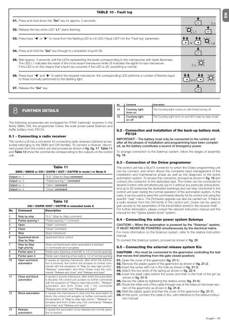
TABLE 10 - Fault logEN01. Press and hold down the “Set” key for approx. 3 seconds;02. Release the key when LED “L1” starts flashing;L1SETSET3 s03. Press keys “⊳” or “” to move from the flashing LED to L8 LED (“input LED”) for the “Fault log” parameter;orL804. Press and hold the “Set” key through to completion of point 06;SET05. Wait approx. 3 seconds until the LEDs representing the levels corresponding to the manoeuvres with faults illuminate.The LED L1 indicates the result of the most recent manoeuvre while L8 indicates the eighth-to-last manoeuvre.If the LED is on this means that a fault has occurred; if the LED is off, everything is normal;3 s06. Press keys “⊳” and “” to select the required manoeuvre: the corresponding LED performs a number of flashes equalto those normally performed by the flashing light;and07. Release the “Set” key.SET8FURTHER DETAILSThe following accessories are envisaged for <strong>HYKE</strong> (optional): receivers in thefamily SMXI, OXI, the programmer Oview, the solar power panel Solemyo andbuffer battery mod. PS124.8.1 - Connecting a radio receiverThe control unit has a connector for connecting radio receivers (optional accessories) belonging to the SMXI and OXI families. To connect a receiver, disconnectpower from the control unit and proceed as shown in fig. fig. 17. Table 11and Table 12 show the commands corresponding to the outputs on the controlunit.Table 11SMXI / SMXIS or OXI / OXIFM / OXIT / OXITFM in mode I or Mode IIOutput no. 1“S.S.” (Step by Step) commandOutput no. 2“Partial opening 1” commandOutput no. 3“Open” commandOutput no. 4“Close” commandTable 12OXI / OXIFM /OXIT / OXITFM in extended mode IINo. Command Description1 Step by step2 Partial opening 13 Open4 Close5 Stop6 Apartment blockStep by Step7 Step by Stephigh priority8 Partial open 29 Partial open 310 Open and blockautomation11 Close and blockautomation12 Block automation13 Releaseautomation“S.S.” (Step by Step) command“Partial opening 1” command“Open” command“Close” commandStops manoeuvreApartment block controlGives command even when automation is blockedor commands are in progressPartial open (Opening of leaf M2 to 1/2 of normal opening)Partial open (Opening of two leafs to 1/2 of normal opening)It causes an opening manoeuvre, after which the automationis blocked; the control unit accepts no further commandswith the exception of “Step by step high priority”,“Release” automation and (from Oview only) the commands“Release and close” and “Release and open”It causes a closure manoeuvre, after which the automationis blocked; the control unit accepts no further commandswith the exception of “Step by step high priority”, “Release”automation and (from Oview only ) the commands“Release and close” and “Release and open”It causes the manoeuvre to stop and the automation toblock; the control unit accepts no further commands withthe exception of “Step by step high priority”, “Release” au -to mation and (from Oview only ) the commands “Releaseand close” and “Release and open”.It causes the automation to be released and normal operationto resumeNo. Command Description14 Courtesy lighttimer on15 Courtesy lighton-offThe Courtesy light comes on with timed turning offThe Courtesy light turns on and off in step-by-step mode8.2 - Connection and installation of the back-up battery mod.PS124IMPORTANT! - The battery must only be connected to the control unitafter all the phases of installation and programming have been completed,as the battery constitutes a source of emergency power.To arrange connection to the Solemyo system, follow the stages of assemblyfig. 18.8.3 - Connection of the Oview programmerThe control unit has a BusT4 connector to which the Oview programming unitcan be connect, and which allows the complete rapid management of theinstallation and maintenance phase as well as the diagnosis of the entireautomation system. To access this connector, proceed as shown in fig. 19 andconnect the connector to the dedicated seat. The Oview can be connected toseveral Control units simultaneously (up to 5 without any particular precautions,and up to 60 observing the dedicated warnings) and can stay connected to thecontrol unit even during the normal operation of the automation system. In thiscase, it can be used to send the commands directly tot he control unit using thespecific "user" menu. The Firmware upgrade can also be carried out. If there isa radio receiver from the OXI family in the control unit, Oview can be used togain access to the parameters of the transmitters stored in the receiver itself.For further information, please consult the relevant instruction manual and themanual for the “Opera system book” system.8.4 - Connecting the solar power system SolemyoCAUTION! – When the automation is powered by the “Sole myo” system,IT MUST NEVER BE POWERED simultaneously by the electrical mains.For more information on the Solemyo system, refer to the relative instructionmanual.To connect the Solemyo system, proceed as shown in fig. 208.5 - Connecting the external release system KioCAUTION! – Kio must be connected to the gearmotor controlling the leafthat moves first (starting from the gate closed position).01. Open the cover of the gearmotor (fig. 21-1).02. Remove the plastic guard of the gearmotor as shown in fig. 21-2;03. Insert the screw with nut in the hole as shown in fig. 21-3;04. Attach the two ends of the spring as shown in fig. 22-4;05. Insert the steel cable before the screw and then in the hole of the pin asshown in fig. 21-5;06. Secure the cable by tightening the relative screw (fig. 21-5);07. Route the other end of the cable through one of the holes on the lower sectionof the gearmotor as shown in fig. 21-6;08. Refit the plastic guard and then the cover of the gearmotor (fig. 21-7);09. At this point, connect the cable to Kio, with reference to the relative instructionmanual.English – 11